WO2017119465A1 - 繊維強化樹脂成形体の製造方法 - Google Patents
繊維強化樹脂成形体の製造方法 Download PDFInfo
- Publication number
- WO2017119465A1 WO2017119465A1 PCT/JP2017/000198 JP2017000198W WO2017119465A1 WO 2017119465 A1 WO2017119465 A1 WO 2017119465A1 JP 2017000198 W JP2017000198 W JP 2017000198W WO 2017119465 A1 WO2017119465 A1 WO 2017119465A1
- Authority
- WO
- WIPO (PCT)
- Prior art keywords
- fiber
- molding material
- molding
- mold
- reinforced resin
- Prior art date
Links
Images


Classifications
-
- B—PERFORMING OPERATIONS; TRANSPORTING
- B29—WORKING OF PLASTICS; WORKING OF SUBSTANCES IN A PLASTIC STATE IN GENERAL
- B29C—SHAPING OR JOINING OF PLASTICS; SHAPING OF MATERIAL IN A PLASTIC STATE, NOT OTHERWISE PROVIDED FOR; AFTER-TREATMENT OF THE SHAPED PRODUCTS, e.g. REPAIRING
- B29C70/00—Shaping composites, i.e. plastics material comprising reinforcements, fillers or preformed parts, e.g. inserts
- B29C70/04—Shaping composites, i.e. plastics material comprising reinforcements, fillers or preformed parts, e.g. inserts comprising reinforcements only, e.g. self-reinforcing plastics
- B29C70/28—Shaping operations therefor
- B29C70/40—Shaping or impregnating by compression not applied
- B29C70/42—Shaping or impregnating by compression not applied for producing articles of definite length, i.e. discrete articles
- B29C70/46—Shaping or impregnating by compression not applied for producing articles of definite length, i.e. discrete articles using matched moulds, e.g. for deforming sheet moulding compounds [SMC] or prepregs
-
- B—PERFORMING OPERATIONS; TRANSPORTING
- B29—WORKING OF PLASTICS; WORKING OF SUBSTANCES IN A PLASTIC STATE IN GENERAL
- B29C—SHAPING OR JOINING OF PLASTICS; SHAPING OF MATERIAL IN A PLASTIC STATE, NOT OTHERWISE PROVIDED FOR; AFTER-TREATMENT OF THE SHAPED PRODUCTS, e.g. REPAIRING
- B29C43/00—Compression moulding, i.e. applying external pressure to flow the moulding material; Apparatus therefor
- B29C43/02—Compression moulding, i.e. applying external pressure to flow the moulding material; Apparatus therefor of articles of definite length, i.e. discrete articles
- B29C43/021—Compression moulding, i.e. applying external pressure to flow the moulding material; Apparatus therefor of articles of definite length, i.e. discrete articles characterised by the shape of the surface
-
- B—PERFORMING OPERATIONS; TRANSPORTING
- B29—WORKING OF PLASTICS; WORKING OF SUBSTANCES IN A PLASTIC STATE IN GENERAL
- B29C—SHAPING OR JOINING OF PLASTICS; SHAPING OF MATERIAL IN A PLASTIC STATE, NOT OTHERWISE PROVIDED FOR; AFTER-TREATMENT OF THE SHAPED PRODUCTS, e.g. REPAIRING
- B29C43/00—Compression moulding, i.e. applying external pressure to flow the moulding material; Apparatus therefor
- B29C43/32—Component parts, details or accessories; Auxiliary operations
- B29C43/36—Moulds for making articles of definite length, i.e. discrete articles
-
- B—PERFORMING OPERATIONS; TRANSPORTING
- B29—WORKING OF PLASTICS; WORKING OF SUBSTANCES IN A PLASTIC STATE IN GENERAL
- B29C—SHAPING OR JOINING OF PLASTICS; SHAPING OF MATERIAL IN A PLASTIC STATE, NOT OTHERWISE PROVIDED FOR; AFTER-TREATMENT OF THE SHAPED PRODUCTS, e.g. REPAIRING
- B29C70/00—Shaping composites, i.e. plastics material comprising reinforcements, fillers or preformed parts, e.g. inserts
- B29C70/04—Shaping composites, i.e. plastics material comprising reinforcements, fillers or preformed parts, e.g. inserts comprising reinforcements only, e.g. self-reinforcing plastics
- B29C70/28—Shaping operations therefor
- B29C70/54—Component parts, details or accessories; Auxiliary operations, e.g. feeding or storage of prepregs or SMC after impregnation or during ageing
- B29C70/541—Positioning reinforcements in a mould, e.g. using clamping means for the reinforcement
-
- B—PERFORMING OPERATIONS; TRANSPORTING
- B29—WORKING OF PLASTICS; WORKING OF SUBSTANCES IN A PLASTIC STATE IN GENERAL
- B29C—SHAPING OR JOINING OF PLASTICS; SHAPING OF MATERIAL IN A PLASTIC STATE, NOT OTHERWISE PROVIDED FOR; AFTER-TREATMENT OF THE SHAPED PRODUCTS, e.g. REPAIRING
- B29C70/00—Shaping composites, i.e. plastics material comprising reinforcements, fillers or preformed parts, e.g. inserts
- B29C70/04—Shaping composites, i.e. plastics material comprising reinforcements, fillers or preformed parts, e.g. inserts comprising reinforcements only, e.g. self-reinforcing plastics
- B29C70/28—Shaping operations therefor
- B29C70/54—Component parts, details or accessories; Auxiliary operations, e.g. feeding or storage of prepregs or SMC after impregnation or during ageing
- B29C70/543—Fixing the position or configuration of fibrous reinforcements before or during moulding
-
- B—PERFORMING OPERATIONS; TRANSPORTING
- B29—WORKING OF PLASTICS; WORKING OF SUBSTANCES IN A PLASTIC STATE IN GENERAL
- B29C—SHAPING OR JOINING OF PLASTICS; SHAPING OF MATERIAL IN A PLASTIC STATE, NOT OTHERWISE PROVIDED FOR; AFTER-TREATMENT OF THE SHAPED PRODUCTS, e.g. REPAIRING
- B29C70/00—Shaping composites, i.e. plastics material comprising reinforcements, fillers or preformed parts, e.g. inserts
- B29C70/04—Shaping composites, i.e. plastics material comprising reinforcements, fillers or preformed parts, e.g. inserts comprising reinforcements only, e.g. self-reinforcing plastics
- B29C70/28—Shaping operations therefor
- B29C70/54—Component parts, details or accessories; Auxiliary operations, e.g. feeding or storage of prepregs or SMC after impregnation or during ageing
- B29C70/545—Perforating, cutting or machining during or after moulding
-
- B—PERFORMING OPERATIONS; TRANSPORTING
- B29—WORKING OF PLASTICS; WORKING OF SUBSTANCES IN A PLASTIC STATE IN GENERAL
- B29C—SHAPING OR JOINING OF PLASTICS; SHAPING OF MATERIAL IN A PLASTIC STATE, NOT OTHERWISE PROVIDED FOR; AFTER-TREATMENT OF THE SHAPED PRODUCTS, e.g. REPAIRING
- B29C43/00—Compression moulding, i.e. applying external pressure to flow the moulding material; Apparatus therefor
- B29C43/02—Compression moulding, i.e. applying external pressure to flow the moulding material; Apparatus therefor of articles of definite length, i.e. discrete articles
- B29C43/021—Compression moulding, i.e. applying external pressure to flow the moulding material; Apparatus therefor of articles of definite length, i.e. discrete articles characterised by the shape of the surface
- B29C2043/022—Compression moulding, i.e. applying external pressure to flow the moulding material; Apparatus therefor of articles of definite length, i.e. discrete articles characterised by the shape of the surface having locally depressed lines, e.g. hinges
-
- B—PERFORMING OPERATIONS; TRANSPORTING
- B29—WORKING OF PLASTICS; WORKING OF SUBSTANCES IN A PLASTIC STATE IN GENERAL
- B29C—SHAPING OR JOINING OF PLASTICS; SHAPING OF MATERIAL IN A PLASTIC STATE, NOT OTHERWISE PROVIDED FOR; AFTER-TREATMENT OF THE SHAPED PRODUCTS, e.g. REPAIRING
- B29C43/00—Compression moulding, i.e. applying external pressure to flow the moulding material; Apparatus therefor
- B29C43/32—Component parts, details or accessories; Auxiliary operations
- B29C43/36—Moulds for making articles of definite length, i.e. discrete articles
- B29C2043/3602—Moulds for making articles of definite length, i.e. discrete articles with means for positioning, fastening or clamping the material to be formed or preforms inside the mould
-
- B—PERFORMING OPERATIONS; TRANSPORTING
- B29—WORKING OF PLASTICS; WORKING OF SUBSTANCES IN A PLASTIC STATE IN GENERAL
- B29K—INDEXING SCHEME ASSOCIATED WITH SUBCLASSES B29B, B29C OR B29D, RELATING TO MOULDING MATERIALS OR TO MATERIALS FOR MOULDS, REINFORCEMENTS, FILLERS OR PREFORMED PARTS, e.g. INSERTS
- B29K2101/00—Use of unspecified macromolecular compounds as moulding material
- B29K2101/12—Thermoplastic materials
-
- B—PERFORMING OPERATIONS; TRANSPORTING
- B29—WORKING OF PLASTICS; WORKING OF SUBSTANCES IN A PLASTIC STATE IN GENERAL
- B29K—INDEXING SCHEME ASSOCIATED WITH SUBCLASSES B29B, B29C OR B29D, RELATING TO MOULDING MATERIALS OR TO MATERIALS FOR MOULDS, REINFORCEMENTS, FILLERS OR PREFORMED PARTS, e.g. INSERTS
- B29K2105/00—Condition, form or state of moulded material or of the material to be shaped
- B29K2105/06—Condition, form or state of moulded material or of the material to be shaped containing reinforcements, fillers or inserts
-
- B—PERFORMING OPERATIONS; TRANSPORTING
- B29—WORKING OF PLASTICS; WORKING OF SUBSTANCES IN A PLASTIC STATE IN GENERAL
- B29K—INDEXING SCHEME ASSOCIATED WITH SUBCLASSES B29B, B29C OR B29D, RELATING TO MOULDING MATERIALS OR TO MATERIALS FOR MOULDS, REINFORCEMENTS, FILLERS OR PREFORMED PARTS, e.g. INSERTS
- B29K2307/00—Use of elements other than metals as reinforcement
- B29K2307/04—Carbon
-
- B—PERFORMING OPERATIONS; TRANSPORTING
- B29—WORKING OF PLASTICS; WORKING OF SUBSTANCES IN A PLASTIC STATE IN GENERAL
- B29L—INDEXING SCHEME ASSOCIATED WITH SUBCLASS B29C, RELATING TO PARTICULAR ARTICLES
- B29L2031/00—Other particular articles
- B29L2031/30—Vehicles, e.g. ships or aircraft, or body parts thereof
Definitions
- the present invention relates to a method for producing a fiber-reinforced resin molded article having ears from a molding material containing carbon fibers and a thermoplastic resin as a matrix.
- fiber reinforced resin material including a matrix resin and reinforcing fibers such as carbon fibers has been attracting attention in the mechanical field.
- These fiber reinforced resin materials are excellent in tensile elastic modulus, tensile strength, impact resistance and the like, and are being studied for use in structural members such as automobiles.
- fiber reinforced thermoplastic resin whose matrix resin is a thermoplastic resin, is superior in mass production, such as molding, compared to fiber reinforced resin material of thermosetting resin.
- There are various methods such as injection molding and compression molding for the molding of fiber reinforced thermoplastic resin materials, and it is easy to produce molded products according to the required characteristics by selecting the molding materials and methods appropriately. Reinforced thermoplastic resin moldings can be widely applied from large parts to small parts.
- press molding When manufacturing large parts using a fiber reinforced thermoplastic resin material as a molding material, press molding or the like can be suitably used.
- press molding the cavity space becomes a sealed space before the upper and lower molds (hereinafter, sometimes referred to as molds or simply molds) are closed, and the cavity internal pressure rises together with the mold clamping and is placed in the cavity.
- molds or simply molds A closed cavity method in which a molding material in a plastic state flows to transfer a molding die surface, and an open cavity method in which the cavity space is released even after clamping and the cavity surface pressure is applied are known.
- the closed cavity method when a molding material that is fluid in the plastic state is used, it is possible to fluidly fill the entire cavity space, and the product wall thickness is excellent even in uneven thickness parts and deep drawn parts. Since the internal pressure is increased, the surface transferability of the mold is improved.
- the open cavity method if a molding material that is fluid in the plastic state is used, the press molding force is consumed considerably by the molding material flowing out from the end of the mold, and a part of the cavity is part of the molding material. Therefore, it is preferable to use it for molding a molding material that does not flow even in a plastic state (sometimes referred to as a non-flowable molding material). .
- Patent Document 1 discloses a method in which an excess part is provided at the end portion of the product cavity, and the excess part is filled with molten resin and molded, and then the excess part is trimmed and finished in order to solve these problems. Presenting. In this method, it is possible to improve the appearance of the product part by collecting cold slugs etc.
- Patent Document 2 proposes that a product having a good appearance is obtained by molding the ear portion after trimming by the open cavity method to obtain a product portion. This method can be applied to press molding as in the present invention. However, because of the open cavity method, when a molding material with good fluidity is used, if the cavity internal pressure rises due to clamping, the opening of the molding die mating surface Molding material flows out of the mold, making molding difficult. Therefore, in the present invention, this is achieved by molding a molding material that does not flow even in a thermoplastic state without increasing the cavity internal pressure.
- Patent Document 3 a sheet material in which a discontinuous fiber reinforced thermoplastic resin layer is laminated on at least a part of one surface of a continuous fiber reinforced thermoplastic resin layer is press-molded to produce a fiber reinforced thermoplastic resin molded product.
- a frame-like weir portion that prevents the discontinuous fiber reinforced thermoplastic resin layer from flowing out of the cavity when the mold is closed is provided on the outer peripheral edge of the cavity.
- Patent Document 4 discloses a mold having a concave mold having an opening and a flange, and a convex mold having a convex corresponding to the concave and having a cavity between the concave mold. Is a method of press-molding a molding material composed of reinforcing fibers and a thermoplastic resin (hereinafter referred to as a press-molding material unless otherwise noted), and is reinforced on a mold that is a lower surface of the molding die.
- a press-molding material hereinafter referred to as a press-molding material unless otherwise noted
- a step of laminating and arranging molding materials (A) and (B) having at least the following two types of shapes comprising fibers and a thermoplastic resin, and a molding material laminated and arranged on a die that becomes the lower surface of the molding die There is disclosed a press molding method including a step of pressing (A) and (B) using a mold that is an upper surface of the mold.
- Molding material (B) a shape having a projected area at least equal to or larger than the projected area of the opening of the recess.
- FIG. 8 of Patent Document 4 shows a mechanism for sandwiching and fixing a molding material at the time of clamping.
- This mechanism is a mechanism that sandwiches and fixes the molding material before the upper mold contacts the molding material, and is a mechanism that slides a portion to be fixed together with mold clamping. This mechanism prevents the molding material from being pulled in when the mold is clamped, and prevents the upper molding material from shifting.
- the invention of this Patent Document 4 makes it easy to follow a complex shape of a mold and excellent workability that does not require a complicated process in press molding using a molding material composed of reinforcing fibers and a thermoplastic resin. It is said that it is a press molding method that has excellent moldability that can be achieved.
- the invention relates to two types of molding material (A) having a shape larger than the maximum area of the cavity and shape molding material (B) having a projection area at least larger than the projection area of the opening of the recess.
- Requires molding material It can be seen from the definitions that both the molding material (A) and the molding material (B) have a size corresponding to the main part of the target molded product. It may not be so cumbersome as long as the press molding is performed by partially laminating patch-shaped molding material pieces on the main molding material.
- two molding materials having a size corresponding to the main part of the target molded product and slightly different sizes are prepared and specified in a plastic state. The manufacturing method of a molded product that is placed in a mold under the above conditions and conditions and press-molded is considerably troublesome, and there is room for considerable improvement in terms of workability and mass productivity.
- An object of the present invention is to provide a method for producing a fiber-reinforced resin molded article excellent in appearance with high mass productivity.
- the present invention relates to a method for producing a fiber-reinforced resin molded body, in which a molding material containing reinforcing fibers and a thermoplastic resin as a matrix is clamped and press-molded with a molding die having an upper die and a lower die. Then, a molding material that is heated and in a plastic state is placed between the upper mold and the lower mold, and mold clamping is started, and a force in a substantially mold clamping direction is applied to a portion where the molding material is present, After starting to deform the molding material in the approximate clamping direction, a force in the approximate clamping direction is applied to a fixing portion that is at least a part of the approximately outer peripheral end of the molding material but is different from the certain portion.
- this invention relates to the manufacturing method of a fiber reinforced resin processed article including the process which cut
- a fiber reinforced resin molded article having excellent appearance can be produced with high mass productivity. Furthermore, in the production method of the present invention, the surface transfer from the mold to the molded body is excellent.
- FIG. 5 is a schematic view of a cross section of a cavity-shaped molding die in the vicinity of a substantially outer peripheral end portion where the outermost portion of the substantially central portion (product shape portion) of the cavity gradually decreases in thickness and leads to the pinching portion.
- 6A to 6D show the operation of the molding die and the molding material when the molding material heated and plasticized is clamped and press-molded in a molding die having an upper die and a lower die in Example 1 and the like.
- FIG. 6A is a schematic view of a state where the molding material is disposed between the upper mold and the lower mold.
- FIG. 6B shows a state in which mold clamping is started, a force in a substantially mold clamping direction is applied to a portion of the molding material, and the molding material starts to be deformed in a substantially mold clamping direction.
- FIG. 4 is a schematic view of a state in which the periphery (substantially central portion) of the molding material has started to be drawn into the space around the convex portion of the lower mold by the concave portion of the upper mold.
- FIG. 6C is a schematic view of a state in which a force in a substantially clamping direction is applied to a fixing portion at a substantially outer peripheral end portion of the molding material, and the fixing portion is pushed and fixed.
- FIG. 6D is a schematic view of a state where the mold clamping is completed.
- the present invention relates to a method for producing a fiber-reinforced resin molded body, in which a molding material containing reinforcing fibers and a thermoplastic resin as a matrix is clamped and press-molded with a molding die having an upper die and a lower die. And a molding material that is heated and in a plastic state (which may be simply referred to as “in the thermoplastic state” or “in the plastic state” for the present invention) is placed between the upper and lower molds.
- the mold clamping is started, and a force in a substantially mold clamping direction is applied to a portion of the molding material to start deformation of the molding material in the substantial mold clamping direction.
- At least a part of the fixing part that is different from the above-mentioned part is applied with a force in the direction of clamping, and the fixing part is pushed, preferably crushed and fixed, and then the clamping is completed.
- the ear portion of the fiber reinforced resin molded body is formed by press molding in which the above-mentioned fixing portion of the molding material is fixed by applying a force in a substantially clamping direction. Is done.
- a force is applied in the direction of substantial clamping, which means that the force is applied in the direction from the upper mold to the lower mold, the direction from the lower mold to the upper mold, or both directions. Also good.
- the approximate clamping direction is basically the clamping direction, but due to the shape of the molding die and the arrangement of the molding material, the force acting on the molding material from the molding die due to the clamping is slightly clamped.
- the direction may be a direction that deviates from the direction. If the numerical range is deliberately limited with respect to the approximate clamping direction, the clamping direction is preferably within a range of ⁇ 45 ° as viewed from a certain plane including the clamping direction, and the clamping direction is within a range of ⁇ 30 °. More preferably, it is more preferably in the range of the clamping direction ⁇ 15 °.
- placing the molding material between the upper mold and the lower mold means that the molding material is placed on the lower mold, and the upper mold having an appropriate holding mechanism is used to hold the molding material on the upper mold.
- the “certain part” of the molding material is often the substantially central part (product shape part) of the molding material, but may be the substantially outer peripheral end of the molding material, or may be one part or a plurality of parts. This “certain part” may be referred to as an initial deformation part.
- a force in the direction of substantially clamping to a fixing portion which is at least a part of the substantially outer peripheral end portion of the molding material but is different from the above-described certain portion, and press the substantially outer peripheral end portion.
- a force in the approximate mold clamping direction is applied to a portion of the molding material to deform the molding material in the thermoplastic state in the approximate mold clamping direction.
- a force in a substantially clamping direction is applied to the fixing portion of the molding material by a mechanism such as a pinch portion of a mold cavity as described later, and the molding material is pressed, preferably crushed.
- a press molding machine capable of clamping with a predetermined pressure by a mechanism such as a hydraulic type, an electric type, or a mechanical type can be used.
- the predetermined pressure preferably has a clamping force capable of applying a pressure of 5 MPa to 30 MPa, preferably 10 MPa to 20 MPa with respect to the projected area of the cavity.
- the cavity internal pressure is brought about by the clamping force, it is preferably adjusted as appropriate.
- mold clamping is started and a force in the approximate mold clamping direction is applied to the area where the molding material is located. Then, after starting to deform the molding material in the approximate clamping direction, apply a force in the approximate clamping direction to the fixing portion that is at least a part of the approximately outer peripheral end portion of the molding material, and press the approximately outer peripheral end portion. After fixing, it is important to complete the mold clamping.
- the fixing of the molding material fixing part is performed after the substantially central part of the molding material starts to be drawn into the space around the convex part of the lower mold by the concave part of the upper mold, It is preferable that it is performed before the mold clamping is completed. According to the present invention, it becomes possible to produce a fiber reinforced resin molded article having excellent appearance with high mass productivity, and surface transferability from a mold to a molded article in molding is excellent. Production of a fiber-reinforced resin molded body having a pattern or a complex pattern on the surface is also extremely easy.
- the heating temperature of the molding material is a temperature equal to or higher than the temperature at which the molding material becomes a plastic state. Specifically, when the thermoplastic resin as the matrix is an amorphous resin, the temperature is equal to or higher than the glass transition temperature. In the case, it is heated to a temperature higher than the melting point. At this time, what is important is to push the fixing portion at the substantially outer peripheral end of the molding material prior to the completion of the mold clamping, preferably crushing and fixing.
- a mechanism that uses a slide mechanism on the upper die and mechanically moves the slide block of the crushing portion to contact with the molding material before clamping is considered.
- the pinching constant Kp (MPa ⁇ cm 2 / kN) expressed by the following equation (p) can be used as an index as the pressure behavior at the pinching portion formed at the substantially outer peripheral end of the cavity.
- ⁇ Pinching part maximum pressure (MPa) ⁇ Pinching part area (cm 2 ) / 10) ⁇ / Clamping force (kN) Pinching constant Kp (MPa ⁇ cm 2 / kN) (p)
- the value of the pinching constant Kp is preferably less than 0.5, and more preferably 0.3 or less.
- the pinching constant Kp is less than 0.5, it is preferable that the mold clamping force is consumed to crush the pinching portion, and molding defects due to a decrease in the pressure in the cavity are less likely to occur.
- the pinching constant Kp (MPa ⁇ cm 2 / kN) is greater than 0.05, the effect of pressing a part of the substantially outer peripheral edge of the molding material at the pinching portion is reduced, and the plasticized molding material flows out from the pinching portion. This makes it difficult for problems to occur.
- the pinching constant Kp (MPa ⁇ cm 2 / kN) is preferably more than 0.05, more preferably more than 0.05 and less than 0.5, and even more preferably more than 0.05 and less than 0.3. preferable.
- an actual measurement value can be measured by a pressure sensor installed on the mold pinching part surface.
- adjusting the pinching portion pressure adjusting the clearance of the upper and lower molds of the pinching portion is exemplified. The preferred size of the pinching portion clearance greatly depends on the molding material used.
- the molding material having a small amount of reinforcing fibers and good fluidity requires a small clearance, and conversely, the molding material having a large amount of reinforcing fibers and entangled with the reinforcing fibers does not flow easily.
- a molding material of about 30 mm square is compressed and crushed under predetermined molding conditions, and estimated from the thickness of the obtained crushed piece The method of doing is illustrated. In this case, it is desirable to set the clearance at a size of 70% to 100%, preferably 80% to 90% of the thickness of the obtained crushed piece.
- the substantially central portion of the molded body with ears and the mold cavity that can be used in the manufacture thereof is not just the middle part, but the shape necessary for the use of the molded body with ears,
- a part having physical properties is referred to as a product shape part, but may be simply referred to as a central part.
- the substantially outer peripheral end portion referred to for the cavity and the molding material is a portion corresponding to the ear portion of the molded body obtained therefrom, and is a portion that is not substantially the central portion.
- the substantially outer peripheral end portion may be simply referred to as an outer peripheral end portion.
- the pinching portion means that when a mold starts to be clamped and a cavity is to be formed by the upper mold and the lower mold, that is, before the mold clamping is completed, at the substantially outer peripheral end of the cavity. It refers to a portion that is formed and has a smaller thickness than the substantially central portion of the cavity.
- the pinching part may be formed in the entire outer periphery of the substantially outer peripheral end part of the cavity, or may be formed in a part of the outer periphery.
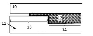
- the pinching portion is exemplified as the simplest aspect in which the pinching portion is formed to the outermost end of the substantially outer peripheral end portion of the cavity (see FIG. 3). It is preferable that the outermost portion of the substantially central part (product shape part) of the cavity is a cavity-shaped mold that leads to the pinching part with the cavity thickness gradually decreasing, and it is preferable because a molded article with ears that is more excellent in appearance can be obtained ( (See FIG. 4).
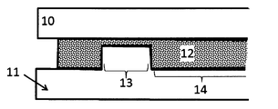
- the pinching portion is formed at a portion that is not the outermost end of the substantially outer peripheral end portion of the cavity, and as a result, the outermost cavity thickness of the substantially outer peripheral end portion of the cavity is larger than the thickness of the pinching portion. Even a cavity-shaped mold is preferable because it is easy to obtain a molded article with ears having a better appearance (see FIG. 5).
- the molded article with ears obtained by the production method of the present invention has, on the outer peripheral part, a part where the molding material is fixed at the pinching part of the mold cavity at the time of molding and an ear part corresponding to the part outside thereof. is there.
- the ear portion according to the present invention is not necessarily required in the usage of the molded body, but refers to an excess portion generated in the molded body due to the manufacturing method of the molded body as described above. Since this ear part includes a part formed by the flow of molding material, the state of orientation of reinforcing fibers has changed compared to the product shape part, and therefore the appearance and physical properties have changed compared to the product shape part. There are many.
- a fiber-reinforced resin molded article having a target product shape that does not have an ear part may be referred to as a fiber-reinforced resin processed product.
- the method for cutting the above-mentioned ears is not particularly limited, and a known method such as physical cutting such as circular saw, band saw, rutheter, end mill, or thermal cutting such as ultrasonic wave or laser should be used. Can do.
- the molded part with the ear part may be used as it is in the product for the reason that the part judged to be the ear part is unnecessary for a certain use and has a favorable effect in another use, it is included in the present invention. Is done. It is also possible to use the ear part of the molded article with the ear part for joining with other members, for example, mechanical fastening by bolts and nuts, vibration welding, or the like.
- the manufacturing method of the present invention can provide a molded article with an ear part that has a small ear part, which is difficult to obtain by the open cavity method press molding, by appropriately designing the fixing part.
- the effect of the present invention is particularly prominent when a molded article having a product shape having irregularities is obtained. This is because the pulling of the molding material at the time of the press molding is more likely to occur as the unevenness is larger, and defects such as unintended wrinkles are more likely to occur in the molded body.
- the molding material is hardly drawn.
- the molding material is likely to be drawn. This pull-in is caused by the difference between the projected area and the actual area of the cavity.
- the cavity has a planar part and a non-planar part in a cavity cross-sectional shape viewed from a direction substantially perpendicular to the clamping direction, and the surface of the planar part is continuous with the surface.
- the numerical range is deliberately limited in a direction substantially perpendicular to the approximate clamping direction, 90 ° ⁇ 45 ° with respect to the approximate clamping direction as viewed from a plane including a direction of 90 ° with respect to the approximate clamping direction.
- the range is preferably 90 ° ⁇ 30 ° with respect to the approximate clamping direction, and more preferably within the range of 90 ° ⁇ 15 ° with respect to the approximate clamping direction.
- a fiber reinforced resin material that is heated immediately before molding and is in a plastic state is placed in a mold that is adjusted to a temperature lower than the plasticization temperature of the fiber reinforced resin material, and the molded body is clamped.
- So-called cold press molding is preferable because of high productivity.
- a hot air heater, an infrared heater or the like is used as a method for heating the fiber reinforced resin material.
- Specific examples of cold press molding are as follows: After the fiber reinforced resin material is heated to a plasticizing temperature of a thermoplastic resin as a matrix + 30 ° C.
- the upper mold and the lower mold are configured in pairs, placed in a mold adjusted to a temperature equal to or lower than the softening temperature of the thermoplastic resin, clamped and pressurized, and the cooled and solidified molded body is opened. And take it out.
- the temperature at which the fiber reinforced resin material is heated to a plastic state is preferably a softening temperature + 15 ° C. or more and a decomposition temperature ⁇ 30 ° C.
- the heating temperature is within this range, it is preferable that the matrix resin is sufficiently melted and plasticized to be easily molded, and the thermoplastic resin is not decomposed so much.
- the pressurizing condition is preferably a press pressure of 0.1 MPa to 20 MPa, more preferably 0.2 MPa to 15 MPa, and further preferably 0.5 MPa to 10 MPa. Even more preferred.
- the press pressure is 0.1 MPa or more, the fiber-reinforced resin material can be sufficiently pressurized, so that it is difficult for spring back or the like to occur and the material strength is unlikely to decrease.
- the temperature in the mold during pressurization depends on the type of fiber reinforced resin material, but since the molten fiber reinforced resin material is cooled and solidified, a fiber reinforced resin molded product is formed.
- the temperature is preferably 20 ° C. or lower than the softening temperature of the thermoplastic resin which is the matrix of the material.
- the softening temperature of the resin is the crystal melting temperature, that is, the so-called melting point, for the crystalline thermoplastic resin, and the glass transition temperature for the amorphous thermoplastic resin.
- the inventors consider the mechanism of manifestation of the effect of the production method of the present invention as follows:
- the above-described closed cavity is provided by providing a portion where the applied pressure changes locally during press molding.
- the advantage of this method is that it is possible to form an unevenly-walled molded product by increasing the cavity internal pressure and flow, and molding with excellent mold transferability. It has become possible to improve changes in appearance and physical properties at the end of the product.
- the press molding it is preferable to place a molding material or a plate-like material on the upper surface of the lower mold, and then close and pressurize the upper mold to fill and mold the molding material over the entire cavity.
- the molding material disposed on the upper surface of the lower mold is pressed by the convex portion of the upper mold at the same time as the mold clamping, and the phenomenon occurs because the concave portion of the lower mold is drawn.
- this pulling phenomenon occurs in an unstable manner in the molding process. Therefore, when the amount of the molding material is partially pulled in, the portion becomes a defective portion of the molding body that is not filled with the molding material, and is pulled back.
- the molding material protrudes to the outer peripheral portion of the cavity and is sandwiched between the shear edge portions constituting the closed cavity, resulting in defective molding.
- the molding material is fixed at the cavity outer peripheral portion, thereby eliminating unfilled molding defects and occurring at the end of the product. It became possible to prevent the appearance and physical properties from being disturbed.
- thermoplastic resin As the molding material containing the reinforcing fiber used in the present invention and the thermoplastic resin as the matrix (sometimes referred to as a fiber reinforced resin material in the present invention), known materials can be preferably used.
- the abundance of the thermoplastic resin as a matrix in the fiber reinforced resin material can be appropriately determined according to the type of the thermoplastic resin, the type of the reinforced fiber, and the like, and is not particularly limited.
- the thermoplastic resin is preferably in the range of 3 to 1000 parts by weight, more preferably 30 to 200 parts by weight, still more preferably 30 to 150 parts by weight with respect to 100 parts by weight of the reinforcing fibers. .
- the amount of the thermoplastic resin as a matrix is 3 parts by weight or more with respect to 100 parts by weight of the reinforcing fibers, the resin-impregnation in the fiber-reinforced resin material is sufficient, and dry reinforcing fibers are reduced.
- the amount of the thermoplastic resin as the matrix is 1000 parts by weight or less, the amount of the reinforcing fibers is sufficient and is often suitable as a structural material.
- the term weight is sometimes used for convenience, but it is actually mass.
- the orientation state of the reinforcing fiber in the fiber reinforced resin material for example, the unidirectional orientation in which the major axis direction of the reinforcing fiber is oriented in one direction or the major axis direction is randomly oriented in the in-plane direction of the fiber reinforced resin material.
- Two-dimensional random orientation can be mentioned.
- the orientation state of the reinforcing fiber in the fiber reinforced resin material used in the present invention may be either the above-mentioned unidirectional orientation or two-dimensional random orientation. It may be an irregular orientation intermediate between the unidirectional orientation and the two-dimensional random orientation (orientation state in which the major axis direction of the reinforcing fiber is not perfectly oriented in one direction and is not completely random).
- the long axis direction of the reinforcing fiber may be oriented so as to have an angle with respect to the in-plane direction of the fiber reinforced resin material, and the reinforcing fiber is oriented so as to be entangled in cotton.
- the reinforcing fibers may be oriented such as bi-directional woven fabrics such as plain weave and twill weave, multi-axial woven fabrics, non-woven fabrics, mats, knits, braids, paper made of reinforced fibers, and the like.
- the plane orientation degree ⁇ 100 ⁇ (1- (number of reinforcing fibers having a plane orientation angle ⁇ of 10 ° or more) / (total number of reinforcing fibers))) is 90% or more.
- a certain state may be a preferable two-dimensional random orientation.
- the thickness direction of the molded body or a direction different from the thickness direction of the molded body is defined as the Z direction, and observation and measurement regarding reinforcing fibers according to the above publication
- the plane orientation degree ⁇ may be calculated.
- the reinforcing fiber mat in the present invention refers to a mat formed by accumulation or entanglement of reinforcing fibers.
- the reinforcing fiber mat include a two-dimensional random reinforcing fiber mat in which the long axis direction of the reinforcing fiber is randomly oriented in the in-plane direction of the fiber reinforced resin material, and the long axis of the reinforcing fiber by entwining the reinforcing fibers in a cotton shape.
- a three-dimensional random reinforcing fiber mat whose direction is randomly oriented in each of the XYZ directions is exemplified.
- the isotropic substrate refers to a material in which a reinforcing fiber mat contains a thermoplastic resin.
- examples of the aspect in which the reinforcing fiber mat includes the thermoplastic resin include, for example, an aspect in which the reinforcing fiber mat includes a powdery, fibrous, or massive thermoplastic resin, or the reinforcing fiber mat.
- stacked can be mentioned.
- An isotropic substrate in which the reinforcing fiber mat is a two-dimensional random reinforcing fiber mat may be particularly referred to as an in-plane isotropic substrate.
- reinforcing fibers having different orientation states may be contained in one fiber reinforced resin material.
- the reinforcing fibers having different orientation states are included in the fiber reinforced resin material, for example, (i) an aspect in which reinforcing fibers having different orientation states are arranged in the in-plane direction of the fiber reinforced resin material, (ii) fibers
- the aspect by which the reinforced fiber from which an orientation state differs in the thickness direction of a reinforced resin material can be mentioned.
- a fiber reinforced resin material has a laminated structure which consists of a several layer, the aspect from which the orientation state of the reinforced fiber contained in each layer (iii) differs can be mentioned.
- An embodiment in which the above embodiments (i) to (iii) are combined can also be exemplified.
- the orientation of reinforcing fibers in the fiber reinforced resin material is, for example, a tensile test based on an arbitrary direction of the fiber reinforced resin material and a direction orthogonal thereto, and the tensile elastic modulus is measured and then measured This can be confirmed by measuring the ratio (E ⁇ ) obtained by dividing the larger value of the elastic modulus by the smaller value. It can be evaluated that the closer the modulus ratio is to 1, the more reinforced fibers are isotropically oriented. It is considered to be in-plane isotropic when the ratio of the modulus of elasticity in the two orthogonal directions divided by the smaller one does not exceed 2, and in-plane etc.
- Basis weight of the reinforcing fibers in the fiber-reinforced resin material is not particularly limited, the lower limit value is set to 25g / m 2 ⁇ 10000g / m 2.
- the basis weight of the reinforced fibers in the fiber reinforced resin material can be obtained. It can be regarded as the basis weight of reinforcing fibers in the body.
- the thickness of the fiber reinforced resin material used in the present invention is not particularly limited, but is usually preferably in the range of 0.01 mm to 100 mm, preferably in the range of 0.01 mm to 5 mm, and in the range of 1 to 5 mm. The inside is more preferable.
- the above thickness does not indicate the thickness of each layer, but indicates the total thickness of the fiber reinforced resin obtained by summing the thickness of each layer. To do.
- the fiber reinforced resin material used in the present invention may have a single layer structure composed of a single layer, or may have a laminated structure in which a plurality of layers are laminated.
- the aspect in which the fiber reinforced resin material has the above laminated structure may be an aspect in which a plurality of layers having the same composition are laminated, or an aspect in which a plurality of layers having different compositions are laminated. Also good.
- the fiber reinforced resin material has the above-described laminated structure
- layers having different orientation states of reinforcing fibers may be laminated.
- a layer in which reinforcing fibers are unidirectionally oriented and a layer in which two-dimensional random orientation is oriented may be laminated.
- a sandwich structure including an arbitrary core layer and a skin layer laminated on the front and back surfaces of the core layer may be used.
- various fibrous or non-fibrous fillers of organic fibers or inorganic fibers, flame retardants, UV-resistant agents, stabilizers, mold release, and the like within the range not impairing the object of the present invention.
- Additives such as agents, pigments, softeners, plasticizers, surfactants and the like may be included.
- the volume ratio of the reinforcing fiber contained in the molding material (fiber reinforced resin material) used in the production method of the present invention and the molded article with ears obtained by the production method of the present invention there is no particular limitation on the volume ratio of the reinforcing fiber contained in the molding material (fiber reinforced resin material) used in the production method of the present invention and the molded article with ears obtained by the production method of the present invention.
- the reinforcing fiber and the thermoplastic resin as the matrix preferably have a reinforcing fiber volume fraction (Vf) defined by the following formula (u) of 5% to 80%. Is more preferably 20% to 60%.
- Vf 100 ⁇ reinforcing fiber volume / (reinforcing fiber volume + thermoplastic resin volume) Formula (u)
- the average value of Vf is preferably in the above range, and more preferably, both the minimum value and the maximum value of Vf are in the above range.
- Vf of the molding material can be regarded as the Vf of the molded body with ears.
- the molding material (fiber reinforced resin material) used in the present invention preferably has a tensile elongation at break ⁇ v of 105% to 400%, more preferably 105% to 260%, and more preferably 110% to 230%. And even more preferable.
- a molding material having a tensile elongation at break ⁇ v of 105% or more is preferable because it is difficult to tear even if it is bent when placed in a mold.
- a molding material having a tensile elongation at break ⁇ v of 400% or less is preferable because it hardly hangs down by its own weight when the plastic material is transported by being gripped by a robot arm.
- the tensile elongation at break ⁇ v of the molding material is the elongation of the molding material when stretched at a tensile speed of 20 mm / sec at a temperature equal to or higher than the softening temperature of the thermoplastic resin as the matrix of the molding material. It is represented by the formula (e).
- ⁇ v (%) 100 ⁇ length after stretching of molding material / length before stretching of molding material (e) More specifically, the molding material was heated to a temperature above the softening temperature of the thermoplastic resin as the matrix, the molding material over the mold for press molding of the tensile elongation at break epsilon v for measurement After placing and closing the mold at a mold clamping speed of 20 mm / sec until the molding material is broken, the molding material is taken out and the length of the molding material stretched is measured. Calculated by dividing.
- Carbon fiber is preferable as the reinforcing fiber contained in the fiber-reinforced resin molded article or fiber-reinforced resin material having the ears of the present invention, but depending on the type of matrix resin, the use of the fiber-reinforced resin material, etc.
- Any inorganic fiber or organic fiber other than the above can be used.
- inorganic fibers other than the carbon fibers include activated carbon fibers, graphite fibers, glass fibers, tungsten carbide fibers, silicon carbide fibers (silicon carbide fibers), ceramic fibers, alumina fibers, natural fibers, mineral fibers such as basalt, boron, and the like. Examples thereof include fibers, boron nitride fibers, boron carbide fibers, and metal fibers.
- Examples of the metal fiber include aluminum fiber, copper fiber, brass fiber, stainless steel fiber, and steel fiber.
- As said glass fiber what consists of E glass, C glass, S glass, D glass, T glass, quartz glass fiber, borosilicate glass fiber, etc. can be mentioned.
- Examples of the organic fibers include fibers made of resin materials such as aramid, PBO (polyparaphenylene benzoxazole), polyphenylene sulfide, polyester, acrylic, polyamide, polyolefin, polyvinyl alcohol, and polyarylate.
- the reinforcing fiber contained in the molded article with ears and the fiber reinforced resin material according to the present invention is one or more reinforcing fibers selected from the group consisting of carbon fiber, glass fiber, aramid fiber, boron fiber, basalt fiber, It is more preferable that it is in the weight average fiber length range described later.
- two or more kinds of reinforcing fibers may be used in combination.
- a plurality of types of inorganic fibers may be used in combination
- a plurality of types of organic fibers may be used in combination
- inorganic fibers and organic fibers may be used in combination.
- Examples of the mode in which a plurality of types of inorganic fibers are used in combination include a mode in which carbon fibers and metal fibers are used in combination, and a mode in which carbon fibers and glass fibers are used in combination.
- examples of the mode in which a plurality of types of organic fibers are used in combination include a mode in which aramid fibers and fibers made of other organic materials are used in combination.
- the aspect which uses together a carbon fiber and an aramid fiber can be mentioned, for example.
- carbon fibers are preferred as the reinforcing fibers. This is because carbon fiber can provide a fiber-reinforced resin material that is lightweight but has excellent strength.
- the carbon fiber generally, polyacrylonitrile (PAN) -based carbon fiber, petroleum pitch-based carbon fiber, coal pitch-based carbon fiber, rayon-based carbon fiber, cellulose-based carbon fiber, lignin-based carbon fiber, phenol-based carbon fiber, Vapor growth carbon fibers and the like are known, but any of these carbon fibers can be suitably used in the present invention.
- PAN polyacrylonitrile
- the tensile elastic modulus is preferably within a range of 100 GPa to 600 GPa, more preferably within a range of 200 GPa to 500 GPa, and within a range of 230 GPa to 450 GPa. Is more preferable. Further, the tensile strength is preferably in the range of 2000 MPa to 10,000 MPa, and more preferably in the range of 3000 MPa to 8000 MPa.
- the reinforcing fiber used in the present invention may have a sizing agent attached to the surface in order to improve the adhesion with the matrix resin.
- the type of the sizing agent can be appropriately selected according to the types of the reinforcing fiber and the matrix resin, and is not particularly limited.
- the adhesion strength between the reinforcing fiber and the matrix resin is preferably 5 MPa or more in the strand tensile shear test.
- this strength can be obtained by a method of changing the surface oxygen concentration ratio (O / C) or by applying a sizing agent to the carbon fiber so that the carbon fiber and the matrix It can be improved by a method of increasing the adhesion strength with the resin.
- the reinforcing fibers when at least a part of the reinforcing fibers has a monofilament shape, the effect becomes extremely remarkable.
- a part of the reinforcing fibers in order to increase the fluidity of the fiber reinforced resin material, it is preferable that a part of the reinforcing fibers form a bundle of single fibers.
- the reinforcing fiber may be in the form of a single fiber or a single fiber bundle, but when both are provided, the effect of the present invention can be further obtained.
- the single fiber bundle means that two or more reinforcing single fibers are close to each other by a sizing agent, electrostatic force, or the like and exist in a bundle shape.
- the number of reinforcing single fibers forming the single fiber bundle is preferably 280 or more, and more preferably 600 or more.
- the number of single fibers constituting each single-fiber bundle may be substantially uniform or different in each single-fiber bundle.
- the weight average fiber length of the reinforcing fibers contained in the molded article with ears and the fiber-reinforced resin material of the present invention is preferably 0.1 mm to 500 mm from the viewpoint of both strength and productivity.
- the weight average fiber length is more preferably 1 mm to 100 mm, still more preferably 5 mm to 100 mm, and still more preferably 10 mm to 100 mm.
- As the reinforcing fiber used in the present invention not only a discontinuous fiber having a weight average fiber length of 100 mm or less, which is excellent in in-plane isotropic strength and dimensions as described above, but a continuous fiber may be used depending on the purpose.
- reinforcing fibers having different fiber lengths may be used in combination.
- the reinforcing fiber used in the present invention may have a single peak in average fiber length, or may have a plurality of peaks.
- the average fiber length of the reinforced fibers is measured, for example, by measuring the fiber length of 100 fibers randomly extracted from the fiber reinforced resin material to the 1 mm unit using a caliper or the like, and the following formulas (m) and (f) Can be determined based on
- the method for extracting reinforcing fibers from the fiber reinforced resin material can be performed, for example, by subjecting the fiber reinforced resin material to a heat treatment of about 500 ° C. ⁇ 1 hour and removing the resin in a furnace.
- Number average fiber length Ln ⁇ Li / j (m) (Where Li is the fiber length of the reinforcing fiber and j is the number of reinforcing fibers)
- Weight average fiber length Lw ( ⁇ Li 2 ) / ( ⁇ Li) (f) (Where Li is the fiber length of the reinforcing fiber)
- the number average fiber length can be regarded as the weight average fiber length.
- the number average fiber length or the weight average fiber length may be adopted, but it is often the weight average fiber length that can more accurately reflect the physical properties of the fiber reinforced resin material.
- the single fiber diameter of the reinforcing fiber used in the present invention may be appropriately determined according to the type of the reinforcing fiber, and is not particularly limited.
- the average single fiber diameter is usually preferably in the range of 3 ⁇ m to 50 ⁇ m, more preferably in the range of 4 ⁇ m to 12 ⁇ m, and in the range of 5 ⁇ m to 8 ⁇ m. More preferably.
- the average single fiber diameter is preferably in the range of 3 to 30 ⁇ m.
- the average single fiber diameter refers to the diameter of the single fiber of the reinforcing fiber as the name suggests, but when the reinforcing fiber is a bundle of single fibers, the average single fiber diameter is the average fiber diameter. May be abbreviated.
- the average single fiber diameter of the reinforcing fiber can be measured, for example, by the method described in JIS R7607 (2000).
- the reinforcing fibers used in the present invention include a single fiber bundle, that is, two or more reinforcing single fibers that are close together and bundled by a sizing agent or electrostatic force.
- the reinforcing fiber in the form of a single fiber bundle may be referred to as a reinforcing fiber bundle for convenience.
- One reinforcing fiber bundle functions as one filler in the fiber reinforced resin molded body and its molding material.
- a bundle of multiple single fibers is obtained by randomly collecting individual reinforcing fibers with tweezers from a reinforcing fiber sample obtained by removing the matrix thermoplastic resin from a fiber reinforced resin molding or molding material.
- a typical example of the reinforcing fiber bundle is one in which a plurality of single fibers are oriented in the same direction and their longitudinal side surfaces are in contact with each other to form a bundle shape, but is not limited to this form.
- a plurality of single fibers may be bundled in various directions, and a plurality of single fibers are close to each other at a part of the longitudinal side surface, but at other parts, the single fibers are separated from each other. It may be a bundle shape.
- the reinforcing fibers used in the present invention are single fiber bundles, the number of single fibers constituting each single fiber bundle is not particularly limited, but is usually in the range of 2 to 100,000.
- carbon fibers are in the form of a single fiber bundle in which thousands to tens of thousands of single fibers are gathered.
- the reinforcing fibers if they are used in the form of a single fiber bundle, the entangled portion of the single fiber bundle may be locally thick and it may be difficult to obtain a thin fiber reinforced resin material. For this reason, when using a reinforcing fiber in the form of a single fiber bundle, the single fiber bundle is usually used after being widened or opened.
- the reinforcing fiber in the present invention is represented by the following formula (1).
- Number of critical single fibers 600 / D (1) (Where D is the average single fiber diameter ( ⁇ m) of the reinforced single fibers)
- the reinforcing fiber (A) composed of a single fiber of a number equal to or greater than the critical single fiber defined in (1) is preferably an amount such that the ratio to the total amount of reinforcing fibers is 20 vol% or more, and is an amount that is 30 vol% or more. The amount is more preferably 40 vol% or more, and particularly preferably 50 vol% or more.
- a reinforcing fiber other than the reinforcing fiber (A) there is a single fiber bundle composed of a single fiber in a single fiber state or a number of single fibers less than the critical single fiber, and may be referred to as a reinforcing fiber (B) hereinafter. May be.
- the thickness of the reinforcing fiber (A) comprised by more than the specific single fiber number is reduced, and the number of bundles of the reinforcing fiber (A) per reinforcing fiber unit weight (g). Since the thickness unevenness of the fiber reinforced resin material can be reduced by setting it to a specific range, a fiber reinforced resin molded article having excellent mechanical properties can be obtained by molding a fiber reinforced resin material containing such reinforced fibers. Is possible.
- the ratio of the amount of reinforcing fiber (A) to the total amount of carbon fiber is 20 vol% or more, it is easy to obtain a good molded article having a high reinforcing fiber volume content when the fiber-reinforced resin material of the present invention is molded. It is preferable. On the other hand, it is preferable that the upper limit of the ratio of the amount of the reinforcing fiber (A) is 99 vol%. If the ratio of the amount of reinforcing fiber (A) to the total amount of fibers is 99 vol% or less, the fiber gap is not increased, and a composite material having excellent mechanical strength can be obtained.
- the ratio of the amount of reinforcing fiber (A) to the total amount of reinforcing fibers is more preferably 50 vol% or more and less than 99 vol%, and still more preferably 60 vol% or more and 90 vol% or less. That is, the upper limit of the ratio of the amount of reinforcing fiber (A) to the total amount of reinforcing fibers is more preferably 95 vol% or less, and still more preferably 90 vol% or less.
- the reinforcing fiber (A) is a bundle of reinforcing single fibers, it may be referred to as a reinforcing fiber bundle (A) for convenience.
- the average number of single fibers of the reinforcing fiber (A) may be abbreviated as the average number of fibers.
- thermoplastic resin In the molded article with ears and the fiber reinforced resin material according to the present invention, a thermoplastic resin is included as a matrix resin.
- a thermoplastic resin As the matrix resin, a thermosetting resin may be used in combination as long as the main component is a thermoplastic resin.
- the thermoplastic resin is not particularly limited, and a resin having a desired softening temperature can be appropriately selected and used depending on the use of the molded article with ears or the processed product thereof.
- the thermoplastic resin those having a softening temperature in the range of 180 ° C. to 350 ° C. are preferably used, but are not limited thereto.
- the softening temperature of the thermoplastic resin is the crystal melting temperature, so-called melting point, for the crystalline thermoplastic resin, and the glass transition temperature for the amorphous thermoplastic resin.
- thermoplastic resin examples include polyolefin resin, polystyrene resin, thermoplastic polyamide resin, polyester resin, polyacetal resin (polyoxymethylene resin), polycarbonate resin, (meth) acrylic resin, polyarylate resin, polyphenylene ether resin, polyimide resin, One or more kinds selected from the group consisting of polyether nitrile resin, phenoxy resin, polyphenylene sulfide resin, polysulfone resin, polyketone resin, polyether ketone resin, thermoplastic urethane resin, fluorine resin, thermoplastic polybenzimidazole resin, etc. Can be mentioned.
- polystyrene resin examples include one or more selected from the group consisting of polyethylene resin, polypropylene resin, polybutadiene resin, polymethylpentene resin, vinyl chloride resin, vinylidene chloride resin, vinyl acetate resin, polyvinyl alcohol resin, and the like.
- polystyrene resin examples include one or more selected from the group consisting of polystyrene resin, acrylonitrile-styrene resin (AS resin), acrylonitrile-butadiene-styrene resin (ABS resin), and the like.
- polyamide resin examples include polyamide 6 resin (nylon 6), polyamide 11 resin (nylon 11), polyamide 12 resin (nylon 12), polyamide 46 resin (nylon 46), polyamide 66 resin (nylon 66), and polyamide 610.
- polyamide 610 polyamide 6 resin
- polyamide 11 resin polyamide 11
- polyamide 12 resin polyamide 12
- polyamide 46 resin polyamide 46
- polyamide 66 resin polyamide 610
- polyamide 610 polyamide 610.
- polyester resin examples include polyethylene terephthalate resin, polyethylene naphthalate resin, boribylene terephthalate resin, polytrimethylene terephthalate resin, and liquid crystal polyester.
- Examples of the (meth) acrylic resin include polymethyl methacrylate.
- Examples of the modified polyphenylene ether resin include modified polyphenylene ether.
- Examples of the thermoplastic polyimide resin include thermoplastic polyimide, polyamideimide resin, polyetherimide resin, and the like.
- Examples of the polysulfone resin include one or more types selected from the group consisting of a modified polysulfone resin, a polyethersulfone resin, and the like.
- Examples of the polyether ketone resin include one or more selected from the group consisting of a polyether ketone resin, a polyether ether ketone resin, and a polyether ketone ketone resin.
- fluororesin, polytetrafluoroethylene etc. can be mentioned, for example.
- thermoplastic resin used in the present invention may be only one type or two or more types.
- modes in which two or more types of thermoplastic resins are used in combination include modes in which thermoplastic resins having different softening temperatures are used in combination and modes in which thermoplastic resins having different average molecular weights are used in combination. But this is not the case.
- the fiber reinforced resin material used in the present invention can be produced using a known method.
- a thermoplastic resin for example: 1. a step of cutting the reinforcing fiber; 2. opening the cut reinforcing fiber; It is possible to manufacture the fiber-reinforced resin material by mixing the opened reinforcing fiber and the fibrous or particulate matrix resin to obtain an isotropic base material, and then heating and compressing it to promote impregnation with the thermoplastic resin. Yes, but not necessarily.
- An isotropic substrate also called a two-dimensional random orientation mat
- a method for producing the same are described in detail in the specification of WO2012 / 105080 pamphlet and JP2013-49298A.
- a strand composed of a plurality of reinforcing fibers is continuously slit along the reinforcing fiber length direction as necessary to form a plurality of narrow strands having a width of 0.05 mm to 5 mm, and then an average fiber length of 3 mm to 100 mm.
- a mat is obtained by continuously cutting and depositing in layers on a breathable conveyor net etc. in a state where gas is blown to the cut reinforcing fibers to open them into reinforcing fibers having a smaller number of single fibers. be able to.
- thermoplastic resin in the form of granules or short fibers is deposited on the breathable conveyor net together with the reinforcing fibers, or the molten thermoplastic resin is supplied to the mat-like reinforcing fiber layer as a film and penetrated. It can also be produced by a method of producing an isotropic substrate including a thermoplastic resin.
- the size of the reinforcing fibers to be subjected to the cutting step in the above-described preferred method for producing an isotropic substrate for example, the width and width of the reinforcing fibers as a single fiber bundle It can be controlled by adjusting the number of single fibers per unit. Specifically, a method of expanding the width of the reinforcing fiber by expanding the width and using it for the cutting step, or a method of providing a slit step before the cutting step can be mentioned. Further, the reinforcing fiber may be slit simultaneously with the cutting.
- the reinforcing fibers are not oriented in a specific direction and are dispersed in a random direction in the plane. That is, such a fiber reinforced resin material is an in-plane isotropic material.
- the in-plane isotropy of the fiber reinforced resin material can be quantitatively evaluated.
- the external appearance of the flange part (it may be abbreviated as an end part in this example) and the vertical surface of the fiber reinforced resin molded article was visually observed and evaluated based on the following criteria.
- C (slightly good): The transfer on the mold surface is partially insufficient, and the surface has a mottled pattern, and the part where the surface gloss is lost and the part where the gloss is glossy can be clearly recognized.
- Full shot stability is a measure of whether a good molded article can be obtained even if press molding is continuously performed, that is, a molded article can be stably produced. As an evaluation of full shot stability, 20 shots were continuously formed, and when 20 full shot compacts were obtained, “good” was indicated when unfilled compacts were included.
- a hemispherical recess having a radius of 300 ⁇ m is provided on the surface of the mold, corresponding to the flange portion at the end of the target molded body, and the height of the hemisphere of the obtained molded body is determined. It was measured and evaluated by how close the height was to 300 ⁇ m.
- FIGS. 5 The position of the cavity pressure measured by the pressure sensor is shown in the schematic views of the molded body in FIGS. More precisely, a pressure sensor was installed at the position of the mold cavity surface corresponding to the position, and the cavity internal pressure was measured. Since this pressure sensor measures the pressure applied to the mold cavity surface, it becomes difficult to accurately measure the pressure applied to the molding material as the molding material in the cavity cools and solidifies. Therefore, in the embodiment of the present invention, the pressure for 3 seconds from the start of pressurization was measured, and the highest pressure was recorded during that time to obtain the pressure value.
- the thickness value of the obtained molded body is a value obtained by measuring the thickness at the position shown in the schematic view of the molded body in FIGS. 1 and 2 with a micrometer.
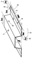
- Mold and mold shape As shown in FIG. 1 and FIG. 2, a mold composed of an upper mold and a lower mold is formed in which a cavity corresponding to a molded body having a hat-shaped cross section of 30 mm in height and 10 mm in thickness and 2.5 mm in thickness is formed. It was used for press molding.
- the width of the portion corresponding to the flange portion of the molded body is 40 mm, of which the portion having a width of 20 mm is a region having a thickness of 2.5 mm that is interpreted as a part of the substantially central portion of the cavity.
- the remaining width of 20 mm is a region including the pinching part of the cavity.
- the portion where the pinching portion is formed is a block having a nested structure, and the thickness and width of the pinching portion can be adjusted by exchanging the block.
- the longitudinal direction of the molded body obtained by molding using the mold is defined as the Y-axis direction of the XYZ coordinate system, and the height is defined as the Z-axis direction.
- the size of the molded body in the X-axis direction in this case is the width.
- a mold having a cavity shape corresponding to a 400 mm ⁇ 400 mm flat plate-shaped molded body (hereinafter sometimes referred to as a flat plate-shaped mold) was used.
- molding machine In this application, a hydraulic 5000 kN press machine manufactured by Kawasaki Oil Works Co., Ltd. was used. Unless otherwise specified, the molding conditions are the same. Specifically, a molding die, which will be described later, is attached, the pressing pressure is 15 MPa, the molding die temperature is 150 ° C., and the molding material heating temperature is 290 ° C. Molding was performed.
- a PAN-based carbon fiber “TENAX” registered trademark
- STS40-24KS average single fiber diameter: 7 ⁇ m, number of single fibers: 24,000
- An in-plane isotropic base material in which the fibers are two-dimensionally randomly oriented and has a carbon fiber basis weight of 1800 g / m 2 was prepared.
- the obtained in-plane isotropic base material was put into a flat plate mold set at 250 ° C., pressurized at 2 MPa for 10 minutes, the mold temperature was lowered to 100 ° C., and the carbon fibers were two-dimensionally randomly oriented.
- the molding material has a reinforcing fiber volume fraction (Vf) of 35%, the weight average fiber length of the reinforcing fibers contained is 20 mm, the number of critical single fibers is 86, and the total number of reinforcing fibers is not less than the number of critical single fibers.
- the ratio of the amount of the reinforcing fiber (A) composed of the carbon single fibers of the number was 77 vol%.
- bundles composed of carbon single fibers having a number less than the number of critical single fibers and single carbon fibers were also present.
- This molding material has a tensile elongation at break ⁇ v determined by the above formula (e) in the range of 105% to 400%.
- Example 1 Using the 2.6 mm thick molding material obtained in Production Example 1 cut into a 700 mm ⁇ 190 mm rectangular mold, press molding (20 shot continuous molding) was performed according to the following procedure.
- a mold having a cavity having a shape corresponding to a hat-shaped molded body having a height of 30 mm (FIG. 1) was used as the mold.
- the block of the pinching portion of this mold was set so that the gap (pinching portion) thickness was 1.5 mm and the width of the pinching portion was 10 mm from the end of the substantially central portion of the cavity.
- Clamping of the mold was started by placing the heated molding material in a plastic state on the lower mold of the mold so that both ends in the width direction are sandwiched between the pinching sections of the mold cavity. .
- the periphery of the central part of the molding material (substantially central part) is drawn into the space around the convex part of the lower mold by the concave part of the upper mold, and then both ends of the molding material are pushed by the pinching part of the cavity by clamping.
- the molds were fixed while being crushed and the mold clamping was further advanced, the both ends of the molding material were fixed at the pinching part without shifting, and the molding material became a hat shape according to the cavity shape.
- hat-shaped fiber-reinforced resin molded body having an ear portion width may be abbreviated as a hat-shaped molded body hereinafter
- ear portion width 10 mm
- the ear part of the hat-shaped molded body became a part having a width of 20 mm from both ends in the width direction.
- the maximum pressure cavity projected area of the mold 945 cm 2 the area of the pinching unit which acts on pinching unit in 140cm 2
- clamping is acting 38 MPa
- the maximum pressure was 20 MPa.
- the clamping force was set to 1890 kN and a pressure of 20 MPa per cavity projected area.
- the pinching constant Kp MPa ⁇ cm 2 / kN defined by the above formula (p) is 0.28. there were.
- the ear part of the hat-shaped molded body having the ear part obtained as described above was cut with an end mill to obtain a fiber-reinforced resin processed product.
- the appearance of the end portion was good without any flow marks or transfer defects.
- the height of the hemispherical projection with a design radius of 300 ⁇ m installed on the product flange was 280 ⁇ m, and the surface transferability was also good.
- the thickness of the top surface of the hat-shaped molded body is 2.4 mm, and the thickness of the vertical surface is 2.4 mm, which is a uniform thickness according to the cavity. The appearance was good.
- Table 1 shows the evaluation results regarding the molding of this example.
- Example 2 The operation was performed in the same manner as in Example 1 except that the block of the molding die was changed and the pinching part thickness was set to 1.3 mm, the pinching part width was set to 5 mm, and the pinching part area was 70 cm 2 . Similar to Example 1, a hat-shaped molded article having a good appearance could be obtained continuously.
- the maximum pressure of the pinching part was 56 MPa, the maximum cavity pressure was 20 MPa, and the pinching constant Kp (MPa ⁇ cm 2 / kN) was 0.20. Table 1 shows the evaluation results regarding the molding of this example.
- Example 3 The operation was performed in the same manner as in Example 1 except that the block of the mold was changed and the pinching portion thickness was set to 1.0 mm, the pinching portion width was set to 3 mm, and the pinching portion area was 42 cm 2 . Similar to Example 1, a hat-shaped molded article having a good appearance could be obtained continuously.
- the maximum pressure at the pinching part was 73 MPa, the maximum cavity pressure was 20 MPa, and the pinching constant Kp (MPa ⁇ cm 2 / kN) was 0.16. Table 1 shows the evaluation results regarding the molding of this example.
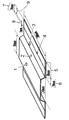
- Example 4 As a mold, a mold having a cavity for a hat-shaped molded body having a height of 10 mm described in FIG. 2 instead of FIG. 1 is used.
- the pin of the pinch part of the mold has a thickness of 1.3 mm and a pinch part.
- the width was set to 2 mm, and the same operation as in Example 1 was performed except that the molding material was cut into a rectangular shape of 700 mm ⁇ 150 mm. Similar to Example 1, a hat-shaped molded article having a good appearance could be obtained continuously.
- the cavity projected area 945 cm 2 the area of the pinching unit is 28cm 2
- the maximum pressure acting on the pinching part 49 MPa the maximum pressure of the cavity was 20 MPa.
- the clamping force was set to 1890 kN and a pressure of 20 MPa per cavity projected area.
- the pinching constant Kp (MPa ⁇ cm 2 / kN) was 0.08. Table 1 shows the evaluation results regarding the molding of this example.
- Example 5 The operation was performed in the same manner as in Example 1 except that a molding material having a reinforcing fiber (A) amount of 87 vol% in the total amount of reinforcing fibers was used. Similar to Example 1, a hat-shaped molded article having a good appearance could be obtained continuously. The maximum pressure in the pinching part was 32 MPa, and the pinching constant Kp (MPa ⁇ cm 2 / kN) was 0.23. Table 1 shows the evaluation results regarding the molding of this example.
- Example 6 The operation was performed in the same manner as in Example 1 except that a molding material having a reinforcing fiber (A) amount of 65 vol% in the total amount of reinforcing fibers was used. Similar to Example 1, a hat-shaped molded article having a good appearance could be obtained continuously. The maximum pressure in the pinching part was 38 MPa, and the pinching constant Kp (MPa ⁇ cm 2 / kN) was 0.28. Table 2 shows the results of evaluation regarding the molding of this example.
- the molding die is not the one shown in FIG. 1 but has a cavity shape corresponding to a 400 mm ⁇ 400 mm ⁇ 2.5 mm flat plate shaped body, and a 20 mm wide region on the entire outer periphery of the cavity is a substantially outer peripheral end.
- the product shape part substantially central part
- the operation was performed in the same manner as in Example 1 except that a pinch part having a thickness of 1.5 mm and a pinching width of 5 mm was used. Also in this example, it was possible to continuously obtain a molded article having a good appearance and having ears.
- the cavity area is 1600 cm 2
- the pinching area is 77 cm 2
- the maximum pressure in the pinching area is 38 MPa
- the maximum cavity pressure is 20 MPa
- the pinching constant Kp MPa ⁇ cm 2 / kN
- Example 8 The operation was performed in the same manner as in Example 1 except that a molding material having a reinforcing fiber (A) amount of 95 vol% in the total amount of reinforcing fibers was used.
- a hat-shaped molded article having a good appearance could be continuously obtained in the same manner as in Example 1, but the amount of molding material flowing out from the pinching part was slightly increased during press molding, and the obtained ear part was obtained.
- the thickness of the top surface decreased and a difference in thickness occurred between the top surface portion and the elevation surface portion. Furthermore, the surface transferability of the flange portion was lowered.
- the maximum pressure in the pinching part was 33 MPa, and the pinching constant Kp (MPa ⁇ cm 2 / kN) was 0.24. Table 2 shows the results of evaluation regarding the molding of this example.
- Example 9 The operation was performed in the same manner as in Example 1 except that the molding material having a reinforcing fiber (A) ratio of 55 vol% in the total amount of reinforcing fibers was used. Although a hat-shaped molded article having a good appearance could be continuously obtained in the same manner as in Example 1, the thickness of the top surface of the hat-shaped molded article having the obtained ears increased, and the vertical surface The thickness of the portion was reduced, and the appearance of the elevation portion was slightly deteriorated. Furthermore, the surface transferability of the flange portion was considerably lowered. The maximum pressure in the pinching part was 41 MPa, and the pinching constant Kp (MPa ⁇ cm 2 / kN) was 0.31. Table 2 shows the results of evaluation regarding the molding of this example.
- Example 10 The operation was performed in the same manner as in Example 1 except that the block of the mold was changed and the pinching part thickness was set to 0.5 mm, the pinching part width was set to 5 mm, and the pinching part area was 70 cm 2 . A hat-shaped molded article having a slightly good appearance could be continuously obtained.
- the maximum pressure at the pinching part was 110 MPa, the maximum cavity pressure was 12 MPa, and the pinching constant Kp (MPa ⁇ cm 2 / kN) was 0.41.
- Table 2 shows the results of evaluation regarding the molding of this example.
- Example 1 Except for press molding by the method of installing needle-shaped projections at a pitch of 100 mm on the block of the lower mold pinching part, starting the mold clamping after fixing the molding material heated and plasticized with a needle The same operation as in Example 1 was performed.
- the hat-shaped molded body having the obtained ear part has an extremely thin wall on the top surface, the wrinkle mark on the vertical surface part does not disappear and the appearance is poor, and the transferability of the flange part is also extremely It was lowered and it was hard to say that it was a good product. This is presumably because, in press molding, the molding material was fixed before the start of clamping, the molding material was not pulled in by clamping, and the molding material was significantly stretched by clamping. Table 3 shows the results of evaluation regarding molding of this comparative example.
- Example 2 As a molding die, a molding die in which a block of a part forming the lower mold pinching portion is flat, and a pressing block which is a working nesting that makes a stroke of 40 mm by clamping is installed in a part forming the upper mold pinching portion.
- the same operation as in Example 1 was performed except that the molding material was fixed at a position higher by 40 mm before the molding material was sandwiched between the upper die and the lower die by clamping. .
- the hat-shaped molded body having the obtained ear part has an extremely thin top surface part, the wrinkle marks on the vertical part do not disappear, and the appearance is poor, and the transferability of the flange part is extremely poor. It was something that was hard to say. This is presumably because, in press molding, the molding material was fixed before the start of clamping, the molding material was not pulled in by clamping, and the molding material was significantly stretched by clamping. Table 3 shows the results of evaluation regarding molding of this comparative example.
- Example 3 The same operation as in Example 1 was performed except that the molding material was cut into a rectangular shape of 700 mm ⁇ 140 mm. In continuous press molding, short shots occurred, and it was difficult to say that a molded body could be stably produced. The obtained hat-shaped molded body having the ear portion had a poor appearance in which a flow mark was generated at the end portion. This is because in press molding, the molding material was pushed by the upper mold and pulled into the recess of the lower mold almost simultaneously with the start of mold clamping, and the mold clamping was performed without fixing the end of the molding material at the pinching part. I think that the. Table 3 shows the results of evaluation regarding molding of this comparative example.
- the pinching part thickness was set to 2.5 mm, which is the same as the thickness at the substantial cavity (the thickness of the substantially central part of the cavity), and the molding material began to be drawn into the space around the convex part of the lower mold.
- the operation was performed in the same manner as in Example 1 except that both end portions of the molding material were not fixed by the pinching portion.
- the molding material can be stably produced due to the instability of drawing the molding material into the molding die at the start of mold clamping and the occurrence of short shots.
- the obtained hat-shaped molded body having the ear portion had extremely poor transferability at the flange portion. Table 3 shows the results of evaluation regarding molding of this comparative example.
- the production method of the present invention makes it possible to produce a fiber-reinforced resin molded article excellent in appearance with high mass productivity, and requires excellent physical properties such as structural parts such as automobiles and high cost competitiveness. Suitable for use.
Abstract
Description
このことから、非流動性成形材料を用いたオープンキャビティ法の成形より、流動性を有する成形材料をクローズドキャビティ法で成形することが経済的に好適である。しかしこのクローズドキャビティ法では二つの課題がある。
特許文献3には、連続繊維強化熱可塑性樹脂層の少なくとも片面の一部に、不連続繊維強化熱可塑性樹脂層が積層したシート材料をプレス成形し、繊維強化熱可塑性樹脂成形品を製造するための金型であって、キャビティの外周縁には、当該金型を閉めた時に前記不連続繊維強化熱可塑性樹脂層の前記キャビティ外への流出を防止する枠状の堰部が、前記連続繊維強化熱可塑性樹脂層を前記キャビティ外へと延出させる隙間を形成しつつ設けられている金型、および当該金型を用いて繊維強化熱可塑性樹脂成形品を製造すると、プレス成形時の型開きが困難になることが起き難く、バリの発生が抑制されることが示されている。しかし、特許文献3の発明においては、プレス成形時に不連続繊維強化熱可塑性樹脂層が可塑状態になり流動して金型の堰部で流動が止められて成形品形状の一部が形成されており、これは不連続繊維強化熱可塑性樹脂層に関しては実質的にクローズドキャビティ法の成形が行われていることを意味している。つまり、特許文献3の発明では、上記のクローズドキャビティ法の問題点は解決されていない。
特許文献4は、開口部とフランジ部とを有する凹部の型と、該凹部に対応する凸部を有し、該凹部の型との間でキャビティが構成される凸部の型からなる成形型を用いて、強化繊維と熱可塑性樹脂からなる成形材料(以下、特に注記無い場合はプレス成形材料を指す)、をプレス成形する方法であって、前記成形型の下面となる型の上に強化繊維と熱可塑性樹脂からなる、少なくとも下記2種類の形状を有する成形材料(A)、(B)を積層して配置する工程、前記成形型の下面となる型の上に積層、配置した成形材料(A)、(B)を前記成形型の上面となる型を用いて加圧する工程、を有するプレス成形方法を開示している。
成形材料(A):前記キャビティの有する最大面積以上の面積を有する形状。
成形材料(B):少なくとも前記凹部の開口部の投影面積以上の投影面積を有する形状。
更に、特許文献4の図8は、型締め時に成形材料を挟み込み固定する機構を示している。この機構は、上型が成形材料に接触する前に、成形材料を挟み固定する機構であり、型締めとともに固定する部位がスライドする機構である。この機構は、型締め時に、成形材料が引き込まれることを防止し、上層の成形材料がずれることを防いでいる。
この特許文献4の発明は、強化繊維と熱可塑性樹脂からなる成形材料を用いたプレス成形において、煩雑な工程を必要としない優れた作業性と、成形型の複雑形状に対し容易に追随させることができる優れた成形性とを兼ね備えたプレス成形方法であるとされている。
しかし、当該発明は、キャビティの有する最大面積以上の面積を有する形状の成形材料(A)、および、少なくとも前記凹部の開口部の投影面積以上の投影面積を有する形状成形材料(B)の2種類の成形材料を必要とする。成形材料(A)、成形材料(B)のいずれも、それらの定義から、目的の成形品の主要部に相当する大きさであることが分かる。主たる成形材料に、パッチ状の成形材料小片を部分的に積層させてプレス成形を行う程度ならそれほど煩瑣ではないかも知れない。しかし、特許文献4の発明のように、目的の成形品の主要部に相当するほどの大きさで、かつ、微妙に大きさが異なる2つの成形材料を用意し、それらを可塑状態にして特定の状態および条件で金型に配置してプレス成形を行う成形品の製造方法は相当に煩瑣であり、当該製造方法には作業性や量産性の面でかなりの改善の余地がある。
更に、本発明は、上記製造方法で得られる耳部を有する繊維強化樹脂成形体の耳部を切断する処理を含む、繊維強化樹脂加工品の製造方法に関する。
本発明は、強化繊維とマトリクスとしての熱可塑性樹脂とを含む成形材料を、上型と下型とを有する成形型にて型締めしプレス成形することによる、繊維強化樹脂成形体の製造方法であって、加熱され可塑状態にある(本発明に関し、「熱可塑状態にある」または「可塑状態にある」と簡略に称することがある)成形材料を上型と下型との間に配置し、型締めを開始して、該成形材料のある部位に、略型締め方向への力を作用させ、該成形材料を略型締め方向へ変形させ始めてから、該成形材料の略外周端部の少なくとも一部ではあるが前記のある部位とは異なる固定用部位に、略型締め方向への力を作用させて、該固定用部位を押して、好ましくは潰しつつ、固定した後、型締めを完了し、耳部を有する繊維強化樹脂成形体を得ることを特徴とする製造方法に関する。ここで、繊維強化樹脂成形体が有する耳部は、プレス成形において、該成形材料の上記固定用部位が、略型締め方向への力を作用され固定されてから型締めが完了することにより形成される。略型締め方向へ力が作用されるとは、成形型の上型から下型への方向、下型から上型への方向、またはその双方向のいずれに力が作用されるものであっても良い。
本発明により、外観性に優れる繊維強化樹脂成形体を高い量産性にて製造することが可能となり、かつ、成形における成形型から成形体への表面転写性が優れているので、表面に微細な模様や複雑な模様を表面に有する繊維強化樹脂成形体の製造も極めて容易になる。上記これは、従来のプレス成形技術で、成形材料の端部を固定してから型締めを行うとの手法が良好な成形体を得るために好適とされてきたことからは極めて予想し難い効果である。
成形材料の加熱温度は、成形材料が可塑状態となる温度以上の温度であり、具体的にはマトリクスである熱可塑性樹脂が非晶性樹脂の場合はガラス転移温度以上の温度、結晶性樹脂の場合は、融点以上の温度に加熱される。この時、重要なのは成形材料の略外周端部の固定用部位を型締め完了より先に押し、好ましくは押し潰し固定化することである。この押しつぶし固定化する手法としては、上型にスライド機構を用いて押し潰し部のスライドブロックを機械的移動させに型締めより先に成形材料に接触させ潰す機構などが考えられるが、本発明における方法としては、成形用金型を用いて金型の開閉動作で成形材料略外周端部を押し、好ましくは潰しつつ、固定する手法が好ましい。具体的には、入れ子構造で取り外しや交換が可能なブロックなどを用いてキャビティの略外周端部に、キャビティの略中央部より厚みが小さいピンチング部が形成される成形用金型を用いて、可塑状態にある成形材料の略外周端部の少なくとも一部である固定用部位が、型締め時にキャビティのピンチング部で挟み込まれるように、該成形材料を成形型に配置することにより、型締め動作にて成形材料の上記固定用部位、好ましくは外周部をキャビティ部の圧縮が開始となる前に押し、好ましくは押し潰し固定化することが可能となる。
{ピンチング部最大圧力(MPa)×ピンチング部面積(cm2)/10)}/型締め力(kN)=ピンチング定数Kp(MPa・cm2/kN) (p)
このピンチング部に作用する圧力については、具体的には、金型ピンチング部面に設置された圧力センサーによって実測値を計測可能である。このピンチング部圧力を調整する方法としては、ピンチング部の上型下型のクリアランスを調整することが例示される。ピンチング部のクリアランスの好ましい大きさは用いる成形材料に大きく依存する。強化繊維量が少なく流動性が良好である成形材料では必要なクリアランスは狭くなり、逆に強化繊維量が多くまた強化繊維が絡み合って流動しにくい成形材料では必要なクリアランスは広くなる。成形材料からピンチング部のクリアランス量の見当をつける具体的かつ簡易的な方法として、30mm角程度の成形材料を所定の成形条件にて圧縮し押し潰し、得られた押し潰し片の肉厚から推測する方法が例示される。この場合、得られた押し潰し片の厚みの70%から100%、好ましくは80%から90%の大きさでクリアランスを設定することが望ましい。
本発明の製造方法は、固定用部位を適切に設計することにより、オープンキャビティ法プレス成形では得難い、耳部が小さい耳部付き成形体を与えることができる。
本発明で用いる強化繊維と、マトリクスとしての熱可塑性樹脂とを含む成形材料(本発明に関して、繊維強化樹脂材と称することがある)としては、公知のものを好ましく用いることができる。
繊維強化樹脂材中におけるマトリクスとしての熱可塑性樹脂の存在量は、熱可塑性樹脂の種類や強化繊維の種類等に応じて適宜決定することができるものであり、特に限定されるものでは無い。通常、強化繊維100重量部に対して熱可塑性樹脂が3重量部~1000重量部の範囲内であると好ましく、より好ましくは30~200重量部であり、更に好ましくは30~150重量部である。マトリクスとしての熱可塑性樹脂の量が強化繊維100重量部に対し3重量部以上ならば繊維強化樹脂材において樹脂含浸が十分になりドライの強化繊維が少なくなる。マトリクスとしての熱可塑性樹脂の量が1000重量部を以下であると強化繊維の量が充分で、構造材料として適切となることが多い。なお、本発明に関して、便宜上、重量との用語を用いることがあるが、実際には質量のことである。
本発明で用いられる繊維強化樹脂材における強化繊維の配向状態は、上記の一方向配向又は2次元ランダム配向のいずれであってもよい。上記一方向配向と2次元ランダム配向の中間の無規則配向(強化繊維の長軸方向が完全に一方向に配向しておらず、かつ完全にランダムでない配向状態)であってもよい。強化繊維の繊維長によっては、強化繊維の長軸方向が繊維強化樹脂材の面内方向に対して角度を有するように配向していてもよく、強化繊維が綿状に絡み合うように配向していてもよく、強化繊維が平織や綾織などの二方向織物、多軸織物、不織布、マット、ニット、組紐、強化繊維を抄紙した紙等のように配向していてもよい。
繊維強化樹脂材や耳部付き成形体に含まれる強化繊維が2次元ランダム配向であることについて、特に数値的に定義したい場合は、日本国特開2012-246428号公報に示されているように、強化繊維に関して、面配向度σ=100×(1-(面配向角γが10°以上の強化繊維本数)/(全強化繊維本数))で定義される面配向度σが90%以上である状態を好ましい2次元ランダム配向としてもよい。
更に、成形体試料を厚み方向に切断した断面における任意の矩形領域について、成形体の厚み方向または成形体の厚み方向とは異なる方向をZ方向とし、上記公報に準じて強化繊維に関する観察、測定および面配向度σの算出を行っても良い。その場合、面配向角γの算出に必要な、強化繊維断面の長径と成形板表面が成す角については、成形板表面ではなく、観察対象の矩形領域の上辺または下辺と、強化繊維断面の長径とが成す角を用いても良い。
繊維強化樹脂材における強化繊維の目付量は、特に限定されるものではないが、通常、下限値は25g/m2~10000g/m2とされる。繊維強化樹脂材をプレス成形して耳部付き成形体を製造する際、特に強化繊維や成形材料の追加がされなければ、繊維強化樹脂材における強化繊維の目付量を、得られる耳部付き成形体における強化繊維の目付量とみなすことができる。
本発明に用いられる繊維強化樹脂材が複数の層が積層された構成を有する場合、上記厚みは各層の厚みを指すのではなく、各層の厚みを合計した繊維強化樹脂全体の厚みを指すものとする。
繊維強化樹脂材が上記積層構造を有する態様としては、同一の組成を有する複数の層が積層された態様であってもよく、又は互いに異なる組成を有する複数の層が積層された態様であってもよい。
3層以上が積層される場合には、任意のコア層と、当該コア層の表裏面上に積層されたスキン層とからなるサンドイッチ構造としてもよい。
本発明で用いる繊維強化樹脂材中には、本発明の目的を損なわない範囲で、有機繊維または無機繊維の各種繊維状または非繊維状のフィラー、難燃剤、耐UV剤、安定剤、離型剤、顔料、軟化剤、可塑剤、界面活性剤等の添加剤を含んでいてもよい。
Vf=100×強化繊維体積/(強化繊維体積+熱可塑性樹脂体積) 式(u)
別途示したとおり、成形材料を成形して耳部付き成形体を得る場合、成形において、当該成形材料のほかに、他の成形材料、強化繊維、または熱可塑性樹脂などを添加することがなければ、成形材料のVfを耳部付き成形体のVfとみなすことができる。
εv(%)=100×成形材料の伸長後の長さ/成形材料の伸長前の長さ (e)
より具体的には、成形材料を、そのマトリックスとしての熱可塑性樹脂の軟化温度以上の温度まで昇温して、引張破断伸度εv測定用のプレス成形用の成形型の上に成形材料を配置し、成形型締め付け速度20mm/secで、成形材料を破断させるまで成形型を閉じた後、成形材料を取り出して成形材料が伸長した長さを測定し、成形材料の伸長前の長さで除算して計算される。
本発明の耳部を有する繊維強化樹脂成形体や繊維強化樹脂材に含まれる強化繊維として好ましいものは炭素繊維であるが、マトリクス樹脂の種類や繊維強化樹脂材の用途等に応じて、炭素繊維以外の無機繊維又は有機繊維のいずれも用いることができる。
上記炭素繊維以外の無機繊維としては、例えば、活性炭繊維、黒鉛繊維、ガラス繊維、タングステンカーバイド繊維、シリコンカーバイド繊維(炭化ケイ素繊維)、セラミックス繊維、アルミナ繊維、天然繊維、玄武岩などの鉱物繊維、ボロン繊維、窒化ホウ素繊維、炭化ホウ素繊維、及び金属繊維等を挙げることができる。
上記ガラス繊維としては、Eガラス、Cガラス、Sガラス、Dガラス、Tガラス、石英ガラス繊維、ホウケイ酸ガラス繊維等からなるものを挙げることができる。
上記有機繊維としては、例えば、アラミド、PBO(ポリパラフェニレンベンズオキサゾール)、ポリフェニレンスルフィド、ポリエステル、アクリル、ポリアミド、ポリオレフィン、ポリビニルアルコール、ポリアリレート等の樹脂材料からなる繊維を挙げることができる。
本発明においては、2種類以上の強化繊維を併用してもよい。この場合、複数種の無機繊維を併用してもよく、複数種の有機繊維を併用してもよく、無機繊維と有機繊維とを併用してもよい。
上記炭素繊維としては、一般的にポリアクリロニトリル(PAN)系炭素繊維、石油ピッチ系炭素繊維、石炭ピッチ系炭素繊維、レーヨン系炭素繊維、セルロース系炭素繊維、リグニン系炭素繊維、フェノール系炭素繊維、気相成長系炭素繊維などが知られているが、本発明においてはこれらのいずれの炭素繊維であっても好適に用いることができる。
強化繊維とマトリクス樹脂との密着強度は、ストランド引張せん断試験における強度が5MPa以上であることが望ましい。この強度は、マトリクス樹脂の選択に加え、例えば強化繊維が炭素繊維である場合、表面酸素濃度比(O/C)を変更する方法や、炭素繊維にサイジング剤を付与して、炭素繊維とマトリクス樹脂との密着強度を高める方法などで改善することができる。
本発明において、単繊維束状の強化繊維を用いる場合、各単繊維束を構成する単繊維の数は、各単繊維束においてほぼ均一であってもよく、あるいは異なっていてもよい。
本発明に用いられる強化繊維としては、上記のとおり強度や寸法の面内等方性に優れる重量平均繊維長100mm以下の不連続繊維だけでなく、目的に応じて連続繊維を用いてもよい。
強化繊維の平均繊維長は、例えば、繊維強化樹脂材から無作為に抽出した100本の繊維の繊維長を、ノギス等を用いて1mm単位まで測定し、下記式(m)および式(f)に基づいて求めることができる。繊維強化樹脂材からの強化繊維の抽出法は、例えば、繊維強化樹脂材に500℃×1時間程度の加熱処理を施し、炉内にて樹脂を除去することによって行うことができる。
個数平均繊維長Ln=ΣLi/j (m)
(ここで、Liは強化繊維の繊維長、jは強化繊維の本数である)
重量平均繊維長Lw=(ΣLi2)/(ΣLi) (f)
(ここで、Liは強化繊維の繊維長である)
なお、ロータリーカッターで切断した場合など、繊維長が一定長の場合は個数平均繊維長を重量平均繊維長とみなせる。
本発明に用いられる強化繊維の単繊維径は、強化繊維の種類に応じて適宜決定すればよく、特に限定されるものではない。
強化繊維として炭素繊維が用いる場合、平均単繊維径は、通常、3μm~50μmの範囲内であることが好ましく、4μm~12μmの範囲内であることがより好ましく、5μm~8μmの範囲内であることがさらに好ましい。
ここで、上記平均単繊維径は、その名のとおり強化繊維の単繊維の直径を指すものであるが、強化繊維が単繊維の束状物である場合は、平均単繊維径を平均繊維径と略称することもある。
強化繊維の平均単繊維径は、例えば、JIS R7607(2000)に記載された方法によって測定することができる。
強化繊維束としては、複数の単繊維が凡そ同方向を向き、それらの長手側面同士が接して束状になっているものが代表的だが、この形態に限定されない。例えば、複数の単繊維が様々な方向を向いた束状であってもよく、複数の単繊維が長手側面の一部では近接しているが、それ以外の部分では単繊維の間が離れているような束状であってもよい。本発明に用いられる強化繊維が単繊維束状である場合、各単繊維束を構成する単繊維の数は特に限定されるものではないが、通常、2本~10万本の範囲内とされる。
臨界単繊維数=600/D (1)
(ここでDは強化単繊維の平均単繊維径(μm)である)
で定義する臨界単繊維数以上の本数の単繊維で構成される強化繊維(A)について、強化繊維全量に対する割合が20vol%以上となる量であることが好ましく、30vol%以上となる量であることがより好ましく、更に好ましくは40vol%以上であり、特に好ましくは50vol%以上となる量である。強化繊維(A)以外の強化繊維として、単繊維の状態または臨界単繊維数未満の本数の単繊維で構成される単繊維束、以下、強化繊維(B)と称する場合がある、が存在してもよい。本発明で用いられる強化繊維については、特定の単繊維数以上で構成される強化繊維(A)の厚みを低減させ、かつ強化繊維単位重量(g)当たりの強化繊維(A)の束数を特定の範囲とすることで繊維強化樹脂材の厚み斑を小さくできるため、そのような強化繊維を含む繊維強化樹脂材を成形することで薄肉でも機械物性に優れた繊維強化樹脂成形体を得ることが可能である。
前記のとおり、強化繊維(A)は強化単繊維の束状物であるので、便宜上、強化繊維束(A)と称されることもある。同様に、強化繊維(A)の平均単繊維数が平均繊維数と略称されることがある。
本発明に関する耳部付き成形体や繊維強化樹脂材においては、マトリクス樹脂として熱可塑性樹脂が含まれている。また、本発明においてはマトリクス樹脂として、熱可塑性樹脂を主成分とする範囲において、熱硬化性樹脂を併用してもよい。
上記熱可塑性樹脂は特に限定されるものではなく、耳部付き成形体やその加工品の用途等に応じて所望の軟化温度を有するものを適宜選択して用いることができる。
上記熱可塑性樹脂としては、通常、軟化温度が180℃~350℃の範囲内のものが好ましく用いられるが、これに限定されるものではない。本発明について熱可塑性樹脂の軟化温度とは、結晶性熱可塑性樹脂については結晶溶解温度、いわゆる融点であり、非晶性熱可塑性樹脂についてはガラス転移温度である。
上記ポリスチレン樹脂としては、例えば、ポリスチレン樹脂、アクリロニトリル-スチレン樹脂(AS樹脂)、アクリロニトリル‐ブタジエン‐スチレン樹脂(ABS樹脂)等からなる群より選ばれる1種類以上のものを挙げることができる。
上記ポリアミド樹脂としては、例えば、ポリアミド6樹脂(ナイロン6)、ポリアミド11樹脂(ナイロン11)、ポリアミド12樹脂(ナイロン12)、ポリアミド46樹脂(ナイロン46)、ポリアミド66樹脂(ナイロン66)、ポリアミド610樹脂(ナイロン610)等からなる群より選ばれる1種類以上のものを挙げることができる。
上記ポリエステル樹脂としては、例えば、ポリエチレンテレフタレート樹脂、ポリエチレンナフタレート樹脂、ボリブチレンテレフタレート樹脂、ポリトリメチレンテレフタレート樹脂、液晶ポリエステル等を挙げることができる。
上記変性ポリフェニレンエーテル樹脂としては、例えば、変性ポリフェニレンエーテル等を挙げることができる。
上記熱可塑性ポリイミド樹脂としては、例えば、熱可塑性ポリイミド、ポリアミドイミド樹脂、ポリエーテルイミド樹脂等を挙げることができる。
上記ポリスルホン樹脂としては、例えば、変性ポリスルホン樹脂、ポリエーテルスルホン樹脂等からなる群より選ばれる1種類以上のものを挙げることができる。
上記ポリエーテルケトン樹脂としては、例えば、ポリエーテルケトン樹脂、ポリエーテルエーテルケトン樹脂、ポリエーテルケトンケトン樹脂からなる群より選ばれる1種類以上のものを挙げることができる。
上記フッ素系樹脂としては、例えば、ポリテトラフルオロエチレン等を挙げることができる。
本発明に用いられる繊維強化樹脂材は、公知の方法を用いて製造することができる。
マトリクス樹脂として熱可塑性樹脂を用いる場合は、例えば、1.強化繊維をカットする工程、2.カットされた強化繊維を開繊させる工程、3.開繊させた強化繊維と繊維状又は粒子状のマトリクス樹脂を混合し等方性基材とした後、これを加熱圧縮して熱可塑性樹脂の含浸をすすめ繊維強化樹脂材を得る工程により製造することができるが、この限りではない。
等方性基材(2次元ランダム配向マットとも呼ばれる)およびその製造法については、WO2012/105080パンフレット、特開2013-49298号公報の明細書に詳しく記載されている。
A(極めて良好):金型表面が十分に転写され、表面に光沢差もなく均一で平滑な状態である。
B(良好):金型表面が転写されているが、Aより若干光沢が低下しており、表面に若干な光沢差または炭素繊維の状態に差があり異なる外観の領域を確認できる。
C(やや良好):金型表面の転写が部分的に不十分で、まだら模様の外観となっており、表面光沢が失われた部位と光沢がある部位とが明確に認識できる。
D(不良):一部製品肉厚が減少し、まったく金型面を転写しておらず、光沢が失われた部位の表面状態は荒れている。
(成形型および成形体形状)
図1および図2に示したようなそれぞれ高さ30mm、10mm、厚みはいずれも2.5mmのハット形状断面の成形体に相当するキャビティが形成される、上型と下型からなる成形型を用いてプレス成形を行った。この成形型において成形体のフランジ部に相当する部分(フランジ相当部)の幅は40mmであり、そのうち幅20mmの部分はキャビティの略中央部の一部と解される肉厚2.5mmの領域であり、残りの幅20mmがキャビティのピンチング部を含む領域である。成形型において、ピンチング部を形成する部位は入れ子構造となっているブロックからなっており、そのブロックを交換することにより、ピンチング部の厚みや幅を調整することが可能である。
成形体および成形型キャビティ形状における幅について、詳細に定義するならば、当該成形型を用いた成形で得られる成形体の長手方向をXYZ座標系のY軸方向、高さをZ軸方向とした場合のX軸方向の成形体寸法が、幅である。
一部の実施例などで、400mm×400mmの平板形状の成形体に相当するキャビティ形状を有する成形型(以下、平板状成形型と称することがある)を用いた。
成形材料を、そのマトリックスとしての熱可塑性樹脂の軟化温度以上の温度まで昇温して、引張破断伸度εv測定用のプレス成形用の成形型の上に成形材料を配置し、成形型締め付け速度20mm/secで、成形材料を破断させるまで成形型を閉じた後、成形材料を取り出して成形材料が伸長した長さを測定し、成形材料の伸長前の長さで除算して、つまり下記式(e)にて計算される。
εv(%)=100×成形材料の伸長後の長さ/成形材料の伸長前の長さ (e)
本出願では、川崎油工株式会社製の油圧式5000kNプレス機を用いた。特に記載が無い限り、成形条件は同一であり、具体的には、後述の成形型を取り付け、加圧圧力15MPa、成形型温度150℃、成形材料の加熱温度は290℃で型締め、つまりプレス成形を実施した。
[製造例1]成形材料の製造
強化繊維として、東邦テナックス社製のPAN系炭素繊維“テナックス”(登録商標)STS40-24KS(平均単繊維径7μm、単繊維数24000本)をナイロン系サイジング剤処理したものを使用し、マトリクス樹脂として、ユニチカ社製のナイロン6樹脂A1030(融点:225℃)を用いて、WO2012/105080パンフレットに記載された方法に準拠し、重量平均繊維長が20mmの炭素繊維が2次元ランダム配向していて、炭素繊維目付1800g/m2である面内等方性基材を作成した。この得られた面内等方性基材を、250℃に設定された平板状成形型に投入し、2MPaで10分間加圧した後、成形型温度を100℃まで下げ、炭素繊維が2次元ランダム配向しているマット構造に、ナイロン6樹脂が充分に含浸した、厚み2.6mmの平板状の面内等方性の成形材料を得た。この成形材料の強化繊維体積割合(Vf)は35%、含有する強化繊維の重量平均繊維長は20mmであり、臨界単繊維数は86本であり、強化繊維全量のうち、臨界単繊維数以上の本数の炭素単繊維からなる強化繊維(A)の量の割合は77vol%であった。成形材料中の、強化繊維(A)以外の強化繊維として、臨界単繊維数未満の本数の炭素単繊維からなる束、および単繊維状の炭素繊維も存在した。この成形材料は、前記式(e)により求められる引張破断伸度εvが105%~400%の範囲にあるものである。
製造例1にて得られた、厚み2.6mmの成形材料を700mm×190mmの矩形型にカットしたものを用いて、以下の手順にてプレス成形(20ショット連続成形)を行った。
成形型として、高さ30mmのハット形状成形体(図1)に対応する形状のキャビティを有する成形型を用いた。この成形型のピンチング部のブロックは、隙間(ピンチング部)厚み1.5mm、ピンチング部の幅がキャビティの略中央部の端から10mmになるように設定されたものであった。
加熱され可塑状態にある成形材料を、その幅方向の両端部が、成形型キャビティのピンチング部で挟みこまれるように成形型の下型の上に設置して、成形型の型締めを始めた。まず、成形材料の中央部周辺(略中央部)が、上型の凹部により下型の凸部周辺の空間に引き込まれてから、成形材料の両端部は型締めによりキャビティのピンチング部で押され、かつ潰されながら固定され、更に型締めが進むと、成形材料の両端部はピンチング部で固定されたままずれることなく、成形材料はキャビティ形状どおりのハット形状となった。型締めが完了し、充分に成形材料が冷却され固化したと判断されてから、成形型を開き、型締め時に、成形材料の両端部、つまり、プレス成形時にキャビティのピンチング部で挟み込まれた部分(幅10mm)およびその外側の部分が耳部となった、耳部を有するハット形状の繊維強化樹脂成形体(以下、ハット形状成形体と略称することがある)を得た。ハット形状成形体の耳部は、その幅方向の両端からそれぞれ20mmの幅の部位となった。
ピンチング部に作用する最大圧力(MPa)、ピンチング面積(cm2)、型締め力(kN)から前記式(p)で定義されるピンチング定数Kp(MPa・cm2/kN)は0.28であった。上記のように得られた耳部を有するハット形状成形体の耳部をエンドミルにより切削し繊維強化樹脂加工品を得た。
得られた繊維強化樹脂加工品について観察、測定を行ったところ、その端部の外観は、流動跡、転写不良などなく良好であった。また製品フランジ部に設置された設計半径300μmの半球状突起の高さは280μmと表面転写性も良好であった。ハット状成形体の天面の肉厚2.4mmに対し、立面の肉厚も2.4mmでキャビティどおりの均一な厚みであり、立面にはしわの跡もなくハット状成形体全体が良好な外観であった。上記の観察、測定結果は耳部が切削される前のハット形状成形体についても当てはまることは明らかである。
本実施例の成形に関する評価の結果について表1に示す。
成形型のブロックを変更し、ピンチング部厚み1.3mm、ピンチング部の幅を5mm、ピンチング部の面積70cm2に設定した以外は実施例1と同様に操作を行った。実施例1と同様に良好な外観のハット形状成形体を連続して得ることができた。ピンチング部の最大圧力は56MPa、キャビティ最大圧力は20MPaであり、ピンチング定数Kp(MPa・cm2/kN)は0.20であった。
本実施例の成形に関する評価の結果について表1に示す。
成形型のブロックを変更し、ピンチング部厚み1.0mm、ピンチング部の幅を3mm、ピンチング部の面積42cm2に設定した以外は、実施例1と同様に操作を行った。実施例1と同様に良好な外観のハット形状成形体を連続して得ることができた。ピンチング部の最大圧力73MPa、キャビティ最大圧力は20MPaであり、ピンチング定数Kp(MPa・cm2/kN)は0.16であった。
本実施例の成形に関する評価の結果について表1に示す。
成形型として、図1ではなく図2に記載の高さ10mmのハット形状成形体用のキャビティを有する成形型を用い、成形型のピンチング部のブロックを、ピンチング部の厚み1.3mm、ピンチング部の幅が2mmになるように設定し、成形材料を700mm×150mmの矩形型にカットして用いた以外は、実施例1と同様に操作を行った。実施例1と同様に良好な外観のハット形状成形体を連続して得ることができた。なお、キャビティ投影面積は945cm2、ピンチング部の面積は28cm2、ピンチング部に作用する最大圧力は49MPa、キャビティ部の最大圧力は20MPaであった。なお、型締め力は1890kNとし、キャビティ投影面積当たり20MPaの圧力となるように設定した。ピンチング定数Kp(MPa・cm2/kN)は0.08であった。
本実施例の成形に関する評価の結果について表1に示す。
強化繊維全量のうち強化繊維(A)の量の割合は87vol%である成形材料を用いた以外は実施例1と同様に操作を行った。実施例1と同様に良好な外観のハット形状成形体を連続して得ることができた。ピンチング部の最大圧力は32MPaとなり、ピンチング定数Kp(MPa・cm2/kN)は0.23であった。
本実施例の成形に関する評価の結果について表1に示す。
強化繊維全量のうち強化繊維(A)の量の割合は65vol%である成形材料を用いた以外は実施例1と同様に操作を行った。実施例1と同様に良好な外観のハット形状成形体を連続して得ることができた。ピンチング部の最大圧力は38MPaとなり、ピンチング定数Kp(MPa・cm2/kN)は0.28であった。
本実施例の成形に関する評価の結果について表2に示す。
成形型として、図1に記載のものでなく、400mm×400mm×2.5mmの平板形状の成形体に相当するキャビティ形状を有し、キャビティの全外周の20mm幅の領域が略外周端部であり、製品形状部(略中央部)は360mm平方であり、ブロックによりピンチング部の厚み1.5mm、ピンチング幅5mmに調整されたものを用いた以外は実施例1と同様に操作を行った。本実施例においても、良好な外観の、耳部を有する成形体を連続して得ることができた。なお、プレス成形において、キャビティ面積は1600cm2、ピンチング部の面積は77cm2であり、ピンチング部の最大圧力は38MPa、キャビティ最大圧力は20MPaであり、ピンチング定数Kp(MPa・cm2/kN)は0.09であった。
本実施例の成形に関する評価の結果について表2に示す。
強化繊維全量のうち強化繊維(A)の量の割合は95vol%である成形材料を用いた以外は実施例1と同様に操作を行った。実施例1と同様に良好な外観のハット形状成形体を連続して得ることができたが、プレス成形時に、ピンチング部から流出する成形材料の量が若干増加し、得られた耳部を有するハット形状成形体についても、その天面の肉厚が減少して天面部と立面部で肉厚に差が発生した。更に、フランジ部の表面転写性が低下した。ピンチング部の最大圧力は33MPaとなり、ピンチング定数Kp(MPa・cm2/kN)は0.24であった。
本実施例の成形に関する評価の結果について表2に示す。
強化繊維全量のうち強化繊維(A)の量の割合は55vol%である成形材料を用いた以外は実施例1と同様に操作を行った。実施例1と同様に良好な外観のハット形状成形体を連続して得ることができたが、得られた耳部を有するハット形状成形体について、その天面の肉厚が増加し、立面部の肉厚が減少しており、かつ立面部の外観が若干悪化していた。更に、フランジ部の表面転写性がかなり低下した。ピンチング部の最大圧力は41MPaとなり、ピンチング定数Kp(MPa・cm2/kN)は0.31であった。
本実施例の成形に関する評価の結果について表2に示す。
成形型のブロックを変更し、ピンチング部厚み0.5mm、ピンチング部の幅を5mm、ピンチング部の面積70cm2に設定した以外は、実施例1と同様に操作を行った。やや良好な外観のハット形状成形体を連続して得ることができた。ピンチング部の最大圧力110MPa、キャビティ最大圧力は12MPaであり、ピンチング定数Kp(MPa・cm2/kN)は0.41であった。
本実施例の成形に関する評価の結果について表2に示す。
下型のピンチング部のブロックに針状の突起を100mmピッチで設置し、加熱され可塑状態にした成形材料を針で突き刺し固定化した後に型締めを始めるとの手法でプレス成形を行った以外は、実施例1と同様に操作を行った。得られた耳部を有するハット形状成形体は、天面部の肉厚が極端に薄くなり、立面部のシワ跡も消滅せず外観が不良のもので、そのフランジ部の転写性も極端に低下したものであり、良品とは言い難いものであった。これは、プレス成形において、成形材料の固定が型締め開始前にされていて、型締めによる成形材料の引き込みが発生せず、型締めによって成形材料が著しく引き延ばされたためと思われる。
本比較例の成形に関する評価の結果について表3に示す。
成形型として、下型のピンチング部を形成する部位のブロックが平坦形状で、上型のピンチング部を形成する部位に、型締めによって40mmストロークする稼働入れ子である押さえブロックが設置された成形型を用い、プレス成形において、型締めにより上型と下型とで成形材料が挟み込まれる前の40mm上位の位置で成形材料が固定されるようにした以外は、実施例1と同様に操作を行った。得られた耳部を有するハット形状成形体は、天面部の肉厚が極端に薄く、立面部のシワ跡も消滅せず外観が不良のもので、そのフランジ部の転写性も極端に悪いものであり、良品とは言い難いものであった。これは、プレス成形において、成形材料の固定が型締め開始前にされていて、型締めによる成形材料の引き込みが発生せず、型締めによって成形材料が著しく引き延ばされたためと思われる。
本比較例の成形に関する評価の結果について表3に示す。
成形材料を700mm×140mmの矩形型にカットして用いた以外は、実施例1と同様に操作を行った。連続でのプレス成形ではショートショットが発生し、安定的に成形体を製造できているとは言い難かった。得られた耳部を有するハット形状成形体は、その端部で流動跡が発生している外観が不良のものであった。これは、プレス成形において、型締め開始とほぼ同時に成形材料が上型で押され下型の凹部に引き込まれ、成形材料の端部がピンチング部で固定されることなくそのまま型締めが行われたためと思われる。
本比較例の成形に関する評価の結果について表3に示す。
成形型のキャビティについて、ピンチング部厚みを、実質キャビティでの厚み(キャビティの略中央部の厚み)と同じ2.5mmに設定し、下型の凸部周辺の空間に成形材料が引き込まれ始めた後でも成形材料の両端部がピンチング部で固定されないようにした以外は、実施例1と同様に操作を行った。連続でのプレス成形では、型締め開始時の成形型への成形材料の引き込みが不安定になり、かつ、ショートショットが発生し安定的に成形体を製造できているとは言い難かった。得られた耳部を有するハット形状成形体はフランジ部での転写性が極めて悪いものであった。
本比較例の成形に関する評価の結果について表3に示す。


本発明を詳細にまた特定の実施態様を参照して説明したが、本発明の精神と範囲を逸脱することなく様々な変更や修正を加えることができることは当業者にとって明らかである。
本出願は、2016年1月8日に出願された日本特許出願(特願2016-003024号)に基づくものであり、その内容の全てが参照として本出願に組み込まれる。
2 ハット形状成形体の立面の肉厚の測定箇所
3 プレス成形時に、成形型のキャビティ部圧力が測定された箇所
4 プレス成形時に、成形型のピンチング部圧力が測定された箇所
5 フランジ部(の幅)
6 製品フランジ部(の幅)
7 耳部(の幅)
8 ハット形状成形体の耳部で、プレス成形時に成形材料がピンチング部で押された領域に相当する部位(の幅)
9 ハット形状成形体の耳部で、プレス成形時に成形材料がピンチング部で押された領域より外側の領域に相当する部位(の幅)
10 上型
11 下型
12 成形材料
13 ピンチング部
14 略中央部(製品形状部)
15 ハット状成形体(耳部付き成形体)
Claims (9)
- 強化繊維とマトリクスとしての熱可塑性樹脂とを含む成形材料を、上型と下型とを有する成形型にて型締めしプレス成形することによる、繊維強化樹脂成形体の製造方法であって、加熱され可塑状態にある成形材料を上型と下型との間に配置し、型締めを開始して、該成形材料のある部位に、略型締め方向への力を作用させ、該成形材料を略型締め方向へ変形させ始めてから、該成形材料の略外周端部の少なくとも一部ではあるが前記のある部位とは異なる固定用部位に、略型締め方向への力を作用させて、該固定用部位を押して固定した後、型締めを完了し、耳部を有する繊維強化樹脂成形体を得ることを特徴とする製造方法。
- 成形型として、型締めされた時に、上型と下型によりキャビティが形成され、かつ該キャビティの略外周端部に、該キャビティの略中央部より厚みが小さいピンチング部が形成される成形型を用い、可塑状態にある成形材料の略外周端部の少なくとも一部が、型締め時にキャビティのピンチング部で挟み込まれるように、該成形材料を成形型に配置することにより、該成形材料の略外周端部の固定用部位へ略型締め方向への力を作用させる、請求項1記載の繊維強化樹脂成形体の製造方法。
- 型締めにおける、ピンチング部に作用する最大圧力(MPa)、ピンチング面積(cm2)、型締め力(kN)から下式(p)で定義されるピンチング定数Kp(MPa・cm2/kN)が0.5未満である請求項2記載の繊維強化樹脂成形体の製造方法。
{ピンチング部最大圧力(MPa)×ピンチング部面積(cm2)/10)}/型締め力(kN)=ピンチング定数Kp(MPa・cm2/kN) (p) - キャビティが、略型締め方向に対する略垂直方向からみたキャビティ断面形状において、平面状部と非平面状部を有するものであり、
平面状部の表面と、該表面に連なる非平面状部表面との、略型締め方向の位置間距離が、キャビティの略中央部の厚みより大きい、請求項2または3に記載の繊維強化樹脂成形体の製造方法。 - 強化繊維全量のうち、下記式(1)で定義される臨界単繊維数以上の本数の単繊維の束である強化繊維(A)の量の割合が60vol%~90vol%であることを特徴とする請求項1~4のいずれか1項に記載の繊維強化樹脂成形体の製造方法。
臨界単繊維数=600/D (1)
(ここでDは強化繊維の平均単繊維径(μm)である) - 強化繊維の重量平均繊維長が0.1mm~500mmである請求項1~5のいずれかに記載の繊維強化樹脂成形体の製造方法。
- 成形材料および繊維強化樹脂成形体の双方において、強化繊維が2次元ランダム配向している請求項1~6のいずれか1項に記載の繊維強化樹脂成形体の製造方法。
- 成形材料および繊維強化樹脂成形体の少なくともいずれかにおいて、強化繊維及び熱可塑性樹脂について、下記式(u)
強化繊維体積割合Vf=100×強化繊維体積/(強化繊維体積+熱可塑性樹脂体積) (u)
で定義される強化繊維体積割合Vfが5%~80%である請求項1~7のいずれか1項に記載の繊維強化樹脂成形体の製造方法。 - 成形材料の下記式(e)で定義される引張破断伸度εvが105%~400%である、請求項1~8のいずれか1項に記載の繊維強化樹脂成形体の製造方法。
εv(%)=100×成形材料の伸長後の長さ/成形材料の伸長前の長さ (e)
ここで、成形材料の伸長後の長さとは、成形材料のマトリックスとしての熱可塑性樹脂の軟化温度以上の温度で、引張速度20mm/secで伸長された成形材料の長さであり、成形材料の伸長前の長さと同じ単位で表されたものである。
[請求項10]
請求項1~9のいずれか1項に記載の製造方法で得られる耳部を有する繊維強化樹脂成形体の耳部を切削する処理を含む、繊維強化樹脂加工品の製造方法。
Priority Applications (3)
| Application Number | Priority Date | Filing Date | Title |
|---|---|---|---|
| US16/068,538 US10889076B2 (en) | 2016-01-08 | 2017-01-06 | Method for producing fiber-reinforced resin shaped product |
| EP17736002.1A EP3401072B1 (en) | 2016-01-08 | 2017-01-06 | Method for manufacturing fiber-reinforced resin molding |
| JP2017560419A JP6883527B2 (ja) | 2016-01-08 | 2017-01-06 | 繊維強化樹脂成形体の製造方法 |
Applications Claiming Priority (2)
| Application Number | Priority Date | Filing Date | Title |
|---|---|---|---|
| JP2016003024 | 2016-01-08 | ||
| JP2016-003024 | 2016-01-08 |
Publications (1)
| Publication Number | Publication Date |
|---|---|
| WO2017119465A1 true WO2017119465A1 (ja) | 2017-07-13 |
Family
ID=59274127
Family Applications (1)
| Application Number | Title | Priority Date | Filing Date |
|---|---|---|---|
| PCT/JP2017/000198 WO2017119465A1 (ja) | 2016-01-08 | 2017-01-06 | 繊維強化樹脂成形体の製造方法 |
Country Status (4)
| Country | Link |
|---|---|
| US (1) | US10889076B2 (ja) |
| EP (1) | EP3401072B1 (ja) |
| JP (1) | JP6883527B2 (ja) |
| WO (1) | WO2017119465A1 (ja) |
Cited By (4)
| Publication number | Priority date | Publication date | Assignee | Title |
|---|---|---|---|---|
| CN107791428A (zh) * | 2017-11-20 | 2018-03-13 | 常州市新创智能科技有限公司 | 一种帽型长桁生产设备及其生产方法 |
| JP2021003867A (ja) * | 2019-06-27 | 2021-01-14 | 株式会社The MOT Company | 繊維強化複合材料成形品のプレス成形装置及びプレス成形方法。 |
| EP3778174A4 (en) * | 2018-03-30 | 2021-12-15 | Toray Industries, Inc. | METHOD OF MANUFACTURING A MOLDED ARTICLE |
| US20220009179A1 (en) * | 2019-03-28 | 2022-01-13 | Teijin Limited | Method for producing press-molded body |
Families Citing this family (3)
| Publication number | Priority date | Publication date | Assignee | Title |
|---|---|---|---|---|
| WO2020137948A1 (ja) * | 2018-12-25 | 2020-07-02 | 帝人株式会社 | 繊維強化熱可塑性樹脂成形体及びその製造方法 |
| US11511502B2 (en) * | 2019-08-27 | 2022-11-29 | Spirit Aerosystems, Inc. | Method for securing core to tool during machining |
| CN111136847A (zh) * | 2020-01-14 | 2020-05-12 | 安徽理工大学 | 一种自动化塑胶盖帽的边沿膨胀装置及其控制方法 |
Citations (6)
| Publication number | Priority date | Publication date | Assignee | Title |
|---|---|---|---|---|
| JPH06335934A (ja) * | 1993-05-28 | 1994-12-06 | Mitsubishi Petrochem Co Ltd | フランジ部を有する衝撃吸収部材及びその成形方法 |
| JP2009196145A (ja) * | 2008-02-20 | 2009-09-03 | Toray Ind Inc | プレス成形方法および成形体 |
| JP2011075121A (ja) * | 2009-09-29 | 2011-04-14 | Inoac Corp | ダクト及びその製造方法 |
| JP2013173334A (ja) * | 2012-02-27 | 2013-09-05 | Ibaraki Kogyo Kk | 立体添加物付き繊維強化プラスチック成形体の成形方法 |
| JP2014094489A (ja) * | 2012-11-08 | 2014-05-22 | Kita Tekkojo Kk | プレス成形装置、及び、プレス成形方法 |
| WO2015194533A1 (ja) * | 2014-06-20 | 2015-12-23 | 帝人株式会社 | 開口部を有する成形体の製造方法、及び成形体 |
Family Cites Families (9)
| Publication number | Priority date | Publication date | Assignee | Title |
|---|---|---|---|---|
| CA2179820C (en) * | 1994-12-02 | 2006-10-24 | Rainer F. Gardill | A molded panel having a decorative facing and made from a blend of natural and plastic fibers and process of making same |
| US5614285A (en) | 1994-12-02 | 1997-03-25 | Ceats | Molded panel having a decorative facing and made from a blend of natural and plastic fibers |
| FR2806349B1 (fr) * | 2000-03-20 | 2002-12-06 | Plastic Omnium Cie | Procede de fabrication d'une piece en matiere plastique renforcee |
| JP4491041B1 (ja) | 2009-05-11 | 2010-06-30 | 日本省力機械株式会社 | 樹脂製品製造システム及び製造方法 |
| JP5691699B2 (ja) * | 2010-03-24 | 2015-04-01 | 東レ株式会社 | プレス成形方法およびその成形体 |
| JP5855401B2 (ja) | 2011-09-21 | 2016-02-09 | 三菱レイヨン株式会社 | 繊維強化熱可塑性樹脂成形品の製造方法 |
| DE102012217373A1 (de) * | 2012-09-26 | 2014-05-28 | Bayerische Motoren Werke Aktiengesellschaft | Verfahren und Vorrichtung zum Erzeugen von Faserverbundbauteilen |
| JP2015085537A (ja) | 2013-10-28 | 2015-05-07 | トヨタ自動車株式会社 | 熱可塑性樹脂材料の成形方法 |
| DE102013222357B4 (de) * | 2013-11-04 | 2023-03-23 | Bayerische Motoren Werke Aktiengesellschaft | Formwerkzeug und Verfahren zum Bearbeiten eines Faserverbundbauteils |
-
2017
- 2017-01-06 US US16/068,538 patent/US10889076B2/en active Active
- 2017-01-06 JP JP2017560419A patent/JP6883527B2/ja active Active
- 2017-01-06 WO PCT/JP2017/000198 patent/WO2017119465A1/ja active Application Filing
- 2017-01-06 EP EP17736002.1A patent/EP3401072B1/en active Active
Patent Citations (6)
| Publication number | Priority date | Publication date | Assignee | Title |
|---|---|---|---|---|
| JPH06335934A (ja) * | 1993-05-28 | 1994-12-06 | Mitsubishi Petrochem Co Ltd | フランジ部を有する衝撃吸収部材及びその成形方法 |
| JP2009196145A (ja) * | 2008-02-20 | 2009-09-03 | Toray Ind Inc | プレス成形方法および成形体 |
| JP2011075121A (ja) * | 2009-09-29 | 2011-04-14 | Inoac Corp | ダクト及びその製造方法 |
| JP2013173334A (ja) * | 2012-02-27 | 2013-09-05 | Ibaraki Kogyo Kk | 立体添加物付き繊維強化プラスチック成形体の成形方法 |
| JP2014094489A (ja) * | 2012-11-08 | 2014-05-22 | Kita Tekkojo Kk | プレス成形装置、及び、プレス成形方法 |
| WO2015194533A1 (ja) * | 2014-06-20 | 2015-12-23 | 帝人株式会社 | 開口部を有する成形体の製造方法、及び成形体 |
Cited By (4)
| Publication number | Priority date | Publication date | Assignee | Title |
|---|---|---|---|---|
| CN107791428A (zh) * | 2017-11-20 | 2018-03-13 | 常州市新创智能科技有限公司 | 一种帽型长桁生产设备及其生产方法 |
| EP3778174A4 (en) * | 2018-03-30 | 2021-12-15 | Toray Industries, Inc. | METHOD OF MANUFACTURING A MOLDED ARTICLE |
| US20220009179A1 (en) * | 2019-03-28 | 2022-01-13 | Teijin Limited | Method for producing press-molded body |
| JP2021003867A (ja) * | 2019-06-27 | 2021-01-14 | 株式会社The MOT Company | 繊維強化複合材料成形品のプレス成形装置及びプレス成形方法。 |
Also Published As
| Publication number | Publication date |
|---|---|
| US10889076B2 (en) | 2021-01-12 |
| JP6883527B2 (ja) | 2021-06-09 |
| EP3401072B1 (en) | 2020-04-29 |
| JPWO2017119465A1 (ja) | 2018-10-25 |
| EP3401072A1 (en) | 2018-11-14 |
| EP3401072A4 (en) | 2018-12-26 |
| US20190016067A1 (en) | 2019-01-17 |
Similar Documents
| Publication | Publication Date | Title |
|---|---|---|
| WO2017119465A1 (ja) | 繊維強化樹脂成形体の製造方法 | |
| JP6782582B2 (ja) | 繊維強化複合材料成形体およびその製造方法 | |
| JP5952510B2 (ja) | 開口部を有する成形体の製造方法 | |
| JP6807880B2 (ja) | 不連続強化繊維と、マトリックスとしての熱可塑性樹脂とを含むプレス成形材料、その成形体、およびそれらの製造方法 | |
| EP3492233B1 (en) | Press molding production method | |
| JP6574491B2 (ja) | プレス成形体の製造方法 | |
| JP5749343B2 (ja) | アンダーカット部を有する複合成形体の製造方法 | |
| JP6643126B2 (ja) | プレス成形体の製造方法、及びプレス成形体の製造装置 | |
| US10086540B2 (en) | Method for manufacturing press molded product and manufacturing apparatus for press molded product | |
| JP5598931B2 (ja) | 繊維強化された樹脂基材、樹脂成形体の製造方法及びその実施のための樹脂加工機 | |
| JP6496829B2 (ja) | 孔を有する成形体、及びその製造方法 | |
| JP2017024392A (ja) | 引止部を有する成形体、および成形体の製造方法 | |
| JP6814163B2 (ja) | 表面の少なくとも一部にシボを有する繊維強化樹脂成形体 | |
| JP7147046B2 (ja) | プレス成形体の製造方法 | |
| JP2023101237A (ja) | 繊維強化樹脂接合体 | |
| Wakeman et al. | Robotic tow placement for local reinforcement of glass mat thermoplastics |
Legal Events
| Date | Code | Title | Description |
|---|---|---|---|
| 121 | Ep: the epo has been informed by wipo that ep was designated in this application |
Ref document number: 17736002 Country of ref document: EP Kind code of ref document: A1 |
|
| ENP | Entry into the national phase |
Ref document number: 2017560419 Country of ref document: JP Kind code of ref document: A |
|
| NENP | Non-entry into the national phase |
Ref country code: DE |
|
| WWE | Wipo information: entry into national phase |
Ref document number: 2017736002 Country of ref document: EP |
|
| ENP | Entry into the national phase |
Ref document number: 2017736002 Country of ref document: EP Effective date: 20180808 |