WO2017119465A1 - Procédé de fabrication d'un moulage en résine avec renfort de fibres - Google Patents
Procédé de fabrication d'un moulage en résine avec renfort de fibres Download PDFInfo
- Publication number
- WO2017119465A1 WO2017119465A1 PCT/JP2017/000198 JP2017000198W WO2017119465A1 WO 2017119465 A1 WO2017119465 A1 WO 2017119465A1 JP 2017000198 W JP2017000198 W JP 2017000198W WO 2017119465 A1 WO2017119465 A1 WO 2017119465A1
- Authority
- WO
- WIPO (PCT)
- Prior art keywords
- fiber
- molding material
- molding
- mold
- reinforced resin
- Prior art date
Links
Images


Classifications
-
- B—PERFORMING OPERATIONS; TRANSPORTING
- B29—WORKING OF PLASTICS; WORKING OF SUBSTANCES IN A PLASTIC STATE IN GENERAL
- B29C—SHAPING OR JOINING OF PLASTICS; SHAPING OF MATERIAL IN A PLASTIC STATE, NOT OTHERWISE PROVIDED FOR; AFTER-TREATMENT OF THE SHAPED PRODUCTS, e.g. REPAIRING
- B29C70/00—Shaping composites, i.e. plastics material comprising reinforcements, fillers or preformed parts, e.g. inserts
- B29C70/04—Shaping composites, i.e. plastics material comprising reinforcements, fillers or preformed parts, e.g. inserts comprising reinforcements only, e.g. self-reinforcing plastics
- B29C70/28—Shaping operations therefor
- B29C70/40—Shaping or impregnating by compression not applied
- B29C70/42—Shaping or impregnating by compression not applied for producing articles of definite length, i.e. discrete articles
- B29C70/46—Shaping or impregnating by compression not applied for producing articles of definite length, i.e. discrete articles using matched moulds, e.g. for deforming sheet moulding compounds [SMC] or prepregs
-
- B—PERFORMING OPERATIONS; TRANSPORTING
- B29—WORKING OF PLASTICS; WORKING OF SUBSTANCES IN A PLASTIC STATE IN GENERAL
- B29C—SHAPING OR JOINING OF PLASTICS; SHAPING OF MATERIAL IN A PLASTIC STATE, NOT OTHERWISE PROVIDED FOR; AFTER-TREATMENT OF THE SHAPED PRODUCTS, e.g. REPAIRING
- B29C43/00—Compression moulding, i.e. applying external pressure to flow the moulding material; Apparatus therefor
- B29C43/02—Compression moulding, i.e. applying external pressure to flow the moulding material; Apparatus therefor of articles of definite length, i.e. discrete articles
- B29C43/021—Compression moulding, i.e. applying external pressure to flow the moulding material; Apparatus therefor of articles of definite length, i.e. discrete articles characterised by the shape of the surface
-
- B—PERFORMING OPERATIONS; TRANSPORTING
- B29—WORKING OF PLASTICS; WORKING OF SUBSTANCES IN A PLASTIC STATE IN GENERAL
- B29C—SHAPING OR JOINING OF PLASTICS; SHAPING OF MATERIAL IN A PLASTIC STATE, NOT OTHERWISE PROVIDED FOR; AFTER-TREATMENT OF THE SHAPED PRODUCTS, e.g. REPAIRING
- B29C43/00—Compression moulding, i.e. applying external pressure to flow the moulding material; Apparatus therefor
- B29C43/32—Component parts, details or accessories; Auxiliary operations
- B29C43/36—Moulds for making articles of definite length, i.e. discrete articles
-
- B—PERFORMING OPERATIONS; TRANSPORTING
- B29—WORKING OF PLASTICS; WORKING OF SUBSTANCES IN A PLASTIC STATE IN GENERAL
- B29C—SHAPING OR JOINING OF PLASTICS; SHAPING OF MATERIAL IN A PLASTIC STATE, NOT OTHERWISE PROVIDED FOR; AFTER-TREATMENT OF THE SHAPED PRODUCTS, e.g. REPAIRING
- B29C70/00—Shaping composites, i.e. plastics material comprising reinforcements, fillers or preformed parts, e.g. inserts
- B29C70/04—Shaping composites, i.e. plastics material comprising reinforcements, fillers or preformed parts, e.g. inserts comprising reinforcements only, e.g. self-reinforcing plastics
- B29C70/28—Shaping operations therefor
- B29C70/54—Component parts, details or accessories; Auxiliary operations, e.g. feeding or storage of prepregs or SMC after impregnation or during ageing
- B29C70/541—Positioning reinforcements in a mould, e.g. using clamping means for the reinforcement
-
- B—PERFORMING OPERATIONS; TRANSPORTING
- B29—WORKING OF PLASTICS; WORKING OF SUBSTANCES IN A PLASTIC STATE IN GENERAL
- B29C—SHAPING OR JOINING OF PLASTICS; SHAPING OF MATERIAL IN A PLASTIC STATE, NOT OTHERWISE PROVIDED FOR; AFTER-TREATMENT OF THE SHAPED PRODUCTS, e.g. REPAIRING
- B29C70/00—Shaping composites, i.e. plastics material comprising reinforcements, fillers or preformed parts, e.g. inserts
- B29C70/04—Shaping composites, i.e. plastics material comprising reinforcements, fillers or preformed parts, e.g. inserts comprising reinforcements only, e.g. self-reinforcing plastics
- B29C70/28—Shaping operations therefor
- B29C70/54—Component parts, details or accessories; Auxiliary operations, e.g. feeding or storage of prepregs or SMC after impregnation or during ageing
- B29C70/543—Fixing the position or configuration of fibrous reinforcements before or during moulding
-
- B—PERFORMING OPERATIONS; TRANSPORTING
- B29—WORKING OF PLASTICS; WORKING OF SUBSTANCES IN A PLASTIC STATE IN GENERAL
- B29C—SHAPING OR JOINING OF PLASTICS; SHAPING OF MATERIAL IN A PLASTIC STATE, NOT OTHERWISE PROVIDED FOR; AFTER-TREATMENT OF THE SHAPED PRODUCTS, e.g. REPAIRING
- B29C70/00—Shaping composites, i.e. plastics material comprising reinforcements, fillers or preformed parts, e.g. inserts
- B29C70/04—Shaping composites, i.e. plastics material comprising reinforcements, fillers or preformed parts, e.g. inserts comprising reinforcements only, e.g. self-reinforcing plastics
- B29C70/28—Shaping operations therefor
- B29C70/54—Component parts, details or accessories; Auxiliary operations, e.g. feeding or storage of prepregs or SMC after impregnation or during ageing
- B29C70/545—Perforating, cutting or machining during or after moulding
-
- B—PERFORMING OPERATIONS; TRANSPORTING
- B29—WORKING OF PLASTICS; WORKING OF SUBSTANCES IN A PLASTIC STATE IN GENERAL
- B29C—SHAPING OR JOINING OF PLASTICS; SHAPING OF MATERIAL IN A PLASTIC STATE, NOT OTHERWISE PROVIDED FOR; AFTER-TREATMENT OF THE SHAPED PRODUCTS, e.g. REPAIRING
- B29C43/00—Compression moulding, i.e. applying external pressure to flow the moulding material; Apparatus therefor
- B29C43/02—Compression moulding, i.e. applying external pressure to flow the moulding material; Apparatus therefor of articles of definite length, i.e. discrete articles
- B29C43/021—Compression moulding, i.e. applying external pressure to flow the moulding material; Apparatus therefor of articles of definite length, i.e. discrete articles characterised by the shape of the surface
- B29C2043/022—Compression moulding, i.e. applying external pressure to flow the moulding material; Apparatus therefor of articles of definite length, i.e. discrete articles characterised by the shape of the surface having locally depressed lines, e.g. hinges
-
- B—PERFORMING OPERATIONS; TRANSPORTING
- B29—WORKING OF PLASTICS; WORKING OF SUBSTANCES IN A PLASTIC STATE IN GENERAL
- B29C—SHAPING OR JOINING OF PLASTICS; SHAPING OF MATERIAL IN A PLASTIC STATE, NOT OTHERWISE PROVIDED FOR; AFTER-TREATMENT OF THE SHAPED PRODUCTS, e.g. REPAIRING
- B29C43/00—Compression moulding, i.e. applying external pressure to flow the moulding material; Apparatus therefor
- B29C43/32—Component parts, details or accessories; Auxiliary operations
- B29C43/36—Moulds for making articles of definite length, i.e. discrete articles
- B29C2043/3602—Moulds for making articles of definite length, i.e. discrete articles with means for positioning, fastening or clamping the material to be formed or preforms inside the mould
-
- B—PERFORMING OPERATIONS; TRANSPORTING
- B29—WORKING OF PLASTICS; WORKING OF SUBSTANCES IN A PLASTIC STATE IN GENERAL
- B29K—INDEXING SCHEME ASSOCIATED WITH SUBCLASSES B29B, B29C OR B29D, RELATING TO MOULDING MATERIALS OR TO MATERIALS FOR MOULDS, REINFORCEMENTS, FILLERS OR PREFORMED PARTS, e.g. INSERTS
- B29K2101/00—Use of unspecified macromolecular compounds as moulding material
- B29K2101/12—Thermoplastic materials
-
- B—PERFORMING OPERATIONS; TRANSPORTING
- B29—WORKING OF PLASTICS; WORKING OF SUBSTANCES IN A PLASTIC STATE IN GENERAL
- B29K—INDEXING SCHEME ASSOCIATED WITH SUBCLASSES B29B, B29C OR B29D, RELATING TO MOULDING MATERIALS OR TO MATERIALS FOR MOULDS, REINFORCEMENTS, FILLERS OR PREFORMED PARTS, e.g. INSERTS
- B29K2105/00—Condition, form or state of moulded material or of the material to be shaped
- B29K2105/06—Condition, form or state of moulded material or of the material to be shaped containing reinforcements, fillers or inserts
-
- B—PERFORMING OPERATIONS; TRANSPORTING
- B29—WORKING OF PLASTICS; WORKING OF SUBSTANCES IN A PLASTIC STATE IN GENERAL
- B29K—INDEXING SCHEME ASSOCIATED WITH SUBCLASSES B29B, B29C OR B29D, RELATING TO MOULDING MATERIALS OR TO MATERIALS FOR MOULDS, REINFORCEMENTS, FILLERS OR PREFORMED PARTS, e.g. INSERTS
- B29K2307/00—Use of elements other than metals as reinforcement
- B29K2307/04—Carbon
-
- B—PERFORMING OPERATIONS; TRANSPORTING
- B29—WORKING OF PLASTICS; WORKING OF SUBSTANCES IN A PLASTIC STATE IN GENERAL
- B29L—INDEXING SCHEME ASSOCIATED WITH SUBCLASS B29C, RELATING TO PARTICULAR ARTICLES
- B29L2031/00—Other particular articles
- B29L2031/30—Vehicles, e.g. ships or aircraft, or body parts thereof
Definitions
- the present invention relates to a method for producing a fiber-reinforced resin molded article having ears from a molding material containing carbon fibers and a thermoplastic resin as a matrix.
- fiber reinforced resin material including a matrix resin and reinforcing fibers such as carbon fibers has been attracting attention in the mechanical field.
- These fiber reinforced resin materials are excellent in tensile elastic modulus, tensile strength, impact resistance and the like, and are being studied for use in structural members such as automobiles.
- fiber reinforced thermoplastic resin whose matrix resin is a thermoplastic resin, is superior in mass production, such as molding, compared to fiber reinforced resin material of thermosetting resin.
- There are various methods such as injection molding and compression molding for the molding of fiber reinforced thermoplastic resin materials, and it is easy to produce molded products according to the required characteristics by selecting the molding materials and methods appropriately. Reinforced thermoplastic resin moldings can be widely applied from large parts to small parts.
- press molding When manufacturing large parts using a fiber reinforced thermoplastic resin material as a molding material, press molding or the like can be suitably used.
- press molding the cavity space becomes a sealed space before the upper and lower molds (hereinafter, sometimes referred to as molds or simply molds) are closed, and the cavity internal pressure rises together with the mold clamping and is placed in the cavity.
- molds or simply molds A closed cavity method in which a molding material in a plastic state flows to transfer a molding die surface, and an open cavity method in which the cavity space is released even after clamping and the cavity surface pressure is applied are known.
- the closed cavity method when a molding material that is fluid in the plastic state is used, it is possible to fluidly fill the entire cavity space, and the product wall thickness is excellent even in uneven thickness parts and deep drawn parts. Since the internal pressure is increased, the surface transferability of the mold is improved.
- the open cavity method if a molding material that is fluid in the plastic state is used, the press molding force is consumed considerably by the molding material flowing out from the end of the mold, and a part of the cavity is part of the molding material. Therefore, it is preferable to use it for molding a molding material that does not flow even in a plastic state (sometimes referred to as a non-flowable molding material). .
- Patent Document 1 discloses a method in which an excess part is provided at the end portion of the product cavity, and the excess part is filled with molten resin and molded, and then the excess part is trimmed and finished in order to solve these problems. Presenting. In this method, it is possible to improve the appearance of the product part by collecting cold slugs etc.
- Patent Document 2 proposes that a product having a good appearance is obtained by molding the ear portion after trimming by the open cavity method to obtain a product portion. This method can be applied to press molding as in the present invention. However, because of the open cavity method, when a molding material with good fluidity is used, if the cavity internal pressure rises due to clamping, the opening of the molding die mating surface Molding material flows out of the mold, making molding difficult. Therefore, in the present invention, this is achieved by molding a molding material that does not flow even in a thermoplastic state without increasing the cavity internal pressure.
- Patent Document 3 a sheet material in which a discontinuous fiber reinforced thermoplastic resin layer is laminated on at least a part of one surface of a continuous fiber reinforced thermoplastic resin layer is press-molded to produce a fiber reinforced thermoplastic resin molded product.
- a frame-like weir portion that prevents the discontinuous fiber reinforced thermoplastic resin layer from flowing out of the cavity when the mold is closed is provided on the outer peripheral edge of the cavity.
- Patent Document 4 discloses a mold having a concave mold having an opening and a flange, and a convex mold having a convex corresponding to the concave and having a cavity between the concave mold. Is a method of press-molding a molding material composed of reinforcing fibers and a thermoplastic resin (hereinafter referred to as a press-molding material unless otherwise noted), and is reinforced on a mold that is a lower surface of the molding die.
- a press-molding material hereinafter referred to as a press-molding material unless otherwise noted
- a step of laminating and arranging molding materials (A) and (B) having at least the following two types of shapes comprising fibers and a thermoplastic resin, and a molding material laminated and arranged on a die that becomes the lower surface of the molding die There is disclosed a press molding method including a step of pressing (A) and (B) using a mold that is an upper surface of the mold.
- Molding material (B) a shape having a projected area at least equal to or larger than the projected area of the opening of the recess.
- FIG. 8 of Patent Document 4 shows a mechanism for sandwiching and fixing a molding material at the time of clamping.
- This mechanism is a mechanism that sandwiches and fixes the molding material before the upper mold contacts the molding material, and is a mechanism that slides a portion to be fixed together with mold clamping. This mechanism prevents the molding material from being pulled in when the mold is clamped, and prevents the upper molding material from shifting.
- the invention of this Patent Document 4 makes it easy to follow a complex shape of a mold and excellent workability that does not require a complicated process in press molding using a molding material composed of reinforcing fibers and a thermoplastic resin. It is said that it is a press molding method that has excellent moldability that can be achieved.
- the invention relates to two types of molding material (A) having a shape larger than the maximum area of the cavity and shape molding material (B) having a projection area at least larger than the projection area of the opening of the recess.
- Requires molding material It can be seen from the definitions that both the molding material (A) and the molding material (B) have a size corresponding to the main part of the target molded product. It may not be so cumbersome as long as the press molding is performed by partially laminating patch-shaped molding material pieces on the main molding material.
- two molding materials having a size corresponding to the main part of the target molded product and slightly different sizes are prepared and specified in a plastic state. The manufacturing method of a molded product that is placed in a mold under the above conditions and conditions and press-molded is considerably troublesome, and there is room for considerable improvement in terms of workability and mass productivity.
- An object of the present invention is to provide a method for producing a fiber-reinforced resin molded article excellent in appearance with high mass productivity.
- the present invention relates to a method for producing a fiber-reinforced resin molded body, in which a molding material containing reinforcing fibers and a thermoplastic resin as a matrix is clamped and press-molded with a molding die having an upper die and a lower die. Then, a molding material that is heated and in a plastic state is placed between the upper mold and the lower mold, and mold clamping is started, and a force in a substantially mold clamping direction is applied to a portion where the molding material is present, After starting to deform the molding material in the approximate clamping direction, a force in the approximate clamping direction is applied to a fixing portion that is at least a part of the approximately outer peripheral end of the molding material but is different from the certain portion.
- this invention relates to the manufacturing method of a fiber reinforced resin processed article including the process which cut
- a fiber reinforced resin molded article having excellent appearance can be produced with high mass productivity. Furthermore, in the production method of the present invention, the surface transfer from the mold to the molded body is excellent.
- FIG. 5 is a schematic view of a cross section of a cavity-shaped molding die in the vicinity of a substantially outer peripheral end portion where the outermost portion of the substantially central portion (product shape portion) of the cavity gradually decreases in thickness and leads to the pinching portion.
- 6A to 6D show the operation of the molding die and the molding material when the molding material heated and plasticized is clamped and press-molded in a molding die having an upper die and a lower die in Example 1 and the like.
- FIG. 6A is a schematic view of a state where the molding material is disposed between the upper mold and the lower mold.
- FIG. 6B shows a state in which mold clamping is started, a force in a substantially mold clamping direction is applied to a portion of the molding material, and the molding material starts to be deformed in a substantially mold clamping direction.
- FIG. 4 is a schematic view of a state in which the periphery (substantially central portion) of the molding material has started to be drawn into the space around the convex portion of the lower mold by the concave portion of the upper mold.
- FIG. 6C is a schematic view of a state in which a force in a substantially clamping direction is applied to a fixing portion at a substantially outer peripheral end portion of the molding material, and the fixing portion is pushed and fixed.
- FIG. 6D is a schematic view of a state where the mold clamping is completed.
- the present invention relates to a method for producing a fiber-reinforced resin molded body, in which a molding material containing reinforcing fibers and a thermoplastic resin as a matrix is clamped and press-molded with a molding die having an upper die and a lower die. And a molding material that is heated and in a plastic state (which may be simply referred to as “in the thermoplastic state” or “in the plastic state” for the present invention) is placed between the upper and lower molds.
- the mold clamping is started, and a force in a substantially mold clamping direction is applied to a portion of the molding material to start deformation of the molding material in the substantial mold clamping direction.
- At least a part of the fixing part that is different from the above-mentioned part is applied with a force in the direction of clamping, and the fixing part is pushed, preferably crushed and fixed, and then the clamping is completed.
- the ear portion of the fiber reinforced resin molded body is formed by press molding in which the above-mentioned fixing portion of the molding material is fixed by applying a force in a substantially clamping direction. Is done.
- a force is applied in the direction of substantial clamping, which means that the force is applied in the direction from the upper mold to the lower mold, the direction from the lower mold to the upper mold, or both directions. Also good.
- the approximate clamping direction is basically the clamping direction, but due to the shape of the molding die and the arrangement of the molding material, the force acting on the molding material from the molding die due to the clamping is slightly clamped.
- the direction may be a direction that deviates from the direction. If the numerical range is deliberately limited with respect to the approximate clamping direction, the clamping direction is preferably within a range of ⁇ 45 ° as viewed from a certain plane including the clamping direction, and the clamping direction is within a range of ⁇ 30 °. More preferably, it is more preferably in the range of the clamping direction ⁇ 15 °.
- placing the molding material between the upper mold and the lower mold means that the molding material is placed on the lower mold, and the upper mold having an appropriate holding mechanism is used to hold the molding material on the upper mold.
- the “certain part” of the molding material is often the substantially central part (product shape part) of the molding material, but may be the substantially outer peripheral end of the molding material, or may be one part or a plurality of parts. This “certain part” may be referred to as an initial deformation part.
- a force in the direction of substantially clamping to a fixing portion which is at least a part of the substantially outer peripheral end portion of the molding material but is different from the above-described certain portion, and press the substantially outer peripheral end portion.
- a force in the approximate mold clamping direction is applied to a portion of the molding material to deform the molding material in the thermoplastic state in the approximate mold clamping direction.
- a force in a substantially clamping direction is applied to the fixing portion of the molding material by a mechanism such as a pinch portion of a mold cavity as described later, and the molding material is pressed, preferably crushed.
- a press molding machine capable of clamping with a predetermined pressure by a mechanism such as a hydraulic type, an electric type, or a mechanical type can be used.
- the predetermined pressure preferably has a clamping force capable of applying a pressure of 5 MPa to 30 MPa, preferably 10 MPa to 20 MPa with respect to the projected area of the cavity.
- the cavity internal pressure is brought about by the clamping force, it is preferably adjusted as appropriate.
- mold clamping is started and a force in the approximate mold clamping direction is applied to the area where the molding material is located. Then, after starting to deform the molding material in the approximate clamping direction, apply a force in the approximate clamping direction to the fixing portion that is at least a part of the approximately outer peripheral end portion of the molding material, and press the approximately outer peripheral end portion. After fixing, it is important to complete the mold clamping.
- the fixing of the molding material fixing part is performed after the substantially central part of the molding material starts to be drawn into the space around the convex part of the lower mold by the concave part of the upper mold, It is preferable that it is performed before the mold clamping is completed. According to the present invention, it becomes possible to produce a fiber reinforced resin molded article having excellent appearance with high mass productivity, and surface transferability from a mold to a molded article in molding is excellent. Production of a fiber-reinforced resin molded body having a pattern or a complex pattern on the surface is also extremely easy.
- the heating temperature of the molding material is a temperature equal to or higher than the temperature at which the molding material becomes a plastic state. Specifically, when the thermoplastic resin as the matrix is an amorphous resin, the temperature is equal to or higher than the glass transition temperature. In the case, it is heated to a temperature higher than the melting point. At this time, what is important is to push the fixing portion at the substantially outer peripheral end of the molding material prior to the completion of the mold clamping, preferably crushing and fixing.
- a mechanism that uses a slide mechanism on the upper die and mechanically moves the slide block of the crushing portion to contact with the molding material before clamping is considered.
- the pinching constant Kp (MPa ⁇ cm 2 / kN) expressed by the following equation (p) can be used as an index as the pressure behavior at the pinching portion formed at the substantially outer peripheral end of the cavity.
- ⁇ Pinching part maximum pressure (MPa) ⁇ Pinching part area (cm 2 ) / 10) ⁇ / Clamping force (kN) Pinching constant Kp (MPa ⁇ cm 2 / kN) (p)
- the value of the pinching constant Kp is preferably less than 0.5, and more preferably 0.3 or less.
- the pinching constant Kp is less than 0.5, it is preferable that the mold clamping force is consumed to crush the pinching portion, and molding defects due to a decrease in the pressure in the cavity are less likely to occur.
- the pinching constant Kp (MPa ⁇ cm 2 / kN) is greater than 0.05, the effect of pressing a part of the substantially outer peripheral edge of the molding material at the pinching portion is reduced, and the plasticized molding material flows out from the pinching portion. This makes it difficult for problems to occur.
- the pinching constant Kp (MPa ⁇ cm 2 / kN) is preferably more than 0.05, more preferably more than 0.05 and less than 0.5, and even more preferably more than 0.05 and less than 0.3. preferable.
- an actual measurement value can be measured by a pressure sensor installed on the mold pinching part surface.
- adjusting the pinching portion pressure adjusting the clearance of the upper and lower molds of the pinching portion is exemplified. The preferred size of the pinching portion clearance greatly depends on the molding material used.
- the molding material having a small amount of reinforcing fibers and good fluidity requires a small clearance, and conversely, the molding material having a large amount of reinforcing fibers and entangled with the reinforcing fibers does not flow easily.
- a molding material of about 30 mm square is compressed and crushed under predetermined molding conditions, and estimated from the thickness of the obtained crushed piece The method of doing is illustrated. In this case, it is desirable to set the clearance at a size of 70% to 100%, preferably 80% to 90% of the thickness of the obtained crushed piece.
- the substantially central portion of the molded body with ears and the mold cavity that can be used in the manufacture thereof is not just the middle part, but the shape necessary for the use of the molded body with ears,
- a part having physical properties is referred to as a product shape part, but may be simply referred to as a central part.
- the substantially outer peripheral end portion referred to for the cavity and the molding material is a portion corresponding to the ear portion of the molded body obtained therefrom, and is a portion that is not substantially the central portion.
- the substantially outer peripheral end portion may be simply referred to as an outer peripheral end portion.
- the pinching portion means that when a mold starts to be clamped and a cavity is to be formed by the upper mold and the lower mold, that is, before the mold clamping is completed, at the substantially outer peripheral end of the cavity. It refers to a portion that is formed and has a smaller thickness than the substantially central portion of the cavity.
- the pinching part may be formed in the entire outer periphery of the substantially outer peripheral end part of the cavity, or may be formed in a part of the outer periphery.
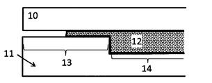
- the pinching portion is exemplified as the simplest aspect in which the pinching portion is formed to the outermost end of the substantially outer peripheral end portion of the cavity (see FIG. 3). It is preferable that the outermost portion of the substantially central part (product shape part) of the cavity is a cavity-shaped mold that leads to the pinching part with the cavity thickness gradually decreasing, and it is preferable because a molded article with ears that is more excellent in appearance can be obtained ( (See FIG. 4).
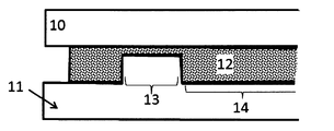
- the pinching portion is formed at a portion that is not the outermost end of the substantially outer peripheral end portion of the cavity, and as a result, the outermost cavity thickness of the substantially outer peripheral end portion of the cavity is larger than the thickness of the pinching portion. Even a cavity-shaped mold is preferable because it is easy to obtain a molded article with ears having a better appearance (see FIG. 5).
- the molded article with ears obtained by the production method of the present invention has, on the outer peripheral part, a part where the molding material is fixed at the pinching part of the mold cavity at the time of molding and an ear part corresponding to the part outside thereof. is there.
- the ear portion according to the present invention is not necessarily required in the usage of the molded body, but refers to an excess portion generated in the molded body due to the manufacturing method of the molded body as described above. Since this ear part includes a part formed by the flow of molding material, the state of orientation of reinforcing fibers has changed compared to the product shape part, and therefore the appearance and physical properties have changed compared to the product shape part. There are many.
- a fiber-reinforced resin molded article having a target product shape that does not have an ear part may be referred to as a fiber-reinforced resin processed product.
- the method for cutting the above-mentioned ears is not particularly limited, and a known method such as physical cutting such as circular saw, band saw, rutheter, end mill, or thermal cutting such as ultrasonic wave or laser should be used. Can do.
- the molded part with the ear part may be used as it is in the product for the reason that the part judged to be the ear part is unnecessary for a certain use and has a favorable effect in another use, it is included in the present invention. Is done. It is also possible to use the ear part of the molded article with the ear part for joining with other members, for example, mechanical fastening by bolts and nuts, vibration welding, or the like.
- the manufacturing method of the present invention can provide a molded article with an ear part that has a small ear part, which is difficult to obtain by the open cavity method press molding, by appropriately designing the fixing part.
- the effect of the present invention is particularly prominent when a molded article having a product shape having irregularities is obtained. This is because the pulling of the molding material at the time of the press molding is more likely to occur as the unevenness is larger, and defects such as unintended wrinkles are more likely to occur in the molded body.
- the molding material is hardly drawn.
- the molding material is likely to be drawn. This pull-in is caused by the difference between the projected area and the actual area of the cavity.
- the cavity has a planar part and a non-planar part in a cavity cross-sectional shape viewed from a direction substantially perpendicular to the clamping direction, and the surface of the planar part is continuous with the surface.
- the numerical range is deliberately limited in a direction substantially perpendicular to the approximate clamping direction, 90 ° ⁇ 45 ° with respect to the approximate clamping direction as viewed from a plane including a direction of 90 ° with respect to the approximate clamping direction.
- the range is preferably 90 ° ⁇ 30 ° with respect to the approximate clamping direction, and more preferably within the range of 90 ° ⁇ 15 ° with respect to the approximate clamping direction.
- a fiber reinforced resin material that is heated immediately before molding and is in a plastic state is placed in a mold that is adjusted to a temperature lower than the plasticization temperature of the fiber reinforced resin material, and the molded body is clamped.
- So-called cold press molding is preferable because of high productivity.
- a hot air heater, an infrared heater or the like is used as a method for heating the fiber reinforced resin material.
- Specific examples of cold press molding are as follows: After the fiber reinforced resin material is heated to a plasticizing temperature of a thermoplastic resin as a matrix + 30 ° C.
- the upper mold and the lower mold are configured in pairs, placed in a mold adjusted to a temperature equal to or lower than the softening temperature of the thermoplastic resin, clamped and pressurized, and the cooled and solidified molded body is opened. And take it out.
- the temperature at which the fiber reinforced resin material is heated to a plastic state is preferably a softening temperature + 15 ° C. or more and a decomposition temperature ⁇ 30 ° C.
- the heating temperature is within this range, it is preferable that the matrix resin is sufficiently melted and plasticized to be easily molded, and the thermoplastic resin is not decomposed so much.
- the pressurizing condition is preferably a press pressure of 0.1 MPa to 20 MPa, more preferably 0.2 MPa to 15 MPa, and further preferably 0.5 MPa to 10 MPa. Even more preferred.
- the press pressure is 0.1 MPa or more, the fiber-reinforced resin material can be sufficiently pressurized, so that it is difficult for spring back or the like to occur and the material strength is unlikely to decrease.
- the temperature in the mold during pressurization depends on the type of fiber reinforced resin material, but since the molten fiber reinforced resin material is cooled and solidified, a fiber reinforced resin molded product is formed.
- the temperature is preferably 20 ° C. or lower than the softening temperature of the thermoplastic resin which is the matrix of the material.
- the softening temperature of the resin is the crystal melting temperature, that is, the so-called melting point, for the crystalline thermoplastic resin, and the glass transition temperature for the amorphous thermoplastic resin.
- the inventors consider the mechanism of manifestation of the effect of the production method of the present invention as follows:
- the above-described closed cavity is provided by providing a portion where the applied pressure changes locally during press molding.
- the advantage of this method is that it is possible to form an unevenly-walled molded product by increasing the cavity internal pressure and flow, and molding with excellent mold transferability. It has become possible to improve changes in appearance and physical properties at the end of the product.
- the press molding it is preferable to place a molding material or a plate-like material on the upper surface of the lower mold, and then close and pressurize the upper mold to fill and mold the molding material over the entire cavity.
- the molding material disposed on the upper surface of the lower mold is pressed by the convex portion of the upper mold at the same time as the mold clamping, and the phenomenon occurs because the concave portion of the lower mold is drawn.
- this pulling phenomenon occurs in an unstable manner in the molding process. Therefore, when the amount of the molding material is partially pulled in, the portion becomes a defective portion of the molding body that is not filled with the molding material, and is pulled back.
- the molding material protrudes to the outer peripheral portion of the cavity and is sandwiched between the shear edge portions constituting the closed cavity, resulting in defective molding.
- the molding material is fixed at the cavity outer peripheral portion, thereby eliminating unfilled molding defects and occurring at the end of the product. It became possible to prevent the appearance and physical properties from being disturbed.
- thermoplastic resin As the molding material containing the reinforcing fiber used in the present invention and the thermoplastic resin as the matrix (sometimes referred to as a fiber reinforced resin material in the present invention), known materials can be preferably used.
- the abundance of the thermoplastic resin as a matrix in the fiber reinforced resin material can be appropriately determined according to the type of the thermoplastic resin, the type of the reinforced fiber, and the like, and is not particularly limited.
- the thermoplastic resin is preferably in the range of 3 to 1000 parts by weight, more preferably 30 to 200 parts by weight, still more preferably 30 to 150 parts by weight with respect to 100 parts by weight of the reinforcing fibers. .
- the amount of the thermoplastic resin as a matrix is 3 parts by weight or more with respect to 100 parts by weight of the reinforcing fibers, the resin-impregnation in the fiber-reinforced resin material is sufficient, and dry reinforcing fibers are reduced.
- the amount of the thermoplastic resin as the matrix is 1000 parts by weight or less, the amount of the reinforcing fibers is sufficient and is often suitable as a structural material.
- the term weight is sometimes used for convenience, but it is actually mass.
- the orientation state of the reinforcing fiber in the fiber reinforced resin material for example, the unidirectional orientation in which the major axis direction of the reinforcing fiber is oriented in one direction or the major axis direction is randomly oriented in the in-plane direction of the fiber reinforced resin material.
- Two-dimensional random orientation can be mentioned.
- the orientation state of the reinforcing fiber in the fiber reinforced resin material used in the present invention may be either the above-mentioned unidirectional orientation or two-dimensional random orientation. It may be an irregular orientation intermediate between the unidirectional orientation and the two-dimensional random orientation (orientation state in which the major axis direction of the reinforcing fiber is not perfectly oriented in one direction and is not completely random).
- the long axis direction of the reinforcing fiber may be oriented so as to have an angle with respect to the in-plane direction of the fiber reinforced resin material, and the reinforcing fiber is oriented so as to be entangled in cotton.
- the reinforcing fibers may be oriented such as bi-directional woven fabrics such as plain weave and twill weave, multi-axial woven fabrics, non-woven fabrics, mats, knits, braids, paper made of reinforced fibers, and the like.
- the plane orientation degree ⁇ 100 ⁇ (1- (number of reinforcing fibers having a plane orientation angle ⁇ of 10 ° or more) / (total number of reinforcing fibers))) is 90% or more.
- a certain state may be a preferable two-dimensional random orientation.
- the thickness direction of the molded body or a direction different from the thickness direction of the molded body is defined as the Z direction, and observation and measurement regarding reinforcing fibers according to the above publication
- the plane orientation degree ⁇ may be calculated.
- the reinforcing fiber mat in the present invention refers to a mat formed by accumulation or entanglement of reinforcing fibers.
- the reinforcing fiber mat include a two-dimensional random reinforcing fiber mat in which the long axis direction of the reinforcing fiber is randomly oriented in the in-plane direction of the fiber reinforced resin material, and the long axis of the reinforcing fiber by entwining the reinforcing fibers in a cotton shape.
- a three-dimensional random reinforcing fiber mat whose direction is randomly oriented in each of the XYZ directions is exemplified.
- the isotropic substrate refers to a material in which a reinforcing fiber mat contains a thermoplastic resin.
- examples of the aspect in which the reinforcing fiber mat includes the thermoplastic resin include, for example, an aspect in which the reinforcing fiber mat includes a powdery, fibrous, or massive thermoplastic resin, or the reinforcing fiber mat.
- stacked can be mentioned.
- An isotropic substrate in which the reinforcing fiber mat is a two-dimensional random reinforcing fiber mat may be particularly referred to as an in-plane isotropic substrate.
- reinforcing fibers having different orientation states may be contained in one fiber reinforced resin material.
- the reinforcing fibers having different orientation states are included in the fiber reinforced resin material, for example, (i) an aspect in which reinforcing fibers having different orientation states are arranged in the in-plane direction of the fiber reinforced resin material, (ii) fibers
- the aspect by which the reinforced fiber from which an orientation state differs in the thickness direction of a reinforced resin material can be mentioned.
- a fiber reinforced resin material has a laminated structure which consists of a several layer, the aspect from which the orientation state of the reinforced fiber contained in each layer (iii) differs can be mentioned.
- An embodiment in which the above embodiments (i) to (iii) are combined can also be exemplified.
- the orientation of reinforcing fibers in the fiber reinforced resin material is, for example, a tensile test based on an arbitrary direction of the fiber reinforced resin material and a direction orthogonal thereto, and the tensile elastic modulus is measured and then measured This can be confirmed by measuring the ratio (E ⁇ ) obtained by dividing the larger value of the elastic modulus by the smaller value. It can be evaluated that the closer the modulus ratio is to 1, the more reinforced fibers are isotropically oriented. It is considered to be in-plane isotropic when the ratio of the modulus of elasticity in the two orthogonal directions divided by the smaller one does not exceed 2, and in-plane etc.
- Basis weight of the reinforcing fibers in the fiber-reinforced resin material is not particularly limited, the lower limit value is set to 25g / m 2 ⁇ 10000g / m 2.
- the basis weight of the reinforced fibers in the fiber reinforced resin material can be obtained. It can be regarded as the basis weight of reinforcing fibers in the body.
- the thickness of the fiber reinforced resin material used in the present invention is not particularly limited, but is usually preferably in the range of 0.01 mm to 100 mm, preferably in the range of 0.01 mm to 5 mm, and in the range of 1 to 5 mm. The inside is more preferable.
- the above thickness does not indicate the thickness of each layer, but indicates the total thickness of the fiber reinforced resin obtained by summing the thickness of each layer. To do.
- the fiber reinforced resin material used in the present invention may have a single layer structure composed of a single layer, or may have a laminated structure in which a plurality of layers are laminated.
- the aspect in which the fiber reinforced resin material has the above laminated structure may be an aspect in which a plurality of layers having the same composition are laminated, or an aspect in which a plurality of layers having different compositions are laminated. Also good.
- the fiber reinforced resin material has the above-described laminated structure
- layers having different orientation states of reinforcing fibers may be laminated.
- a layer in which reinforcing fibers are unidirectionally oriented and a layer in which two-dimensional random orientation is oriented may be laminated.
- a sandwich structure including an arbitrary core layer and a skin layer laminated on the front and back surfaces of the core layer may be used.
- various fibrous or non-fibrous fillers of organic fibers or inorganic fibers, flame retardants, UV-resistant agents, stabilizers, mold release, and the like within the range not impairing the object of the present invention.
- Additives such as agents, pigments, softeners, plasticizers, surfactants and the like may be included.
- the volume ratio of the reinforcing fiber contained in the molding material (fiber reinforced resin material) used in the production method of the present invention and the molded article with ears obtained by the production method of the present invention there is no particular limitation on the volume ratio of the reinforcing fiber contained in the molding material (fiber reinforced resin material) used in the production method of the present invention and the molded article with ears obtained by the production method of the present invention.
- the reinforcing fiber and the thermoplastic resin as the matrix preferably have a reinforcing fiber volume fraction (Vf) defined by the following formula (u) of 5% to 80%. Is more preferably 20% to 60%.
- Vf 100 ⁇ reinforcing fiber volume / (reinforcing fiber volume + thermoplastic resin volume) Formula (u)
- the average value of Vf is preferably in the above range, and more preferably, both the minimum value and the maximum value of Vf are in the above range.
- Vf of the molding material can be regarded as the Vf of the molded body with ears.
- the molding material (fiber reinforced resin material) used in the present invention preferably has a tensile elongation at break ⁇ v of 105% to 400%, more preferably 105% to 260%, and more preferably 110% to 230%. And even more preferable.
- a molding material having a tensile elongation at break ⁇ v of 105% or more is preferable because it is difficult to tear even if it is bent when placed in a mold.
- a molding material having a tensile elongation at break ⁇ v of 400% or less is preferable because it hardly hangs down by its own weight when the plastic material is transported by being gripped by a robot arm.
- the tensile elongation at break ⁇ v of the molding material is the elongation of the molding material when stretched at a tensile speed of 20 mm / sec at a temperature equal to or higher than the softening temperature of the thermoplastic resin as the matrix of the molding material. It is represented by the formula (e).
- ⁇ v (%) 100 ⁇ length after stretching of molding material / length before stretching of molding material (e) More specifically, the molding material was heated to a temperature above the softening temperature of the thermoplastic resin as the matrix, the molding material over the mold for press molding of the tensile elongation at break epsilon v for measurement After placing and closing the mold at a mold clamping speed of 20 mm / sec until the molding material is broken, the molding material is taken out and the length of the molding material stretched is measured. Calculated by dividing.
- Carbon fiber is preferable as the reinforcing fiber contained in the fiber-reinforced resin molded article or fiber-reinforced resin material having the ears of the present invention, but depending on the type of matrix resin, the use of the fiber-reinforced resin material, etc.
- Any inorganic fiber or organic fiber other than the above can be used.
- inorganic fibers other than the carbon fibers include activated carbon fibers, graphite fibers, glass fibers, tungsten carbide fibers, silicon carbide fibers (silicon carbide fibers), ceramic fibers, alumina fibers, natural fibers, mineral fibers such as basalt, boron, and the like. Examples thereof include fibers, boron nitride fibers, boron carbide fibers, and metal fibers.
- Examples of the metal fiber include aluminum fiber, copper fiber, brass fiber, stainless steel fiber, and steel fiber.
- As said glass fiber what consists of E glass, C glass, S glass, D glass, T glass, quartz glass fiber, borosilicate glass fiber, etc. can be mentioned.
- Examples of the organic fibers include fibers made of resin materials such as aramid, PBO (polyparaphenylene benzoxazole), polyphenylene sulfide, polyester, acrylic, polyamide, polyolefin, polyvinyl alcohol, and polyarylate.
- the reinforcing fiber contained in the molded article with ears and the fiber reinforced resin material according to the present invention is one or more reinforcing fibers selected from the group consisting of carbon fiber, glass fiber, aramid fiber, boron fiber, basalt fiber, It is more preferable that it is in the weight average fiber length range described later.
- two or more kinds of reinforcing fibers may be used in combination.
- a plurality of types of inorganic fibers may be used in combination
- a plurality of types of organic fibers may be used in combination
- inorganic fibers and organic fibers may be used in combination.
- Examples of the mode in which a plurality of types of inorganic fibers are used in combination include a mode in which carbon fibers and metal fibers are used in combination, and a mode in which carbon fibers and glass fibers are used in combination.
- examples of the mode in which a plurality of types of organic fibers are used in combination include a mode in which aramid fibers and fibers made of other organic materials are used in combination.
- the aspect which uses together a carbon fiber and an aramid fiber can be mentioned, for example.
- carbon fibers are preferred as the reinforcing fibers. This is because carbon fiber can provide a fiber-reinforced resin material that is lightweight but has excellent strength.
- the carbon fiber generally, polyacrylonitrile (PAN) -based carbon fiber, petroleum pitch-based carbon fiber, coal pitch-based carbon fiber, rayon-based carbon fiber, cellulose-based carbon fiber, lignin-based carbon fiber, phenol-based carbon fiber, Vapor growth carbon fibers and the like are known, but any of these carbon fibers can be suitably used in the present invention.
- PAN polyacrylonitrile
- the tensile elastic modulus is preferably within a range of 100 GPa to 600 GPa, more preferably within a range of 200 GPa to 500 GPa, and within a range of 230 GPa to 450 GPa. Is more preferable. Further, the tensile strength is preferably in the range of 2000 MPa to 10,000 MPa, and more preferably in the range of 3000 MPa to 8000 MPa.
- the reinforcing fiber used in the present invention may have a sizing agent attached to the surface in order to improve the adhesion with the matrix resin.
- the type of the sizing agent can be appropriately selected according to the types of the reinforcing fiber and the matrix resin, and is not particularly limited.
- the adhesion strength between the reinforcing fiber and the matrix resin is preferably 5 MPa or more in the strand tensile shear test.
- this strength can be obtained by a method of changing the surface oxygen concentration ratio (O / C) or by applying a sizing agent to the carbon fiber so that the carbon fiber and the matrix It can be improved by a method of increasing the adhesion strength with the resin.
- the reinforcing fibers when at least a part of the reinforcing fibers has a monofilament shape, the effect becomes extremely remarkable.
- a part of the reinforcing fibers in order to increase the fluidity of the fiber reinforced resin material, it is preferable that a part of the reinforcing fibers form a bundle of single fibers.
- the reinforcing fiber may be in the form of a single fiber or a single fiber bundle, but when both are provided, the effect of the present invention can be further obtained.
- the single fiber bundle means that two or more reinforcing single fibers are close to each other by a sizing agent, electrostatic force, or the like and exist in a bundle shape.
- the number of reinforcing single fibers forming the single fiber bundle is preferably 280 or more, and more preferably 600 or more.
- the number of single fibers constituting each single-fiber bundle may be substantially uniform or different in each single-fiber bundle.
- the weight average fiber length of the reinforcing fibers contained in the molded article with ears and the fiber-reinforced resin material of the present invention is preferably 0.1 mm to 500 mm from the viewpoint of both strength and productivity.
- the weight average fiber length is more preferably 1 mm to 100 mm, still more preferably 5 mm to 100 mm, and still more preferably 10 mm to 100 mm.
- As the reinforcing fiber used in the present invention not only a discontinuous fiber having a weight average fiber length of 100 mm or less, which is excellent in in-plane isotropic strength and dimensions as described above, but a continuous fiber may be used depending on the purpose.
- reinforcing fibers having different fiber lengths may be used in combination.
- the reinforcing fiber used in the present invention may have a single peak in average fiber length, or may have a plurality of peaks.
- the average fiber length of the reinforced fibers is measured, for example, by measuring the fiber length of 100 fibers randomly extracted from the fiber reinforced resin material to the 1 mm unit using a caliper or the like, and the following formulas (m) and (f) Can be determined based on
- the method for extracting reinforcing fibers from the fiber reinforced resin material can be performed, for example, by subjecting the fiber reinforced resin material to a heat treatment of about 500 ° C. ⁇ 1 hour and removing the resin in a furnace.
- Number average fiber length Ln ⁇ Li / j (m) (Where Li is the fiber length of the reinforcing fiber and j is the number of reinforcing fibers)
- Weight average fiber length Lw ( ⁇ Li 2 ) / ( ⁇ Li) (f) (Where Li is the fiber length of the reinforcing fiber)
- the number average fiber length can be regarded as the weight average fiber length.
- the number average fiber length or the weight average fiber length may be adopted, but it is often the weight average fiber length that can more accurately reflect the physical properties of the fiber reinforced resin material.
- the single fiber diameter of the reinforcing fiber used in the present invention may be appropriately determined according to the type of the reinforcing fiber, and is not particularly limited.
- the average single fiber diameter is usually preferably in the range of 3 ⁇ m to 50 ⁇ m, more preferably in the range of 4 ⁇ m to 12 ⁇ m, and in the range of 5 ⁇ m to 8 ⁇ m. More preferably.
- the average single fiber diameter is preferably in the range of 3 to 30 ⁇ m.
- the average single fiber diameter refers to the diameter of the single fiber of the reinforcing fiber as the name suggests, but when the reinforcing fiber is a bundle of single fibers, the average single fiber diameter is the average fiber diameter. May be abbreviated.
- the average single fiber diameter of the reinforcing fiber can be measured, for example, by the method described in JIS R7607 (2000).
- the reinforcing fibers used in the present invention include a single fiber bundle, that is, two or more reinforcing single fibers that are close together and bundled by a sizing agent or electrostatic force.
- the reinforcing fiber in the form of a single fiber bundle may be referred to as a reinforcing fiber bundle for convenience.
- One reinforcing fiber bundle functions as one filler in the fiber reinforced resin molded body and its molding material.
- a bundle of multiple single fibers is obtained by randomly collecting individual reinforcing fibers with tweezers from a reinforcing fiber sample obtained by removing the matrix thermoplastic resin from a fiber reinforced resin molding or molding material.
- a typical example of the reinforcing fiber bundle is one in which a plurality of single fibers are oriented in the same direction and their longitudinal side surfaces are in contact with each other to form a bundle shape, but is not limited to this form.
- a plurality of single fibers may be bundled in various directions, and a plurality of single fibers are close to each other at a part of the longitudinal side surface, but at other parts, the single fibers are separated from each other. It may be a bundle shape.
- the reinforcing fibers used in the present invention are single fiber bundles, the number of single fibers constituting each single fiber bundle is not particularly limited, but is usually in the range of 2 to 100,000.
- carbon fibers are in the form of a single fiber bundle in which thousands to tens of thousands of single fibers are gathered.
- the reinforcing fibers if they are used in the form of a single fiber bundle, the entangled portion of the single fiber bundle may be locally thick and it may be difficult to obtain a thin fiber reinforced resin material. For this reason, when using a reinforcing fiber in the form of a single fiber bundle, the single fiber bundle is usually used after being widened or opened.
- the reinforcing fiber in the present invention is represented by the following formula (1).
- Number of critical single fibers 600 / D (1) (Where D is the average single fiber diameter ( ⁇ m) of the reinforced single fibers)
- the reinforcing fiber (A) composed of a single fiber of a number equal to or greater than the critical single fiber defined in (1) is preferably an amount such that the ratio to the total amount of reinforcing fibers is 20 vol% or more, and is an amount that is 30 vol% or more. The amount is more preferably 40 vol% or more, and particularly preferably 50 vol% or more.
- a reinforcing fiber other than the reinforcing fiber (A) there is a single fiber bundle composed of a single fiber in a single fiber state or a number of single fibers less than the critical single fiber, and may be referred to as a reinforcing fiber (B) hereinafter. May be.
- the thickness of the reinforcing fiber (A) comprised by more than the specific single fiber number is reduced, and the number of bundles of the reinforcing fiber (A) per reinforcing fiber unit weight (g). Since the thickness unevenness of the fiber reinforced resin material can be reduced by setting it to a specific range, a fiber reinforced resin molded article having excellent mechanical properties can be obtained by molding a fiber reinforced resin material containing such reinforced fibers. Is possible.
- the ratio of the amount of reinforcing fiber (A) to the total amount of carbon fiber is 20 vol% or more, it is easy to obtain a good molded article having a high reinforcing fiber volume content when the fiber-reinforced resin material of the present invention is molded. It is preferable. On the other hand, it is preferable that the upper limit of the ratio of the amount of the reinforcing fiber (A) is 99 vol%. If the ratio of the amount of reinforcing fiber (A) to the total amount of fibers is 99 vol% or less, the fiber gap is not increased, and a composite material having excellent mechanical strength can be obtained.
- the ratio of the amount of reinforcing fiber (A) to the total amount of reinforcing fibers is more preferably 50 vol% or more and less than 99 vol%, and still more preferably 60 vol% or more and 90 vol% or less. That is, the upper limit of the ratio of the amount of reinforcing fiber (A) to the total amount of reinforcing fibers is more preferably 95 vol% or less, and still more preferably 90 vol% or less.
- the reinforcing fiber (A) is a bundle of reinforcing single fibers, it may be referred to as a reinforcing fiber bundle (A) for convenience.
- the average number of single fibers of the reinforcing fiber (A) may be abbreviated as the average number of fibers.
- thermoplastic resin In the molded article with ears and the fiber reinforced resin material according to the present invention, a thermoplastic resin is included as a matrix resin.
- a thermoplastic resin As the matrix resin, a thermosetting resin may be used in combination as long as the main component is a thermoplastic resin.
- the thermoplastic resin is not particularly limited, and a resin having a desired softening temperature can be appropriately selected and used depending on the use of the molded article with ears or the processed product thereof.
- the thermoplastic resin those having a softening temperature in the range of 180 ° C. to 350 ° C. are preferably used, but are not limited thereto.
- the softening temperature of the thermoplastic resin is the crystal melting temperature, so-called melting point, for the crystalline thermoplastic resin, and the glass transition temperature for the amorphous thermoplastic resin.
- thermoplastic resin examples include polyolefin resin, polystyrene resin, thermoplastic polyamide resin, polyester resin, polyacetal resin (polyoxymethylene resin), polycarbonate resin, (meth) acrylic resin, polyarylate resin, polyphenylene ether resin, polyimide resin, One or more kinds selected from the group consisting of polyether nitrile resin, phenoxy resin, polyphenylene sulfide resin, polysulfone resin, polyketone resin, polyether ketone resin, thermoplastic urethane resin, fluorine resin, thermoplastic polybenzimidazole resin, etc. Can be mentioned.
- polystyrene resin examples include one or more selected from the group consisting of polyethylene resin, polypropylene resin, polybutadiene resin, polymethylpentene resin, vinyl chloride resin, vinylidene chloride resin, vinyl acetate resin, polyvinyl alcohol resin, and the like.
- polystyrene resin examples include one or more selected from the group consisting of polystyrene resin, acrylonitrile-styrene resin (AS resin), acrylonitrile-butadiene-styrene resin (ABS resin), and the like.
- polyamide resin examples include polyamide 6 resin (nylon 6), polyamide 11 resin (nylon 11), polyamide 12 resin (nylon 12), polyamide 46 resin (nylon 46), polyamide 66 resin (nylon 66), and polyamide 610.
- polyamide 610 polyamide 6 resin
- polyamide 11 resin polyamide 11
- polyamide 12 resin polyamide 12
- polyamide 46 resin polyamide 46
- polyamide 66 resin polyamide 610
- polyamide 610 polyamide 610.
- polyester resin examples include polyethylene terephthalate resin, polyethylene naphthalate resin, boribylene terephthalate resin, polytrimethylene terephthalate resin, and liquid crystal polyester.
- Examples of the (meth) acrylic resin include polymethyl methacrylate.
- Examples of the modified polyphenylene ether resin include modified polyphenylene ether.
- Examples of the thermoplastic polyimide resin include thermoplastic polyimide, polyamideimide resin, polyetherimide resin, and the like.
- Examples of the polysulfone resin include one or more types selected from the group consisting of a modified polysulfone resin, a polyethersulfone resin, and the like.
- Examples of the polyether ketone resin include one or more selected from the group consisting of a polyether ketone resin, a polyether ether ketone resin, and a polyether ketone ketone resin.
- fluororesin, polytetrafluoroethylene etc. can be mentioned, for example.
- thermoplastic resin used in the present invention may be only one type or two or more types.
- modes in which two or more types of thermoplastic resins are used in combination include modes in which thermoplastic resins having different softening temperatures are used in combination and modes in which thermoplastic resins having different average molecular weights are used in combination. But this is not the case.
- the fiber reinforced resin material used in the present invention can be produced using a known method.
- a thermoplastic resin for example: 1. a step of cutting the reinforcing fiber; 2. opening the cut reinforcing fiber; It is possible to manufacture the fiber-reinforced resin material by mixing the opened reinforcing fiber and the fibrous or particulate matrix resin to obtain an isotropic base material, and then heating and compressing it to promote impregnation with the thermoplastic resin. Yes, but not necessarily.
- An isotropic substrate also called a two-dimensional random orientation mat
- a method for producing the same are described in detail in the specification of WO2012 / 105080 pamphlet and JP2013-49298A.
- a strand composed of a plurality of reinforcing fibers is continuously slit along the reinforcing fiber length direction as necessary to form a plurality of narrow strands having a width of 0.05 mm to 5 mm, and then an average fiber length of 3 mm to 100 mm.
- a mat is obtained by continuously cutting and depositing in layers on a breathable conveyor net etc. in a state where gas is blown to the cut reinforcing fibers to open them into reinforcing fibers having a smaller number of single fibers. be able to.
- thermoplastic resin in the form of granules or short fibers is deposited on the breathable conveyor net together with the reinforcing fibers, or the molten thermoplastic resin is supplied to the mat-like reinforcing fiber layer as a film and penetrated. It can also be produced by a method of producing an isotropic substrate including a thermoplastic resin.
- the size of the reinforcing fibers to be subjected to the cutting step in the above-described preferred method for producing an isotropic substrate for example, the width and width of the reinforcing fibers as a single fiber bundle It can be controlled by adjusting the number of single fibers per unit. Specifically, a method of expanding the width of the reinforcing fiber by expanding the width and using it for the cutting step, or a method of providing a slit step before the cutting step can be mentioned. Further, the reinforcing fiber may be slit simultaneously with the cutting.
- the reinforcing fibers are not oriented in a specific direction and are dispersed in a random direction in the plane. That is, such a fiber reinforced resin material is an in-plane isotropic material.
- the in-plane isotropy of the fiber reinforced resin material can be quantitatively evaluated.
- the external appearance of the flange part (it may be abbreviated as an end part in this example) and the vertical surface of the fiber reinforced resin molded article was visually observed and evaluated based on the following criteria.
- C (slightly good): The transfer on the mold surface is partially insufficient, and the surface has a mottled pattern, and the part where the surface gloss is lost and the part where the gloss is glossy can be clearly recognized.
- Full shot stability is a measure of whether a good molded article can be obtained even if press molding is continuously performed, that is, a molded article can be stably produced. As an evaluation of full shot stability, 20 shots were continuously formed, and when 20 full shot compacts were obtained, “good” was indicated when unfilled compacts were included.
- a hemispherical recess having a radius of 300 ⁇ m is provided on the surface of the mold, corresponding to the flange portion at the end of the target molded body, and the height of the hemisphere of the obtained molded body is determined. It was measured and evaluated by how close the height was to 300 ⁇ m.
- FIGS. 5 The position of the cavity pressure measured by the pressure sensor is shown in the schematic views of the molded body in FIGS. More precisely, a pressure sensor was installed at the position of the mold cavity surface corresponding to the position, and the cavity internal pressure was measured. Since this pressure sensor measures the pressure applied to the mold cavity surface, it becomes difficult to accurately measure the pressure applied to the molding material as the molding material in the cavity cools and solidifies. Therefore, in the embodiment of the present invention, the pressure for 3 seconds from the start of pressurization was measured, and the highest pressure was recorded during that time to obtain the pressure value.
- the thickness value of the obtained molded body is a value obtained by measuring the thickness at the position shown in the schematic view of the molded body in FIGS. 1 and 2 with a micrometer.
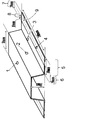
- Mold and mold shape As shown in FIG. 1 and FIG. 2, a mold composed of an upper mold and a lower mold is formed in which a cavity corresponding to a molded body having a hat-shaped cross section of 30 mm in height and 10 mm in thickness and 2.5 mm in thickness is formed. It was used for press molding.
- the width of the portion corresponding to the flange portion of the molded body is 40 mm, of which the portion having a width of 20 mm is a region having a thickness of 2.5 mm that is interpreted as a part of the substantially central portion of the cavity.
- the remaining width of 20 mm is a region including the pinching part of the cavity.
- the portion where the pinching portion is formed is a block having a nested structure, and the thickness and width of the pinching portion can be adjusted by exchanging the block.
- the longitudinal direction of the molded body obtained by molding using the mold is defined as the Y-axis direction of the XYZ coordinate system, and the height is defined as the Z-axis direction.
- the size of the molded body in the X-axis direction in this case is the width.
- a mold having a cavity shape corresponding to a 400 mm ⁇ 400 mm flat plate-shaped molded body (hereinafter sometimes referred to as a flat plate-shaped mold) was used.
- molding machine In this application, a hydraulic 5000 kN press machine manufactured by Kawasaki Oil Works Co., Ltd. was used. Unless otherwise specified, the molding conditions are the same. Specifically, a molding die, which will be described later, is attached, the pressing pressure is 15 MPa, the molding die temperature is 150 ° C., and the molding material heating temperature is 290 ° C. Molding was performed.
- a PAN-based carbon fiber “TENAX” registered trademark
- STS40-24KS average single fiber diameter: 7 ⁇ m, number of single fibers: 24,000
- An in-plane isotropic base material in which the fibers are two-dimensionally randomly oriented and has a carbon fiber basis weight of 1800 g / m 2 was prepared.
- the obtained in-plane isotropic base material was put into a flat plate mold set at 250 ° C., pressurized at 2 MPa for 10 minutes, the mold temperature was lowered to 100 ° C., and the carbon fibers were two-dimensionally randomly oriented.
- the molding material has a reinforcing fiber volume fraction (Vf) of 35%, the weight average fiber length of the reinforcing fibers contained is 20 mm, the number of critical single fibers is 86, and the total number of reinforcing fibers is not less than the number of critical single fibers.
- the ratio of the amount of the reinforcing fiber (A) composed of the carbon single fibers of the number was 77 vol%.
- bundles composed of carbon single fibers having a number less than the number of critical single fibers and single carbon fibers were also present.
- This molding material has a tensile elongation at break ⁇ v determined by the above formula (e) in the range of 105% to 400%.
- Example 1 Using the 2.6 mm thick molding material obtained in Production Example 1 cut into a 700 mm ⁇ 190 mm rectangular mold, press molding (20 shot continuous molding) was performed according to the following procedure.
- a mold having a cavity having a shape corresponding to a hat-shaped molded body having a height of 30 mm (FIG. 1) was used as the mold.
- the block of the pinching portion of this mold was set so that the gap (pinching portion) thickness was 1.5 mm and the width of the pinching portion was 10 mm from the end of the substantially central portion of the cavity.
- Clamping of the mold was started by placing the heated molding material in a plastic state on the lower mold of the mold so that both ends in the width direction are sandwiched between the pinching sections of the mold cavity. .
- the periphery of the central part of the molding material (substantially central part) is drawn into the space around the convex part of the lower mold by the concave part of the upper mold, and then both ends of the molding material are pushed by the pinching part of the cavity by clamping.
- the molds were fixed while being crushed and the mold clamping was further advanced, the both ends of the molding material were fixed at the pinching part without shifting, and the molding material became a hat shape according to the cavity shape.
- hat-shaped fiber-reinforced resin molded body having an ear portion width may be abbreviated as a hat-shaped molded body hereinafter
- ear portion width 10 mm
- the ear part of the hat-shaped molded body became a part having a width of 20 mm from both ends in the width direction.
- the maximum pressure cavity projected area of the mold 945 cm 2 the area of the pinching unit which acts on pinching unit in 140cm 2
- clamping is acting 38 MPa
- the maximum pressure was 20 MPa.
- the clamping force was set to 1890 kN and a pressure of 20 MPa per cavity projected area.
- the pinching constant Kp MPa ⁇ cm 2 / kN defined by the above formula (p) is 0.28. there were.
- the ear part of the hat-shaped molded body having the ear part obtained as described above was cut with an end mill to obtain a fiber-reinforced resin processed product.
- the appearance of the end portion was good without any flow marks or transfer defects.
- the height of the hemispherical projection with a design radius of 300 ⁇ m installed on the product flange was 280 ⁇ m, and the surface transferability was also good.
- the thickness of the top surface of the hat-shaped molded body is 2.4 mm, and the thickness of the vertical surface is 2.4 mm, which is a uniform thickness according to the cavity. The appearance was good.
- Table 1 shows the evaluation results regarding the molding of this example.
- Example 2 The operation was performed in the same manner as in Example 1 except that the block of the molding die was changed and the pinching part thickness was set to 1.3 mm, the pinching part width was set to 5 mm, and the pinching part area was 70 cm 2 . Similar to Example 1, a hat-shaped molded article having a good appearance could be obtained continuously.
- the maximum pressure of the pinching part was 56 MPa, the maximum cavity pressure was 20 MPa, and the pinching constant Kp (MPa ⁇ cm 2 / kN) was 0.20. Table 1 shows the evaluation results regarding the molding of this example.
- Example 3 The operation was performed in the same manner as in Example 1 except that the block of the mold was changed and the pinching portion thickness was set to 1.0 mm, the pinching portion width was set to 3 mm, and the pinching portion area was 42 cm 2 . Similar to Example 1, a hat-shaped molded article having a good appearance could be obtained continuously.
- the maximum pressure at the pinching part was 73 MPa, the maximum cavity pressure was 20 MPa, and the pinching constant Kp (MPa ⁇ cm 2 / kN) was 0.16. Table 1 shows the evaluation results regarding the molding of this example.
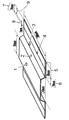
- Example 4 As a mold, a mold having a cavity for a hat-shaped molded body having a height of 10 mm described in FIG. 2 instead of FIG. 1 is used.
- the pin of the pinch part of the mold has a thickness of 1.3 mm and a pinch part.
- the width was set to 2 mm, and the same operation as in Example 1 was performed except that the molding material was cut into a rectangular shape of 700 mm ⁇ 150 mm. Similar to Example 1, a hat-shaped molded article having a good appearance could be obtained continuously.
- the cavity projected area 945 cm 2 the area of the pinching unit is 28cm 2
- the maximum pressure acting on the pinching part 49 MPa the maximum pressure of the cavity was 20 MPa.
- the clamping force was set to 1890 kN and a pressure of 20 MPa per cavity projected area.
- the pinching constant Kp (MPa ⁇ cm 2 / kN) was 0.08. Table 1 shows the evaluation results regarding the molding of this example.
- Example 5 The operation was performed in the same manner as in Example 1 except that a molding material having a reinforcing fiber (A) amount of 87 vol% in the total amount of reinforcing fibers was used. Similar to Example 1, a hat-shaped molded article having a good appearance could be obtained continuously. The maximum pressure in the pinching part was 32 MPa, and the pinching constant Kp (MPa ⁇ cm 2 / kN) was 0.23. Table 1 shows the evaluation results regarding the molding of this example.
- Example 6 The operation was performed in the same manner as in Example 1 except that a molding material having a reinforcing fiber (A) amount of 65 vol% in the total amount of reinforcing fibers was used. Similar to Example 1, a hat-shaped molded article having a good appearance could be obtained continuously. The maximum pressure in the pinching part was 38 MPa, and the pinching constant Kp (MPa ⁇ cm 2 / kN) was 0.28. Table 2 shows the results of evaluation regarding the molding of this example.
- the molding die is not the one shown in FIG. 1 but has a cavity shape corresponding to a 400 mm ⁇ 400 mm ⁇ 2.5 mm flat plate shaped body, and a 20 mm wide region on the entire outer periphery of the cavity is a substantially outer peripheral end.
- the product shape part substantially central part
- the operation was performed in the same manner as in Example 1 except that a pinch part having a thickness of 1.5 mm and a pinching width of 5 mm was used. Also in this example, it was possible to continuously obtain a molded article having a good appearance and having ears.
- the cavity area is 1600 cm 2
- the pinching area is 77 cm 2
- the maximum pressure in the pinching area is 38 MPa
- the maximum cavity pressure is 20 MPa
- the pinching constant Kp MPa ⁇ cm 2 / kN
- Example 8 The operation was performed in the same manner as in Example 1 except that a molding material having a reinforcing fiber (A) amount of 95 vol% in the total amount of reinforcing fibers was used.
- a hat-shaped molded article having a good appearance could be continuously obtained in the same manner as in Example 1, but the amount of molding material flowing out from the pinching part was slightly increased during press molding, and the obtained ear part was obtained.
- the thickness of the top surface decreased and a difference in thickness occurred between the top surface portion and the elevation surface portion. Furthermore, the surface transferability of the flange portion was lowered.
- the maximum pressure in the pinching part was 33 MPa, and the pinching constant Kp (MPa ⁇ cm 2 / kN) was 0.24. Table 2 shows the results of evaluation regarding the molding of this example.
- Example 9 The operation was performed in the same manner as in Example 1 except that the molding material having a reinforcing fiber (A) ratio of 55 vol% in the total amount of reinforcing fibers was used. Although a hat-shaped molded article having a good appearance could be continuously obtained in the same manner as in Example 1, the thickness of the top surface of the hat-shaped molded article having the obtained ears increased, and the vertical surface The thickness of the portion was reduced, and the appearance of the elevation portion was slightly deteriorated. Furthermore, the surface transferability of the flange portion was considerably lowered. The maximum pressure in the pinching part was 41 MPa, and the pinching constant Kp (MPa ⁇ cm 2 / kN) was 0.31. Table 2 shows the results of evaluation regarding the molding of this example.
- Example 10 The operation was performed in the same manner as in Example 1 except that the block of the mold was changed and the pinching part thickness was set to 0.5 mm, the pinching part width was set to 5 mm, and the pinching part area was 70 cm 2 . A hat-shaped molded article having a slightly good appearance could be continuously obtained.
- the maximum pressure at the pinching part was 110 MPa, the maximum cavity pressure was 12 MPa, and the pinching constant Kp (MPa ⁇ cm 2 / kN) was 0.41.
- Table 2 shows the results of evaluation regarding the molding of this example.
- Example 1 Except for press molding by the method of installing needle-shaped projections at a pitch of 100 mm on the block of the lower mold pinching part, starting the mold clamping after fixing the molding material heated and plasticized with a needle The same operation as in Example 1 was performed.
- the hat-shaped molded body having the obtained ear part has an extremely thin wall on the top surface, the wrinkle mark on the vertical surface part does not disappear and the appearance is poor, and the transferability of the flange part is also extremely It was lowered and it was hard to say that it was a good product. This is presumably because, in press molding, the molding material was fixed before the start of clamping, the molding material was not pulled in by clamping, and the molding material was significantly stretched by clamping. Table 3 shows the results of evaluation regarding molding of this comparative example.
- Example 2 As a molding die, a molding die in which a block of a part forming the lower mold pinching portion is flat, and a pressing block which is a working nesting that makes a stroke of 40 mm by clamping is installed in a part forming the upper mold pinching portion.
- the same operation as in Example 1 was performed except that the molding material was fixed at a position higher by 40 mm before the molding material was sandwiched between the upper die and the lower die by clamping. .
- the hat-shaped molded body having the obtained ear part has an extremely thin top surface part, the wrinkle marks on the vertical part do not disappear, and the appearance is poor, and the transferability of the flange part is extremely poor. It was something that was hard to say. This is presumably because, in press molding, the molding material was fixed before the start of clamping, the molding material was not pulled in by clamping, and the molding material was significantly stretched by clamping. Table 3 shows the results of evaluation regarding molding of this comparative example.
- Example 3 The same operation as in Example 1 was performed except that the molding material was cut into a rectangular shape of 700 mm ⁇ 140 mm. In continuous press molding, short shots occurred, and it was difficult to say that a molded body could be stably produced. The obtained hat-shaped molded body having the ear portion had a poor appearance in which a flow mark was generated at the end portion. This is because in press molding, the molding material was pushed by the upper mold and pulled into the recess of the lower mold almost simultaneously with the start of mold clamping, and the mold clamping was performed without fixing the end of the molding material at the pinching part. I think that the. Table 3 shows the results of evaluation regarding molding of this comparative example.
- the pinching part thickness was set to 2.5 mm, which is the same as the thickness at the substantial cavity (the thickness of the substantially central part of the cavity), and the molding material began to be drawn into the space around the convex part of the lower mold.
- the operation was performed in the same manner as in Example 1 except that both end portions of the molding material were not fixed by the pinching portion.
- the molding material can be stably produced due to the instability of drawing the molding material into the molding die at the start of mold clamping and the occurrence of short shots.
- the obtained hat-shaped molded body having the ear portion had extremely poor transferability at the flange portion. Table 3 shows the results of evaluation regarding molding of this comparative example.
- the production method of the present invention makes it possible to produce a fiber-reinforced resin molded article excellent in appearance with high mass productivity, and requires excellent physical properties such as structural parts such as automobiles and high cost competitiveness. Suitable for use.
Abstract
Priority Applications (3)
| Application Number | Priority Date | Filing Date | Title |
|---|---|---|---|
| EP17736002.1A EP3401072B1 (fr) | 2016-01-08 | 2017-01-06 | Procédé de fabrication d'un moulage en résine avec renfort de fibres |
| JP2017560419A JP6883527B2 (ja) | 2016-01-08 | 2017-01-06 | 繊維強化樹脂成形体の製造方法 |
| US16/068,538 US10889076B2 (en) | 2016-01-08 | 2017-01-06 | Method for producing fiber-reinforced resin shaped product |
Applications Claiming Priority (2)
| Application Number | Priority Date | Filing Date | Title |
|---|---|---|---|
| JP2016003024 | 2016-01-08 | ||
| JP2016-003024 | 2016-01-08 |
Publications (1)
| Publication Number | Publication Date |
|---|---|
| WO2017119465A1 true WO2017119465A1 (fr) | 2017-07-13 |
Family
ID=59274127
Family Applications (1)
| Application Number | Title | Priority Date | Filing Date |
|---|---|---|---|
| PCT/JP2017/000198 WO2017119465A1 (fr) | 2016-01-08 | 2017-01-06 | Procédé de fabrication d'un moulage en résine avec renfort de fibres |
Country Status (4)
| Country | Link |
|---|---|
| US (1) | US10889076B2 (fr) |
| EP (1) | EP3401072B1 (fr) |
| JP (1) | JP6883527B2 (fr) |
| WO (1) | WO2017119465A1 (fr) |
Cited By (4)
| Publication number | Priority date | Publication date | Assignee | Title |
|---|---|---|---|---|
| CN107791428A (zh) * | 2017-11-20 | 2018-03-13 | 常州市新创智能科技有限公司 | 一种帽型长桁生产设备及其生产方法 |
| JP2021003867A (ja) * | 2019-06-27 | 2021-01-14 | 株式会社The MOT Company | 繊維強化複合材料成形品のプレス成形装置及びプレス成形方法。 |
| EP3778174A4 (fr) * | 2018-03-30 | 2021-12-15 | Toray Industries, Inc. | Procédé pour la fabrication d'un article moulé |
| US20220009179A1 (en) * | 2019-03-28 | 2022-01-13 | Teijin Limited | Method for producing press-molded body |
Families Citing this family (4)
| Publication number | Priority date | Publication date | Assignee | Title |
|---|---|---|---|---|
| CN113226690A (zh) * | 2018-12-25 | 2021-08-06 | 帝人株式会社 | 纤维增强热塑性树脂成型体及其制造方法 |
| US11511502B2 (en) * | 2019-08-27 | 2022-11-29 | Spirit Aerosystems, Inc. | Method for securing core to tool during machining |
| CN111136847A (zh) * | 2020-01-14 | 2020-05-12 | 安徽理工大学 | 一种自动化塑胶盖帽的边沿膨胀装置及其控制方法 |
| CN117863267B (zh) * | 2024-03-11 | 2024-05-07 | 四川腾创汇鑫新材料科技有限公司 | 一种玄武岩纤维复合板局部热切割一体化装置及方法 |
Citations (6)
| Publication number | Priority date | Publication date | Assignee | Title |
|---|---|---|---|---|
| JPH06335934A (ja) * | 1993-05-28 | 1994-12-06 | Mitsubishi Petrochem Co Ltd | フランジ部を有する衝撃吸収部材及びその成形方法 |
| JP2009196145A (ja) * | 2008-02-20 | 2009-09-03 | Toray Ind Inc | プレス成形方法および成形体 |
| JP2011075121A (ja) * | 2009-09-29 | 2011-04-14 | Inoac Corp | ダクト及びその製造方法 |
| JP2013173334A (ja) * | 2012-02-27 | 2013-09-05 | Ibaraki Kogyo Kk | 立体添加物付き繊維強化プラスチック成形体の成形方法 |
| JP2014094489A (ja) * | 2012-11-08 | 2014-05-22 | Kita Tekkojo Kk | プレス成形装置、及び、プレス成形方法 |
| WO2015194533A1 (fr) * | 2014-06-20 | 2015-12-23 | 帝人株式会社 | Procédé de fabrication de corps moulé possédant une partie ouverture, et corps moulé |
Family Cites Families (9)
| Publication number | Priority date | Publication date | Assignee | Title |
|---|---|---|---|---|
| CA2179820C (fr) * | 1994-12-02 | 2006-10-24 | Rainer F. Gardill | Panneau moule a parement decoratif fait a partir de fibres naturels et plastiques et procede de fabrication |
| US5614285A (en) | 1994-12-02 | 1997-03-25 | Ceats | Molded panel having a decorative facing and made from a blend of natural and plastic fibers |
| FR2806349B1 (fr) * | 2000-03-20 | 2002-12-06 | Plastic Omnium Cie | Procede de fabrication d'une piece en matiere plastique renforcee |
| JP4491041B1 (ja) | 2009-05-11 | 2010-06-30 | 日本省力機械株式会社 | 樹脂製品製造システム及び製造方法 |
| JP5691699B2 (ja) | 2010-03-24 | 2015-04-01 | 東レ株式会社 | プレス成形方法およびその成形体 |
| JP5855401B2 (ja) | 2011-09-21 | 2016-02-09 | 三菱レイヨン株式会社 | 繊維強化熱可塑性樹脂成形品の製造方法 |
| DE102012217373A1 (de) * | 2012-09-26 | 2014-05-28 | Bayerische Motoren Werke Aktiengesellschaft | Verfahren und Vorrichtung zum Erzeugen von Faserverbundbauteilen |
| JP2015085537A (ja) | 2013-10-28 | 2015-05-07 | トヨタ自動車株式会社 | 熱可塑性樹脂材料の成形方法 |
| DE102013222357B4 (de) * | 2013-11-04 | 2023-03-23 | Bayerische Motoren Werke Aktiengesellschaft | Formwerkzeug und Verfahren zum Bearbeiten eines Faserverbundbauteils |
-
2017
- 2017-01-06 JP JP2017560419A patent/JP6883527B2/ja active Active
- 2017-01-06 US US16/068,538 patent/US10889076B2/en active Active
- 2017-01-06 WO PCT/JP2017/000198 patent/WO2017119465A1/fr active Application Filing
- 2017-01-06 EP EP17736002.1A patent/EP3401072B1/fr active Active
Patent Citations (6)
| Publication number | Priority date | Publication date | Assignee | Title |
|---|---|---|---|---|
| JPH06335934A (ja) * | 1993-05-28 | 1994-12-06 | Mitsubishi Petrochem Co Ltd | フランジ部を有する衝撃吸収部材及びその成形方法 |
| JP2009196145A (ja) * | 2008-02-20 | 2009-09-03 | Toray Ind Inc | プレス成形方法および成形体 |
| JP2011075121A (ja) * | 2009-09-29 | 2011-04-14 | Inoac Corp | ダクト及びその製造方法 |
| JP2013173334A (ja) * | 2012-02-27 | 2013-09-05 | Ibaraki Kogyo Kk | 立体添加物付き繊維強化プラスチック成形体の成形方法 |
| JP2014094489A (ja) * | 2012-11-08 | 2014-05-22 | Kita Tekkojo Kk | プレス成形装置、及び、プレス成形方法 |
| WO2015194533A1 (fr) * | 2014-06-20 | 2015-12-23 | 帝人株式会社 | Procédé de fabrication de corps moulé possédant une partie ouverture, et corps moulé |
Cited By (4)
| Publication number | Priority date | Publication date | Assignee | Title |
|---|---|---|---|---|
| CN107791428A (zh) * | 2017-11-20 | 2018-03-13 | 常州市新创智能科技有限公司 | 一种帽型长桁生产设备及其生产方法 |
| EP3778174A4 (fr) * | 2018-03-30 | 2021-12-15 | Toray Industries, Inc. | Procédé pour la fabrication d'un article moulé |
| US20220009179A1 (en) * | 2019-03-28 | 2022-01-13 | Teijin Limited | Method for producing press-molded body |
| JP2021003867A (ja) * | 2019-06-27 | 2021-01-14 | 株式会社The MOT Company | 繊維強化複合材料成形品のプレス成形装置及びプレス成形方法。 |
Also Published As
| Publication number | Publication date |
|---|---|
| US10889076B2 (en) | 2021-01-12 |
| EP3401072A1 (fr) | 2018-11-14 |
| EP3401072A4 (fr) | 2018-12-26 |
| JP6883527B2 (ja) | 2021-06-09 |
| JPWO2017119465A1 (ja) | 2018-10-25 |
| US20190016067A1 (en) | 2019-01-17 |
| EP3401072B1 (fr) | 2020-04-29 |
Similar Documents
| Publication | Publication Date | Title |
|---|---|---|
| WO2017119465A1 (fr) | Procédé de fabrication d'un moulage en résine avec renfort de fibres | |
| JP6782582B2 (ja) | 繊維強化複合材料成形体およびその製造方法 | |
| JP5952510B2 (ja) | 開口部を有する成形体の製造方法 | |
| JP6807880B2 (ja) | 不連続強化繊維と、マトリックスとしての熱可塑性樹脂とを含むプレス成形材料、その成形体、およびそれらの製造方法 | |
| EP3492233B1 (fr) | Procédé de production par moulage à la presse | |
| JP6574491B2 (ja) | プレス成形体の製造方法 | |
| JP5749343B2 (ja) | アンダーカット部を有する複合成形体の製造方法 | |
| JP6643126B2 (ja) | プレス成形体の製造方法、及びプレス成形体の製造装置 | |
| US10086540B2 (en) | Method for manufacturing press molded product and manufacturing apparatus for press molded product | |
| JP5598931B2 (ja) | 繊維強化された樹脂基材、樹脂成形体の製造方法及びその実施のための樹脂加工機 | |
| JP6496829B2 (ja) | 孔を有する成形体、及びその製造方法 | |
| JP2017024392A (ja) | 引止部を有する成形体、および成形体の製造方法 | |
| JP6814163B2 (ja) | 表面の少なくとも一部にシボを有する繊維強化樹脂成形体 | |
| JP7147046B2 (ja) | プレス成形体の製造方法 | |
| JP2023101237A (ja) | 繊維強化樹脂接合体 | |
| Wakeman et al. | Robotic tow placement for local reinforcement of glass mat thermoplastics |
Legal Events
| Date | Code | Title | Description |
|---|---|---|---|
| 121 | Ep: the epo has been informed by wipo that ep was designated in this application |
Ref document number: 17736002 Country of ref document: EP Kind code of ref document: A1 |
|
| ENP | Entry into the national phase |
Ref document number: 2017560419 Country of ref document: JP Kind code of ref document: A |
|
| NENP | Non-entry into the national phase |
Ref country code: DE |
|
| WWE | Wipo information: entry into national phase |
Ref document number: 2017736002 Country of ref document: EP |
|
| ENP | Entry into the national phase |
Ref document number: 2017736002 Country of ref document: EP Effective date: 20180808 |