WO2017115806A1 - 靴 - Google Patents
靴 Download PDFInfo
- Publication number
- WO2017115806A1 WO2017115806A1 PCT/JP2016/088937 JP2016088937W WO2017115806A1 WO 2017115806 A1 WO2017115806 A1 WO 2017115806A1 JP 2016088937 W JP2016088937 W JP 2016088937W WO 2017115806 A1 WO2017115806 A1 WO 2017115806A1
- Authority
- WO
- WIPO (PCT)
- Prior art keywords
- shoe
- fiber sheet
- upper material
- yarns
- yarn
- Prior art date
Links
Images


Classifications
-
- D—TEXTILES; PAPER
- D03—WEAVING
- D03D—WOVEN FABRICS; METHODS OF WEAVING; LOOMS
- D03D15/00—Woven fabrics characterised by the material, structure or properties of the fibres, filaments, yarns, threads or other warp or weft elements used
- D03D15/50—Woven fabrics characterised by the material, structure or properties of the fibres, filaments, yarns, threads or other warp or weft elements used characterised by the properties of the yarns or threads
- D03D15/567—Shapes or effects upon shrinkage
-
- D—TEXTILES; PAPER
- D03—WEAVING
- D03D—WOVEN FABRICS; METHODS OF WEAVING; LOOMS
- D03D15/00—Woven fabrics characterised by the material, structure or properties of the fibres, filaments, yarns, threads or other warp or weft elements used
- D03D15/50—Woven fabrics characterised by the material, structure or properties of the fibres, filaments, yarns, threads or other warp or weft elements used characterised by the properties of the yarns or threads
- D03D15/587—Woven fabrics characterised by the material, structure or properties of the fibres, filaments, yarns, threads or other warp or weft elements used characterised by the properties of the yarns or threads adhesive; fusible
-
- A—HUMAN NECESSITIES
- A43—FOOTWEAR
- A43B—CHARACTERISTIC FEATURES OF FOOTWEAR; PARTS OF FOOTWEAR
- A43B23/00—Uppers; Boot legs; Stiffeners; Other single parts of footwear
- A43B23/02—Uppers; Boot legs
-
- D—TEXTILES; PAPER
- D03—WEAVING
- D03D—WOVEN FABRICS; METHODS OF WEAVING; LOOMS
- D03D1/00—Woven fabrics designed to make specified articles
-
- D—TEXTILES; PAPER
- D03—WEAVING
- D03D—WOVEN FABRICS; METHODS OF WEAVING; LOOMS
- D03D15/00—Woven fabrics characterised by the material, structure or properties of the fibres, filaments, yarns, threads or other warp or weft elements used
- D03D15/20—Woven fabrics characterised by the material, structure or properties of the fibres, filaments, yarns, threads or other warp or weft elements used characterised by the material of the fibres or filaments constituting the yarns or threads
- D03D15/283—Woven fabrics characterised by the material, structure or properties of the fibres, filaments, yarns, threads or other warp or weft elements used characterised by the material of the fibres or filaments constituting the yarns or threads synthetic polymer-based, e.g. polyamide or polyester fibres
-
- D—TEXTILES; PAPER
- D03—WEAVING
- D03D—WOVEN FABRICS; METHODS OF WEAVING; LOOMS
- D03D15/00—Woven fabrics characterised by the material, structure or properties of the fibres, filaments, yarns, threads or other warp or weft elements used
- D03D15/50—Woven fabrics characterised by the material, structure or properties of the fibres, filaments, yarns, threads or other warp or weft elements used characterised by the properties of the yarns or threads
- D03D15/56—Woven fabrics characterised by the material, structure or properties of the fibres, filaments, yarns, threads or other warp or weft elements used characterised by the properties of the yarns or threads elastic
Definitions
- the present invention relates to a shoe, and more particularly to a shoe in which a part or all of an upper material is formed of a fiber sheet.
- a shoe having an upper material made of a fiber sheet is superior in light weight as compared with leather shoes.
- this type of shoe is usually comfortable for the user even when the upper material is easily deformed in accordance with the force applied to the foot and is used in sports.
- a flat fiber sheet is cut into a predetermined shape, and after the fiber sheet is sewn and an upper material having a three-dimensional shape is produced, the upper material and the sole member And are made by bonding.
- the shape of the human foot is a complex curved surface, it is not easy to sufficiently fit the upper material to the user's foot. That is, the conventional shoe has a problem that it is not easy to manufacture it into a desired shape. And no sufficient solution has been found for such problems.
- An object of the present invention is to solve such problems, and an object of the present invention is to provide a shoe that can be easily manufactured to have a desired shape.
- the present invention provides a shoe in which a part or all of the upper material is formed of a fiber sheet, the fiber sheet having heat shrinkability and a direction along a shoe center axis.
- a shoe that exhibits higher heat shrinkage in the direction perpendicular to the shoe center axis is provided.
- the schematic perspective view which shows the shoes of one Embodiment.
- the schematic side view which shows the mode of the shoes seen from the inner side of the foot.
- the schematic side view which shows the mode of the shoes seen from the inner side of the foot.
- the schematic side view which shows the mode of the shoes seen from the outer side of the leg
- the schematic plan view which shows the mode of the one surface side of the fiber sheet which is a knitted fabric.
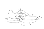
- FIG. 1 is a schematic perspective view showing a shoe of this embodiment.
- a virtual line connecting the tip TT of the toe of the shoe 1 and the most distal end HB of the heel is referred to as a shoe center axis CX, and the direction along the shoe center axis CX is referred to as the “length direction of the shoe”.
- a direction (X1) directed toward the toe side of the shoe 1 in the length direction is referred to as “front”, and a direction (X2) directed toward the heel side is referred to as “rear”.
- the direction (Y) parallel to the horizontal plane among the directions orthogonal to the shoe center axis CX will be referred to as the “width direction” of the shoe
- the direction (Z) parallel to the vertical plane will be referred to as the “height” of the shoe. It is called “direction” or “thickness direction”.
- the direction indicated by the arrow Y1 in the drawing is referred to as “inside”
- the direction indicated by the arrow Y2 is referred to as “outside”.
- the direction indicated by the arrow Z1 in the drawing is referred to as “upper side”
- the direction indicated by the arrow Z2 is referred to as “lower side”.
- the shoe 1 of this embodiment includes an upper material 2 and a shoe sole member 3.
- the shoe 1 is a shoe in which part or all of the upper material 2 is formed of a fiber sheet. In the present embodiment, the entire upper material is formed of a fiber sheet 2a.
- the fiber sheet 2a has heat shrinkability, and the fiber sheet 2a has higher heat shrinkability in the direction perpendicular to the shoe center axis than in the direction along the shoe center axis. It is shown.
- the upper material since the upper material has heat shrinkability, the upper material can be thermally contracted into a shape along the outer surface of the shoe mold corresponding to the space in which the foot is accommodated. Therefore, the shoe shape can be accurately reflected on the upper material.
- the curvature change of the contour of the foot is large, and it is difficult to make the upper material follow the outer surface of the shoe mold in the cross section.
- the shoe of the present embodiment can easily give a shape that fits the foot even in such a part by utilizing the heat shrinkability of the upper material. Further, it is particularly difficult to fit the upper material to the foot in a region where the curvature change of the foot contour is particularly large in the cross section orthogonal to the shoe center axis. That is, when the upper having heat shrinkability is arranged in such a region, the effect of the present invention can be more remarkably exhibited.
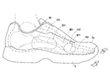
- Examples of the region in which the curvature change of the foot contour is particularly large include the region EA1 corresponding to the arch on the scaphoid bone NB, the medial wedge bone CB1, and the first metatarsal MB1 shown by broken lines in FIG.
- the heat shrinkage rate [100% ⁇ (length before shrinkage ⁇ length after shrinkage) / length before shrinkage] in the shoe center axial direction is set to “x (%)”.
- the thermal contraction rate in the direction perpendicular to the axis is “y (%)”.
- the ratio (y / x) of the heat shrinkage rate in the direction perpendicular to the shoe center axis to the heat shrinkage rate in the shoe center axis direction is more preferably 1.01 or more, and 1.05 or more. Is more preferable, and 1.1 or more is particularly preferable.
- the ratio (y / x) is more preferably 25 or less, further preferably 15 or less, and particularly preferably 10 or less.
- the fiber sheet 2a exhibits a higher heat shrinkage rate when the fiber sheet 2a is heated at a higher temperature for a longer time, it is not preferable to heat the shoe to an excessively high temperature. Therefore, the fiber sheet 2a preferably exhibits the difference in heat shrinkage rate as described above under a heating condition of 160 ° C. ⁇ 60 seconds, and the difference in heat shrinkage rate as described above under a heating condition of 150 ° C. ⁇ 60 seconds. It is more preferable to exhibit the difference in heat shrinkage rate as described above under a heating condition of 140 ° C. ⁇ 60 seconds.
- the thermal contraction rate of the fiber sheet 2a can be obtained from a test piece collected from the upper material 2 of the shoe. Specifically, a test piece is sampled from a portion made of the fiber sheet 2a, a first line passing through the center of the test piece and parallel to the shoe center axis, and passing through the center of the test piece and the first A thermal contraction rate can be obtained by drawing a second line perpendicular to the line on the test piece and comparing the lengths of the two lines before and after thermal contraction. However, the first line and the second line are drawn so as to have the same length as much as possible.
- the fiber sheet 2a of the present embodiment exhibits both the following tensile properties (A) and (B) in at least one direction.
- a 10 mm wide strip-shaped test piece made of the fiber sheet is loaded in the length direction with a tensile energy of 50 mJ, and the energy loss observed when the load is removed is 40% or less.
- the fiber sheet 2a constituting the upper material 2 preferably further exhibits the following tensile properties (C) in the direction having the tensile properties shown in (A) and (B).
- C The elongation of the test piece is 10% or more and 80% or less when a tensile load of 10 kgf is applied in the length direction of the strip-shaped test piece having a width of 10 mm made of the fiber sheet.
- the tensile properties shown in (A) are also simply referred to as “characteristic A”, and the tensile properties shown in (B) are also simply referred to as “characteristic B”.
- the direction in which the fiber sheet 2a exhibits both the characteristics A and B may be referred to as “strengthening direction” or the like.
- the tensile properties shown in (C) may be simply referred to as “characteristic C”.
- the strip-shaped test piece having the characteristic A can be confirmed according to the following method.
- the test piece having a length of about 100 mm is prepared, and stored for several hours or more in a standard state (23 ⁇ 1 ° C., 50 ⁇ 5% RH).
- a standard state 23 ⁇ 1 ° C., 50 ⁇ 5% RH.
- one end of the test piece in the length direction is sandwiched between one of the two chucks of the tensile tester, the distance between the chucks is adjusted to 50 mm, and then the other end of the test piece is sandwiched between the other chuck.
- one of the chucks is moved at a constant speed (10 mm / min) to perform a tensile test of the test piece.
- the strain amount of the test piece is obtained from the moving distance of the chuck, and the tensile energy is calculated from the value of the strain and the value of the tensile stress applied to the test piece.
- the tensile energy value (cumulative value) reaches 50 mJ
- the movement of the chuck is stopped, and then the chuck is moved in the opposite direction at a constant speed (10 mm / min) until the tensile stress value becomes zero.
- a stress-strain curve as shown in FIG. 2 is usually obtained. That is, a stress-strain curve as shown by the curve p is obtained in the section from when the test piece is pulled until the tensile energy reaches 50 mJ, and after the tensile energy reaches 50 mJ, the value of the tensile stress is A stress-strain curve as shown by the curve q is obtained in the interval up to zero.
- the strip-shaped test piece has the characteristic B according to the following method.
- the load P1 (N) when the load applied to the test piece is 50 mJ is obtained.
- a test piece with two marked lines with an interval of 50 mm was stored for several hours or more in the standard state (23 ⁇ 1 ° C., 50 ⁇ 5% RH), and the high cycle with the distance between chucks set to 50 mm
- the test piece is mounted on a fatigue testing machine. At this time, the test piece is mounted on the high cycle fatigue tester so that the edge of the chuck and the marked line coincide.
- a fatigue test is performed by setting a high cycle fatigue tester so that a load of at least “1 (N)” and a maximum of “P1 (N)” is applied to the test piece. That is, after increasing the load of the test piece from 1 (N) to P1 (N), the operation for reducing the load from P1 (N) to 1 (N) is set as one set, and the fatigue test is repeated million times.
- the test environment is a standard state (23 ⁇ 1 ° C., 50 ⁇ 5% RH), and the cycle rate of the fatigue test is 5 Hz.
- Permanent distortion [ ⁇ L (mm) / 50 (mm)] ⁇ 100%
- the strip-shaped test piece has the characteristic C.
- a test piece that has been stored for several hours or more in a standard state (23 ⁇ 1 ° C., 50 ⁇ 5% RH), and place one end of the test piece in the length direction of the two chucks of the tensile tester. After adjusting the distance between chucks to 50 mm, the other end of the test piece is inserted into the other chuck. Then, one of the chucks is moved at a constant speed (10 mm / min) to perform a tensile test of the test piece.
- the “energy loss”, “permanent strain”, and “elongation at a tensile load of 10 kgf” are, for example, the maximum of the results obtained by carrying out the above test so that the number of tests is about 10. It can be obtained as an arithmetic average value of data excluding the value and the minimum value.
- the shoe 1 of the present embodiment follows the shape of the foot even in the case where the stored foot hits the upper material 2 from the inside of the shoe.
- the upper material 2 is deformed, and a comfortable feeling can be given to the user.
- the fiber sheet 2a constituting the upper material 2 has the tensile properties (characteristics A to C) as described above. Accordingly, the shoe 1 is unlikely to be excessively deformed in the upper material 2 even when a large force is applied to the upper material 2 from the inside by the foot.
- the shoe 1 is easy to restore after the upper material 2 is deformed.
- the shoe 1 according to the present embodiment can prevent the user's feet from protruding greatly from the sole to the outside even when used in sports with intense movement. And since the said shoe 1 has a small permanent distortion of the fiber sheet which forms upper material, even if it uses it several times, it is hard to lose shape, and can exhibit the initial stage performance for a long period of time.
- the shoe 1 is such that the reinforcing direction showing the characteristics A and B is within ⁇ 45 ° with respect to the direction perpendicular to the shoe center axis CX. It is preferable that the fiber sheet 2a is arranged.
- the direction along the imaginary line AX is a direction orthogonal to the shoe center axis CX.
- the first range in which the straight line is within ⁇ 45 ° with respect to the virtual line AX is the range indicated by W1 in FIG.
- the second range that is ⁇ 90 ° or more and less than ⁇ 45 ° or more than + 45 ° and less than 90 ° with respect to the imaginary line AX is a range indicated by W2 in FIG.
- the upper material 2 is usually fixed to the shoe sole member 3 at a boundary portion L23 with the shoe sole member 3.
- the tension T1 generated when the point a is pushed from the back side of the upper material 2 and the upper material 2 is deformed in the range W1 of the deformation 1 increases greatly immediately after the upper material 2 starts to deform, but in the second range W2.
- the generated tension T2 has a slow increase in value. Therefore, in the shoe 1 of the present embodiment, it is preferable that the reinforcing direction of the fiber sheet 2a is a direction that passes through the first range W1 in that the upper material 2 can easily exhibit a quick restoring property against deformation. Moreover, in the shoe 1 of this embodiment, it is preferable that the fiber sheet 2a exhibits both the characteristic A and the characteristic B not only in a part of the first range but also in all directions.
- the fiber sheet 2a when the fiber sheet 2a is a woven fabric formed by plain weave or twill weave with warp and weft, the fiber sheet 2a can be obtained by adopting a yarn having excellent strength for one or both of warp and weft.
- the direction of the yarn excellent in strength can be the reinforcing direction in which both characteristics A and B are exhibited.
- the upper material 2 when using the fiber sheet 2a in which the warp direction is the reinforcing direction, the upper material 2 is formed such that the warp direction is within ⁇ 45 ° with respect to the direction perpendicular to the shoe center axis CX.
- the shoes can be suitable for sports with intense movement.
- this warp knitting direction can be the reinforcing direction.
- the fiber sheet 2a is not necessarily arranged in the entire region of the upper material 2 so that the reinforcing direction is within ⁇ 45 ° with respect to the direction orthogonal to the shoe center axis CX, and particularly high strength is required. It may be only the area to be processed.
- Examples of the region in which the reinforcing direction is within a range of ⁇ 45 ° with respect to the direction orthogonal to the shoe center axis CX include, for example, the region EA2 indicated by the broken line in FIG. An area EA3 indicated by a broken line in FIG.
- a joint (first metatarsal joint MP1) between the first phalanx proximal phalange PB1 and the metatarsal bone MB1 is covered from the inside of the foot.
- An area EA2 may be mentioned.
- a region preferably used as the strengthening region for example, as shown by a broken line in FIG. 5, a joint between the fifth phalangeal proximal bone PB5 and the metatarsal bone MB5 (the fifth metatarsal phalanx).
- An area EA3 that covers the joint MP5) from the outside of the foot is mentioned.
- the shoe 1 in the present embodiment has one or more of these two areas EA2 and EA3 as the reinforced area, so that the user's foot is larger than the shoe sole even when used in sports with intense movement. It can prevent more reliably that it protrudes.
- the shoe 1 according to the present embodiment is a woven fabric in which the fiber sheet constituting the upper material 2 is composed of a plurality of yarns in order to make the upper material 2 exhibit excellent strength, or a plurality of yarns.
- a constructed knitted fabric is preferred.
- the fiber sheet 2a of this embodiment is a woven fabric or a knitted fabric, and part or all of the yarn is a fused yarn, and the yarns are fused by the fused yarn.
- the said fiber sheet 2a is arrange
- the strength of the fiber sheet is improved as compared with that before the fusing by fusing the yarns with the fusing yarn. That is, in the fiber sheet, energy loss and permanent distortion tend to be smaller due to the fact that the fused yarns exert forces on each other. Therefore, the shoe provided with such a fiber sheet can more reliably prevent the user's foot from protruding greatly from the sole. Moreover, even when the shoe of this embodiment is used a plurality of times, it is difficult to lose its shape, and it is easier to maintain the initial performance. Further, the upper material has a higher strength than before the fusion and has improved durability.
- the shoe of this embodiment since the fusion thread is arranged along the direction R that circulates around the shoe center axis CX, the upper material is deformed such that the foot protrudes from the sole during exercise. Even if it occurs, a restoring force is likely to be applied to the upper material after deformation in an upward direction and in a direction approaching the shoe center axis. Therefore, the shoe of the present embodiment can more reliably prevent the user's foot from protruding from the shoe sole even when used in sports with intense movement. For this reason, it is preferable that the shoe 1 in the present embodiment has the yarn fused in the reinforcing region.
- the fiber sheet in which the yarns are fused by the fused yarn has one or both of the first heel and the fifth heel having a large movement in the width direction during movement. It is preferable to be disposed in a region covering the middle foot joint joint.
- the deformation of the upper foot covering the part greatly increases with the deformation of the first and fifth heel joints during exercise. Therefore, there is a strong demand for improved durability. Therefore, in the shoe of this embodiment, the durability improvement effect by fusion
- the shoe 1 according to the present embodiment is one of the yarns constituting the fiber sheet when the fiber sheet is a woven fabric or a knitted fabric composed of a plurality of yarns in causing the upper material 2 to exhibit appropriate stretchability. It is preferable that part or all is an elastic yarn made of an elastomer.
- a fusing yarn When a fusing yarn is adopted as a forming material of the fiber sheet 2a of the present embodiment, a general one can be adopted as the fusing yarn.
- the fusion yarn include a monofilament yarn having a core-sheath type and a side-by-side type heat-fusible fiber and composed of only one heat-fusible fiber.
- the fusion yarn include a multifilament yarn including a plurality of the heat-fusible fibers, a multi-filament including one heat-fusible fiber and one or more non-heat-fusible fibers. Examples thereof include filament yarn.
- non-heat-bondable fiber as used herein means a fiber that does not exhibit the bondability even at a temperature at which the heat-bondable fiber can be heat-bonded.
- the heat-fusible fiber is of a core-sheath type and the resin constituting the sheath part is a crystalline resin having a specific melting point (Tm (° C.)
- “non-heat-fusible” “Fiber” means a fiber having at least a surface formed of a crystalline resin having a melting point higher than Tm (° C.) or an amorphous resin having a glass transition temperature higher than Tm (° C.).
- non-heat-fusible means a fiber having at least a surface formed of a crystalline resin having a melting point higher than Tg (° C.) or an amorphous resin having a glass transition temperature higher than Tg (° C.). To do.
- the melting point and glass transition temperature of the core part and the sheath part of the heat-fusible fiber and the melting point and glass of the resin that forms the surface of the sheath part of the heat-fusible fiber and the non-heat-fusible fiber is preferably 20 ° C. or higher and 150 ° C. or lower, more preferably 30 ° C. or higher and 120 ° C. or lower.
- the melting point and glass transition temperature of the resin can be confirmed by performing differential scanning calorimetry (DSC) at a rate of temperature increase of 10 ° C./min.
- DSC differential scanning calorimetry
- the fusing yarn does not need to be a continuous fiber, and may be a spun yarn produced by spinning a relatively short (for example, 2 m or less) fusing fiber.
- the fusion yarn may be a blend of different heat-fusible fibers, or a blend of heat-fusible fibers and non-heat-fusible fibers. Also good.
- the heat-fusible fiber those produced so as to be the core-sheath type or the side-by-side type using two or more kinds of polymers having different melting points or softening points can be employed. More specifically, as the heat-fusible fiber, for example, a crystalline polyester resin such as a polyethylene terephthalate resin is used to form a core, and a crystalline polyester resin having a lower melting point than the polyester resin, or the polyester A core-sheath fiber having a sheath formed of an amorphous polyester resin having a glass transition temperature lower than the melting point of the resin, and a crystalline polyamide resin having a lower melting point than the polyester resin, the core of which is formed by a crystalline polyester resin And a core-sheath type fiber in which a sheath part is formed.
- a crystalline polyester resin such as a polyethylene terephthalate resin is used to form a core
- a crystalline polyester resin having a lower melting point than the polyester resin or the polyester A core
- the elastic yarn When the elastic yarn is employed as the material for forming the fiber sheet 2a of the present embodiment, a general material can be employed as the elastic yarn.
- the elastic yarn includes an elastic fiber formed of an elastomer, a monofilament yarn composed of only one elastic fiber, a multifilament yarn including a plurality of elastic fibers, one elastic fiber and one or more. And a multifilament yarn having a non-elastic fiber.
- the elastomer constituting the elastic yarn has a tensile elongation at break of 50% or more in a standard state (23 ⁇ 1 ° C., 50 ⁇ 5% RH), and an elongation elastic recovery rate at 10% elongation of 80%. What shows the elastic restoring property used as the above is preferable.
- the elastic yarn When the elastic yarn is a monofilament yarn, usually the tensile properties of the elastomer directly affect the tensile properties of the yarn. Therefore, when the elastic yarn is a monofilament yarn, the elastic yarn usually exhibits the same tensile elongation at break and elastic resiliency as the elastomer. In the present embodiment, even when the elastic yarn is a multifilament yarn, the elastic yarn preferably has such tensile elongation at break and elastic resilience.
- a core-sheath fiber is formed by two types of polyester thermoplastic elastomers having different melting points and glass transition temperatures, and a sheath is formed by a polyester thermoplastic elastomer having a low melting point or glass transition temperature.
- polyester-based thermoplastic elastomers useful for producing such a fused yarn and an elastic yarn include, for example, a part of a diol or dicarboxylic which is a constituent unit of a polymer is changed to another diol or dicarboxylic.
- examples thereof include a polyester resin that has been modified to exhibit rubber elasticity, and a polyester resin that exhibits rubber elasticity by introducing a partially crosslinked structure.
- the fiber may have a core portion formed of a polyester thermoplastic elastomer and a sheath portion formed of a polyamide thermoplastic elastomer having a melting point and a glass transition temperature lower than those of the polyester thermoplastic elastomer. good.
- the core portion is a polyester elastomer having a melting point of 190 ° C. or higher and 250 ° C. or lower, and the sheath portion has a melting point of 140 ° C. or higher and 190 ° C. or lower.
- a core-sheath fiber made of a polyester elastomer is preferred.
- the said fiber sheet 2a has the heat shrinkability in the point in which the shoe 1 in this embodiment can provide a desired shape to the upper material 2 easily.
- the shoe 1 according to the present embodiment covers the upper material produced so that the fiber sheet 2a has a heat-shrinkable property so as to be close to the final shape to some extent on the mold corresponding to the space for accommodating the foot.
- the upper material can be thermally shrunk into a shape along the outer surface of the mold. That is, since the fiber sheet 2a has heat shrinkability, it is possible to easily manufacture a shoe having excellent shape accuracy. Further, since the fiber sheet 2a has heat shrinkability, it becomes easy to finely adjust the upper material of the shoe once produced according to the shape of the user's foot.
- the fiber sheet exhibits higher heat shrinkability in the width direction than in the shoe length direction. That is, it is preferable that the upper material exhibits a higher heat shrinkage rate in the second direction perpendicular to the first direction than in the first direction from the heel toward the toe.
- the curvature change of the contour of the foot is particularly large in the cross section orthogonal to the shoe center axis. For this reason, it is generally difficult to fit the upper material to the foot in the region corresponding to the arch (the portion covering the inner wedge bone).
- the shoe of this embodiment can be easily fitted to the foot even in such a region due to the heat shrinkability of the upper material. That is, in the above aspect in which the heat shrinkability is exhibited at such a site, the effect of the present invention can be exhibited more remarkably.
- the upper material 2 fits with respect to a leg
- Examples include an area EA2 that covers from the inside, and an area EA3 that covers the joint (fifth metatarsal joint MP5) between the proximal phalanx PB5 of the fifth heel and the metatarsal bone MB5 from the outside of the foot.
- a shrink yarn containing fibers exhibiting heat shrinkability may be employed as a constituent material of the fiber sheet 2a.
- the heat-shrinkable fibers constituting the shrink yarn are preferably those whose length after being heated and shrunk is 90% or less of the length before heating, and more preferably 85% or less.
- the shrink yarn is preferably such that the length after being heated and shrunk is 90% or less of the length before heating, and more preferably 85% or less.
- the shrinkage ratio of fibers and yarns is obtained, for example, by comparing the lengths of fibers and yarns stored in the standard state (23 ⁇ 1 ° C., 50 ⁇ 5% RH) for several hours or more in the natural state before and after heating.
- the shrink yarn preferably has a shrinkage stress per unit thickness in the range of 150 ° C. or more and 210 ° C. or less of 0.05 cN / dtex or more and 2.00 cN / dtex.
- the polyethylene terephthalate resin usually has a crystallization temperature of around 150 ° C. and a melting point of 200 ° C. or higher. And the fiber obtained by cooling while heat-melting polyethylene terephthalate resin is made into a fiber form can be made into an amorphous state by implementing the said rapid cooling.
- Such polyethylene terephthalate resin fibers usually exhibit high heat shrinkability due to molecular rearrangement when heated above the crystallization temperature. Therefore, it is preferable that the shrink yarn includes a fiber excellent in heat shrinkage such as polyethylene terephthalate resin fiber.
- Such heat shrinkage is not only a polyethylene terephthalate resin that is a condensation polymer of terephthalic acid and ethylene glycol, but also a type of polyethylene terephthalate resin in which a part of terephthalic acid is replaced with another dicarboxylic acid, ethylene
- a polyethylene terephthalate resin of a type in which a part of glycol is replaced with another diol is changed from a part of terephthalic acid to another dicarboxylic acid such as isophthalic acid in that it is easy to exert excellent heat shrinkability on the shrink yarn.
- a polyethylene terephthalate resin in which a part of ethylene glycol is changed to another diol such as 2,2-bis (4-hydroxyphenyl) propane is preferable.
- the fiber sheet 2a When the fiber sheet 2a is a woven fabric, the fiber sheet 2a can exhibit heat shrinkability by using a part of the warp or weft as the polyethylene terephthalate resin fiber.
- the fiber sheet 2a preferably exhibits heat shrinkability not only in one direction but also in multiple directions, and it is preferable to use both warp and weft as shrink yarns.
- the heat shrinkability of the fiber sheet 2a can be adjusted by the ratio of polyethylene terephthalate resin fibers in the warp and weft. At that time, the ratio of polyethylene terephthalate resin fibers may be different between one warp and another warp, or the ratio of polyethylene terephthalate resin fibers may be different between one weft and another weft. 2a may be provided with an appropriate ratio of warps and wefts not containing polyethylene terephthalate resin fibers.
- the fiber sheet 2a is a knitted fabric, and the heat shrinkability can be adjusted by the content of the polyethylene terephthalate resin fiber.
- the fused yarn, the elastic yarn, and the shrinkable yarn usually have a total fineness of 20 dTex or more and 5000 dTex or less, depending on the use of shoes.
- the total fineness of these yarns is preferably 30 dTex or more and 2000 dTex or less.
- the fiber sheet 2a is a woven fabric formed by warps and wefts, and the fiber sheet 2a is formed of fused yarns, the warp yarns and the weft yarns are usually melted at the intersection of each other. Will be worn.
- the fiber sheet 2a it is advantageous for the characteristics A, the characteristics B, and the characteristics C to be appropriately adjusted so that the number of fusion points per unit area is appropriately adjusted. Therefore, the fiber sheet 2a is JIS L 1096 (2010). 8.6.1 It is preferable that the weave density of warps and wefts measured according to the A method is 10 yarns / 2.54 cm or more and 200 yarns / 2.54 cm or less.
- FIG. 6 schematically shows a state in which the fiber sheet 2a ′, which is a knitted fabric constituting the upper material 2, is viewed from the front side of the shoe 1, and the fiber sheet 2a ′ has a size of about 1 mm 2 .
- FIG. 7 schematically shows a state in which the fiber sheet 2a ′ is viewed from the back side (inside the shoe) of the upper material 2, and as shown in these drawings, the fiber sheet 2a ′. Is knitted with a plurality of yarns.
- the fiber sheet 2 a ′ includes a plurality of string-like bodies 21, and a plurality of finely meandering string-like bodies 21 are arranged in parallel with a slight gap, and a gap portion between the string-like bodies 21 is provided.
- the through-hole 20 is provided in the above.
- the fiber sheet 2 a ′ of the present embodiment has an appearance as if it was made only of the string-like body 21, but actually, the elastic yarn 22 that is a colorless and transparent monofilament yarn thinner than the string-like body 21 The shrink yarn 23 further thinner than the elastic yarn is further provided.
- the elastic yarn 22 and the shrink yarn 23 in the fiber sheet 2a ′ of the present embodiment are fusion yarns having heat fusion properties.
- the string-like body 21 is arranged in a state along a direction R that circulates around the shoe center axis CX.
- the elastic yarns 22 are arranged so that the length direction thereof is parallel to the shoe center axis CX, and are arranged in parallel at intervals in the shoe width direction. That is, the elastic material 22 is arranged on the upper material 2 so as to skew the string-like body 21.
- the plurality of the string-like bodies 21 are arranged in parallel at intervals, so that the gap between the string-like bodies 21 and the gap between the elastic yarns 22 are arranged.
- the portion where and overlap is the through hole 20.
- the shrink yarn 23 is partly knitted into the string-like body 21 and partly entangled with the elastic yarn 22. Therefore, the upper material 2 is in a state in which the string-like body 21, the elastic yarn 22, and the shrink yarn 23 are fixed to each other.
- the said string-like body 21 is comprised by the three fine strings 211, 212, 213 thinner than the said string-like body 21, and is formed by aligning three fine strings.
- the three thin cords 211, 212, and 213 have different colors, and yarns of different colors are chain-knitted.
- the first thin string 211 of the three thin strings is on the surface side of the shoe, and the second thin string 212 and the third thin string 213 are on the inner surface side of the shoe.
- a plurality of string-like bodies 21 are arranged so as to be.
- the second thin string 212 is arranged on the front side of the shoe with respect to the third thin string 213.
- the upper material 2 of the present embodiment when the fiber sheet 2a ′ is viewed from the front, appears to be formed only by the first thin cord 211, but the fiber sheet 2a ′ is formed from the front of the shoe.
- the second thin string 212 can be visually recognized through the gap between the string-like bodies 21.
- the upper material 2 of this embodiment can visually recognize the 3rd thin string 213 through the clearance gap between the string-like bodies 21, when the fiber sheet 2a 'is seen from the back of shoes.
- the shoe of the present embodiment exhibits different colors depending on the viewing angle because the second fine string 212 and the third fine string 213 have different colors.
- the shoe of this embodiment extends in the direction R around the shoe center axis CX and has a plurality of string-like bodies 21 arranged in parallel with a gap in the shoe center axis direction.
- the string-like body 21 includes three or more fine strings including a first fine string 211, a second fine string 212, and a third fine string 213 that are thinner than the string-like body 21.
- the first thin string 211 is arranged on the surface of the upper material 2 and the second fine string 212 and the third fine string 213 are arranged on the back side of the first fine string 211.
- the second thin string 212 is arranged along one side edge of both side edges of the first thin string 211, and is different in color from the second thin string 212 along the other side edge.
- the third fine string 213 is arranged to have an excellent aesthetic appearance.
- the upper material 2 in the present embodiment can exhibit an excellent aesthetic appearance by the fiber sheets 2a and 2a ′ as described above, and can also exhibit an excellent aesthetic appearance by a member other than the fiber sheets 2a and 2a ′.
- the resin film is useful for smoothing the surface of the upper material.
- a resin film is easy to print a pattern and a character compared with a fiber sheet.
- the pattern and characters can be provided on the resin film by embossing or the like. Therefore, if at least a part of the upper material is composed of a composite sheet including a fiber sheet and a resin film, it is possible to cause the upper material to exhibit a texture that is difficult to appear only with the fiber sheet.
- the upper material further includes a resin film bonded to one or both sides of the fiber sheet in terms of widening design options.
- the resin film may be colored in various colors.
- the resin film may contain extender pigments in consideration of concealment.
- the resin film is preferably arranged so as to be exposed on at least one of the outer surface and the inner surface of the shoe, and more preferably arranged so as to be exposed on the outer surface of the shoe.
- a reactive adhesive that is liquid at normal temperature (for example, 23 ° C.), a hot-melt adhesive that is solid at normal temperature, a pressure-sensitive adhesive that is semisolid at normal temperature, and the like.
- a hot melt adhesive as the adhesive.
- the resin film may be obtained by processing a hot melt adhesive into a film.
- the resin film formed entirely with a hot melt adhesive softens the whole when thermally bonded to the fiber sheet, so that irregularities are likely to be formed on the surface opposite to the adhesive surface with the fiber sheet. Become. Then, when a pattern, a character, etc. are printed beforehand, these shapes will collapse. Even when a pattern or character is printed later, it is difficult to perform good printing if the surface is uneven. Therefore, the resin film is made of an amorphous resin having a higher softening point than that of the hot melt adhesive, or a film layer and a hot melt adhesive made of a crystalline resin having a melting point higher than that of the hot melt adhesive. It is preferable that it is a multilayer film provided with the contact bonding layer comprised by these.
- the hot melt adhesive preferably includes a polyester polyurethane resin from the viewpoint of adhesiveness to the fiber sheet.
- the resin film and the fiber sheet are brought into contact with each other, it is advantageous for the adhesion between the resin film and the fiber sheet to exhibit high adhesive strength when there are more contacts between them. . This is the same except when a hot melt adhesive is used.
- the said fiber sheet is the woven fabric or knitted fabric comprised by the some thread
- the bulky processed yarn for example, a yarn obtained by applying heat to a twisted multifilament yarn to give crimpability and then returning the twist can be adopted.
- This type of bulky processed yarn is also called wooly yarn or the like and has a texture like wool.
- This bulky processed yarn is suitable as a yarn constituting the fiber sheet because it is supple and has a good feel to the foot.
- the elastic yarn, the shrink yarn, and the like are more easily exhibited as monofilament yarns. Therefore, for example, when the above-described monofilament yarn is used as the weft, 5% to 95% of the total number of wefts is the monofilament yarn, and the rest (95% to 5%) is the bulky processed yarn.
- the ratio of the bulky processed yarn to the total number of weft yarns is more preferably 10% or more and 90% or less, further preferably 15% or more and 85% or less, and more preferably 20% or more and 80% or less. Particularly preferred.
- 50% or more of the total number is preferably a bulky processed yarn, and more preferably 60% or more is a bulky processed yarn.
- the resin film does not excessively affect the stretchability of the fiber sheet.
- the tensile stress (N) of the resin film is the tensile stress (N when the fiber sheet alone is pulled in the direction of the warp or weft by the same distance. ) Is preferably smaller than.
- the tensile stress (N) of the resin film is preferably smaller than the tensile stress (N) when the fiber sheet is pulled in the course or wale direction.
- the tensile stress (N) of the resin film is preferably a value lower than the lowest value when the tensile stress of the fiber sheet is determined in various directions.
- the tensile stress (N) of the resin film and the tensile stress of the fiber sheet are obtained by preparing a strip-shaped sample (for example, 10 mm width) of the same width and conducting a tensile test of the sample with a tensile tester. be able to. More specifically, the tensile stress of the resin film or the fiber sheet is obtained by setting the distance between chucks of the tensile tester to 25 mm, and obtaining the stress when the sample is sandwiched between the chucks and the sample is stretched by 5%. be able to.
- the tensile stress (N) of the resin film is preferably 75% or less of the minimum value, and more preferably 50% or less.
- the thickness of the resin film is usually 1 ⁇ m or more and 250 ⁇ m or less.
- the thickness is preferably 5 ⁇ m or more and 200 ⁇ m or less.
- the fiber sheet which shows heat-shrinkability with a shrinkable yarn is used for formation of the upper material 2 as mentioned above, it is easy to produce the shoe 1 of this embodiment in a desired shape.
- the shoe 1 according to the present embodiment can be manufactured, for example, by covering the upper material with a shoe mold and performing a molding process for deforming the upper material along the shoe mold.
- the forming step is performed using an upper material provided with a heat-shrinkable fiber sheet. Therefore, in the forming step, the upper material covered on a shoe mold is heated, The upper material can be deformed along the shoe mold by thermally shrinking the fiber sheet.
- the shape of the shoe mold can be accurately reflected on the upper material.
- a fiber sheet having different heat shrinkability in one direction and the other direction orthogonal to the direction is used as the fiber sheet, and along the shoe center axis. It is preferable to carry out the forming step by arranging the fiber sheet so that the direction perpendicular to the shoe center axis is higher in heat shrinkability than the direction in which the fiber sheet is stretched.
- a part or all of the upper material is a shoe formed of a fiber sheet, the fiber sheet has heat shrinkability, and the fiber sheet is a shoe center. It is possible to obtain a shoe exhibiting higher heat shrinkage in the direction orthogonal to the shoe center axis than in the direction along the axis.
- the upper material since the upper material has heat shrinkability, the upper material can be thermally contracted into a shape along the outer surface of the shoe mold corresponding to the space in which the foot is accommodated. Therefore, the shoe shape can be accurately reflected on the upper material.
- the curvature change of the contour of the foot is large, and it is particularly difficult to make the upper material follow the outer surface of the shoe mold in the cross section.
- the shoe of the present embodiment can easily give a shape that fits the foot even in such a part by utilizing the heat shrinkability of the upper material. Such shoes are not only easy to produce in the desired shape, but also when the shape of the upper material needs to be fine-tuned according to the user's foot after production.
- the shoe manufacturing method of the present embodiment after producing a shoe having an upper material having a shape corresponding to one shoe mold, another shoe mold having a shape different from the one shoe mold is used as the upper material.
- the upper material can be changed to a shape corresponding to the other shoe mold by heating it against the back side.
- the one shoe mold A larger shoe mold may be accommodated in the shoe, and the upper material may be extended by applying a force to the upper material from the back side.
- selecting shoes according to the foot length becomes cramped in the foot width direction, and conversely selecting shoes according to the foot width. Then, although an extra space may be generated in the toe portion, the shoe of this embodiment can suppress the occurrence of this type of problem because the shape of the upper material can be adjusted.
- the fit in the width direction of the foot can be adjusted by the tightening of the shoelace in the conventional shoe, but if the foot is instep, the tongue in the conventional shoe is large. In some cases, the appearance of shoes may be reduced due to exposure. Since the shoe of this embodiment can adjust the shape of an upper material, it can also suppress that this kind of problem arises. Further, the shoe of the present embodiment is used by the user and loses its shape, so that even after the upper material is deformed into a shape different from the new state immediately after manufacture, the shoe mold is applied from the back side of the upper material. By heating in contact, the upper material can be made into a shape corresponding to the shoe shape, and the upper material can be restored to a shape close to that immediately after manufacture. Thus, the shoe of this embodiment has an advantage that repair is easy.
- the fused yarn can be heat-sealed to another yarn in the molding step. Therefore, according to the shoe manufacturing method of the present embodiment, for example, the fiber sheet is a woven fabric or a knitted fabric composed of a plurality of yarns, and a part or all of the yarns are fused yarns. Thus, it is possible to obtain a shoe in which yarns are fused. That is, according to the shoe manufacturing method of the present embodiment, a shoe having excellent strength can be obtained. In that case, as described above, an upper material in which the fiber sheet in which threads are fused is arranged on a portion covering one or more of the first metatarsal joint and the fifth metatarsal joint. By making it, it is possible to obtain a shoe that does not lose its shape even when used for intense exercise.
- the shoe of the present embodiment is not only easy to be out of shape and excellent in comfort, but also excellent in terms of easy manufacture.
- the description which concerns on the said embodiment is an illustration to the last, The shoes which concern on this invention, and its manufacturing method are not limited to the said embodiment at all. That is, the shoes according to the present invention can be variously modified without departing from the gist of the present invention.
Abstract
本発明の課題は、所望の形状となるように製造することが容易な靴を提供することである。本発明は、アッパー材の一部又は全部が繊維シートで形成された靴であって、前記繊維シートが特定の熱収縮性を有する靴を提供する。
Description
本願は、日本国特願2015-255819号の優先権を主張し、引用によって本願明細書の記載に組み込まれる。
本発明は、靴に関し、より詳しくは、アッパー材の一部又は全部が繊維シートで形成された靴に関する。
従来、天然皮革や合成皮革によって作製されたアッパー材を有する革靴は、多くの人々に利用されている。
一方、ジョギングなどに用いられる靴においては、通気性や軽量性などの観点からアッパー材の形成に織地や編地などの繊維シートが利用されている(下記特許文献1参照)。
一方、ジョギングなどに用いられる靴においては、通気性や軽量性などの観点からアッパー材の形成に織地や編地などの繊維シートが利用されている(下記特許文献1参照)。
一般に繊維シートで出来たアッパー材を備えた靴は、皮靴などに比べて軽量性に優れている。
また、この種の靴は、通常、足に加わった力に応じてアッパー材が変形し易くスポーツなどに使用した場合でも使用者にとって快適なものとなる。
ところで、この種の靴は、通常、平坦な繊維シートが所定形状に裁断され、該繊維シートが縫製されて立体的な形状を有するアッパー材が作製された後で該アッパー材と靴底用部材とが接着されて作製される。
しかしながら、人の足の形状は複雑な曲面からなっているためアッパー材を使用者の足に十分にフィットさせることは容易ではない。
即ち、従来の靴は、所望の形状に製造することが容易ではないという問題を有している。
そして、このような問題については十分な解決策が見出されていない。
本発明は、このような問題を解決することを課題としており、所望の形状となるように製造することが容易な靴を提供することを目的としている。
上記課題を解決すべく本発明は、アッパー材の一部又は全部が繊維シートで形成された靴であって、前記繊維シートは、熱収縮性を有し、且つ、シューセンター軸に沿った方向よりも、シューセンター軸に直交する方向の方が高い熱収縮性を示す靴を提供する。
以下においては、スニーカーを例示しつつ本発明に係る靴の実施形態を説明する。
図1は、本実施形態の靴を示した概略斜視図である。
なお、以下においては、当該靴1の爪先の最先端TTと踵の最末端HBとを結ぶ仮想線をシューセンター軸CXと称し、該シューセンター軸CXに沿った方向を靴の“長さ方向”と称する。
そして、この長さ方向における靴1の爪先側に向けた方向(X1)を“前方”と称し、踵側に向けた方向(X2)を“後方”と称する。
また、以下においては前記シューセンター軸CXに直交する方向の内、水平面と平行する方向(Y)を靴の“幅方向”と称し、垂直面と平行する方向(Z)を靴の“高さ方向”又は“厚み方向”と称する。
そして、以下においては、“幅方向”の内、図中に矢印Y1で示されている方向を“内側”、矢印Y2で示されている方向を“外側”と称する。
また、以下においては、“高さ方向”又は“厚み方向”の内、図中に矢印Z1で示されている方向を“上側”、矢印Z2で示されている方向を“下側”と称する。
図に示されているように本実施形態の靴1は、アッパー材2と靴底用部材3とを有している。
前記靴1は、アッパー材2の一部又は全部が繊維シートで形成された靴であり、本実施形態においてはアッパー材全体が繊維シート2aで形成されている。
前記靴1は、アッパー材2の一部又は全部が繊維シートで形成された靴であり、本実施形態においてはアッパー材全体が繊維シート2aで形成されている。
本実施形態においては、前記繊維シート2aが熱収縮性を有しており、前記繊維シート2aは、シューセンター軸に沿った方向よりもシューセンター軸に直交する方向の方が高い熱収縮性を示すものである。
本実施形態においては、アッパー材が熱収縮性を有することで、当該アッパー材を、足を収容させる空間に対応した靴型の外表面に沿わせた形に熱収縮させることができる。
よって、アッパー材に靴型の形状を正確に反映させることができる。
なお、一般にシューセンター軸に直交する断面においては、足の輪郭の曲率変化が大きく、該断面において、アッパー材を靴型の外表面に沿わせることが難しい。
本実施形態の靴は、アッパー材の熱収縮性を利用してこのような部位においても足にフィットした形状を付与することが容易である。
また、シューセンター軸に直交する断面において、足の輪郭の曲率変化が特に大きい領域では、アッパー材を足にフィットさせることは特に難しい。
即ち、このような領域に熱収縮性を有するアッパーを配すると、本発明の効果がより顕著に発揮され得る。
足の輪郭の曲率変化が特に大きい領域としては、例えば、図4に破線で示した舟状骨NB、内側楔状骨CB1、第1中足骨MB1にかけての土踏まずに対応する領域EA1が挙げられる。
前記繊維シート2aは、シューセンター軸方向での熱収縮率[100%×(収縮前の長さ-収縮後の長さ)/収縮前の長さ]を「x(%)」とし、シューセンター軸に直交する方向の熱収縮率を「y(%)」とした場合、下記の関係を満たすことが好ましい。
1 < (y/x)
なお、シューセンター軸方向での熱収縮率に対するシューセンター軸に直交する方向の熱収縮率の比率(y/x)は、1.01以上であることがより好ましく、1.05以上であることが更に好ましく、1.1以上であることが特に好ましい。また、前記比(y/x)は、25以下であることがより好ましく、15以下であることが更に好ましく、10以下であることが特に好ましい。
1 < (y/x)
なお、シューセンター軸方向での熱収縮率に対するシューセンター軸に直交する方向の熱収縮率の比率(y/x)は、1.01以上であることがより好ましく、1.05以上であることが更に好ましく、1.1以上であることが特に好ましい。また、前記比(y/x)は、25以下であることがより好ましく、15以下であることが更に好ましく、10以下であることが特に好ましい。
前記繊維シート2aは、繊維シート2aをより高い温度でより長時間加熱した方が高い熱収縮率を示すものの靴を過度に高温に加熱することは好ましいことではない。
そのため、前記繊維シート2aは、160℃×60秒の加熱条件において上記のような熱収縮率の違いを発揮することが好ましく150℃×60秒の加熱条件において上記のような熱収縮率の違いを発揮することがより好ましく140℃×60秒の加熱条件において上記のような熱収縮率の違いを発揮することが特に好ましい。
そのため、前記繊維シート2aは、160℃×60秒の加熱条件において上記のような熱収縮率の違いを発揮することが好ましく150℃×60秒の加熱条件において上記のような熱収縮率の違いを発揮することがより好ましく140℃×60秒の加熱条件において上記のような熱収縮率の違いを発揮することが特に好ましい。
ここで繊維シート2aの熱収縮率については、靴のアッパー材2から採取したテストピースにより求めることができる。
具体的には、繊維シート2aで出来た部位からテストピースを採取し、該テストピースの中心部を通り且つシューセンター軸に平行する第1の線と、テストピースの中心部を通り且つ第1の線に直交する第2の線とをテストピースに描き、両線の熱収縮前後の長さを比較することによって熱収縮率を求めることができる。
ただし、第1の線と第2の線とはできるだけ長さが同じになるように描き、テストピースが自然状態において湾曲している場合は、第1の線の初期長さ(L10:mm)や第2の線の初期長さ(L20:mm)は、このままの状態で測定することとする。
即ち、第1の線や第2の線の長さは、湾曲に沿って測定するものとする。
また、熱収縮試験後にテストピースの湾曲がひどくなったり、或いは、逆にテストピースが平坦化したりする場合でも、熱収縮後の第1の線の長さ(L11:mm)や熱収縮後の第2の線の長さ(L21:mm)は、テストピースを自然状態にして測定することとする。
そして、これらの測定結果に基づいて各方向での熱収縮率を下記のようにして求めることができる。
x=(L10-L11)/L10 × 100(%)
y=(L20-L21)/L20 × 100(%)
また、本実施形態の前記繊維シート2aは、少なくとも一方向において下記(A)及び(B)の両方の引張特性を示すものである。
(A)前記繊維シートからなる幅10mmの短冊状の試験片に対して50mJの引張エネルギーで長さ方向に負荷を与え、該負荷を取り除いた際に観察されるエネルギーロスが40%以下。
(B)前記繊維シートからなる幅10mmの短冊状の試験片を長さ方向に引張って引張エネルギーが50mJとなる歪み量を求め、該歪み量での変形と復元とを百万回繰り返した後の前記試験片の永久歪みが10%以下。
(A)前記繊維シートからなる幅10mmの短冊状の試験片に対して50mJの引張エネルギーで長さ方向に負荷を与え、該負荷を取り除いた際に観察されるエネルギーロスが40%以下。
(B)前記繊維シートからなる幅10mmの短冊状の試験片を長さ方向に引張って引張エネルギーが50mJとなる歪み量を求め、該歪み量での変形と復元とを百万回繰り返した後の前記試験片の永久歪みが10%以下。
アッパー材2を構成する前記繊維シート2aは、前記の(A)、(B)に示した引張特性を有する方向において、さらに、下記(C)の引張特性を示すものであることが好ましい。
(C)前記繊維シートからなる幅10mmの短冊状の試験片の長さ方向に10kgfの引張荷重を与えた際の該試験片の伸びが10%以上80%以下。
(C)前記繊維シートからなる幅10mmの短冊状の試験片の長さ方向に10kgfの引張荷重を与えた際の該試験片の伸びが10%以上80%以下。
なお、以下においては(A)に示した引張特性を単に「特性A」とも称し、(B)に示した引張特性を単に「特性B」とも称する。
また、以下においては、繊維シート2aが特性Aと特性Bとの両方を発揮する方向を、「強化方向」などと称することがある。
さらに、以下においては(C)に示した引張特性を単に「特性C」と称することがある。
また、以下においては、繊維シート2aが特性Aと特性Bとの両方を発揮する方向を、「強化方向」などと称することがある。
さらに、以下においては(C)に示した引張特性を単に「特性C」と称することがある。
前記短冊状の前記試験片が特性Aを有することは、具体的には、下記の方法に従って確認することができる。
まず、長さ100mm程度の前記試験片を用意し、これを標準状態(23±1℃、50±5%RH)で数時間以上保管する。次にこの試験片の長さ方向一端部を引張試験機の2つのチャックの内の一方に挟み込み、チャック間距離を50mmに調整した後にもう一方のチャックに試験片の他端部を挟み込む。
そして、一方のチャックを一定速度(10mm/min)で移動させて試験片の引張試験を実施する。
このときチャックの移動距離から試験片の歪み量を求め、歪みの値と試験片に加わる引張応力の値とによって引張エネルギーを算出する。そして、引張エネルギーの値(累積値)が50mJとなった時点でチャックの移動を停止させ、次いで、引張応力の値がゼロになるまでチャックを反対方向に一定速度(10mm/min)で移動させる。
この際、通常、図2に示したような応力-歪み曲線が得られる。
即ち、試験片の引張を開始してから引張エネルギーが50mJとなるまでの区間において曲線pで示したような応力-歪み曲線が得られ、引張エネルギーが50mJとなった後、引張応力の値がゼロになるまでの区間において曲線qで示したような応力-歪み曲線が得られる。
そして、2つの曲線(曲線p,曲線q)とx軸とで囲まれた区間の面積(Sa)から損失エネルギー(ΔE:mJ)を算出することができ、前記特性Aにおける「エネルギーロス」は下記計算によって求めることができる。
エネルギーロス(%)=[(ΔE)/50(mJ)]×100%
即ち、試験片の引張を開始してから引張エネルギーが50mJとなるまでの区間において曲線pで示したような応力-歪み曲線が得られ、引張エネルギーが50mJとなった後、引張応力の値がゼロになるまでの区間において曲線qで示したような応力-歪み曲線が得られる。
そして、2つの曲線(曲線p,曲線q)とx軸とで囲まれた区間の面積(Sa)から損失エネルギー(ΔE:mJ)を算出することができ、前記特性Aにおける「エネルギーロス」は下記計算によって求めることができる。
エネルギーロス(%)=[(ΔE)/50(mJ)]×100%
また、短冊状の前記試験片が特性Bを有することは、具体的には、下記の方法に従って確認することができる。
まず、試験片が特性Aを有することを確認する方法において得られる「応力-歪み曲線」から、試験片に加わる負荷が50mJとなる際の荷重P1(N)を求める。
次いで、50mmの間隔を設けた2本の標線を記入した試験片を標準状態(23±1℃、50±5%RH)で数時間以上保管し、チャック間距離を50mmにセットした高サイクル疲労試験機に該試験片を装着する。
このときチャックの端縁と標線とが一致するようにして試験片を高サイクル疲労試験機に装着する。
そして、試験片に対し、最低「1(N)」、最高「P1(N)」の荷重が加わるように高サイクル疲労試験機を設定して疲労試験を実施する。
即ち、試験片の荷重を1(N)からP1(N)まで増大させた後に前記荷重をP1(N)から1(N)まで低減させる操作を1セットとし、これを百万回繰り返す疲労試験を実施する。
なお、試験環境は標準状態(23±1℃、50±5%RH)とし、疲労試験のサイクル速度は、5Hzとする。
そして、疲労試験が終わった後の試験片の標線間距離を測定することで初期の標線間距離(50mm)からの伸び量(ΔL:mm)を測定することができ、前記特性Bにおける「永久歪み」は下記計算によって求めることができる。
永久歪み(%)=[ΔL(mm)/50(mm)]×100%
さらに、短冊状の前記試験片が特性Cを有することは、具体的には、下記の方法に従って確認することができる。
まず、標準状態(23±1℃、50±5%RH)で数時間以上保管しておいた試験片を用意し、該試験片の長さ方向一端部を引張試験機の2つのチャックの内の一方に挟み込み、チャック間距離を50mmに調整した後にもう一方のチャックに試験片の他端部を挟み込む。
そして、一方のチャックを一定速度(10mm/min)で移動させて試験片の引張試験を実施する。
そして、引張荷重が10kgfとなった時点でチャックの移動を停止し、このときのチャック間距離から当初チャック間距離(50mm)を差し引いて試験片の伸び量(ΔE:mm)を求め、試験片が特性Cを有することは、下記計算を行うことによって確認することができる。
引張荷重10kgfでの伸び(%)=[ΔE(mm)/50(mm)]×100(%)
なお、「エネルギーロス」、「永久歪み」、及び、「引張荷重10kgfでの伸び」は、例えば、試験回数が10回程度となるように上記試験を実施し、得られた結果の内の最大値と最小値とを除いたデータの算術平均値として求めることができる。
本実施形態の靴1は、アッパー材2が繊維シート2aで形成されているため、収容した足が靴の内側からアッパー材2に強く当たってしまうような場合においても、足の形に追従するようにアッパー材2が変形し、使用者に快適感を与えることができる。
しかも、前記靴1は、アッパー材2を構成する繊維シート2aが上記のような引張特性(特性A~C)を有している。
従って、前記靴1は、足によってアッパー材2に内側から大きな力が加えられた場合でも当該アッパー材2に過大な変形が生じ難い。
また、前記靴1は、アッパー材2が変形後に復元し易い。
そのため、本実施形態における前記靴1は、動きの激しいスポーツなどに用いた場合においても使用者の足が靴底から外側に大きくはみ出してしまうことを防ぐことができる。
そして、前記靴1は、アッパー材を形成する繊維シートの永久歪みが小さいため、複数回使用しても型崩れしにくく、初期の性能を長期持続的に発揮することができる。
しかも、前記靴1は、アッパー材2を構成する繊維シート2aが上記のような引張特性(特性A~C)を有している。
従って、前記靴1は、足によってアッパー材2に内側から大きな力が加えられた場合でも当該アッパー材2に過大な変形が生じ難い。
また、前記靴1は、アッパー材2が変形後に復元し易い。
そのため、本実施形態における前記靴1は、動きの激しいスポーツなどに用いた場合においても使用者の足が靴底から外側に大きくはみ出してしまうことを防ぐことができる。
そして、前記靴1は、アッパー材を形成する繊維シートの永久歪みが小さいため、複数回使用しても型崩れしにくく、初期の性能を長期持続的に発揮することができる。
上記のような特徴をより顕著に発揮させる上において、前記靴1は、特性A及び特性Bを示す前記強化方向がシューセンター軸CXに直交する方向に対して±45°以内となるように前記繊維シート2aが配されていることが好ましい。
この点に関して図3を参照しつつ説明すると、図3においては、仮想線AXに沿った方向がシューセンター軸CXに直交する方向である。
点aを通る接平面上の直線を法線方向から見た場合、当該直線が仮想線AXに対して±45°以内となる第1の範囲は、図3においてW1で示された範囲であり、仮想線AXに対して-90°以上-45°未満或いは+45°を超え90°未満となる第2の範囲は、図3においてW2で示された範囲である。
点aを通る接平面上の直線を法線方向から見た場合、当該直線が仮想線AXに対して±45°以内となる第1の範囲は、図3においてW1で示された範囲であり、仮想線AXに対して-90°以上-45°未満或いは+45°を超え90°未満となる第2の範囲は、図3においてW2で示された範囲である。
アッパー材2は、通常、靴底用部材3との境界部L23において靴底用部材3に固定されている。
例えば、点aをアッパー材2の裏側から押してアッパー材2を変形1の範囲W1において発生する張力T1は、アッパー材2が変形を開始した直後に値を大きく増大させるものの第2の範囲W2において発生する張力T2は、値の増大が緩慢なものとなる。
そのため、本実施形態の靴1は、変形に対する素早い復元性をアッパー材2に発揮させ易い点において、前記繊維シート2aの強化方向が第1の範囲W1を通る方向であることが好ましい。
また、本実施形態の靴1は、第1の範囲内における一部の方向だけでなく全ての方向において繊維シート2aが特性Aと特性Bとの両方を発揮することが好ましい。
例えば、点aをアッパー材2の裏側から押してアッパー材2を変形1の範囲W1において発生する張力T1は、アッパー材2が変形を開始した直後に値を大きく増大させるものの第2の範囲W2において発生する張力T2は、値の増大が緩慢なものとなる。
そのため、本実施形態の靴1は、変形に対する素早い復元性をアッパー材2に発揮させ易い点において、前記繊維シート2aの強化方向が第1の範囲W1を通る方向であることが好ましい。
また、本実施形態の靴1は、第1の範囲内における一部の方向だけでなく全ての方向において繊維シート2aが特性Aと特性Bとの両方を発揮することが好ましい。
なお、繊維シート2aが経糸と緯糸とによって平織りや綾織りされてなる織地である場合、当該繊維シート2aには、経糸及び緯糸の内の一方又は両方に強度に優れた糸を採用することで、この強度に優れた糸の方向を特性A,Bの両方が発揮される前記強化方向とすることができる。
例えば、経糸方向が強化方向となっている繊維シート2aを用いる場合、経糸の方向がシューセンター軸CXに直交する方向に対して±45°以内となるようにしてアッパー材2を形成させることで当該靴を動きの激しいスポーツなどにも適したものとすることができる。
例えば、経糸方向が強化方向となっている繊維シート2aを用いる場合、経糸の方向がシューセンター軸CXに直交する方向に対して±45°以内となるようにしてアッパー材2を形成させることで当該靴を動きの激しいスポーツなどにも適したものとすることができる。
さらに繊維シート2aがトリコット編みやラッセル編みなどの経編みされた編地であれば、この経編み方向を強化方向とすることができる。
なお、強化方向がシューセンター軸CXに直交する方向に対して±45°以内となるように繊維シート2aを配するのは、アッパー材2の全領域とする必要はなく、特に高い強度が要求される領域だけであってもよい。
シューセンター軸CXに直交する方向に対して強化方向を±45°の範囲内とする領域(以下、「強化領域」ともいう)としては、例えば、図4に破線で示した領域EA2や、図5に破線で示した領域EA3が挙げられる。
即ち、前記強化領域とすることが好ましい領域としては、例えば、第1趾の基節骨PB1と中足骨MB1との間の関節(第1中足趾節関節MP1)を足の内側から覆う領域EA2が挙げられる。
また、前記強化領域とすることが好ましい領域としては、例えば、図5に破線で示したように第5趾の基節骨PB5と中足骨MB5との間の関節(第5中足趾節関節MP5)を足の外側から覆う領域EA3が挙げられる。
シューセンター軸CXに直交する方向に対して強化方向を±45°の範囲内とする領域(以下、「強化領域」ともいう)としては、例えば、図4に破線で示した領域EA2や、図5に破線で示した領域EA3が挙げられる。
即ち、前記強化領域とすることが好ましい領域としては、例えば、第1趾の基節骨PB1と中足骨MB1との間の関節(第1中足趾節関節MP1)を足の内側から覆う領域EA2が挙げられる。
また、前記強化領域とすることが好ましい領域としては、例えば、図5に破線で示したように第5趾の基節骨PB5と中足骨MB5との間の関節(第5中足趾節関節MP5)を足の外側から覆う領域EA3が挙げられる。
本実施形態における靴1は、これらの2つの領域EA2,EA3の内、1以上を前記強化領域とすることで、動きの激しいスポーツなどに用いた場合においても使用者の足が靴底から大きくはみ出してしまうことをより確実に防ぐことができる。
本実施形態における靴1は、優れた強度をアッパー材2に発揮させる上において、該アッパー材2を構成する前記繊維シートが複数の糸で構成された織地であるか、又は、複数の糸で構成された編地であることが好ましい。
また、本実施形態の繊維シート2aは、織地又は編地であるとともに糸の一部又は全部が融着糸で該融着糸によって糸どうしが融着されていることが好ましい。
そして、前記繊維シート2aは、シューセンター軸CXを軸周りに周回する方向Rに沿って前記融着糸が配されていることが好ましい。
また、本実施形態の繊維シート2aは、織地又は編地であるとともに糸の一部又は全部が融着糸で該融着糸によって糸どうしが融着されていることが好ましい。
そして、前記繊維シート2aは、シューセンター軸CXを軸周りに周回する方向Rに沿って前記融着糸が配されていることが好ましい。
繊維シートは、融着糸によって糸どうしが融着されることによって、融着前よりも強度が向上する。
即ち、繊維シートは、融着している糸どうしが相互に力を及ぼし合うことにより、エネルギーロス、永久歪みがより小さくなりやすい。
そのため、このような繊維シートを備えた靴は、使用者の足が靴底から大きくはみ出してしまうことをより確実に防ぐことができる。
また、本実施形態の靴は、複数回使用した場合においても、型崩れしにくく、初期の性能を、より維持しやすくなる。
さらに、アッパー材は、融着前よりも強度が増大し、耐久性が向上する。
そして、本実施形態の靴は、シューセンター軸CXを軸周りに周回する方向Rに沿って前記融着糸が配されているため、運動時に足が靴底からはみだすような変形がアッパー材に生じた場合でも、変形後のアッパー材には、上向き、且つ、シューセンター軸に近づく方向に、復元力がかかりやすくなる。
そのため、本実施形態の靴は、動きの激しいスポーツなどに用いた場合においても使用者の足が靴底から大きくはみ出してしまうことをより確実に防ぐことができる。
このようなことから、本実施形態における靴1は、前記強化領域において糸が融着されていることが好ましい。
言い換えれば、本実施形態における靴1は、前記融着糸によって糸どうしが融着された前記繊維シートが、運動時に幅方向への動きが大きい第1趾と第5趾との一方又は両方の中足趾節関節を覆う部位に配されていることが好ましい。
該部位においては、足の靴底からのはみ出しを抑制する効果に加え、運動時の第1趾と第5趾の中足趾節関節の変形に伴い、その部位を覆うアッパー材の変形も大きくなるため、耐久性向上が強く求められている。従って、本実施形態の靴においては、当該部位の融着による耐久性向上効果がより顕著に発揮され得る。
本実施形態における靴1は、アッパー材2に適度な伸縮性を発揮させる上において前記繊維シートが複数の糸で構成された織地又は編地である場合、当該繊維シートを構成する前記糸の一部又は全部がエラストマーで出来た弾性糸であることが好ましい。
本実施形態の繊維シート2aの形成材料として融着糸を採用する場合、該融着糸としては一般的なものを採用することができる。
前記融着糸としては、例えば、芯鞘型、サイドバイサイド型の熱融着性繊維を有し、且つ、1本の熱融着性繊維のみによって構成されたモノフィラメント糸が挙げられる。
また、前記融着糸としては、例えば、前記熱融着性繊維を複数本備えたマルチフィラメント糸や1本の熱融着性繊維と1本以上の非熱融着性繊維とを備えたマルチフィラメント糸などが挙げられる。
なお、ここで言う「非熱融着性繊維」とは、熱融着性繊維が熱融着可能な温度においても融着性を発揮しない繊維を意味する。
具体的には、前記熱融着性繊維が芯鞘型のもので、鞘部を構成する樹脂が特定の融点(Tm(℃))を示す結晶性樹脂である場合、「非熱融着性繊維」とは、Tm(℃)よりも高温の融点を有する結晶性樹脂、或いは、Tm(℃)よりも高温のガラス転移温度を有する非晶性樹脂によって少なくとも表面が形成されている繊維を意味する。
また、前記熱融着性繊維が芯鞘型のもので、鞘部を構成する樹脂が特定のガラス転移温度(Tg(℃))を示す非晶性樹脂である場合、「非熱融着性繊維」とは、Tg(℃)よりも高温の融点を有する結晶性樹脂、或いは、Tg(℃)よりも高温のガラス転移温度を有する非晶性樹脂によって少なくとも表面が形成されている繊維を意味する。
熱融着性繊維の芯部と鞘部との融点やガラス転移温度の温度差、及び、熱融着性繊維の鞘部と非熱融着性繊維の表面を形成する樹脂との融点やガラス転移温度の温度差は、20℃以上150℃以下であることが好ましく30℃以上120℃以下であることがより好ましい。
ここで、樹脂の融点やガラス転移温度は、10℃/minの昇温速度で示差走査熱量分析(DSC)を行って確認することができ、JIS K 7121に規定の「融解ピーク温度」、「中間点ガラス転移温度」としてそれぞれ求めることができる。
前記融着糸は、融着性繊維が連続繊維である必要はなく、比較的短い(例えば、2m以下)融着性繊維を紡いで作製された紡績糸であってもよい。
融着糸が紡績糸である場合、当該融着糸は、異なる熱融着性繊維による混紡品であってもよく、熱融着性繊維と非熱融着性繊維との混紡品であってもよい。
融着糸が紡績糸である場合、当該融着糸は、異なる熱融着性繊維による混紡品であってもよく、熱融着性繊維と非熱融着性繊維との混紡品であってもよい。
前記熱融着性繊維としては、融点又は軟化点の異なる2種類以上のポリマーによって前記芯鞘型や前記サイドバイサイド型となるように作製されたものを採用することができる。
より詳しくは、前記熱融着性繊維としては、例えば、ポリエチレンテレフタレート樹脂などのような結晶性ポリエステル樹脂によって芯部が形成され、該ポリエステル樹脂よりも低融点の結晶性ポリエステル樹脂、又は、前記ポリエステル樹脂の融点よりも低いガラス転移温度を示す非晶性ポリエステル樹脂によって鞘部を形成させた芯鞘型繊維、結晶性ポリエステル樹脂によって芯部が形成され該ポリエステル樹脂よりも低融点の結晶性ポリアミド樹脂によって鞘部を形成させた芯鞘型繊維などが挙げられる。
より詳しくは、前記熱融着性繊維としては、例えば、ポリエチレンテレフタレート樹脂などのような結晶性ポリエステル樹脂によって芯部が形成され、該ポリエステル樹脂よりも低融点の結晶性ポリエステル樹脂、又は、前記ポリエステル樹脂の融点よりも低いガラス転移温度を示す非晶性ポリエステル樹脂によって鞘部を形成させた芯鞘型繊維、結晶性ポリエステル樹脂によって芯部が形成され該ポリエステル樹脂よりも低融点の結晶性ポリアミド樹脂によって鞘部を形成させた芯鞘型繊維などが挙げられる。
本実施形態の繊維シート2aの形成材料として前記弾性糸を採用する場合、該弾性糸としては一般的なものを採用することができる。
前記弾性糸としては、エラストマーによって形成された弾性繊維を有し、1本の弾性繊維のみによって構成されたモノフィラメント糸、弾性繊維を複数本備えたマルチフィラメント糸、1本の弾性繊維と1本以上の非弾性繊維とを備えたマルチフィラメント糸などが挙げられる。
前記弾性糸としては、エラストマーによって形成された弾性繊維を有し、1本の弾性繊維のみによって構成されたモノフィラメント糸、弾性繊維を複数本備えたマルチフィラメント糸、1本の弾性繊維と1本以上の非弾性繊維とを備えたマルチフィラメント糸などが挙げられる。
なお、当該弾性糸を構成するエラストマーとしては、標準状態(23±1℃、50±5%RH)における引張破断伸びが50%以上で、且つ、10%伸長時の伸長弾性回復率が80%以上となる弾性復元性を示すものが好ましい。
ここで伸長弾性回復率については、JISL1013-1999に従って求めることが出来る。即ち、測定試料を20℃、65%RHの温湿度調整室で24時間放置した後、引張試験機を用い、試長:250mm、引張速度300mm/分の条件で、試長間隔の10%まで引き伸ばし、1分間放置後に同じ速度で除重し、3分間放置後に再び同じ速度で一定伸びまで引き伸ばし、記録した荷重-伸長曲線から残留伸びを測り、測定回数5回の平均値から次の式によって伸長弾性回復率を算出することができる(単位:%)。
E=[(L-L1)/L]×100
(但し、 E:伸長弾性回復率(%)、L:10%伸長時の伸び(mm)、L1:残留伸び(mm))
E=[(L-L1)/L]×100
(但し、 E:伸長弾性回復率(%)、L:10%伸長時の伸び(mm)、L1:残留伸び(mm))
弾性糸がモノフィラメント糸である場合、通常、エラストマーの引張特性がその糸の引張特性に直接的に影響する。
従って、弾性糸がモノフィラメント糸である場合、当該弾性糸は、通常、エラストマーと同様の引張破断伸びと弾性復元性とを示す。
本実施形態においては、弾性糸がマルチフィラメント糸である場合においても、当該弾性糸が、このような引張破断伸びと弾性復元性とを有することが好ましい。
従って、弾性糸がモノフィラメント糸である場合、当該弾性糸は、通常、エラストマーと同様の引張破断伸びと弾性復元性とを示す。
本実施形態においては、弾性糸がマルチフィラメント糸である場合においても、当該弾性糸が、このような引張破断伸びと弾性復元性とを有することが好ましい。
ここで、例えば、融点やガラス転移温度の異なる2種類のポリエステル系熱可塑性エラストマーなどによって芯鞘型の繊維を形成させ、且つ、融点又はガラス転移温度の低いポリエステル系熱可塑性エラストマーによって鞘部を形成させれば、当該繊維によって融着糸であり且つ弾性糸でもある糸を得ることができる。
このような融着糸であり且つ弾性糸でもある糸を作製するのに有用なポリエステル系熱可塑性エラストマーとしては、例えば、ポリマーの構成単位であるジオールやジカルボンの一部を別のジオールやジカルボンに変更してゴム弾性を発揮させたポリエステル樹脂や、部分架橋構造を導入してゴム弾性を発揮させたポリエステル樹脂などが挙げられる。
また、前記繊維は、ポリエステル系熱可塑性エラストマーで芯部が形成され、該ポリエステル系熱可塑性エラストマーよりも融点やガラス転移温度の低いポリアミド系熱可塑性エラストマーで鞘部が形成されたものであっても良い。
具体的には、熱融着性を示す弾性繊維としては、例えば、該芯部が190℃以上250℃以下の融点を有するポリエステル系エラストマーで、鞘部が140℃以上190℃以下の融点を有するポリエステル系エラストマーからなる芯鞘型の繊維が好ましい。
また、前記繊維は、ポリエステル系熱可塑性エラストマーで芯部が形成され、該ポリエステル系熱可塑性エラストマーよりも融点やガラス転移温度の低いポリアミド系熱可塑性エラストマーで鞘部が形成されたものであっても良い。
具体的には、熱融着性を示す弾性繊維としては、例えば、該芯部が190℃以上250℃以下の融点を有するポリエステル系エラストマーで、鞘部が140℃以上190℃以下の融点を有するポリエステル系エラストマーからなる芯鞘型の繊維が好ましい。
また、本実施形態における靴1は、アッパー材2に所望の形状を付与することが容易である点において、前記繊維シート2aが熱収縮性を有することが好ましい。
本実施形態における靴1は、前記繊維シート2aが熱収縮性を有することで、足を収容させる空間に対応した成形型に、ある程度最終形状に近い状態となるように作製したアッパー材を被せて加熱することで、当該アッパー材を前記成形型の外表面に沿わせた形に熱収縮させることができる。
即ち、前記繊維シート2aが熱収縮性を有することで、形状精度に優れた靴を製造容易なものとすることができる。
また、前記繊維シート2aが熱収縮性を有することで、一旦作製した靴のアッパー材を使用者の足の形状に合わせて微調整することも容易になる。
本実施形態における靴1は、前記繊維シート2aが熱収縮性を有することで、足を収容させる空間に対応した成形型に、ある程度最終形状に近い状態となるように作製したアッパー材を被せて加熱することで、当該アッパー材を前記成形型の外表面に沿わせた形に熱収縮させることができる。
即ち、前記繊維シート2aが熱収縮性を有することで、形状精度に優れた靴を製造容易なものとすることができる。
また、前記繊維シート2aが熱収縮性を有することで、一旦作製した靴のアッパー材を使用者の足の形状に合わせて微調整することも容易になる。
アッパー材を成形型にフィットさせるためには、前記繊維シートは、靴の長さ方向よりも幅方向に高い熱収縮性を発揮することが好ましい。
即ち、前記アッパー材は、踵から爪先に向けての第1の方向よりも前記第1の方向に直交する第2の方向の方が高い熱収縮率を示すことが好ましい。
なお、土踏まずは、シューセンター軸に直交する断面において、足の輪郭の曲率変化が特に大きい。
そのため、土踏まずに対応する領域(内側楔状骨を覆う部位)において、アッパー材を足にフィットさせることは一般的に難しい。
しかしながら本実施形態の靴は、アッパー材の熱収縮性により、このような部位においても足にフィットさせることが容易である。
即ち、このような部位に熱収縮性が発揮される上記態様においては、本発明の効果がより顕著に発揮され得る。
即ち、前記アッパー材は、踵から爪先に向けての第1の方向よりも前記第1の方向に直交する第2の方向の方が高い熱収縮率を示すことが好ましい。
なお、土踏まずは、シューセンター軸に直交する断面において、足の輪郭の曲率変化が特に大きい。
そのため、土踏まずに対応する領域(内側楔状骨を覆う部位)において、アッパー材を足にフィットさせることは一般的に難しい。
しかしながら本実施形態の靴は、アッパー材の熱収縮性により、このような部位においても足にフィットさせることが容易である。
即ち、このような部位に熱収縮性が発揮される上記態様においては、本発明の効果がより顕著に発揮され得る。
また、運動時に使用者の足が靴底から外側にはみ出してしまうことをより確実に防止する上において、前記強化領域ではアッパー材2が足に対して十分にフィットしていることが好ましい。
従って、熱収縮性が発揮されることが特に好ましい領域としては、さらに、第1趾の基節骨PB1と中足骨MB1との間の関節(第1中足趾節関節MP1)を足の内側から覆う領域EA2、及び、第5趾の基節骨PB5と中足骨MB5との間の関節(第5中足趾節関節MP5)を足の外側から覆う領域EA3などが挙げられる。
従って、熱収縮性が発揮されることが特に好ましい領域としては、さらに、第1趾の基節骨PB1と中足骨MB1との間の関節(第1中足趾節関節MP1)を足の内側から覆う領域EA2、及び、第5趾の基節骨PB5と中足骨MB5との間の関節(第5中足趾節関節MP5)を足の外側から覆う領域EA3などが挙げられる。
繊維シート2aに熱収縮性を発揮させるには、熱収縮性を示す繊維を含む収縮糸を当該繊維シート2aの構成材料として採用すればよい。
前記収縮糸を構成する熱収縮性繊維としては、加熱されて収縮した後の長さが加熱前の長さの90%以下となるものが好ましく、85%以下となるものがより好ましい。
また、前記収縮糸としても、加熱されて収縮した後の長さが加熱前の長さの90%以下となるものが好ましく、85%以下となるものがより好ましい。
繊維や糸の収縮割合については、例えば、標準状態(23±1℃、50±5%RH)において数時間以上保管した繊維や糸の自然状態での長さを加熱前後で比較することによって求めることができる。
前記収縮糸は、150℃以上210℃以下の範囲における単位太さ当たりの収縮応力が0.05cN/dtex以上2.00cN/dtexであることが好ましい。
前記ポリエチレンテレフタレート樹脂は、通常、結晶化温度が150℃前後で融点が200℃以上である。
そして、熱溶融したポリエチレンテレフタレート樹脂を繊維状にしつつ冷却することによって得られる繊維は、急速な前記冷却を実施することによってアモルファスな状態にさせることができる。
このようなポリエチレンテレフタレート樹脂繊維は、通常、結晶化温度以上に加熱すると分子の再配列が生じて高い熱収縮性を示す。
従って、収縮糸は、ポリエチレンテレフタレート樹脂繊維などの熱収縮性に優れた繊維を含むことが好ましい。
そして、熱溶融したポリエチレンテレフタレート樹脂を繊維状にしつつ冷却することによって得られる繊維は、急速な前記冷却を実施することによってアモルファスな状態にさせることができる。
このようなポリエチレンテレフタレート樹脂繊維は、通常、結晶化温度以上に加熱すると分子の再配列が生じて高い熱収縮性を示す。
従って、収縮糸は、ポリエチレンテレフタレート樹脂繊維などの熱収縮性に優れた繊維を含むことが好ましい。
なお、このような熱収縮性は、テレフタル酸とエチレングリコールとの縮合重合物であるポリエチレンテレフタレート樹脂のみならず、テレフタル酸の一部を別のジカルボン酸に置き換えたタイプのポリエチレンテレフタレート樹脂や、エチレングリコールの一部を別のジオールに置き換えたタイプのポリエチレンテレフタレート樹脂でも同じように発揮される。
特に、前記収縮糸に優れた熱収縮性を発揮させることが容易になる点において、前記熱収縮性繊維を形成するポリエチレンテレフタレート樹脂は、テレフタル酸の一部をイソフタル酸などの別のジカルボンに変更するとともにエチレングリコールの一部を2,2-ビス(4-ヒドロキシフェニル)プロパンなどの別のジオールに変更したポリエチレンテレフタレート樹脂であることが好ましい。
特に、前記収縮糸に優れた熱収縮性を発揮させることが容易になる点において、前記熱収縮性繊維を形成するポリエチレンテレフタレート樹脂は、テレフタル酸の一部をイソフタル酸などの別のジカルボンに変更するとともにエチレングリコールの一部を2,2-ビス(4-ヒドロキシフェニル)プロパンなどの別のジオールに変更したポリエチレンテレフタレート樹脂であることが好ましい。
前記繊維シート2aが織地である場合、経糸や緯糸の一部を前記ポリエチレンテレフタレート樹脂繊維とすることで繊維シート2aに熱収縮性を発揮させ得る。
前記繊維シート2aは、一方向のみならず多方向に熱収縮性を発揮することが好ましく、経糸と緯糸との両方を収縮糸とすることが好ましい。
なお、繊維シート2aの熱収縮性は、経糸や緯糸に占めるポリエチレンテレフタレート樹脂繊維の割合で調整可能である。
その際、一つの経糸と別の経糸とでポリエチレンテレフタレート樹脂繊維の割合を相違させたり、一つの緯糸と別の緯糸とでポリエチレンテレフタレート樹脂繊維の割合を相違させたりしてもよく、前記繊維シート2aは、ポリエチレンテレフタレート樹脂繊維を含まない経糸や緯糸を適当な割合で備えても良い。
前記繊維シート2aは、一方向のみならず多方向に熱収縮性を発揮することが好ましく、経糸と緯糸との両方を収縮糸とすることが好ましい。
なお、繊維シート2aの熱収縮性は、経糸や緯糸に占めるポリエチレンテレフタレート樹脂繊維の割合で調整可能である。
その際、一つの経糸と別の経糸とでポリエチレンテレフタレート樹脂繊維の割合を相違させたり、一つの緯糸と別の緯糸とでポリエチレンテレフタレート樹脂繊維の割合を相違させたりしてもよく、前記繊維シート2aは、ポリエチレンテレフタレート樹脂繊維を含まない経糸や緯糸を適当な割合で備えても良い。
前記繊維シート2aが編地である場合についても同様であり、ポリエチレンテレフタレート樹脂繊維の含有率によって熱収縮性を調整することができる。
前記融着糸、前記弾性糸、及び、前記収縮糸は、靴の用途などにもよるが、通常、総繊度が20dTex以上5000dTex以下とされる。
これらの糸の総繊度は、30dTex以上2000dTex以下あることが好ましい。
これらの糸の総繊度は、30dTex以上2000dTex以下あることが好ましい。
前記繊維シート2aが経糸と緯糸とによって織成されてなる織地で、且つ、前記繊維シート2aが融着糸で形成されたものである場合、経糸と緯糸とは、通常、互いの交差点で融着されることになる。
繊維シート2aは、単位面積当たりにおける融着箇所の数が適度に調整されることが特性A、特性B、及び、特性Cを発揮する上において有利となる。
そのため前記繊維シート2aは、JIS L 1096(2010).8.6.1 A法に従って測定される経糸や緯糸の織密度が10本/2.54cm以上200本/2.54cm以下であることが好ましい。
繊維シート2aは、単位面積当たりにおける融着箇所の数が適度に調整されることが特性A、特性B、及び、特性Cを発揮する上において有利となる。
そのため前記繊維シート2aは、JIS L 1096(2010).8.6.1 A法に従って測定される経糸や緯糸の織密度が10本/2.54cm以上200本/2.54cm以下であることが好ましい。
前記繊維シート2aとして編地を採用する場合、例えば、厚み方向に貫通し、0.5mm2~5mm2の大きさとなって開口した貫通孔を多数形成させたレース編状の編地を採用することで、アッパー材を強度と通気性とに優れたものとすることができる。
前記編地としては、例えば、図6、7に示したようなものを採用することができる。
図6は、アッパー材2を構成する編地である繊維シート2a’を靴1の表側から見た場合の様子を模擬的に示したものであり、該繊維シート2a’には1mm2前後の開口を有する複数の貫通孔20が形成されている。
図7は、アッパー材2の裏側(靴の中側)から繊維シート2a’を見た様子を模式的に示したものであり、これらの図にも示されているように前記繊維シート2a’は、複数の糸で編成されたものである。
前記編地としては、例えば、図6、7に示したようなものを採用することができる。
図6は、アッパー材2を構成する編地である繊維シート2a’を靴1の表側から見た場合の様子を模擬的に示したものであり、該繊維シート2a’には1mm2前後の開口を有する複数の貫通孔20が形成されている。
図7は、アッパー材2の裏側(靴の中側)から繊維シート2a’を見た様子を模式的に示したものであり、これらの図にも示されているように前記繊維シート2a’は、複数の糸で編成されたものである。
前記繊維シート2a’には、複数の紐状体21が備えられ、細かく蛇行した複数の紐状体21が僅かな間隙を設けて並列配置されており、該紐状体21の間の間隙部に前記貫通孔20が備えられている。
本実施形態の前記繊維シート2a’は、前記紐状体21のみで出来たような外観を呈しているが、実際は、該紐状体21よりも細い無色透明のモノフィラメント糸である弾性糸22と該弾性糸よりもさらに細い前記収縮糸23とをさらに備えている。
なお、本実施形態の繊維シート2a’における前記弾性糸22及び前記収縮糸23は、熱融着性を有する融着糸となっている。
本実施形態の前記繊維シート2a’は、前記紐状体21のみで出来たような外観を呈しているが、実際は、該紐状体21よりも細い無色透明のモノフィラメント糸である弾性糸22と該弾性糸よりもさらに細い前記収縮糸23とをさらに備えている。
なお、本実施形態の繊維シート2a’における前記弾性糸22及び前記収縮糸23は、熱融着性を有する融着糸となっている。
本実施形態における前記繊維シート2a’の形成には、前記紐状体21、前記弾性糸22、及び、前記収縮糸23が各々複数本用いられている。
本実施形態における前記繊維シート2a’は、シューセンター軸CXを軸周りに周回する方向Rに沿った状態で前記紐状体21が配置されている。
一方で前記弾性糸22は、長さ方向がシューセンター軸CXに並行するように配され、靴幅方向に間隔を設けて並列配置されている。
即ち、アッパー材2には、前記紐状体21を串刺しにする形で前記弾性糸22が配されている。
本実施形態における前記繊維シート2a’は、シューセンター軸CXを軸周りに周回する方向Rに沿った状態で前記紐状体21が配置されている。
一方で前記弾性糸22は、長さ方向がシューセンター軸CXに並行するように配され、靴幅方向に間隔を設けて並列配置されている。
即ち、アッパー材2には、前記紐状体21を串刺しにする形で前記弾性糸22が配されている。
前記のように本実施形態における前記繊維シート2a’は、複数の前記紐状体21が間隔を設けて並列配置されているため、該紐状体21の間隙部と前記弾性糸22の間隙部とが重なる部分が前記貫通孔20となっている。
また、前記収縮糸23は、一部が前記紐状体21に編み込まれるとともに一部が前記弾性糸22に交絡される形で配されている。
従って、アッパー材2は、紐状体21、弾性糸22、及び、収縮糸23が互いに固定された状態となっている。
また、前記収縮糸23は、一部が前記紐状体21に編み込まれるとともに一部が前記弾性糸22に交絡される形で配されている。
従って、アッパー材2は、紐状体21、弾性糸22、及び、収縮糸23が互いに固定された状態となっている。
前記紐状体21は、当該紐状体21よりも細い3本の細紐211,212,213によって構成されており、3本の細紐が引き揃えられて形成されている。
3本の細紐211,212,213は、それぞれ色を異ならせており、異なる色の糸が鎖編みされたものとなっている。
前記繊維シート2a’は、3本の細紐の内の第1の細紐211が靴の表面側となり、且つ、第2の細紐212と第3の細紐213とが靴の内面側となるように複数の紐状体21が配されている。
また、前記複数の紐状体21は、第2の細紐212が第3の細紐213よりも靴の前側に配されている。
従って、本実施形態のアッパー材2は、繊維シート2a’を正面から見た場合には該繊維シート2a’が第1の細紐211のみによって形成されたように見えるが、靴の前方から繊維シート2a’を見た場合には紐状体21どうしの隙間を通じて第2の細紐212を視認することができる。
また、本実施形態のアッパー材2は、靴の後方から繊維シート2a’を見た場合には紐状体21どうしの隙間を通じて第3の細紐213を視認することができる。
前記のように本実施形態の靴は、第2の細紐212と第3の細紐213とが色を異ならせているため見る角度によって異なる色合いを呈する。
即ち、本実施形態の靴は、シューセンター軸CXを軸周りに周回する方向Rに延在し、シューセンター軸方向に間隙を設けて並列配置された複数本の紐状体21でアッパー材2が形成され、且つ、前記紐状体21が、該紐状体21よりも細い第1の細紐211、第2の細紐212、及び、第3の細紐213を含む3本以上の細紐によって形成され、第1の細紐211がアッパー材2の表面に配されているとともに該第1の細紐211の背面側に第2の細紐212及び第3の細紐213が配されており、第1の細紐211の両側縁の内の一方の側縁に沿って第2の細紐212が配され、他方の側縁に沿って第2の細紐212とは色の異なる第3の細紐213が配されていることで優れた美観を有するものとなっている。
本実施形態におけるアッパー材2には、上記のように繊維シート2a,2a’によって優れた美観を発揮させ得るとともに繊維シート2a,2a’とは別の部材によっても優れた美観を発揮させ得る。
例えば、樹脂フィルムは、アッパー材の表面を滑らかにするのに有用である。
また、樹脂フィルムは、繊維シートに比べて模様や文字を印刷することが容易である。
なお、模様や文字は、エンボス加工などによっても樹脂フィルムに備えさせうる。
そのため、繊維シートと、樹脂フィルムとを備えた複合シートでアッパー材の少なくとも一部を構成すれば、繊維シートだけでは現出させることが困難な風合いをアッパー材に発揮させ得る。
このようにデザインの選択肢が広がる点においては、アッパー材は、前記繊維シートの片面又は両面に接着された樹脂フィルムをさらに備えていることが好ましい。
該樹脂フィルムは、種々の色に着色されていてもよい。
樹脂フィルムには、隠蔽性を考慮し、体質顔料を含有させてもよい。
前記樹脂フィルムは、靴の外表面及び内表面の内の少なくとも一方において露出した状態となるように配されることが好ましく、靴の外表面において露出するように配されることがより好ましい。
前記樹脂フィルムと前記繊維シートとの接着には、常温(例えば、23℃)で液状の反応性接着剤、常温で固体状のホットメルト接着剤、常温で半固体状の感圧接着剤などを用いることができる。
ここで繊維シートを構成するマルチフィラメント糸の繊維間や、隣り合う糸の間に対して前記接着剤が過度に浸透してしまうと、繊維シート本来のしなやかさがアッパー材に十分反映されなくなるおそれがある。
そのため、前記接着剤としては、ホットメルト接着剤を用いることが好ましい。
前記樹脂フィルムは、ホットメルト接着剤がフィルム状に加工されたものであってもよい。
但し、全体がホットメルト接着剤で形成された樹脂フィルムは、繊維シートに熱接着する際に全体を軟化させることになるので繊維シートとの接着面とは反対側の表面に凹凸が形成されやすくなる。
そうすると、模様や文字などを予め印刷していた場合、これらの形状が崩れてしまうことになる。
また、後から、模様や文字などを印刷する場合でも、表面に凹凸が形成されていると良好な印刷を施し難くなる。
従って、前記樹脂フィルムは、ホットメルト接着剤よりも軟化点の高い非晶性樹脂や、ホットメルト接着剤の軟化点よりも高い融点を有する結晶性樹脂で構成されたフィルム層とホットメルト接着剤で構成された接着層とを備えた多層フィルムであることが好ましい。
なお、接着層を構成するホットメルト接着剤やフィルム層を構成する樹脂について軟化点を求める場合は、JIS K6863:1994「ホットメルト接着剤の軟化点試験方法」に規定の環球法によって求めることができる。
また、フィルム層を構成する樹脂の融点を求める場合は、JIS K7121:2012「プラスチックの転移温度測定方法」に規定された「熱流束DSC」による測定方法で求めることができる。
また、フィルム層を構成する樹脂の融点を求める場合は、JIS K7121:2012「プラスチックの転移温度測定方法」に規定された「熱流束DSC」による測定方法で求めることができる。
前記繊維シートがポリエチレンテレフタレート樹脂繊維やポリアミド樹脂繊維を含むものである場合、前記ホットメルト接着剤は、繊維シートとの接着性の観点から、ポリエステルポリウレタン樹脂を含むことが好ましい。
前記樹脂フィルムと前記繊維シートとの接着は、前記樹脂フィルムと前記繊維シートとを接触させた際に、これらの間により多くの接点が存在する方が高い接着強度を発揮させる上において有利である。
このことは、ホットメルト接着剤を用いる場合以外においても同じである。
そして、樹脂フィルムとの接点を増やす上で、前記繊維シートは、複数の糸で構成された織地又は編地であり、前記糸の一部又は全部がかさ高加工糸であることが好ましい。
前記樹脂フィルムと前記繊維シートとの接着は、前記樹脂フィルムと前記繊維シートとを接触させた際に、これらの間により多くの接点が存在する方が高い接着強度を発揮させる上において有利である。
このことは、ホットメルト接着剤を用いる場合以外においても同じである。
そして、樹脂フィルムとの接点を増やす上で、前記繊維シートは、複数の糸で構成された織地又は編地であり、前記糸の一部又は全部がかさ高加工糸であることが好ましい。
前記かさ高加工糸としては、例えば、撚りを加えたマルチフィラメント糸に熱を加えて捲縮性を持たせた上で撚りを戻すことによって得られるものを採用することができる。
この種のかさ高加工糸は、ウーリー糸などとも称され、羊毛のような風合いを有する。
このかさ高加工糸は、しなやかで足に対する感触も良好であることから、繊維シートを構成する糸として好適である。
なお、前記弾性糸や前記収縮糸などは、モノフィラメント糸である方が特性を発揮し易い。
そこで、例えば、上記のようなモノフィラメント糸を緯糸として採用する場合、緯糸の全本数の内、5%以上95%以下をモノフィラメント糸とし、残り(95%~5%)をかさ高加工糸とすることが好ましい。
緯糸の全本数に占めるかさ高加工糸の割合は、10%以上90%以下であることがより好ましく、15%以上85%以下であることがさらに好ましく、20%以上80%以下であることが特に好ましい。
なお、上記のような場合、経糸については、全本数の内、50%以上がかさ高加工糸であることが好ましく、60%以上がかさ高加工糸であることがより好ましい。
アッパー材にしなやかさを発揮させる上において、前記樹脂フィルムは、繊維シートの伸縮性に過度な影響を与えないことが好ましい。
具体的には、前記繊維シートが経糸と緯糸との織地である場合、樹脂フィルムの引張応力(N)は、同じ距離だけ繊維シート単体を経糸や緯糸の方向に引張った際の引張応力(N)に比べて小さいことが好ましい。
前記繊維シートが編地である場合、樹脂フィルムの引張応力(N)は、繊維シート単体をコースやウェールの方向に引張った際の引張応力(N)に比べて小さいことが好ましい。
樹脂フィルムの引張応力(N)は、繊維シートの引張応力を種々の方向で求めた際の最低値よりも低い値であることが好ましい。
樹脂フィルムの引張応力(N)と繊維シートの引張応力とは、これらについて同じ幅の短冊状試料(例えば、10mm幅)を作製し、引張試験機で該試料の引張り試験を実施することで求めることができる。
より具体的には、引張試験機のチャック間距離を25mmにセットし、前記試料をチャックに挟み込んで当該試料を5%伸長した際の応力を求めることで樹脂フィルムや繊維シートの引張応力を求めることができる。
樹脂フィルムの引張応力(N)は、前記最低値の75%以下であることが好ましく、50%以下であることがより好ましい。
前記樹脂フィルムの厚みは、通常、1μm以上250μm以下である。
前記厚みは、5μm以上200μm以下であることが好ましい。
前記厚みは、5μm以上200μm以下であることが好ましい。
なお、本実施形態の靴1は、前記のように収縮糸によって熱収縮性を示す繊維シートがアッパー材2の形成に用いられていることから、所望の形状に作製することが容易である。
本実施形態の靴1は、例えば、アッパー材を靴型に被せ、該アッパー材を前記靴型に沿わせて変形させる成形工程を実施することによって作製できる。
本実施形態の靴製造方法においては、熱収縮性を有する繊維シートを備えたアッパー材を用いて前記成形工程を実施するため、該成形工程では、靴型に被せたアッパー材を加熱し、前記繊維シートを熱収縮させることによって前記アッパー材を前記靴型に沿わせて変形させることができる。
従って、本実施形態の靴製造方法においては、アッパー材に靴型の形状を正確に反映させることができる。
アッパー材に靴型の形状をより正確に反映させることができる点において、前記繊維シートとして一方向と該方向に直交する他方向とで熱収縮性の異なる繊維シートを用い、シューセンター軸に沿った方向よりも、シューセンター軸に直交する方向の方が高い熱収縮性を示すように前記繊維シートを配して前記成形工程を実施することが好ましい。
そして、このような靴製造方法によれば、アッパー材の一部又は全部が繊維シートで形成された靴であって、前記繊維シートが熱収縮性を有し、且つ、前記繊維シートがシューセンター軸に沿った方向よりもシューセンター軸に直交する方向の方が高い熱収縮性を示す靴を得ることができる。
本実施形態においては、アッパー材が熱収縮性を有することで、当該アッパー材を、足を収容させる空間に対応した靴型の外表面に沿わせた形に熱収縮させることができる。
よって、アッパー材に靴型の形状を正確に反映させることができる。
なお、一般にシューセンター軸に直交する断面においては、足の輪郭の曲率変化が大きく、該断面において、アッパー材を靴型の外表面に沿わせることが特に難しい。
本実施形態の靴は、アッパー材の熱収縮性を利用してこのような部位においても足にフィットした形状を付与することが容易である。
このような靴は、所望の形状に作製することが容易であるばかりでなく、作製後に使用者の足に合せてアッパー材の形状を微調整することが必要になった場合に当該微調整を容易に実施することができる。
即ち、本実施形態の靴製造方法においては、一靴型に対応した形状を有するアッパー材を備えた靴を作製した後に、前記の一靴型とは異なる形状を有する他靴型をアッパー材の裏側に当接させて加熱することで前記アッパー材を他靴型に対応した形状に変更することができる。
なお、このとき必要であれば、一靴型を用いて所定形状のアッパー材を有する靴を作製した後、他靴型を用いてアッパー材を別形状にする前に、例えば、前記一靴型よりも大きな靴型を靴に収容させることによってアッパー材に裏側から力を加えて当該アッパー材を伸張させるようにしてもよい。
このような点に関して具体的に説明すると、例えば、既成の靴を購入する際に、足長にあわせて靴を選定すると足幅方向において窮屈なものとなり、逆に足幅にあわせて靴を選定すると爪先部分に余分なスペースが生じるような場合があるが、本実施形態の靴は、アッパー材の形状が調整可能であることからこの種の問題が生じることを抑制することができる。
このような点に関して具体的に説明すると、例えば、既成の靴を購入する際に、足長にあわせて靴を選定すると足幅方向において窮屈なものとなり、逆に足幅にあわせて靴を選定すると爪先部分に余分なスペースが生じるような場合があるが、本実施形態の靴は、アッパー材の形状が調整可能であることからこの種の問題が生じることを抑制することができる。
また、例えば、シューレースタイプの靴においては、従来の靴でもシューレースの締め付け具合によって足幅方向におけるフィット感を調整可能ではあるが、足が甲高であったりすると従来の靴ではタンが大きく露出する状態となって靴の見栄えを低下させる場合がある。本実施形態の靴は、アッパー材の形状調整可能であるためこの種の問題が生じることをも抑制することができる。
また、本実施形態の靴は、使用者に使用されて型崩れするなどして、製造直後の新品状態とは異なる形状にアッパー材が変形した後でも、該アッパー材の裏側から靴型を当接させて加熱することでアッパー材を靴型に対応した形状とすることができ、アッパー材を製造直後の状態に近い形状に復旧させることができる。
このように本実施形態の靴は、リペアが容易であるという利点を有する。
また、本実施形態の靴は、使用者に使用されて型崩れするなどして、製造直後の新品状態とは異なる形状にアッパー材が変形した後でも、該アッパー材の裏側から靴型を当接させて加熱することでアッパー材を靴型に対応した形状とすることができ、アッパー材を製造直後の状態に近い形状に復旧させることができる。
このように本実施形態の靴は、リペアが容易であるという利点を有する。
また、本実施形態の靴製造方法によれば、成形工程において前記融着糸を他の糸に熱融着させることができる。
従って、本実施形態の靴製造方法によれば、例えば、前記繊維シートが、複数の糸で構成された織地又は編地であり、前記糸の一部又は全部が融着糸で該融着糸によって糸どうしが融着されている靴を得ることができる。
即ち、本実施形態の靴製造方法によれば、強度に優れた靴を得ることができる。
その場合、前記のように第1中足趾節関節、及び、第5中足趾節関節の内の1以上を覆う部位に糸どうしが融着された前記繊維シートが配されたアッパー材を作製することで、激しい運動などに用いても型崩れし難い靴を得ることができる。
従って、本実施形態の靴製造方法によれば、例えば、前記繊維シートが、複数の糸で構成された織地又は編地であり、前記糸の一部又は全部が融着糸で該融着糸によって糸どうしが融着されている靴を得ることができる。
即ち、本実施形態の靴製造方法によれば、強度に優れた靴を得ることができる。
その場合、前記のように第1中足趾節関節、及び、第5中足趾節関節の内の1以上を覆う部位に糸どうしが融着された前記繊維シートが配されたアッパー材を作製することで、激しい運動などに用いても型崩れし難い靴を得ることができる。
このように本実施形態の靴は、型崩れしにくく快適性に優れているばかりでなく、製造容易である点においても優れたものとなっている。
なお、上記実施形態に係る記載は、あくまでも例示的なものであって本発明に係る靴やその製造方法は、上記実施形態に何等限定されるものではない。
即ち、本発明に係る靴は、本発明の要旨を逸脱しない範囲で種々の変更が可能である。
なお、上記実施形態に係る記載は、あくまでも例示的なものであって本発明に係る靴やその製造方法は、上記実施形態に何等限定されるものではない。
即ち、本発明に係る靴は、本発明の要旨を逸脱しない範囲で種々の変更が可能である。
1:靴、2:アッパー材、2a:繊維シート、3:靴底用部材、CX:シューセンター軸
Claims (7)
- アッパー材の一部又は全部が繊維シートで形成された靴であって、
前記繊維シートは、熱収縮性を有し、且つ、シューセンター軸に沿った方向よりも、シューセンター軸に直交する方向の方が高い熱収縮性を示す靴。 - 前記繊維シートは、複数の糸で構成された織地又は編地であり、前記糸の一部又は全部が融着糸で、該融着糸によって糸どうしが融着されている請求項1記載の靴。
- 前記繊維シートは、複数の糸で構成された織地又は編地であり、前記糸の一部又は全部がかさ高加工糸である請求項1記載の靴。
- 前記アッパー材は、繊維シートの片面又は両面に接着された樹脂フィルムをさらに備えている請求項1乃至3の何れか1項に記載の靴。
- 前記アッパー材は、内側楔状骨、第1中足趾節関節、及び、第5中足趾節関節の内の1以上を覆う部位が前記繊維シートで形成されている請求項1乃至4の何れか1項に記載の靴。
- アッパー材を靴型に被せ、該アッパー材を前記靴型に沿わせて変形させる成形工程を実施する靴製造方法であって、
熱収縮性を有する繊維シートを備えたアッパー材を用いて前記成形工程を実施し、
該成形工程では、靴型に被せたアッパー材を加熱し、前記繊維シートを熱収縮させることによって前記アッパー材を前記靴型に沿わせて変形させる靴製造方法。 - 前記繊維シートとして一方向と該方向に直交する他方向とで熱収縮性の異なる繊維シートを用い、シューセンター軸に沿った方向よりも、シューセンター軸に直交する方向の方が高い熱収縮性を示すように前記繊維シートを配して前記成形工程を実施する請求項6記載の靴製造方法。
Priority Applications (1)
| Application Number | Priority Date | Filing Date | Title |
|---|---|---|---|
| JP2017559214A JP7022587B2 (ja) | 2015-12-28 | 2016-12-27 | 靴 |
Applications Claiming Priority (2)
| Application Number | Priority Date | Filing Date | Title |
|---|---|---|---|
| JP2015-255819 | 2015-12-28 | ||
| JP2015255819 | 2015-12-28 |
Publications (1)
| Publication Number | Publication Date |
|---|---|
| WO2017115806A1 true WO2017115806A1 (ja) | 2017-07-06 |
Family
ID=59225326
Family Applications (1)
| Application Number | Title | Priority Date | Filing Date |
|---|---|---|---|
| PCT/JP2016/088937 WO2017115806A1 (ja) | 2015-12-28 | 2016-12-27 | 靴 |
Country Status (2)
| Country | Link |
|---|---|
| JP (1) | JP7022587B2 (ja) |
| WO (1) | WO2017115806A1 (ja) |
Cited By (15)
| Publication number | Priority date | Publication date | Assignee | Title |
|---|---|---|---|---|
| JP2019181942A (ja) * | 2018-04-04 | 2019-10-24 | アディダス アーゲー | 巻付構成要素を備えたアッパーを有する履物品及びそれを作製する方法 |
| WO2021026032A1 (en) * | 2019-08-02 | 2021-02-11 | Nike, Inc. | An outsole for an article of footwear |
| JP2021023582A (ja) * | 2019-08-06 | 2021-02-22 | 株式会社アシックス | シューズ及びシューズの製造方法 |
| US10928552B2 (en) | 2017-09-29 | 2021-02-23 | Nike, Inc. | Structurally-colored articles and methods for making and using structurally-colored articles |
| WO2021064782A1 (ja) | 2019-09-30 | 2021-04-08 | 株式会社アシックス | シューズ及びシューズの製造方法 |
| WO2021130905A1 (ja) * | 2019-12-25 | 2021-07-01 | 株式会社アシックス | 靴のアッパー、及び靴のアッパーの製造方法 |
| US11129444B1 (en) | 2020-08-07 | 2021-09-28 | Nike, Inc. | Footwear article having repurposed material with concealing layer |
| US11241062B1 (en) | 2020-08-07 | 2022-02-08 | Nike, Inc. | Footwear article having repurposed material with structural-color concealing layer |
| EP4066669A1 (en) * | 2021-03-30 | 2022-10-05 | ASICS Corporation | Upper, shoe, and method of producing upper |
| US11597996B2 (en) | 2019-06-26 | 2023-03-07 | Nike, Inc. | Structurally-colored articles and methods for making and using structurally-colored articles |
| US11602196B2 (en) | 2020-07-13 | 2023-03-14 | Adidas Ag | Articles of footwear comprising a wound component and methods of making the same |
| US11612208B2 (en) | 2019-07-26 | 2023-03-28 | Nike, Inc. | Structurally-colored articles and methods for making and using structurally-colored articles |
| US11779071B2 (en) | 2012-04-03 | 2023-10-10 | Nike, Inc. | Apparel and other products incorporating a thermoplastic polymer material |
| JP7454992B2 (ja) | 2020-04-24 | 2024-03-25 | 株式会社アシックス | ラスト、ラストの製造方法、およびシューズアッパーの製造方法 |
| US11957214B2 (en) | 2019-08-06 | 2024-04-16 | Asics Corporation | Shoe, method for producing shoe, and method for producing shoe upper |
Citations (3)
| Publication number | Priority date | Publication date | Assignee | Title |
|---|---|---|---|---|
| JPS5757503A (en) * | 1980-09-22 | 1982-04-06 | Nippon Mining Co | Shoes or "chikatabi" type footwear |
| JPS5724165Y2 (ja) * | 1979-02-24 | 1982-05-26 | ||
| WO2013108506A1 (ja) * | 2012-01-20 | 2013-07-25 | 株式会社島精機製作所 | フットウェア、および編地の編成方法 |
Family Cites Families (4)
| Publication number | Priority date | Publication date | Assignee | Title |
|---|---|---|---|---|
| JPS5724165A (en) * | 1980-07-18 | 1982-02-08 | Ricoh Co Ltd | Picture identifying method |
| JP3197487B2 (ja) * | 1996-06-14 | 2001-08-13 | 東レ株式会社 | シューズ |
| US20050267775A1 (en) * | 2004-06-01 | 2005-12-01 | Willis Charles C | Footwear design and marketing method |
| JP5980409B2 (ja) * | 2013-02-25 | 2016-08-31 | 株式会社島精機製作所 | シューズアッパーの編成方法 |
-
2016
- 2016-12-27 JP JP2017559214A patent/JP7022587B2/ja active Active
- 2016-12-27 WO PCT/JP2016/088937 patent/WO2017115806A1/ja active Application Filing
Patent Citations (3)
| Publication number | Priority date | Publication date | Assignee | Title |
|---|---|---|---|---|
| JPS5724165Y2 (ja) * | 1979-02-24 | 1982-05-26 | ||
| JPS5757503A (en) * | 1980-09-22 | 1982-04-06 | Nippon Mining Co | Shoes or "chikatabi" type footwear |
| WO2013108506A1 (ja) * | 2012-01-20 | 2013-07-25 | 株式会社島精機製作所 | フットウェア、および編地の編成方法 |
Cited By (43)
| Publication number | Priority date | Publication date | Assignee | Title |
|---|---|---|---|---|
| US11779071B2 (en) | 2012-04-03 | 2023-10-10 | Nike, Inc. | Apparel and other products incorporating a thermoplastic polymer material |
| US11609359B2 (en) | 2017-09-29 | 2023-03-21 | Nike, Inc. | Structurally-colored articles and methods for making and using structurally-colored articles |
| US11614563B2 (en) | 2017-09-29 | 2023-03-28 | Nike, Inc. | Structurally-colored articles and methods for making and using structurally-colored articles |
| US11385382B2 (en) | 2017-09-29 | 2022-07-12 | Nike, Inc. | Structurally-colored articles and methods for making and using structurally-colored articles |
| US11391867B2 (en) | 2017-09-29 | 2022-07-19 | Nike, Inc. | Structurally-colored articles and methods for making and using structurally-colored articles |
| US11402545B2 (en) | 2017-09-29 | 2022-08-02 | Nike, Inc. | Structurally-colored articles and methods for making and using structurally-colored articles |
| US10928552B2 (en) | 2017-09-29 | 2021-02-23 | Nike, Inc. | Structurally-colored articles and methods for making and using structurally-colored articles |
| US11397283B2 (en) | 2017-09-29 | 2022-07-26 | Nike, Inc. | Structurally-colored articles and methods for making and using structurally-colored articles |
| US11112537B2 (en) | 2017-09-29 | 2021-09-07 | Nike, Inc. | Structurally-colored articles and methods for making and using structurally-colored articles |
| US11131791B2 (en) | 2017-09-29 | 2021-09-28 | Nike, Inc. | Structurally-colored articles and methods for making and using structurally-colored articles |
| US11402544B2 (en) | 2017-09-29 | 2022-08-02 | Nike, Inc. | Structurally-colored articles and methods for making and using structurally-colored articles |
| US11402546B2 (en) | 2017-09-29 | 2022-08-02 | Nike, Inc. | Structurally-colored articles and methods for making and using structurally-colored articles |
| JP2019181942A (ja) * | 2018-04-04 | 2019-10-24 | アディダス アーゲー | 巻付構成要素を備えたアッパーを有する履物品及びそれを作製する方法 |
| JP7372042B2 (ja) | 2018-04-04 | 2023-10-31 | アディダス アーゲー | 巻付構成要素を備えたアッパーを有する履物品及びそれを作製する方法 |
| US11889895B2 (en) | 2018-04-04 | 2024-02-06 | Adidas Ag | Articles of footwear with uppers comprising a wound component and methods of making the same |
| US11840755B2 (en) | 2019-06-26 | 2023-12-12 | Nike, Inc. | Structurally-colored articles and methods for making and using structurally-colored articles |
| US11597996B2 (en) | 2019-06-26 | 2023-03-07 | Nike, Inc. | Structurally-colored articles and methods for making and using structurally-colored articles |
| US11612208B2 (en) | 2019-07-26 | 2023-03-28 | Nike, Inc. | Structurally-colored articles and methods for making and using structurally-colored articles |
| CN114468459A (zh) * | 2019-08-02 | 2022-05-13 | 耐克创新有限合伙公司 | 用于鞋类物品的鞋外底 |
| WO2021026033A1 (en) * | 2019-08-02 | 2021-02-11 | Nike, Inc. | An upper for an article of footwear |
| CN114302986A (zh) * | 2019-08-02 | 2022-04-08 | 耐克创新有限合伙公司 | 用于鞋类物品的鞋面 |
| WO2021026031A1 (en) * | 2019-08-02 | 2021-02-11 | Nike, Inc. | An outsole for an article of footwear |
| EP4241601A3 (en) * | 2019-08-02 | 2023-10-25 | NIKE Innovate C.V. | An upper for an article of footwear |
| EP3939463A1 (en) * | 2019-08-02 | 2022-01-19 | NIKE Innovate C.V. | An outsole for an article of footwear |
| WO2021026032A1 (en) * | 2019-08-02 | 2021-02-11 | Nike, Inc. | An outsole for an article of footwear |
| CN114451628A (zh) * | 2019-08-02 | 2022-05-10 | 耐克创新有限合伙公司 | 用于鞋类物品的鞋外底 |
| US11564443B2 (en) | 2019-08-02 | 2023-01-31 | Nike, Inc. | Textiles and articles and processes for making the same |
| WO2021026030A1 (en) * | 2019-08-02 | 2021-02-11 | Nike, Inc. | An upper for an article of footwear |
| US11957214B2 (en) | 2019-08-06 | 2024-04-16 | Asics Corporation | Shoe, method for producing shoe, and method for producing shoe upper |
| JP7026084B2 (ja) | 2019-08-06 | 2022-02-25 | 株式会社アシックス | シューズの製造方法 |
| JP2021023582A (ja) * | 2019-08-06 | 2021-02-22 | 株式会社アシックス | シューズ及びシューズの製造方法 |
| WO2021064782A1 (ja) | 2019-09-30 | 2021-04-08 | 株式会社アシックス | シューズ及びシューズの製造方法 |
| JP6917524B1 (ja) * | 2019-09-30 | 2021-08-11 | 株式会社アシックス | シューズ及びシューズの製造方法 |
| CN113382654A (zh) * | 2019-12-25 | 2021-09-10 | 株式会社爱世克私 | 鞋的鞋面和鞋的鞋面的制造方法 |
| WO2021130905A1 (ja) * | 2019-12-25 | 2021-07-01 | 株式会社アシックス | 靴のアッパー、及び靴のアッパーの製造方法 |
| EP3861881A4 (en) * | 2019-12-25 | 2021-08-11 | ASICS Corporation | SHOE UPPER PART AND METHOD OF MANUFACTURING THE SHOE UPPER PART |
| US11950658B2 (en) | 2019-12-25 | 2024-04-09 | Asics Corporation | Shoe upper and method for producing shoe upper |
| JP7454992B2 (ja) | 2020-04-24 | 2024-03-25 | 株式会社アシックス | ラスト、ラストの製造方法、およびシューズアッパーの製造方法 |
| US11602196B2 (en) | 2020-07-13 | 2023-03-14 | Adidas Ag | Articles of footwear comprising a wound component and methods of making the same |
| US11412817B2 (en) | 2020-08-07 | 2022-08-16 | Nike, Inc. | Footwear article having repurposed material with concealing layer |
| US11129444B1 (en) | 2020-08-07 | 2021-09-28 | Nike, Inc. | Footwear article having repurposed material with concealing layer |
| US11241062B1 (en) | 2020-08-07 | 2022-02-08 | Nike, Inc. | Footwear article having repurposed material with structural-color concealing layer |
| EP4066669A1 (en) * | 2021-03-30 | 2022-10-05 | ASICS Corporation | Upper, shoe, and method of producing upper |
Also Published As
| Publication number | Publication date |
|---|---|
| JPWO2017115806A1 (ja) | 2018-10-18 |
| JP7022587B2 (ja) | 2022-02-18 |
Similar Documents
| Publication | Publication Date | Title |
|---|---|---|
| WO2017115806A1 (ja) | 靴 | |
| WO2017115805A1 (ja) | 靴 | |
| US11896083B2 (en) | Knitted shoe upper | |
| US11849796B2 (en) | Flat weft-knitted upper for sports shoes | |
| US11155942B2 (en) | Knit component bonding | |
| CN110771992B (zh) | 三维鞋子 | |
| US10051918B2 (en) | Footwear including a textile upper | |
| JP6685636B2 (ja) | シューズ、特にスポーツシューズ | |
| US20180064201A1 (en) | Shoe adapted to the shape of the foot | |
| JP6144092B2 (ja) | 靴上部体 | |
| WO2018173094A1 (ja) | 靴のアッパー | |
| KR101849683B1 (ko) | 레이스 편물지 | |
| EP3751038A2 (en) | Abrasion resistant material and manufacturing method | |
| JP2019051306A (ja) | 織られた靴アッパー | |
| CN113748236A (zh) | 轻质针织鞋面、鞋类制品及制造方法 |
Legal Events
| Date | Code | Title | Description |
|---|---|---|---|
| 121 | Ep: the epo has been informed by wipo that ep was designated in this application |
Ref document number: 16881780 Country of ref document: EP Kind code of ref document: A1 |
|
| ENP | Entry into the national phase |
Ref document number: 2017559214 Country of ref document: JP Kind code of ref document: A |
|
| NENP | Non-entry into the national phase |
Ref country code: DE |
|
| 122 | Ep: pct application non-entry in european phase |
Ref document number: 16881780 Country of ref document: EP Kind code of ref document: A1 |