WO2017110884A1 - 超音波センサ - Google Patents
超音波センサ Download PDFInfo
- Publication number
- WO2017110884A1 WO2017110884A1 PCT/JP2016/088130 JP2016088130W WO2017110884A1 WO 2017110884 A1 WO2017110884 A1 WO 2017110884A1 JP 2016088130 W JP2016088130 W JP 2016088130W WO 2017110884 A1 WO2017110884 A1 WO 2017110884A1
- Authority
- WO
- WIPO (PCT)
- Prior art keywords
- elastic member
- ultrasonic sensor
- main body
- bezel
- gap
- Prior art date
- Legal status (The legal status is an assumption and is not a legal conclusion. Google has not performed a legal analysis and makes no representation as to the accuracy of the status listed.)
- Ceased
Links
Images





Classifications
-
- G—PHYSICS
- G01—MEASURING; TESTING
- G01S—RADIO DIRECTION-FINDING; RADIO NAVIGATION; DETERMINING DISTANCE OR VELOCITY BY USE OF RADIO WAVES; LOCATING OR PRESENCE-DETECTING BY USE OF THE REFLECTION OR RERADIATION OF RADIO WAVES; ANALOGOUS ARRANGEMENTS USING OTHER WAVES
- G01S7/00—Details of systems according to groups G01S13/00, G01S15/00, G01S17/00
- G01S7/52—Details of systems according to groups G01S13/00, G01S15/00, G01S17/00 of systems according to group G01S15/00
- G01S7/521—Constructional features
-
- B—PERFORMING OPERATIONS; TRANSPORTING
- B60—VEHICLES IN GENERAL
- B60R—VEHICLES, VEHICLE FITTINGS, OR VEHICLE PARTS, NOT OTHERWISE PROVIDED FOR
- B60R11/00—Arrangements for holding or mounting articles, not otherwise provided for
-
- B—PERFORMING OPERATIONS; TRANSPORTING
- B60—VEHICLES IN GENERAL
- B60R—VEHICLES, VEHICLE FITTINGS, OR VEHICLE PARTS, NOT OTHERWISE PROVIDED FOR
- B60R19/00—Wheel guards; Radiator guards, e.g. grilles; Obstruction removers; Fittings damping bouncing force in collisions
- B60R19/02—Bumpers, i.e. impact receiving or absorbing members for protecting vehicles or fending off blows from other vehicles or objects
- B60R19/48—Bumpers, i.e. impact receiving or absorbing members for protecting vehicles or fending off blows from other vehicles or objects combined with, or convertible into, other devices or objects, e.g. bumpers combined with road brushes, bumpers convertible into beds
- B60R19/483—Bumpers, i.e. impact receiving or absorbing members for protecting vehicles or fending off blows from other vehicles or objects combined with, or convertible into, other devices or objects, e.g. bumpers combined with road brushes, bumpers convertible into beds with obstacle sensors of electric or electronic type
-
- G—PHYSICS
- G01—MEASURING; TESTING
- G01S—RADIO DIRECTION-FINDING; RADIO NAVIGATION; DETERMINING DISTANCE OR VELOCITY BY USE OF RADIO WAVES; LOCATING OR PRESENCE-DETECTING BY USE OF THE REFLECTION OR RERADIATION OF RADIO WAVES; ANALOGOUS ARRANGEMENTS USING OTHER WAVES
- G01S15/00—Systems using the reflection or reradiation of acoustic waves, e.g. sonar systems
- G01S15/88—Sonar systems specially adapted for specific applications
- G01S15/93—Sonar systems specially adapted for specific applications for anti-collision purposes
- G01S15/931—Sonar systems specially adapted for specific applications for anti-collision purposes of land vehicles
-
- B—PERFORMING OPERATIONS; TRANSPORTING
- B60—VEHICLES IN GENERAL
- B60R—VEHICLES, VEHICLE FITTINGS, OR VEHICLE PARTS, NOT OTHERWISE PROVIDED FOR
- B60R11/00—Arrangements for holding or mounting articles, not otherwise provided for
- B60R2011/0042—Arrangements for holding or mounting articles, not otherwise provided for characterised by mounting means
- B60R2011/0043—Arrangements for holding or mounting articles, not otherwise provided for characterised by mounting means for integrated articles, i.e. not substantially protruding from the surrounding parts
- B60R2011/0045—Arrangements for holding or mounting articles, not otherwise provided for characterised by mounting means for integrated articles, i.e. not substantially protruding from the surrounding parts with visible part, e.g. flush mounted
- B60R2011/0047—Arrangements for holding or mounting articles, not otherwise provided for characterised by mounting means for integrated articles, i.e. not substantially protruding from the surrounding parts with visible part, e.g. flush mounted using hidden fastening means
-
- G—PHYSICS
- G01—MEASURING; TESTING
- G01S—RADIO DIRECTION-FINDING; RADIO NAVIGATION; DETERMINING DISTANCE OR VELOCITY BY USE OF RADIO WAVES; LOCATING OR PRESENCE-DETECTING BY USE OF THE REFLECTION OR RERADIATION OF RADIO WAVES; ANALOGOUS ARRANGEMENTS USING OTHER WAVES
- G01S15/00—Systems using the reflection or reradiation of acoustic waves, e.g. sonar systems
- G01S15/88—Sonar systems specially adapted for specific applications
- G01S15/93—Sonar systems specially adapted for specific applications for anti-collision purposes
- G01S15/931—Sonar systems specially adapted for specific applications for anti-collision purposes of land vehicles
- G01S2015/937—Sonar systems specially adapted for specific applications for anti-collision purposes of land vehicles sensor installation details
- G01S2015/938—Sonar systems specially adapted for specific applications for anti-collision purposes of land vehicles sensor installation details in the bumper area
Definitions
- the present invention relates to an ultrasonic sensor.
- JP 2013-107493 A discloses an ultrasonic sensor as described above.
- the ultrasonic sensor includes a vibration body having a transmission / reception surface for transmitting and receiving ultrasonic waves, a cylindrical elastic member surrounding an outer surface of the vibration body, a main body portion including a housing portion for housing the vibration body and the elastic member, and an elastic member.
- An annular body that is provided so as to surround the member and is assembled to the main body in a state of being in contact with the front side of the attachment object, and is attached to the attachment object in a state of penetrating the attachment object.
- a vehicle equipped with the ultrasonic sensor described in Patent Document 1 may be washed using a high-pressure washing machine. At this time, water may enter the inside of the main body portion between the housing portion and the elastic member or between the elastic member and the vibrating body due to water pressure. At this time, the water pressure inside the main body portion increases, and the vibration body may be pushed out of the housing portion by the water pressure.
- the present invention has been made to solve the above-described problems, and a main object thereof is to provide an ultrasonic sensor that suppresses the intrusion of water into the main body.
- the present invention relates to an ultrasonic sensor that is attached to an attachment object in a state of passing through the attachment object, and includes a vibrating body having a transmission / reception surface that transmits and receives ultrasonic waves, and a vibration body that extends from the transmission / reception surface in a thickness direction.
- a cylindrical elastic member that surrounds the outer side surface and the inner side surface abuts on the outer side surface, and has a bottomed accommodating portion that accommodates the vibrating body and the elastic member except for some protruding portions on the transmission / reception surface side.
- a main body, and an annular body that is provided so as to surround the protruding portion of the elastic member and is assembled to the main body in a state of being in contact with the front side of the object to be attached.
- a gap is provided between the inner surface of the annular body facing the side surface.
- FIG. 1 It is a side view which shows the state which attached the ultrasonic sensor to the bumper.
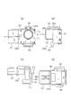
- (a) is a front view of a sensor main body.
- (b) is a right side view of the sensor body.
- (c) is a top view of the sensor body.
- (d) is a rear view of the sensor body. It is AA sectional drawing of Fig.2 (a). It is sectional drawing of a vibrating body.
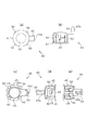
- (a) is a front view of a bezel.
- (b) is a left side view of the bezel.
- (c) is a rear view of a bezel.
- (d) is a top view of the bezel.
- (e) is a bottom view of the bezel. It is an expanded sectional view of the front end part of a bezel.
- the ultrasonic sensor according to the first embodiment will be described.
- the ultrasonic sensor is attached to a bumper of a vehicle and is used to detect an object around the vehicle.
- FIG. 1 is a side view of the ultrasonic sensor of the present embodiment attached to a bumper 100 that is an attachment object.
- FIG. 1 shows only the bumper 100 in cross section.
- the ultrasonic sensor is fixed in the hole 101 of the bumper 100.
- the ultrasonic sensor has a sensor body 200 and an annular bezel 40.
- the ultrasonic sensor is fixed to the bumper 100 by inserting the bezel 40 into the hole 101 from the front side 100 a of the bumper 100 and then inserting the sensor body 200 into the bezel 40 from the back side 100 b of the bumper 100.
- the sensor body 200 of the ultrasonic sensor has a body 30 in which the vibrating body 10 is housed.
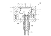
- the vibrating body 10 includes a housing 11, a piezoelectric element 12, a spacer 13, a base 14, and a connection pin 15.
- the housing 11 is made of a conductive material, has a bottomed cylindrical shape, and an internal space 16 is formed therein.
- a piezoelectric element 12 is attached to the inner surface of the bottom 11 a of the housing 11.
- the outer surface of the bottom 11a is a transmission / reception surface 11b.
- Aluminum is used as the conductive material of the housing 11.
- the transmission / reception surface 11b is circular.
- the piezoelectric element 12 is made of piezoelectric ceramics, for example, lead zirconate titanate ceramics, and has electrodes on both front and back surfaces.
- One electrode of the piezoelectric element 12 is electrically connected to one of the pair of connection pins 15 by a lead 17a.
- the other electrode of the piezoelectric element 12 is attached to the bottom 11a of the housing 11 with a conductive adhesive, for example, and connected to the lead 17b through the housing 11, and then electrically connected to the other of the pair of connection pins 15.
- the internal space 16 of the housing 11 is filled with a vibration isolating material, for example, silicone rubber, so that unnecessary vibration transmitted from the transmission / reception surface 11b to the connection pin 15 is suppressed.
- the spacer 13 is disposed between the opening of the housing 11 and the base 14.
- the spacer 13 is an elastic body for suppressing unnecessary vibration generated in the cylindrical portion 11 c of the housing 11 due to vibration of the bottom 11 a of the housing 11 from being transmitted to the base 14 to which the connection pin 15 is fixed.
- it is made of silicone rubber.
- the base 14 is fitted to the outer peripheral surface on the opening side of the housing 11 via a spacer 13 and is fixed to the housing 11.
- the base 14 is made of an insulating material, for example, a synthetic resin such as ABS resin.
- the base 14 is provided with a protection portion 18 for covering the connection pin 15 so as to protrude toward the circuit board 32, and the connection pin 15 is disposed so as to penetrate the protection portion 18.
- the connection pin 15 is insert-molded so that a part of the connection pin 15 is embedded and fixed in the base 14.
- connection pin 15 is made of a conductive material mainly composed of copper, for example, and is composed of a rod having a thickness of 0.5 mm ⁇ , for example.
- the vibrating body 10 is provided with a foamed elastic body 19 made of, for example, foamed silicone.
- the foamed elastic body 19 is for suppressing transmission of vibration to the base 14, and the connection pin 15 is disposed so as to penetrate the foamed elastic body 19.
- the housing 11, the spacer 13, the base 14, and the foamed elastic body 19 are bonded to each other with an adhesive, for example, a silicone-based adhesive, so that the vibration body 10 having an integral structure is configured.
- the vibrating body 10 configured as described above is assembled into a hollow main body 30 made of synthetic resin, with the elastic member 20 covering a part of the side surface and the bottom surface.
- the elastic member 20 is made of an elastic resin, for example, silicone rubber.
- the elastic member 20 has a cylindrical shape, and an enlarged flange portion 21 is formed at the front end which is one end of the length.
- a narrowed bottom 22 is formed at the rear end, which is the other end of the length.
- the outer peripheral surface of the flange portion 21 is formed as a tapered surface whose outer dimension, that is, the diameter gradually decreases toward the end surface of the front end portion. That is, the shape of the flange portion 21 can be said to be tapered. Further, the surface opposite to the front end portion of the flange portion 21 is formed perpendicular to the outer surface of the elastic member 20.
- the diameter of the inner surface of the elastic member 20 is the same as the outer diameter of the housing 11 of the vibrating body 10.
- the vibrating body 10 is accommodated in the cylinder of the elastic member 20, and the outer surface of the vibrating body 10, that is, the outer surface of the housing 11 abuts on the inner surface of the elastic member 20. Further, the bottom surface of the vibrating body 10 abuts on the bottom 22 of the elastic member 20.
- the diameter of the inner surface of the elastic member 20 may be smaller than the outer diameter of the housing 11 of the vibrating body 10. By doing so, the contact force between the elastic member 20 and the vibrating body 10 when the vibrating body 10 is accommodated can be improved.
- the length from the front end portion of the elastic member 20 to the inner surface of the bottom 22 is equal to the length from the transmission / reception surface 11b of the vibrating body 10 to the bottom surface. Therefore, when the vibrating body 10 is accommodated in the elastic member 20, the transmission / reception surface 11 b of the vibrating body 10 and the front end portion of the elastic member 20 are substantially flush with each other.
- the main body 30 is a hollow, substantially rectangular parallelepiped.
- a cylindrical side wall portion 31 having an open upper end is provided on one surface of the main body 30, and the inside of the side wall portion 31 functions as a housing portion 31 a for the vibrating body 10 and the elastic member 20.
- the inner diameter of the side wall portion 31 is equal to the outer diameter of the elastic member 20.
- the outer diameter of the side wall portion 31 is larger than the maximum diameter of the flange portion 21.
- the length from the opening surface of the side wall portion 31 to the inner bottom surface is equal to the length from the surface opposite to the front end portion of the flange portion 21 of the elastic member 20 to the bottom surface.
- the surface opposite to the front end portion of the flange portion 21 of the elastic member 20 abuts on the upper end of the side wall portion 31. Is in contact with the inner bottom surface of the side wall portion 31.
- the inner side surface of the side wall portion 31 is in contact with the outer side surface of the elastic member 20. At this time, a part of the upper end of the side wall portion 31 is covered with the flange portion 21 of the elastic member 20.
- the inner diameter of the side wall 31 may be smaller than the outer diameter of the elastic member 20 and larger than the outer diameter of the housing 11 of the vibrating body 10. By doing so, the contact force between the side wall 31 and the elastic member 20 when the vibrating body 10 and the elastic member 20 are accommodated in the side wall 31 can be improved.
- the main body 30 is provided with a guide 33 for positioning the connection pin 15 with respect to the connection position of the circuit board 32.
- the guide 33 is configured in a plate shape that divides the internal space of the main body 30 into an arrangement space for the vibrating body 10 and an arrangement space for the circuit board 32, and a positioning hole 33 a into which the connection pin 15 and the protection portion 18 are inserted. Is provided.
- the elastic body 20 has an elastic member 20 in contact with the outer peripheral surface thereof, and a foamed elastic body 34 serving as an elastic body that suppresses vibration is disposed below the base 14 and is assembled to the main body 30.
- connection pin 15 is inserted into the positioning hole 33 a of the guide 33, and the tip of the connection pin 15 is inserted into the circuit board 32. Then, the electrical connection between the tip of the connection pin 15 and the circuit board 32 is made by soldering or the like.
- the transmission / reception surface 11 b of the vibrating body 10 is exposed from the side wall portion 31 of the main body 30, and the ultrasonic wave emitted from the vibrating body 10 is transmitted to the outside of the main body 30.
- the foamed elastic body 34 is made of foamed silicone, similar to the foamed elastic body 19 disposed in the housing 11 of the vibrating body 10, and the connection pin 15 and the protection portion 18 penetrate therethrough.
- the foamed elastic body 34 is provided with a cut, and the protection portion 18 can be inserted into the cut.
- the base 14, the elastic member 20, and the foamed elastic body 34 of the vibrating body 10 are bonded and fixed to each other with a silicone-based adhesive.
- a moisture-proof member 35 is filled in a hollow portion where the circuit board 32 is arranged in the main body 30 partitioned by the guide 33.
- a silicone resin or a urethane resin can be applied as the moisture-proof member 35.
- a silicone resin is applied as the moisture-proof member 35.
- an external output terminal 36 for outputting from the circuit board 32 to the outside is provided, and one end side of the external output terminal 36 is exposed from a connector 37 formed on one surface of the main body 30. It is said that.
- a locking portion 38 is provided on the upper surface of the main body 30, and a receiving portion 39 is provided on the bottom surface thereof.
- the locking portion 38 is formed so as to protrude from the upper surface of the main body 30 in the same direction as the side wall portion 31, and is used for fixing to the bezel 40.
- the locking portion 38 has a so-called snap-fit configuration having a rod-like portion 38a and a claw portion 38b.
- the rod-shaped portion 38a is projected from the upper surface of the main body 30 in the same direction as the side wall portion 31, and a claw portion 38b is formed on the side wall portion 31 side at the tip position of the rod-shaped portion 38a.
- the receiving portion 39 has a frame shape provided so as to protrude from the main body 30, and this is also used for fixing to the bezel 40.
- the protruding direction of the side wall 31 is the direction in which the sensor main body 200 is inserted into the bezel 40.
- FIGS. 5A to 5D show the structure of the bezel 40
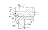
- FIG. 6 shows an enlarged cross section of the front end portion of the bezel 40.
- the bezel 40 is made of a substantially cylindrical member made of synthetic resin or the like, for example.
- the shape and size of the hollow cylindrical portion 40a of the bezel 40 correspond to the shape of the side wall portion 31 in the sensor body 200, and the side wall portion 31 is inserted into the hollow portion.
- An outer flange 41 having an enlarged diameter is formed on the outer peripheral surface of the front end which is one end of the bezel 40 in the axial direction.
- a narrow inner flange 42 is formed on the inner peripheral surface of the front end.
- the outer peripheral surface of the outer flange 41 is formed so that its diameter gradually increases from the end surface of the front end portion. That is, the outer flange 41 can be said to be tapered.
- the inner flange 42 includes an outer surface portion 42a in which the diameter of the inner peripheral surface is constant in the axial direction, and a tapered portion 42b in which the diameter gradually increases from the front end side and the inner peripheral surface is a tapered surface. Is done.
- the angle formed between the inner peripheral surface of the tapered portion 42b and the central axis is equal to the angle formed between the flange portion 21 of the elastic member 20 and the central axis. That is, on the plane passing through the central axis, the inner peripheral surface of the tapered portion 42 b and the outer peripheral surface of the flange portion 21 of the elastic member 20 are formed in parallel.
- concave portions 42c and convex portions 42d are alternately formed in the circumferential direction, thereby forming a rectangular wave-shaped inner peripheral surface.
- the diameter between the opposing convex portions 42 d is formed to be equal to the outer diameter of the flange portion 21 of the elastic member 20. That is, when the side wall portion 31 is inserted into the bezel 40, the convex portion 42 d of the bezel 40 and the flange portion 21 of the elastic member 20 come into contact with each other, and the space between the outer surface portion 42 a of the bezel 40 and the flange portion 21 of the elastic member 20.
- a gap 60 is formed between the concave portion 42 c of the bezel 40 and the flange portion 21 of the elastic member 20.
- the other end of the bezel 40 in the axial direction is provided with a locking portion 43 that protrudes from the cylindrical portion.
- the locking portion 43 is a so-called snap fit, and has a claw portion 43 a formed at the tip, and is engaged with the receiving portion 39 by being inserted into the hole of the receiving portion 39 of the main body 30.
- a locking hole 44 is formed on the upper surface of the bezel 40.
- the locking hole 44 has a rectangular shape when viewed from the front, and is for inserting the claw portion 38b of the locking portion 38 provided in the main body 30 described above. When the claw portion 38 b of the locking portion 38 is inserted into the locking hole 44, the claw portion 38 b is caught on the inner wall of the locking hole 44.
- the left and right sides of the bezel 40 are provided with anti-falling claws 45.
- the removal preventing claw 45 is formed at a position considering the thickness of the bumper 100 and is provided at a position spaced from the end face of the outer flange 41 by the thickness of the bumper 100 or slightly larger than that.
- the removal prevention claw 45 is provided to prevent the bezel 40 from coming off the bumper 100.
- a plurality of, for example, four metal springs 50 are arranged on the bezel 40 at equal intervals.
- the shape of the metal spring 50 is a convex shape toward the radially outer side of the bezel 40. That is, when stress is applied to the metal spring 50 from the radially outer side of the bezel 40, the metal spring 50 is elastically deformed and applies stress to the inner surface of the bezel 40.
- the bezel 40 is inserted into the hole 101 of the bumper 100 from one side of the bumper 100, that is, from the front side 100 a of the bumper 100.
- the removal preventing claw 45 is inserted until it enters the back side 100 b of the bumper 100.
- the opening end of the hole 101 of the bumper 100 and the metal spring 50 come into contact with each other.
- the metal spring 50 is elastically deformed and bent by the opening end of the hole 101 of the bumper 100, and stress is applied to the inner surface of the bezel 40.
- the side wall portion 31 of the main body 30 is inserted into the hollow portion of the bezel 40 from the opposite side of the bumper 100, that is, from the back side 100b of the bumper 100.
- the claw portion 43 a comes into contact with the inner wall of the receiving portion 39 and is elastically deformed and inserted into the receiving portion 39.
- the claw portion 43a and the receiving portion 39 are engaged, and the assembly is completed.
- the claw portion 38b of the locking portion 38 contacts the outer wall surface of the bezel 40, and the rod-like portion 38a is elastically deformed.
- the elastically deformed portion returns to the original state, and the locking portion 38 engages with the locking hole 44.
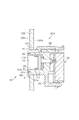
- FIG. 8 shows a cross-sectional view of the ultrasonic sensor thus attached to the bumper 100
- FIG. 9 shows an enlarged cross-sectional view of the vicinity of the front end portion.
- the outer flange 41 of the bezel 40 contacts the bumper 100
- the inner flange 42 of the bezel 40 contacts the upper end of the side wall portion 31 of the main body 30.
- the inner diameter of the outer surface portion 42 a of the inner flange 42 of the bezel 40 is constant, and the inner diameter of the concave portion 42 c of the inner flange 42 of the bezel 40 is larger than the outer diameter of the flange portion 21 of the elastic member 20. Therefore, a gap 60 is generated between the inner flange 42 of the bezel 40 and the flange portion 21 of the elastic member 20. Further, as described above, the angle between the taper portion 42b of the inner flange 42 of the bezel 40 and the central axis is equal to the angle between the flange portion 21 of the elastic member 20 and the central axis.
- the width of the gap 60 formed between the tapered portion 42b and the flange portion 21 of the elastic member 20 is constant in the central axis direction.
- the inner diameter of the convex portion 42d of the inner flange 42 of the bezel 40 is made equal to the outer diameter of the flange portion 21 of the elastic member 20, the convex portion 42d and the flange portion 21 of the elastic member 20 come into contact with each other. It will be.
- FIG. 10 shows a flow path when water is discharged from the front side 100a of the bumper 100 to the ultrasonic sensor attached to the bumper 100 in this way.
- the flow paths are indicated by arrows.
- Water enters the gap 60 between the outer surface portion 42 a and the flange portion 21, and the water pressure causes at least one of deformation of the flange portion 21 and displacement of the entire sensor body 200, and water enters the gap 60.
- the side wall 31 of the main body 30 is pushed toward the inner side of the bumper 100 by water pressure, and the inner flange 42 of the bezel 40 and the upper end of the side wall 31 of the main body 30 are separated from each other. Therefore, water passes between the inner flange 42 of the bezel 40 and the side wall portion 31 of the main body 30 through the gap 60 and flows out of the main body 30.
- the water pressure is applied not only to the side wall portion 31 but also to the elastic member 20.
- the contact force between the elastic member 20 and the vibrating body 10 is increased by the water pressure, and water can be prevented from entering between the vibrating body 10 and the elastic member 20.
- the contact force between the flange portion 21 of the elastic member 20 and the upper end of the side wall portion 31 is also increased, and water can be prevented from entering between the elastic member 20 and the main body 30.
- the housing 11 of the vibrating body 10 is chamfered at the connecting portion between the end portion of the bottom 11a and the end portion of the cylindrical portion 11c to form an arc shape.
- a gap may be formed between the vibrating body 10 and the elastic member 20, and water may enter the main body 30 through the gap.
- the gap 60 between the inner flange 42 of the bezel 40 and the flange portion 21 of the elastic member 20 in the radial direction of the vibrating body 10, the elastic member 20, and the bezel 40 that is, the contact direction, 10 and the gap between the elastic member 20.
- the ultrasonic sensor according to this embodiment has the following effects.
- the flange portion 21 of the elastic member 20 is tapered, when the water pressure is applied to the gap 60, the elastic member 20 is pressed against the vibrating body 10 by the water pressure. Therefore, it is possible to further suppress the intrusion of water between the vibrating body 10 and the elastic member 20.
- a gap 60 can be formed by the concave portions 42c between the convex portions 42d.
- the flange portion 21 of the elastic member 20 is tapered so that the inner dimension increases as the distance from the transmission / reception surface 11b increases, and the inner flange 42 of the bezel 40 increases as the outer dimension increases as the distance from the transmission / reception surface 11b increases. Accordingly, the gap 60 functioning as a water flow path serves as a flow path that guides water to the outside of the main body 30, and thus can more suitably prevent water from entering the main body 30.
- the bezel 40 is attached to the bumper 100 from the front side 100a, and the main body 30 is attached from the back side 100b. In this case, if the main body 30 is removed, the inside of the bezel 40 can be exposed, and even if a foreign object or the like enters the gap 60, it can be easily removed.
- the bezel 40 is integrated with the main body 30 by the tube portion 40a being assembled to the side wall portion 31 of the main body 30, and thereby, rattling with respect to the main body 30 is suppressed in the radial direction.
- the portion of the elastic member 20 facing the bezel 40 has a small dimension in the thickness direction of the sensor, but a uniform gap 60 is formed in the circumferential direction by the coupling of the cylindrical portion 40a and the side wall portion 31. it can.
- the concave portion 42c and the convex portion 42d are alternately provided on the inner flange 42 of the bezel 40 so that the convex portion 42d and the flange portion 21 of the elastic member 20 are in contact with each other. It is not necessary to provide the concave portion 42c and the convex portion 42d.
- the gap 60 is between the bezel 40 and the elastic member 20. May be formed.
- the gap 60 is formed between the bezel 40 and the elastic member 20 by providing the front end portion of the bezel 40 with a concave portion 42c and a convex portion 42d having a rectangular wave shape in the circumferential direction.
- the uneven shape is not limited to this, and any shape may be used as long as the gap 60 is generated between the bezel 40 and the elastic member 20 when the case is assembled to the bezel 40.
- triangular wave irregularities may be provided in the circumferential direction.
- the flange portion 21 of the elastic member 20 and the inner flange 42 of the bezel 40 are both tapered, but only one of the flange portion 21 of the elastic member 20 and the inner flange 42 of the bezel 40 may be tapered. . Further, none of them may be tapered.
- the concave portions 42c and the convex portions 42d are alternately provided on the inner flange 42 of the bezel 40, but the concave portions and the convex portions may be alternately provided on the flange portion 21 of the elastic member 20. Further, the inner flange 42 of the bezel 40 and the flange portion 21 of the elastic member 20 may be provided with recesses and protrusions alternately.
- the ultrasonic sensor is attached to the bumper 100 of the vehicle, but the attachment target of the ultrasonic sensor is not limited to the bumper 100, and may be attached to other parts of the vehicle. Further, the attachment object may be other than the vehicle.
Landscapes
- Engineering & Computer Science (AREA)
- Radar, Positioning & Navigation (AREA)
- Remote Sensing (AREA)
- Physics & Mathematics (AREA)
- Computer Networks & Wireless Communication (AREA)
- General Physics & Mathematics (AREA)
- Mechanical Engineering (AREA)
- Acoustics & Sound (AREA)
- Measurement Of Velocity Or Position Using Acoustic Or Ultrasonic Waves (AREA)
Abstract
取付対象物貫通した状態で取り付けられる超音波センサであって、超音波を送受信する送受信面を有する振動体と、送受信面からその厚み方向に延びる振動体の外側面を囲み、その外側面に内側面が当接する筒状の弾性部材と、振動体及び弾性部材を、送受信面の側の一部の突出部分を除いて収容する収容部を有する本体と、弾性部材の突出部分を囲むようにして設けられ、取付対象物の表側に当接した状態で本体に組み付けられる環状体と、を備え、弾性部材の突出部分の外側面と、その外側面に対向する環状体の内側面との間に隙間が設けられる。これにより、本体への水の浸入を抑制することが可能な超音波センサが提供される。
Description
本出願は、2015年12月25日に出願された日本出願2015‐254447号に基づく優先権を主張し、この日本出願に記載されたすべての記載内容を援用するものである。
本発明は、超音波センサに関する。
従来、車両のバンパ等に設けられた超音波センサにより車両と車両周囲の物体との距離を検出し、車両と物体との衝突を回避する制御装置が公知である。
特開2013-107493号公報は、上記のような超音波センサを開示している。この超音波センサは、超音波を送受信する送受信面を有する振動体と、振動体の外側面を囲む筒状の弾性部材と、振動体及び弾性部材を収容する収容部を備える本体部と、弾性部材を囲むようにして設けられ、取付対象物の表側に当接した状態で前記本体部に組み付けられる環状体と、を備え、取付対象物を貫通した状態でその取付対象物に取り付けられる。
特許文献1に記載の超音波センサが取り付けられた車両は、高圧洗浄機を用いた洗車が行われる場合がある。このとき、水圧により収容部と弾性部材との間や、弾性部材と振動体と間を介して本体部の内部へと水が浸入することがある。このとき、本体部の内部の水圧が高まり、水圧により振動体が収容部の外部へと押し出されるおそれがある。
本発明は上記課題を解決するためになされたものであり、その主たる目的は、本体部への水の浸入を抑制する超音波センサを提供することにある。
本発明は、取付対象物に、該取付対象物を貫通した状態で取り付けられる超音波センサであって、超音波を送受信する送受信面を有する振動体と、送受信面から厚み方向に延びる振動体の外側面を囲み、その外側面に内側面が当接する筒状の弾性部材と、振動体及び弾性部材を、送受信面の側の一部の突出部分を除いて収容する有底の収容部を有する本体部と、弾性部材の突出部分を囲むようにして設けられ、取付対象物の表側に当接した状態で本体部に組み付けられる環状体と、を備え、弾性部材の突出部分の外側面と、その外側面に対向する環状体の内側面との間に隙間が設けられる。
上記構成では、取付対象物の表側から送受信面に対して放水が行われた場合に、水は弾性部材と環状体との間の隙間へ浸入し、その隙間を通って本体部の外部へと流出する。加えて、水圧が弾性部材に加わることにより弾性部材が変形し、弾性部材と振動体との当接力が増加するため、弾性部材と振動体との間へ水が浸入しづらくなる。したがって、取付対象物の表側から送受信面に対して放水が行われた場合に、本体部への水の浸入を抑制することができる。
以下、本発明の実施形態について図に基づいて説明する。なお、以下の各実施形態相互において、互いに同一もしくは均等である部分には、図中、同一符号を付してある。
第1実施形態にかかる超音波センサについて説明する。超音波センサは、例えば、車両のバンパに取り付けられ、車両周囲の物体の検出に用いられる。
図1は、取付対象物であるバンパ100に取り付けた本実施形態の超音波センサの側面図である。なお、図1はバンパ100のみ断面を示す。
超音波センサは、バンパ100の穴101内に固定される。超音波センサは、センサ本体200と、環状のベゼル40とを有している。バンパ100の表側100aからベゼル40を穴101内へ挿入したのち、バンパ100の裏側100bからセンサ本体200をベゼル40内に挿入することで、超音波センサはバンパ100に固定される。
超音波センサのセンサ本体200の構造を、図2(a)~図4を用いて説明する。図2(a)―2(d)、図3に示すようにセンサ本体200は、振動体10が収納された本体30を有する。図4に示すように、振動体10は、ハウジング11、圧電素子12と、スペーサ13、ベース14および接続ピン15を有している。
ハウジング11は、導電性材料で構成され、有底円筒状であり、その内部に内部空間16が形成されている。ハウジング11の底11aの内面に圧電素子12が貼着されている。この底11aの外側表面が送受信面11bとなっている。ハウジング11の導電性材料としてアルミニウムを用いている。送受信面11bは円形状である。
圧電素子12は、圧電セラミックス、例えばチタン酸ジルコン酸鉛系セラミックスで構成され、その表裏両面に電極を備えている。圧電素子12の一方の電極は、リード17aによって一対の接続ピン15の一方に電気的に接続されている。圧電素子12の他方の電極は、ハウジング11の底11aに例えば導電性接着剤により貼着され、ハウジング11を介してリード17bに接続されたのち、一対の接続ピン15の他方に電気的に接続されている。なお、ハウジング11の内部空間16には、防振材、例えば、シリコーンゴムが充填されており、送受信面11bから接続ピン15に伝達される不要振動が抑制されている。
スペーサ13は、ハウジング11の開口部とベース14との間に配置されている。スペーサ13は、ハウジング11の底11aの振動に伴ってハウジング11の筒部11cに生じる不要振動が、接続ピン15の固定されているベース14に伝達されるのを抑制するための弾性体であり、例えばシリコーンゴムから構成されている。
ベース14は、ハウジング11の開口部側の外周面にスペーサ13を介して嵌め込まれ、ハウジング11に固定されている。ベース14は絶縁材料、例えばABS樹脂等の合成樹脂で構成されている。ベース14には、接続ピン15を被覆するための保護部18が回路基板32側に突出するように設けられ、接続ピン15が保護部18を貫通するように配置されている。ベース14を成形する際に、接続ピン15をインサート成形することで、接続ピン15の一部がベース14に埋設固定されるようにしている。
接続ピン15は、例えば銅を主成分とする導電性材料からなり、例えば太さ0.5mmφの棒で構成される。
さらに、振動体10には、例えば発泡シリコーン等で構成された発泡弾性体19が備えられている。この発泡弾性体19は、ベース14への振動の伝達を抑制するためのもので、接続ピン15は発泡弾性体19も貫通するように配置されている。
そして、ハウジング11、スペーサ13、ベース14、発泡弾性体19が、それぞれ接着剤、例えばシリコーン系接着剤で接着されることで、一体構造とされた振動体10が構成されている。このように構成された振動体10は、弾性部材20に側面、及び底面の一部が覆われて、合成樹脂からなる中空の本体30内に組み付けられる。
弾性部材20は、弾性を有する樹脂、例えばシリコーンゴムにより形成されている。弾性部材20は円筒状であり、その長さの一端である前端には、拡径されたフランジ部21が形成されている。一方、その長さの他端である後端には、狭径された底22が形成されている。フランジ部21の外周面は、前端部の端面に向けて徐々に外寸法、すなわち直径が小さくなるテーパ面として形成されている。すなわち、フランジ部21の形状はテーパ状といえる。また、フランジ部21の前端部に対して反対側の面は、弾性部材20の外側面に対して垂直に形成されている。
弾性部材20の内側面の直径は、振動体10のハウジング11の外径と同径である。弾性部材20の筒内には振動体10が収容され、弾性部材20の内側面に振動体10の外側面、すなわち、ハウジング11の外側面が当接する。また、弾性部材20の底22には、振動体10の底面が当接する。なお、弾性部材20の内側面の直径を、振動体10のハウジング11の外径よりも小さくしてもよい。こうすることにより、振動体10を収容した際の、弾性部材20と振動体10との当接力を向上させることができる。
弾性部材20の前端部から底22の内面までの長さは、振動体10の送受信面11bから底面までの長さと等しい。したがって、振動体10が弾性部材20に収容された際に、振動体10の送受信面11bと弾性部材20の前端部は略面一となる。
本体30は、中空状の略長方体である。本体30の一面には、上端が開口した円筒形の側壁部31が設けられており、その側壁部31の内部が、振動体10及び弾性部材20の収容部31aとして機能する。側壁部31の内径は、弾性部材20の外径と等しい。側壁部31の外径は、フランジ部21の最大径よりも大きい。側壁部31の開口面から内側底面までの長さは、弾性部材20のフランジ部21の前端部に対して反対側の面から底面までの長さと等しい。したがって、振動体10及び弾性部材20が側壁部31に収容された際に、弾性部材20のフランジ部21の前端部に対して反対側の面が側壁部31の上端に当接し、弾性部材20の底面が、側壁部31の内側底面に当接する。
側壁部31の内側面は、弾性部材20の外側面に当接する。このとき、側壁部31の上端の一部が、弾性部材20のフランジ部21により覆われることとなる。なお、側壁部31の内径を、弾性部材20の外径よりも小さく、且つ、振動体10のハウジング11の外径よりも大きいものとしてもよい。こうすることにより、振動体10及び弾性部材20を側壁部31へ収容した際の、側壁部31と弾性部材20との当接力を向上させることができる。
本体30には、回路基板32の接続位置に対して接続ピン15を位置決めするためのガイド33が設けられている。このガイド33は、本体30の内部空間を振動体10の配置空間と回路基板32の配置空間とに区画する板状に構成され、接続ピン15および保護部18が挿入される位置決め用穴33aが備えられている。
振動体10は、その外周面に弾性部材20が当接させられると共に、ベース14の下側に振動を抑制する弾性体となる発泡弾性体34が配置されて本体30に組み付けられている。
このように振動体10を本体30に組み付けた状態において、接続ピン15がガイド33の位置決め用穴33aに挿入され、接続ピン15の先端部が回路基板32に挿入されている。そして、接続ピン15の先端部と回路基板32との電気的な接続がはんだ付け等によって為されている。
本体30の側壁部31からは、振動体10の送受信面11bが露出しており、振動体10が発する超音波が本体30の外部に伝えられるような構成とされている。
発泡弾性体34は、振動体10のハウジング11内に配置された発泡弾性体19と同様、発泡シリコーンからなり、接続ピン15及び保護部18が貫通している。発泡弾性体34には切り込みが設けられ、その切り込み内に保護部18が挿入可能な構成としている。なお、振動体10のベース14、弾性部材20、及び発泡弾性体34は、シリコーン系接着剤により相互に接着固定されている。
また、ガイド33により区画された本体30のうち回路基板32が配置される中空部には、防湿性部材35が充填されている。防湿性部材35としては、例えばシリコーン樹脂やウレタン樹脂を適用することができる。本実施形態においてはシリコーン樹脂を適用している。なお、図3に示すように、回路基板32から外部に出力するための外部出力端子36が備えられ、本体30の一面に形成されたコネクタ37から外部出力端子36の一端側が露出させられた構成とされている。
さらに、本体30の上面には係止部38が設けられており、その底面には受止部39が設けられている。係止部38は、本体30の上面から側壁部31と同方向に突出するように形成されており、ベゼル40との固定のために用いられる。具体的には、係止部38は、棒状部38aおよび爪部38bを有する、いわゆるスナップフィット構成とされている。棒状部38aが本体30の上面から側壁部31と同方向に突出させられ、この棒状部38aの先端位置における側壁部31側に爪部38bが形成されている。受止部39は、本体30から突出するように設けられた枠状をしており、これもベゼル40との固定のために用いられる。
このように構成されるセンサ本体200のうち、振動体10および側壁部31の部分、つまり本体30のうち円筒形状に突出する部分がベゼル40に挿入される。このため、側壁部31の突出方向がベゼル40へのセンサ本体200の挿入方向となる。
図5(a)~(d)にベゼル40の構造を示し、図6に、ベゼル40の前端部の拡大断面を示す。ベゼル40は、例えば合成樹脂等によって構成された略円筒状の部材によって構成されている。このベゼル40の中空の筒部40aの形状およびサイズは、センサ本体200における側壁部31の形状と対応したものとなっており、この中空部内に側壁部31が挿入される。
ベゼル40の軸方向の一端である前端部の外周面には、拡径した外側フランジ41が形成されている。その前端部の内周面には、狭径した内側フランジ42が形成されている。外側フランジ41の外周面は、前端部の端面から徐々に径が大きくなるように形成されている。すなわち、外側フランジ41の形状はテーパ状といえる。内側フランジ42は、内周面の径が軸方向について一定である外面部42aと、前端部側から径が徐々に大きくなり内周面がテーパ面とされているテーパ部42bとを含んで構成される。テーパ部42bの内周面と中心軸とのなす角度は、弾性部材20のフランジ部21と中心軸とのなす角度と等しくされている。すなわち、中心軸を通る平面上において、テーパ部42bの内周面と、弾性部材20のフランジ部21の外周面とは平行となるように形成されている。
テーパ部42bの内周面には、周方向ついて凹部42cと凸部42dが交互に形成されており、矩形波状の内周面を構成している。対向する凸部42d間の径は、弾性部材20のフランジ部21の外径と等しく形成されている。すなわち、ベゼル40に側壁部31を挿入した際に、ベゼル40の凸部42dと弾性部材20のフランジ部21とが当接し、ベゼル40の外面部42aと弾性部材20のフランジ部21との間、及びベゼル40の凹部42cと弾性部材20のフランジ部21との間に隙間60が形成される。
ベゼル40の軸方向の他端部には、円筒状部分から突出させられた係止部43が設けられている。係止部43は、いわゆるスナップフィットであり、先端に爪部43aが形成されており、本体30の受止部39の穴内に挿入されることで、受止部39と係合される。
ベゼル40の上面には、係止穴44が形成されている。係止穴44は、正面から見ると四角形状を為した穴であり、上述した本体30に備えられた係止部38の爪部38bを挿入するためのものである。係止部38の爪部38bが係止穴44に挿入されると、係止穴44の内壁に爪部38bが引っ掛かるようになっている。
また、ベゼル40の外周面のうちベゼル40の左右両側の位置に抜け防止爪45が備えられている。抜け防止爪45は、バンパ100の厚み分を考慮した位置に形成されており、外側フランジ41の端面からバンパ100の厚み分、もしくはそれより若干大きな間隔を空けた位置に備えられている。この抜け防止爪45は、ベゼル40のバンパ100からの抜けを防止するために設けられている。ベゼル40をバンパ100に取り付けた後、ベゼル40に本体30の側壁部31を挿入するに当たり、ベゼル40がバンパ100から抜ける方向に力が加えられることになる。このため、ベゼル40をバンパ100に挿入すると、抜け防止爪45がバンパ100の端面に引っ掛かり、ベゼル40のバンパ100からの抜けが防止できるようになっている。
さらに、ベゼル40には、等間隔に複数、例えば4つの金属バネ50が配置されている。この金属バネ50の形状は、ベゼル40の径方向外側に向けて凸の形状である。すなわち、ベゼル40の径方向外側から金属バネ50に応力が加わると、金属バネ50は弾性変形して、ベゼル40の内側面へ応力を加える。
次に、超音波センサのバンパ100への取り付け方法について説明する。図7に示すように、まず、ベゼル40をバンパ100の一方、つまりバンパ100の表側100aからバンパ100の穴101に挿入する。このとき、抜け防止爪45がバンパ100の裏側100bに入り込むまで挿入する。これにより、バンパ100の穴101の開口端と金属バネ50が接触する。ベゼル40をバンパ100の穴101に挿入すると、バンパ100の穴101の開口端によって金属バネ50が弾性変形させられて撓み、ベゼル40の内側面へ応力を加える。
この後、バンパ100の反対側、つまりバンパ100の裏側100bからベゼル40の中空部内に本体30の側壁部31を挿入する。このとき、係止部43の先端部が受止部39の穴内に入り込み、爪部43aが受止部39の内壁と接して弾性変形させられ、受止部39内に挿入されると、その後、弾性変形した部分が元に戻ることで爪部43aと受止部39とが係合し、組み付けが完了する。また、係止部38の爪部38bがベゼル40の外壁面と接し、棒状部38aが弾性変形する。そして、爪部38bが係止穴44内に入り込むことで、弾性変形した部分が元に戻り、係止部38が係止穴44と係合する。
このようにバンパ100に取り付けられた超音波センサの断面図を、図8に示し、前端部近傍の拡大断面図を図9に示す。ベゼル40の外側フランジ41はバンパ100に当接し、ベゼル40の内側フランジ42は、本体30の側壁部31の上端に当接する。
このとき、ベゼル40の内側フランジ42の外面部42aについて、内径を一定としており、ベゼル40の内側フランジ42の凹部42cについて、内径を弾性部材20のフランジ部21の外径よりも大きくしているため、ベゼル40の内側フランジ42と弾性部材20のフランジ部21との間には、隙間60が生ずる。また、上述した通り、ベゼル40の内側フランジ42のテーパ部42bと中心軸とのなす角度と、弾性部材20のフランジ部21と中心軸とのなす角度とを等しくしているため、ベゼル40のテーパ部42bと弾性部材20のフランジ部21との間に形成される隙間60の幅は、中心軸線方向で一定である。加えて、ベゼル40の内側フランジ42の凸部42dについて、内径を弾性部材20のフランジ部21の外径と等しくしているため、その凸部42dと弾性部材20のフランジ部21とは当接することとなる。
このようにしてバンパ100に取り付けられた超音波センサに対して、バンパ100の表側100aから放水が行われた場合の流路を、図10に示す。図10において、流路を矢印で示している。水は外面部42aとフランジ部21の間の隙間60へと浸入し、水圧により、フランジ部21の変形及びセンサ本体200全体の位置ずれの少なくとも一方が生じ、水は隙間60へと浸入する。このとき、水圧により本体30の側壁部31がバンパ100の内側方向へと押され、ベゼル40の内側フランジ42と本体30の側壁部31の上端とが離間する。したがって、水は隙間60を介してベゼル40の内側フランジ42と本体30の側壁部31との間を通過し、本体30の外部へと流出することとなる。
加えて、水圧は側壁部31のみならず、弾性部材20にも加わる。このとき、水圧により弾性部材20と振動体10との当接力が増加し、振動体10と弾性部材20との間への水の浸入を防ぐことができる。また、弾性部材20のフランジ部21と側壁部31の上端との当接力も増加し、弾性部材20と本体30との間への水の浸入を防ぐことができる。
ところで、一般的に、振動体10のハウジング11について底11aの端部と筒部11cの端部との接続部分に面取りがなされ、円弧状に形成される。この場合、振動体10を弾性部材20に収容すれば、振動体10と弾性部材20との間に隙間が生じ、その隙間を介して本体30内へ水が浸入する場合がある。これを防ぐために、振動体10、弾性部材20、及びベゼル40の径方向、すなわち当接方向において、ベゼル40の内側フランジ42と弾性部材20のフランジ部21との間の隙間60を、振動体10と弾性部材20との間の隙間よりも広くする。こうすることで、超音波センサに対して放水が行われた場合に、水が振動体10と弾性部材20との間の隙間よりも、弾性部材20とベゼル40との間の隙間60へと優先的に浸入する。このとき、弾性部材20と振動体10との当接力が増加し、弾性部材20と振動体10との間への水の浸入を抑制することができる。
上記構成により、本実施形態に係る超音波センサは、以下の効果を奏する。
・取付対象物であるバンパ100の表側100aから送受信面11bに対して放水が行われた場合に、水は弾性部材20とベゼル40との間の隙間60へ浸入し、その隙間60を通ってバンパ100の裏側100bへと流出する。加えて、水圧が弾性部材20に加わることにより弾性部材20が変形し、弾性部材20と振動体10との当接力が増加するため、弾性部材20と振動体10との間へ水が浸入しづらくなる。したがって、バンパ100の表側100aから送受信面11bに対して放水が行われた場合に、本体30への水の浸入を抑制することができる。
・弾性部材20のフランジ部21をテーパ状としたため、隙間60へ水圧が加わった際に、その水圧により、弾性部材20は振動体10へ押し付けられる。ゆえに、振動体10と弾性部材20との間への水の浸入をより抑制することができる。
・ベゼル40の外側フランジ41に設けられた凸部42dと、弾性部材20のフランジ部21とが当接するようにしているため、ベゼル40に本体30を取り付けた際の歪みなどを抑制しつつ、凸部42d間の凹部42cにより隙間60を構成することができる。
・弾性部材20のフランジ部21を送受信面11bから離れるほど内寸法が大きくなるテーパ状とし、ベゼル40の内側フランジ42を送受信面11bから離れるほど外寸法が大きくなるテーパとしている。これにより、水の流路として機能する隙間60は、水を本体30の外部へと誘導する流路となるため、より好適に本体30への水の浸入を抑制することができる。
・バンパ100に対して、ベゼル40が表側100aから取り付けられ、本体30が裏側100bから取り付けられる構成となっている。この場合、本体30を取り外せば、ベゼル40の内側を露出させることができ、仮に隙間60に異物等が入り込んだとしても容易に除去することができる。
・ベゼル40は、その筒部40aが本体30の側壁部31に組み付けられることで、本体30に一体化されており、これにより径方向について本体30に対するがたつきが抑制されている。弾性部材20の先端部とベゼル40との対向部分は、センサの厚み方向において僅かな寸法となっているが、筒部40aと側壁部31との結合により、周方向に均等な隙間60を形成できる。
・超音波センサに対して放水などが行われた際に、水圧により本体30とベゼル40との間に位置ずれが生じ、水の流路が形成されるようにしているため、水圧等が加わっていない場合において、その流路への塵や埃等の侵入を抑制することができる。
<変形例>
・実施形態では、ベゼル40の内側フランジ42に凹部42c及び凸部42dを交互に設け、凸部42dと弾性部材20のフランジ部21とが当接するようにしているが、ベゼル40の内側フランジ42に凹部42c及び凸部42dを設けなくてもよい。この場合、ベゼル40の内側フランジ42の内径を弾性部材20のフランジ部21の外径よりも大きくし、ベゼル40にケースを組みつけた際に、ベゼル40と弾性部材20との間に隙間60が形成されるようにすればよい。
・実施形態では、ベゼル40の内側フランジ42に凹部42c及び凸部42dを交互に設け、凸部42dと弾性部材20のフランジ部21とが当接するようにしているが、ベゼル40の内側フランジ42に凹部42c及び凸部42dを設けなくてもよい。この場合、ベゼル40の内側フランジ42の内径を弾性部材20のフランジ部21の外径よりも大きくし、ベゼル40にケースを組みつけた際に、ベゼル40と弾性部材20との間に隙間60が形成されるようにすればよい。
・実施形態では、ベゼル40の前端部に、周方向について矩形波状の凹部42c及び凸部42dを設けることにより、ベゼル40と弾性部材20との間に隙間60を形成している。この点、凹凸の形状はこれに限られず、ベゼル40にケースを組みつけた際に、ベゼル40と弾性部材20との間に隙間60が生じる形状であればよい。例えば、周方向について三角波状の凹凸を設けてもよい。
・実施形態では、弾性部材20のフランジ部21及びベゼル40の内側フランジ42を共にテーパ状としたが、弾性部材20のフランジ部21とベゼル40の内側フランジ42の一方のみをテーパ状としてもよい。また、いずれもテーパ状としないものとしてもよい。
・実施形態では、ベゼル40の内側フランジ42に凹部42c及び凸部42dを交互に設けるものとしたが、弾性部材20のフランジ部21に凹部及び凸部を交互に設けるものとしてもよい。また、ベゼル40の内側フランジ42及び弾性部材20のフランジ部21のいずれにも凹部及び凸部を交互に設けるものとしてもよい。
・実施形態では、超音波センサが車両のバンパ100に取り付けられるものとしたが、超音波センサの取付対象はバンパ100に限られず、車両のその他の部位に取り付けられてもよい。また、取付対象物は車両以外としてもよい。
Claims (8)
- 取付対象物(100)に、該取付対象物を貫通した状態で取り付けられる超音波センサであって、
超音波を送受信する送受信面(11b)を有する振動体(10)と、
前記送受信面から、その厚み方向に延びる前記振動体の外側面を囲み、その外側面に内側面が当接する筒状の弾性部材(20)と、
前記振動体及び前記弾性部材を、前記送受信面の側の一部の突出部分を除いて収容する有底の収容部(31a)を有する本体部(30)と、
前記弾性部材の突出部分を囲むようにして設けられ、前記取付対象物の表側(100a)に当接した状態で前記本体部に組み付けられる環状体(40)と、を備え、
前記弾性部材の突出部分の外側面と、その外側面に対向する前記環状体の内側面との間に隙間(60)が設けられる、超音波センサ。 - 前記振動体、前記弾性部材、及び前記環状体の当接方向において、前記隙間は、前記弾性部材の突出部分の内側面とその内側面に対向する前記振動体の外側面との間の隙間よりも広く形成されている、請求項1に記載の超音波センサ。
- 前記取付対象物の前記表側と裏側(100b)とが、前記隙間を介して連通する、請求項1又は2に記載の超音波センサ。
- 前記弾性部材の突出部分の外側面は、前記送受信面から離れるほど外寸法が大きくなるテーパ面を有する、請求項1~3のいずれか1項に記載の超音波センサ。
- 前記環状体の内側面は、前記送受信面から離れるほど内寸法が大きくなるテーパ面を有する、請求項4に記載の超音波センサ。
- 前記取付対象物に対して、前記環状体が表側から取り付けられ、前記本体部が裏側から取り付けられる、請求項1~5のいずれか1項に記載の超音波センサ。
- 前記弾性部材の突出部分の外側面と前記環状体の内側面とのいずれかには、周方向に複数の凹部(42c)及び凸部(42d)が形成されており、その凹部及び凸部により前記隙間が設けられる、請求項1~6のいずれか1項に記載の超音波センサ。
- 前記本体部は、前記収容部を形成する側壁部(31)を有し、
前記環状体は、前記側壁部の外側に組み付けられる筒部を有する、請求項1~7のいずれか1項に記載の超音波センサ。
Priority Applications (4)
| Application Number | Priority Date | Filing Date | Title |
|---|---|---|---|
| DE112016005983.3T DE112016005983B4 (de) | 2015-12-25 | 2016-12-21 | Ultraschallsensor |
| CN201680075252.8A CN108431627B (zh) | 2015-12-25 | 2016-12-21 | 超声波传感器 |
| US16/064,681 US11156703B2 (en) | 2015-12-25 | 2016-12-21 | Ultrasonic sensor |
| RU2018127140A RU2696405C1 (ru) | 2015-12-25 | 2016-12-21 | Ультразвуковой датчик |
Applications Claiming Priority (2)
| Application Number | Priority Date | Filing Date | Title |
|---|---|---|---|
| JP2015254447A JP6443322B2 (ja) | 2015-12-25 | 2015-12-25 | 超音波センサ |
| JP2015-254447 | 2015-12-25 |
Publications (1)
| Publication Number | Publication Date |
|---|---|
| WO2017110884A1 true WO2017110884A1 (ja) | 2017-06-29 |
Family
ID=59089457
Family Applications (1)
| Application Number | Title | Priority Date | Filing Date |
|---|---|---|---|
| PCT/JP2016/088130 Ceased WO2017110884A1 (ja) | 2015-12-25 | 2016-12-21 | 超音波センサ |
Country Status (6)
| Country | Link |
|---|---|
| US (1) | US11156703B2 (ja) |
| JP (1) | JP6443322B2 (ja) |
| CN (1) | CN108431627B (ja) |
| DE (1) | DE112016005983B4 (ja) |
| RU (1) | RU2696405C1 (ja) |
| WO (1) | WO2017110884A1 (ja) |
Families Citing this family (10)
| Publication number | Priority date | Publication date | Assignee | Title |
|---|---|---|---|---|
| DE102015212599B3 (de) * | 2015-07-06 | 2016-06-23 | Robert Bosch Gmbh | Ultraschallsensorvorrichtung zur Anordnung an einem Verkleidungsbauteil eines Fahrzeugs |
| JP6443322B2 (ja) | 2015-12-25 | 2018-12-26 | 株式会社デンソー | 超音波センサ |
| US20200142060A1 (en) * | 2017-05-16 | 2020-05-07 | Mitsubishi Electric Corporation | Ultrasonic sensor device and obstacle detection device |
| JP6870594B2 (ja) | 2017-11-28 | 2021-05-12 | 株式会社デンソー | 超音波センサ |
| JP7024662B2 (ja) * | 2018-08-24 | 2022-02-24 | 株式会社デンソー | リテーナ部材 |
| DE102018127418A1 (de) * | 2018-11-02 | 2020-05-07 | Brose Fahrzeugteile Se & Co. Kommanditgesellschaft, Bamberg | Traganordnung für eine Steuerung eines Kraftfahrzeugs |
| JP7230453B2 (ja) * | 2018-11-20 | 2023-03-01 | トヨタ自動車株式会社 | 車両用センサの搭載構造 |
| CN110673149A (zh) * | 2019-10-22 | 2020-01-10 | 江苏理工学院 | 一种基于电动汽车辅助驾驶用雷达测距报警装置 |
| DE102020002912B4 (de) | 2020-05-14 | 2022-01-27 | Daimler Ag | Sensoranordnung zum Selbstpositionieren eines Sensors in einem Bauteil eines Fahrzeugs und Verfahren zur Montage des Sensors |
| US11884223B2 (en) * | 2021-12-01 | 2024-01-30 | Google Llc | Ground vehicle bumper system |
Citations (4)
| Publication number | Priority date | Publication date | Assignee | Title |
|---|---|---|---|---|
| JP2007284035A (ja) * | 2006-03-23 | 2007-11-01 | Denso Corp | 超音波センサ |
| US20130009528A1 (en) * | 2011-01-28 | 2013-01-10 | Zhitao Li | Reversing Radar Sensor Component |
| JP2014098579A (ja) * | 2012-11-13 | 2014-05-29 | Panasonic Corp | 超音波センサ |
| EP2869081A1 (en) * | 2013-11-04 | 2015-05-06 | Tung Thih Electronic Co., Ltd. | Parking sensor device |
Family Cites Families (16)
| Publication number | Priority date | Publication date | Assignee | Title |
|---|---|---|---|---|
| US3850326A (en) * | 1973-01-11 | 1974-11-26 | Medical Plastics Pty Ltd | Safety closure |
| US20080161989A1 (en) * | 1995-06-07 | 2008-07-03 | Automotive Technologies International, Inc. | Vehicle Diagnostic or Prognostic Message Transmission Systems and Methods |
| US8060282B2 (en) * | 1995-06-07 | 2011-11-15 | Automotive Technologies International, Inc. | Vehicle component control methods and systems based on vehicle stability |
| US20080046149A1 (en) * | 1995-06-07 | 2008-02-21 | Automotive Technologies International, Inc. | Vehicle Component Control Methods and Systems Based on Vehicle Stability |
| US5729077A (en) * | 1995-12-15 | 1998-03-17 | The Penn State Research Foundation | Metal-electroactive ceramic composite transducer |
| CN1779482B (zh) * | 2004-11-26 | 2010-04-21 | 中国船舶重工集团公司第七一五研究所 | 水声超宽带组合声阵与发射的方法及其装置 |
| JP4438667B2 (ja) | 2005-03-29 | 2010-03-24 | 株式会社デンソー | 超音波センサ及び超音波振動子 |
| CN2802519Y (zh) * | 2005-07-06 | 2006-08-02 | 中国科学院声学研究所 | 一种小型压电陶瓷水听器 |
| HK1117990A2 (zh) * | 2007-10-25 | 2009-01-23 | The Sunrider Corporation | 安全密封的貯存室蓋 |
| DE102009046972A1 (de) * | 2009-11-23 | 2011-05-26 | Robert Bosch Gmbh | Ultraschallsensor |
| CN102156277A (zh) * | 2011-01-28 | 2011-08-17 | 广东铁将军防盗设备有限公司 | 倒车雷达传感器组件 |
| JP5804907B2 (ja) | 2011-11-21 | 2015-11-04 | 日本セラミック株式会社 | 超音波送受信器 |
| EP2799900A4 (en) * | 2011-12-28 | 2015-10-28 | Panasonic Ip Man Co Ltd | ULTRASOUND SENSOR |
| DE102012002760A1 (de) * | 2012-02-11 | 2013-08-14 | Volkswagen Aktiengesellschaft | Anordnung an einem Bauteil eines Kraftfahrzeuges |
| CN104198593B (zh) * | 2014-08-26 | 2016-06-29 | 中国船舶重工集团公司第七一五研究所 | 一种高静水压低频校准腔体及测试方法 |
| JP6443322B2 (ja) | 2015-12-25 | 2018-12-26 | 株式会社デンソー | 超音波センサ |
-
2015
- 2015-12-25 JP JP2015254447A patent/JP6443322B2/ja active Active
-
2016
- 2016-12-21 RU RU2018127140A patent/RU2696405C1/ru active
- 2016-12-21 US US16/064,681 patent/US11156703B2/en active Active
- 2016-12-21 CN CN201680075252.8A patent/CN108431627B/zh active Active
- 2016-12-21 WO PCT/JP2016/088130 patent/WO2017110884A1/ja not_active Ceased
- 2016-12-21 DE DE112016005983.3T patent/DE112016005983B4/de active Active
Patent Citations (4)
| Publication number | Priority date | Publication date | Assignee | Title |
|---|---|---|---|---|
| JP2007284035A (ja) * | 2006-03-23 | 2007-11-01 | Denso Corp | 超音波センサ |
| US20130009528A1 (en) * | 2011-01-28 | 2013-01-10 | Zhitao Li | Reversing Radar Sensor Component |
| JP2014098579A (ja) * | 2012-11-13 | 2014-05-29 | Panasonic Corp | 超音波センサ |
| EP2869081A1 (en) * | 2013-11-04 | 2015-05-06 | Tung Thih Electronic Co., Ltd. | Parking sensor device |
Also Published As
| Publication number | Publication date |
|---|---|
| CN108431627B (zh) | 2021-12-14 |
| US11156703B2 (en) | 2021-10-26 |
| DE112016005983B4 (de) | 2021-04-22 |
| RU2696405C1 (ru) | 2019-08-01 |
| DE112016005983T5 (de) | 2018-09-20 |
| JP2017116478A (ja) | 2017-06-29 |
| US20190004161A1 (en) | 2019-01-03 |
| CN108431627A (zh) | 2018-08-21 |
| JP6443322B2 (ja) | 2018-12-26 |
Similar Documents
| Publication | Publication Date | Title |
|---|---|---|
| JP6443322B2 (ja) | 超音波センサ | |
| JP4893322B2 (ja) | 超音波センサ | |
| JP4742924B2 (ja) | 超音波センサ | |
| US11474239B2 (en) | Ultrasonic wave sensor | |
| JP4720587B2 (ja) | 超音波センサ | |
| CN1841087B (zh) | 超声传感器 | |
| US10288730B2 (en) | Ultrasonic sensor | |
| US20090223296A1 (en) | Attachment structure for ultrasonic sensor | |
| JP4742923B2 (ja) | 超音波センサ | |
| CN107367732B (zh) | 超声波传感器 | |
| JP5195572B2 (ja) | 超音波センサ | |
| JP5984082B2 (ja) | 超音波センサ | |
| JP5673217B2 (ja) | 超音波センサ | |
| US7628076B2 (en) | Ultrasound sensor | |
| JP4640223B2 (ja) | 超音波センサ | |
| WO2018164153A1 (ja) | 超音波センサ | |
| KR20150058895A (ko) | 차량용 초음파 센서 | |
| KR20180055172A (ko) | 차량용 감지센서 | |
| KR20160013683A (ko) | 차량용 감지센서 | |
| US11049483B2 (en) | Acoustic sensor having a housing and a diaphragm element situated on this housing | |
| KR102326056B1 (ko) | 차량용 감지센서 | |
| KR20240152383A (ko) | 차량용 초음파 센서 | |
| WO2019131663A1 (ja) | 液面検出装置 | |
| JP2019117183A (ja) | 液面検出装置 | |
| KR20160011450A (ko) | 차량용 감지센서 |
Legal Events
| Date | Code | Title | Description |
|---|---|---|---|
| 121 | Ep: the epo has been informed by wipo that ep was designated in this application |
Ref document number: 16878771 Country of ref document: EP Kind code of ref document: A1 |
|
| WWE | Wipo information: entry into national phase |
Ref document number: 112016005983 Country of ref document: DE |
|
| 122 | Ep: pct application non-entry in european phase |
Ref document number: 16878771 Country of ref document: EP Kind code of ref document: A1 |