WO2017110879A1 - 熱電変換モジュールおよび熱伝導性積層体、ならびに、熱電変換モジュールの製造方法および熱伝導性積層体の製造方法 - Google Patents
熱電変換モジュールおよび熱伝導性積層体、ならびに、熱電変換モジュールの製造方法および熱伝導性積層体の製造方法 Download PDFInfo
- Publication number
- WO2017110879A1 WO2017110879A1 PCT/JP2016/088117 JP2016088117W WO2017110879A1 WO 2017110879 A1 WO2017110879 A1 WO 2017110879A1 JP 2016088117 W JP2016088117 W JP 2016088117W WO 2017110879 A1 WO2017110879 A1 WO 2017110879A1
- Authority
- WO
- WIPO (PCT)
- Prior art keywords
- thermoelectric conversion
- bellows
- module
- main body
- insulating member
- Prior art date
- Legal status (The legal status is an assumption and is not a legal conclusion. Google has not performed a legal analysis and makes no representation as to the accuracy of the status listed.)
- Ceased
Links
Images








Classifications
-
- H—ELECTRICITY
- H10—SEMICONDUCTOR DEVICES; ELECTRIC SOLID-STATE DEVICES NOT OTHERWISE PROVIDED FOR
- H10N—ELECTRIC SOLID-STATE DEVICES NOT OTHERWISE PROVIDED FOR
- H10N10/00—Thermoelectric devices comprising a junction of dissimilar materials, i.e. devices exhibiting Seebeck or Peltier effects
- H10N10/10—Thermoelectric devices comprising a junction of dissimilar materials, i.e. devices exhibiting Seebeck or Peltier effects operating with only the Peltier or Seebeck effects
- H10N10/17—Thermoelectric devices comprising a junction of dissimilar materials, i.e. devices exhibiting Seebeck or Peltier effects operating with only the Peltier or Seebeck effects characterised by the structure or configuration of the cell or thermocouple forming the device
-
- H—ELECTRICITY
- H02—GENERATION; CONVERSION OR DISTRIBUTION OF ELECTRIC POWER
- H02N—ELECTRIC MACHINES NOT OTHERWISE PROVIDED FOR
- H02N11/00—Generators or motors not provided for elsewhere; Alleged perpetua mobilia obtained by electric or magnetic means
-
- H—ELECTRICITY
- H10—SEMICONDUCTOR DEVICES; ELECTRIC SOLID-STATE DEVICES NOT OTHERWISE PROVIDED FOR
- H10N—ELECTRIC SOLID-STATE DEVICES NOT OTHERWISE PROVIDED FOR
- H10N10/00—Thermoelectric devices comprising a junction of dissimilar materials, i.e. devices exhibiting Seebeck or Peltier effects
- H10N10/01—Manufacture or treatment
-
- H—ELECTRICITY
- H10—SEMICONDUCTOR DEVICES; ELECTRIC SOLID-STATE DEVICES NOT OTHERWISE PROVIDED FOR
- H10N—ELECTRIC SOLID-STATE DEVICES NOT OTHERWISE PROVIDED FOR
- H10N10/00—Thermoelectric devices comprising a junction of dissimilar materials, i.e. devices exhibiting Seebeck or Peltier effects
- H10N10/80—Constructional details
- H10N10/85—Thermoelectric active materials
- H10N10/851—Thermoelectric active materials comprising inorganic compositions
- H10N10/852—Thermoelectric active materials comprising inorganic compositions comprising tellurium, selenium or sulfur
-
- H—ELECTRICITY
- H10—SEMICONDUCTOR DEVICES; ELECTRIC SOLID-STATE DEVICES NOT OTHERWISE PROVIDED FOR
- H10N—ELECTRIC SOLID-STATE DEVICES NOT OTHERWISE PROVIDED FOR
- H10N10/00—Thermoelectric devices comprising a junction of dissimilar materials, i.e. devices exhibiting Seebeck or Peltier effects
- H10N10/80—Constructional details
- H10N10/85—Thermoelectric active materials
- H10N10/851—Thermoelectric active materials comprising inorganic compositions
- H10N10/853—Thermoelectric active materials comprising inorganic compositions comprising arsenic, antimony or bismuth
Definitions
- the present invention relates to a thermoelectric conversion module with good productivity, a method for manufacturing the thermoelectric conversion module, and a heat conductive laminate used for the thermoelectric conversion module.
- thermoelectric conversion materials that can mutually convert thermal energy and electrical energy are used for thermoelectric conversion elements such as power generation elements and Peltier elements that generate electricity by heat.
- the thermoelectric conversion element can convert heat energy directly into electric power, and has an advantage that a movable part is not required. For this reason, a thermoelectric conversion module (power generation device) formed by connecting a plurality of thermoelectric conversion elements is provided in a portion where heat is exhausted, such as an incinerator or various facilities in a factory, so that it is not necessary to incur operation costs and is simple. Can get power.
- thermoelectric conversion elements are usually used as thermoelectric conversion modules in which a plurality of thermoelectric conversion elements are connected in series.
- thermoelectric conversion module a so-called ⁇ -type thermoelectric conversion module using a thermoelectric conversion material such as Bi-Te is known.
- the ⁇ -type thermoelectric conversion module processes P-type and N-type thermoelectric conversion materials into blocks, and alternately arranges them on a substrate such as ceramics, and connects the arranged thermoelectric conversion materials in series. That is how it is made.
- thermoelectric conversion module takes time and effort to process block-shaped thermoelectric conversion materials, arrangement of thermoelectric conversion materials, connection of thermoelectric conversion materials by electrodes, and the like.
- thermoelectric conversion in which a thermoelectric conversion layer and electrodes are formed on a flexible insulating support (substrate) such as a resin film by a coating method such as printing or a vacuum film forming method such as vacuum deposition. Module has been reported.
- Patent Document 1 includes a flexible insulating sheet in which a plurality of top portions protruding to the front surface side and a plurality of bottom portions protruding to the back surface side are formed by folding back into a bellows shape (wave shape), and It consists of a thermocouple having a first contact and a second contact provided on the insulating sheet, the first contact is disposed in the top adjacent portion adjacent to the top portion, and the second contact is disposed in the bottom adjacent portion adjacent to the bottom portion.
- a thermoelectric conversion module is described.
- Patent Document 2 discloses a flexible base material that is folded back in an accordion shape (wave shape structure) in which a top portion and a bottom portion are alternately repeated, and a first bottom portion that is formed on the base material and is connected to the top portion and the top portion.
- the first thermoelectric conversion layer and the second thermoelectric conversion layer have the same shape, the first thermoelectric conversion layer is on the top side and the first bottom side, and the second thermoelectric conversion layer is on the top side.
- Thermoelectric conversion modules each having a connection point with wiring are described on the second bottom side.
- thermoelectric conversion is performed by a coating method using an ink-like thermoelectric conversion material or electrode material, or a vacuum film formation method such as vacuum evaporation of the thermoelectric conversion material or electrode material. Conversion layers and electrodes can be formed. Therefore, this thermoelectric conversion module is easy to manufacture and can be manufactured at a lower cost than a ⁇ -type thermoelectric conversion module using a block-shaped thermoelectric conversion material. Moreover, since the electromotive force per thermoelectric conversion element is very small, the thermoelectric conversion module needs to connect several hundred or more thermoelectric conversion elements in series to increase the voltage and the amount of power generation. On the other hand, if it is a thermoelectric conversion module using a resin film etc. as a support body, formation of many thermoelectric conversion elements can be easily coped with by manufacture by printing etc.
- thermoelectric conversion module having a shape folded in a conventional bellows shape has an inclined surface of the bellows on which a thermoelectric conversion layer or the like is formed, and an inclined surface facing each other. It is in a separated state.
- a bellows-like thermoelectric conversion module can reduce the size, improve the heat transfer efficiency, improve the mounting density of the thermoelectric conversion elements, and the like. It is advantageous that the bellows be closed as much as possible by compressing in the arrangement direction.
- the conventional bellows-like thermoelectric conversion module when the bellows is closed, the electrodes come into contact with each other and short-circuit, and no power is generated at all. Therefore, combining an insulating member with a bellows-like thermoelectric conversion module is considered.
- thermoelectric conversion module can increase the amount of power generation by increasing the temperature difference of the thermoelectric conversion layer by using a radiation fin or the like together. Therefore, for the purpose of improving the amount of power generation, it is conceivable to combine a heat radiating member similar to a heat radiating fin with a bellows-shaped thermoelectric conversion module.
- thermoelectric conversion module when an insulating member or a heat radiating member is combined with the bellows-like thermoelectric conversion module, the structure is stably maintained without dissociation between the thermoelectric conversion module and the member, and good handleability is required.
- a flexible bellows-like thermoelectric conversion module is mounted on a curved surface such as a cylindrical tube by taking advantage of flexibility. Therefore, the bellows-like thermoelectric conversion module preferably has flexibility even when an insulating member or a heat radiating member is combined.
- thermoelectric conversion module is combined with an insulating member, a heat radiating member, and the like, and the stability, handleability, flexibility, etc. of a good configuration are satisfied.
- No thermoelectric conversion module is known.
- An object of the present invention is to solve such problems of the prior art, and by combining an insulating member, a heat radiating member, and the like with a flexible bellows-like thermoelectric conversion module, it has a better configuration.
- the object is to provide a thermoelectric conversion module having stability and handleability and good flexibility, a heat conductive laminate used for the thermoelectric conversion module, and a method for producing the same.
- thermoelectric conversion module of the present invention includes a support folded back in a bellows shape, and a plurality of thermoelectric conversion layers that are formed on at least one surface of the support and are spaced apart from each other.
- thermoelectric conversion module characterized by having a member.
- the bellows-like member is preferably at least one selected from an insulating member, a heat radiating member, and a thermoelectric conversion member.
- an insulating member is provided so as to face the surface of the module body where the thermoelectric conversion layer is formed.
- a heat radiating member is provided facing the surface of the insulating member opposite to the module body.
- the flexible 2nd linear member which penetrates the inclined surface of an insulating member and the inclined surface of a heat radiating member, and penetrates an insulating member and a heat radiating member.
- an insulating member has a heat conductive layer on the surface of an insulating layer, and an insulating layer is provided toward the formation surface of the thermoelectric conversion layer of a module main body.
- the thermoelectric conversion member connects the member support body folded in a bellows shape, a plurality of member thermoelectric conversion layers formed on at least one surface of the member support body, and the adjacent thermoelectric conversion layers. It is preferable to have a member connection electrode.
- the module body has a thermoelectric conversion layer only on one side of the support, and the thermoelectric conversion member has a member thermoelectric conversion layer only on one side of the member support.
- thermoelectric conversion member provided with the member support facing the thermoelectric conversion layer, and a thermoelectric conversion member provided with the member thermoelectric conversion layer facing the support of the module main body.
- a linear member penetrates places other than the formation position of a thermoelectric conversion layer and the formation position of a connection electrode of a module main body.
- a linear member penetrates the outer side of the longitudinal direction of a ridgeline at the same position in the inclination direction of an inclined surface with respect to a connection electrode.
- the thermoelectric conversion layer of the module main body is a P-type thermoelectric conversion layer and an N-type thermoelectric conversion layer that are alternately provided on each inclined surface on one side of the support.
- the heat conductive laminate of the present invention is an insulating member folded back in a bellows shape, A heat dissipating member folded in a bellows shape, provided with the insulating member and the unevenness; and It has a flexible linear member that penetrates the insulating member and the heat radiating member through the inclined surface by the bellows-like folding of the insulating member and the inclined surface by the bellows-like folding of the heat radiating member.
- a thermally conductive laminate is provided.
- the first aspect of the method for manufacturing a thermoelectric conversion module of the present invention includes a support folded back in a bellows shape, and a plurality of thermoelectric conversion layers that are formed on at least one surface of the support and are spaced apart from each other.
- the fixing linear member is at least one of a linear member that passes through the module main body and a linear member that passes through the bellows-like member
- the step of inserting the fixing linear member the step of pulling out the linear member from the laminated module main body and the bellows-like member, the step of aligning the module main body and the bellows-like member, and the slope from which the linear member is removed
- a step of inserting at least one of the linear member extracted from the module main body and the linear member extracted from the bellows-like member into the through hole is performed.
- the linear member for inserting the module main body and the linear member for inserting the bellows-like member are left as they are, and the linear member for fixing is attached to the module main body and the bellows-like member. It is preferable to insert.
- the bellows-like member is one or more selected from an insulating member, a heat dissipation member, and a thermoelectric conversion member.
- the insulating member and the heat radiating member are laminated so as to be uneven, and the insulating member and the heat radiating member are inserted through the inclined surface of the insulating member and the inclined surface of the heat radiating member. It is preferable to provide a member.
- the insulating member has a heat conductive layer on the surface of the insulating layer.
- thermoelectric conversion module of the present invention is to connect a support, a plurality of thermoelectric conversion layers formed on at least one surface of the support, and an adjacent thermoelectric conversion layer.
- a method for manufacturing a thermoelectric conversion module comprising: a step of inserting a flexible linear member through an inclined surface formed by a bellows-like folding of a sheet-like material folded in a bellows shape.
- the manufacturing method of the heat conductive laminated body of the present invention produces an insulating member having a flexible linear member that is folded in a bellows shape and penetrates the bellows through an inclined surface by the bellows-like folding.
- the process of A step of producing a heat dissipating member having a flexible linear member that is folded into a bellows shape and penetrates the inclined surface by the bellows-like folding; A process of laminating the insulating member and the heat dissipation member together with the unevenness in the change portion of the transport path provided in the transport path while transporting the insulating member and the heat dissipation member in a direction orthogonal to the ridge line by the bellows-like folding.
- a method for manufacturing a thermally conductive laminate comprising a step of inserting a flexible fixing linear member through an inclined surface of a laminated insulating member and a heat dissipation member.
- the fixing linear member is at least one of a linear member that passes through the inclined surface of the insulating member and a linear member that passes through the inclined surface of the heat dissipation member.
- the linear member for inserting the insulating member and the linear member for inserting the heat dissipating member are left as they are, and the fixing linear member is inserted into the insulating member and the heat dissipating member.
- the insulating member has a heat conductive layer on the surface of the insulating layer.
- the flexible bellows-shaped thermoelectric conversion module is combined with an insulating member, a heat radiating member, and the like, and further, has a stable configuration and handleability, and is flexible. A good thermoelectric conversion module can be obtained.
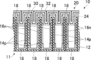
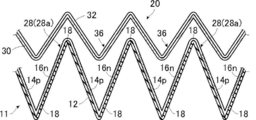
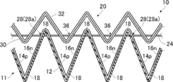
- FIG. 1A is a schematic front view of an example of the thermoelectric conversion module of the present invention.
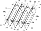
- FIG. 1B is a schematic perspective view of the thermoelectric conversion module shown in FIG. 1A.
- FIG. 1C is a schematic front view showing a state in which the bellows of the thermoelectric conversion module shown in FIG. 1A is closed.
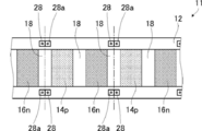
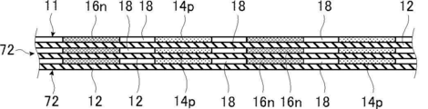
- FIG. 2 is a conceptual diagram for explaining the thermoelectric conversion module shown in FIG. 1.
- FIG. 3 is a schematic front view of another example of the thermoelectric conversion module of the present invention.
- FIG. 4A is a schematic front view of another example of the thermoelectric conversion module of the present invention.
- FIG. 4B is a schematic front view illustrating a state in which the bellows of the thermoelectric conversion module illustrated in FIG. 4A is closed.
- FIG. 4A is a schematic front view of an example of the thermoelectric conversion module of the present invention.
- FIG. 4B is a schematic front view illustrating a state in which the bellows of the thermoelectric conversion module illustrated in
- FIG. 5 is a schematic front view of another example of the thermoelectric conversion module of the present invention.
- FIG. 6 is a schematic front view of another example of the thermoelectric conversion module of the present invention.
- FIG. 7 is a conceptual diagram for explaining another example of the thermoelectric conversion module of the present invention.
- FIG. 8 is a schematic front view of another example of the thermoelectric conversion module of the present invention.
- FIG. 9 is a schematic front view of another example of the thermoelectric conversion module of the present invention.
- FIG. 10 is a conceptual diagram for explaining another example of the thermoelectric conversion module of the present invention.
- FIG. 11 is a conceptual diagram for explaining another example of the thermoelectric conversion module of the present invention.
- FIG. 12 is a schematic front view of an example of the thermally conductive laminate of the present invention.
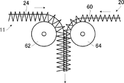
- FIG. 13 is a schematic front view for demonstrating an example of the 1st aspect of the manufacturing method of the thermoelectric conversion module of this invention.
- FIG. 14 is a conceptual diagram for explaining an example of the first aspect of the method for manufacturing a thermoelectric conversion module of the present invention.
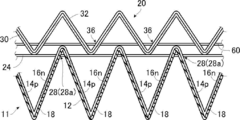
- FIG. 15A is a schematic front view for explaining an example of the first aspect of the manufacturing method of the thermoelectric conversion module of the present invention.
- FIG. 15B is a schematic front view for explaining an example of the first aspect of the method for producing the thermoelectric conversion module of the present invention.
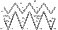
- FIG. 16A is a schematic front view for explaining an example of the first aspect of the manufacturing method of the thermoelectric conversion module of the present invention.
- FIG. 16B is a schematic front view for explaining an example of the first aspect of the method for producing the thermoelectric conversion module of the present invention.
- FIG. 17A is a schematic front view for explaining an example of a second aspect of the method for manufacturing a thermoelectric conversion module of the present invention.
- FIG. 17B is a schematic front view for explaining an example of the second aspect of the method for manufacturing the thermoelectric conversion module of the present invention.
- FIG. 17C is a schematic front view for explaining an example of the second aspect of the method for manufacturing the thermoelectric conversion module of the present invention.
- thermoelectric conversion module and the thermally conductive laminate of the present invention and the method of manufacturing the thermoelectric conversion module and the method of manufacturing the thermally conductive laminate will be described in detail based on preferred embodiments shown in the accompanying drawings.
- a numerical range expressed using “to” means a range including numerical values described before and after “to” as a lower limit value and an upper limit value.
- FIG. 1A to 1C conceptually show an example of the thermoelectric conversion module of the present invention.
- 1A is a schematic front view
- FIG. 1B is a schematic perspective view
- FIG. 1C is a schematic front view showing a state in which the bellows of the thermoelectric conversion module 10 is closed.
- thermoelectric conversion module 10 of this invention in the surface direction of the module main body 11.
- FIG. 1C the bellows-like folded portion is shown in a rectangular shape so that the configuration and each member of the thermoelectric conversion module 10 can be clearly shown.
- the state where the bellows is closed is a state in which the thermoelectric conversion module 10 shown in FIG. 1A is compressed in the lateral direction in the drawing. Therefore, in the state where the bellows of the thermoelectric conversion module 10 is closed, the fold-back portion that has been folded and valley-folded as described later has an acute angle. The same applies to FIG. 4B described later.
- the term “laminated” refers to a state in which the concave and convex portions of the bellows, that is, the mountain fold portion and the valley fold portion, are combined and the convex portions are inserted into the respective concave portions facing the maximum surface. This includes not only a state in which the opposing surfaces are in full contact, but also a state in which some or all of the opposing surfaces of the stacked bellows are held apart from each other. Therefore, in the example shown in FIG. 1A, the module main body 11 and the insulating member 20 are entirely separated from each other. For example, in a stacked state, the module main body 11 and the insulating member 20 protrude upward in the drawing.
- the state which the surface which opposes may contact in the top part of a part may be sufficient.
- the module body 11 and the insulating member 20 may be stacked, and the entire surface of the insulating member 20 may be in contact with the opposing surface of the module body 11.
- the module main body 11 includes a support 12, a P-type thermoelectric conversion layer 14 p, an N-type thermoelectric conversion layer 16 n, and a connection electrode 18.
- the support 12 is hatched, and the P-type thermoelectric conversion layer 14p and the N-type thermoelectric conversion layer 16n are shaded.
- FIG. 2 FIGS. 10 and 11 to be described later
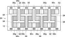
- the module main body 11 is formed with connection electrodes 18 having a fixed length at regular intervals in the longitudinal direction of the support 12 on one surface of the long support 12.
- P-type thermoelectric conversion layers 14p and N-type thermoelectric conversion layers 16n having a predetermined length at regular intervals in the longitudinal direction of the support 12 are alternately formed.
- the “longitudinal direction of the support 12” is also referred to as “longitudinal direction”.
- the width direction of the support 12, that is, the direction orthogonal to the longitudinal direction is also referred to as “width direction”. Accordingly, the width direction is a direction perpendicular to the paper surface in FIGS. 1A and 1C.
- the length and interval in the longitudinal direction are the length and interval in a state where the module main body 11 is extended in a planar shape.
- the module body 11 has a bellows-like shape that is alternately folded back into a mountain fold and a valley fold by a fold line parallel to the width direction of the support 12 at the center in the longitudinal direction of the connection electrode 18. Accordingly, the module main body 11 alternately has mountain folds and valley folds in the longitudinal direction and has top and bottom alternately by bellows-like folding. Therefore, the longitudinal direction coincides with the inclination direction of the inclined surface by the bellows-like folding.
- the support 12 is folded inward on the inner side, that is, the side on which the connection electrode 18 is convex, and the outer side, ie, on the side in which the connection electrode 18 is concave, is valley-folded. . That is, the upper side in FIG. 1A is the mountain fold side, and the lower side is the valley fold side.
- the module body 11 includes a P-type thermoelectric conversion layer 14p and an N-type thermoelectric conversion layer 16n that are adjacent to each other in the longitudinal direction, with the P-type thermoelectric conversion layer 14p and the N-type thermoelectric conversion layer 16n arranged alternately in the longitudinal direction. Are connected in series by the connection electrode 18. Further, as described above, the module main body 11 is folded in a mountain fold and a valley fold at the longitudinal center of the connection electrode 18 to have a bellows shape. Such a module main body 11 generates heat by providing a high temperature heat source on the lower side of FIG. 1A and heat radiating means such as heat radiating fins on the upper side, and generating a temperature difference in the vertical direction in FIG. 1A. . In other words, the P-type thermoelectric conversion layer 14p and the N-type thermoelectric conversion layer 16n formed on the inclined surface of the support 12 generate electricity by causing a temperature difference in the thermoelectric conversion layer in the longitudinal direction.
- the support (substrate) 12 is long, flexible, and insulative.
- the support 12 if it has flexibility and insulating properties, it is a long sheet-like material (film) used in a known thermoelectric conversion module using a flexible support.
- film a sheet-like material used in a known thermoelectric conversion module using a flexible support.
- various types are available.
- polyester resins such as polyethylene terephthalate, polyethylene isophthalate, polyethylene naphthalate, polybutylene terephthalate, poly (1,4-cyclohexylenedimethylene terephthalate), polyethylene-2,6-phthalenedicarboxylate, polyimide
- the sheet-like material are polycarbonate, polypropylene, polyethersulfone, cycloolefin polymer, polyetheretherketone (PEEK), triacetylcellulose (TAC), and other resins, glass epoxy, liquid crystalline polyester, and the like.
- the sheet-like material which consists of a polyimide, a polyethylene terephthalate, a polyethylene naphthalate etc. is utilized suitably by points, such as thermal conductivity, heat resistance, solvent resistance, availability, and economical efficiency.
- the thickness of the support 12 may be set as appropriate so that sufficient flexibility can be obtained and the thickness that functions as the support 12 can be set according to the material for forming the support 12. Note that the length and width of the support 12 may be appropriately set according to the size and use of the module body 11.
- a through hole 28 is formed in the inclined surface by folding in the vicinity of both ends in the width direction of the support 12.
- the through hole 28 is arranged in the width direction outside the region where the P-type thermoelectric conversion layer 14p and the N-type thermoelectric conversion layer 16n in the width direction of the support 12 and the connection electrode 18 are formed.
- the through hole 28 is symmetrical with respect to the center of the connection electrode 18 in the longitudinal direction, that is, the fold-back line of the mountain fold shown by a one-dot chain line in FIG. A pair is formed at the position.
- the longitudinal direction and the inclined direction of the inclined surface are the same direction.
- the through hole 28 is preferably formed at a position that is linear in the longitudinal direction when the support 12 is folded back in a bellows shape. That is, the through hole 28 is preferably formed at a position where a single straight line that is long in the longitudinal direction can be inserted when the support 12 is folded in a bellows shape.
- the wire 24 penetrates the module main body 11 and the insulating member 20 through the through hole 28.
- symbol 28a is a reinforcement member for reinforcing the through-hole 28 provided as needed.
- the reinforcing member 28a may be formed using a known hole reinforcing member such as a metal or a resin material.
- thermoelectric conversion material of the P-type thermoelectric conversion layer 14p When a nickel alloy is used as the thermoelectric conversion material of the P-type thermoelectric conversion layer 14p, chromel containing nickel and chromium as main components is typical. In the case where a nickel alloy is used as the thermoelectric material of the N-type thermoelectric conversion layer 16n, constantan mainly composed of copper and nickel is typical. When nickel or a nickel alloy is used as the P-type thermoelectric conversion layer 14p and the N-type thermoelectric conversion layer 16n, and when nickel or a nickel alloy is also used as the connection electrode 18, the P-type thermoelectric conversion layer 14p and the N-type thermoelectric conversion layer 16n and the connection electrode 18 may be integrally formed.
- thermoelectric conversion materials that can be used for the P-type thermoelectric conversion layer 14p and the N-type thermoelectric conversion layer 16n include the following materials in addition to nickel and nickel alloys.
- thermoelectric conversion material used for the P-type thermoelectric conversion layer 14p and the N-type thermoelectric conversion layer 16n a material that can be pasted so that a film can be formed by coating or printing can be used.
- thermoelectric conversion materials include organic thermoelectric conversion materials such as conductive polymers or conductive nanocarbon materials.
- the conductive polymer include a polymer compound having a conjugated molecular structure (conjugated polymer).
- conjugated polymer conjugated molecular structure
- specific examples include known ⁇ -conjugated polymers such as polyaniline, polyphenylene vinylene, polypyrrole, polythiophene, polyfluorene, acetylene, and polyphenylene.
- polydioxythiophene can be preferably used.
- the conductive nanocarbon material include carbon nanotubes, carbon nanofibers, graphite, graphene, and carbon nanoparticles. These may be used alone or in combination of two or more. Among these, carbon nanotubes are preferably used because the thermoelectric characteristics are better. In the following description, “carbon nanotube” is also referred to as “CNT”.
- CNT is a single-layer CNT in which one carbon film (graphene sheet) is wound in a cylindrical shape, two-layer CNT in which two graphene sheets are concentrically wound, and a plurality of graphene sheets in a concentric circle
- multi-walled CNTs wound in a shape In the present invention, single-walled CNTs, double-walled CNTs, and multilayered CNTs may be used alone, or two or more kinds may be used in combination.
- single-walled CNT and double-walled CNT having excellent properties in terms of conductivity and semiconductor properties are preferably used, and single-walled CNT is more preferably used.
- Single-walled CNTs may be semiconducting or metallic, and both may be used in combination. When using both semiconducting CNT and metallic CNT, the content ratio of both can be adjusted suitably.
- the CNT may contain a metal or the like, or may contain a molecule such as fullerene.
- the average length of the CNT is not particularly limited and can be selected as appropriate. Specifically, although it depends on the distance between the electrodes, the average length of the CNT is preferably 0.01 to 2000 ⁇ m, more preferably 0.1 to 1000 ⁇ m from the viewpoints of manufacturability, film formability, conductivity, and the like. 1 to 1000 ⁇ m is particularly preferable.
- the diameter of the CNT is not particularly limited, but is preferably 0.4 to 100 nm, more preferably 50 nm or less, and particularly preferably 15 nm or less from the viewpoint of durability, transparency, film formability, conductivity, and the like.
- the diameter of the CNT is preferably 0.5 to 2.2 nm, more preferably 1.0 to 2.2 nm, and particularly preferably 1.5 to 2.0 nm.
- CNT may contain defective CNT. Such CNT defects are preferably reduced in order to reduce the conductivity of the thermoelectric conversion layer.
- the amount of CNT defects can be estimated by the ratio G / D between the G-band and D-band of the Raman spectrum. It can be estimated that the higher the G / D ratio, the less the amount of defects, the CNT material.
- the CNT preferably has a G / D ratio of 10 or more, more preferably 30 or more.
- CNTs modified or treated with CNTs can be used. Modification or treatment methods include a method of encapsulating a ferrocene derivative or nitrogen-substituted fullerene (azafullerene), a method of doping an alkali metal (such as potassium) or a metal element (such as indium) into the CNT by an ion doping method, CNT in a vacuum The method etc. which heat this are illustrated.
- nanocarbon such as carbon nanohorn, carbon nanocoil, carbon nanobead, graphite, graphene, and amorphous carbon may be included.
- thermoelectric conversion layer preferably contains a P-type dopant or an N-type dopant.
- P-type dopant P-type dopants include halogens (iodine, bromine, etc.), Lewis acids (PF 5 , AsF 5, etc.), proton acids (hydrochloric acid, sulfuric acid, etc.), transition metal halides (FeCl 3 , SnCl 4 etc.), metal oxides (Molybdenum oxide, vanadium oxide, etc.), organic electron accepting substances and the like are exemplified.
- organic electron accepting substance examples include 2,3,5,6-tetrafluoro-7,7,8,8-tetracyanoquinodimethane, 2,5-dimethyl-7,7,8,8- Tetracyanoquinodimethane such as tetracyanoquinodimethane, 2-fluoro-7,7,8,8-tetracyanoquinodimethane, 2,5-difluoro-7,7,8,8-tetracyanoquinodimethane (TCNQ) derivatives, 2,3-dichloro-5,6-dicyano-p-benzoquinone, benzoquinone derivatives such as tetrafluoro-1,4-benzoquinone, etc., 5,8H-5,8-bis (dicyanomethylene) quinoxaline, Preferred examples include dipyrazino [2,3-f: 2 ′, 3′-h] quinoxaline-2,3,6,7,10,11-hexacarbonitrile.
- organic electron-accepting substances such as TCNQ (tetracyanoquinodimethane) derivatives or benzoquinone derivatives are preferably exemplified in terms of material stability, compatibility with CNTs, and the like.
- TCNQ tetracyanoquinodimethane
- benzoquinone derivatives are preferably exemplified in terms of material stability, compatibility with CNTs, and the like.
- Any of the P-type dopant and the N-type dopant may be used alone or in combination of two or more.
- N-type dopant include (1) alkali metals such as sodium and potassium, (2) phosphines such as triphenylphosphine and ethylenebis (diphenylphosphine), and (3) polymers such as polyvinylpyrrolidone and polyethyleneimine. These materials can be used.
- polyethylene glycol type higher alcohol ethylene oxide adducts such as phenol or naphthol
- fatty acid ethylene oxide adducts polyhydric alcohol fatty acid ester ethylene oxide adducts, higher alkylamine ethylene oxide adducts, fatty acids Amide ethylene oxide adduct, fat ethylene oxide adduct, polypropylene glycol ethylene oxide adduct, dimethylsiloxane-ethylene oxide block copolymer, dimethylsiloxane- (propylene oxide-ethylene oxide) block copolymer, etc.
- acetylene glycol ethylene glycol type higher alcohol ethylene oxide adduct
- thermoelectric conversion layer 14p and the N-type thermoelectric conversion layer 16n a thermoelectric conversion layer in which a thermoelectric conversion material is dispersed in a resin material (binder) is also preferably used.
- distributing a conductive nano carbon material to a resin material is illustrated more suitably.
- a thermoelectric conversion layer in which CNT is dispersed in a resin material is particularly preferably exemplified in that high conductivity is obtained.
- Various known non-conductive resin materials (polymer materials) can be used as the resin material. Specific examples include vinyl compounds, (meth) acrylate compounds, carbonate compounds, ester compounds, epoxy compounds, siloxane compounds, and gelatin.
- examples of the vinyl compound include polystyrene, polyvinyl naphthalene, polyvinyl acetate, polyvinyl phenol, polyvinyl butyral, and the like.
- examples of the (meth) acrylate compound include polymethyl (meth) acrylate, polyethyl (meth) acrylate, polyphenoxy (poly) ethylene glycol (meth) acrylate, polybenzyl (meth) acrylate and the like.
- examples of the carbonate compound include bisphenol Z-type polycarbonate and bisphenol C-type polycarbonate. As the ester compound, amorphous polyester is exemplified.
- Preferred examples include polystyrene, polyvinyl butyral, (meth) acrylate compounds, carbonate compounds, and ester compounds, and more preferred are polyvinyl butyral, polyphenoxy (poly) ethylene glycol (meth) acrylate, polybenzyl (meth) acrylate, and amorphous.
- An example is a reactive polyester.
- the quantity ratio of the resin material to the thermoelectric conversion material is the material used, the required thermoelectric conversion efficiency, the viscosity or solid content concentration of the solution affecting printing, etc. It may be set appropriately according to the above.
- thermoelectric conversion layer mainly composed of CNT and a surfactant is also preferably used.
- the thermoelectric conversion layer can be formed with a coating composition to which a surfactant is added. Therefore, the thermoelectric conversion layer can be formed with a coating composition in which CNTs are reasonably dispersed. As a result, good thermoelectric conversion performance can be obtained by the thermoelectric conversion layer containing many CNTs that are long and have few defects.
- the surfactant a known surfactant can be used as long as it has a function of dispersing CNTs. More specifically, various surfactants can be used as long as they have a group that dissolves in water, a polar solvent, or a mixture of water and a polar solvent and adsorbs CNTs. Accordingly, the surfactant may be ionic or nonionic. The ionic surfactant may be any of cationic, anionic and amphoteric.
- anionic surfactant examples include alkylbenzene sulfonates such as dodecylbenzene sulfonic acid, aromatic sulfonic acid surfactants such as dodecyl phenyl ether sulfonate, monosoap anionic surfactants, ether sulfates Surfactants, phosphate surfactants and carboxylic acid surfactants such as sodium deoxycholate or sodium cholate, carboxymethylcellulose and salts thereof (sodium salt, ammonium salt, etc.), ammonium polystyrene sulfonate, Examples thereof include water-soluble polymers such as polystyrene sulfonate sodium salt.
- Examples of the cationic surfactant include alkylamine salts and quaternary ammonium salts.
- amphoteric surfactants include alkyl betaine surfactants and amine oxide surfactants.
- examples of nonionic surfactants include sugar ester surfactants such as sorbitan fatty acid esters, fatty acid ester surfactants such as polyoxyethylene resin acid esters, ether surfactants such as polyoxyethylene alkyl ether, and the like. Is exemplified. Among these, ionic surfactants are preferably used, and among them, cholate or deoxycholate is preferably used.
- thermoelectric conversion layer made of an organic material, optionally, SiO 2, TiO 2, Al 2 O 3, may have an inorganic material such as ZrO 2.
- a thermoelectric conversion layer contains an inorganic material, it is preferable that the content is 20 mass% or less, and it is more preferable that it is 10 mass% or less.
- thermoelectric conversion layer 14p and an N-type thermoelectric conversion layer 16n may be formed by a known method.
- the following method is illustrated as an example.
- a coating composition for forming a thermoelectric conversion layer containing a thermoelectric conversion material and necessary components such as a surfactant is prepared.
- the coating composition used as the thermoelectric conversion layer prepared is patterned and apply
- the coating composition may be applied by a known method such as a method using a mask or a printing method. After applying the coating composition, the coating composition is dried by a method according to the resin material to form a thermoelectric conversion layer.
- thermoelectric conversion layer may be patterned by etching or the like after applying the prepared coating composition to be the thermoelectric conversion layer on the entire surface of the insulating support and drying it.
- thermoelectric conversion layer mainly composed of CNT and a surfactant
- the thermoelectric conversion layer is immersed in a solvent that dissolves the surfactant
- the thermoelectric conversion layer is preferably formed by washing the thermoelectric conversion layer with a solvent that dissolves the surfactant and then drying. Thereby, the surfactant is removed from the thermoelectric conversion layer, and a thermoelectric conversion layer in which the surfactant / CNT mass ratio is extremely small, more preferably no surfactant is present, can be formed.
- the thermoelectric conversion layer is preferably patterned by printing.
- thermoelectric conversion layer As the printing method, various known printing methods such as screen printing, metal mask printing, and inkjet can be used. In addition, when pattern-forming a thermoelectric conversion layer using the coating composition containing CNT, it is more preferable to use metal mask printing.
- the printing conditions may be appropriately set depending on the physical properties (solid content concentration, viscosity, viscoelastic physical properties) of the coating composition to be used, the opening size, the numerical aperture, the opening shape, the printing area, etc.
- the sizes of the P-type thermoelectric conversion layer 14p and the N-type thermoelectric conversion layer 16n may be set as appropriate according to the size of the module body 11, the width of the support 12, the size of the connection electrode 18, and the like. In the present invention, the size is the size in the surface direction of the support 12. As described above, the P-type thermoelectric conversion layer 14p and the N-type thermoelectric conversion layer 16n have the same length in the longitudinal direction. Further, since the thermoelectric conversion layers are formed at regular intervals, the P-type thermoelectric conversion layers 14p and the N-type thermoelectric conversion layers 16n are alternately formed at the same intervals.
- connection electrodes 18 are formed on the formation surfaces of the P-type thermoelectric conversion layer 14 p and the N-type thermoelectric conversion layer 16 n of the support 12.
- the connection electrode 18 electrically connects the P-type thermoelectric conversion layers 14p and the N-type thermoelectric conversion layers 16n alternately formed in the longitudinal direction in series.
- the thermoelectric conversion layer is formed with a certain length in the longitudinal direction at regular intervals. Accordingly, the connection electrodes 18 having a certain length are formed at regular intervals.
- the module body 11 is folded back at the center in the longitudinal direction of the connection electrode 18 by a mountain fold and a valley fold along a fold line parallel to the width direction.
- connection electrode 18 Any material can be used for the connection electrode 18 as long as it has a necessary conductivity.
- various materials such as copper, silver, gold, platinum, nickel, aluminum, constantan, chromium, indium, iron, copper alloy, and other devices such as indium tin oxide (ITO) and zinc oxide (ZnO) Examples include materials used as transparent electrodes.
- ITO indium tin oxide
- ZnO zinc oxide
- the connection electrode 18 may be a laminated electrode such as a configuration in which a copper layer is formed on a chromium layer.
- connection electrode 18 may be patterned by a known method according to the material for forming the connection electrode 18, such as a vapor deposition method such as vacuum deposition or sputtering, or a coating method such as printing.
- connection electrode 18 may be set as appropriate according to the size of the module body 11, the width of the support 12, the sizes of the P-type thermoelectric conversion layer 14p and the N-type thermoelectric conversion layer 16n, and the like.
- the thickness of the connection electrode 18 may be appropriately set according to the forming material so that the P-type thermoelectric conversion layer 14p and the N-type thermoelectric conversion layer 16n can ensure sufficient conductivity.
- Such a module main body 11 can be produced by a known method.
- the thermoelectric conversion layer and the connection electrode 18 are formed by patterning on a long plate-like support 12 by a known method according to the forming material.
- a through hole 28 or further a reinforcing member 28a is formed at a position corresponding to the connection electrode 18 that is folded in the longitudinal direction.
- a known sheet-like material is bent, such as press working or processing with a roller having protrusions, and folded into a bellows shape to obtain a bellows-like module body 11.
- These operations are preferably performed by so-called roll-to-roll, in which various processes are continuously performed while the support 12 (substrate to be processed) is conveyed in the longitudinal direction.
- the module 10 has a configuration in which the module main body 11 and the insulating member 20 are stacked and the wire 24 is inserted through both of them.
- the insulating member 20 is a kind of bellows-like member in the present invention.
- the insulating member 20 is formed by forming a heat conductive layer 32 on one surface of a long support 30 (insulating layer) having insulating properties and flexibility. It is a bellows shape that is alternately folded by valley folds. In this example, when the insulating member 20 is folded back, the support 30 is folded inward on the side where the heat conductive layer 32 is convex, and the support 12 is outside on the side where the heat conductive layer 32 is concave. The valley fold.
- the insulating member 20 is laminated on the module body 11 with the support 30 facing the connection electrode 18 of the module body 11 and the surface on which the thermoelectric conversion layer is formed, with unevenness.
- the heat conductive layer 32 is a layer formed of a material having high heat conductivity.
- the insulating member 20 has the heat conductive layer 32 as a preferred embodiment. Therefore, the insulating member 20 does not necessarily need to have the heat conductive layer 32, and the insulating member 20 may be configured with only the insulating support 30. However, since the insulating member 20 has the heat conductive layer 32, the insulating member 20 also acts as a heat radiating member. Therefore, the temperature difference of the thermoelectric conversion layer can be increased to improve the amount of power generation. Furthermore, the bellows shape of the insulating member 20 can be suitably maintained by forming the heat conductive layer 32 with a metal material or the like.
- the heat conductive layer 32 As a material for forming the heat conductive layer 32, various materials used for so-called heat radiation fins can be used. Specific examples include various metal materials such as copper and aluminum, inorganic compounds such as alumina, boron nitride, and aluminum nitride, and carbon materials such as graphite. Among these, metal materials such as copper and aluminum are preferably used.
- the thickness of the heat conductive layer 32 is set as appropriate according to the material for forming the heat conductive layer 32, the size of the unevenness of the insulating member 20, and the like to obtain the necessary heat conductivity, that is, the heat dissipation effect. do it. Similar to the connection electrode 18, the heat conductive layer 32 may be formed by a known method such as a vacuum film formation method such as vacuum deposition or a coating method such as printing, depending on the forming material.
- through holes 36 are formed in the vicinity of both end portions in the width direction of the inclined surface due to bellows-like folding.
- the through hole 36 of the insulating member 20 is formed at the same position as the through hole 28 of the module body 11 in the width direction.
- a pair is formed at the valley fold portion at positions symmetrical to the folding line of the valley fold.
- the through hole 36 is preferably formed at a position that is linear in the longitudinal direction when the insulating member 20 is folded back in a bellows shape.
- the through hole 36 is preferably formed so that the through hole 28 of the module body 11 is also linear when the insulating member 20 is stacked on the module body 11.
- the insulating member 20 can also be produced by a known method, like the module body 11 described above.
- the heat conductive layer 32 is formed on the entire surface of the flat plate-like long support 30 by a known method according to the forming material, and the through hole 34 is formed at a predetermined position of the support 30. .
- a known sheet-like material is bent, such as press working or processing with a roller having protrusions, and folded into a bellows shape, thereby forming the bellows-like insulating member 20.
- These operations are preferably performed in a roll-to-roll manner as in the module body 11.
- the bellows-like insulating member 20 is laminated on the bellows-like module main body 11 so as to be uneven, and the through hole 28 of the module main body 11 and the through hole 36 of the insulating member 20 are laminated.
- a flexible wire 24 that passes through the module main body 11 and the insulating member 20. That is, the module main body 11 and the insulating member 20 are combined, and both are inserted by the wire 24, thereby maintaining the combined state of the module main body 11 and the insulating member 20 by matching the irregularities of the bellows.
- the present invention combines the bellows-like module main body 11 with the bellows-like insulating member 20 and the heat radiating member, and the module main body 11 and the insulating member 20 etc. stably.
- a module 10 is obtained that can maintain the combined configuration, improve handling, and has flexibility, and can be easily attached to, for example, a tubular heat source with good handling. ing.
- thermoelectric conversion module having a bellows shape and flexibility
- the folded support body can be reduced in the longitudinal direction, that is, thermoelectric conversion, for the purpose of improving the heat transfer efficiency, the mounting density of the thermoelectric conversion elements, etc. It is advantageous to compress the layers in the arrangement direction so that the bellows is closed as much as possible.
- thermoelectric conversion module when the bellows is closed, the electrodes come into contact with each other at the mountain fold portion, causing a short circuit and no power generation. Therefore, when closing the bellows of the bellows-like thermoelectric conversion module, it is conceivable to combine insulating members. In the bellows-like thermoelectric conversion module, when some members are combined, it is naturally preferable that the members to be combined are also bellows-like.
- thermoelectric conversion module in order to prevent contact between electrodes in a mountain fold, an insulating member obtained by folding a long insulator into a bellows shape is laminated on the thermoelectric conversion module, and the insulating member
- the structure which covers the connection electrode of a mountain fold part can be considered. Thereby, even if it is in the state which closed the bellows of the thermoelectric conversion module, it can prevent that the connection electrode of a mountain fold part short-circuits.
- the module 10 of the present invention not only laminates the flexible bellows-like module main body 11 and the flexible bellows-like insulating member 20 with the concaves and convexes, but also the module main body 11.
- the wire 24 penetrates the module main body 11 and the insulating member 20 through the through hole 28 formed in the inclined surface and the through hole 36 formed in the inclined surface of the insulating member 20. Therefore, even when the module 10 is deformed such as by bending or only one of the module main body 11 and the insulating member 20 is supported, the module main body 11 and the insulating member 20 do not dissociate.
- the wire 24 is also flexible, and can be bent in the longitudinal direction. For example, it is bent into a curved shape and attached to a tubular heat source. It is possible to attach to various shapes of heat sources.
- the wire 24, that is, the linear member is inserted through the module main body 11 and the insulating member 20, the bellows can be easily closed by pressing in the longitudinal direction, and the degree of compression by the pressed state, that is, the bellows The interval between the concaves and convexes (the bellows interval) can be easily changed in whole or in part.
- the module main body 11 and the insulating member 20 do not dissociate. For this reason, it is easy to handle and can be mounted with good workability even when mounted on a heat source having various shapes such as a curved surface and a refracted surface.
- the wire 24 can be a variety of flexible linear members. Specifically, metal wires such as threads (strings) and wires, metal wires coated with an insulating material, and the like are exemplified.
- the penetration position of the wire 24 in the module main body 11 is preferably other than the portion where the thermoelectric conversion layer and the connection electrode 18 are formed. Thereby, it can prevent that the area of a thermoelectric conversion layer or an electrode reduces, and the intensity
- the wire 24 penetrates the inclined surface at the same position as the connection electrode 18 in the longitudinal direction (inclination direction of the inclined surface) in the width direction and in the longitudinal direction (inclination direction of the inclined surface) as in the illustrated example. preferable.
- the bellows When the module 10 is pressed in the longitudinal direction and the bellows is closed (the bellows is folded) as shown in FIG. Therefore, when the bellows is closed by inserting the wire 24 outside the connection electrode 18 in the width direction and at the same position as the connection electrode 18 in the longitudinal direction as in the illustrated example, it is usually formed of a metal material.
- the connecting electrode can be brought into close contact with the support body 12, and the temperature unevenness of the thermoelectric conversion layer in the width direction and the longitudinal direction can be reduced on the mountain fold side, and efficient power generation can be performed.
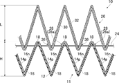
- the insulating member 20 is provided with the heat conductive layer 32 made of a metal material or the like on one surface of the insulating support 30 and also functions as a heat radiating member. Therefore, as conceptually shown in FIG. 3, the height of the mountain fold portion of the insulating member 20 is made higher than the height of the mountain fold portion of the module main body 11, and the mountain fold portion of the insulating member 20 is made to be the module main body 11. You may make it protrude largely from. Thereby, the insulating member 20 is made to act as a radiation fin, the temperature difference of a thermoelectric conversion layer is enlarged, and the electric power generation amount of the module 10 can be enlarged.
- connection electrode 18 since the wire 24 is inserted in the longitudinal direction at the same position as the connection electrode 18, the connection electrode 18 having high thermal conductivity and the heat conductive layer 32 of the insulating member 20 acting as a heat radiation fin. Can be brought into close contact with each other through the support 30, and the heat dissipation effect can be further improved.
- the protrusion amount L is 0.5 to 5 times the height H. That is, it is preferable to satisfy “0.5H ⁇ L ⁇ 5H”.
- the module 10 can be prevented from becoming unnecessarily large, and the degree of freedom of installation location can be reduced. Improvement, expansion of applications of the module 10 and the like can be achieved.
- the height of the mountain folds of the insulating member 20 may be different. That is, the insulating member 20 may have irregularities with different heights (mountain folds with different heights). This configuration is particularly effective when the mountain-folded portion of the insulating member 20 is greatly protruded from the module body 11 as shown in FIG.
- the protrusion amount of the mountain fold portion of the insulating member 20 is set to be the same as the protrusion amount L described above, the protrusion amount at the highest mountain fold portion is the maximum protrusion amount L1, and the protrusion amount of the other mountain fold portions is L2.
- the difference Ld between the maximum protruding amount L1 and the protruding amount L2 is set to 1/2 or more of the maximum protruding amount L1, whereby the protruding portion of the insulating member 20 in the module 10 is obtained.
- FIG. 4A conceptually shows another example of the thermoelectric conversion module of the present invention.
- FIG. 4B conceptually shows a state in which the bellows of the thermoelectric conversion module shown in FIG. 4A is closed.
- the thermoelectric conversion module shown to FIG. 4A etc. uses many the same members as the thermoelectric conversion module shown to above-mentioned FIG. 1A etc., the same code
- the other aspects of the thermoelectric conversion module of the present invention are the same, including the thermally conductive laminate of the present invention described later.
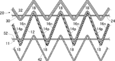
- the module 10 shown in FIGS. 1A to 1C has a configuration in which an insulating member 20 is laminated on the module main body 11 with the bellows unevenness, and a wire 24 is inserted through both of them.
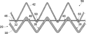
- a bellows-like heat radiation member 42 is further laminated on the insulating member 20 of the module 10 with the bellows unevenness, and the insulation member 20 and the heat radiation member 42 A wire 46 as a two-line member is inserted. That is, the heat radiating member 42 is laminated on the surface of the insulating member 20 opposite to the module main body 11.
- the heat dissipation member 42 is one of the bellows-like members in the present invention.
- the thermoelectric conversion module 40 is also referred to as “module 40”.
- the heat dissipating member 42 is a bellows shape obtained by alternately folding a sheet-like material made of a material having high thermal conductivity by mountain folds and valley folds.
- the side that protrudes toward the insulating member 20 of the heat dissipation member 42 is a valley fold, and the opposite side is a mountain fold.
- the material for forming the heat dissipation member 42 various materials exemplified as the material for forming the heat conductive layer 32, such as a metal material, can be used.
- the folding process for forming the bellows may be performed by a known method such as press working.
- the through hole 48 is formed in the vicinity of both end portions in the width direction on the inclined surface of the insulating member 20 formed by the bellows-like folding.
- a pair of through holes 48 are formed symmetrically with the folding line of the mountain fold at the mountain fold.
- the through hole 48 is preferably formed to be linear in the longitudinal direction when the insulating member 20 is folded back in a bellows shape.
- the through holes 50 are also formed in the vicinity of both end portions in the width direction on the inclined surface of the heat radiating member 42 formed by the bellows.
- the through hole 50 is formed at the same position as the through hole 48 in the width direction.
- a pair of through holes 50 are formed in the longitudinal direction at the valley fold portion symmetrically with respect to the folding line of the valley fold.
- the through hole 50 is preferably formed to be linear in the longitudinal direction when the heat dissipation member 42 is folded back in a bellows shape. Further, the through hole 50 is preferably formed so that the through hole 48 of the insulating member 20 is also linear when the heat radiating member 42 is laminated on the insulating member 20.
- the module 40 is a laminate of the module body 11 and the insulating member 20 through which the wire 24 is inserted, that is, the heat radiating member 42 formed of a heat conductive material is laminated on the insulating member 20 of the module 10 described above,
- the wire 46 is inserted through the insulating member 20 and the heat radiating member 42 through the through hole 48 of the insulating member 20 and the through hole 50 of the heat radiating member 42. Therefore, in the module 40, since the heat dissipation member 42 acts as a heat dissipation fin, the temperature difference of the thermoelectric conversion layer can be increased to obtain a large amount of power generation.
- the wire 24 is inserted through the module body 11 and the insulating member 20, and the wire 46 is inserted through the insulating member 20 and the heat dissipation member 42. Therefore, as in the module 10 described above, each member does not dissociate, and the bellows can be closed and the irregularities of the bellows can be easily adjusted, that is, the bellows spacing can be easily adjusted.
- mounting can be performed with good workability.
- the protrusion amount of the mountain fold portion of the heat radiating member 42 is the same as the example shown in FIG. Is preferable.
- the heat radiating member 42 may have mountain fold portions having different heights, that is, unevenness having different heights. In this case, it is preferable that the difference in height of the mountain folds of the heat radiating part is the same as in the above-described example.
- thermoelectric conversion module of the present invention is not limited to this. That is, according to the positional relationship among the module main body 11, the insulating member 20, and the heat radiating member 42, the size of the irregularities of the bellows, the insertion amount of the convex portions into the concave portions between the bellows, the module main body 11 if possible.
- a common wire may be inserted through the insulating member 20 and the heat dissipation member 42.
- the thermoelectric conversion module of the present invention has a configuration in which the stacked module main body 11 and the insulating member 20 shown in FIGS. 1A to 1C are inserted with wires 24, and the stacked module main body 11 shown in FIGS. 4A and 4B are insulated.
- the bellows-shaped module body 11 is connected to the insulating member 20.
- Various configurations in which the bellows-like members are laminated can be used.
- the heat radiating member 42 is provided on the support 12 side opposite to the insulating member 20 of the module main body 11, and the module main body 11 is sandwiched between the insulating member 20 on the mountain fold side and the heat radiating member 42 on the valley fold side.
- a configuration is illustrated.
- the heat dissipating member 42 is combined with the irregularities of the bellows so as to sandwich the configuration in which the module body 11 and the insulating member 20 are laminated and the wire 24 is inserted.
- a configuration in which the wire 52 is inserted into the heat radiating member 42 and the module main body 11 and the wire 46 is inserted into the insulating member 20 and the heat radiating member 42 can also be used.
- the insulating member 20 is not provided, and the module main body 11 and the heat radiating member 42 are stacked, with the heat radiating member 42 provided on the lower side of the module main body 11, that is, on the support 12 side.
- the through holes through which the wires (linear members) penetrate are basically the through holes 28 of the module body 11 and the through holes 36 of the insulating member 20, the through holes 48 of the insulating member 20 and the through holes of the heat radiating member 42. Since it is the same, it is omitted in FIGS.
- the insulating member 20 and the heat radiating member 42 are illustrated as the bellows-like members.
- various members can be used in addition to the bellows-like members.
- examples of the bellows-like member other than the insulating member 20 and the heat dissipation member 42 include a member for adjusting the distance between the bellows.
- the member for adjusting the distance between the bellows may be formed of metal.
- the widths of the insulating member 20 and the heat radiating member 42 are generally equal to the width of the module body 11.
- the present invention is not limited to this.
- FIG. 7 conceptually illustrating the module 10 shown in FIGS. 1A to 1C
- the size of the insulating member 20 in the width direction is made larger than the size of the module body 11 in the width direction.
- the insulating member 20 may protrude from the end in the width direction of the module body 11 on one side in the width direction or on both sides in the width direction.
- FIG. 7 is a view of the module 10 as viewed in the longitudinal direction, that is, FIG. 1A is a view of the module 10 as viewed from the lateral direction.
- the heat radiating member 42 when the heat radiating member 42 is used in addition to the insulating member 20, the insulating member 20 and / or the heat radiating member are similarly formed from the end in the width direction of the module body 11. 42 may protrude. As shown in FIG. 6, when two heat radiating members 42 are provided, one or both heat radiating members 42 may protrude from the end of the module body 11 in the width direction. Further, in the above-described configuration in which the insulating member 20 is not provided and the heat radiating member 42 is provided on the support 12 side of the module main body 11, the heat radiating member 42 protrudes from the end in the width direction of the module main body 11. Also good.
- the insulating member 20 is obtained by forming the heat conductive layer 32 on the surface of the insulating support 30 and can also function as a heat radiating member.
- the heat radiating member 42 is formed of a material having high thermal conductivity. Therefore, as shown in FIG. 7, by projecting the insulating member 20 (heat radiating member 42) from the module main body 11 in the width direction, the region protruding from the module main body 11 of the insulating member 20 acts like a radiating fin. Thus, a good heat dissipation effect can be obtained. Therefore, according to this structure, the temperature difference in the thermoelectric conversion layer of the module main body 11 can be enlarged, and the electric power generation amount in a thermoelectric conversion module can be enlarged.
- the amount of protrusion in the width direction of the insulating member 20 from the module body 11 may be set as appropriate according to the size of the module 10, the assumed installation location of the module 10, and the like. Specifically, as shown in FIG. 7, when the width of the module main body 11 is W and the protrusion amount of the insulating member 20 (heat radiation member 42) in the width direction from the module main body 11 is P, the protrusion amount P
- the width is preferably 0.1 to 10 times the width W of the module body 11. That is, it is preferable to satisfy “0.1 W ⁇ P ⁇ 10 W”.
- the protrusion amount P of the insulating member 20 in the width direction By setting the protrusion amount P of the insulating member 20 in the width direction to be 0.1 times or more the width W of the module main body 11, a sufficient heat dissipation effect can be obtained and the power generation amount can be improved. Further, by making the protruding amount P of the insulating member 20 in the width direction 10 times or less the width W of the module body 11, the module 10 is prevented from becoming unnecessarily large, and the degree of freedom in installation location is improved. The use of the module 10 can be expanded.
- the heat radiating member 42 may protrude from the insulating member 20 as shown in FIG. 4A, but there is almost no protruding amount from the insulating member 20. Also good. That is, when the heat radiating member 42 is protruded in the width direction from the module body 11, the difference between the height of the mountain fold portion of the heat radiating fin and the height of the mountain fold portion of the insulating member 20 is equal to the thickness of the heat radiating member 42. It may be only. The same applies to the thermoelectric conversion modules shown in FIGS. 5 and 6.
- the above example is an example in which the bellows-like module main body 11 is combined with the bellows-like insulating member 20 and / or the bellows-like heat dissipation member 42 as the bellows-like member.
- a bellows-like thermoelectric conversion member can also be used. An example is shown in FIG.
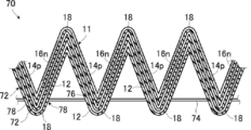
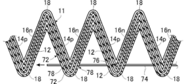
- thermoelectric conversion module 70 shown in FIG. 8 has two bellows-shaped thermoelectric conversion members 72 laminated on the support body 12 side of the module main body 11 so as to be uneven, and is stacked on the module main body 11 and the two thermoelectric conversion members 72.
- the wire 74 is inserted.
- the module main body 11 does not have the through-hole 28 and the reinforcement member 28a which are formed in a mountain fold part.
- the thermoelectric conversion module 70 is also referred to as “module 70”.
- the thermoelectric conversion member 72 has thermoelectric conversion layers that are formed on one surface of the support and are separated from each other, and connection electrodes that connect adjacent thermoelectric conversion layers.
- the thermoelectric conversion member 72 also performs power generation by thermoelectric conversion, like the module body 11. That is, the module main body 11 and the thermoelectric conversion member 72 are both accordion-shaped power generation modules that generate power by thermoelectric conversion.
- the thermoelectric conversion member 72 shown by FIG. 8 has the structure similar to the module main body 11 as a preferable aspect. That is, the thermoelectric conversion member 72 has alternately the P-type thermoelectric conversion layer 14p and the N-type thermoelectric conversion layer 16n having a certain length at regular intervals in the longitudinal direction of the long support 12.
- thermoelectric conversion member 72 has a connection electrode 18 that connects the adjacent P-type thermoelectric conversion layer 14p and the N-type thermoelectric conversion layer 16n, and alternates between a mountain fold and a valley fold at the longitudinal center of the connection electrode 18. It has a bellows-like shape folded back.
- through holes 76 are formed in the valley fold portions in the vicinity of both end portions in the width direction.
- the through hole 76 is formed in a reinforcing member similar to the reinforcing member 28a. Similar to the through-hole 28, as a preferred embodiment, the through-hole 76 is preferably formed in the width direction in the region where the connection electrode 18 and the P-type thermoelectric conversion layer 14 p and the N-type thermoelectric conversion layer 16 n in the width direction of the support 12 are formed. Located outside. Further, the through hole 28 is symmetrical in the longitudinal direction with respect to the center of the connection electrode 18 in the longitudinal direction (refer to the folded line indicated by a one-dot chain line in FIG.
- connection electrode 18 at the same position as the connection electrode 18 that is valley-folded.
- a pair is formed at the position.
- the through hole 76 is preferably formed at a position that is linear in the longitudinal direction when the support 12 is folded back in a bellows shape.
- thermoelectric conversion member 72 through holes 78 are formed in the valley folds in the vicinity of both end portions in the width direction of the inclined surface.
- the through hole 78 is also formed in the same reinforcing member as the reinforcing member 28a.
- the through hole 78 of the thermoelectric conversion member 72 is formed at the same position as the through hole 76 of the module body 11 in the width direction.
- a pair is formed at the valley fold portion at positions symmetrical to the folding line of the valley fold.
- the through-hole 78 is preferably formed at a position that is linear in the longitudinal direction when the thermoelectric conversion member 72 is folded back in a bellows shape.
- the through-hole 78 is preferably formed so as to be linear with the through-hole 76 of the module body 11 when the thermoelectric conversion member 72 is laminated on the module body 11.
- the module main body 11 and the two thermoelectric conversion members 72 are inserted by wires 74 through the through holes 76 of the module main body 11 and the through holes 78 of the thermoelectric conversion member 72. Therefore, in the module 70 as well as the module 10 described above, each member does not dissociate, and the bellows can be closed, and the interval between the bellows irregularities, that is, the interval between the bellows can be easily adjusted. Therefore, when mounting on a heat source having various shapes such as a curved surface, the mounting can be performed with good workability.
- the module 70 has a configuration in which three accordion-shaped power generation modules that generate power substantially by thermoelectric conversion are stacked, so that a large amount of power generation can be obtained. Furthermore, since the thermoelectric conversion layer of the module main body 11 and the thermoelectric conversion member 72 is laminated facing the support 12 of another member, it is possible to prevent a short circuit of the thermoelectric conversion layer when the bellows is closed.
- thermoelectric conversion member 72 is a single bellows-shaped power generation module that generates power by thermoelectric conversion.
- the thermoelectric conversion member 72 has the same structure as the module main body 11.
- any accordion-shaped power generation module can be regarded as a module body in the thermoelectric conversion module of the present invention.
- any one of the bellows-shaped power generation modules of the thermoelectric conversion member 72 and the module main body 11 may be regarded as the module main body in the present invention.
- the module 70 shown in FIG. 8 includes the module body 11 and the thermoelectric conversion member 72 laminated on the support 12 of the module body 11 with the thermoelectric conversion layer (member thermoelectric conversion layer) facing each other.
- the thermoelectric conversion member 72 is laminated on the support 12 (member support) of the thermoelectric conversion member 72 so as to face the thermoelectric conversion layer (module main body 11 / thermoelectric conversion member 72 / thermoelectric conversion). Configuration of member 72).
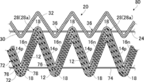
- the module 70 shown in FIG. 8 is supported by the module main body 11, the thermoelectric conversion member 72 laminated on the support body 12 of the module main body 11 so as to face the thermoelectric conversion layer, and the thermoelectric conversion layer of the module main body 11.
- thermoelectric conversion member 72 laminated facing the body 12 (configuration of thermoelectric conversion member 72 / module body 11 / thermoelectric conversion member 72).
- the module 70 includes a module main body 11, a thermoelectric conversion member 72 laminated on the thermoelectric conversion layer of the module main body 11 so as to face the support 12, and a thermoelectric conversion layer on the support 12 of the thermoelectric conversion member 72.
- a single module may be regarded as a module body in the present invention.
- the thermoelectric conversion module of the present invention has a single bellows-shaped power generation module having the same configuration as the module main body 84 shown in FIG.
- the module main body 84 may have the same configuration as the module main body in the present invention, and the module main body 11 may have the same configuration as the thermoelectric conversion member in the present invention.
- thermoelectric conversion module of the present invention may have a configuration in which two accordion-shaped power generation modules each having only one thermoelectric conversion member 72 are stacked.
- the thermoelectric conversion member 72 may be stacked on the thermoelectric conversion layer side of the module body 11 or may be stacked on the support 12 side.
- unit which has the thermoelectric conversion member 72 3 or more may be sufficient.
- the module main body 11 and the thermoelectric conversion member 72 have the same configuration.
- the present invention is not limited to this. That is, in the present invention, in the configuration having the thermoelectric conversion member as the bellows-like member, the shape and / or position of the thermoelectric conversion layer, the shape and / or position of the connection electrode, and the thermoelectric conversion layer of the module body and the thermoelectric conversion member
- the types (both P-type and N-type, only P-type, only N-type) and the like may be different (see FIGS. 10 and 11 described later). That is, the configuration may be different between the module body and the thermoelectric conversion member.
- a structure may differ between thermoelectric conversion members.
- any bellows-shaped power generation module alone may be regarded as the module body in the present invention.
- a plurality of bellows-like shapes are possible in that the bellows-like shape can be folded back in a state where the module main body 11 and the thermoelectric conversion member 72 are laminated.
- thermoelectric conversion module of the present invention may have the insulating member 20 and / or the heat radiating member 42 even in such a configuration having one or more bellows-like thermoelectric conversion members.
- the insulating member 20 may be provided in the module 70 shown in FIG. 8 similarly to the module 10 shown in FIGS. 1A to 1C.
- the thermoelectric conversion module shown in FIG. 5 the thermoelectric conversion module shown in FIG. May be laminated. 1A to 1C
- a thermoelectric conversion member 72 may be provided on the insulating member 20.
- the module body 11, the thermoelectric conversion member 72, and the thermoelectric conversion members 72 are laminated with the support 12 and the thermoelectric conversion layer facing each other.
- the thermoelectric conversion member 72 when the module main body 11 and the thermoelectric conversion member 72 have the same configuration, the thermoelectric conversion member 72 is turned upside down, the thermoelectric conversion layers face each other, and the module main body 11 and The thermoelectric conversion member 72 may be laminated.
- the mountain fold and the valley fold in the alternate long and short dash line are reversed.
- the module main body 11 is provided with the P-type thermoelectric conversion layer 14p and the N-type thermoelectric conversion layer 16n alternately on the inclined surface on one surface of the support 12 folded in a bellows shape and adjacent to each other.
- the P-type thermoelectric conversion layer 14p and the N-type thermoelectric conversion layer 16n are connected by the connection electrode 18 straddling adjacent inclined surfaces, the present invention is not limited to this, and various configurations can be used. is there.
- the module main body thermoelectric conversion member
- the module main body may be provided with a P-type thermoelectric conversion layer 14p and an N-type thermoelectric conversion layer 16n on one inclined surface of the support body 12 folded in a bellows shape so as to be separated from each other. .
- module main body 84 shown in FIG. 10 uses many of the same members as those of the module main body 11 shown in FIG. 2 and the like, the same reference numerals are given to the same members, and the following description mainly focuses on differences. To do. The same applies to the module main body 95 shown in FIG. Moreover, these module main bodies can be used also as a thermoelectric conversion member.
- FIG. 10 is a conceptual diagram in which the module main body 84 is extended in a planar shape as in FIG.
- the mountain folds and the valley folds of the support 12 are alternately performed by a one-dot chain line. That is, the space between the alternate long and short dash lines is the inclined surface of the support 12 that is folded back in a bellows shape.
- 10 includes an inclined surface having a P-type thermoelectric conversion layer 86p, an N-type thermoelectric conversion layer 90n, and a P-type thermoelectric conversion layer 86p that are separated from each other, and an N-type thermoelectric conversion layer 90n and a P-type that are separated from each other.
- the inclined surfaces having the thermoelectric conversion layers 86p and the N-type thermoelectric conversion layers 90n are alternately provided in the longitudinal direction.
- thermoelectric conversion layer 86p In the inclined surface having the P-type thermoelectric conversion layer 86p, the N-type thermoelectric conversion layer 90n, and the P-type thermoelectric conversion layer 86p, the two P-type thermoelectric conversion layers 86p sandwich the N-type thermoelectric conversion layer 90n in the width direction. A thermoelectric conversion layer is disposed. On this inclined surface, the P-type thermoelectric conversion layer 86p, the N-type thermoelectric conversion layer 90n, and the P-type thermoelectric conversion layer 86p are connected in series by two connection electrodes 94.
- connection electrode 94 connects one P-type thermoelectric conversion layer 86p and the N-type thermoelectric conversion layer 90n so as to sandwich the N-type thermoelectric conversion layer 90n in the longitudinal direction, and the N-type thermoelectric conversion layer 90n and the other P-type thermoelectric conversion layer 90n.
- the conversion layer 86p is connected.
- the two N-type thermoelectric conversion layers 90n sandwich the P-type thermoelectric conversion layer 86p in the width direction.
- a thermoelectric conversion layer is disposed.
- the N-type thermoelectric conversion layer 90n and the P-type thermoelectric conversion layer 86p are connected by the connection electrode 92 straddling the ridge line of the inclined surface.
- the connection between the N-type thermoelectric conversion layer 90n and the P-type thermoelectric conversion layer 86p on the adjacent inclined surfaces by the connection electrode 92 is alternately performed in the thermoelectric conversion layer at the end in the width direction. Thereby, all the P-type thermoelectric conversion layers 86p and N-type thermoelectric conversion layers 90n formed on the support 12 are alternately connected in series.
- the module body has both an N-type thermoelectric conversion layer and a P-type thermoelectric conversion layer, but the present invention is not limited to this, and the module body (thermoelectric conversion member) A configuration having only an N-type thermoelectric conversion layer or a P-type thermoelectric conversion layer may be used. An example is shown in FIG.
- connection electrode 96 On the inclined surface having the two P-type thermoelectric conversion layers 86p in the vicinity of the end in the width direction, the two P-type thermoelectric conversion layers 86p are connected by the connection electrode 96.
- the connection of the P-type thermoelectric conversion layer 86p by the connection electrode 96 is performed at the ends of the two P-type thermoelectric conversion layers 86p on the opposite side in the longitudinal direction.
- the connection electrode 92 straddling the ridgeline of the inclined surface is connected to the two P-type thermoelectric conversion layers 86p.
- the connection electrodes 92 connected to each P-type thermoelectric conversion layer 86p reach different inclined surfaces.
- the module body has the thermoelectric conversion layer only on one surface of the support, but the present invention is not limited to this. That is, in the thermoelectric conversion module of the present invention, the module body (thermoelectric conversion member) may have thermoelectric conversion layers on both sides of the support.
- thermoelectric conversion member has a thermoelectric conversion member and the thermoelectric conversion layer of the module body and the thermoelectric conversion layer of the thermoelectric conversion member face each other, or the thermoelectric conversion between the thermoelectric conversion members
- a bellows-like insulating member made of only an insulating material may be provided between the module body and the thermoelectric conversion layer, or the thermoelectric power of the module body and / or the thermoelectric conversion layer may be provided.
- the conversion layer may be covered with an insulating film.
- FIG. 12 an example of the heat conductive laminated body of this invention is shown notionally.
- a heat conductive laminated body 56 shown in FIG. 12 is formed by laminating the above-described insulating member 20 and the heat radiating member 42 together with the bellows unevenness, and penetrates the through hole of the insulating member 20 and the through hole 50 of the heat radiating member. Then, the insulating member 20 and the heat radiating member 42 are inserted through the wire 46. That is, the heat conductive laminate 56 is obtained by removing the module main body 11 from the module 10 shown in FIG. 4A.
- the module 10 shown in FIG. 4A is a combination of the module main body 11 and the heat conductive laminate 56 shown in FIG.
- the insulating member 20 is obtained by forming the heat conductive layer 32 on one surface of the support 30 as a preferred embodiment.
- the thermally conductive laminate 56 of the present invention is not limited to this, and the insulating member 20 is formed by folding an insulating sheet-like material such as a resin film into a bellows shape. Only the structure may be sufficient.
- a long bellows-like insulating member 20 in which the wire 60 is inserted through the through hole 36 is produced.
- the module main body 11 through which the wire 24 is inserted and the insulating member 20 through which the wire 60 is inserted are conveyed in the longitudinal direction, and the conveyance path of the module main body 11 is bent by 90 ° by a roller 62. Similarly, the conveyance path of the insulating member 20 is bent 90 ° by the roller 64.
- the module body 11 and the insulating member 20 are transported at the time when the transport path is bent by the rollers 62 and 64, the thermoelectric conversion layer forming surface of the module body 11, the support 30 of the insulating member 20, and the like. Do so as to face each other. As shown in FIGS.
- the module main body 11 and the insulating member 20 are laminated together with the bellows unevenness at a place where the module main body 11 and the insulating member 20 are bent by 90 °, that is, a place where the conveyance path is changed. .
- At least one of the transport paths is changed while transporting the long bellows-like module body 11 and the insulating member 20 in the longitudinal direction, and the module body 11 and the insulating member 20 are changed at the change point of the transport path.
- the module main body 11 is conveyed in the state where the wire 24 and the insulating member 20 are respectively inserted through the wire 60, even if conveyance in the longitudinal direction, change of the conveyance path and lamination are performed, an appropriate bellows The shape can be maintained. Therefore, it is possible to stably stack the proper module body 11 and the insulating member 20 with the unevenness.
- the wire 24 from the module main body 11 and the wire 60 from the insulating member 20 are respectively connected. Pull out.
- the module body 11 and the insulating member 20 are aligned.
- the module main body 11 and the insulating member 20 are aligned so that the through holes 28 of the module main body 11 and the through holes of the insulating member 20 are linearly arranged.
- the wire 24 pulled out from the module body 11 is inserted so as to penetrate the through hole 28 of the module body 11 and the through hole of the insulating member 20.
- the long bellows-like module main body 11 and the insulating member 20 are combined with the irregularities of the bellows, and the module 10 of the present invention is inserted through the wire 24. Therefore, in this example, the wire 24 pulled out from the module main body 11 becomes a fixing linear member.
- the wire 60 drawn from the insulating member 20 may be used as the fixing linear member.
- the wire 24 and the wire 60 are pulled out and aligned, and then the wire 24 is inserted again.
- the module body 11 and the insulating member 20 are connected with another wire without pulling out the wire 24 and the wire 60. Insert.
- thermoelectric conversion module shown in FIGS. It can be manufactured by repeating.
- the heat conductive laminate 56 shown in FIG. 12 can be similarly manufactured using the bellows-like insulating member 20 through which the linear member is inserted and the bellows-shaped heat dissipation member 42 through which the linear member is inserted.
- the module 40 shown in FIG. 4A may be manufactured in the same manner using the heat conductive laminate 56 shown in FIG. 12 and the module main body 11 inserted with the wire 24 shown in FIG. In this case, a wire may be inserted separately at a position corresponding to the through hole 36 of the insulating member 20.
- a thermoelectric conversion module in which the module main bodies 11 are laminated can be manufactured by regarding one or more module main bodies different from the module main bodies 11 as bellows-like members.
- the laminate is bent into a bellows shape.
- a method of folding the laminated body into a bellows shape various known methods for folding a sheet-like material or a laminated body of sheet-like materials into a bellows shape, such as a method of inserting between gears that mesh with each other, can be used. .
- thermoelectric conversion member 72, the thermoelectric conversion member 72, and the inclined surface of the module main body 11 bent in a bellows shape are penetrated to the thermoelectric conversion member 72, the thermoelectric conversion member 72, and the module main body 11.
- the wire 74 By inserting the wire 74, a module 70 as shown in FIG. 8 is obtained.
- the through hole 76 of the module main body 11 that penetrates the wire 74 and the through hole 78 of the thermoelectric conversion member 72 may be formed in a state before being bent into the bellows shape shown in FIG. 17A, and the laminate shown in FIG. 17B. May be formed at the stage of bending the bellows into a bellows shape.
- the through hole 76 and the through hole 78 may be formed by inserting the wire 74 after being bent into a bellows shape.
- the insulating member as shown in FIG. 9 is obtained by carrying out the first aspect of the manufacturing method of the present invention as shown in FIGS. 13 to 16B.
- a module 80 having 20 or the like can also be manufactured.
- thermoelectric conversion module and the heat conductive laminate of the present invention and the method of manufacturing the thermoelectric conversion module and the method of manufacturing the heat conductive laminate have been described, but the present invention is not limited to the above-described examples, Of course, various improvements and modifications may be made without departing from the scope of the present invention.
Landscapes
- Cooling Or The Like Of Semiconductors Or Solid State Devices (AREA)
Abstract
蛇腹状の熱電変換モジュールにおいて、絶縁部材や放熱部材等を組み合わせて、良好な構成の安定性や取り扱い性を有し、可撓性も良好な熱電変換モジュール、この熱電変換モジュールに用いられる熱伝導性積層体、ならびに、その製造方法の提供を課題とする。蛇腹状の支持体と、支持体に形成される互いに離間する熱電変換層と、隣接する熱電変換層を接続する接続電極と、を有するモジュール本体; モジュール本体と凹凸を合わせて設けられる1以上の蛇腹状部材; モジュール本体の蛇腹の傾斜面と、1以上の蛇腹状部材の蛇腹状の傾斜面とを貫通して、モジュール本体と1以上の蛇腹状部材とを挿通する可撓性の線状部材; を有することにより、課題を解決する。
Description
本発明は、生産性が良好な熱電変換モジュール、および、この熱電変換モジュールの製造方法、ならびに熱電変換モジュールなどに利用される熱伝導性積層体に関する。
熱エネルギーと電気エネルギーとを相互に変換することができる熱電変換材料が、熱によって発電する発電素子やペルチェ素子のような熱電変換素子に用いられている。
熱電変換素子は、熱エネルギーを直接電力に変換することができ、可動部を必要としない等の利点を有する。そのため、複数の熱電変換素子を接続してなる熱電変換モジュール(発電装置)は、例えば、焼却炉や工場の各種の設備など、排熱される部位に設けることで、動作コストを掛ける必要なく、簡易に電力を得ることができる。
熱電変換素子は、熱エネルギーを直接電力に変換することができ、可動部を必要としない等の利点を有する。そのため、複数の熱電変換素子を接続してなる熱電変換モジュール(発電装置)は、例えば、焼却炉や工場の各種の設備など、排熱される部位に設けることで、動作コストを掛ける必要なく、簡易に電力を得ることができる。
熱電変換素子は、通常、複数を直列に接続した熱電変換モジュールとして使用される。熱電変換モジュールとしては、Bi-Te等の熱電変換材料等を用いた、いわゆるπ型の熱電変換モジュールが知られている。
π型の熱電変換モジュールは、一例として、P型およびN型の熱電変換材料をブロック状に加工して、セラミックス等の基板の上に交互に配列し、配列した熱電変換材料を直列に接続することで、作製される。
π型の熱電変換モジュールは、一例として、P型およびN型の熱電変換材料をブロック状に加工して、セラミックス等の基板の上に交互に配列し、配列した熱電変換材料を直列に接続することで、作製される。
このようなπ型の熱電変換モジュールは、ブロック状の熱電変換材料の加工、熱電変換材料の配列、電極による熱電変換材料の接続等に手間がかかる。
これに対して、樹脂フィルム等の可撓性を有する絶縁性の支持体(基板)上に、印刷などの塗布法や真空蒸着などの真空成膜法によって熱電変換層および電極を形成した熱電変換モジュールが報告されている。
これに対して、樹脂フィルム等の可撓性を有する絶縁性の支持体(基板)上に、印刷などの塗布法や真空蒸着などの真空成膜法によって熱電変換層および電極を形成した熱電変換モジュールが報告されている。
例えば、特許文献1には、蛇腹状(波形状)に折り返すことで表面側に突出する複数の頂部および裏面側に突出する複数の底部が形成された、可撓性を有する絶縁性シートと、絶縁性シートに設けられた第1接点および第2接点を有する熱電対とからなり、第1接点を頂部に隣接する頂部隣接部に配置し、第2接点を底部に隣接する底部隣接部に配置した熱電変換モジュールが記載されている。
また、特許文献2には、頂部および底部が交互に繰り返される蛇腹状(波形状構造)に折り返された可撓性基材と、基材に形成される、頂部と頂部につながる第1の底部との間の第1の傾斜面に沿った第1の熱電変換層と、頂部と頂部につながる第2の底部との間の第2の傾斜面に沿った第2の熱電変換層とを有し、第1の熱電変換層と第2の熱電変換層とが同じ形を有し、第1の熱電変換層は頂部側と第1の底部側に、第2の熱電変換層は頂部側と第2の底部側に、それぞれ、配線との接続点を有する熱電変換モジュールが記載されている。
このような樹脂フィルム等を支持体として用いる熱電変換モジュールにおいては、インク状の熱電変換材料や電極材料を用いる塗布法や、熱電変換材料や電極材料を真空蒸着等の真空成膜法によって、熱電変換層や電極を形成できる。
そのため、この熱電変換モジュールは、ブロック状の熱電変換材料を用いるπ型の熱電変換モジュールに比して、製造が容易であり、製造コストも安くできる。
また、熱電変換素子は、一つ当たりの起電力が非常に小さいため、熱電変換モジュールは、数百以上の熱電変換素子を直列に接続して、電圧および発電量を増加させる必要が有る。これに対して、樹脂フィルム等を支持体として用いる熱電変換モジュールであれば、多数個の熱電変換素子の形成にも、印刷等での製造によって容易に対応できる。
そのため、この熱電変換モジュールは、ブロック状の熱電変換材料を用いるπ型の熱電変換モジュールに比して、製造が容易であり、製造コストも安くできる。
また、熱電変換素子は、一つ当たりの起電力が非常に小さいため、熱電変換モジュールは、数百以上の熱電変換素子を直列に接続して、電圧および発電量を増加させる必要が有る。これに対して、樹脂フィルム等を支持体として用いる熱電変換モジュールであれば、多数個の熱電変換素子の形成にも、印刷等での製造によって容易に対応できる。
このような、可撓性を有する蛇腹状の熱電変換モジュールの発電量等の性能を向上する方法としては、各種の方法が考えられる。
例えば、特許文献1および特許文献2にも示されるように、従来の蛇腹状に折り返した形状を有する熱電変換モジュールは、熱電変換層等が形成される蛇腹の傾斜面は、対面する傾斜面と離間した状態となっている。
しかしながら、このような蛇腹状の熱電変換モジュールは、サイズを小型化できる、伝熱効率を向上できる、熱電変換素子の実装密度を向上できる等の点で、蛇腹状に折り返した支持体を熱電変換層の配列方向に圧縮して、可能な限り蛇腹を閉じた状態とした方が有利である。
ところが、従来の蛇腹状の熱電変換モジュールでは、蛇腹を閉じると、電極同士が接触して、短絡してしまい、全く発電しなくなってしまう。そのため、蛇腹状の熱電変換モジュールに、絶縁部材を組み合わせることが考えられる。
しかしながら、このような蛇腹状の熱電変換モジュールは、サイズを小型化できる、伝熱効率を向上できる、熱電変換素子の実装密度を向上できる等の点で、蛇腹状に折り返した支持体を熱電変換層の配列方向に圧縮して、可能な限り蛇腹を閉じた状態とした方が有利である。
ところが、従来の蛇腹状の熱電変換モジュールでは、蛇腹を閉じると、電極同士が接触して、短絡してしまい、全く発電しなくなってしまう。そのため、蛇腹状の熱電変換モジュールに、絶縁部材を組み合わせることが考えられる。
また、熱電変換モジュールは、放熱フィン等を併用することで熱電変換層の温度差を大きくして、発電量を向上できることが知られている。
従って、発電量の向上を目的として、蛇腹状の熱電変換モジュールにも、放熱フィン等と同様の放熱部材を組み合わせることが考えられる。
従って、発電量の向上を目的として、蛇腹状の熱電変換モジュールにも、放熱フィン等と同様の放熱部材を組み合わせることが考えられる。
このように、蛇腹状の熱電変換モジュールに絶縁部材や放熱部材を組み合わせた場合には、熱電変換モジュールと部材とが解離することなく構成を安定的に保ち、取り扱い性が良好なことが要求される。
また、可撓性を有する蛇腹状の熱電変換モジュールでは、可撓性を生かして、円筒状の管などの曲面に装着されることが考えられる。従って、蛇腹状の熱電変換モジュールには、絶縁部材や放熱部材を組み合わされた場合でも、可撓性を有するのが好ましい。
また、可撓性を有する蛇腹状の熱電変換モジュールでは、可撓性を生かして、円筒状の管などの曲面に装着されることが考えられる。従って、蛇腹状の熱電変換モジュールには、絶縁部材や放熱部材を組み合わされた場合でも、可撓性を有するのが好ましい。
しかしながら、現状では、このような可撓性を有する蛇腹状の熱電変換モジュールに、絶縁部材や放熱部材等を組み合わせて、尚且つ、良好な構成の安定性や取り扱い性、可撓性等を満たした熱電変換モジュールは、知られていない。
本発明の目的は、このような従来技術の問題点を解決することにあり、可撓性を有する蛇腹状の熱電変換モジュールに、絶縁部材や放熱部材等を組み合わせて、さらに、良好な構成の安定性や取り扱い性を有し、可撓性も良好な熱電変換モジュール、および、この熱電変換モジュールに利用される熱伝導性積層体、ならびに、これらの製造方法を提供することにある。
このような目的を達成するために、本発明の熱電変換モジュールは、蛇腹状に折り返された支持体と、支持体の少なくとも一方の面に形成される、互いに離間する複数の熱電変換層と、隣接する熱電変換層を接続する接続電極と、を有するモジュール本体、
モジュール本体と凹凸を合わせて設けられる、蛇腹状に折り返された1以上の蛇腹状部材、および、
モジュール本体の蛇腹状の折り返しによる傾斜面と、少なくとも1つの蛇腹状部材の蛇腹状の折り返しによる傾斜面とを貫通して、モジュール本体と少なくとも1つの蛇腹状部材とを挿通する可撓性の線状部材、を有することを特徴とする熱電変換モジュールを提供する。
モジュール本体と凹凸を合わせて設けられる、蛇腹状に折り返された1以上の蛇腹状部材、および、
モジュール本体の蛇腹状の折り返しによる傾斜面と、少なくとも1つの蛇腹状部材の蛇腹状の折り返しによる傾斜面とを貫通して、モジュール本体と少なくとも1つの蛇腹状部材とを挿通する可撓性の線状部材、を有することを特徴とする熱電変換モジュールを提供する。
このような本発明の熱電変換モジュールにおいて、蛇腹状部材が、絶縁部材、放熱部材および熱電変換部材から選択される1以上であるのが好ましい。
また、モジュール本体の熱電変換層の形成面に対面して、絶縁部材が設けられるのが好ましい。
また、絶縁部材のモジュール本体とは逆側の面に対面して、放熱部材が設けられるのが好ましい。
また、絶縁部材の傾斜面と、放熱部材の傾斜面とを貫通して、絶縁部材と放熱部材とを挿通する可撓性の第2線状部材を有するのが好ましい。
また、絶縁部材が、絶縁層の表面に熱伝導性層を有するものであり、絶縁層をモジュール本体の熱電変換層の形成面に向けて設けられるのが好ましい。
また、熱電変換部材が、蛇腹状に折り返された部材支持体と、部材支持体の少なくとも一方の面に形成される、互いに離間する複数の部材熱電変換層と、隣接する熱電変換層を接続する部材接続電極と、を有するのが好ましい。
また、モジュール本体が、支持体の一方の面のみに熱電変換層を有するものであり、熱電変換部材が、部材支持体の一方の面にのみに部材熱電変換層を有するものであり、モジュール本体の熱電変換層に、部材支持体を対面して設けられる熱電変換部材、および、モジュール本体の支持体に、部材熱電変換層を対面して設けられる熱電変換部材の、少なくも一方を有するのが好ましい。
また、熱電変換部材を、複数、有し、部材支持体と部材熱電変換層とを対面して設けられる熱電変換部材の組み合わせを、1以上、有するのが好ましい。
また、線状部材が、モジュール本体の、熱電変換層の形成位置および接続電極の形成位置、以外の場所を貫通するのが好ましい。
また、線状部材が、接続電極に対して、傾斜面の傾斜方向に同位置で、かつ、稜線の長手方向の外側を貫通するのが好ましい。
さらに、モジュール本体の熱電変換層が、支持体の一方の面において、傾斜面に一面ずつ交互に設けられるP型熱電変換層およびN型熱電変換層であるのが好ましい。
また、モジュール本体の熱電変換層の形成面に対面して、絶縁部材が設けられるのが好ましい。
また、絶縁部材のモジュール本体とは逆側の面に対面して、放熱部材が設けられるのが好ましい。
また、絶縁部材の傾斜面と、放熱部材の傾斜面とを貫通して、絶縁部材と放熱部材とを挿通する可撓性の第2線状部材を有するのが好ましい。
また、絶縁部材が、絶縁層の表面に熱伝導性層を有するものであり、絶縁層をモジュール本体の熱電変換層の形成面に向けて設けられるのが好ましい。
また、熱電変換部材が、蛇腹状に折り返された部材支持体と、部材支持体の少なくとも一方の面に形成される、互いに離間する複数の部材熱電変換層と、隣接する熱電変換層を接続する部材接続電極と、を有するのが好ましい。
また、モジュール本体が、支持体の一方の面のみに熱電変換層を有するものであり、熱電変換部材が、部材支持体の一方の面にのみに部材熱電変換層を有するものであり、モジュール本体の熱電変換層に、部材支持体を対面して設けられる熱電変換部材、および、モジュール本体の支持体に、部材熱電変換層を対面して設けられる熱電変換部材の、少なくも一方を有するのが好ましい。
また、熱電変換部材を、複数、有し、部材支持体と部材熱電変換層とを対面して設けられる熱電変換部材の組み合わせを、1以上、有するのが好ましい。
また、線状部材が、モジュール本体の、熱電変換層の形成位置および接続電極の形成位置、以外の場所を貫通するのが好ましい。
また、線状部材が、接続電極に対して、傾斜面の傾斜方向に同位置で、かつ、稜線の長手方向の外側を貫通するのが好ましい。
さらに、モジュール本体の熱電変換層が、支持体の一方の面において、傾斜面に一面ずつ交互に設けられるP型熱電変換層およびN型熱電変換層であるのが好ましい。
また、本発明の熱伝導性積層体は、蛇腹状に折り返された絶縁部材、
絶縁部材と凹凸を合わせて設けられる、蛇腹状に折り返された放熱部材、および、
絶縁部材の蛇腹状の折り返しによる傾斜面と、放熱部材の蛇腹状の折り返しによる傾斜面とを貫通して、絶縁部材と放熱部材とを挿通する可撓性の線状部材、を有することを特徴とする熱伝導性積層体を提供する。
絶縁部材と凹凸を合わせて設けられる、蛇腹状に折り返された放熱部材、および、
絶縁部材の蛇腹状の折り返しによる傾斜面と、放熱部材の蛇腹状の折り返しによる傾斜面とを貫通して、絶縁部材と放熱部材とを挿通する可撓性の線状部材、を有することを特徴とする熱伝導性積層体を提供する。
このような本発明の熱伝導性積層体において、絶縁部材が、絶縁層の表面に熱伝導性層を有するものであるのが好ましい。
また、本発明の熱電変換モジュールの製造方法の第1の態様は、蛇腹状に折り返された支持体と、支持体の少なくとも一方の面に形成される、互いに離間する複数の熱電変換層と、隣接する熱電変換層を接続する接続電極と、蛇腹状の折り返しによる傾斜面を貫通して蛇腹を挿通する可撓性の線状部材と、を有するモジュール本体を作製する工程、
蛇腹状に折り返され、蛇腹状の折り返しによる傾斜面を貫通して蛇腹を挿通する可撓性の線状部材を有する、蛇腹状部材を作製する工程、
モジュール本体と蛇腹状部材とを、蛇腹状の折り返しによる稜線と直交する方向に搬送しつつ、搬送経路に設けられた搬送経路の変更部において、凹凸を合わせて積層する工程、および、
モジュール本体の傾斜面と蛇腹状部材の傾斜面とを貫通して、積層したモジュール本体と蛇腹状部材とを挿通する可撓性の固定用線状部材を設ける工程、を有することを特徴とする熱電変換モジュールの製造方法を提供する。
蛇腹状に折り返され、蛇腹状の折り返しによる傾斜面を貫通して蛇腹を挿通する可撓性の線状部材を有する、蛇腹状部材を作製する工程、
モジュール本体と蛇腹状部材とを、蛇腹状の折り返しによる稜線と直交する方向に搬送しつつ、搬送経路に設けられた搬送経路の変更部において、凹凸を合わせて積層する工程、および、
モジュール本体の傾斜面と蛇腹状部材の傾斜面とを貫通して、積層したモジュール本体と蛇腹状部材とを挿通する可撓性の固定用線状部材を設ける工程、を有することを特徴とする熱電変換モジュールの製造方法を提供する。
このような本発明の熱電変換モジュールの製造方法の第1の態様において、固定用線状部材が、モジュール本体を挿通する線状部材および蛇腹状部材を挿通する線状部材の少なくとも一方であり、固定用線状部材を挿通する工程では、積層したモジュール本体および蛇腹状部材から線状部材を引き抜く工程、モジュール本体と蛇腹状部材との位置合わせを行う工程、ならびに、線状部材を抜いた斜面の貫通孔に、モジュール本体から引き抜いた線状部材および蛇腹状部材から引き抜いた線状部材の少なくとも一方を挿通する工程、を行うのが好ましい。
また、固定用線状部材を挿通する工程では、モジュール本体を挿通する線状部材および蛇腹状部材を挿通する線状部材をそのままにして、モジュール本体と蛇腹状部材とに固定用線状部材を挿通するのが好ましい。
また、蛇腹状部材が、絶縁部材、放熱部材および熱電変換部材から選択される1以上であるのが好ましい。
また、絶縁部材と放熱部材とを凹凸を合わせて積層し、かつ、絶縁部材の傾斜面と放熱部材の傾斜面とを貫通して、絶縁部材と放熱部材とを挿通する可撓性の線状部材を設けるのが好ましい。
さらに、絶縁部材が、絶縁層の表面に熱伝導性層を有するものであるのが好ましい。
また、固定用線状部材を挿通する工程では、モジュール本体を挿通する線状部材および蛇腹状部材を挿通する線状部材をそのままにして、モジュール本体と蛇腹状部材とに固定用線状部材を挿通するのが好ましい。
また、蛇腹状部材が、絶縁部材、放熱部材および熱電変換部材から選択される1以上であるのが好ましい。
また、絶縁部材と放熱部材とを凹凸を合わせて積層し、かつ、絶縁部材の傾斜面と放熱部材の傾斜面とを貫通して、絶縁部材と放熱部材とを挿通する可撓性の線状部材を設けるのが好ましい。
さらに、絶縁部材が、絶縁層の表面に熱伝導性層を有するものであるのが好ましい。
また、本発明の熱電変換モジュールの製造方法の第2の態様は、支持体と、支持体の少なくとも一方の面に形成される互いに離間する複数の熱電変換層と、隣接する熱電変換層を接続する接続電極と、を有するシート状物を、複数枚、積層する工程、
シート状物の積層体を、蛇腹状に折り返す工程、および、
蛇腹状に折り返したシート状物の、蛇腹状の折り返しによる傾斜面を貫通して、可撓性の線状部材を挿通する工程、を有することを特徴とする熱電変換モジュールの製造方法を提供する。
シート状物の積層体を、蛇腹状に折り返す工程、および、
蛇腹状に折り返したシート状物の、蛇腹状の折り返しによる傾斜面を貫通して、可撓性の線状部材を挿通する工程、を有することを特徴とする熱電変換モジュールの製造方法を提供する。
さらに、本発明の熱伝導性積層体の製造方法は、蛇腹状に折り返され、蛇腹状の折り返しによる傾斜面を貫通して蛇腹を挿通する可撓性の線状部材を有する、絶縁部材を作製する工程、
蛇腹状に折り返され、蛇腹状の折り返しによる傾斜面を貫通して蛇腹を挿通する可撓性の線状部材を有する、放熱部材を作製する工程、
絶縁部材と放熱部材とを、蛇腹状の折り返しによる稜線と直交する方向に搬送しつつ、搬送経路に設けられた搬送経路の変更部において、凹凸を合わせて絶縁部材と放熱部材とを積層する工程、ならびに、
積層した絶縁部材および放熱部材の傾斜面を貫通して、可撓性の固定用線状部材を挿通する工程、を有することを特徴とする熱伝導性積層体の製造方法を提供する。
蛇腹状に折り返され、蛇腹状の折り返しによる傾斜面を貫通して蛇腹を挿通する可撓性の線状部材を有する、放熱部材を作製する工程、
絶縁部材と放熱部材とを、蛇腹状の折り返しによる稜線と直交する方向に搬送しつつ、搬送経路に設けられた搬送経路の変更部において、凹凸を合わせて絶縁部材と放熱部材とを積層する工程、ならびに、
積層した絶縁部材および放熱部材の傾斜面を貫通して、可撓性の固定用線状部材を挿通する工程、を有することを特徴とする熱伝導性積層体の製造方法を提供する。
このような本発明の熱伝導性積層体の製造方法において、固定用線状部材が、絶縁部材の傾斜面を挿通する線状部材および放熱部材の傾斜面を挿通する線状部材の少なくとも一方であり、固定用線状部材を挿通する工程では、積層した絶縁部材および放熱部材から線状部材を引き抜く工程、絶縁部材と放熱部材との位置合わせを行う工程、ならびに、線状部材を抜いた斜面の貫通孔に、絶縁部材から引き抜いた線状部材および放熱部材から引き抜いた線状部材の少なくとも一方を挿通する工程、を行うのが好ましい。
また、固定用線状部材を挿通する工程では、絶縁部材を挿通する線状部材および放熱部材を挿通する線状部材をそのままにして、絶縁部材と放熱部材とに固定用線状部材を挿通するのが好ましい。
さらに、絶縁部材が、絶縁層の表面に熱伝導性層を有するものであるのが好ましい。
また、固定用線状部材を挿通する工程では、絶縁部材を挿通する線状部材および放熱部材を挿通する線状部材をそのままにして、絶縁部材と放熱部材とに固定用線状部材を挿通するのが好ましい。
さらに、絶縁部材が、絶縁層の表面に熱伝導性層を有するものであるのが好ましい。
このような本発明によれば、可撓性を有する蛇腹状の熱電変換モジュールに、絶縁部材や放熱部材等を組み合わせ、さらに、良好な構成の安定性や取り扱い性を有し、可撓性も良好な熱電変換モジュールが得られる。
以下、本発明の熱電変換モジュールおよび熱伝導性積層体、ならびに、熱電変換モジュールの製造方法および熱伝導性積層体の製造方法について、添付の図面に示される好適実施例を基に詳細に説明する。
なお、本明細書において、『~』を用いて表される数値範囲は、『~』の前後に記載される数値を下限値および上限値として含む範囲を意味する。
なお、本明細書において、『~』を用いて表される数値範囲は、『~』の前後に記載される数値を下限値および上限値として含む範囲を意味する。
図1A~図1Cに、本発明の熱電変換モジュールの一例を概念的に示す。
図1Aは概略正面図、図1Bは概略斜視図、図1Cは熱電変換モジュール10の蛇腹を閉じた状態を示す概略正面図である。
図1Aは概略正面図、図1Bは概略斜視図、図1Cは熱電変換モジュール10の蛇腹を閉じた状態を示す概略正面図である。
なお、正面図とは、本発明の熱電変換モジュール10をモジュール本体11の面方向に見た図である。
また、図1Cでは、熱電変換モジュール10の構成や各部材が明瞭に示せるように、蛇腹状の折り返し部を矩形状にして示している。しかしながら、本発明の熱電変換モジュール10において、蛇腹を閉じた状態は、図1Aに示す熱電変換モジュール10を図中横方向に圧縮した状態である。従って、熱電変換モジュール10の蛇腹を閉じた状態では、後述する山折りおよび谷折りされた折り返し部は、鋭角状になる。この点に関しては、後述する図4Bも同様である。
また、図1Cでは、熱電変換モジュール10の構成や各部材が明瞭に示せるように、蛇腹状の折り返し部を矩形状にして示している。しかしながら、本発明の熱電変換モジュール10において、蛇腹を閉じた状態は、図1Aに示す熱電変換モジュール10を図中横方向に圧縮した状態である。従って、熱電変換モジュール10の蛇腹を閉じた状態では、後述する山折りおよび谷折りされた折り返し部は、鋭角状になる。この点に関しては、後述する図4Bも同様である。
図1A~図1Cに示すように、本発明の熱電変換モジュール10は、モジュール本体11と、絶縁部材20と、ワイヤー24とを有して構成される。なお、図1Bでは、構成を明瞭に示すために、絶縁部材20を二点鎖線で示している。
熱電変換モジュール10は、蛇腹状に折り返されたモジュール本体11と、蛇腹状に折り返された絶縁部材20とを、凹凸を合わせて積層して、モジュール本体11と、蛇腹状の絶縁部材20と両者にワイヤー24を挿通した構成を有する。以下の説明では、『熱電変換モジュール10』を『モジュール10』とも言う。
熱電変換モジュール10は、蛇腹状に折り返されたモジュール本体11と、蛇腹状に折り返された絶縁部材20とを、凹凸を合わせて積層して、モジュール本体11と、蛇腹状の絶縁部材20と両者にワイヤー24を挿通した構成を有する。以下の説明では、『熱電変換モジュール10』を『モジュール10』とも言う。
なお、本発明において、積層とは、蛇腹の凹凸すなわち山折り部と谷折り部とを合わせて、最大面を対面して互いの凹部に凸部を挿入した状態を示し、積層される蛇腹の対向する面を全面的に接触した状態のみならず、積層される蛇腹の対向する面の一部あるいは全面を互いに離間して保持された状態も含む。
従って、図1Aに示す例では、モジュール本体11と絶縁部材20とは、全面的に離間しているが、例えば、積層された状態で、モジュール本体11および絶縁部材20の図中上方に向く凸部の頂部において、対向する面が接触している状態でもよい。あるいは、モジュール本体11と絶縁部材20とが積層された状態で、絶縁部材20の全面が、モジュール本体11の対向する面に接触している構成でもよい。
従って、図1Aに示す例では、モジュール本体11と絶縁部材20とは、全面的に離間しているが、例えば、積層された状態で、モジュール本体11および絶縁部材20の図中上方に向く凸部の頂部において、対向する面が接触している状態でもよい。あるいは、モジュール本体11と絶縁部材20とが積層された状態で、絶縁部材20の全面が、モジュール本体11の対向する面に接触している構成でもよい。
図2に、モジュール本体11を平面状に延ばした概念図を示す。
図1Aおよび図2に示すように、モジュール本体11は、支持体12と、P型熱電変換層14pと、N型熱電変換層16nと、接続電極18とを有する。
図1Aおよび図1Cにおいては、構成を明確に示すために、支持体12には斜線を付し、P型熱電変換層14pおよびN型熱電変換層16nには網かけをしている。P型熱電変換層14pおよびN型熱電変換層16nの網かけに関しては、図2(後述する図10および図11)も同様である。
図1Aおよび図2に示すように、モジュール本体11は、支持体12と、P型熱電変換層14pと、N型熱電変換層16nと、接続電極18とを有する。
図1Aおよび図1Cにおいては、構成を明確に示すために、支持体12には斜線を付し、P型熱電変換層14pおよびN型熱電変換層16nには網かけをしている。P型熱電変換層14pおよびN型熱電変換層16nの網かけに関しては、図2(後述する図10および図11)も同様である。
図2に示すように、モジュール本体11は、長尺な支持体12の一方の面に、支持体12の長手方向に一定間隔で一定長さの接続電極18を形成し、支持体12の同じ面に、支持体12の長手方向に一定間隔で一定長さのP型熱電変換層14pおよびN型熱電変換層16nを、交互に形成している。
以下の説明では、『支持体12の長手方向』を『長手方向』とも言う。また、以下の説明では、支持体12の幅の方向、すなわち長手方向と直交する方向を『幅方向』とも言う。従って、幅方向は、図1Aおよび図1Cでは、紙面に垂直な方向となる。
また、本発明において、長手方向の長さや間隔とは、モジュール本体11を平面状に延ばした状態における、長さおよび間隔である。
以下の説明では、『支持体12の長手方向』を『長手方向』とも言う。また、以下の説明では、支持体12の幅の方向、すなわち長手方向と直交する方向を『幅方向』とも言う。従って、幅方向は、図1Aおよび図1Cでは、紙面に垂直な方向となる。
また、本発明において、長手方向の長さや間隔とは、モジュール本体11を平面状に延ばした状態における、長さおよび間隔である。
モジュール本体11は、接続電極18の長手方向の中心において、支持体12の幅方向に平行な折れ線によって、山折りおよび谷折りに、交互に折り返した、蛇腹状になっている。従って、モジュール本体11は、蛇腹状の折り返しによって、長手方向に山折り部と谷折り部とを交互に有し、かつ、頂部と底部とを交互に有する。従って、長手方向とは、蛇腹状の折り返しによる傾斜面の傾斜方向と一致する。
なお、本例においては、蛇腹状の折り返しによって、支持体12が内側すなわち接続電極18が凸になる側を山折り、支持体12が外側すなわち接続電極18が凹になる側を谷折りとする。すなわち、図1Aの図中上方が山折り側、同下方が谷折り側となる。
なお、本例においては、蛇腹状の折り返しによって、支持体12が内側すなわち接続電極18が凸になる側を山折り、支持体12が外側すなわち接続電極18が凹になる側を谷折りとする。すなわち、図1Aの図中上方が山折り側、同下方が谷折り側となる。
モジュール本体11は、P型熱電変換層14pとN型熱電変換層16nとを離間して長手方向に交互に配置し、長手方向に隣接するP型熱電変換層14pとN型熱電変換層16nとを、接続電極18によって直列に接続される。
また、前述のように、モジュール本体11は、接続電極18の長手方向の中心で山折りおよび谷折りで折り返されて蛇腹状にされる。
このようなモジュール本体11は、例えば、図1Aの下側に高温熱源を、上側に放熱フィンなどの放熱手段を設けられて、図1Aにおける上下方向に温度差を生じさせられることで、発熱する。言い換えれば、支持体12の傾斜面に形成されたP型熱電変換層14pおよびN型熱電変換層16nに対して、長手方向に熱電変換層に温度差を生じさせることで、発電する。
また、前述のように、モジュール本体11は、接続電極18の長手方向の中心で山折りおよび谷折りで折り返されて蛇腹状にされる。
このようなモジュール本体11は、例えば、図1Aの下側に高温熱源を、上側に放熱フィンなどの放熱手段を設けられて、図1Aにおける上下方向に温度差を生じさせられることで、発熱する。言い換えれば、支持体12の傾斜面に形成されたP型熱電変換層14pおよびN型熱電変換層16nに対して、長手方向に熱電変換層に温度差を生じさせることで、発電する。
支持体(基板)12は、長尺で、可撓性を有し、かつ、絶縁性を有するものである。
本発明のモジュールにおいて、支持体12は、可撓性および絶縁性を有するものであれば、可撓性支持体を用いる公知の熱電変換モジュールで利用されている長尺なシート状物(フィルム)が、各種、利用可能である。
具体的には、ポリエチレンテレフタレート、ポリエチレンイソフタレート、ポリエチレンナフタレート、ポリブチレンテレフタレート、ポリ(1,4-シクロヘキシレンジメチレンテレフタレート)、ポリエチレン-2,6-フタレンジカルボキシレート等のポリエステル樹脂、ポリイミド、ポリカーボネート、ポリプロピレン、ポリエーテルスルホン、シクロオレフィンポリマー、ポリエーテルエーテルケトン(PEEK)、トリアセチルセルロース(TAC)等の樹脂、ガラスエポキシ、液晶性ポリエステル等からなるシート状物が例示される。
中でも、熱伝導率、耐熱性、耐溶剤性、入手の容易性や経済性等の点で、ポリイミド、ポリエチレンテレフタレート、ポリエチレンナフタレート等からなるシート状物は、好適に利用される。
本発明のモジュールにおいて、支持体12は、可撓性および絶縁性を有するものであれば、可撓性支持体を用いる公知の熱電変換モジュールで利用されている長尺なシート状物(フィルム)が、各種、利用可能である。
具体的には、ポリエチレンテレフタレート、ポリエチレンイソフタレート、ポリエチレンナフタレート、ポリブチレンテレフタレート、ポリ(1,4-シクロヘキシレンジメチレンテレフタレート)、ポリエチレン-2,6-フタレンジカルボキシレート等のポリエステル樹脂、ポリイミド、ポリカーボネート、ポリプロピレン、ポリエーテルスルホン、シクロオレフィンポリマー、ポリエーテルエーテルケトン(PEEK)、トリアセチルセルロース(TAC)等の樹脂、ガラスエポキシ、液晶性ポリエステル等からなるシート状物が例示される。
中でも、熱伝導率、耐熱性、耐溶剤性、入手の容易性や経済性等の点で、ポリイミド、ポリエチレンテレフタレート、ポリエチレンナフタレート等からなるシート状物は、好適に利用される。
支持体12の厚さは、支持体12の形成材料等に応じて、十分な可撓性を得られ、また、支持体12として機能する厚さを、適宜、設定すればよい。
なお、支持体12の長さや幅は、モジュール本体11の大きさや用途等に応じて、適宜、設定すればよい。
なお、支持体12の長さや幅は、モジュール本体11の大きさや用途等に応じて、適宜、設定すればよい。
支持体12の幅方向の両端部近傍の折り返しによる傾斜面には、貫通孔28が形成される。具体的には、貫通孔28は、好ましい態様として、幅方向には、支持体12の幅方向のP型熱電変換層14pおよびN型熱電変換層16nと、接続電極18との形成領域の外側に位置する。また、貫通孔28は、長手方向には、山折りされる接続電極18と同位置に、長手方向に接続電極18の中心すなわち図2に一点鎖線で示す山折りの折り返し線に対して対称の位置に、一対、形成される。前述のように、長手方向と傾斜面の傾斜方向とは同方向である。
さらに、貫通孔28は、好ましくは、支持体12を蛇腹状に折り返した際に、長手方向に直線状になる位置に形成される。すなわち、貫通孔28は、好ましくは、支持体12を蛇腹状に折り返した際に、長手方向に長尺な一本の直線が挿通できる位置に形成される。
さらに、貫通孔28は、好ましくは、支持体12を蛇腹状に折り返した際に、長手方向に直線状になる位置に形成される。すなわち、貫通孔28は、好ましくは、支持体12を蛇腹状に折り返した際に、長手方向に長尺な一本の直線が挿通できる位置に形成される。
後述するが、ワイヤー24は、この貫通孔28を貫通して、モジュール本体11と絶縁部材20とを挿通する。
なお、符号28aは、必要に応じて設けられる貫通孔28を補強するための補強部材である。補強部材28aは、例えば金属や樹脂材料等の公知の孔部の補強部材を用いて形成すればよい。
なお、符号28aは、必要に応じて設けられる貫通孔28を補強するための補強部材である。補強部材28aは、例えば金属や樹脂材料等の公知の孔部の補強部材を用いて形成すればよい。
支持体12の一方の面には、長手方向に、一定間隔で、一定長さのP型熱電変換層14pおよびN型熱電変換層16nを、交互に有している。
以下の説明では、P型熱電変換層14pとN型熱電変換層16nとを区別する必要がない場合には、両者をまとめて『熱電変換層』とも言う。
以下の説明では、P型熱電変換層14pとN型熱電変換層16nとを区別する必要がない場合には、両者をまとめて『熱電変換層』とも言う。
本発明のモジュール本体11において、P型熱電変換層14pおよびN型熱電変換層16nは、公知の熱電変換材料からなるものが、各種、利用可能である。
P型熱電変換層14pやN型熱電変換層16nを構成する熱電変換材料としては、例えば、ニッケルまたはニッケル合金がある。
ニッケル合金は、温度差を生じることで発電するニッケル合金が、各種、利用可能である。具体的には、バナジウム、クロム、シリコン、アルミニウム、チタン、モリブデン、マンガン、亜鉛、錫、銅、コバルト、鉄、マグネシウム、ジルコニウムなどの1成分、または2成分以上と混合したニッケル合金等が例示される。
P型熱電変換層14pやN型熱電変換層16nにニッケルまたはニッケル合金を用いる場合、P型熱電変換層14pおよびN型熱電変換層16nは、ニッケルの含有量が90原子%以上であるのが好ましく、ニッケルの含有量が95原子%以上であるのがより好ましく、ニッケルからなるのが特に好ましい。ニッケルからなるP型熱電変換層14pおよびN型熱電変換層16nは、不可避的不純物を有するものも含む。
P型熱電変換層14pやN型熱電変換層16nを構成する熱電変換材料としては、例えば、ニッケルまたはニッケル合金がある。
ニッケル合金は、温度差を生じることで発電するニッケル合金が、各種、利用可能である。具体的には、バナジウム、クロム、シリコン、アルミニウム、チタン、モリブデン、マンガン、亜鉛、錫、銅、コバルト、鉄、マグネシウム、ジルコニウムなどの1成分、または2成分以上と混合したニッケル合金等が例示される。
P型熱電変換層14pやN型熱電変換層16nにニッケルまたはニッケル合金を用いる場合、P型熱電変換層14pおよびN型熱電変換層16nは、ニッケルの含有量が90原子%以上であるのが好ましく、ニッケルの含有量が95原子%以上であるのがより好ましく、ニッケルからなるのが特に好ましい。ニッケルからなるP型熱電変換層14pおよびN型熱電変換層16nは、不可避的不純物を有するものも含む。
P型熱電変換層14pの熱電変換材料としてニッケル合金を用いる場合には、ニッケルおよびクロムを主成分とするクロメルが典型的なものである。また、N型熱電変換層16nの熱電材料としてはニッケル合金を用いる場合には、銅およびニッケルを主成分とするコンスタンタンが典型的なものである。
P型熱電変換層14pとN型熱電変換層16nとしてニッケルまたはニッケル合金を用いる場合に、接続電極18としてもニッケルまたはニッケル合金を用いる場合には、P型熱電変換層14pとN型熱電変換層16nと接続電極18とを一体的に形成してもよい。
P型熱電変換層14pとN型熱電変換層16nとしてニッケルまたはニッケル合金を用いる場合に、接続電極18としてもニッケルまたはニッケル合金を用いる場合には、P型熱電変換層14pとN型熱電変換層16nと接続電極18とを一体的に形成してもよい。
P型熱電変換層14pおよびN型熱電変換層16nに利用可能な熱電変換材料としては、ニッケルおよびニッケル合金以外にも、以下の材料が例示される。なお、括弧内が材料組成を示す。
BiTe系(BiTe、SbTe、BiSe及びこれらの化合物)、PbTe系(PbTe、SnTe、AgSbTe、GeTe及びこれらの化合物)、Si-Ge系(Si、Ge、SiGe)、シリサイド系(FeSi、MnSi、CrSi)、スクッテルダイト系(MX3、若しくはRM4X12と記載される化合物、ここでM=Co、Rh、Irを表し、X=As、P、Sbを表し、R=La、Yb、Ceを表す)、遷移金属酸化物系(NaCoO、CaCoO、ZnInO、SrTiO、BiSrCoO、PbSrCoO、CaBiCoO、BaBiCoO)、亜鉛アンチモン系(ZnSb)、ホウ素化合物(CeB、BaB、SrB、CaB、MgB、VB、NiB、CuB、LiB)、クラスター固体(Bクラスター、Siクラスター、Cクラスター、AlRe、AlReSi)、酸化亜鉛系(ZnO)などが挙げられる。
BiTe系(BiTe、SbTe、BiSe及びこれらの化合物)、PbTe系(PbTe、SnTe、AgSbTe、GeTe及びこれらの化合物)、Si-Ge系(Si、Ge、SiGe)、シリサイド系(FeSi、MnSi、CrSi)、スクッテルダイト系(MX3、若しくはRM4X12と記載される化合物、ここでM=Co、Rh、Irを表し、X=As、P、Sbを表し、R=La、Yb、Ceを表す)、遷移金属酸化物系(NaCoO、CaCoO、ZnInO、SrTiO、BiSrCoO、PbSrCoO、CaBiCoO、BaBiCoO)、亜鉛アンチモン系(ZnSb)、ホウ素化合物(CeB、BaB、SrB、CaB、MgB、VB、NiB、CuB、LiB)、クラスター固体(Bクラスター、Siクラスター、Cクラスター、AlRe、AlReSi)、酸化亜鉛系(ZnO)などが挙げられる。
P型熱電変換層14pやN型熱電変換層16nに用いられる熱電変換材料には、塗布または印刷で膜が形成できるようにペースト化が可能な材料も利用可能である。
このような熱電変換材料としては、具体的には、導電性高分子または導電性ナノ炭素材料等の有機系熱電変換材料が例示される。
導電性高分子としては、共役系の分子構造を有する高分子化合物(共役系高分子)が例示される。具体的には、ポリアニリン、ポリフェニレンビニレン、ポリピロール、ポリチオフェン、ポリフルオレン、アセチレン、ポリフェニレン等の公知のπ共役高分子等が例示される。特に、ポリジオキシチオフェンは、好適に使用できる。
導電性ナノ炭素材料としては、具体的には、カーボンナノチューブ、カーボンナノファイバー、グラファイト、グラフェン、カーボンナノ粒子等が例示される。これらは、単独で用いてもよく、2種以上を組み合わせて用いてもよい。中でも、熱電特性がより良好となる理由から、カーボンナノチューブが好ましく利用される。以下の説明では、『カーボンナノチューブ』を『CNT』とも言う。
このような熱電変換材料としては、具体的には、導電性高分子または導電性ナノ炭素材料等の有機系熱電変換材料が例示される。
導電性高分子としては、共役系の分子構造を有する高分子化合物(共役系高分子)が例示される。具体的には、ポリアニリン、ポリフェニレンビニレン、ポリピロール、ポリチオフェン、ポリフルオレン、アセチレン、ポリフェニレン等の公知のπ共役高分子等が例示される。特に、ポリジオキシチオフェンは、好適に使用できる。
導電性ナノ炭素材料としては、具体的には、カーボンナノチューブ、カーボンナノファイバー、グラファイト、グラフェン、カーボンナノ粒子等が例示される。これらは、単独で用いてもよく、2種以上を組み合わせて用いてもよい。中でも、熱電特性がより良好となる理由から、カーボンナノチューブが好ましく利用される。以下の説明では、『カーボンナノチューブ』を『CNT』とも言う。
CNTには、1枚の炭素膜(グラフェン・シート)が円筒状に巻かれた単層CNT、2枚のグラフェン・シートが同心円状に巻かれた2層CNT、および複数のグラフェン・シートが同心円状に巻かれた多層CNTがある。本発明においては、単層CNT、2層CNT、多層CNTを各々単独で用いてもよく、2種以上を併せて用いてもよい。特に、導電性および半導体特性において優れた性質を持つ単層CNTおよび2層CNTを用いるのが好ましく、単層CNTを用いるのがより好ましい。
単層CNTは、半導体性のものであっても、金属性のものであってもよく、両者を併せて用いてもよい。半導体性CNTと金属性CNTとを両方を用いる場合、両者の含有比率は、適宜調節することができる。また、CNTには金属等が内包されていてもよく、フラーレン等の分子が内包されたものを用いてもよい。
単層CNTは、半導体性のものであっても、金属性のものであってもよく、両者を併せて用いてもよい。半導体性CNTと金属性CNTとを両方を用いる場合、両者の含有比率は、適宜調節することができる。また、CNTには金属等が内包されていてもよく、フラーレン等の分子が内包されたものを用いてもよい。
CNTの平均長さは特に限定されず、適宜選択することができる。具体的には、電極間距離にもよるが、製造容易性、成膜性、導電性等の観点から、CNTの平均長さが0.01~2000μmが好ましく、0.1~1000μmがより好ましく、1~1000μmが特に好ましい。
また、CNTの直径は特に限定されないが、耐久性、透明性、成膜性、導電性等の観点から、0.4~100nmが好ましく、50nm以下がより好ましく、15nm以下が特に好ましい。特に、単層CNTを用いる場合には、CNTの直径は、0.5~2.2nmが好ましく、1.0~2.2nmがより好ましく、1.5~2.0nmが特に好ましい。
CNTには、欠陥のあるCNTが含まれていることがある。このようなCNTの欠陥は、熱電変換層の導電性を低下させるため、低減化することが好ましい。CNTの欠陥の量は、ラマンスペクトルのG-バンドとD-バンドの比率G/Dで見積もることができる。G/D比が高いほど欠陥の量が少ないCNT材料であると推定できる。CNTは、G/D比が10以上であるのが好ましく、30以上であるのがより好ましい。
また、CNTの直径は特に限定されないが、耐久性、透明性、成膜性、導電性等の観点から、0.4~100nmが好ましく、50nm以下がより好ましく、15nm以下が特に好ましい。特に、単層CNTを用いる場合には、CNTの直径は、0.5~2.2nmが好ましく、1.0~2.2nmがより好ましく、1.5~2.0nmが特に好ましい。
CNTには、欠陥のあるCNTが含まれていることがある。このようなCNTの欠陥は、熱電変換層の導電性を低下させるため、低減化することが好ましい。CNTの欠陥の量は、ラマンスペクトルのG-バンドとD-バンドの比率G/Dで見積もることができる。G/D比が高いほど欠陥の量が少ないCNT材料であると推定できる。CNTは、G/D比が10以上であるのが好ましく、30以上であるのがより好ましい。
また、CNTを修飾または処理したCNTも利用可能である。修飾または処理方法としては、フェロセン誘導体または窒素置換フラーレン(アザフラーレン)を内包する方法、イオンドーピング法によりアルカリ金属(カリウム等)または金属元素(インジウム等)をCNTにドープする方法、真空中でCNTを加熱する方法等が例示される。
また、CNTを利用する場合には、単層CNTおよび多層CNTの他に、カーボンナノホーン、カーボンナノコイル、カーボンナノビーズ、グラファイト、グラフェン、アモルファスカーボン等のナノカーボンが含まれてもよい。
また、CNTを利用する場合には、単層CNTおよび多層CNTの他に、カーボンナノホーン、カーボンナノコイル、カーボンナノビーズ、グラファイト、グラフェン、アモルファスカーボン等のナノカーボンが含まれてもよい。
P型熱電変換層14pやN型熱電変換層16nにCNTを利用する場合、熱電変換層にはP型ドーパントまたはN型ドーパントを含むのが好ましい。
(P型ドーパント)
P型ドーパントとしては、ハロゲン(ヨウ素、臭素等)、ルイス酸(PF5、AsF5等)、プロトン酸(塩酸、硫酸等)、遷移金属ハロゲン化物(FeCl3、SnCl4等)、金属酸化物(酸化モリブデン、酸化バナジウム等)、有機の電子受容性物質等が例示される。有機の電子受容性物質としては、例えば、2,3,5,6-テトラフルオロ-7,7,8,8-テトラシアノキノジメタン、2,5-ジメチル-7,7,8,8-テトラシアノキノジメタン、2-フルオロ-7,7,8,8-テトラシアノキノジメタン、2,5-ジフルオロ-7,7,8,8-テトラシアノキノジメタン等のテトラシアノキノジメタン(TCNQ)誘導体、2,3-ジクロロ-5,6-ジシアノ-p-ベンゾキノン、テトラフルオロ-1,4-ベンゾキノン等のベンゾキノン誘導体等、5,8H-5,8-ビス(ジシアノメチレン)キノキサリン、ジピラジノ[2,3-f:2’,3’-h]キノキサリン-2,3,6,7,10,11-ヘキサカルボニトリル等が好適に例示される。
中でも、材料の安定性、CNTとの相溶性等の点で、TCNQ(テトラシアノキノジメタン)誘導体またはベンゾキノン誘導体等の有機の電子受容性物質は好適に例示される。
P型ドーパントおよびN型ドーパントは、いずれも単独で用いてもよく、2種以上を組み合わせて用いてもよい。
(P型ドーパント)
P型ドーパントとしては、ハロゲン(ヨウ素、臭素等)、ルイス酸(PF5、AsF5等)、プロトン酸(塩酸、硫酸等)、遷移金属ハロゲン化物(FeCl3、SnCl4等)、金属酸化物(酸化モリブデン、酸化バナジウム等)、有機の電子受容性物質等が例示される。有機の電子受容性物質としては、例えば、2,3,5,6-テトラフルオロ-7,7,8,8-テトラシアノキノジメタン、2,5-ジメチル-7,7,8,8-テトラシアノキノジメタン、2-フルオロ-7,7,8,8-テトラシアノキノジメタン、2,5-ジフルオロ-7,7,8,8-テトラシアノキノジメタン等のテトラシアノキノジメタン(TCNQ)誘導体、2,3-ジクロロ-5,6-ジシアノ-p-ベンゾキノン、テトラフルオロ-1,4-ベンゾキノン等のベンゾキノン誘導体等、5,8H-5,8-ビス(ジシアノメチレン)キノキサリン、ジピラジノ[2,3-f:2’,3’-h]キノキサリン-2,3,6,7,10,11-ヘキサカルボニトリル等が好適に例示される。
中でも、材料の安定性、CNTとの相溶性等の点で、TCNQ(テトラシアノキノジメタン)誘導体またはベンゾキノン誘導体等の有機の電子受容性物質は好適に例示される。
P型ドーパントおよびN型ドーパントは、いずれも単独で用いてもよく、2種以上を組み合わせて用いてもよい。
(N型ドーパント)
N型ドーパントとしては、(1)ナトリウム、カリウム等のアルカリ金属、(2)トリフェニルホスフィン、エチレンビス(ジフェニルホスフィン)等のホスフィン類、(3)ポリビニルピロリドン、ポリエチレンイミン等のポリマー類等の公知の材料を用いることができる。
また、例えば、ポリエチレングリコール型の高級アルコールエチレンオキサイド付加物、フェノールまたはナフトール等のエチレンオキサイド付加物、脂肪酸エチレンオキサイド付加物、多価アルコール脂肪酸エステルエチレンオキサイド付加物、高級アルキルアミンエチレンオキサイド付加物、脂肪酸アミドエチレンオキサイド付加物、油脂のエチレンオキサイド付加物、ポリプロピレングリコールエチレンオキサイド付加物、ジメチルシロキサン-エチレンオキサイドブロックコポリマー、ジメチルシロキサン-(プロピレンオキサイド-エチレンオキサイド)ブロックコポリマー等、または多価アルコール型のグリセロールの脂肪酸エステル、ペンタエリスリトールの脂肪酸エステル、ソルビトールおよびソルビタンの脂肪酸エステル、ショ糖の脂肪酸エステル、多価アルコールのアルキルエーテル、アルカノールアミン類の脂肪酸アミド等が挙げられる。また、アセチレングリコール系とアセチレンアルコール系のオキシエチレン付加物、フッ素系、シリコーン系等の界面活性剤も同様に使用することができる。
N型ドーパントとしては、(1)ナトリウム、カリウム等のアルカリ金属、(2)トリフェニルホスフィン、エチレンビス(ジフェニルホスフィン)等のホスフィン類、(3)ポリビニルピロリドン、ポリエチレンイミン等のポリマー類等の公知の材料を用いることができる。
また、例えば、ポリエチレングリコール型の高級アルコールエチレンオキサイド付加物、フェノールまたはナフトール等のエチレンオキサイド付加物、脂肪酸エチレンオキサイド付加物、多価アルコール脂肪酸エステルエチレンオキサイド付加物、高級アルキルアミンエチレンオキサイド付加物、脂肪酸アミドエチレンオキサイド付加物、油脂のエチレンオキサイド付加物、ポリプロピレングリコールエチレンオキサイド付加物、ジメチルシロキサン-エチレンオキサイドブロックコポリマー、ジメチルシロキサン-(プロピレンオキサイド-エチレンオキサイド)ブロックコポリマー等、または多価アルコール型のグリセロールの脂肪酸エステル、ペンタエリスリトールの脂肪酸エステル、ソルビトールおよびソルビタンの脂肪酸エステル、ショ糖の脂肪酸エステル、多価アルコールのアルキルエーテル、アルカノールアミン類の脂肪酸アミド等が挙げられる。また、アセチレングリコール系とアセチレンアルコール系のオキシエチレン付加物、フッ素系、シリコーン系等の界面活性剤も同様に使用することができる。
P型熱電変換層14pおよびN型熱電変換層16nとしては、樹脂材料(バインダ)に、熱電変換材料を分散してなる熱電変換層も好適に利用される。
中でも、樹脂材料に導電性ナノ炭素材料を分散してなる熱電変換層は、より好適に例示される。その中でも、高い導電性が得られる等の点で、樹脂材料にCNTを分散してなる熱電変換層は、特に好適に例示される。
樹脂材料は、公知の各種の非導電性の樹脂材料(高分子材料)が利用可能である。
具体的には、ビニル化合物、(メタ)アクリレート化合物、カーボネート化合物、エステル化合物、エポキシ化合物、シロキサン化合物、ゼラチン等が例示される。
中でも、樹脂材料に導電性ナノ炭素材料を分散してなる熱電変換層は、より好適に例示される。その中でも、高い導電性が得られる等の点で、樹脂材料にCNTを分散してなる熱電変換層は、特に好適に例示される。
樹脂材料は、公知の各種の非導電性の樹脂材料(高分子材料)が利用可能である。
具体的には、ビニル化合物、(メタ)アクリレート化合物、カーボネート化合物、エステル化合物、エポキシ化合物、シロキサン化合物、ゼラチン等が例示される。
より具体的には、ビニル化合物としては、ポリスチレン、ポリビニルナフタレン、ポリ酢酸ビニル、ポリビニルフェノール、ポリビニルブチラール等が例示される。(メタ)アクリレート化合物としては、ポリメチル(メタ)アクリレート、ポリエチル(メタ)アクリレート、ポリフェノキシ(ポリ)エチレングリコール(メタ)アクリレート、ポリベンジル(メタ)アクリレート等が例示される。カーボネート化合物としては、ビスフェノールZ型ポリカーボネート、ビスフェノールC型ポリカーボネート等が例示される。エステル化合物としては、非晶性ポリエステルが例示される。
好ましくは、ポリスチレン、ポリビニルブチラール、(メタ)アクリレート化合物、カーボネート化合物、エステル化合物が例示され、より好ましくは、ポリビニルブチラール、ポリフェノキシ(ポリ)エチレングリコール(メタ)アクリレート、ポリベンジル(メタ)アクリレート、非晶性ポリエステルが例示される。
樹脂材料に熱電変換材料を分散してなる熱電変換層において、樹脂材料と熱電変換材料との量比は、用いる材料、要求される熱電変換効率、印刷に影響する溶液の粘度または固形分濃度等に応じて、適宜設定すればよい。
樹脂材料に熱電変換材料を分散してなる熱電変換層において、樹脂材料と熱電変換材料との量比は、用いる材料、要求される熱電変換効率、印刷に影響する溶液の粘度または固形分濃度等に応じて、適宜設定すればよい。
また、P型熱電変換層14pとN型熱電変換層16nにCNTを利用する場合には、主にCNTと界面活性剤とからなる熱電変換層も好適に利用される。
熱電変換層をCNTと界面活性剤とで構成することにより、熱電変換層を界面活性剤を添加した塗布組成物で形成できる。そのため、熱電変換層の形成を、CNTを無理なく分散した塗布組成物で行うことができる。その結果、長くて欠陥が少ないCNTを多く含む熱電変換層によって、良好な熱電変換性能が得られる。
熱電変換層をCNTと界面活性剤とで構成することにより、熱電変換層を界面活性剤を添加した塗布組成物で形成できる。そのため、熱電変換層の形成を、CNTを無理なく分散した塗布組成物で行うことができる。その結果、長くて欠陥が少ないCNTを多く含む熱電変換層によって、良好な熱電変換性能が得られる。
界面活性剤は、CNTを分散させる機能を有するものであれば、公知の界面活性剤を使用することができる。より具体的には、界面活性剤は、水、極性溶媒、水と極性溶媒との混合物に溶解し、CNTを吸着する基を有するものであれば、各種の界面活性剤が利用可能である。
従って、界面活性剤は、イオン性でも非イオン性でもよい。また、イオン性の界面活性剤は、カチオン性、アニオン性および両性のいずれでもよい。
一例として、アニオン性界面活性剤としては、ドデシルベンゼンスルホン酸等のアルキルベンゼンスルホン酸塩、ドデシルフェニルエーテルスルホン酸塩等の芳香族スルホン酸系界面活性剤、モノソープ系アニオン性界面活性剤、エーテルサルフェート系界面活性剤、フォスフェート系界面活性剤およびでデオキシコール酸ナトリウムまたはコール酸ナトリウム等のカルボン酸系界面活性剤、カルボキシメチルセルロースおよびその塩(ナトリウム塩、アンモニウム塩等)、ポリスチレンスルホン酸アンモニウム塩、ポリスチレンスルホン酸ナトリウム塩等の水溶性ポリマー等が例示される。
従って、界面活性剤は、イオン性でも非イオン性でもよい。また、イオン性の界面活性剤は、カチオン性、アニオン性および両性のいずれでもよい。
一例として、アニオン性界面活性剤としては、ドデシルベンゼンスルホン酸等のアルキルベンゼンスルホン酸塩、ドデシルフェニルエーテルスルホン酸塩等の芳香族スルホン酸系界面活性剤、モノソープ系アニオン性界面活性剤、エーテルサルフェート系界面活性剤、フォスフェート系界面活性剤およびでデオキシコール酸ナトリウムまたはコール酸ナトリウム等のカルボン酸系界面活性剤、カルボキシメチルセルロースおよびその塩(ナトリウム塩、アンモニウム塩等)、ポリスチレンスルホン酸アンモニウム塩、ポリスチレンスルホン酸ナトリウム塩等の水溶性ポリマー等が例示される。
カチオン性界面活性剤としては、アルキルアミン塩、第四級アンモニウム塩等が例示される。両性界面活性剤としては、アルキルベタイン系界面活性剤、アミンオキサイド系界面活性剤等が例示される。
さらに、非イオン性界面活性剤としては、ソルビタン脂肪酸エステル等の糖エステル系界面活性剤、ポリオキシエチレン樹脂酸エステルどの脂肪酸エステル系界面活性剤、ポリオキシエチレンアルキルエーテル等のエーテル系界面活性剤等が例示される。
中でも、イオン性の界面活性剤は好適に利用され、その中でも、コール酸塩またはデオキシコール酸塩は好適に利用される。
さらに、非イオン性界面活性剤としては、ソルビタン脂肪酸エステル等の糖エステル系界面活性剤、ポリオキシエチレン樹脂酸エステルどの脂肪酸エステル系界面活性剤、ポリオキシエチレンアルキルエーテル等のエーテル系界面活性剤等が例示される。
中でも、イオン性の界面活性剤は好適に利用され、その中でも、コール酸塩またはデオキシコール酸塩は好適に利用される。
CNTと界面活性剤とを有する熱電変換層においては、界面活性剤/CNTの質量比が5以下であるのが好ましく、3以下であるのがより好ましい。
界面活性剤/CNTの質量比を5以下とすることにより、より高い熱電変換性能が得られる等の点で好ましい。
界面活性剤/CNTの質量比を5以下とすることにより、より高い熱電変換性能が得られる等の点で好ましい。
なお、有機材料からなる熱電変換層は、必要に応じて、SiO2、TiO2、Al2O3、ZrO2等の無機材料を有してもよい。
なお、熱電変換層が、無機材料を含有する場合には、その含有量は20質量%以下であるのが好ましく、10質量%以下であるのがより好ましい。
なお、熱電変換層が、無機材料を含有する場合には、その含有量は20質量%以下であるのが好ましく、10質量%以下であるのがより好ましい。
このようなP型熱電変換層14pおよびN型熱電変換層16nは、公知の方法で形成すればよい。一例として、以下の方法が例示される。
まず、熱電変換材料と、界面活性剤などの必要な成分とを含有する、熱電変換層を形成するための塗布組成物を調製する。
次いで、調製した熱電変換層となる塗布組成物を、形成する熱電変換層に応じてパターニングして塗布する。この塗布組成物の塗布は、マスクを使う方法、印刷法等、公知の方法で行えばよい。
塗布組成物を塗布したら、樹脂材料に応じた方法で塗布組成物を乾燥して、熱電変換層を形成する。なお、必要に応じて、塗布組成物を乾燥した後に、紫外線照射等による塗布組成物(樹脂材料)の硬化を行ってもよい。
また、絶縁性の支持体の表面全面に、調製した熱電変換層となる塗布組成物を塗布し、乾燥した後、エッチング等によって、熱電変換層をパターン形成してもよい。
まず、熱電変換材料と、界面活性剤などの必要な成分とを含有する、熱電変換層を形成するための塗布組成物を調製する。
次いで、調製した熱電変換層となる塗布組成物を、形成する熱電変換層に応じてパターニングして塗布する。この塗布組成物の塗布は、マスクを使う方法、印刷法等、公知の方法で行えばよい。
塗布組成物を塗布したら、樹脂材料に応じた方法で塗布組成物を乾燥して、熱電変換層を形成する。なお、必要に応じて、塗布組成物を乾燥した後に、紫外線照射等による塗布組成物(樹脂材料)の硬化を行ってもよい。
また、絶縁性の支持体の表面全面に、調製した熱電変換層となる塗布組成物を塗布し、乾燥した後、エッチング等によって、熱電変換層をパターン形成してもよい。
なお、主にCNTと界面活性剤とからなる熱電変換層を形成する場合には、塗布組成物によって熱電変換層を形成した後、熱電変換層を界面活性剤を溶解する溶剤に浸漬するか、または熱電変換層を界面活性剤を溶解する溶剤で洗浄し、その後、乾燥することで、熱電変換層を形成するのが好ましい。
これにより、熱電変換層から界面活性剤を除去して、界面活性剤/CNTの質量比が極めて小さい、より好ましくは界面活性剤が存在しない、熱電変換層を形成できる。熱電変換層は、印刷によってパターン形成することが好ましい。
これにより、熱電変換層から界面活性剤を除去して、界面活性剤/CNTの質量比が極めて小さい、より好ましくは界面活性剤が存在しない、熱電変換層を形成できる。熱電変換層は、印刷によってパターン形成することが好ましい。
印刷方法は、スクリーン印刷、メタルマスク印刷、インクジェット等の公知の各種の印刷法が利用可能である。なお、CNTを含有する塗布組成物を用いて熱電変換層をパターン形成する場合は、メタルマスク印刷を用いるのがより好ましい。
印刷条件は、用いる塗布組成物の物性(固形分濃度、粘度、粘弾性物性)、印刷版の開口サイズ、開口数、開口形状、印刷面積等により、適宜設定すればよい。
印刷条件は、用いる塗布組成物の物性(固形分濃度、粘度、粘弾性物性)、印刷版の開口サイズ、開口数、開口形状、印刷面積等により、適宜設定すればよい。
なお、P型熱電変換層14pおよびN型熱電変換層16nを、前述のニッケルやニッケル合金、BiTe系材料等の無機材料で形成する場合には、このような塗布組成物を用いる形成方法以外にも、スパッタリング法、CVD(Chemical Vapor Deposition)法、蒸着法、メッキ法またはエアロゾルデポジッション法等の成膜方法を用いて、熱電変換層を形成することも可能である。
P型熱電変換層14pおよびN型熱電変換層16nの大きさは、モジュール本体11の大きさ、支持体12の幅、接続電極18の大きさ等に応じて、適宜、設定すればよい。なお、本発明において、大きさとは、支持体12の面方向の大きさである。
なお、前述のように、P型熱電変換層14pおよびN型熱電変換層16nは、長手方向には同じ長さである。また、熱電変換層は、一定間隔で形成されるので、P型熱電変換層14pおよびN型熱電変換層16nは、同間隔で交互に形成される。
なお、前述のように、P型熱電変換層14pおよびN型熱電変換層16nは、長手方向には同じ長さである。また、熱電変換層は、一定間隔で形成されるので、P型熱電変換層14pおよびN型熱電変換層16nは、同間隔で交互に形成される。
P型熱電変換層14pおよびN型熱電変換層16nの厚さは、熱電変換層の形成材料等に応じて、適宜、設定すればよいが、1~20μmが好ましく、3~15μmがより好ましい。
P型熱電変換層14pおよびN型熱電変換層16nの厚さを上記範囲とすることにより、良好な電気伝導性が得られる、良好な印刷適性が得られる等の点で好ましい。
なお、P型熱電変換層14pとN型熱電変換層16nとは、厚さが同じでも異なってもよいが、基本的に、同じ厚さである。
P型熱電変換層14pおよびN型熱電変換層16nの厚さを上記範囲とすることにより、良好な電気伝導性が得られる、良好な印刷適性が得られる等の点で好ましい。
なお、P型熱電変換層14pとN型熱電変換層16nとは、厚さが同じでも異なってもよいが、基本的に、同じ厚さである。
モジュール本体11において、支持体12のP型熱電変換層14pおよびN型熱電変換層16nの形成面には、接続電極18が形成される。
接続電極18は、長手方向に交互に形成されたP型熱電変換層14pとN型熱電変換層16nとを直列で電気的に接続するものである。前述のように、図示例において、熱電変換層は、長手方向に一定長さのものが一定間隔で形成される。従って、接続電極18も、一定長さのものが一定間隔で形成される。また、モジュール本体11は、接続電極18の長手方向の中心で、幅方向に平行な折り返し線で山折りおよび谷折りで折り返される。
接続電極18は、長手方向に交互に形成されたP型熱電変換層14pとN型熱電変換層16nとを直列で電気的に接続するものである。前述のように、図示例において、熱電変換層は、長手方向に一定長さのものが一定間隔で形成される。従って、接続電極18も、一定長さのものが一定間隔で形成される。また、モジュール本体11は、接続電極18の長手方向の中心で、幅方向に平行な折り返し線で山折りおよび谷折りで折り返される。
接続電極18の形成材料は、必要な導電率を有するものであれば、各種の導電性材料で形成可能である。
具体的には、銅、銀、金、白金、ニッケル、アルミニウム、コンスタンタン、クロム、インジウム、鉄、銅合金などの金属材料、酸化インジウムスズ(ITO)や酸化亜鉛(ZnO)等の各種のデバイスで透明電極として利用されている材料等が例示される。中でも、銅、金、銀、白金、ニッケル、銅合金、アルミニウム、コンスタンタン等は好ましく例示され、銅、金、銀、白金、ニッケルは、より好ましく例示される。
また、接続電極18は、例えば、クロム層の上に銅層を形成してなる構成等、積層電極であってもよい。
具体的には、銅、銀、金、白金、ニッケル、アルミニウム、コンスタンタン、クロム、インジウム、鉄、銅合金などの金属材料、酸化インジウムスズ(ITO)や酸化亜鉛(ZnO)等の各種のデバイスで透明電極として利用されている材料等が例示される。中でも、銅、金、銀、白金、ニッケル、銅合金、アルミニウム、コンスタンタン等は好ましく例示され、銅、金、銀、白金、ニッケルは、より好ましく例示される。
また、接続電極18は、例えば、クロム層の上に銅層を形成してなる構成等、積層電極であってもよい。
接続電極18は、真空蒸着やスパッタリング等の気相成膜法や印刷等の塗布法など、接続電極18の形成材料に応じた公知の方法でパターン形成すればよい。
接続電極18の大きさは、モジュール本体11の大きさ、支持体12の幅、P型熱電変換層14pおよびN型熱電変換層16nの大きさ等に応じて、適宜、設定すればよい。
また、接続電極18の厚さは、形成材料に応じて、P型熱電変換層14pとN型熱電変換層16nとを十分な導電性を確保できる厚さを、適宜、設定すればよい。
また、接続電極18の厚さは、形成材料に応じて、P型熱電変換層14pとN型熱電変換層16nとを十分な導電性を確保できる厚さを、適宜、設定すればよい。
このようなモジュール本体11は、公知の方法で作製できる。
一例として、平板状の長尺な支持体12に、形成材料に応じた公知の方法で熱電変換層および接続電極18をパターニングして形成し、また、幅方向の接続電極18等の外側の、長手方向に山折りとなる接続電極18に対応する位置に貫通孔28あるいはさらに補強部材28aを形成する。その後、プレス加工や突起を有するローラによる加工など、公知のシート状物の折り曲げ加工を行って、蛇腹状に折り返して、蛇腹状のモジュール本体11とする。
また、これらの操作は、支持体12(被処理基板)を長手方向に搬送しつつ各種の処理を連続的に行う、いわゆるロール・トゥ・ロールで行うのが好ましい。
一例として、平板状の長尺な支持体12に、形成材料に応じた公知の方法で熱電変換層および接続電極18をパターニングして形成し、また、幅方向の接続電極18等の外側の、長手方向に山折りとなる接続電極18に対応する位置に貫通孔28あるいはさらに補強部材28aを形成する。その後、プレス加工や突起を有するローラによる加工など、公知のシート状物の折り曲げ加工を行って、蛇腹状に折り返して、蛇腹状のモジュール本体11とする。
また、これらの操作は、支持体12(被処理基板)を長手方向に搬送しつつ各種の処理を連続的に行う、いわゆるロール・トゥ・ロールで行うのが好ましい。
前述のように、モジュール10は、モジュール本体11と絶縁部材20とを積層して、両者にワイヤー24を挿通した構成を有する。絶縁部材20は、本発明における蛇腹状部材の一種である。
絶縁部材20は、絶縁性および可撓性を有する、長尺な支持体30(絶縁層)の一方の表面に、熱伝導性層32を形成したもので、モジュール本体11と同様に、山折りおよび谷折りで交互に折り返された蛇腹状である。なお、本例においては、絶縁部材20の折り返しによって支持体30が内側すなわち熱伝導性層32が凸になる側を山折り、同支持体12が外側すなわち熱伝導性層32が凹になる側を谷折りとする。
絶縁部材20は、支持体30をモジュール本体11の接続電極18や熱電変換層の形成面に向けて、凹凸を合わせて、モジュール本体11に積層される。
絶縁部材20は、絶縁性および可撓性を有する、長尺な支持体30(絶縁層)の一方の表面に、熱伝導性層32を形成したもので、モジュール本体11と同様に、山折りおよび谷折りで交互に折り返された蛇腹状である。なお、本例においては、絶縁部材20の折り返しによって支持体30が内側すなわち熱伝導性層32が凸になる側を山折り、同支持体12が外側すなわち熱伝導性層32が凹になる側を谷折りとする。
絶縁部材20は、支持体30をモジュール本体11の接続電極18や熱電変換層の形成面に向けて、凹凸を合わせて、モジュール本体11に積層される。
支持体30としては、絶縁性および可撓性を有するシート状物が、各種、利用可能である。具体的には、前述のモジュール本体11で例示したシート状物が例示される。
支持体30すなわち絶縁部材20の幅は、モジュール本体11の幅に応じて、適宜、設定すればよい。また、支持体30の長さは、モジュール本体11の長さ、モジュール本体11および絶縁部材20の凹凸の高さに応じて、適宜、設定すればよい。
支持体30の厚さは、モジュール10のサイズ等に応じて、充分な絶縁性を確保でき、かつ、熱伝導性層32の支持体として作用できる厚さを、適宜、設定すればよい。
支持体30すなわち絶縁部材20の幅は、モジュール本体11の幅に応じて、適宜、設定すればよい。また、支持体30の長さは、モジュール本体11の長さ、モジュール本体11および絶縁部材20の凹凸の高さに応じて、適宜、設定すればよい。
支持体30の厚さは、モジュール10のサイズ等に応じて、充分な絶縁性を確保でき、かつ、熱伝導性層32の支持体として作用できる厚さを、適宜、設定すればよい。
熱伝導性層32は、高い熱伝導性を有する材料で形成される層である。図示例のモジュール10においては、好ましい態様として、絶縁部材20が熱伝導性層32を有する。
従って、絶縁部材20は、必ずしも、熱伝導性層32を有する必要はなく、絶縁性の支持体30のみで、絶縁部材20を構成してもよい。
しかしながら、絶縁部材20が熱伝導性層32を有することにより、絶縁部材20が放熱部材としても作用するため、熱電変換層の温度差を大きくして、発電量を向上できる。さらに、熱伝導性層32を金属材料等で形成することで、絶縁部材20の蛇腹状を好適に維持できる。
従って、絶縁部材20は、必ずしも、熱伝導性層32を有する必要はなく、絶縁性の支持体30のみで、絶縁部材20を構成してもよい。
しかしながら、絶縁部材20が熱伝導性層32を有することにより、絶縁部材20が放熱部材としても作用するため、熱電変換層の温度差を大きくして、発電量を向上できる。さらに、熱伝導性層32を金属材料等で形成することで、絶縁部材20の蛇腹状を好適に維持できる。
熱伝導性層32の形成材料としては、いわゆる放熱フィン等で利用されている各種の物が利用可能である。具体的には、銅やアルミニウムなどの各種の金属材料、アルミナ、窒化ホウ素、窒化アルミニウムなどの無機化合物、グラファイトなどのカーボン材等が例示される。中でも、銅やアルミニウムなどの金属材料は、好適に利用される。
熱伝導性層32の厚さは、熱伝導性層32の形成材料や絶縁部材20の凹凸の大きさ等に応じて、必要な熱伝導性すなわち放熱効果を得られる厚さを、適宜、設定すればよい。
熱伝導性層32は、接続電極18と同様、形成材料に応じて、真空蒸着等の真空成膜法や印刷等の塗布法など、公知の方法で形成すればよい。
熱伝導性層32の厚さは、熱伝導性層32の形成材料や絶縁部材20の凹凸の大きさ等に応じて、必要な熱伝導性すなわち放熱効果を得られる厚さを、適宜、設定すればよい。
熱伝導性層32は、接続電極18と同様、形成材料に応じて、真空蒸着等の真空成膜法や印刷等の塗布法など、公知の方法で形成すればよい。
このような絶縁部材20にも、蛇腹状の折り返しによる傾斜面の幅方向の両端部近傍に、貫通孔36が形成される。
具体的には、絶縁部材20の貫通孔36は、幅方向には、モジュール本体11の貫通孔28と同じ位置に形成される。また、長手方向には、谷折り部において、谷折りの折り返し線に対して対称の位置に、一対、形成される。
モジュール本体11の貫通孔28と同様、貫通孔36は、好ましくは、絶縁部材20を蛇腹状に折り返した際に、長手方向に直線状となる位置に形成される。さらに、貫通孔36は、好ましくは、絶縁部材20をモジュール本体11に積層した際に、モジュール本体11の貫通孔28とも直線状になるように、形成される。
具体的には、絶縁部材20の貫通孔36は、幅方向には、モジュール本体11の貫通孔28と同じ位置に形成される。また、長手方向には、谷折り部において、谷折りの折り返し線に対して対称の位置に、一対、形成される。
モジュール本体11の貫通孔28と同様、貫通孔36は、好ましくは、絶縁部材20を蛇腹状に折り返した際に、長手方向に直線状となる位置に形成される。さらに、貫通孔36は、好ましくは、絶縁部材20をモジュール本体11に積層した際に、モジュール本体11の貫通孔28とも直線状になるように、形成される。
絶縁部材20も、前述のモジュール本体11と同様、公知の方法で作製できる。
一例として、平板状の長尺な支持体30の一面全面に、形成材料に応じた公知の方法で熱伝導性層32を形成し、また、支持体30の所定位置に貫通孔34を形成する。
その後、プレス加工や突起を有するローラによる加工など、公知のシート状物の折り曲げ加工を行って、蛇腹状に折り返すことで、蛇腹状の絶縁部材20とする。
これらの操作は、モジュール本体11と同様、ロール・トゥ・ロールで行うのが好ましい。また、絶縁部材20は、樹脂製の支持体に金属層等を形成してある市販品を用いて作製してもよい。
一例として、平板状の長尺な支持体30の一面全面に、形成材料に応じた公知の方法で熱伝導性層32を形成し、また、支持体30の所定位置に貫通孔34を形成する。
その後、プレス加工や突起を有するローラによる加工など、公知のシート状物の折り曲げ加工を行って、蛇腹状に折り返すことで、蛇腹状の絶縁部材20とする。
これらの操作は、モジュール本体11と同様、ロール・トゥ・ロールで行うのが好ましい。また、絶縁部材20は、樹脂製の支持体に金属層等を形成してある市販品を用いて作製してもよい。
前述のように、本発明のモジュール10は、蛇腹状のモジュール本体11に、凹凸を合わせて、蛇腹状の絶縁部材20を積層し、モジュール本体11の貫通孔28および絶縁部材20の貫通孔36を貫通して、モジュール本体11および絶縁部材20を挿通する可撓性のワイヤー24を有する。すなわち、モジュール本体11と絶縁部材20とを組み合わせて、ワイヤー24によって両者を挿通することにより、蛇腹の凹凸を合わせてモジュール本体11と絶縁部材20とを組み合わせた状態を維持する。
本発明は、このような構成を有することにより、蛇腹状のモジュール本体11に、蛇腹状の絶縁部材20や放熱部材等を組み合わせ、尚且つ、安定してモジュール本体11と絶縁部材20等とを組み合わせた構成を維持可能にして取り扱い性を向上し、さらに、可撓性を有し、例えば、管状の熱源等にも良好な取り扱い性で容易に装着することを可能にした、モジュール10を得ている。
本発明は、このような構成を有することにより、蛇腹状のモジュール本体11に、蛇腹状の絶縁部材20や放熱部材等を組み合わせ、尚且つ、安定してモジュール本体11と絶縁部材20等とを組み合わせた構成を維持可能にして取り扱い性を向上し、さらに、可撓性を有し、例えば、管状の熱源等にも良好な取り扱い性で容易に装着することを可能にした、モジュール10を得ている。
特許文献1等にも示されるように、蛇腹状で可撓性を有する熱電変換モジュールが知られている。このような可撓性を有する蛇腹状の熱電変換モジュールでは、例えば、小型化できる、伝熱効率の向上、熱電変換素子の実装密度の向上等を目的として、折り返した支持体を長手方向すなわち熱電変換層の配列方向に圧縮して、可能な限り蛇腹を閉じた状態とした方が有利である。
ところが、従来の蛇腹状の熱電変換モジュールでは、蛇腹を閉じると、山折り部において電極同士が接触して、短絡してしまい、発電しなくなってしまう。
そのため、蛇腹状の熱電変換モジュールの蛇腹を閉じる場合には、絶縁部材を組み合わせることが考えられる。
蛇腹状の熱電変換モジュールにおいて、何らかの部材を組み合わせる場合には、当然、組み合わせる部材も蛇腹状であるのが好ましい。例えば、蛇腹状の熱電変換モジュールにおいて、山折り部における電極同士の接触を防止するためには、長尺な絶縁体を蛇腹状に折り返した絶縁部材を、熱電変換モジュールに積層し、絶縁部材によって山折り部の接続電極を覆う構成が考えられる。
これにより、熱電変換モジュールの蛇腹を閉じた状態としても、山折り部の接続電極が短絡することを防止できる。
そのため、蛇腹状の熱電変換モジュールの蛇腹を閉じる場合には、絶縁部材を組み合わせることが考えられる。
蛇腹状の熱電変換モジュールにおいて、何らかの部材を組み合わせる場合には、当然、組み合わせる部材も蛇腹状であるのが好ましい。例えば、蛇腹状の熱電変換モジュールにおいて、山折り部における電極同士の接触を防止するためには、長尺な絶縁体を蛇腹状に折り返した絶縁部材を、熱電変換モジュールに積層し、絶縁部材によって山折り部の接続電極を覆う構成が考えられる。
これにより、熱電変換モジュールの蛇腹を閉じた状態としても、山折り部の接続電極が短絡することを防止できる。
ここで、蛇腹状の熱電変換モジュールに、蛇腹状の部材を積層しただけでは、熱源等に装着する際に、容易に熱電変換モジュールから蛇腹状の部材が脱離してしまう。そのため、例えば、蛇腹状の部材を積層した蛇腹状の熱電変換モジュールを管状の熱源等に装着する場合には、蛇腹状の部材を押えつつ巻き付けを行うなど、蛇腹状の部材と熱電変換モジュールとの積層状態を維持しつつ、熱源への装着を行う必要が有る。
すなわち、蛇腹状の熱電変換モジュールに、蛇腹状の部材を積層しただけでは、取り扱い性が悪く、熱源への装着等の作業性が悪い。加えて、熱電変換モジュールからの蛇腹状の部材の脱離を防止するためには、熱源の形状等にも制約が生じる可能性が有る。
すなわち、蛇腹状の熱電変換モジュールに、蛇腹状の部材を積層しただけでは、取り扱い性が悪く、熱源への装着等の作業性が悪い。加えて、熱電変換モジュールからの蛇腹状の部材の脱離を防止するためには、熱源の形状等にも制約が生じる可能性が有る。
これに対し、本発明のモジュール10は、可撓性を有する蛇腹状のモジュール本体11と、可撓性を有する蛇腹状の絶縁部材20とを凹凸を合わせて積層するのみならず、モジュール本体11の傾斜面に形成される貫通孔28および絶縁部材20の傾斜面に形成される貫通孔36を貫通して、モジュール本体11と絶縁部材20とを挿通するワイヤー24を有する。
そのため、折り曲げるなどモジュール10を変形させたり、モジュール本体11および絶縁部材20のいずれか一方のみを支持した場合でも、モジュール本体11と絶縁部材20とが解離することが無い。
そのため、折り曲げるなどモジュール10を変形させたり、モジュール本体11および絶縁部材20のいずれか一方のみを支持した場合でも、モジュール本体11と絶縁部材20とが解離することが無い。
また、モジュール本体11および絶縁部材20のみならず、ワイヤー24も可撓性を有するので、長手方向に折り曲げることが可能であり、例えば、曲面状に湾曲させた状態にして管状の熱源に装着する等、様々な形状の熱源に装着することが可能である。加えて、モジュール本体11および絶縁部材20を挿通するのがワイヤー24すなわち線状部材であるので、長手方向に押圧して容易に蛇腹を閉じることができ、さらに、押圧状態による圧縮の程度すなわち蛇腹の凹凸の間隔(蛇腹の間隔)も、全体的あるいは部分的に、容易に変更できる。しかも、モジュール本体11と絶縁部材20とが解離することが無い。
そのため、取り扱いが良好であり、曲面や屈折している面などの様々な形状の熱源に装着する際にも、良好な作業性で装着を行うことができる。
そのため、取り扱いが良好であり、曲面や屈折している面などの様々な形状の熱源に装着する際にも、良好な作業性で装着を行うことができる。
さらに、図示例のモジュール10は、山折り側の接続電極18を覆って、支持体30をモジュール本体11に向けて絶縁部材20を積層するので、図1Cに示すように、モジュール10の蛇腹を閉じた場合でも、山折り側の接続電極18同士が接触して短絡することを防止できる。
本発明のモジュール10において、ワイヤー24は、可撓性を有する線状部材が、各種、利用可能である。具体的には、糸(紐)、針金などの金属線、絶縁性材料で被覆された金属線などが例示される。
本発明のモジュール10において、モジュール本体11におけるワイヤー24の貫通位置は、熱電変換層および接続電極18の形成部以外とするのが好ましい。これにより、熱電変換層や電極の面積が低減することを防止し、また、モジュール10の強度も確保できる。さらに、電気伝導性を有するワイヤー24を用いた場合でも、熱電変換層や電極とワイヤーとの間で短絡が生じることを防止できる。
特に、ワイヤー24は、図示例のように、幅方向に接続電極18の外側で、かつ、長手方向(傾斜面の傾斜方向)には接続電極18と同じ位置で、傾斜面を貫通するのが好ましい。モジュール10を長手方向に押圧して、図1Cに示すように蛇腹を閉じた(蛇腹を畳んだ)場合には、ワイヤー24で縛って、蛇腹を閉じた状態を維持することが考えられる。そのため、図示例のように、幅方向に接続電極18の外側で、長手方向に接続電極18と同じ位置にワイヤー24を挿通することにより、蛇腹を閉じた際に、通常、金属材料で形成される接続電極を支持体12を介して密着させることができ、山折り側において、幅方向および長手方向における熱電変換層の温度ムラを小さくして、効率の良い発電を行うことができる。
特に、ワイヤー24は、図示例のように、幅方向に接続電極18の外側で、かつ、長手方向(傾斜面の傾斜方向)には接続電極18と同じ位置で、傾斜面を貫通するのが好ましい。モジュール10を長手方向に押圧して、図1Cに示すように蛇腹を閉じた(蛇腹を畳んだ)場合には、ワイヤー24で縛って、蛇腹を閉じた状態を維持することが考えられる。そのため、図示例のように、幅方向に接続電極18の外側で、長手方向に接続電極18と同じ位置にワイヤー24を挿通することにより、蛇腹を閉じた際に、通常、金属材料で形成される接続電極を支持体12を介して密着させることができ、山折り側において、幅方向および長手方向における熱電変換層の温度ムラを小さくして、効率の良い発電を行うことができる。
前述のように、絶縁部材20は、絶縁性の支持体30の一面に金属材料等からなる熱伝導性層32を設けたものであり、放熱部材としても作用する。
従って、図3に概念的に示すように、絶縁部材20の山折り部の高さを、モジュール本体11の山折り部の高さよりも高くして、絶縁部材20の山折り部をモジュール本体11から大きく突出させてもよい。これにより、絶縁部材20を放熱フィンとして作用させて、熱電変換層の温度差を大きくして、モジュール10の発電量を大きくできる。また、図示例においては、長手方向に接続電極18と同じ位置にワイヤー24を挿通しているので、熱伝導性が高い接続電極18と、放熱フィンとして作用する絶縁部材20の熱伝導性層32とを、支持体30を介して密着させることができ、より放熱効果を向上できる。
従って、図3に概念的に示すように、絶縁部材20の山折り部の高さを、モジュール本体11の山折り部の高さよりも高くして、絶縁部材20の山折り部をモジュール本体11から大きく突出させてもよい。これにより、絶縁部材20を放熱フィンとして作用させて、熱電変換層の温度差を大きくして、モジュール10の発電量を大きくできる。また、図示例においては、長手方向に接続電極18と同じ位置にワイヤー24を挿通しているので、熱伝導性が高い接続電極18と、放熱フィンとして作用する絶縁部材20の熱伝導性層32とを、支持体30を介して密着させることができ、より放熱効果を向上できる。
また、例えば、モジュール本体11側を管状の熱源などの曲面に装着した場合には、絶縁部材20の山折り部同士は離間するので、絶縁部材20は、より有効に放熱フィンとして作用し、発電量を向上できる。この点に関しては、他の態様も同様である。
ここで、モジュール本体11の凹凸の高さをH、モジュール本体11の山折り部(その頂部)と絶縁部材20の山折り部(同前)との高さの差を突出量Lとした際に、突出量Lが高さHの0.5~5倍であるのが好ましい。すなわち、『0.5H≦L≦5H』を満たすのが好ましい。
絶縁部材20の山折り部の突出量Lをモジュール10の凹凸の高さHの0.5倍以上とすることにより、充分な放熱効果を得て、発電量を向上できる。
また、絶縁部材20の山折り部の突出量Lをモジュール10の凹凸の高さHの5倍以下とすることにより、モジュール10が不要に大きくなることを防止して、設置場所の自由度の向上、モジュール10の用途の拡大等を図ることができる。
絶縁部材20の山折り部の突出量Lをモジュール10の凹凸の高さHの0.5倍以上とすることにより、充分な放熱効果を得て、発電量を向上できる。
また、絶縁部材20の山折り部の突出量Lをモジュール10の凹凸の高さHの5倍以下とすることにより、モジュール10が不要に大きくなることを防止して、設置場所の自由度の向上、モジュール10の用途の拡大等を図ることができる。
絶縁部材20の山折り部は、高さが異なってもよい。すなわち、絶縁部材20は、高さが異なる凹凸(高さが異なる山折り部)を有してもよい。この構成は、特に、図3に示すように、絶縁部材20の山折り部をモジュール本体11から大きく突出させる場合に有効である。
この際において、絶縁部材20の山折り部の突出量を前述の突出量Lと同様にして、最も高い山折り部における突出量を最大突出量L1、それ以外の山折り部の突出量をL2とした際に、最大突出量L1と突出量L2との差Ldが、最大突出量L1の1/2以上であるのが好ましい。すなわち、『Ld≧0.5L1(但し、Ld=L1-L2)』を満たすのが好ましい。
高さが異なる頂部を有する絶縁部材20において、最大突出量L1と突出量L2との差Ldを、最大突出量L1の1/2以上とすることにより、モジュール10において、絶縁部材20の突出部に空気が篭もることを好適に防止して、放熱効果を向上して、より大きな発電量が得られる。
この際において、絶縁部材20の山折り部の突出量を前述の突出量Lと同様にして、最も高い山折り部における突出量を最大突出量L1、それ以外の山折り部の突出量をL2とした際に、最大突出量L1と突出量L2との差Ldが、最大突出量L1の1/2以上であるのが好ましい。すなわち、『Ld≧0.5L1(但し、Ld=L1-L2)』を満たすのが好ましい。
高さが異なる頂部を有する絶縁部材20において、最大突出量L1と突出量L2との差Ldを、最大突出量L1の1/2以上とすることにより、モジュール10において、絶縁部材20の突出部に空気が篭もることを好適に防止して、放熱効果を向上して、より大きな発電量が得られる。
図4Aに、本発明の熱電変換モジュールの別の例を概念的に示す。図4Bに、図4Aに示す熱電変換モジュールの蛇腹を閉じた状態を概念的に示す。
なお、図4A等に示す熱電変換モジュールは、前述の図1A等に示す熱電変換モジュールと同じ部材を多用するので、同じ部材には同じ符号を付し、説明は、異なる部位を主に行う。この点に関しては、後述する本発明の熱伝導性積層体も含めて、本発明の熱電変換モジュールの他の態様も同様である。
なお、図4A等に示す熱電変換モジュールは、前述の図1A等に示す熱電変換モジュールと同じ部材を多用するので、同じ部材には同じ符号を付し、説明は、異なる部位を主に行う。この点に関しては、後述する本発明の熱伝導性積層体も含めて、本発明の熱電変換モジュールの他の態様も同様である。
図1A~図1Cに示すモジュール10は、蛇腹の凹凸を合わせてモジュール本体11に絶縁部材20を積層して、両者にワイヤー24を挿通した構成を有する。
これに対して、図4Aに示す熱電変換モジュール40は、モジュール10の絶縁部材20に、さらに、蛇腹状の放熱部材42を蛇腹の凹凸を合わせて積層し、絶縁部材20および放熱部材42に第2線状部材としてのワイヤー46を挿通したものである。すなわち、放熱部材42は、絶縁部材20のモジュール本体11とは逆側の面に積層される。放熱部材42は、本発明における蛇腹状部材の1つである。
以下の説明では、熱電変換モジュール40を『モジュール40』とも言う。
これに対して、図4Aに示す熱電変換モジュール40は、モジュール10の絶縁部材20に、さらに、蛇腹状の放熱部材42を蛇腹の凹凸を合わせて積層し、絶縁部材20および放熱部材42に第2線状部材としてのワイヤー46を挿通したものである。すなわち、放熱部材42は、絶縁部材20のモジュール本体11とは逆側の面に積層される。放熱部材42は、本発明における蛇腹状部材の1つである。
以下の説明では、熱電変換モジュール40を『モジュール40』とも言う。
放熱部材42は、熱伝導性の高い材料からなるシート状物を、山折りおよび谷折りによって交互に折り返して、蛇腹状にしたものである。本例においては、放熱部材42の絶縁部材20側に凸となる側を谷折り、逆側を山折りとする。
放熱部材42の形成材料としては、金属材料など、前述の熱伝導性層32の形成材料として例示した各種の材料が利用可能である。また、蛇腹状とする折り返し加工も、プレス加工等の公知の方法で行えばよい。
放熱部材42の形成材料としては、金属材料など、前述の熱伝導性層32の形成材料として例示した各種の材料が利用可能である。また、蛇腹状とする折り返し加工も、プレス加工等の公知の方法で行えばよい。
モジュール40において、絶縁部材20の蛇腹状の折り返しによる傾斜面には、幅方向の両端部近傍に、貫通孔48が形成される。貫通孔48は、長手方向には、山折り部において、山折りの折り返し線に対称に、一対、形成される。貫通孔48は、好ましくは、絶縁部材20を蛇腹状に折り返した際に、長手方向に直線状となるように形成される。
他方、放熱部材42の蛇腹状の折り返しによる傾斜面にも、幅方向の両端部近傍に、貫通孔50が形成される。貫通孔50は、幅方向には貫通孔48と同位置に形成される。また、貫通孔50は、長手方向には、谷折り部において、谷折りの折り返し線に対称に、一対、形成される。貫通孔50は、好ましくは、放熱部材42を蛇腹状に折り返した際に、長手方向に直線状になるように形成される。さらに、貫通孔50は、好ましくは、絶縁部材20に放熱部材42を積層した際に、絶縁部材20の貫通孔48とも直線状になるように形成される。
他方、放熱部材42の蛇腹状の折り返しによる傾斜面にも、幅方向の両端部近傍に、貫通孔50が形成される。貫通孔50は、幅方向には貫通孔48と同位置に形成される。また、貫通孔50は、長手方向には、谷折り部において、谷折りの折り返し線に対称に、一対、形成される。貫通孔50は、好ましくは、放熱部材42を蛇腹状に折り返した際に、長手方向に直線状になるように形成される。さらに、貫通孔50は、好ましくは、絶縁部材20に放熱部材42を積層した際に、絶縁部材20の貫通孔48とも直線状になるように形成される。
モジュール40は、ワイヤー24が挿通するモジュール本体11と絶縁部材20との積層体、すなわち、前述のモジュール10の絶縁部材20の上に、熱伝導性材料で形成された放熱部材42を積層し、絶縁部材20の貫通孔48と放熱部材42の貫通孔50とを貫通して、絶縁部材20および放熱部材42にワイヤー46を挿通した構成を有する。
従って、モジュール40は、放熱部材42が放熱フィンとして作用するので、熱電変換層の温度差を大きくして、大きな発電量を得られる。
また、モジュール本体11および絶縁部材20にはワイヤー24が挿通され、絶縁部材20および放熱部材42にはワイヤー46が挿通されている。そのため、前述のモジュール10と同様、各部材が解離することがなく、また、蛇腹を閉じることも、蛇腹の凹凸の間隔すなわち蛇腹の間隔の調節も容易に行えるので、取り扱いが良好であり、曲面などの様々な形状の熱源に装着する際にも、良好な作業性で装着を行うことができる。
従って、モジュール40は、放熱部材42が放熱フィンとして作用するので、熱電変換層の温度差を大きくして、大きな発電量を得られる。
また、モジュール本体11および絶縁部材20にはワイヤー24が挿通され、絶縁部材20および放熱部材42にはワイヤー46が挿通されている。そのため、前述のモジュール10と同様、各部材が解離することがなく、また、蛇腹を閉じることも、蛇腹の凹凸の間隔すなわち蛇腹の間隔の調節も容易に行えるので、取り扱いが良好であり、曲面などの様々な形状の熱源に装着する際にも、良好な作業性で装着を行うことができる。
放熱部材42を有するモジュール40において、放熱部材42の山折り部の突出量は、突出量の基準を絶縁部材20の山折り部(その頂部)に置き換えて、前述の図3に示す例と同様にするのが好ましい。
また、放熱部材42を有するモジュール40においても、放熱部材42は、高さの異なる山折り部すなわち高さの異なる凹凸を有してもよい。この際において、放熱部の山折り部の高さの差は、前述の例と同様にするのが好ましい。
また、放熱部材42を有するモジュール40においても、放熱部材42は、高さの異なる山折り部すなわち高さの異なる凹凸を有してもよい。この際において、放熱部の山折り部の高さの差は、前述の例と同様にするのが好ましい。
さらに、図4A等に示すモジュール40では、2本のワイヤーを用い、積層したモジュール本体11と絶縁部材20とをワイヤー24で挿通し、さらに、放熱部材42を積層して絶縁部材20と放熱部材42とをワイヤー46で挿通してる。しかしながら、本発明の熱電変換モジュールは、これに限定はされない。
すなわち、モジュール本体11、絶縁部材20および放熱部材42の位置関係、蛇腹の凹凸の大きさ、蛇腹同士での凹部への凸部の挿入量等に応じて、可能な場合には、モジュール本体11、絶縁部材20および放熱部材42に共通のワイヤーを挿通してもよい。この点に関しては、後述する各種の構成において、3以上の蛇腹状物を積層する構成でも、同様である。すなわち、本発明においては、3以上の蛇腹状物を積層する様々な積層構成において、3以上の蛇腹状物に共通のワイヤーを挿通してもよい。
すなわち、モジュール本体11、絶縁部材20および放熱部材42の位置関係、蛇腹の凹凸の大きさ、蛇腹同士での凹部への凸部の挿入量等に応じて、可能な場合には、モジュール本体11、絶縁部材20および放熱部材42に共通のワイヤーを挿通してもよい。この点に関しては、後述する各種の構成において、3以上の蛇腹状物を積層する構成でも、同様である。すなわち、本発明においては、3以上の蛇腹状物を積層する様々な積層構成において、3以上の蛇腹状物に共通のワイヤーを挿通してもよい。
本発明の熱電変換モジュールは、図1A~図1Cに示す、積層したモジュール本体11と絶縁部材20とをワイヤー24で挿通した構成や、図4Aおよび図4Bに示す、積層したモジュール本体11と絶縁部材20とをワイヤー24で挿通し、さらに、放熱部材42を積層して絶縁部材20と放熱部材42とをワイヤー46で挿通した構成以外にも、蛇腹状のモジュール本体11に、絶縁部材20なとの蛇腹状部材を積層した、各種の構成が利用可能である。
一例として、図5に概念的に示すように、蛇腹の凹凸を合わせて、放熱部材42を、絶縁部材20の上ではなく、モジュール本体11の下側に設けて、モジュール本体11と放熱部材42とを、ワイヤー52によって挿通した構成が例示される。すなわち、放熱部材42を、絶縁部材20の上ではなく、モジュール本体11の支持体12側に設けて、モジュール本体11と放熱部材42とを、ワイヤー52によって挿通した構成が例示される。言い換えれば、放熱部材42を、モジュール本体11の絶縁部材20とは逆側の支持体12側に設け、モジュール本体11を、山折り側の絶縁部材20と谷折り側の放熱部材42とで挟んだ構成が例示される。
また、別の例として、図6に概念的に示すように、モジュール本体11と絶縁部材20とを積層してワイヤー24を挿通した構成を挟むように、蛇腹の凹凸を合わせて放熱部材42を配置して、放熱部材42およびモジュール本体11にワイヤー52を挿通し、絶縁部材20および放熱部材42にワイヤー46を挿通した構成も利用可能である。
さらに、図5に示す熱電変換モジュールにおいて、絶縁部材20を有さず、モジュール本体11の下側すなわち支持体12側に放熱部材42を設けた、モジュール本体11および放熱部材42のみを積層した構成も利用可能である。
なお、ワイヤー(線状部材)が貫通する貫通孔は、基本的に、モジュール本体11の貫通孔28と絶縁部材20の貫通孔36、絶縁部材20の貫通孔48と放熱部材42の貫通孔と同様であるので、図5および図6では省略している。
また、別の例として、図6に概念的に示すように、モジュール本体11と絶縁部材20とを積層してワイヤー24を挿通した構成を挟むように、蛇腹の凹凸を合わせて放熱部材42を配置して、放熱部材42およびモジュール本体11にワイヤー52を挿通し、絶縁部材20および放熱部材42にワイヤー46を挿通した構成も利用可能である。
さらに、図5に示す熱電変換モジュールにおいて、絶縁部材20を有さず、モジュール本体11の下側すなわち支持体12側に放熱部材42を設けた、モジュール本体11および放熱部材42のみを積層した構成も利用可能である。
なお、ワイヤー(線状部材)が貫通する貫通孔は、基本的に、モジュール本体11の貫通孔28と絶縁部材20の貫通孔36、絶縁部材20の貫通孔48と放熱部材42の貫通孔と同様であるので、図5および図6では省略している。
また、以上の例では、蛇腹状部材として、絶縁部材20および放熱部材42を例示しているが、本発明においては、蛇腹状であれば、これ以外にも、各種の部材が利用可能である。
具体的には、絶縁部材20および放熱部材42以外の蛇腹状部材としては、蛇腹間の距離調節用の部材等が例示される。蛇腹間の距離調節用の部材は、一例として、金属で形成すればよい。
具体的には、絶縁部材20および放熱部材42以外の蛇腹状部材としては、蛇腹間の距離調節用の部材等が例示される。蛇腹間の距離調節用の部材は、一例として、金属で形成すればよい。
本発明の熱電変換モジュール10において、絶縁部材20や放熱部材42の幅は、一般的に、モジュール本体11の幅と同等である。しかしながら、本発明は、これに限定はされない。
一例として、図7に、図1A~図1Cに示すモジュール10を例示して概念的に示すように、絶縁部材20の幅方向の大きさを、モジュール本体11の幅方向の大きさよりも大きくして、幅方向の一方、あるいは幅方向の両側で、モジュール本体11の幅方向の端部から、絶縁部材20が突出するようにしてもよい。
なお、図7は、モジュール10を長手方向に見た図であり、すなわち、図1Aを図中横方向から見た図である。
また、図5および図6に示すように、絶縁部材20に加えて放熱部材42を用いた場合にも、同様に、モジュール本体11の幅方向の端部から、絶縁部材20および/または放熱部材42が突出するようにしてもよい。図6に示すように、2つの放熱部材42を有する場合には、モジュール本体11の幅方向の端部から突出するのは、一方の放熱部材42でも両方の放熱部材42でもよい。さらに、絶縁部材20を有さず、放熱部材42をモジュール本体11の支持体12側に設けた前述の構成でも、モジュール本体11の幅方向の端部から、放熱部材42が突出するようにしてもよい。
一例として、図7に、図1A~図1Cに示すモジュール10を例示して概念的に示すように、絶縁部材20の幅方向の大きさを、モジュール本体11の幅方向の大きさよりも大きくして、幅方向の一方、あるいは幅方向の両側で、モジュール本体11の幅方向の端部から、絶縁部材20が突出するようにしてもよい。
なお、図7は、モジュール10を長手方向に見た図であり、すなわち、図1Aを図中横方向から見た図である。
また、図5および図6に示すように、絶縁部材20に加えて放熱部材42を用いた場合にも、同様に、モジュール本体11の幅方向の端部から、絶縁部材20および/または放熱部材42が突出するようにしてもよい。図6に示すように、2つの放熱部材42を有する場合には、モジュール本体11の幅方向の端部から突出するのは、一方の放熱部材42でも両方の放熱部材42でもよい。さらに、絶縁部材20を有さず、放熱部材42をモジュール本体11の支持体12側に設けた前述の構成でも、モジュール本体11の幅方向の端部から、放熱部材42が突出するようにしてもよい。
前述のように、絶縁部材20は、絶縁性の支持体30の表面に熱伝導性層32を形成したものであり、放熱部材としての作用も発現できる。また、放熱部材42は、熱伝導性の高い材料で形成される。
従って、図7に示すように、絶縁部材20(放熱部材42)を、幅方向にモジュール本体11から突出させることにより、絶縁部材20のモジュール本体11から突出する領域が放熱フィンのように作用して、良好な放熱効果が得られる。そのため、この構成によれば、モジュール本体11の熱電変換層における温度差を大きくして、熱電変換モジュールにおける発電量を大きくできる。
従って、図7に示すように、絶縁部材20(放熱部材42)を、幅方向にモジュール本体11から突出させることにより、絶縁部材20のモジュール本体11から突出する領域が放熱フィンのように作用して、良好な放熱効果が得られる。そのため、この構成によれば、モジュール本体11の熱電変換層における温度差を大きくして、熱電変換モジュールにおける発電量を大きくできる。
モジュール本体11からの絶縁部材20の幅方向の突出量は、モジュール10の大きさや、想定されるモジュール10の設置場所等に応じて、適宜、設定すればよい。
具体的には、図7に示すように、モジュール本体11の幅をW、モジュール本体11からの幅方向への絶縁部材20(放熱部材42)の突出量をPとした際に、突出量Pが、モジュール本体11の幅Wの0.1~10倍であるのが好ましい。すなわち、『0.1W≦P≦10W』を満たすのが好ましい。
幅方向への絶縁部材20の突出量Pをモジュール本体11の幅Wの0.1倍以上とすることにより、充分な放熱効果を得て、発電量を向上できる。
また、幅方向への絶縁部材20の突出量Pをモジュール本体11の幅Wの10倍以下とすることにより、モジュール10が不要に大きくなることを防止して、設置場所の自由度の向上、モジュール10の用途の拡大等を図ることができる。
具体的には、図7に示すように、モジュール本体11の幅をW、モジュール本体11からの幅方向への絶縁部材20(放熱部材42)の突出量をPとした際に、突出量Pが、モジュール本体11の幅Wの0.1~10倍であるのが好ましい。すなわち、『0.1W≦P≦10W』を満たすのが好ましい。
幅方向への絶縁部材20の突出量Pをモジュール本体11の幅Wの0.1倍以上とすることにより、充分な放熱効果を得て、発電量を向上できる。
また、幅方向への絶縁部材20の突出量Pをモジュール本体11の幅Wの10倍以下とすることにより、モジュール10が不要に大きくなることを防止して、設置場所の自由度の向上、モジュール10の用途の拡大等を図ることができる。
なお、放熱部材42をモジュール本体11から幅方向に突出させる構成では、放熱部材42は、図4Aに示すように絶縁部材20から突出してもよいが、絶縁部材20からの突出量が殆どなくてもよい。
すなわち、放熱部材42をモジュール本体11から幅方向に突出させる場合には、放熱フィンの山折り部の高さと、絶縁部材20の山折り部の高さとの差は、放熱部材42の厚さ分のみであってもよい。
この点に関しては、図5および図6に示す熱電変換モジュールでも、同様である。
すなわち、放熱部材42をモジュール本体11から幅方向に突出させる場合には、放熱フィンの山折り部の高さと、絶縁部材20の山折り部の高さとの差は、放熱部材42の厚さ分のみであってもよい。
この点に関しては、図5および図6に示す熱電変換モジュールでも、同様である。
以上の例は、蛇腹状のモジュール本体11に、蛇腹状部材として、蛇腹状の絶縁部材20および/または蛇腹状の放熱部材42を組み合わせた例であるが、本発明においては、蛇腹状部材として、蛇腹状の熱電変換部材も利用可能である。
図8に、その一例を示す。
図8に、その一例を示す。
図8に示す熱電変換モジュール70は、モジュール本体11の支持体12側に、蛇腹状の熱電変換部材72を、2つ、凹凸を合わせて積層し、モジュール本体11および2つの熱電変換部材72にワイヤー74を挿通した構成を有する。なお、図8に示す熱電変換モジュール70においては、モジュール本体11は、山折り部に形成される貫通孔28および補強部材28aを有さない。
以下の説明では、熱電変換モジュール70を『モジュール70』とも言う。
以下の説明では、熱電変換モジュール70を『モジュール70』とも言う。
熱電変換部材72は、支持体の一方の面に形成される、互いに離間する熱電変換層と、隣接する熱電変換層を接続する接続電極とを有するものである。この熱電変換部材72も、モジュール本体11と同様、熱電変換による発電を行うものである。すなわち、モジュール本体11および熱電変換部材72は、共に、熱電変換による発電を行う、蛇腹状の発電モジュール単体である。
図8に示される熱電変換部材72は、好ましい態様として、モジュール本体11と同様の構成を有する。
すなわち、熱電変換部材72は、長尺な支持体12の長手方向に、一定間隔で、一定長さのP型熱電変換層14pおよびN型熱電変換層16nを、交互に有している。また、熱電変換部材72は、隣接するP型熱電変換層14pとN型熱電変換層16nとを接続する接続電極18を有し、接続電極18の長手方向の中心において山折りおよび谷折りに交互に折り返した、蛇腹状の形状を有する。
図8に示される熱電変換部材72は、好ましい態様として、モジュール本体11と同様の構成を有する。
すなわち、熱電変換部材72は、長尺な支持体12の長手方向に、一定間隔で、一定長さのP型熱電変換層14pおよびN型熱電変換層16nを、交互に有している。また、熱電変換部材72は、隣接するP型熱電変換層14pとN型熱電変換層16nとを接続する接続電極18を有し、接続電極18の長手方向の中心において山折りおよび谷折りに交互に折り返した、蛇腹状の形状を有する。
2つの熱電変換部材72の内、1つは、モジュール本体11の支持体12と、自身の熱電変換層(部材熱電変換層)とを対面して、モジュール本体11に積層される。
もう1つの熱電変換部材72は、モジュール本体11に積層される熱電変換部材72の支持体12(部材支持体)と、自身の熱電変換層とを対面して、熱電変換部材72に積層される。
もう1つの熱電変換部材72は、モジュール本体11に積層される熱電変換部材72の支持体12(部材支持体)と、自身の熱電変換層とを対面して、熱電変換部材72に積層される。
モジュール本体11の傾斜面には、谷折り部において、幅方向の両端部近傍に、貫通孔76が形成される。好ましくは、貫通孔76は、補強部材28aと同様の補強部材に形成される。
貫通孔28と同様、貫通孔76は、好ましい態様として、幅方向には、支持体12の幅方向のP型熱電変換層14pおよびN型熱電変換層16nと、接続電極18との形成領域の外側に位置する。また、貫通孔28は、長手方向には、谷折りされる接続電極18と同位置に、長手方向に接続電極18の中心(図2に一点鎖線で示す折り返し線を参照)に対して対称の位置に、一対、形成される。
さらに、貫通孔28と同様、貫通孔76も、好ましくは、支持体12を蛇腹状に折り返した際に、長手方向に直線状になる位置に形成される。
貫通孔28と同様、貫通孔76は、好ましい態様として、幅方向には、支持体12の幅方向のP型熱電変換層14pおよびN型熱電変換層16nと、接続電極18との形成領域の外側に位置する。また、貫通孔28は、長手方向には、谷折りされる接続電極18と同位置に、長手方向に接続電極18の中心(図2に一点鎖線で示す折り返し線を参照)に対して対称の位置に、一対、形成される。
さらに、貫通孔28と同様、貫通孔76も、好ましくは、支持体12を蛇腹状に折り返した際に、長手方向に直線状になる位置に形成される。
熱電変換部材72にも、谷折り部において、傾斜面の幅方向の両端部近傍に、貫通孔78が形成される。好ましくは、貫通孔78も、補強部材28aと同様の補強部材に形成される。
具体的には、熱電変換部材72の貫通孔78は、幅方向には、モジュール本体11の貫通孔76と同じ位置に形成される。また、長手方向には、谷折り部において、谷折りの折り返し線に対して対称の位置に、一対、形成される。
貫通孔78は、好ましくは、熱電変換部材72を蛇腹状に折り返した際に、長手方向に直線状となる位置に形成される。さらに、貫通孔78は、好ましくは、熱電変換部材72をモジュール本体11に積層した際に、モジュール本体11の貫通孔76とも直線状になるように、形成される。
具体的には、熱電変換部材72の貫通孔78は、幅方向には、モジュール本体11の貫通孔76と同じ位置に形成される。また、長手方向には、谷折り部において、谷折りの折り返し線に対して対称の位置に、一対、形成される。
貫通孔78は、好ましくは、熱電変換部材72を蛇腹状に折り返した際に、長手方向に直線状となる位置に形成される。さらに、貫通孔78は、好ましくは、熱電変換部材72をモジュール本体11に積層した際に、モジュール本体11の貫通孔76とも直線状になるように、形成される。
モジュール70では、モジュール本体11の貫通孔76、および、熱電変換部材72の貫通孔78を貫通して、モジュール本体11および2つの熱電変換部材72をワイヤー74で挿通する。
従って、モジュール70でも、前述のモジュール10と同様、各部材が解離することがなく、また、蛇腹を閉じることも、蛇腹の凹凸の間隔すなわち蛇腹の間隔の調節も容易に行えるので、取り扱いが良好であり、曲面などの様々な形状の熱源に装着する際にも、良好な作業性で装着を行うことができる。また、モジュール70は、実質的に熱電変換による発電を行う蛇腹状の発電モジュール単体を、3つ、積層した構成を有するので、大きな発電量を得られる。さらに、モジュール本体11および熱電変換部材72の熱電変換層は、他の部材の支持体12に対面して積層されるので、蛇腹を閉じた場合における熱電変換層の短絡も防止できる。
従って、モジュール70でも、前述のモジュール10と同様、各部材が解離することがなく、また、蛇腹を閉じることも、蛇腹の凹凸の間隔すなわち蛇腹の間隔の調節も容易に行えるので、取り扱いが良好であり、曲面などの様々な形状の熱源に装着する際にも、良好な作業性で装着を行うことができる。また、モジュール70は、実質的に熱電変換による発電を行う蛇腹状の発電モジュール単体を、3つ、積層した構成を有するので、大きな発電量を得られる。さらに、モジュール本体11および熱電変換部材72の熱電変換層は、他の部材の支持体12に対面して積層されるので、蛇腹を閉じた場合における熱電変換層の短絡も防止できる。
前述のように、モジュール本体11と同様、熱電変換部材72は、熱電変換による発電を行う蛇腹状の発電モジュール単体である。また、図示例においては、好ましい態様として、熱電変換部材72は、モジュール本体11と同様の構成を有する。
本発明においては、このように、熱電変換による発電を行う蛇腹状の発電モジュール単体を複数有する構成では、いずれの蛇腹状の発電モジュール単体を、本発明の熱電変換モジュールにおけるモジュール本体と見なしてもよい。
従って、モジュール70においては、熱電変換部材72およびモジュール本体11の、いずれの蛇腹状の発電モジュール単体を、本発明におけるモジュール本体と見なしてもよい。
本発明においては、このように、熱電変換による発電を行う蛇腹状の発電モジュール単体を複数有する構成では、いずれの蛇腹状の発電モジュール単体を、本発明の熱電変換モジュールにおけるモジュール本体と見なしてもよい。
従って、モジュール70においては、熱電変換部材72およびモジュール本体11の、いずれの蛇腹状の発電モジュール単体を、本発明におけるモジュール本体と見なしてもよい。
例えば、以上の説明では、図8に示すモジュール70は、モジュール本体11と、モジュール本体11の支持体12に、熱電変換層(部材熱電変換層)を対面して積層される熱電変換部材72と、この熱電変換部材72の支持体12(部材支持体)に、熱電変換層を対面して積層される熱電変換部材72と、を有する構成である(モジュール本体11/熱電変換部材72/熱電変換部材72の構成)。
しかしながら、図8に示すモジュール70は、モジュール本体11と、モジュール本体11の支持体12に、熱電変換層を対面して積層される熱電変換部材72と、モジュール本体11の熱電変換層に、支持体12を対面して積層される熱電変換部材72と、を有する構成と見なすこともできる(熱電変換部材72/モジュール本体11/熱電変換部材72の構成)。
あるいは、モジュール70は、モジュール本体11と、モジュール本体11の熱電変換層に、支持体12を対面して積層される熱電変換部材72と、この熱電変換部材72の支持体12に、熱電変換層を対面して積層される熱電変換部材72と、を有する構成と見なすこともできる(熱電変換部材72/熱電変換部材72/モジュール本体11の構成)。
しかしながら、図8に示すモジュール70は、モジュール本体11と、モジュール本体11の支持体12に、熱電変換層を対面して積層される熱電変換部材72と、モジュール本体11の熱電変換層に、支持体12を対面して積層される熱電変換部材72と、を有する構成と見なすこともできる(熱電変換部材72/モジュール本体11/熱電変換部材72の構成)。
あるいは、モジュール70は、モジュール本体11と、モジュール本体11の熱電変換層に、支持体12を対面して積層される熱電変換部材72と、この熱電変換部材72の支持体12に、熱電変換層を対面して積層される熱電変換部材72と、を有する構成と見なすこともできる(熱電変換部材72/熱電変換部材72/モジュール本体11の構成)。
この点に関しては、複数の蛇腹状の発電モジュール単体を有し、かつ、後述するように蛇腹状の発電モジュール単体の構成が異なっている場合でも、同様であり、いずれの構成の蛇腹状の発電モジュール単体を、本発明におけるモジュール本体と見なしてもよい。
例えば、本発明の熱電変換モジュールが、後述する図10に示すモジュール本体84と同様の構成の蛇腹状の発電モジュール単体と、モジュール本体11と同様の構成の蛇腹状の発電モジュール単体とを有する場合には、モジュール本体84と同構成の物を本発明におけるモジュール本体と見なし、モジュール本体11と同構成の物を本発明における熱電変換部材と見なしてもよく、逆に、モジュール本体11と同構成の物を本発明におけるモジュール本体と見なし、モジュール本体84と同構成の物を本発明における熱電変換部材と見なしてもよい。
例えば、本発明の熱電変換モジュールが、後述する図10に示すモジュール本体84と同様の構成の蛇腹状の発電モジュール単体と、モジュール本体11と同様の構成の蛇腹状の発電モジュール単体とを有する場合には、モジュール本体84と同構成の物を本発明におけるモジュール本体と見なし、モジュール本体11と同構成の物を本発明における熱電変換部材と見なしてもよく、逆に、モジュール本体11と同構成の物を本発明におけるモジュール本体と見なし、モジュール本体84と同構成の物を本発明における熱電変換部材と見なしてもよい。
図8に示すモジュール70は、熱電変換部材72を2つ有するものであるが、本発明は、これに限定はされない。すなわち、本発明の熱電変換モジュールは、熱電変換部材72を1つのみ有する、2つの蛇腹状の発電モジュール単体を積層した構成でもよい。この際には、熱電変換部材72は、モジュール本体11の熱電変換層側に積層されても、支持体12側に積層されてもよい。
あるいは、熱電変換部材72を3以上有する、4以上の蛇腹状の発電モジュール単体を積層した構成でもよい。
あるいは、熱電変換部材72を3以上有する、4以上の蛇腹状の発電モジュール単体を積層した構成でもよい。
図8に示すモジュール70は、モジュール本体11と熱電変換部材72とが同じ構成を有する。しかしながら、本発明は、これに限定はされない。
すなわち、本発明において、蛇腹状部材として熱電変換部材を有する構成では、モジュール本体と熱電変換部材とで、熱電変換層の形状および/または位置、接続電極の形状および/または位置、熱電変換層の種類(P型およびN型の両方、P型のみ、N型のみ)等が異なってもよい(後述する図10および図11参照)。すなわち、モジュール本体と熱電変換部材とで構成が異なってもよい。また、複数の熱電変換部材を有する場合には、熱電変換部材同士で、構成が異なってもよい。
この場合には、いずれの蛇腹状の発電モジュール単体を本発明におけるモジュール本体と見なしてもよいのは、前述のとおりである。
しかしながら、後述する本発明の製造方法の第2の態様に示すように、モジュール本体11と熱電変換部材72を積層した状態での蛇腹状の折り返しが可能である等の点で、複数の蛇腹状の発電モジュール単体を有する場合には、全ての蛇腹状の発電モジュール単体で、山折りおよび谷折りの位置を一致するのが好ましく、図8に示すように、全ての蛇腹状の発電モジュール単体が同じ構成であるのが特に好ましい。
すなわち、本発明において、蛇腹状部材として熱電変換部材を有する構成では、モジュール本体と熱電変換部材とで、熱電変換層の形状および/または位置、接続電極の形状および/または位置、熱電変換層の種類(P型およびN型の両方、P型のみ、N型のみ)等が異なってもよい(後述する図10および図11参照)。すなわち、モジュール本体と熱電変換部材とで構成が異なってもよい。また、複数の熱電変換部材を有する場合には、熱電変換部材同士で、構成が異なってもよい。
この場合には、いずれの蛇腹状の発電モジュール単体を本発明におけるモジュール本体と見なしてもよいのは、前述のとおりである。
しかしながら、後述する本発明の製造方法の第2の態様に示すように、モジュール本体11と熱電変換部材72を積層した状態での蛇腹状の折り返しが可能である等の点で、複数の蛇腹状の発電モジュール単体を有する場合には、全ての蛇腹状の発電モジュール単体で、山折りおよび谷折りの位置を一致するのが好ましく、図8に示すように、全ての蛇腹状の発電モジュール単体が同じ構成であるのが特に好ましい。
本発明の熱電変換モジュールは、このように1以上の蛇腹状の熱電変換部材を有する構成でも、絶縁部材20および/または放熱部材42を有してもよい。
例えば、図9に示す熱電変換モジュール80のように、図8に示すモジュール70に、図1A~図1Cに示すモジュール10と同様に絶縁部材20を設けてもよい。
あるいは、図4に示すモジュール40、図5に示す熱電変換モジュール、および、図6に示す熱電変換モジュール等において、モジュール本体11に、1以上の熱電変換部材72(熱電変換による発電を行う蛇腹状の発電モジュール単体)を積層してもよい。
また、図1A~図1Cに示すモジュール10において、絶縁部材20の上に熱電変換部材72を設けてもよい。
例えば、図9に示す熱電変換モジュール80のように、図8に示すモジュール70に、図1A~図1Cに示すモジュール10と同様に絶縁部材20を設けてもよい。
あるいは、図4に示すモジュール40、図5に示す熱電変換モジュール、および、図6に示す熱電変換モジュール等において、モジュール本体11に、1以上の熱電変換部材72(熱電変換による発電を行う蛇腹状の発電モジュール単体)を積層してもよい。
また、図1A~図1Cに示すモジュール10において、絶縁部材20の上に熱電変換部材72を設けてもよい。
また、図8に示す例は、モジュール本体11と熱電変換部材72、および、熱電変換部材72同士で、支持体12と熱電変換層とを対面して積層を行っているが、本発明は、これにも限定はされない。
例えば、図8に示すように、モジュール本体11と熱電変換部材72とが同じ構成を有する場合には、熱電変換部材72を表裏反転して、熱電変換層同士を対面して、モジュール本体11と熱電変換部材72とを積層してもよい。言い換えれば、図8に示すように、モジュール本体11と熱電変換部材72とが同じ構成を有する場合には、支持体12の一点鎖線(図2参照)における山折りと谷折りとを逆にして、熱電変換層同士を対面して、モジュール本体11と熱電変換部材72とを積層してもよい。
この場合には、モジュール本体11と熱電変換部材72とで、P型熱電変換層14p同士が接触し、また、N型熱電変換層16n同士が接触する。そのため、モジュール本体11と熱電変換部材72とを熱電変換層を対面した状態で積層しても、短絡は生じない。
例えば、図8に示すように、モジュール本体11と熱電変換部材72とが同じ構成を有する場合には、熱電変換部材72を表裏反転して、熱電変換層同士を対面して、モジュール本体11と熱電変換部材72とを積層してもよい。言い換えれば、図8に示すように、モジュール本体11と熱電変換部材72とが同じ構成を有する場合には、支持体12の一点鎖線(図2参照)における山折りと谷折りとを逆にして、熱電変換層同士を対面して、モジュール本体11と熱電変換部材72とを積層してもよい。
この場合には、モジュール本体11と熱電変換部材72とで、P型熱電変換層14p同士が接触し、また、N型熱電変換層16n同士が接触する。そのため、モジュール本体11と熱電変換部材72とを熱電変換層を対面した状態で積層しても、短絡は生じない。
以上の例において、モジュール本体11は、蛇腹状に折り返された支持体12の一方の面において、傾斜面に一面ずつ交互にP型熱電変換層14pおよびN型熱電変換層16nを設け、隣接するP型熱電変換層14pとN型熱電変換層16nとを隣接する傾斜面を跨ぐ接続電極18で接続した構成を有するが、本発明は、これに限定はされず、各種の構成が利用可能である。
例えば、モジュール本体(熱電変換部材)は、蛇腹状に折り返した支持体12の1つの傾斜面に、互いに離間して、P型熱電変換層14pとN型熱電変換層16nとを設けてもよい。
例えば、モジュール本体(熱電変換部材)は、蛇腹状に折り返した支持体12の1つの傾斜面に、互いに離間して、P型熱電変換層14pとN型熱電変換層16nとを設けてもよい。
図10に、その一例を示す。
なお、図10に示すモジュール本体84は、図2等に示す前述のモジュール本体11と同じ部材を多数用いているので、同じ部材には同じ符号を付し、以下の説明は、異なる点を主に行う。この点に関しては、図11に示すモジュール本体95も同様である。
また、これらのモジュール本体は、熱電変換部材としても利用可能である。
なお、図10に示すモジュール本体84は、図2等に示す前述のモジュール本体11と同じ部材を多数用いているので、同じ部材には同じ符号を付し、以下の説明は、異なる点を主に行う。この点に関しては、図11に示すモジュール本体95も同様である。
また、これらのモジュール本体は、熱電変換部材としても利用可能である。
図10は、図2と同様、モジュール本体84を平面状に延ばした概念図である。なお、図10において、支持体12の山折りおよび谷折りは、一点鎖線で交互に行う。すなわち、一点鎖線の間が、蛇腹状に折り返される支持体12の傾斜面となる。
図10に示すモジュール本体84は、互いに離間するP型熱電変換層86p、N型熱電変換層90nおよびP型熱電変換層86pを有する傾斜面と、互いに離間するN型熱電変換層90n、P型熱電変換層86pおよびN型熱電変換層90nを有する傾斜面とを、長手方向に交互に有する。
図10に示すモジュール本体84は、互いに離間するP型熱電変換層86p、N型熱電変換層90nおよびP型熱電変換層86pを有する傾斜面と、互いに離間するN型熱電変換層90n、P型熱電変換層86pおよびN型熱電変換層90nを有する傾斜面とを、長手方向に交互に有する。
P型熱電変換層86p、N型熱電変換層90nおよびP型熱電変換層86pを有する傾斜面においては、2つのP型熱電変換層86pで幅方向にN型熱電変換層90nを挟むように、熱電変換層が配置される。
この傾斜面において、P型熱電変換層86pとN型熱電変換層90nとP型熱電変換層86pとは、2本の接続電極94で直列に接続される。接続電極94は、長手方向にN型熱電変換層90nを挟むようにして、一方のP型熱電変換層86pとN型熱電変換層90nとを接続し、N型熱電変換層90nと他方のP型熱電変換層86pとを接続する。
他方、N型熱電変換層90n、P型熱電変換層86pおよびN型熱電変換層90nを有する傾斜面においては、2つのN型熱電変換層90nで幅方向にP型熱電変換層86pを挟むように、熱電変換層が配置される。
この傾斜面において、N型熱電変換層90nとP型熱電変換層86pとN型熱電変換層90nとは、2本の接続電極94で直列に接続される。接続電極94は、長手方向にP型熱電変換層86pを挟むようにして、一方のN型熱電変換層90nとP型熱電変換層86pとを接続し、P型熱電変換層86pと他方のN型熱電変換層90nとを接続する。
この傾斜面において、P型熱電変換層86pとN型熱電変換層90nとP型熱電変換層86pとは、2本の接続電極94で直列に接続される。接続電極94は、長手方向にN型熱電変換層90nを挟むようにして、一方のP型熱電変換層86pとN型熱電変換層90nとを接続し、N型熱電変換層90nと他方のP型熱電変換層86pとを接続する。
他方、N型熱電変換層90n、P型熱電変換層86pおよびN型熱電変換層90nを有する傾斜面においては、2つのN型熱電変換層90nで幅方向にP型熱電変換層86pを挟むように、熱電変換層が配置される。
この傾斜面において、N型熱電変換層90nとP型熱電変換層86pとN型熱電変換層90nとは、2本の接続電極94で直列に接続される。接続電極94は、長手方向にP型熱電変換層86pを挟むようにして、一方のN型熱電変換層90nとP型熱電変換層86pとを接続し、P型熱電変換層86pと他方のN型熱電変換層90nとを接続する。
隣接する傾斜面では、幅方向の一方の端部で、N型熱電変換層90nとP型熱電変換層86pとが、傾斜面の稜線を跨ぐ接続電極92によって接続される。接続電極92による隣接する傾斜面のN型熱電変換層90nとP型熱電変換層86pとの接続は、幅方向の端部の熱電変換層において、交互に行われる。
これにより、支持体12に形成される全てのP型熱電変換層86pとN型熱電変換層90nとが、交互に、直列に接続される。
これにより、支持体12に形成される全てのP型熱電変換層86pとN型熱電変換層90nとが、交互に、直列に接続される。
以上の例においては、好ましい態様として、モジュール本体がN型熱電変換層とP型熱電変換層との両方を有するが、本発明は、これに限定はされず、モジュール本体(熱電変換部材)がN型熱電変換層もしくはP型熱電変換層のみを有する構成でもよい。
図11に、その一例を示す。
図11に、その一例を示す。
図11も、図2と同様、モジュール本体を平面状に延ばした概念図である。図11においても、支持体12の山折りおよび谷折りは、一点鎖線で交互に行う。
図11に示すモジュール本体95は、幅方向の端部近傍に2つのP型熱電変換層86pを有する傾斜面と、幅方向の中央に1つのP型熱電変換層86pを有する傾斜面とを、長手方向に交互に有する。
図11に示すモジュール本体95は、幅方向の端部近傍に2つのP型熱電変換層86pを有する傾斜面と、幅方向の中央に1つのP型熱電変換層86pを有する傾斜面とを、長手方向に交互に有する。
幅方向の端部近傍に2つのP型熱電変換層86pを有する傾斜面では、2つのP型熱電変換層86pが接続電極96で接続される。接続電極96によるP型熱電変換層86pの接続は、2つのP型熱電変換層86pの長手方向の逆側の端部において行われる。
この傾斜面において、2つのP型熱電変換層86pには、傾斜面の稜線を跨ぐ接続電極92が接続される。各P型熱電変換層86pに接続される接続電極92は、互いに異なる傾斜面に到る。
この傾斜面において、2つのP型熱電変換層86pには、傾斜面の稜線を跨ぐ接続電極92が接続される。各P型熱電変換層86pに接続される接続電極92は、互いに異なる傾斜面に到る。
幅方向の中央に1つのP型熱電変換層86pを有する傾斜面では、P型熱電変換層86pを長手方向に挟んで、P型熱電変換層86pに2本の接続電極98が接続される。
一方の接続電極98は、一方の傾斜面側の稜線を跨ぐ接続電極92に接続される。他方の接続電極98は、長手方向に逆側の傾斜面側の稜線を跨ぐ接続電極92に接続される。
これにより、支持体12に形成される多数のP型熱電変換層86pが、直列に接続される。
一方の接続電極98は、一方の傾斜面側の稜線を跨ぐ接続電極92に接続される。他方の接続電極98は、長手方向に逆側の傾斜面側の稜線を跨ぐ接続電極92に接続される。
これにより、支持体12に形成される多数のP型熱電変換層86pが、直列に接続される。
以上の例は、モジュール本体は、支持体の一方の面のみに熱電変換層を有するが、本発明は、これに限定はされない。すなわち、本発明の熱電変換モジュールにおいては、モジュール本体(熱電変換部材)が、支持体の両面に熱電変換層を有してもよい。
さらに、本発明の熱電変換モジュールにおいて、熱電変換部材を有し、かつ、モジュール本体の熱電変換層と熱電変換部材の熱電変換層とを対面して積層する場合や、熱電変換部材同士の熱電変換層を対面して積層する場合には、モジュール本体と熱電変換層との間に絶縁性材料のみからなる蛇腹状の絶縁部材を設けてもよく、あるいは、モジュール本体および/または熱電変換層の熱電変換層を、絶縁性の被膜で被覆してもよい。
さらに、本発明の熱電変換モジュールにおいて、熱電変換部材を有し、かつ、モジュール本体の熱電変換層と熱電変換部材の熱電変換層とを対面して積層する場合や、熱電変換部材同士の熱電変換層を対面して積層する場合には、モジュール本体と熱電変換層との間に絶縁性材料のみからなる蛇腹状の絶縁部材を設けてもよく、あるいは、モジュール本体および/または熱電変換層の熱電変換層を、絶縁性の被膜で被覆してもよい。
図12に、本発明の熱伝導性積層体の一例を概念的に示す。
図12に示す熱伝導性積層体56は、前述の絶縁部材20と放熱部材42とを、蛇腹の凹凸を合わせて積層して、絶縁部材20の貫通孔および放熱部材の貫通孔50を貫通して、ワイヤー46で絶縁部材20および放熱部材42を挿通したものである。
すなわち、熱伝導性積層体56は、図4Aに示すモジュール10から、モジュール本体11を取り除いたものである。言い換えれば、図4Aに示すモジュール10は、モジュール本体11に、蛇腹の凹凸を合わせて、図12に示す熱伝導性積層体56を組み合わせたものである。
図12に示す熱伝導性積層体56は、前述の絶縁部材20と放熱部材42とを、蛇腹の凹凸を合わせて積層して、絶縁部材20の貫通孔および放熱部材の貫通孔50を貫通して、ワイヤー46で絶縁部材20および放熱部材42を挿通したものである。
すなわち、熱伝導性積層体56は、図4Aに示すモジュール10から、モジュール本体11を取り除いたものである。言い換えれば、図4Aに示すモジュール10は、モジュール本体11に、蛇腹の凹凸を合わせて、図12に示す熱伝導性積層体56を組み合わせたものである。
前述のように、絶縁部材20は、好ましい態様として、支持体30の一面に、熱伝導性層32を形成したものである。
しかしながら、前述のモジュール10と同様、本発明の熱伝導性積層体56は、これに限定はされず、絶縁部材20は、樹脂フィルム等の絶縁性を有するシート状物を蛇腹状に折り消したのみの構成であってもよい。
しかしながら、前述のモジュール10と同様、本発明の熱伝導性積層体56は、これに限定はされず、絶縁部材20は、樹脂フィルム等の絶縁性を有するシート状物を蛇腹状に折り消したのみの構成であってもよい。
以下、図13~図16Bの概念図を参照して、図1(A)等に示すモジュール10の製造方法の第1の態様を説明することにより、本発明の熱電変換モジュールの製造方法および熱伝導性積層体の製造方法を説明する。
まず、図13に示すように、蛇腹折りによる傾斜面に形成された貫通孔28を貫通してワイヤー24が挿通された蛇腹状の長尺なモジュール本体11、および、蛇腹折りによる傾斜面に形成された貫通孔36を貫通してワイヤー60が挿通された蛇腹状の長尺な絶縁部材20を作製する。
次いで、図14に示すように、ワイヤー24が挿通されたモジュール本体11およびワイヤー60が挿通された絶縁部材20を長手方向に搬送しつつ、モジュール本体11の搬送経路をローラ62によって90°屈曲し、同様に、絶縁部材20の搬送経路をローラ64によって90°屈曲する。
なお、このモジュール本体11および絶縁部材20の搬送は、ローラ62およびローラ64によって搬送経路を屈曲された時点で、モジュール本体11の熱電変換層等の形成面と、絶縁部材20の支持体30とが対面するように行う。
モジュール本体11および絶縁部材20を90°屈曲する箇所すなわち搬送経路を変更する箇所において、図14および図15Aに示すように、モジュール本体11と絶縁部材20とを、蛇腹の凹凸を合わせて積層する。
なお、このモジュール本体11および絶縁部材20の搬送は、ローラ62およびローラ64によって搬送経路を屈曲された時点で、モジュール本体11の熱電変換層等の形成面と、絶縁部材20の支持体30とが対面するように行う。
モジュール本体11および絶縁部材20を90°屈曲する箇所すなわち搬送経路を変更する箇所において、図14および図15Aに示すように、モジュール本体11と絶縁部材20とを、蛇腹の凹凸を合わせて積層する。
本発明においては、長尺な蛇腹状のモジュール本体11および絶縁部材20を長手方向に搬送しつつ、少なくとも一方の搬送経路を変更して、この搬送経路の変更地点においてモジュール本体11と絶縁部材20とを積層することにより、容易に、モジュール本体11および絶縁部材20の凹凸を合わせて、両者を積層できる。
また、モジュール本体11はワイヤー24を、絶縁部材20はワイヤー60を、それぞれ挿通された状態で搬送されるので、長手方向への搬送、搬送経路の変更および積層を行われても、適正な蛇腹状を維持することができる。そのため、凹凸を合わせた適正なモジュール本体11と絶縁部材20との積層を安定して行うことができる。
また、モジュール本体11はワイヤー24を、絶縁部材20はワイヤー60を、それぞれ挿通された状態で搬送されるので、長手方向への搬送、搬送経路の変更および積層を行われても、適正な蛇腹状を維持することができる。そのため、凹凸を合わせた適正なモジュール本体11と絶縁部材20との積層を安定して行うことができる。
なお、図示例においては、モジュール本体11および絶縁部材20の搬送経路の変更を円筒状のローラ62およびローラ64によって行っているが、本発明は、これに限定はされない。例えば、モジュール本体11の蛇腹に応じた凹凸や、絶縁部材20の蛇腹に応じた凹凸を有するローラやギアを用いて、長手方向に搬送されるモジュール本体11および絶縁部材20の搬送経路を変更してもよい。
また、モジュール本体11と絶縁部材20とを凹凸を合わせて積層するために搬送経路を変更するのは、モジュール本体11および絶縁部材20の一方のみでもよい。
また、モジュール本体11と絶縁部材20とを凹凸を合わせて積層するために搬送経路を変更するのは、モジュール本体11および絶縁部材20の一方のみでもよい。
図14および図15Aに示すように、凹凸を合わせてモジュール本体11と絶縁部材20とを積層したら、図15Bに示すように、モジュール本体11からワイヤー24を、絶縁部材20からワイヤー60を、それぞれ引き抜く。
次いで、図16Aに示すように、モジュール本体11と絶縁部材20との位置合わせを行う。本例においては、モジュール本体11の貫通孔28と、絶縁部材20の貫通孔とが、直線状に配列されるようにモジュール本体11と絶縁部材20との位置合わせを行う。
さらに、図16Bに示すように、モジュール本体11から引き抜いたワイヤー24を、モジュール本体11の貫通孔28および絶縁部材20の貫通孔を貫通するように挿通する。これにより、蛇腹状の長尺なモジュール本体11および絶縁部材20を、蛇腹の凹凸合わせて、ワイヤー24で挿通した、本発明のモジュール10とする。
従って、本例では、モジュール本体11から引き抜いたワイヤー24が固定用線状部材となる。なお、固定用線状部材として、絶縁部材20から引き抜いたワイヤー60を用いてもよいのは、もちろんである。
次いで、図16Aに示すように、モジュール本体11と絶縁部材20との位置合わせを行う。本例においては、モジュール本体11の貫通孔28と、絶縁部材20の貫通孔とが、直線状に配列されるようにモジュール本体11と絶縁部材20との位置合わせを行う。
さらに、図16Bに示すように、モジュール本体11から引き抜いたワイヤー24を、モジュール本体11の貫通孔28および絶縁部材20の貫通孔を貫通するように挿通する。これにより、蛇腹状の長尺なモジュール本体11および絶縁部材20を、蛇腹の凹凸合わせて、ワイヤー24で挿通した、本発明のモジュール10とする。
従って、本例では、モジュール本体11から引き抜いたワイヤー24が固定用線状部材となる。なお、固定用線状部材として、絶縁部材20から引き抜いたワイヤー60を用いてもよいのは、もちろんである。
図13~図16Bに示す例では、モジュール本体11と絶縁部材20とを積層した後、ワイヤー24およびワイヤー60を引き抜いて、位置合わせをした後に、再度、ワイヤー24を挿通している。
これに対し、本発明の熱電変換モジュールの製造方法の第1の態様の別の形態では、ワイヤー24およびワイヤー60を引き抜かず、そのままにして、別のワイヤーで、モジュール本体11および絶縁部材20を挿通する。
これに対し、本発明の熱電変換モジュールの製造方法の第1の態様の別の形態では、ワイヤー24およびワイヤー60を引き抜かず、そのままにして、別のワイヤーで、モジュール本体11および絶縁部材20を挿通する。
すなわち、この方法では、図15Aに示すようにモジュール本体11と絶縁部材20とを積層した状態で、必要に応じて位置合わせを行い、ワイヤー24およびワイヤー60を引き抜かず、そのままにして、ワイヤー24およびワイヤー60とは別の固定用線線状部材となるワイヤーによって、モジュール本体11および絶縁部材20を挿通する。
この際において、固定用線状部材となるワイヤーが貫通する貫通孔は、予め、モジュール本体11および絶縁部材20の傾斜面の所定位置に形成しておく。あるいは、固定用線状部材となるワイヤーをモジュール本体11および絶縁部材20の傾斜面に貫通させることで、貫通孔を形成してもよい。
この際において、固定用線状部材となるワイヤーが貫通する貫通孔は、予め、モジュール本体11および絶縁部材20の傾斜面の所定位置に形成しておく。あるいは、固定用線状部材となるワイヤーをモジュール本体11および絶縁部材20の傾斜面に貫通させることで、貫通孔を形成してもよい。
以上の説明は、図1Aに示すモジュールの製造方法であるが、図4A~図6に示す熱電変換モジュールも、線状部材が挿通された蛇腹状の放熱部材42を用いて、同様の操作を繰り返すことで製造できる。
また、図12に示す熱伝導性積層体56も、線状部材が挿通された蛇腹状の絶縁部材20および線状部材が挿通された蛇腹状の放熱部材42を用いて、同様に製造できる。
また、図12に示す熱伝導性積層体56と、図13に示す、ワイヤー24を挿通されたモジュール本体11とを用いて、同様にして、図4Aに示すモジュール40を作製してもよい。この際においては、絶縁部材20の貫通孔36に対応する位置に、別途、ワイヤーを挿通してもよい。
さらに、本発明の製造方法では、モジュール本体11とは別の、1以上のモジュール本体を蛇腹状部材と見なすことにより、モジュール本体11を積層した熱電変換モジュールを製造することもできる。
また、図12に示す熱伝導性積層体56も、線状部材が挿通された蛇腹状の絶縁部材20および線状部材が挿通された蛇腹状の放熱部材42を用いて、同様に製造できる。
また、図12に示す熱伝導性積層体56と、図13に示す、ワイヤー24を挿通されたモジュール本体11とを用いて、同様にして、図4Aに示すモジュール40を作製してもよい。この際においては、絶縁部材20の貫通孔36に対応する位置に、別途、ワイヤーを挿通してもよい。
さらに、本発明の製造方法では、モジュール本体11とは別の、1以上のモジュール本体を蛇腹状部材と見なすことにより、モジュール本体11を積層した熱電変換モジュールを製造することもできる。
図17A~図17Cに、本発明の熱電変換モジュールの製造方法の第2の態様の一例を概念的に示す。
図17A~図17Cに示す製造方法は、一例として、図8に示すモジュール70を製造する製造方法である。すなわち、本発明の製造方法の第2の態様は、図8に示すような、同じ構成を有する蛇腹状の発電モジュール単体を、複数、積層した構成を有する熱電変換モジュールの製造に好適な方法である。
図17A~図17Cに示す製造方法は、一例として、図8に示すモジュール70を製造する製造方法である。すなわち、本発明の製造方法の第2の態様は、図8に示すような、同じ構成を有する蛇腹状の発電モジュール単体を、複数、積層した構成を有する熱電変換モジュールの製造に好適な方法である。
まず、図17Aに示すように、蛇腹状に折り曲げる前のモジュール本体11と、蛇腹状に折り曲げる前の熱電変換部材72とを積層した積層体を作製する。
図17A~図17Cは、図8に示すモジュール70の製造方法である。従って、モジュール本体11に加え、2枚の熱電変換部材72を有するものであり、1枚目の平板状の熱電変換部材72の上に2枚目の平板状の熱電変換部材72を積層し、2枚目の平板状の熱電変換部材72の上に平板状のモジュール本体11を積層している。
図17A~図17Cは、図8に示すモジュール70の製造方法である。従って、モジュール本体11に加え、2枚の熱電変換部材72を有するものであり、1枚目の平板状の熱電変換部材72の上に2枚目の平板状の熱電変換部材72を積層し、2枚目の平板状の熱電変換部材72の上に平板状のモジュール本体11を積層している。
次いで、図17Bに示すように、この積層体を、蛇腹状に折り曲げる。
積層体を蛇腹状に折り曲げる方法は、互いに歯合するギアの間を挿通する方法など、シート状物や、シート状物の積層体を蛇腹状に折り曲げる公知の方法が、各種、利用可能である。
積層体を蛇腹状に折り曲げる方法は、互いに歯合するギアの間を挿通する方法など、シート状物や、シート状物の積層体を蛇腹状に折り曲げる公知の方法が、各種、利用可能である。
最後に、図17Cに示すように、蛇腹状に折り曲げた熱電変換部材72、熱電変換部材72およびモジュール本体11の傾斜面を貫通して、熱電変換部材72、熱電変換部材72およびモジュール本体11にワイヤー74を挿通することにより、図8に示すようなモジュール70とする。
なお、ワイヤー74を貫通するモジュール本体11の貫通孔76および熱電変換部材72の貫通孔78は、図17Aに示す蛇腹状に折り曲げる前の状態に形成してもよく、図17Bに示す、積層体を蛇腹状に折り曲げた段階で形成してもよい。あるいは、蛇腹状に折り曲げた後に、ワイヤー74を挿通することで、貫通孔76および貫通孔78を形成してもよい。
なお、ワイヤー74を貫通するモジュール本体11の貫通孔76および熱電変換部材72の貫通孔78は、図17Aに示す蛇腹状に折り曲げる前の状態に形成してもよく、図17Bに示す、積層体を蛇腹状に折り曲げた段階で形成してもよい。あるいは、蛇腹状に折り曲げた後に、ワイヤー74を挿通することで、貫通孔76および貫通孔78を形成してもよい。
また、このようにしてモジュール70を作製した後に、前述の図13~図16Bに示すような、本発明の製造方法の第1の態様を実施することで、図9に示すような、絶縁部材20等を有するモジュール80を作製することもできる。
以上、本発明の熱電変換モジュールおよび熱伝導性積層体、ならびに、熱電変換モジュールの製造方法および熱伝導性積層体の製造方法について説明したが、本発明は、上述の例に限定はされず、本発明の要旨を逸脱しない範囲において、各種の改良や変更を行っても良いのは、もちろんである。
発電装置およびその製造等に、好適に利用可能である。
10,40,70,80 (熱電変換)モジュール
11,84,95 モジュール本体
12,30 支持体
14p,86p P型熱電変換層
16n,90n N型熱電変換層
18,92,94,96,98 接続電極
20 絶縁部材
24,46,52,60,74 ワイヤー
28,36,48,50,76,78 貫通孔
32 熱伝導性層
42 放熱部材
62,64 ローラ
11,84,95 モジュール本体
12,30 支持体
14p,86p P型熱電変換層
16n,90n N型熱電変換層
18,92,94,96,98 接続電極
20 絶縁部材
24,46,52,60,74 ワイヤー
28,36,48,50,76,78 貫通孔
32 熱伝導性層
42 放熱部材
62,64 ローラ
Claims (29)
- 蛇腹状に折り返された支持体と、前記支持体の少なくとも一方の面に形成される、互いに離間する複数の熱電変換層と、隣接する前記熱電変換層を接続する接続電極と、を有するモジュール本体、
前記モジュール本体と凹凸を合わせて設けられる、蛇腹状に折り返された1以上の蛇腹状部材、および、
前記モジュール本体の蛇腹状の折り返しによる傾斜面と、少なくとも1つの前記蛇腹状部材の蛇腹状の折り返しによる傾斜面とを貫通して、前記モジュール本体と少なくとも1つの前記蛇腹状部材とを挿通する可撓性の線状部材、を有することを特徴とする熱電変換モジュール。 - 前記蛇腹状部材が、絶縁部材、放熱部材および熱電変換部材から選択される1以上である請求項1に記載の熱電変換モジュール。
- 前記モジュール本体の熱電変換層の形成面に対面して、前記絶縁部材が設けられる請求項2に記載の熱電変換モジュール。
- 前記絶縁部材の前記モジュール本体とは逆側の面に対面して、前記放熱部材が設けられる請求項3に記載の熱電変換モジュール。
- 前記絶縁部材の傾斜面と、前記放熱部材の傾斜面とを貫通して、前記絶縁部材と放熱部材とを挿通する可撓性の第2線状部材を有する請求項4に記載の熱電変換モジュール。
- 前記絶縁部材が、絶縁層の表面に熱伝導性層を有するものであり、前記絶縁層を前記モジュール本体の熱電変換層の形成面に向けて設けられる請求項2~5のいずれか1項に記載の熱電変換モジュール。
- 前記熱電変換部材が、蛇腹状に折り返された部材支持体と、前記部材支持体の少なくとも一方の面に形成される、互いに離間する複数の部材熱電変換層と、隣接する前記熱電変換層を接続する部材接続電極と、を有する請求項2~6のいずれか1項に記載の熱電変換モジュール。
- 前記モジュール本体が、前記支持体の一方の面のみに前記熱電変換層を有するものであり、前記熱電変換部材が、前記部材支持体の一方の面にのみに前記部材熱電変換層を有するものであり、
前記モジュール本体の熱電変換層に、前記部材支持体を対面して設けられる熱電変換部材、および、前記モジュール本体の支持体に、前記部材熱電変換層を対面して設けられる熱電変換部材の、少なくも一方を有する請求項7に記載の熱電変換モジュール。 - 前記熱電変換部材を、複数、有し、
前記部材支持体と前記部材熱電変換層とを対面して設けられる熱電変換部材の組み合わせを、1以上、有する請求項8に記載の熱電変換モジュール。 - 前記線状部材が、前記モジュール本体の、前記熱電変換層の形成位置および前記接続電極の形成位置、以外の場所を貫通する請求項1~9のいずれか1項に記載の熱電変換モジュール。
- 前記線状部材が、前記接続電極に対して、前記傾斜面の傾斜方向に同位置で、かつ、前記稜線の長手方向の外側を貫通する請求項10に記載の熱電変換モジュール。
- 前記モジュール本体の熱電変換層が、前記支持体の一方の面において、前記傾斜面に一面ずつ交互に設けられるP型熱電変換層およびN型熱電変換層である請求項1~11のいずれか1項に記載の熱電変換モジュール。
- 蛇腹状に折り返された絶縁部材、
前記絶縁部材と凹凸を合わせて設けられる、蛇腹状に折り返された放熱部材、および、
前記絶縁部材の蛇腹状の折り返しによる傾斜面と、前記放熱部材の蛇腹状の折り返しによる傾斜面とを貫通して、前記絶縁部材と前記放熱部材とを挿通する可撓性の線状部材、を有することを特徴とする熱伝導性積層体。 - 前記絶縁部材が、絶縁層の表面に熱伝導性層を有するものである請求項13に記載の熱伝導性積層体。
- 蛇腹状に折り返された支持体と、前記支持体の少なくとも一方の面に形成される、互いに離間する複数の熱電変換層と、隣接する前記熱電変換層を接続する接続電極と、前記蛇腹状の折り返しによる傾斜面を貫通して蛇腹を挿通する可撓性の線状部材と、を有するモジュール本体を作製する工程、
蛇腹状に折り返され、前記蛇腹状の折り返しによる傾斜面を貫通して蛇腹を挿通する可撓性の線状部材を有する、蛇腹状部材を作製する工程、
前記モジュール本体と蛇腹状部材とを、前記蛇腹状の折り返しによる稜線と直交する方向に搬送しつつ、搬送経路に設けられた搬送経路の変更部において、凹凸を合わせて積層する工程、および、
前記モジュール本体の傾斜面と前記蛇腹状部材の傾斜面とを貫通して、前記積層したモジュール本体と蛇腹状部材とを挿通する可撓性の固定用線状部材を設ける工程、を有することを特徴とする熱電変換モジュールの製造方法。 - 前記固定用線状部材が、前記モジュール本体を挿通する線状部材および前記蛇腹状部材を挿通する線状部材の少なくとも一方であり、
前記固定用線状部材を挿通する工程では、前記積層したモジュール本体および蛇腹状部材から前記線状部材を引き抜く工程、前記モジュール本体と蛇腹状部材との位置合わせを行う工程、ならびに、前記線状部材を抜いた斜面の貫通孔に、前記モジュール本体から引き抜いた線状部材および前記蛇腹状部材から引き抜いた線状部材の少なくとも一方を挿通する工程、を行う請求項15に記載の熱電変換モジュールの製造方法。 - 前記固定用線状部材を挿通する工程では、前記モジュール本体を挿通する線状部材および蛇腹状部材を挿通する線状部材をそのままにして、前記モジュール本体と蛇腹状部材とに前記固定用線状部材を挿通する請求項15に記載の熱電変換モジュールの製造方法。
- 前記蛇腹状部材が、絶縁部材、放熱部材および熱電変換部材から選択される1以上である請求項15~17のいずれか1項に記載の熱電変換モジュールの製造方法。
- 前記絶縁部材と放熱部材とを凹凸を合わせて積層し、かつ、前記絶縁部材の傾斜面と前記放熱部材の傾斜面とを貫通して、前記絶縁部材と放熱部材とを挿通する可撓性の線状部材を設ける請求項18に記載の熱電変換モジュールの製造方法。
- 前記絶縁部材が、絶縁層の表面に熱伝導性層を有するものである請求項18または19に記載の熱電変換モジュールの製造方法。
- 前記熱電変換部材が、蛇腹状に折り返された部材支持体と、前記支持体の少なくとも一方の面に形成される、互いに離間する複数の部材熱電変換層と、隣接する前記部材熱電変換層を接続する部材接続電極と、を有する請求項18~20のいずれか1項に記載の熱電変換モジュールの製造方法。
- 前記固定用線状部材を、前記モジュール本体の熱電変換層の形成位置、および、前記接続電極の形成位置、以外の場所を貫通させる請求項15~21のいずれか1項に記載の熱電変換モジュールの製造方法。
- 前記固定用線状部材を、前記接続電極に対して、前記傾斜面の傾斜方向に同位置で、かつ、前記稜線の長手方向の外側を貫通させる請求項22に記載の熱電変換モジュールの製造方法。
- 前記モジュール本体の熱電変換層が、前記支持体の一方の面において、前記傾斜面に一面ずつ交互に設けられるP型熱電変換層およびN型熱電変換層である請求項15~23のいずれか1項に記載の熱電変換モジュールの製造方法。
- 支持体と、前記支持体の少なくとも一方の面に形成される互いに離間する複数の熱電変換層と、隣接する前記熱電変換層を接続する接続電極と、を有するシート状物を、複数枚、積層する工程、
前記シート状物の積層体を、蛇腹状に折り返す工程、および、
前記蛇腹状に折り返したシート状物の、前記蛇腹状の折り返しによる傾斜面を貫通して、可撓性の線状部材を挿通する工程、を有することを特徴とする熱電変換モジュールの製造方法。 - 蛇腹状に折り返され、前記蛇腹状の折り返しによる傾斜面を貫通して蛇腹を挿通する可撓性の線状部材を有する、絶縁部材を作製する工程、
蛇腹状に折り返され、前記蛇腹状の折り返しによる傾斜面を貫通して蛇腹を挿通する可撓性の線状部材を有する、放熱部材を作製する工程、
前記絶縁部材と放熱部材とを、蛇腹状の折り返しによる稜線と直交する方向に搬送しつつ、搬送経路に設けられた搬送経路の変更部において、凹凸を合わせて前記絶縁部材と放熱部材とを積層する工程、ならびに、
前記積層した絶縁部材および放熱部材の傾斜面を貫通して、可撓性の固定用線状部材を挿通する工程、を有することを特徴とする熱伝導性積層体の製造方法。 - 前記固定用線状部材が、前記絶縁部材の傾斜面を挿通する線状部材および前記放熱部材の傾斜面を挿通する線状部材の少なくとも一方であり、
前記固定用線状部材を挿通する工程では、前記積層した絶縁部材および放熱部材から前記線状部材を引き抜く工程、前記絶縁部材と放熱部材との位置合わせを行う工程、ならびに、前記線状部材を抜いた斜面の貫通孔に、前記絶縁部材から引き抜いた線状部材および前記放熱部材から引き抜いた線状部材の少なくとも一方を挿通する工程、を行う請求項26に記載の熱伝導性積層体の製造方法。 - 前記固定用線状部材を挿通する工程では、前記絶縁部材を挿通する線状部材および放熱部材を挿通する線状部材をそのままにして、前記絶縁部材と放熱部材とに前記固定用線状部材を挿通する請求項26に記載の熱伝導性積層体の製造方法。
- 前記絶縁部材が、絶縁層の表面に熱伝導性層を有するものである請求項26~28のいずれか1項に記載の熱伝導性積層体の製造方法。
Priority Applications (2)
| Application Number | Priority Date | Filing Date | Title |
|---|---|---|---|
| JP2017558192A JP6564066B2 (ja) | 2015-12-25 | 2016-12-21 | 熱電変換モジュールおよび熱伝導性積層体、ならびに、熱電変換モジュールの製造方法および熱伝導性積層体の製造方法 |
| US16/015,306 US10439124B2 (en) | 2015-12-25 | 2018-06-22 | Thermoelectric conversion module, heat conductive laminate, and method of producing thermoelectric conversion module |
Applications Claiming Priority (4)
| Application Number | Priority Date | Filing Date | Title |
|---|---|---|---|
| JP2015254646 | 2015-12-25 | ||
| JP2015-254646 | 2015-12-25 | ||
| JP2016108428 | 2016-05-31 | ||
| JP2016-108428 | 2016-05-31 |
Related Child Applications (1)
| Application Number | Title | Priority Date | Filing Date |
|---|---|---|---|
| US16/015,306 Continuation US10439124B2 (en) | 2015-12-25 | 2018-06-22 | Thermoelectric conversion module, heat conductive laminate, and method of producing thermoelectric conversion module |
Publications (1)
| Publication Number | Publication Date |
|---|---|
| WO2017110879A1 true WO2017110879A1 (ja) | 2017-06-29 |
Family
ID=59089425
Family Applications (1)
| Application Number | Title | Priority Date | Filing Date |
|---|---|---|---|
| PCT/JP2016/088117 Ceased WO2017110879A1 (ja) | 2015-12-25 | 2016-12-21 | 熱電変換モジュールおよび熱伝導性積層体、ならびに、熱電変換モジュールの製造方法および熱伝導性積層体の製造方法 |
Country Status (3)
| Country | Link |
|---|---|
| US (1) | US10439124B2 (ja) |
| JP (1) | JP6564066B2 (ja) |
| WO (1) | WO2017110879A1 (ja) |
Families Citing this family (2)
| Publication number | Priority date | Publication date | Assignee | Title |
|---|---|---|---|---|
| EP3798082A1 (en) * | 2019-09-30 | 2021-03-31 | Dellner Couplers AB | Cornerpiece of a convolute of a bellows of a gangway and method for producing such a cornerpiece |
| KR102867574B1 (ko) * | 2023-12-27 | 2025-10-14 | 한국과학기술연구원 | 고신축성을 갖는 전도성 소재 및 이의 제조방법 |
Citations (8)
| Publication number | Priority date | Publication date | Assignee | Title |
|---|---|---|---|---|
| JPH05168846A (ja) * | 1990-10-30 | 1993-07-02 | Nippondenso Co Ltd | 除湿装置 |
| JPH06151979A (ja) * | 1992-11-10 | 1994-05-31 | Matsushita Electric Ind Co Ltd | 熱電装置 |
| JP2003315163A (ja) * | 2002-04-19 | 2003-11-06 | Paloma Ind Ltd | 直列型熱電対 |
| JP2003318456A (ja) * | 2002-04-19 | 2003-11-07 | Paloma Ind Ltd | 直列型熱電対の製造方法 |
| JP2008130813A (ja) * | 2006-11-21 | 2008-06-05 | Tokai Rika Co Ltd | 熱発電装置 |
| JP2008205129A (ja) * | 2007-02-19 | 2008-09-04 | Tokai Rika Co Ltd | 回路ブロック及びその製造方法 |
| US20110220162A1 (en) * | 2010-03-15 | 2011-09-15 | Siivola Edward P | Thermoelectric (TE) Devices/Structures Including Thermoelectric Elements with Exposed Major Surfaces |
| US20140318591A1 (en) * | 2013-04-26 | 2014-10-30 | Eastman Chemical Company | Self-corrugating laminates useful in the manufacture of thermoelectric devices and corrugated structures therefrom |
Family Cites Families (10)
| Publication number | Priority date | Publication date | Assignee | Title |
|---|---|---|---|---|
| US2607104A (en) * | 1948-09-08 | 1952-08-19 | Us Rubber Co | Corrugated fabric and method of making the same |
| US2694098A (en) * | 1950-05-23 | 1954-11-09 | Milwaukee Gas Specialty Co | Thermoelectric generator and method for production of same |
| US3539399A (en) * | 1966-05-09 | 1970-11-10 | Teledyne Inc | Bellows-loaded thermoelectric module |
| US3694995A (en) * | 1970-09-10 | 1972-10-03 | Grace W R & Co | Corrugate-film laminate package material and package |
| US4859250A (en) * | 1985-10-04 | 1989-08-22 | Buist Richard J | Thermoelectric pillow and blanket |
| US7851691B2 (en) * | 2003-12-02 | 2010-12-14 | Battelle Memorial Institute | Thermoelectric devices and applications for the same |
| JP4422548B2 (ja) | 2004-05-17 | 2010-02-24 | 学校法人立命館 | 熱電変換デバイス |
| US8378205B2 (en) * | 2006-09-29 | 2013-02-19 | United Technologies Corporation | Thermoelectric heat exchanger |
| TWI338390B (en) * | 2007-07-12 | 2011-03-01 | Ind Tech Res Inst | Flexible thermoelectric device and manufacturing method thereof |
| WO2013114854A1 (ja) | 2012-02-03 | 2013-08-08 | 日本電気株式会社 | 有機熱電発電素子およびその製造方法 |
-
2016
- 2016-12-21 JP JP2017558192A patent/JP6564066B2/ja active Active
- 2016-12-21 WO PCT/JP2016/088117 patent/WO2017110879A1/ja not_active Ceased
-
2018
- 2018-06-22 US US16/015,306 patent/US10439124B2/en active Active
Patent Citations (8)
| Publication number | Priority date | Publication date | Assignee | Title |
|---|---|---|---|---|
| JPH05168846A (ja) * | 1990-10-30 | 1993-07-02 | Nippondenso Co Ltd | 除湿装置 |
| JPH06151979A (ja) * | 1992-11-10 | 1994-05-31 | Matsushita Electric Ind Co Ltd | 熱電装置 |
| JP2003315163A (ja) * | 2002-04-19 | 2003-11-06 | Paloma Ind Ltd | 直列型熱電対 |
| JP2003318456A (ja) * | 2002-04-19 | 2003-11-07 | Paloma Ind Ltd | 直列型熱電対の製造方法 |
| JP2008130813A (ja) * | 2006-11-21 | 2008-06-05 | Tokai Rika Co Ltd | 熱発電装置 |
| JP2008205129A (ja) * | 2007-02-19 | 2008-09-04 | Tokai Rika Co Ltd | 回路ブロック及びその製造方法 |
| US20110220162A1 (en) * | 2010-03-15 | 2011-09-15 | Siivola Edward P | Thermoelectric (TE) Devices/Structures Including Thermoelectric Elements with Exposed Major Surfaces |
| US20140318591A1 (en) * | 2013-04-26 | 2014-10-30 | Eastman Chemical Company | Self-corrugating laminates useful in the manufacture of thermoelectric devices and corrugated structures therefrom |
Also Published As
| Publication number | Publication date |
|---|---|
| US10439124B2 (en) | 2019-10-08 |
| JP6564066B2 (ja) | 2019-08-21 |
| US20190019936A1 (en) | 2019-01-17 |
| JPWO2017110879A1 (ja) | 2018-11-08 |
Similar Documents
| Publication | Publication Date | Title |
|---|---|---|
| JP6488017B2 (ja) | 熱電変換モジュール、熱電変換モジュールの製造方法および熱伝導性基板 | |
| JP6600012B2 (ja) | 熱電変換デバイス | |
| JP6524241B2 (ja) | 熱電変換デバイス | |
| JP6247771B2 (ja) | 熱電変換素子および熱電変換モジュール | |
| JP6417050B2 (ja) | 熱電変換モジュール | |
| JP6553191B2 (ja) | 熱電変換モジュール | |
| JP6564045B2 (ja) | 熱電変換モジュール | |
| US20200052180A1 (en) | Thermoelectric conversion module | |
| JP6659836B2 (ja) | 熱電変換モジュール | |
| CN118160431A (zh) | 热电转换模块及其制造方法 | |
| JP6463510B2 (ja) | 熱電変換モジュール | |
| JP6564066B2 (ja) | 熱電変換モジュールおよび熱伝導性積層体、ならびに、熱電変換モジュールの製造方法および熱伝導性積層体の製造方法 | |
| JP2024030452A (ja) | 熱利用発電モジュール | |
| JP2024030453A (ja) | 熱利用発電モジュール | |
| JP7799074B2 (ja) | 熱電変換モジュール |
Legal Events
| Date | Code | Title | Description |
|---|---|---|---|
| 121 | Ep: the epo has been informed by wipo that ep was designated in this application |
Ref document number: 16878766 Country of ref document: EP Kind code of ref document: A1 |
|
| ENP | Entry into the national phase |
Ref document number: 2017558192 Country of ref document: JP Kind code of ref document: A |
|
| NENP | Non-entry into the national phase |
Ref country code: DE |
|
| 122 | Ep: pct application non-entry in european phase |
Ref document number: 16878766 Country of ref document: EP Kind code of ref document: A1 |