WO2017110199A1 - 表示制御装置、表示制御方法、及び表示制御プログラム - Google Patents
表示制御装置、表示制御方法、及び表示制御プログラム Download PDFInfo
- Publication number
- WO2017110199A1 WO2017110199A1 PCT/JP2016/079482 JP2016079482W WO2017110199A1 WO 2017110199 A1 WO2017110199 A1 WO 2017110199A1 JP 2016079482 W JP2016079482 W JP 2016079482W WO 2017110199 A1 WO2017110199 A1 WO 2017110199A1
- Authority
- WO
- WIPO (PCT)
- Prior art keywords
- display
- speed limit
- image
- point information
- display control
- Prior art date
- Legal status (The legal status is an assumption and is not a legal conclusion. Google has not performed a legal analysis and makes no representation as to the accuracy of the status listed.)
- Ceased
Links
Images









Classifications
-
- G—PHYSICS
- G01—MEASURING; TESTING
- G01C—MEASURING DISTANCES, LEVELS OR BEARINGS; SURVEYING; NAVIGATION; GYROSCOPIC INSTRUMENTS; PHOTOGRAMMETRY OR VIDEOGRAMMETRY
- G01C21/00—Navigation; Navigational instruments not provided for in groups G01C1/00 - G01C19/00
- G01C21/26—Navigation; Navigational instruments not provided for in groups G01C1/00 - G01C19/00 specially adapted for navigation in a road network
- G01C21/34—Route searching; Route guidance
- G01C21/36—Input/output arrangements for on-board computers
-
- G—PHYSICS
- G08—SIGNALLING
- G08G—TRAFFIC CONTROL SYSTEMS
- G08G1/00—Traffic control systems for road vehicles
- G08G1/123—Traffic control systems for road vehicles indicating the position of vehicles, e.g. scheduled vehicles; Managing passenger vehicles circulating according to a fixed timetable, e.g. buses, trains, trams
- G08G1/133—Traffic control systems for road vehicles indicating the position of vehicles, e.g. scheduled vehicles; Managing passenger vehicles circulating according to a fixed timetable, e.g. buses, trains, trams within the vehicle ; Indicators inside the vehicles or at stops
- G08G1/137—Traffic control systems for road vehicles indicating the position of vehicles, e.g. scheduled vehicles; Managing passenger vehicles circulating according to a fixed timetable, e.g. buses, trains, trams within the vehicle ; Indicators inside the vehicles or at stops the indicator being in the form of a map
-
- G—PHYSICS
- G09—EDUCATION; CRYPTOGRAPHY; DISPLAY; ADVERTISING; SEALS
- G09B—EDUCATIONAL OR DEMONSTRATION APPLIANCES; APPLIANCES FOR TEACHING, OR COMMUNICATING WITH, THE BLIND, DEAF OR MUTE; MODELS; PLANETARIA; GLOBES; MAPS; DIAGRAMS
- G09B29/00—Maps; Plans; Charts; Diagrams, e.g. route diagram
- G09B29/10—Map spot or coordinate position indicators; Map reading aids
Definitions
- the present disclosure relates to a display control device, a display control method, and a display control program for controlling display of a point information image representing point information of a route along which a moving body moves.
- Patent Document 1 describes a navigation device that displays a traveling direction of a host vehicle at a guide point together with a map around the host vehicle without damaging the display area of the map around the host vehicle as much as possible.
- This type of navigation device may display a plurality of images representing point information such as corners and intersections appearing on the route on which the host vehicle travels on the display screen.
- the display area of the display screen that displays various guidance images including the map around the host vehicle is not freely expandable according to the display content, and is limited in advance.
- a guidance image is displayed on a navigation device, a head-up display, or an instrument panel
- the display area of the display screen is limited. For this reason, when a plurality of images representing point information are displayed on the display screen, it may cause a problem that it is difficult for a viewer (a user of the moving body), particularly a driver of the own vehicle, to grasp contents other than the point information. is there.
- An object of the embodiment is to provide a display control device, a display control method, and a display capable of displaying a plurality of point information images representing point information of a route in a traveling direction in a display form in which a viewer can easily understand the contents of the point information. It is to provide a control program.
- the current position information acquisition unit that acquires the current position information of the moving body, the route specifying unit that specifies the route along which the moving body moves, and the path specifying unit specified
- a point information acquisition unit that acquires a plurality of point information indicating a state of each of a plurality of specific points that exist on the route and guides the user of the mobile object, and a plurality of points corresponding to each of the plurality of point information
- the point information images are arranged in the order in which the moving body passes through the plurality of specific points, and the display positions of the two adjacent point information images are shifted and partially overlapped in the order in which they pass.
- a display control unit that controls to display the plurality of point information images so as to be visually recognized in an overlapping state from the front to the back in the order of It is subjected.
- the current position information of the moving body is acquired, the route on which the moving body moves is specified, the route is on the specified route, and the user of the moving body is identified.
- a plurality of point information indicating a state of each of a plurality of specific points to be guided is acquired, and a plurality of point information images corresponding to each of the plurality of point information are displayed in the order in which the mobile body passes the plurality of specific points.
- the plurality of points are arranged so that the display positions of two adjacent point information images are shifted and partially overlapped in order of passing, and are viewed in a state of overlapping from the front to the back in order of passing.
- the computer has a function of acquiring current position information of the moving object, a function of specifying a route along which the moving object moves, and the moving object that exists on the specified route.
- the own vehicle has a function of acquiring a plurality of point information indicating a state of each of a plurality of specific points to be guided to a body user, and a plurality of point information images corresponding to each of the plurality of point information.
- a display control program that realizes a function of displaying the plurality of point information images on a display unit.
- the current position information acquisition unit that acquires the current position information of the moving body, and the first speed limit of the first moving path on which the moving body moves based on the current position information.
- a speed limit obtaining unit that obtains a second speed limit that is different from the first speed limit and is a speed limit of a second movement path in which the moving body moves following the first movement path;
- the first speed limit display image indicating the first speed limit and the second speed limit display image indicating the second speed limit are partially overlapped with the display position being shifted,
- the first speed limit display image, the second speed limit display image, and the second speed limit display image so that the second speed limit display image is visually recognized in a state of being overlapped with the first speed limit display image.
- a display control unit that controls to display ⁇ control device is provided.
- the current position information of the moving body is acquired, the first speed limit of the first moving path along which the moving body moves based on the current position information, and the moving body
- a second speed limit that is a speed limit of the second movement path that moves following the first movement path and that is different from the first speed limit is acquired, and a first speed that indicates the first speed limit is obtained.
- the speed limit display image and the second speed limit display image indicating the second speed limit are partially overlapped with their display positions shifted, and adjacent to the first speed limit display image. Control is performed to display the first speed limit display image and the second speed limit display image on the display unit so that the second speed limit display image is visually recognized in the back.
- a characteristic display control method is provided.
- the computer acquires the current position information of the moving body, and the first speed limit of the first moving path along which the moving body moves based on the current position information.
- the first speed limit display image indicating the speed limit and the second speed limit display image indicating the second speed limit are partially overlapped with the display position shifted, and the first speed limit display
- the first speed limit display image and the second speed limit display image are displayed on the display unit so that the second speed limit display image is visually recognized in a state of being adjacent to the display image in the back.
- a table characterized by realizing the function to control Control program is provided.
- a plurality of point information images representing the point information of the route along which the moving body moves are displayed in a display form that allows the viewer to easily understand the contents of the point information. Can be displayed.
- FIG. 1 is a block diagram showing the configuration of the display control apparatus according to the first embodiment.
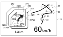
- FIG. 2 is a diagram illustrating a first state of one display example of the display control apparatus according to the first embodiment.
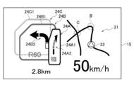
- FIG. 3 is a diagram illustrating a second state of the display example of the display control apparatus according to the first embodiment.
- FIG. 4 is a diagram illustrating a third state of one display example of the display control apparatus according to the first embodiment.
- FIG. 5 is a flowchart showing the operation procedure of the display control apparatus according to the first embodiment.
- FIG. 6 is a diagram illustrating a display example of the display control apparatus according to the second embodiment.
- FIG. 7 is a diagram illustrating a first state of one display example of the display control apparatus according to the third embodiment.
- FIG. 8 is a diagram illustrating a second state of one display example of the display control apparatus according to the third embodiment.
- FIG. 9 is a block diagram showing the configuration of the display control apparatus according to the fourth embodiment.
- FIG. 10 is a diagram illustrating a display example of the display control apparatus according to the fourth embodiment.
- FIG. 11 is a diagram illustrating another display example of the display control apparatus according to the fourth embodiment.
- FIG. 12 is a flowchart illustrating an operation procedure of the display control apparatus according to the fourth embodiment.
- FIG. 13 is a diagram illustrating a display example of the display control apparatus according to the fifth embodiment.
- FIG. 14 is a diagram illustrating a display example of the display control apparatus according to the fifth embodiment.
- FIG. 15 is a diagram for explaining an example of timing at which the display control apparatus according to the fifth embodiment changes the display mode of the speed limit display image.
- FIG. 16 is a diagram for explaining another example of timing at which the display control apparatus according to the sixth embodiment changes the display form of the speed limit display image.
- FIG. 17 is a diagram for explaining another example of timing at which the display control apparatus according to the sixth embodiment changes the display form of the speed limit display image.
- FIG. 18 is a diagram for explaining another example of timing at which the display control apparatus according to the sixth embodiment changes the display form of the speed limit display image.
- the display control device, the display control method, and the display control program in each embodiment are not limited to use for vehicles such as automobiles.
- vehicles include a vehicle-mounted or portable navigation device, a head-up display, an instrument panel, and the like.
- the present invention can be applied to various devices such as portable terminals carried by humans, wearing types, and bicycle applications such as portable terminals and head mounted displays.
- the display control device 1 is configured as a function realized by the control unit 16.
- the display control device 1 cooperates with the GPS reception unit 11, the input unit 12, the vehicle speed sensor 13, the map data storage unit 14, and the display unit 15.
- the display control device 1 may be configured to include at least one of the GPS receiving unit 11, the map data storage unit 14, and the display unit 15.
- the control unit 16 includes at least functions of a current position information acquisition unit 161, a route identification unit 162, a point information acquisition unit 164, and a display control unit 166. Moreover, the control part 16 may be provided with the function of the moving speed acquisition part 163 and the distance calculation part 165 as needed.
- the display control device 1 may have a function provided in a conventionally known navigation device that performs route guidance while displaying a necessary map on a display screen.
- the GPS receiver 11 receives a signal transmitted from a GPS (Global Positioning System) satellite and calculates a current position.
- the GPS reception unit 11 gives the calculated current position information to the current position information acquisition unit 161 of the control unit 16.
- the input unit 12 is input by the user of the moving object when the route specification by the route specifying unit 162 is specified based on the recommended route to the destination or specified by the route scheduled to travel. Accept destination setting and route input.
- the display unit 15 described later has a function of a touch panel display device in which information corresponding to a position touched by a finger of the operator such as a user of the moving body touching the screen is input.
- the display unit 15 may also serve as the input unit 12.
- the vehicle speed sensor 13 is mounted on the host vehicle as a moving body, generates a vehicle speed signal according to the vehicle speed of the host vehicle, and gives the generated vehicle speed signal to the moving speed acquisition unit 163 of the control unit 16.
- the movement speed acquisition unit 163 acquires the vehicle speed information of the host vehicle from the vehicle speed sensor via CAN (Controller Area Network).
- CAN Controller Area Network
- the moving speed acquisition unit 163 The moving speed may be calculated based on the acquired temporal transition of the current position.
- the map data storage unit 14 stores at least a road on which a vehicle can travel and a map around the road, data such as buildings and natural objects such as mountains existing around the road, and point information.
- data such as buildings and natural objects such as mountains existing around the road
- point information When the moving body is other than a vehicle such as a person, data such as roads and passages on which the person can move and facilities around them are stored.
- the map data storage unit 14 may be a storage device mounted on the display control device 1 or a storage device connected to the display control device 1, and is an external storage device that can be used using a communication line. May be.
- the point information is present at a predetermined point on the specified route (or related to the specified route), and is guided to the user of the own vehicle that is a moving body, for example, an occupant or a driver. Indicates the status of a specific point.
- the point information is displayed on the display unit 15 as a point information image on the display unit 15.
- the specific point displayed as the point information is, for example, on a route such as an intersection or a corner (curve) indicating the state of the route on which the host vehicle travels when the moving body is a vehicle.
- a route such as an intersection or a corner (curve) indicating the state of the route on which the host vehicle travels when the moving body is a vehicle.
- the specific point displayed as the point information is a building or a feature such as a mountain or a river that exists around the route and serves as a landmark.
- the point information displayed on the display unit 15 is a shape, a character, or the like that visually explains a specific point. For example, the shape of an intersection or corner, the traveling direction, the radius of curvature, the distance between the current position and the specific point.
- a plurality of point information images in which at least one point information is represented by one image are displayed on the display unit 15 under the control of the display control unit 166 of the control unit 16 to be described later.
- the display unit 15 displays at least one of the distance from the host vehicle to the point where the point information exists, the speed of the host vehicle, and a map around the route traveled by the host vehicle including the route traveled by the host vehicle. You may be made to do.
- the display unit 15 is configured by a device that can display an image such as a liquid crystal display device, and is installed at a position where the driver of the host vehicle can visually recognize, for example, a position where an instrument panel is disposed. Or the display part 15 is comprised with the head-up display which projects an image on a combiner and a windshield, and shows information to a driver
- the display unit 15 controls the display form of the image under the control of the display control unit 166.
- the control unit 16 functions as a control center that controls the operation of the display control device 1, and manages and controls the operation of the display control device 1.
- the control unit 16 can be configured by a microcomputer including resources such as a CPU and a storage device that control various operation processes based on a control program, for example.
- the control unit 16 is stored in a storage unit (not shown) and executed by the display control device 1 based on a control program that controls the overall operation of the display control device 1 including the display operation of the point information image. Control the behavior.
- the display control methods according to the first to third embodiments can be realized by causing the control unit 16 to execute a display control program included in the control program.
- the display control program may be provided by being recorded on a non-temporary recording medium, or distributed via a communication line such as the Internet.
- the display control program recorded on the recording medium and the display control program distributed via the communication line may be stored in the display control device 1 to execute the display control method.
- the current position information acquisition unit 161 acquires the current position information of the host vehicle calculated by the GPS reception unit 11.
- the current position information acquisition unit 161 gives the acquired current position information of the host vehicle to the route specifying unit 162, the distance calculation unit 165, and the display control unit 166.
- the route specifying unit 162 specifies the route on which the host vehicle is traveling, for example, using any one of the following specifying methods 1 to 3 while referring to the map data storage unit 14 as necessary.
- the route specifying unit 162 searches for a recommended route from the current position of the host vehicle to the destination input via the input unit 12, and specifies the specified method 1 for specifying the searched recommended route as a route traveled by the host vehicle. Use to identify.
- the route specifying unit 162 specifies the route that follows the road without turning right or left with respect to the route in the traveling direction of the host vehicle by using the specifying method 2 that specifies the route that the host vehicle travels.
- the specifying method 2 is suitable when the route on which the vehicle is traveling has few branches such as intersections, for example, when traveling on a highway or a suburb.
- the route specifying unit 162 calls a route previously set by the user and stored in a storage device (not shown), or an existing route saved in the storage device in advance, such as a circuit course, for example. It specifies using the specifying method 3 which specifies as a path
- the route specifying unit 162 gives the specified route data to the point information acquiring unit 164 and the display control unit 166.
- the moving speed acquisition unit 163 acquires the vehicle speed of the host vehicle from the vehicle speed sensor 13 or the like.
- the movement speed acquisition unit 163 provides the display control unit 166 with the movement speed that is the acquired vehicle speed.
- the point information acquisition unit 164 exists on the route specified by the route specifying unit 162, and displays a plurality of point information indicating the state of each of a plurality of specific points that are guided to an occupant of the host vehicle that is a moving body. get.
- the point information acquisition unit 164 refers to the map data storage unit 14 and acquires the position of the point where the point information exists on the route specified by the route specifying unit 162.
- the point information acquisition unit 164 refers to the map data storage unit 14 and acquires, for example, a corner or an intersection as point information if there is a corner or an intersection on the route specified by the route specifying unit 162.
- the point information acquisition unit 164 gives the position of the point where the acquired point information exists on the route to the distance calculation unit 165.
- the point information acquisition unit 164 gives the acquired point information to the display control unit 166.
- the distance calculation unit 165 is based on the current position of the host vehicle given from the current position information acquisition unit 161 and the position of the point where the point information given from the point information acquisition unit 164 is on the route. The distance between the current position and the point where the point information exists is calculated. The distance calculation unit 165 gives the calculated distance to the display control unit 166.
- the display control unit 166 arranges a plurality of point information images corresponding to a plurality of point information in the order in which the vehicle as a moving body passes through a plurality of specific points.
- the display control unit 166 performs control so that two point information images adjacent to each other in the order in which the host vehicle passes through a plurality of specific points are displayed by partially overlapping the display position of the display unit 15 on the screen. .
- the display control unit 166 displays the plurality of point information images on the display unit 15 so that the two adjacent point information images are overlapped from the front to the back in the order in which the host vehicle passes through the plurality of specific points. Control to display.
- the display control unit 166 refers to the map data storage unit 14 and displays the route traveled by the host vehicle specified by the route specifying unit 162 on the display unit 15 including a map around the current position of the host vehicle. Control as follows.
- the display control unit 166 controls the vehicle speed given from the moving speed acquisition unit 163 to be displayed on the display unit 15 with characters or the like.
- the display control unit 166 controls the display unit 15 to display the distance from the current position of the host vehicle given by the current position information acquisition unit 161 to the point where the point information appears next in characters or the like.
- the display control unit 166 does not necessarily need to control the display unit 15 to display the vehicle speed or the distance from the current position of the host vehicle to the point where the point information appears next. Whether or not can be determined as appropriate.
- the vehicle speed sensor 13, the movement speed acquisition unit 163, and the distance calculation unit 165 are displayed on the display control device 1. It may be deleted from the configuration requirement.
- FIG. 2 schematically shows a display example in which the above-described point information image and characters are displayed on the screen of the display unit 15 under the control of the display control unit 166.
- the display control executed by the display control unit 166 will be described with reference to FIG.
- the display control unit 166 controls the display unit 15 to display the route 21 on which the host vehicle specified by the route specifying unit 162 travels and the current position 22 of the host vehicle on the route 21 as shown in FIG. To do.
- the host vehicle travels from the current position 22 along the route 21 shown in FIG. 2 in the direction indicated by the arrow 23, passes through point A on the route 21, and then passes through point B and point C. To do.
- Point A is a corner where the state of the route 21 turns to the right with respect to the traveling direction of the host vehicle.
- Point B is a corner where the state of the route 21 turns to the left with respect to the traveling direction of the host vehicle.
- Point C is an intersection of a crossroad that can go straight, turn left, and turn right with respect to the traveling direction of the host vehicle.
- the point information acquisition unit 164 acquires the point information of the points A, B, and C of the specified route after the route on which the host vehicle travels is specified. That is, the point information acquisition unit 164 acquires that the point A is a corner turning rightward as the point information of the point A.
- the point information acquisition unit 164 acquires, as the point information of the point B, that the point B is a corner turning to the left side, and acquires, as the point information of the point C, that the point C is an intersection of the crossroads.
- the display control unit 166 controls, for example, three point information images 24A, 24B, and 24C to be simultaneously displayed on the screen of the display unit 15 as illustrated in FIG. Note that the display control unit 166 can appropriately determine the number of point information images to be simultaneously displayed on the screen of the display unit 15 without limiting to three.
- Each of the point information images 24A, 24B, and 24C is an image that schematically represents the content of the point information, and is an image that allows the passenger of the host vehicle to visually determine the content of the point information.
- the point information image 24A is an image indicating point information of the point A, and is an image indicating point information indicating that the corner turns to the right with respect to the traveling direction of the host vehicle.
- the point information image 24B is an image showing point information of the point B, and is an image showing point information indicating that the corner turns to the left with respect to the traveling direction of the host vehicle.
- the point information image 24C is an image indicating point information of the point C, and is an image indicating point information that the point C is an intersection of a crossroad with respect to the traveling direction of the host vehicle.
- the display control unit 166 controls the display unit 15 to display the point information image of the point information of the passing point on the display unit 15 in the order of passing the point where the point information exists when traveling on the set route.
- the host vehicle travels on a route 21 as shown in FIG. 2, the host vehicle is scheduled to pass through point A, point B, and point C in this order.
- the display control unit 166 displays the point information image 24A corresponding to the point A, the point information image 24B corresponding to the point B, and the point information image 24C corresponding to the point C in this order.
- the display control unit 166 performs control so that the point information image 24B and the point information image 24C are adjacent to each other and are displayed with their display positions shifted from the front to the back of the screen of the display unit 15.
- the direction in which the display position is shifted is the upper left direction of the screen of the display unit 15, but is not limited to the upper left direction of the screen of the display unit 15 and can be determined as appropriate.
- the display control unit 166 performs control so that the point information images 24A, 24B, and 24C are shifted and displayed in a state where the point information images 24A, 24B, and 24C are partially overlapped. That is, the display control unit 166 performs control so that a part of the image area of the point information image 24A and the point information image 24B is superimposed and displayed. The display control unit 166 controls to superimpose and display a part of the image area of the point information image 24B and the point information image 24C.
- the display control unit 166 can appropriately determine an area to superimpose a part of the image area of each point information image 24A, 24B, 24C and a place to superimpose.
- the point information image 24A is an image in which an arrow 24A2 schematically representing a corner turning rightward is displayed inside the display frame 24A1.
- the display control unit 166 performs control so that a part of the image area of the point information image 24A is superimposed on a part of the image area of the point information image 24B.
- the display control unit 166 controls the point information image 24A to be displayed in a translucent display form that transmits light semi-transparently. Thus, the viewer can determine the display content of the point information image 24B via the point information image 24A displayed in front of the point information image 24B.
- the display control unit 166 displays the point information image 24B in a translucent display form in addition to the point information image 24A so that the display content of the point information image 24C can be determined via the point information images 24A and 24B. You may make it display.
- the display control unit 166 controls to display the image indicating the arrow 24A2 of the point information image 24A in three parts, that is, a base part 24A21, an intermediate part 24A22, and a tip part 24A23.
- the base portion 24A21 represents a position before the corner
- the intermediate portion 24A22 represents a corner
- the distal end portion 24A23 represents a position passing through the corner.
- the display control unit 166 changes the display form of the image of each of the three parts (base 24A21, intermediate part 24A22, tip part 2A23) according to the current position 22 of the host vehicle.
- the display control unit 166 sets the display color of the image of each part to a display color different from that of the other parts when the host vehicle is traveling at the position represented by each part.
- the display form to be changed is arbitrary, and the display color inside the contour line may be changed to a display color different from the display color of each other part, leaving only the contour line.
- the display control unit 166 displays the base portion 24A21 in a display form different from the intermediate portion 24A22 and the distal end portion 2A23 as shown in FIG. Change to
- the display control unit 166 changes the base 24A21 to the original display form as shown in FIG.
- the display control unit 166 changes the intermediate part 24A22 to a display form different from the base part 24A21 and the distal end part 2A23, as shown in FIG.
- the display control unit 166 may display the curvature radius of the corner on the point information image indicating the corner point information.
- the display control unit 166 displays the radius of curvature of the corner of the point A as, for example, “R100” on the point information image 24A.
- the point information image 24B is an image in which an arrow 24B2 schematically representing a corner turning leftward is displayed inside the display frame 24B1.
- the display control unit 166 displays the image indicating the arrow 24B2 in three parts, that is, a base part 24B21, an intermediate part 24B22, and a tip part 24B23.
- the display control unit 166 changes the display form of the image indicating the arrow 24B2 in the same manner as the image indicating the arrow 24A2 of the point information image 24A described above according to the current position of the host vehicle.
- the display control unit 166 performs control so that a part of the image area of the point information image 24B is superimposed on a part of the image area of the point information image 24A. At this time, the viewer can determine the image indicating the arrow 24B2 via the point information image 24A displayed in a semitransparent display form in front of the point information image 24B.
- the point information image 24C is an image showing point information of the point C, and is an image showing point information that the point C is a crossroad intersection with respect to the traveling direction of the host vehicle.
- the point information image 24C shows a display example in which only a part of the display frame 24C1 is displayed. However, when the entire point information image 24C is displayed, as shown in FIG. Is displayed.
- the point information image 24 ⁇ / b> C is an image in which a cross 24 ⁇ / b> C ⁇ b> 2 schematically representing an intersection of a crossroad is displayed inside the display frame 24 ⁇ / b> C ⁇ b> 1.
- the display control unit 166 controls the image showing the cross 24C2 to display the specified route, for example, as a solid line, and to display other routes other than the specified route as a broken line.
- the display control unit 166 displays, on the image showing the cross 24C2, a route before the intersection and a route that turns right at the intersection with solid lines, and a route that goes straight through the intersection and a route that turns left at the intersection with broken lines. Control as follows.
- the display control unit 166 controls to display the image of the route displayed with a solid line in the image showing the cross 24C2 in two parts, that is, the base 24C21 and the right turn part 24C22.
- the base 24C21 is an image showing a route before the intersection
- the right turn 24C22 is an image showing a route turning right at the intersection.
- the display control unit 166 displays the image of the route displayed as a solid line in the image indicating the cross 24C2 in the same manner as the image indicating the arrow 24A2 of the point information image 24A described above according to the current position of the host vehicle. Change. In addition, the display form may not be changed according to the current position of the host vehicle other than the point information image that is closest to the front.
- the display control unit 166 displays the current vehicle speed of the host vehicle in characters under the image showing the identified route 21. In the display example of FIG. 2, for example, 60 km / h is displayed.
- the display control unit 166 displays characters indicating the distance from the current position of the host vehicle to the point A of the point information corresponding to the point information image 24A below the point information image 24A. In the display example of FIG. 2, it is displayed as 1.3 km.
- the display control unit 166 controls the display of the display frames 24A1, 24B1, and 24C1 of the point information images 24A, 24B, and 24C so as to be lightened in the order of the display frames 24A1, 24B1, and 24C1. .
- the current position information acquisition unit 161 acquires the current position of the host vehicle based on the signal from the GPS satellite received by the GPS reception unit 11 in step S11.
- the moving speed acquisition unit 163 acquires the vehicle speed of the host vehicle based on the vehicle speed signal provided from the vehicle speed sensor 13 in step S11.
- step S12 the route specifying unit 162 refers to the map data storage unit 14 as necessary, and sets the route on which the host vehicle travels using any one of the setting methods 1 to 3 described above. Identify. In the identification methods 1 and 3, the route is identified in advance before the start of step S11.
- step S13 the point information acquisition unit 164 refers to the map data storage unit 14, and obtains the above-described plurality of point information existing in the route specified by the route specifying unit 162 at the point where the point information appears on the route. Get including position.
- step S14 the distance calculation unit 165 determines the current position of the host vehicle based on the current position of the host vehicle provided from the current position information acquisition unit 161 and the position of the point information provided from the point information acquisition unit 164. The distance from the point where the point information exists is calculated.
- step S15 the display control unit 166 refers to the map data storage unit 14, includes the route traveled by the host vehicle set by the route specifying unit 162, including a map around the route traveled by the host vehicle, and the like. Control to display on the display unit 15.
- step S ⁇ b> 15 the display control unit 166 controls the display unit 15 to display a plurality of point information images representing the point information existing on the identified route as images.
- the display control device 1 according to the first embodiment can obtain the following effects by including the technical features described above.
- the display control apparatus 1 displays a plurality of point information images by superimposing a part of the image area of the point information image, so that the viewer can grasp the display contents represented by the point information image.
- a plurality of point information images can be displayed in an easy display form.
- FIG. 6 schematically shows a display example in which the point information images 24A, 24B, and 24C are displayed on the screen of the display unit 15 under the control of the display control unit 166.
- the point information images 24A, 24B, 24C displayed on the screen of the display unit 15 of the second embodiment are the point information images 24A, 24B, 24C displayed on the screen of the display unit 15 of the first embodiment.
- the display form is different compared to
- the display control unit 166 of the second embodiment can determine the display content of the point information image 24B (second point information image) displayed in the back adjacent to the point information image 24A (first point information image).
- the point information images 24A and 24B are controlled so as to be superimposed and displayed.
- the display control unit 166 of the second embodiment does not control to display the point information image 24A in a semi-transparent display form.
- the display control unit 166 of the second embodiment displays the point information images 24A, 24B, and 24C so that the viewer can determine the display contents of the point information displayed in the point information images 24A, 24B, and 24C. Controls the display so as to be superimposed and shifted.
- the display control unit 166 of the second embodiment performs an amount of shifting the point information images 24B and 24C with respect to the point information image 24A in the first implementation. More than the form. Thereby, the display control unit 166 reduces the area where the point information image 24A and the point information image 24B overlap and the area where the point information image 24B and the point information image 24C overlap as compared with the first embodiment. .
- the entire image indicating the arrow 24B2 of the point information image 24B cannot be visually recognized because a part of the image indicating the arrow 24B2 is hidden behind the point information image 24A displayed in front.
- a part of the image indicating the arrow 24B2 of the point information image 24B can be visually recognized by the viewer. . Thereby, the viewer can grasp the content of the point information that is the corner of the left turn that is the display content of the point information image 24B.
- the entire image showing the cross 24C2 of the point information image 24C cannot be visually recognized because a part of the image showing the cross 24C2 is hidden behind the point information image 24B displayed in front.
- a part of the image showing the cross 24C2 of the point information image 24C can be visually recognized by the viewer. . Thereby, the viewer can grasp the content of the point information that is the intersection of the cross road, which is the display content of the point information image 24C.
- the display control apparatus 1 according to the second embodiment can obtain the following effects by including the technical features described above.
- the display control apparatus 1 includes a plurality of display forms that can easily grasp the display content represented by the point information image 24B without displaying the point information image 24A displayed at the foremost side in a translucent manner. A point information image can be displayed.
- a feature of the display operation executed by the display control device 1 according to the third embodiment is that the point information image is deleted from the screen of the display unit 15 after changing the display form of the point information image that is no longer necessary to be displayed. Is a point.
- the display control unit 166 of the third embodiment displays the point information image 24A. Change the display form. After changing the display form of the point information image 24A, the display control unit 166 of the third embodiment deletes the point information image 24A and displays the point information image 24B (second point information image) on the screen of the display unit 15. Display in front.
- the display control unit 166 displays the point information image that has been displayed up to the forefront of the screen of the display unit 15. Change the display form and delete the point information image from the screen.
- the display control unit 166 turns the point information image 24A as if the page of the book or the superimposed card is turned to the right side as shown in FIG. The display form is changed so that the page appears, and then the page is erased.
- the display control unit 166 changes the point information image 24B displayed in the back of the point information image 24A from the display form that has been displayed in the actual display until then, as shown in FIG. Change to, and control to display in front of the screen.
- the display control unit 166 superimposes a part of the point information image 24D displayed next to the point information image 24C on a part of the image area of the point information image 24C, Control is performed so that the point information image 24C is displayed in the back.
- the display control unit 166 gradually reduces the display density of the point information image that has been displayed at the forefront until then.
- the display form of the point information image is changed.
- the display control unit 166 erases the point information image from the screen by changing the display form of the point information image in this way.
- the display control unit 166 gradually reduces the display size of the point information image that has been displayed at the forefront until then.
- the display form of the point information image is changed.
- the display control unit 166 erases the point information image from the screen by changing the display form of the point information image in this way.
- the display control apparatus 1 according to the third embodiment can obtain the following effects in addition to the effects obtained in the first and second embodiments by including the technical features described above. .
- the display control device 1 of the third embodiment changes the display form of the point information image that is no longer required to be deleted from the screen of the display unit 15.
- the display control apparatus 1 of 3rd Embodiment visually recognizes that the own vehicle passed the point corresponding to a point information image compared with the method of erasing the whole simultaneously, without changing the display form of a point information image.
- the person can be made to recognize more reliably with less discomfort.
- the display control device 2 With reference to FIG. 9, the structure of the display control apparatus which concerns on 4th Embodiment is demonstrated.
- the display control device 2 will be described as a display control device for a vehicle used in a vehicle such as an automobile, which is a moving body that moves on a traveling path.
- the point information in the fourth to sixth embodiments is a speed limit associated with the specified route. 9, parts that are the same as those in FIG. 1 are given the same reference numerals, and explanation thereof is omitted.
- the display control device 2 is configured as a function realized by the control unit 17, and, as an example, cooperates with the GPS receiving unit 11, the input unit 12, the map data storage unit 14, and the display unit 15. Further, the display control device 2 may be configured to include at least one of the GPS receiving unit 11, the map data storage unit 14, and the display unit 15.
- the display control device 2 may have a function provided in a known navigation device that performs route guidance while displaying a necessary map on a display screen.
- the control unit 17 includes functions of a current position information acquisition unit 161, a route identification unit 162, a speed limit acquisition unit 171 and a display control unit 172.
- the map data storage unit 14 stores at least map data of a travel path where the vehicle can travel and the vicinity of the travel path.
- the map data storage unit 14 stores at least information related to the travel path on which the vehicle can travel and the periphery of the travel path.
- the map data storage unit 14 stores at least the speed limit of the travel path as information regarding the travel path.
- the display form of the display unit 15 is controlled by the display control unit 172.
- the control unit 17 functions as a control center that controls the operation of the display control device 2, and controls and controls the operation of the display control device 2 in an integrated manner.
- the control unit 17 can be configured by a computer having resources such as a CPU and a storage device that control various operation processes based on a control program.
- the control unit 17 controls an operation executed by the display control device 2 based on a control program stored in a storage device (not shown) and controlling the overall operation of the display control device 2.
- the display control method according to the fourth embodiment, the fifth embodiment, and the sixth embodiment can be realized by executing the display control program included in the control program by the control unit 17.
- the display control program may be provided by being recorded on a non-temporary recording medium, or distributed via a communication line such as the Internet.
- the display control program recorded on the recording medium and the display control program distributed via the communication line may be stored in the display control device 2 to execute the display control method.
- the current position information acquisition unit 161 acquires the current position information of the host vehicle calculated by the GPS reception unit 11.
- the current position information acquisition unit 161 gives the acquired current position information of the host vehicle to the route specification unit 162, the speed limit acquisition unit 171 and the display control unit 172.
- the route specifying unit 162 determines whether information necessary for specifying a route is given from the input unit 12. When the information necessary for specifying the route is given from the input unit 12, the route specifying unit 162 refers to the map data stored in the map data storage unit 14 as necessary to determine the route on which the host vehicle travels. Identify. The route specifying unit 162 searches for a recommended route from the current position of the host vehicle to the destination input via the input unit 12, for example, and specifies the searched recommended route as a route on which the host vehicle travels. The route specifying unit 162 provides the specified route data to the speed limit obtaining unit 171 and the display control unit 172.
- the speed limit acquisition unit 171 travels when the host vehicle travels by any of the following methods based on the current position of the host vehicle and the route specified by the route specifying unit 162 based on the specified route. Get the road speed limit.
- the speed limit acquisition unit 171 inputs and acquires the speed limit of the travel path stored in the map data storage unit 14 corresponding to the travel path of the host vehicle.
- the speed limit obtaining unit 171 When the speed limit obtaining unit 171 has a communication function for communicating with the outside, the speed limit obtaining unit 171 communicates with an external providing server that provides road information, so that the speed limit of the travel path is set from the external providing server. To get.
- the speed limit acquisition unit 171 acquires the speed limit using the function included in the navigation device.
- the speed limit acquisition unit 171 is as follows. Get the speed limit.
- the speed limit acquisition unit 171 acquires the speed limit of the travel path as external data from the external provision server through communication with the external provision server.
- the speed limit acquisition unit 171 acquires the speed limit based on the captured image obtained by the in-vehicle camera.
- the speed limit acquisition unit 171 inputs speed limit recognition information obtained by recognizing the speed limit displayed on the road sign or road sign based on the captured image of the road sign or road sign taken by the in-vehicle camera.
- the speed limit acquisition unit 171 acquires the speed limit based on the speed limit recognition information.
- the speed limit acquisition unit 171 gives the acquired speed limit to the display control unit 172.
- the display control unit 172 controls the display form of the speed limit display image.
- the speed limit display image is any one of the first to fourth speed limit display images
- the speed limit display image is any one of the first to fourth speed limit display images.
- the image is not specified, it is simply referred to as a speed limit display image.
- the speed limit display image is included in the point information image.
- the first speed limit display image is an image indicating that the speed limit of the first travel path (first travel path) on which the host vehicle currently travels is the first speed limit.
- the second speed limit display image shows a second speed limit where the speed limit of the second travel path (second travel path) in which the host vehicle travels following the first travel path is different from the first speed limit. It is an image which shows that it is.
- the third speed limit display image is an image indicating that the speed limit of the third travel path in which the host vehicle travels following the second travel path is a third speed limit different from the second speed limit. is there.
- the fourth speed limit display image is an image indicating that the speed limit of the fourth travel path in which the host vehicle travels following the third travel path is a fourth speed limit different from the third speed limit. is there.
- the display control unit 172 performs control so that at least the first speed limit display image and the second speed limit display image are displayed by partially superimposing the display positions on the screen.
- the display control unit 172 displays the first speed limit display image in the foreground and the first speed limit display image is adjacent to the first speed limit display image so that the second speed limit display image is overlapped in the back.
- the speed limit display image and the second speed limit display image are arranged.
- the display control unit 172 displays the first speed limit display image and the second speed limit display image so that the first speed limit display image and the second speed limit display image are arranged as described above.
- the display unit 15 is controlled to display.
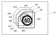
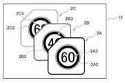
- FIG. 10 and 11 show display examples in which the first to third speed limit display images are arranged and displayed on the screen of the display unit 15 under the control of the display control unit 172.
- FIG. With reference to FIG.10 and FIG.11, the control of the display form of the speed limit display image which the display control part 172 performs is demonstrated.
- FIG. 10 shows a display example in which a third speed limit display image 2C is displayed in addition to the first speed limit display image 2A and the second speed limit display image 2B.
- FIG. 11 shows a display example in which a fourth speed limit display image 2D is displayed in addition to the second speed limit display image 2B and the third speed limit display image 2C.
- the display control unit 172 may be controlled to display at least two speed limit display images. In FIG. 10, the display control unit 172 may control to display at least the first speed limit display image 2A and the second speed limit display image 2B, and may not display the third speed limit display image 2C. Good. In FIG. 11, the display control unit 172 may control to display at least the second speed limit display image 2B and the third speed limit display image 2C, and may not display the fourth speed limit display image 2D. Good.
- the display control unit 172 can appropriately determine the number of speed limit display images to be simultaneously displayed on the screen of the display unit 15 without being limited to two or three.
- the first speed limit display image 2A, the second speed limit display image 2B, the third speed limit display image 2C, and the fourth speed limit display image 2D are images that schematically represent the speed limit, It is an image in which the passenger of the host vehicle can recognize the speed limit visually.
- the first speed limit display image 2A is an image in which a sign image 2A2 schematically representing a road sign indicating a speed limit of 60 km / h is displayed inside the display frame 2A1.
- a numerical value 2A3 of the sign image 2A2 indicates a speed limit, and a numerical value 60 indicates that the speed limit is 60 km / h.
- the colors of the display frame 2A1, the sign image 2A2, and the background 2A4 between the display frame 2A1 and the sign image 2A2 can be set independently and arbitrarily.
- the second speed limit display image 2B is an image in which a sign image 2B2 schematically representing a road sign indicating a speed limit of 40 km / h is displayed inside the display frame 2B1.
- a numerical value 2B3 of the sign image 2B2 indicates a speed limit, and a numerical value 40 indicates that the speed limit is 40 km / h.
- the colors of the display frame 2B1, the sign image 2B2, and the background 2B4 between the display frame 2B1 and the sign image 2B2 can be set independently and arbitrarily in any color.
- the third speed limit display image 2C is an image in which a sign image 2C2 schematically representing a road sign indicating a speed limit of 60 km / h is displayed inside the display frame 2C1.
- a numerical value 2C3 of the sign image 2C2 indicates a speed limit, and a numerical value 60 indicates that the speed limit is 60 km / h.
- the colors of the display frame 2C1, the sign image 2C2, and the background 2C4 between the display frame 2C1 and the sign image 2C2 can be set independently and arbitrarily in any color.
- the fourth speed limit display image 2D cannot be recognized as a whole in FIG. 11, but is an image in which a sign image (not shown) schematically representing a road sign indicating the speed limit is displayed inside the display frame 2D1. is there.
- the numerical value (not shown) of the sign image indicates the speed limit.
- the colors of the display frame 2D1, the sign image, and the background 2D4 between the display frame and the sign image can be set independently and arbitrarily.
- the display control unit 172 performs control so that the first speed limit display image 2 ⁇ / b> A is displayed on the front side when the host vehicle travels on the first travel path.
- the display control unit 172 arranges the first speed limit display image 2A and the second speed limit display image 2B in a state in which the display positions are partially overlapped with each other shifted in display position.
- the display control unit 172 includes the first speed limit display image 2 ⁇ / b> A and the second speed limit display image 2 ⁇ / b> A so that the second speed limit display image 2 ⁇ / b> B overlaps with the first speed limit display image 2 ⁇ / b> A in the back.
- the speed limit display image 2B is controlled to be displayed.
- the display control unit 172 displays the second speed limit display behind the background 2A4 other than the sign image 2A2 of the first speed limit display image 2A and the image indicating the numerical value 2A3, for example. Control is performed so that the image 2B is displayed in a semi-transparent display form. Accordingly, the second speed limit indicated by the second speed limit display image 2B can be determined via the first speed limit display image 2A displayed in front of the second speed limit display image 2B.
- the display control unit 172 performs control so that the entire first speed limit display image 2A displayed in the foreground is displayed in a semi-transparent display form with the second speed limit display image 2B behind it. May be. Even in this case, the second speed limit indicated by the second speed limit display image 2B can be determined via the first speed limit display image 2A displayed in front of the second speed limit display image 2B. .
- the viewer recognizes the second speed limit indicated by the second speed limit display image 2B via the first speed limit display image 2A displayed before the second speed limit display image 2B. be able to.
- the display control unit 172 arranges the second speed limit display image 2B and the third speed limit display image 2C in a state in which the display positions are partially overlapped with each other.
- the display control unit 172 includes the second speed limit display image 2B and the third speed limit image 2B so that the third speed limit display image 2C is adjacent to the second speed limit display image 2B and is overlapped in the back. To display the speed limit display image 2C.
- the display control unit 172 performs control so that the second speed limit display image 2 ⁇ / b> B is displayed on the foremost side when the host vehicle travels on the second travel path.
- the display control unit 172 arranges the second speed limit display image 2B and the third speed limit display image 2C in a state in which the display positions are partially overlapped with the display positions shifted.
- the display control unit 172 includes the second speed limit display image 2B and the third speed limit image 2B so that the third speed limit display image 2C is adjacent to the second speed limit display image 2B and is overlapped in the back. To display the speed limit display image 2C.
- the display control unit 172 displays the second speed limit display behind the background 2B4 other than the sign image 2B2 of the second speed limit display image 2B and the image indicating the numerical value 2B3. Control is performed so that the image 2B is displayed in a semi-transparent display form. Accordingly, the third speed limit indicated by the third speed limit display image 2C can be determined via the second speed limit display image 2B displayed in front of the third speed limit display image 2C.
- the display control unit 172 performs control so that the entire second speed limit display image 2B displayed in the foreground is displayed in a semi-transparent display form with the third speed limit display image 2C behind it. May be. Even in this case, the third speed limit indicated by the third speed limit display image 2C can be determined via the second speed limit display image 2B displayed in front of the third speed limit display image 2C. .
- the viewer recognizes the third speed limit indicated by the third speed limit display image 2C via the second speed limit display image 2B displayed in front of the third speed limit display image 2C. be able to.
- the display control unit 172 arranges the third speed limit display image 2C and the fourth speed limit display image 2D in a state in which the display positions are partially overlapped with each other shifted in display position.
- the display control unit 172 includes the third speed limit display image 2C and the fourth speed limit image so that the fourth speed limit display image 2D is overlapped in the back adjacent to the third speed limit display image 2C.
- the speed limit display image 2D is controlled to be displayed.
- the display control unit 172 shifts the display position of the speed limit display image to the upper left direction of the screen of the display unit 15. Not limited to the obliquely upward direction, it can be determined as appropriate.
- the display control unit 172 can appropriately determine the area to superimpose a part of the image area of two adjacent speed limit display images and the location to superimpose.
- the display control unit 172 displays the darkness of the image in the display frame of the speed limit display image so that the image becomes lighter from the front toward the back.
- the display control unit 172 displays the image densities of the display frames 2A1 to 2C1 of the first to third speed limit display images 2A to 2C in the display frames 2A1, 2B1, and 2C1. It is displayed so as to become thinner in order.
- the display control unit 172 displays the image densities of the display frames 2B1 to 2D1 of the second to fourth speed limit display images 2B to 2D in the display frames 2B1, 2C1, and 2D1. It is displayed so as to become thinner in order.
- the current position information acquisition unit 161 acquires the current position of the host vehicle based on the signal from the GPS satellite received by the GPS reception unit 11 in step S41.
- step S42 the route specifying unit 162 determines whether information necessary for specifying the route is given from the input unit 12, and determines whether to specify the route. If the route specifying unit 162 determines in step S42 that information necessary for specifying the route is provided and specifies the route (YES), the process proceeds to step S43.
- the route specifying unit 162 advances the process to step S44.
- the route specifying unit 162 specifies the route on which the host vehicle travels.
- the speed limit acquisition unit 171 determines at least the first travel path and the second travel on the route on which the host vehicle travels based on the current position of the host vehicle. Get the road speed limit.
- the speed limit acquisition unit 171 at least the first travel path and the first travel on which the host vehicle currently travels based on the current position of the host vehicle.
- the speed limit of the second travel path on the road extension is obtained.
- step S45 the display control unit 172 performs control so that the first speed limit display image 2A is displayed on the front side when the host vehicle travels on the first travel path.
- step S45 the display control unit 172 arranges at least the first speed limit display image 2A and the second speed limit display image 2B in a state in which the display positions are partially overlapped with each other.
- step S45 the display control unit 172 displays the first speed limit so that the second speed limit display image 2B overlaps at least in the back adjacent to the first speed limit display image 2A. Control is performed to display the display image 2A and the second speed limit display image 2B. At this time, the display control unit 172 controls to display the first speed limit display image 2A in a semi-transmissive display form.
- the display control device 2 according to the fourth embodiment controls to display a plurality of speed limit display images arranged in a superimposed manner by superimposing a part of the image area of the speed limit display image.
- the display control device 2 according to the fourth embodiment can display a plurality of speed limit display images in a display form in which the viewer can easily recognize the speed limit indicated by the speed limit display image.
- the display control device 2 according to the fourth embodiment reduces the display area where the plurality of speed limit display images are displayed, as compared with the case where the plurality of speed limit display images are arranged and displayed without being superimposed. Can do.
- the first speed limit display image 2 ⁇ / b> A, the second speed limit display image 2 ⁇ / b> B, and the third speed limit display image 2 ⁇ / b> C are displayed on the screen of the display unit 15 under the control of the display control unit 172.
- a display example is schematically shown.
- the first speed limit display image 2A, the second speed limit display image 2B, and the third speed limit display image 2C displayed on the screen of the display unit 15 of the fifth embodiment are the same as those in the fourth embodiment.
- the display form is different.
- the display control unit 172 of the fifth embodiment controls to display the first speed limit display image 2A, the second speed limit display image 2B, and the third speed limit display image 2C as described below. To do.
- the display control unit 172 performs control so that the speed limit display image displayed at the forefront is not displayed in a semi-transparent state but is displayed in a non-translucent state. In the display example shown in FIG. 13, control is performed so that the first speed limit display image 2 ⁇ / b> A is not displayed semi-transparently but displayed in a non-translucent state.
- the display control unit 172 determines the first speed limit so that the second speed limit indicated by the second speed limit display image 2B displayed in the back adjacent to the first speed limit display image 2A can be determined. Control is performed so that the speed display image 2A and the second speed limit display image 2B are superimposed and displayed.
- the display control unit 172 shifts and displays the first speed limit display image 2A and the second speed limit display image 2B in a superimposed manner, the display control unit 172 increases the amount by which both images are shifted compared to the fourth embodiment.
- the display control unit 172 determines the shift amount so that the viewer can recognize the numerical value 2B3 of 40 indicating the second speed limit of the sign image 2B2 of the second speed limit display image 2B.
- the display control unit 172 displays the second speed limit so that the second speed limit indicated by the third speed limit display image 2C displayed in the back adjacent to the second speed limit display image 2B can be determined. Control is performed so that the speed display image 2B and the third speed limit display image 2C are superimposed and displayed.
- the display control unit 172 shifts and displays the second speed limit display image 2B and the third speed limit display image 2C in a superimposed manner, the display control unit 172 increases the amount by which both images are shifted compared to the fourth embodiment.
- the display control unit 172 determines the amount of shift so that the viewer can recognize a numerical value 2C3 of 60 indicating the third speed limit of the sign image 2C2 of the third speed limit display image 2C.
- the display control device 2 of the fifth embodiment does not display the speed limit display image displayed on the foremost side in a semi-transparent manner, but the limit speed display image arranged in the back of the first speed limit display image indicates A plurality of speed limit display images can be displayed in a display form in which the speed can be recognized.
- the display operation performed by the display control device 2 according to the sixth embodiment is characterized in that the speed limit display image is changed from the screen of the display unit 15 after the display mode of the speed limit display image that does not require display is changed. It is a point to erase.
- the map data storage unit 14 stores the position of the point at which the speed limit is switched (the speed limit switching point).
- the speed limit acquisition unit 171 acquires the speed limit
- the speed limit acquisition unit 171 acquires the position of the speed limit switching point together with the speed limit by the above-described method of acquiring the speed limit.
- the speed limit acquisition unit 171 gives the position of the acquired speed limit switching point to the display control unit 172.
- the display control unit 172 switches from the display form of the speed limit display image shown in FIG. 10 to the display form of the speed limit display image shown in FIG. 11, as described below, the display form of the speed limit display image To control.
- the display control unit 172 starts the operation of changing the display form of the first speed limit display image 2A when the host vehicle passes a speed limit switching point where the speed limit is switched from 60 km / h to 40 km / h. For example, as shown in FIG. 14, the display control unit 172 changes the display form of the first speed limit display image 2A so that the next page or card appears as if the page of the book or the superimposed card is turned to the right side.
- the display control unit 172 determines whether or not the host vehicle has reached the speed limit switching point based on the current position of the host vehicle. When the host vehicle reaches the speed limit switching point, the display control unit 172 deletes the first speed limit display image 2A from the screen because the display of the first speed limit display image 2A becomes unnecessary.
- the display control unit 172 changes the second speed limit display image 2B from the display form that has been displayed in the non-translucent state until then to the semi-transparent display form, as shown in FIG. Control to display in the foreground.
- the display control unit 172 displays the third speed limit display image 2C adjacent to the second speed limit display image 2B and shifted from the second speed limit display image 2B. Control. In addition, the display control unit 172 performs control so that the fourth speed limit display image 2D is displayed adjacent to the third speed limit display image 2C while being shifted from the third speed limit display image 2C.
- the display control unit 172 gradually increases the display density of the speed limit display image that has been displayed at the forefront.
- the display form of the speed limit display image is changed so as to be thinner.
- the display control unit 172 erases the speed limit display image from the screen by changing the display form of the speed limit display image in this way.
- the display control unit 172 gradually reduces the display size of the speed limit display image that has been displayed at the forefront until then. Thus, the display form of the speed limit display image is changed.
- the display control unit 172 erases the speed limit display image from the screen by changing the display form of the speed limit display image in this way.
- 15 to 18 show the timing when the display control unit 172 changes the display form of the speed limit display image according to the travel path on which the host vehicle travels.
- the display control unit 172 controls the timing for changing the display form of the speed limit display image as described below.
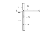
- FIG. 15 is a diagram illustrating an example of the timing in the first case on the traveling path of the host vehicle.
- the first case is when the following first requirement and second requirement, or first requirement and third requirement are satisfied.
- the first requirement is a case where the speed limit acquisition unit 171 acquires the speed limit of the travel path of the host vehicle M regardless of the captured image obtained by the in-vehicle camera.
- the second requirement is that the travel route of the host vehicle M is not set by the route specifying unit 162 and the travel route of the host vehicle M is estimated as an extension of the travel route 71 on which the host vehicle M currently travels. It is.
- the second requirement is that the travel route of the host vehicle M is not set by the function provided in the route specifying unit 162 and the navigation device. is there. That is, the second requirement is a case where the traveling path of the host vehicle M is estimated as an extension of the traveling path 71 on which the host vehicle M is currently traveling.
- the travel path estimated as an extension of the travel path 71 is a travel path 72 that extends above the paper surface following the travel path 71.
- the third requirement is a case where the route specifying unit 162 sets the travel route of the host vehicle M as an extension of the travel route on which the host vehicle M currently travels.
- the third requirement is that the route of the host vehicle M is an extension of the route of travel of the host vehicle M and the route specifying unit 162 Or it is a case where it is set by the function with which the navigation apparatus is provided.
- the travel path set as an extension of the travel path 71 is the travel path 72.
- the traveling path 73 intersects at the connection point between the traveling path 71 and the traveling path 72.
- the travel path 71 has a speed limit of 60 km / h.
- Travel speeds 72 and 73 have a speed limit of 40 km / h.
- the intersection where the traveling path 71 and the traveling path 72 intersect with the traveling path 73 is regarded as a speed limit switching point PA where the speed limit is switched.
- the speed limit switching point is an intersection as an example, but may be a point other than the intersection.
- the change start point 7B where the display control unit 172 starts the operation of changing the display form of the first speed limit display image 2A is set before the speed limit switching point PA.
- the change start point 7B is located before the speed limit switching point PA so that the first speed limit display image 2A is erased from the screen of the display unit 15 when the host vehicle M reaches the speed limit switching point PA. It can be set at any point.
- the display control unit 172 displays, for example, as shown in FIG. 10 when the host vehicle M travels on the traveling path 71. That is, the display control unit 172 performs control so that the first speed limit display image 2A is displayed in a semi-transparent display form in front of the screen of the display unit 15.
- the display control unit 172 performs control so that the second speed limit display image 2B is displayed adjacent to the first speed limit display image 2A and partially overlapped with the first speed limit display image 2A. . Further, the display control unit 172 controls to display the third speed limit display image 2C adjacent to the second speed limit display image 2B and partially overlapping the second speed limit display image 2B in the back. .
- the display control unit 172 determines whether or not the host vehicle M has reached the change start point 7B based on the current position of the host vehicle M. When the host vehicle M reaches the change start point 7B, the display control unit 172 starts an operation of changing the display form of the first speed limit display image 2A. For example, as shown in FIG. 14, the display control unit 172 changes the display form of the first speed limit display image 2A so that the next page or card appears as if the page of the book or the superimposed card is turned to the right side.
- the display control unit 172 determines whether or not the host vehicle M has reached the speed limit switching point PA based on the current position of the host vehicle M. When the host vehicle M reaches the speed limit switching point PA, the display control unit 172 deletes the first speed limit display image 2A from the screen of the display unit 15.
- the display control unit 172 displays, for example, as shown in FIG. That is, the display control unit 172 controls the second speed limit display image 2B to be displayed in the forefront of the screen by changing the display form that has been displayed in the non-translucent state to the semi-transparent display form. To do. Further, the display control unit 172 performs control so that the third speed limit display image 2C is displayed adjacent to the second speed limit display image 2B and partially overlapped with the second speed limit display image 2B in the back. . In addition, the display control unit 172 controls to display the fourth speed limit display image 2D adjacent to the third speed limit display image 2C and partially overlapping the third speed limit display image 2C in the back. .
- FIG. 16 shows an example of the change timing of the display form of the speed limit display image in the second case.
- the second case is when the first requirement and the fourth requirement are satisfied.
- the fourth requirement is a case where the route specifying unit 162 sets the travel route of the host vehicle M as a travel route that is not an extension of the travel route on which the host vehicle M currently travels, for example, a travel route that turns right or left. .
- the fourth requirement is that the travel path is set by a function provided in the route specifying unit 162 or the navigation device.
- the traveling path of the host vehicle M is set to a traveling path 73 that turns right at an intersection where the traveling path 71 and the traveling path 73 intersect, following the traveling path 71 on which the host vehicle M currently travels. .
- the traveling road 71 has a speed limit of 60 km / h.
- the travel path 73 has a speed limit of 40 km / h. Therefore, here, as in the case of FIG. 15, the intersection where the traveling path 71 and the traveling path 73 intersect is regarded as the speed limit switching point PA.
- the change start point 7B where the display control unit 172 starts the operation of changing the display form of the first speed limit display image 2A is the same as in FIG.
- the display control unit 172 controls the display mode of the speed limit display image as in the case of the first case described with reference to FIG.
- the display control unit 172 displays, for example, as shown in FIG.
- the display control unit 172 performs control so that the first speed limit display image 2A is displayed in a semi-transparent display form in front of the screen of the display unit 15.
- the display control unit 172 performs control so that the second speed limit display image 2B is displayed adjacent to the first speed limit display image 2A and partially overlapped with the first speed limit display image 2A. .
- the display control unit 172 performs control so that the third speed limit display image 2C is displayed adjacent to the second speed limit display image 2B and partially overlapped with the second speed limit display image 2B in the back.
- the display control unit 172 determines whether or not the host vehicle M has reached the change start point 7B based on the current position of the host vehicle M. When the host vehicle M reaches the change start point 7B, the display control unit 172 starts an operation of changing the display form of the first speed limit display image 2A. For example, as shown in FIG. 14, the display control unit 172 changes the display form of the first speed limit display image 2A so that the next page or card appears as if the page of the book or the superimposed card is turned to the right side.
- the display control unit 172 determines whether or not the host vehicle M has reached the speed limit switching point PA based on the current position of the host vehicle M. When the host vehicle M reaches the speed limit switching point PA, the display control unit 172 deletes the first speed limit display image 2A from the screen of the display unit 15.
- the display control unit 172 displays, for example, as shown in FIG. That is, the display control unit 172 controls the second speed limit display image 2B to be displayed in the forefront of the screen by changing the display form that has been displayed in the non-translucent state to the semi-transparent display form. To do. Further, the display control unit 172 performs control so that the third speed limit display image 2C is displayed adjacent to the second speed limit display image 2B and partially overlapped with the second speed limit display image 2B in the back. . In addition, the display control unit 172 controls to display the fourth speed limit display image 2D adjacent to the third speed limit display image 2C and partially overlapping the third speed limit display image 2C in the back. .
- FIG. 17 shows an example of the change timing of the display form of the speed limit display image in the third case.
- the traveling path of the host vehicle M and the traveling environment of the speed limit are the same as those in FIG.
- the third case is when the second requirement and the following fifth requirement, or the third requirement and the fifth requirement are satisfied.
- the fifth requirement is that the speed limit acquisition unit 171 restricts the travel path of the host vehicle M based on a road sign or a captured image of a road sign captured by an in-vehicle camera (not shown) mounted on the host vehicle M. This is the case to get the speed.
- the speed limit acquisition unit 171 when the speed limit acquisition unit 171 is traveling on the road 71, the speed limit acquisition unit 171 is based on the captured image of the sign 90 indicating that the speed limit of the road 72 is 40 km / h. Assume that a speed limit of 72 is acquired.
- the speed limit switching point PA is the same as in FIG.
- the change start point 9B where the display control unit 172 starts the operation of changing the display form of the first speed limit display image 2A is the limit of the travel path 72 based on the captured image of the in-vehicle camera. This is the point where the speed was acquired.
- the change start point 9B is a first speed limit display when the vehicle M reaches the speed limit switching point PA ahead of the point where the speed limit of the travel path 72 is acquired based on the captured image of the in-vehicle camera. This is a point where the image 2A can be erased from the screen of the display unit 15.
- the speed limit switching point PA may be the installation position of the sign 90.
- the installation position of the sign 90 is based on the distance between the sign 90 and the host vehicle M calculated from the position information of the own vehicle M when the speed limit based on the captured image of the sign 90 is acquired and the pixel size of the sign 90.
- the display control unit 172 displays, for example, as shown in FIG. 10 when the host vehicle M travels on the traveling path 71. That is, the display control unit 172 performs control so that the first speed limit display image 2A is displayed in a semi-transparent display form in front of the screen of the display unit 15.
- the display control unit 172 performs control so that the second speed limit display image 2B is displayed adjacent to the first speed limit display image 2A and partially overlapped with the first speed limit display image 2A. . Further, the display control unit 172 controls to display the third speed limit display image 2C adjacent to the second speed limit display image 2B and partially overlapping the second speed limit display image 2B in the back. .
- the speed limit acquisition unit 171 acquires the speed limit of the travel path 73 based on the captured image of the sign 90. Thereby, the display control part 172 discriminate
- the display control unit 172 determines whether or not the host vehicle M has reached the speed limit switching point PA based on the current position of the host vehicle M. When the host vehicle M reaches the speed limit switching point PA, the display control unit 172 deletes the first speed limit display image 2A from the screen of the display unit 15.
- the display control unit 172 displays, for example, as shown in FIG. That is, the display control unit 172 controls the second speed limit display image 2B to be displayed in the forefront of the screen by changing the display form that has been displayed in the non-translucent state to the semi-transparent display form. To do. Further, the display control unit 172 performs control so that the third speed limit display image 2C is displayed adjacent to the second speed limit display image 2B and partially overlapped with the second speed limit display image 2B in the back. . In addition, the display control unit 172 controls to display the fourth speed limit display image 2D adjacent to the third speed limit display image 2C and partially overlapping the third speed limit display image 2C in the back. .
- FIG. 18 shows an example of the change timing of the display form of the speed limit display image in the fourth case.
- the traveling path of the host vehicle M and the traveling environment of the speed limit are the same as those in FIG.
- the fourth case is when the fifth requirement and the following sixth requirement are satisfied.
- the sixth requirement is that the travel path 71 and the travel path 73 of the host vehicle M intersect each other regardless of whether the travel path of the host vehicle M is set by the function of the route specifying unit 162 or the navigation device. When turning right or left at the intersection. In the example illustrated in FIG. 18, the host vehicle M is assumed to turn right.
- the speed limit acquisition unit 171 determines the travel speed of the travel path 73 based on the captured image of the sign 90 indicating that the travel speed 73 is 40 km / h. It is assumed that the speed limit has been acquired.
- the speed limit switching point PA is the same as in FIG.
- the change start point 10B where the display control unit 172 starts the operation of changing the display form of the first speed limit display image 2A is the speed limit of the travel path 72 based on the captured image of the in-vehicle camera. Is the point where was acquired.
- the display control unit 172 displays, for example, as shown in FIG. 10 when the host vehicle M travels on the traveling path 71. That is, the display control unit 172 performs control so that the first speed limit display image 2A is displayed in a semi-transparent display form in front of the screen of the display unit 15.
- the display control unit 172 performs control so that the second speed limit display image 2B is displayed adjacent to the first speed limit display image 2A and partially overlapped with the first speed limit display image 2A. . Further, the display control unit 172 controls to display the third speed limit display image 2C adjacent to the second speed limit display image 2B and partially overlapping the second speed limit display image 2B in the back. .
- the speed limit acquisition unit 171 acquires the speed limit of the travel path 73 based on the captured image of the sign 90 after the host vehicle M turns right at the intersection where the travel path 71 and the travel path 73 intersect. Thereby, the display control part 172 discriminate
- the display control unit 172 continues the operation of changing the display form of the first speed limit display image 2A, and erases the first speed limit display image 2A from the screen of the display unit 15. At this time, it is assumed that the host vehicle M has reached the point 10C, for example.
- the display control unit 172 displays, for example, as shown in FIG. That is, the display control unit 172 controls the second speed limit display image 2B to be displayed in the forefront of the screen by changing the display form that has been displayed in the non-translucent state to the semi-transparent display form. To do. Further, the display control unit 172 performs control so that the third speed limit display image 2C is displayed adjacent to the second speed limit display image 2B and partially overlapped with the second speed limit display image 2B in the back. . In addition, the display control unit 172 controls to display the fourth speed limit display image 2D adjacent to the third speed limit display image 2C and partially overlapping the third speed limit display image 2C in the back. .
- the display control device 2 of the sixth embodiment changes the display form of the point information image that is no longer required to be deleted from the screen of the display unit 15. As a result, the display control device 2 of the sixth embodiment indicates that the host vehicle has passed the point where the speed limit display is switched, as compared with a method of instantaneously deleting the entire speed limit display image without changing the display mode. The viewer can be made to recognize more reliably with less discomfort.
- the present invention can be used when displaying a point information image representing point information of a route along which a moving body moves on a display unit of the moving body.
Landscapes
- Engineering & Computer Science (AREA)
- Radar, Positioning & Navigation (AREA)
- Remote Sensing (AREA)
- Physics & Mathematics (AREA)
- General Physics & Mathematics (AREA)
- Theoretical Computer Science (AREA)
- Automation & Control Theory (AREA)
- Mathematical Physics (AREA)
- Business, Economics & Management (AREA)
- Educational Administration (AREA)
- Educational Technology (AREA)
- Navigation (AREA)
Abstract
現在位置情報取得部(161)は、移動体の現在位置情報を取得する。経路特定部(162)は、移動体が移動する経路を特定する。ポイント情報取得部(164)は、経路特定部(162)により特定された経路のポイント情報を取得する。表示制御部(166)は、複数のポイント情報それぞれに対応する複数のポイント情報画像を、移動体が複数の特定の地点を通過する順に隣接する2つのポイント情報画像の表示位置をずらして部分的に重畳させ、隣接する2つのポイント情報画像を移動体が複数の特定の地点を通過する順に手前から奥へと重なった状態に視認されるよう、複数のポイント情報画像を表示するよう制御する。
Description
本開示は、移動体が移動する経路のポイント情報を表すポイント情報画像の表示を制御する表示制御装置、表示制御方法、及び表示制御プログラムに関する。
従来、この種の技術としては、特許文献1に記載されたものが知られている。特許文献1には、自車両周囲の地図の表示領域をできるだけ損なうことなく、自車両周囲の地図と共に、案内地点の自車両の進行方向を表示するナビゲーション装置が記載されている。
この種のナビゲーション装置は、自車両が走行する経路に現れるコーナーや交差点といったポイント情報を表す画像を表示画面に複数表示することがある。
上述した従来のナビゲーション装置において、自車両周囲の地図も含めて各種案内の画像を表示する表示画面の表示面積は、表示内容に応じて自由に拡大できるわけではなく、予め決められて制約がある。ナビゲーション装置やヘッドアップディスプレイ、またはインストルメントパネルに案内画像を表示する場合には、表示画面の表示面積に制約がある。このため、ポイント情報を表す複数の画像を表示画面に表示すると、視認者(移動体の利用者)、特に自車両の運転者がポイント情報以外の内容を把握しづらい、といった不具合を招くことがある。
実施形態の目的は、進行方向における経路のポイント情報を表すポイント情報画像を、視認者がポイント情報の内容を把握しやすい表示形態で複数表示することができる表示制御装置、表示制御方法、及び表示制御プログラムを提供することである。
実施形態の第1の態様によれば、移動体の現在位置情報を取得する現在位置情報取得部と、前記移動体が移動する経路を特定する経路特定部と、前記経路特定部により特定された経路上に存在し、前記移動体の利用者に対して案内する複数の特定の地点それぞれの状態を示す複数のポイント情報を取得するポイント情報取得部と、前記複数のポイント情報それぞれに対応する複数のポイント情報画像を、前記移動体が前記複数の特定の地点を通過する順に配列させて、通過する順に隣接する2つのポイント情報画像の表示位置をずらして部分的に重畳させた状態とし、通過する順に手前から奥へと重なった状態に視認されるよう、前記複数のポイント情報画像を表示するよう制御する表示制御部とを備えることを特徴とする表示制御装置が提供される。
実施形態の第2の態様によれば、移動体の現在位置情報を取得し、前記移動体が移動する経路を特定し、特定された経路上に存在し、前記移動体の利用者に対して案内する複数の特定の地点それぞれの状態を示す複数のポイント情報を取得し、前記複数のポイント情報それぞれに対応する複数のポイント情報画像を、前記移動体が前記複数の特定の地点を通過する順に配列させて、通過する順に隣接する2つのポイント情報画像の表示位置をずらして部分的に重畳させた状態とし、通過する順に手前から奥へと重なった状態に視認されるよう、前記複数のポイント情報画像を表示部に表示するよう制御することを特徴とする表示制御方法が提供される。
実施形態の第3の態様によれば、コンピュータに、移動体の現在位置情報を取得する機能と、前記移動体が移動する経路を特定する機能と、特定された経路上に存在し、前記移動体の利用者に対して案内する複数の特定の地点それぞれの状態を示す複数のポイント情報を取得する機能と、前記複数のポイント情報それぞれに対応する複数のポイント情報画像を、自車両が前記複数の特定の地点を通過する順に配列させて、通過する順に隣接する2つのポイント情報画像の表示位置をずらして部分的に重畳させた状態とし、通過する順に手前から奥へと重なった状態に視認されるよう、前記複数のポイント情報画像を表示部に表示させる機能とを実現させることを特徴とする表示制御プログラムが提供される。
実施形態の第4の態様によれば、移動体の現在位置情報を取得する現在位置情報取得部と、前記現在位置情報に基づき前記移動体が移動する第1の移動路の第1の制限速度と、前記移動体が前記第1の移動路に続いて移動する第2の移動路の制限速度であって前記第1の制限速度と異なる第2の制限速度を取得する制限速度取得部と、前記第1の制限速度を示す第1の制限速度表示画像と前記第2の制限速度を示す第2の制限速度表示画像とを互いの表示位置をずらして部分的に重畳させた状態とし、前記第1の制限速度表示画像に隣接して奥に前記第2の制限速度表示画像が重なった状態に視認されるように、前記第1の制限速度表示画像と前記第2の制限速度表示画像とを表示するよう制御する表示制御部とを備えることを特徴とする表示制御装置が提供される。
実施形態の第5の態様によれば、移動体の現在位置情報を取得し、前記現在位置情報に基づき前記移動体が移動する第1の移動路の第1の制限速度と、前記移動体が前記第1の移動路に続いて移動する第2の移動路の制限速度であって前記第1の制限速度と異なる第2の制限速度を取得し、前記第1の制限速度を示す第1の制限速度表示画像と前記第2の制限速度を示す第2の制限速度表示画像とを互いの表示位置をずらして部分的に重畳させた状態とし、前記第1の制限速度表示画像に隣接して奥に前記第2の制限速度表示画像が重なった状態に視認されるように、前記第1の制限速度表示画像と前記第2の制限速度表示画像とを表示部に表示するよう制御することを特徴とする表示制御方法が提供される。
実施形態の第5の態様によれば、コンピュータに、移動体の現在位置情報を取得する機能と、前記現在位置情報に基づき前記移動体が移動する第1の移動路の第1の制限速度と、前記移動体が前記第1の移動路に続いて移動する第2の移動路の制限速度であって前記第1の制限速度と異なる第2の制限速度を取得する機能と、前記第1の制限速度を示す第1の制限速度表示画像と前記第2の制限速度を示す第2の制限速度表示画像とを互いに表示位置をずらして部分的に重畳させた状態とし、前記第1の制限速度表示画像に隣接して奥に前記第2の制限速度表示画像が重なった状態に視認されるように、前記第1の制限速度表示画像と前記第2の制限速度表示画像とを表示部に表示するよう制御する機能とを実現させることを特徴とする表示制御プログラムが提供される。
実施形態の表示制御装置、表示制御方法、及び表示制御プログラムによれば、移動体が移動する経路のポイント情報を表すポイント情報画像を、視認者がポイント情報の内容を把握しやすい表示形態で複数表示することができる。
以下、添付図面を用いて各実施形態を説明する。各実施形態における表示制御装置、表示制御方法、表示制御プログラムは、その適用範囲として、自動車等の車両用に限らない。車両用の例としては、車載または可搬型のナビゲーション装置、ヘッドアップディスプレイ、インストルメントパネルなどである。また、車両用以外の用途としては、携帯型端末やヘッドマウントディスプレイなど、人が携帯する携帯型や装着型、自転車用途など様々なデバイスに適用可能である。
(第1実施形態)
図1を参照して、第1実施形態に係る表示制御装置の構成を説明する。以下の実施形態においては、自動車等の車両で用いられる車両用の表示制御装置を説明する。図1において、表示制御装置1は、制御部16で実現される機能として構成され、一例として、GPS受信部11、入力部12、車速センサ13、地図データ記憶部14及び表示部15と協働する。また、表示制御装置1は、GPS受信部11、地図データ記憶部14及び表示部15のうち少なくとも1つを含んで構成されてもよい。
図1を参照して、第1実施形態に係る表示制御装置の構成を説明する。以下の実施形態においては、自動車等の車両で用いられる車両用の表示制御装置を説明する。図1において、表示制御装置1は、制御部16で実現される機能として構成され、一例として、GPS受信部11、入力部12、車速センサ13、地図データ記憶部14及び表示部15と協働する。また、表示制御装置1は、GPS受信部11、地図データ記憶部14及び表示部15のうち少なくとも1つを含んで構成されてもよい。
制御部16は、現在位置情報取得部161、経路特定部162、ポイント情報取得部164、及び表示制御部166の機能を少なくとも備える。また、制御部16は、必要に応じて、移動速度取得部163及び距離算出部165の機能を備えてもよい。
なお、表示制御装置1は、ディスプレイの画面上に必要な地図を表示させながら経路案内を行う、従来公知のナビゲーション装置が備えた機能を有するものであってもよい。
GPS受信部11は、GPS(Global Positioning System:全地球測位網)衛星から発信された信号を受信し、現在位置を算出する。GPS受信部11は、算出した現在位置情報を制御部16の現在位置情報取得部161に与える。
入力部12は、経路特定部162による経路の特定が、目的地までの推奨経路に基づき特定される場合、または走行予定の経路の指定により特定される場合、移動体の利用者により入力される目的地の設定と経路の入力を受け付ける。
なお、後述する表示部15が、移動体の利用者など操作者の例えば指が画面に触れることにより触れた位置に応じた情報が入力されるタッチパネル式の表示装置の機能を有している場合には、表示部15が入力部12を兼用していてもよい。
車速センサ13は、移動体である自車両に搭載され、自車両の車速に応じた車速信号を生成し、生成した車速信号を制御部16の移動速度取得部163に与える。移動速度取得部163は、自車両の車速情報を、車速センサからCAN(Controller Area Network)を介して取得する。また、移動速度取得部163は、移動体が人物など車両以外である場合、または、移動体が車両であっても表示制御装置1が可搬型である場合には、現在位置情報取得部161が取得した現在位置の時間的推移に基づいて移動速度を算出してもよい。
地図データ記憶部14には、少なくとも車両が走行できる道路及び道路周辺の地図、道路の周辺に存在する建造物や山などの自然物などのデータが記憶され、かつポイント情報が記憶されている。移動体が人物など車両以外である場合は、人物などが移動可能な道路や通路、それらの周辺の施設などのデータが記憶されている。地図データ記憶部14は、表示制御装置1に搭載される記憶装置、または、表示制御装置1に接続される記憶装置であってもよく、通信回線を用いて利用可能な外部の記憶装置であってもよい。
ここで、ポイント情報とは、特定された経路上の所定の地点に存在し(または特定された経路と関連し)、移動体である自車両の利用者、例えば乗員または運転者に対して案内する特定の地点の状態を示す。ポイント情報は、表示部15にポイント情報画像として表示部15に表示される。
第1~第3実施形態において、ポイント情報として表示される特定の地点とは、例えば移動体が車両である場合、自車両が走行する経路の状態を示す交差点、コーナー(カーブ)などの経路上における特徴的な形態や分岐点などである。また、ポイント情報として表示される特定の地点とは、経路の周辺に存在して目印となる建造物や山、川などの特徴物などである。
表示部15に表示されるポイント情報は、特定の地点を視覚的に説明する形状や文字等であり、例えば、交差点やコーナーの形状、進行方向、曲率半径、現在位置と特定の地点との距離を示す情報などである。
表示部15には、後述する制御部16の表示制御部166の制御の下に、少なくとも1つのポイント情報を1つの画像により表したポイント情報画像が複数表示される。表示部15には、自車両からポイント情報が存在する地点までの距離、自車両の速度、自車両が走行する経路を含めた自車両が走行する経路の周辺の地図のうちの少なくとも1つが表示されるようにしてもよい。
表示部15は、液晶表示装置など画像を表示できる装置で構成され、自車両の運転者が視認可能な位置、例えばインストメントパネルが配置された位置に設置される。あるいは、表示部15は、コンバイナやウィンドシールドに画像を投影して、運転者に情報を虚像として提示するヘッドアップディスプレイで構成される。表示部15は、表示制御部166の制御によって画像の表示形態が制御される。
制御部16は、表示制御装置1の動作を制御する制御中枢として機能し、表示制御装置1の動作を統括管理して制御する。制御部16は、例えば、制御プログラムに基づいて各種動作処理を制御するCPU及び記憶装置などの資源を備えたマイクロコンピュータにより構成することができる。
制御部16は、記憶部(図示せず)に記憶されて、ポイント情報画像の表示動作を含めた表示制御装置1の全体の動作を制御する制御プログラムに基づいて表示制御装置1で実行される動作を制御する。第1~第3実施形態に係る表示制御方法は、制御プログラムに含まれる表示制御プログラムを制御部16で実行することにより実現することができる。
表示制御プログラムは、非一時的な記録媒体に記録されて提供されてもよく、インターネット等の通信回線にて配信されてもよい。記録媒体に記録された表示制御プログラム及び通信回線にて配信された表示制御プログラムは、表示制御装置1に記憶され、表示制御方法を実行させるようにしてもよい。
次に、制御部16を構成する、現在位置情報取得部161、経路特定部162、ポイント情報取得部164、距離算出部165、表示制御部166について説明する。
現在位置情報取得部161は、GPS受信部11が算出した自車両の現在位置情報を取得する。現在位置情報取得部161は、取得した自車両の現在位置情報を経路特定部162、距離算出部165及び表示制御部166に与える。
経路特定部162は、必要に応じて地図データ記憶部14を参照しつつ、自車両が走行する経路を、例えば以下の特定方法1~3のいずれか1つの特定方法を用いて特定する。
経路特定部162は、自車両の現在位置から、入力部12を介して入力された目的地までの推奨経路を探索し、探索した推奨経路を自車両が走行する経路として特定する特定方法1を用いて特定する。
経路特定部162は、自車両が走行する進行方向の経路に対して右左折することなく道なりに続いている経路を、自車両が走行する経路として特定する特定方法2を用いて特定する。特定方法2は、自車両が走行している経路に交差点などの分岐が少ない、例えば高速道路や郊外の峠を走行している場合に好適である。
経路特定部162は、ユーザが予め設定して記憶装置(図示せず)に記憶した経路、または、予め記憶装置に保存されている、例えばサーキットの走行コースなどの既成の経路を呼び出して、自車両が走行する経路として特定する特定方法3を用いて特定する。
経路特定部162は、特定した経路のデータをポイント情報取得部164及び表示制御部166に与える。
移動速度取得部163は、車速センサ13等から、自車両の車速を取得する。移動速度取得部163は、取得した車速である移動速度を表示制御部166に与える。
ポイント情報取得部164は、経路特定部162により特定された経路上に存在し、移動体である自車両の乗員などに対して案内する複数の特定の地点それぞれの状態を示す複数のポイント情報を取得する。
ポイント情報取得部164は、地図データ記憶部14を参照して、ポイント情報が経路特定部162で特定された経路に存在する地点の位置を取得する。ポイント情報取得部164は、地図データ記憶部14を参照して、経路特定部162で特定された経路に例えばコーナーや交差点が存在するならば、コーナーや交差点をポイント情報として取得する。
ポイント情報取得部164は、取得したポイント情報が経路に存在する地点の位置を距離算出部165に与える。ポイント情報取得部164は、取得したポイント情報を表示制御部166に与える。
距離算出部165は、現在位置情報取得部161から与えられた自車両の現在位置と、ポイント情報取得部164から与えられたポイント情報が経路に存在する地点の位置とに基づいて、自車両の現在位置とポイント情報が存在する地点との距離を算出する。距離算出部165は、算出した距離を表示制御部166に与える。
表示制御部166は、複数のポイント情報それぞれに対応する複数のポイント情報画像を、移動体である自車両が複数の特定の地点を通過する順に配列させる。表示制御部166は、自車両が複数の特定の地点を通過する順に隣接する2つのポイント情報画像を、表示部15の画面上の表示位置をずらして部分的に重畳させて表示するよう制御する。表示制御部166は、自車両が複数の特定の地点を通過する順に隣接する2つのポイント情報画像が手前から奥へと重なった状態に視認されるよう、複数のポイント情報画像を表示部15に表示するよう制御する。
表示制御部166は、地図データ記憶部14を参照して、経路特定部162で特定された自車両が走行する経路を、自車両の現在位置の周辺の地図を含めて表示部15に表示するよう制御する。
表示制御部166は、移動速度取得部163から与えられた車速を文字などで表示部15に表示するよう制御する。表示制御部166は、現在位置情報取得部161から与えられる自車両の現在位置からポイント情報が次に現れる地点までの距離を文字などで表示部15に表示するよう制御する。
なお、表示制御部166は、必ずしも自車両の車速や自車両の現在位置からポイント情報が次に現れる地点までの距離を表示部15に表示するよう制御する必要はなく、表示するよう制御するか否かを適宜決めることができる。自車両の車速、及び自車両の現在位置からポイント情報が次に現れる地点までの距離を表示しない場合には、車速センサ13、移動速度取得部163、距離算出部165は、表示制御装置1の構成要件から削除してもよい。
図2は表示制御部166の制御の下に、上述したポイント情報画像や文字が表示部15の画面に表示される一表示例を模式的に示している。図2を参照して、表示制御部166が実行する表示制御について説明する。
表示制御部166は、経路特定部162で特定された自車両が走行する経路21、及びその経路21上における自車両の現在位置22を、図2に示すように表示部15に表示するよう制御する。ここで、自車両は、現在位置22から図2に示す経路21を矢印23で示す方向に向かって走行し、経路21の地点Aを通過して、その後地点B、地点Cを通過するものとする。
地点Aは、経路21の状態が自車両の進行方向に対して右側に旋回するコーナーである。地点Bは、経路21の状態が自車両の進行方向に対して左側に旋回するコーナーである。地点Cは、自車両の進行方向に対して直進、左折、右折が可能な十字路の交差点である。
ポイント情報取得部164は、自車両が走行する経路が特定された後、特定された経路の地点A、地点B、地点Cのポイント情報を取得する。すなわち、ポイント情報取得部164は、地点Aが右側に旋回するコーナーであることを、地点Aのポイント情報として取得する。ポイント情報取得部164は、地点Bが左側に旋回するコーナーであることを、地点Bのポイント情報として取得し、地点Cが十字路の交差点であることを、地点Cのポイント情報として取得する。
表示制御部166は、図2に示すように、例えば3つのポイント情報画像24A、24B、24Cを表示部15の画面に同時に表示するよう制御する。なお、表示制御部166は、表示部15の画面に同時に表示するポイント情報画像の数を3つに限ることはなく、適宜決めることができる。
各々のポイント情報画像24A、24B、24Cは、ポイント情報の内容を模式的に表した画像であり、自車両の乗員が目視によりポイント情報の内容を判別可能な画像である。
ポイント情報画像24Aは、地点Aのポイント情報を示す画像であり、自車両の進行方向に対して右側に旋回するコーナーであるというポイント情報を示す画像である。ポイント情報画像24Bは、地点Bのポイント情報を示す画像であり、自車両の進行方向に対して左に旋回するコーナーであるというポイント情報を示す画像である。ポイント情報画像24Cは、地点Cのポイント情報を示す画像であり、地点Cが自車両の進行方向に対して十字路の交差点であるというポイント情報を示す画像である。
表示制御部166は、設定された経路を走行するときに、ポイント情報が存在する地点を通過する順に、通過する地点のポイント情報のポイント情報画像を表示部15に表示するよう制御する。
自車両が図2に示すような経路21を走行するときには、自車両は地点A、地点B、地点Cの順で通過する予定である。
したがって、表示制御部166は、図2に示すように、地点Aに対応したポイント情報画像24A、地点Bに対応したポイント情報画像24B、地点Cに対応したポイント情報画像24Cの順に表示部15の画面の手前から奥へと表示位置をずらして表示するよう制御する。すなわち、表示制御部166は、ポイント情報画像24Aとポイント情報画像24Bとを隣接させて表示部15の画面の手前から奥へと表示位置をずらして表示するよう制御する。表示制御部166は、ポイント情報画像24Bとポイント情報画像24Cとを隣接させて表示部15の画面の手前から奥へと表示位置をずらして表示するよう制御する。
表示位置をずらす方向は、図2に示す表示例では、表示部15の画面の左斜め上方向としているが、表示部15の画面の左斜め上方向に限らず適宜決めることができる。
表示制御部166は、各ポイント情報画像24A、24B、24Cを部分的に重畳させた状態で、各ポイント情報画像24A、24B、24Cをずらして表示するよう制御する。すなわち、表示制御部166は、ポイント情報画像24Aとポイント情報画像24Bとの一部の画像領域を重畳して表示するよう制御する。表示制御部166は、ポイント情報画像24Bとポイント情報画像24Cとの一部の画像領域を重畳して表示するよう制御する。
表示制御部166は、各ポイント情報画像24A、24B、24Cの一部の画像領域を重畳する面積や重畳する箇所を、適宜決めることができる。
ポイント情報画像24Aは、表示枠24A1の内側に、右側に旋回するコーナーを模式的に表す矢印24A2を表示した画像である。
表示制御部166は、ポイント情報画像24Aの一部の画像領域をポイント情報画像24Bの一部の画像領域と重畳して表示するよう制御する。表示制御部166は、ポイント情報画像24Aを光を半透過する半透明の表示形態で表示するよう制御する。これにより、視認者はポイント情報画像24Bの手前に表示されるポイント情報画像24Aを介してポイント情報画像24Bの表示内容を判別可能となる。
なお、表示制御部166は、ポイント情報画像24A、24Bを介してポイント情報画像24Cの表示内容が判別可能となるように、ポイント情報画像24Aに加えてポイント情報画像24Bを半透明の表示形態で表示するようにしてもよい。
表示制御部166は、ポイント情報画像24Aの矢印24A2を示す画像を、基部24A21、中間部24A22、先端部24A23の3つに分けて表示するよう制御する。基部24A21は、コーナーの手前の位置を表し、中間部24A22は、コーナーを表し、先端部24A23は、コーナーを通過した位置を表している。
表示制御部166は、3つの各部(基部24A21、中間部24A22、先端部2A23)の画像の表示形態を、自車両の現在位置22に応じて変化させる。表示制御部166は、自車両が各部が表す位置を走行しているときには、各部の画像の表示色を他の各部と異なる表示色とする。変化させる表示形態は任意であり、輪郭線だけを残して輪郭線の内側の表示色が他の各部の表示色と異なる表示色に変えてもよい。
表示制御部166は、例えば自車両が地点Aの手前を走行して地点Aに到達していないときには、基部24A21を、図2に示すように、中間部24A22及び先端部2A23とは異なる表示形態に変える。
続いて、自車両が地点Aに到達してコーナーを旋回し始めると、表示制御部166は、基部24A21を、図3に示すように、元の表示形態に変更する。一方、表示制御部166は、中間部24A22を、図3に示すように、基部24A21及び先端部2A23とは異なる表示形態に変える。
なお、表示制御部166は、コーナーのポイント情報を示すポイント情報画像に、コーナーの曲率半径を表示するようにしてもよい。図2に示す表示例では、表示制御部166は、ポイント情報画像24Aに、地点Aのコーナーの曲率半径を例えば「R100」として表示する。
ポイント情報画像24Bは、表示枠24B1の内側に、左側に旋回するコーナーを模式的に表す矢印24B2を表示した画像である。
表示制御部166は、矢印24B2を示す画像を、基部24B21、中間部24B22、先端部24B23の3つに分けて表示させる。表示制御部166は、矢印24B2を示す画像の表示形態を、自車両の現在位置に応じて、上述したポイント情報画像24Aの矢印24A2を示す画像と同様に変化させる。
表示制御部166は、ポイント情報画像24Bの一部の画像領域をポイント情報画像24Aの一部の画像領域と重畳して表示するよう制御する。このとき、視認者は、ポイント情報画像24Bの手前に半透明の表示形態で表示されているポイント情報画像24Aを介して矢印24B2を示す画像を判別することができる。
ポイント情報画像24Cは、地点Cのポイント情報を示す画像であり、地点Cが自車両の進行方向に対して十字路の交差点であるというポイント情報を示す画像である。図2に示す表示例では、ポイント情報画像24Cは、表示枠24C1の一部しか表示されていない表示例を示しているが、ポイント情報画像24Cの全体が表示されると、図4に示すように表示される。
ポイント情報画像24Cは、図4に示すように、表示枠24C1の内側に、十字路の交差点を模式的に表す十字24C2を表示した画像である。表示制御部166は、十字24C2を示す画像に対して、特定された経路を例えば実線で表示し、特定された経路以外の他の経路を破線で表示するよう制御する。
図2に示す設定された経路21は、地点Cの交差点を右折する経路となる。したがって表示制御部166は、十字24C2を示す画像に対して、交差点の手前の経路と交差点を右折した経路とを実線で表示し、交差点を直進する経路と交差点を左折する経路を破線で表示するよう制御する。
表示制御部166は、十字24C2を示す画像のうち実線で表示される経路の画像を、基部24C21と右折部24C22との2つに分けて表示するよう制御する。基部24C21は、交差点の手前の経路を示す画像であり、右折部24C22は、交差点を右折する経路を示す画像である。
表示制御部166は、十字24C2を示す画像のうち実線で表示される経路の画像を、自車両の現在位置に応じて、上述したポイント情報画像24Aの矢印24A2を示す画像と同様に表示形態を変化させる。また、最も手前にあるポイント情報画像以外は、自車両の現在位置に応じて表示形態を変化させなくてもよい。
図2に戻って、表示制御部166は、特定された経路21を示す画像の下に自車両の現在の車速を文字で表示させる。図2の表示例では、例えば60km/hと表示されている。
表示制御部166は、ポイント情報画像24Aの下に自車両の現在位置からポイント情報画像24Aに対応したポイント情報の地点Aまでの距離を示す文字を表示させる。図2の表示例では、1.3kmと表示されている。
表示制御部166は、各ポイント情報画像24A,24B,24Cの各表示枠24A1,24B1,24C1の画像の濃淡を、各表示枠24A1,24B1,24C1の順で薄くなるように表示するよう制御する。
次に、図5に示すフローチャートを参照して、第1実施形態に係る表示制御装置1が備える制御部16が表示制御プログラムに基づいて実行する表示動作の手順を説明する。
図5において、現在位置情報取得部161は、ステップS11にて、GPS受信部11で受信したGPS衛星からの信号に基づいて、自車両の現在位置を取得する。移動速度取得部163は、ステップS11にて、車速センサ13から与えられる車速信号に基づいて、自車両の車速を取得する。
経路特定部162は、ステップS12にて、必要に応じて地図データ記憶部14を参照しつつ、自車両が走行する経路を、上述した特定方法1~3のいずれか1つの設定方法を用いて特定する。特定方法1及び3の場合は、ステップS11の開始前に予め経路は特定されている。
ポイント情報取得部164は、ステップS13にて、地図データ記憶部14を参照して、経路特定部162で特定された経路に存在する上述した複数のポイント情報を、ポイント情報が経路に現れる地点の位置を含めて取得する。
距離算出部165は、ステップS14にて、現在位置情報取得部161から与えられる自車両の現在位置と、ポイント情報取得部164から与えられるポイント情報の位置とに基づいて、自車両の現在位置とポイント情報が存在する地点との距離を算出する。
表示制御部166は、ステップS15にて、地図データ記憶部14を参照して、経路特定部162で設定された自車両が走行する経路を、自車両が走行する経路の周辺の地図などを含めて表示部15に表示するよう制御する。表示制御部166は、ステップS15にて、特定された経路に存在するポイント情報を画像により表した複数のポイント情報画像を表示部15に表示するよう制御する。
以上説明したように、第1実施形態の表示制御装置1は、上述した技術的特徴を備えることにより以下に示す効果を得ることができる。
第1実施形態の表示制御装置1は、ポイント情報画像の一部の画像領域を重畳して複数のポイント情報画像を表示することにより、視認者がポイント情報画像で表される表示内容を把握しやすい表示形態で複数のポイント情報画像を表示することが可能となる。
(第2実施形態)
図6を参照して、第2実施形態に係る表示制御装置1が実行する表示動作を説明する。図6は表示制御部166の制御の下に、ポイント情報画像24A、24B、24Cが表示部15の画面に表示される一表示例を模式的に示している。
図6を参照して、第2実施形態に係る表示制御装置1が実行する表示動作を説明する。図6は表示制御部166の制御の下に、ポイント情報画像24A、24B、24Cが表示部15の画面に表示される一表示例を模式的に示している。
図6において、第2実施形態の表示部15の画面に表示されるポイント情報画像24A、24B、24Cは、第1実施形態の表示部15の画面に表示されるポイント情報画像24A、24B、24Cと比較して、表示形態が異なる。
第2実施形態の表示制御部166は、ポイント情報画像24A(第1のポイント情報画像)に隣接して奥に表示されるポイント情報画像24B(第2のポイント情報画像)の表示内容が判別可能となるように、ポイント情報画像24A、24Bを重畳して表示するよう制御する。
第2実施形態の表示制御部166は、ポイント情報画像24Aを半透過の表示形態で表示するよう制御しない。第2実施形態の表示制御部166は、視認者が各ポイント情報画像24A、24B、24Cで表示される各ポイント情報の表示内容を判別可能となるように各ポイント情報画像24A、24B、24Cをずらし重畳して表示するよう制御する。
第2実施形態の表示制御部166は、ポイント情報画像24A、24B、24Cをずらして重畳して表示する際に、ポイント情報画像24Aに対してポイント情報画像24B、24Cをずらす量を第1実施形態に比べて多くしている。これにより、表示制御部166は、ポイント情報画像24Aとポイント情報画像24Bとが重畳する面積、ポイント情報画像24Bとポイント情報画像24Cとが重畳する面積を第1実施形態に比べて少なくしている。
図6に示すように、ポイント情報画像24Bの矢印24B2を示す画像の全体は、矢印24B2を示す画像の一部が手前に表示されたポイント情報画像24Aに隠れて視認することができない。しかし、ポイント情報画像24Aとポイント情報画像24Bとが重畳する面積は第1実施形態に比べて少ないので、ポイント情報画像24Bの矢印24B2を示す画像の一部は、視認者により視認することができる。これにより、視認者はポイント情報画像24Bの表示内容である左旋回のコーナーであるというポイント情報の内容を把握することが可能となる。
また、図6に示すように、ポイント情報画像24Cの十字24C2を示す画像の全体は、十字24C2を示す画像の一部が手前に表示されたポイント情報画像24Bに隠れて視認することができない。しかし、ポイント情報画像24Bとポイント情報画像24Cとが重畳する面積は第1実施形態に比べて少ないので、ポイント情報画像24Cの十字24C2を示す画像の一部は、視認者により視認することができる。これにより、視認者はポイント情報画像24C表示内容である十字路の交差点であるというポイント情報の内容を把握することが可能となる。
以上説明したように、第2実施形態の表示制御装置1は、上述した技術的特徴を備えることにより以下に示す効果を得ることができる。
第2実施形態の表示制御装置1は、少なくとも最も手前に表示されるポイント情報画像24Aを半透明で表示することなく、ポイント情報画像24Bで表される表示内容を把握しやすい表示形態で複数のポイント情報画像を表示することが可能となる。
(第3実施形態)
図2、図3、図7及び図8を参照して、本発明の第3実施形態に係る表示制御装置1が実行する表示動作を説明する。
図2、図3、図7及び図8を参照して、本発明の第3実施形態に係る表示制御装置1が実行する表示動作を説明する。
第3実施形態の表示制御装置1が実行する表示動作の特徴とするとことは、表示の必要がなくなったポイント情報画像の表示形態を変更した後、ポイント情報画像を表示部15の画面から消去する点である。
第3実施形態の表示制御部166は、表示部15の画面の最も手前に表示されたポイント情報画像24A(第1のポイント情報画像)に対応した地点を自車両が通過すると、ポイント情報画像24Aの表示形態を変更する。第3実施形態の表示制御部166は、ポイント情報画像24Aの表示形態を変更した後、ポイント情報画像24Aを消去し、ポイント情報画像24B(第2のポイント情報画像)を表示部15の画面の最も手前に表示させる。
表示制御部166は、第1、第2実施形態で実行される表示動作に加えて、以下に説明するようにして、表示部15の画面の最も手前にそれまで表示されていたポイント情報画像の表示形態を変更してポイント情報画像を画面から消去する。
ここで、自車両が図2及び図3に示すように、地点Aの右旋回のコーナーを旋回する場合を一例として、ポイント情報画像の表示形態を変更して消去する一例を説明する。
自車両が図2及び図3に示すようにして地点Aのコーナーを通過した後、地点Aに対応したポイント情報画像24Aの表示は不要となる。地点Aに対応したポイント情報画像24Aの表示が不要になると、表示制御部166は、図7に示すように、ポイント情報画像24Aを、あたかも本の頁や重ねたカードが右側にめくれて次の頁が現れるように表示形態を変化させ、その後画面から消去する。
これにより、表示制御部166は、ポイント情報画像24Aの奥に表示されていたポイント情報画像24Bを、図8に示すように、それまで実表示で表示されていた表示形態から半透明の表示形態に変え、画面の最も手前に表示するよう制御する。この動作と並行して、表示制御部166は、ポイント情報画像24Cの次に表示されるポイント情報画像24Dを、その一部の画像領域をポイント情報画像24Cの一部の画像領域と重畳し、ポイント情報画像24Cの奥に表示するよう制御する。
ポイント情報画像の表示形態を変更して消去する他の一例(図示せず)としては、表示制御部166は、それまで最も手前に表示されていたポイント情報画像の表示濃度が徐々に薄くなるようにポイント情報画像の表示形態を変化させる。表示制御部166は、このようにしてポイント情報画像の表示形態を変化させることによりポイント情報画像を画面から消去する。
ポイント情報画像の表示形態を変更して消去する他の一例(図示せず)としては、表示制御部166は、それまで最も手前に表示されていたポイント情報画像の表示サイズが徐々に小さくなるようにポイント情報画像の表示形態を変化させる。表示制御部166は、このようにしてポイント情報画像の表示形態を変化させることによりポイント情報画像を画面から消去する。
なお、第3実施形態は、第2実施形態と組み合わせて実施することもできる。
以上説明したように、第3実施形態の表示制御装置1は、上述した技術的特徴を備えることにより、第1、第2実施形態で得られる効果に加えて以下に示す効果を得ることができる。
第3実施形態の表示制御装置1は、表示が不要になったポイント情報画像の表示形態を変更して表示部15の画面から消去している。これにより、第3実施形態の表示制御装置1は、ポイント情報画像の表示形態を変えることなく全体を同時に消去する方法に比べて、ポイント情報画像に対応した地点を自車両が通過したことを視認者に違和感を少なくしてより確実に認知させることができる。
(第4実施形態)
図9を参照して、第4実施形態に係る表示制御装置の構成を説明する。以下の第4実施形態~第6実施形態においては、表示制御装置2を、走行路を移動する移動体である例えば自動車等の車両で用いられる車両用の表示制御装置として説明する。第4~第6実施形態におけるポイント情報は、特定された経路と関連する制限速度である。図9において、図1と同一部分には同一符号を付し、その説明を省略することがある。
図9を参照して、第4実施形態に係る表示制御装置の構成を説明する。以下の第4実施形態~第6実施形態においては、表示制御装置2を、走行路を移動する移動体である例えば自動車等の車両で用いられる車両用の表示制御装置として説明する。第4~第6実施形態におけるポイント情報は、特定された経路と関連する制限速度である。図9において、図1と同一部分には同一符号を付し、その説明を省略することがある。
図9において、表示制御装置2は、制御部17で実現される機能として構成され、一例として、GPS受信部11、入力部12、地図データ記憶部14及び表示部15と協働する。また、表示制御装置2は、GPS受信部11、地図データ記憶部14及び表示部15のうち少なくとも1つを含んで構成されてもよい。
なお、表示制御装置2は、ディスプレイの画面上に必要な地図を表示させながら経路案内を行う、公知のナビゲーション装置が備えた機能を有するものであってもよい。
制御部17は、現在位置情報取得部161、経路特定部162、制限速度取得部171及び表示制御部172の機能を備えている。
地図データ記憶部14には、少なくとも車両が走行できる走行路及び走行路周辺の地図データが記憶されている。地図データ記憶部14には、少なくとも車両が走行できる走行路及び走行路周辺に関する情報が記憶されている。地図データ記憶部14には、走行路に関する情報として少なくとも走行路の制限速度が記憶されている。
表示部15は、表示制御部172の制御によって画像の表示形態が制御される。
制御部17は、表示制御装置2の動作を制御する制御中枢として機能し、表示制御装置2の動作を統括管理して制御する。制御部17は、制御プログラムに基づいて各種動作処理を制御するCPU及び記憶装置などの資源を備えたコンピュータにより構成することができる。
制御部17は、記憶装置(図示せず)に記憶されて、表示制御装置2の全体の動作を制御する制御プログラムに基づき表示制御装置2で実行される動作を制御する。第4実施形態、第5実施形態及び第6実施形態に係る表示制御方法は、制御プログラムに含まれる表示制御プログラムを制御部17で実行することにより実現することができる。
表示制御プログラムは、非一時的な記録媒体に記録されて提供されてもよく、インターネット等の通信回線にて配信されてもよい。記録媒体に記録された表示制御プログラム及び通信回線にて配信された表示制御プログラムは、表示制御装置2に記憶され、表示制御方法を実行させるようにしてもよい。
現在位置情報取得部161は、GPS受信部11が算出した自車両の現在位置情報を取得する。現在位置情報取得部161は、取得した自車両の現在位置情報を経路特定部162、制限速度取得部171及び表示制御部172に与える。
経路特定部162は、入力部12から経路の特定に必要な情報が与えられたか否かを判別する。経路特定部162は、入力部12から経路の特定に必要な情報が与えられたときには、必要に応じて地図データ記憶部14に記憶された地図データを参照しつつ、自車両が走行する経路を特定する。経路特定部162は、例えば自車両の現在位置から、入力部12を介して入力された目的地までの推奨経路を探索し、探索した推奨経路を自車両が走行する経路として特定する。経路特定部162は、特定した経路のデータを制限速度取得部171及び表示制御部172に与える。
制限速度取得部171は、自車両の現在位置と、経路特定部162で自車両の経路が特定されている場合には特定された経路に基づき以下に示す任意の手法で自車両が走行する走行路の制限速度を取得する。
制限速度取得部171は、自車両の走行路に対応して地図データ記憶部14に記憶されている走行路の制限速度を入力して取得する。
制限速度取得部171は、外部との間で通信を行う通信機能を備えている場合には、道路の情報を提供する外部の提供サーバと通信することにより外部の提供サーバから走行路の制限速度を取得する。
制限速度取得部171は、表示制御装置2がナビゲーション装置が備える機能を有している場合には、ナビゲーション装置が備える機能を用いて制限速度を取得する。
制限速度取得部171は、表示制御装置2がナビゲーション装置が備える機能を有し、かつナビゲーション装置が備える機能が外部の提供サーバと通信する機能を有している場合には、以下のようにして制限速度を取得する。制限速度取得部171は、外部の提供サーバとの通信により外部の提供サーバから外部データとして走行路の制限速度を取得する。
制限速度取得部171は、自車両が車載カメラ(図示せず)を備えている場合には、車載カメラが撮像して得られた撮像画像に基づき制限速度を取得する。制限速度取得部171は、車載カメラで撮像された道路標識または道路標示の撮像画像に基づき道路標識または道路標示に表示された制限速度を認識して得られた制限速度認識情報を入力する。制限速度取得部171は、制限速度認識情報に基づき制限速度を取得する。制限速度取得部171は、取得した制限速度を表示制御部172に与える。
表示制御部172は、制限速度表示画像の表示形態を制御する。以下の説明において、制限速度表示画像は、第1~第4の制限速度表示画像のいずれか1つの画像であり、制限速度表示画像を第1~第4の制限速度表示画像のいずれか1つの画像に特定しない場合は、単に制限速度表示画像と称する。制限速度表示画像は、ポイント情報画像に含まれる。
第1の制限速度表示画像は、自車両が現在走行する第1の走行路(第1の移動路)の制限速度が第1の制限速度であることを示す画像である。第2の制限速度表示画像は、自車両が第1の走行路に続いて走行する第2の走行路(第2の移動路)の制限速度が第1の制限速度と異なる第2の制限速度であることを示す画像である。
第3の制限速度表示画像は、自車両が第2の走行路に続いて走行する第3の走行路の制限速度が第2の制限速度と異なる第3の制限速度であることを示す画像である。第4の制限速度表示画像は、自車両が第3の走行路に続いて走行する第4の走行路の制限速度が第3の制限速度と異なる第4の制限速度であることを示す画像である。
表示制御部172は、少なくとも第1の制限速度表示画像と第2の制限速度表示画像とを画面上での互いの表示位置をずらし部分的に重畳させて表示するよう制御する。表示制御部172は、手前に第1の制限速度表示画像を表示し第1制限速度表示画像に隣接して奥に第2の制限速度表示画像が重なった状態に視認されるように第1の制限速度表示画像と第2の制限速度表示画像とを配列させる。表示制御部172は、第1の制限速度表示画像と第2の制限速度表示画像とが上述したように配列されるように、第1の制限速度表示画像と第2の制限速度表示画像とを表示部15に表示するよう制御する。
図10及び図11は表示制御部172の制御の下に、第1~第3の制限速度表示画像が表示部15の画面に配列されて表示される表示例を示している。図10及び図11を参照して、表示制御部172が行う制限速度表示画像の表示形態の制御について説明する。
図10では、第1の制限速度表示画像2A、第2の制限速度表示画像2Bに加えて第3の制限速度表示画像2Cを表示する表示例を示している。図11では、第2の制限速度表示画像2B、第3の制限速度表示画像2Cに加えて第4の制限速度表示画像2Dを表示する表示例を示している。
表示制御部172は、少なくとも2つの制限速度表示画像を表示するよう制御すればよい。表示制御部172は、図10では少なくとも第1の制限速度表示画像2A及び第2の制限速度表示画像2Bを表示するよう制御すればよく、第3の制限速度表示画像2Cを表示しなくてもよい。表示制御部172は、図11では少なくとも第2の制限速度表示画像2B及び第3の制限速度表示画像2Cを表示するよう制御すればよく、第4の制限速度表示画像2Dを表示しなくてもよい。
表示制御部172は、表示部15の画面に同時に表示する複数の制限速度表示画像の数を2つもしくは3つに限ることはなく、適宜決めることができる。
第1の制限速度表示画像2A、第2の制限速度表示画像2B、第3の制限速度表示画像2Cは及び第4の制限速度表示画像2Dは、制限速度を模式的に表した画像であり、自車両の乗員が目視により制限速度を認識可能な画像である。
第1の制限速度表示画像2Aは、図10に示すように、表示枠2A1の内側に、制限速度が60km/hを示す道路標識を模式的に表した標識画像2A2を表示した画像である。標識画像2A2の数値2A3は、制限速度を示し、数値60は制限速度が60km/hであることを示す。
表示枠2A1、標識画像2A2、及び表示枠2A1と標識画像2A2との間の背景2A4の色は、それぞれ独立して個別に任意の色に設定することができる。
第2の制限速度表示画像2Bは、図11に示すように、表示枠2B1の内側に、制限速度が40km/hを示す道路標識を模式的に表した標識画像2B2を表示した画像である。標識画像2B2の数値2B3は、制限速度を示し、数値40は制限速度が40km/hであることを示す。
表示枠2B1、標識画像2B2、及び表示枠2B1と標識画像2B2との間の背景2B4の色は、それぞれ独立して個別に任意の色に設定することができる。
第3の制限速度表示画像2Cは、図11に示すように、表示枠2C1の内側に、制限速度が60km/hを示す道路標識を模式的に表した標識画像2C2を表示した画像である。標識画像2C2の数値2C3は、制限速度を示し、数値60は制限速度が60km/hであることを示す。
表示枠2C1、標識画像2C2、及び表示枠2C1と標識画像2C2との間の背景2C4の色は、それぞれ独立して個別に任意の色に設定することができる。
第4の制限速度表示画像2Dは、図11では全体が認識できないが、表示枠2D1の内側に、制限速度を示す道路標識を模式的に表した標識画像(図示せず)を表示した画像である。標識画像の数値(図示せず)は、制限速度を示す。
表示枠2D1、標識画像、及び表示枠と標識画像との間の背景2D4の色は、それぞれ独立して個別に任意の色に設定することができる。
表示制御部172は、図10に示すように、自車両が第1の走行路を走行するとき、第1の制限速度表示画像2Aを最も手前に表示するよう制御する。表示制御部172は、第1の制限速度表示画像2Aと第2の制限速度表示画像2Bとを互いの表示位置をずらして部分的に重畳させた状態に配列させる。表示制御部172は、第1の制限速度表示画像2Aに隣接して奥に第2の制限速度表示画像2Bが重なった状態に視認されるように、第1の制限速度表示画像2Aと第2の制限速度表示画像2Bとを表示するよう制御する。
このとき、表示制御部172は、図10に示すように、例えば第1の制限速度表示画像2Aの標識画像2A2と数値2A3を示す画像以外の背景2A4が、背後にある第2の制限速度表示画像2Bを半透過する表示形態で表示するよう制御する。これにより、第2の制限速度表示画像2Bが示す第2の制限速度は、第2の制限速度表示画像2Bの手前に表示される第1の制限速度表示画像2Aを介して判別可能となる。
なお、表示制御部172は、最も手前に表示される第1の制限速度表示画像2Aの全体が背後にある第2の制限速度表示画像2Bを半透過する表示形態で表示するよう制御するようにしてもよい。この場合でも、第2の制限速度表示画像2Bが示す第2の制限速度は、第2の制限速度表示画像2Bの手前に表示される第1の制限速度表示画像2Aを介して判別可能となる。
この結果、視認者は、第2の制限速度表示画像2Bの手前に表示される第1の制限速度表示画像2Aを介して第2の制限速度表示画像2Bが示す第2の制限速度を認識することができる。
表示制御部172は、第2の制限速度表示画像2Bと第3の制限速度表示画像2Cとを互いに表示位置をずらして部分的に重畳させた状態に配列させる。表示制御部172は、第2の制限速度表示画像2Bに隣接して奥に第3の制限速度表示画像2Cが重なった状態に視認されるように、第2の制限速度表示画像2Bと第3の制限速度表示画像2Cとを表示するよう制御する。
表示制御部172は、図11に示すように、自車両が第2の走行路を走行するとき、第2の制限速度表示画像2Bを最も手前に表示するよう制御する。表示制御部172は、第2の制限速度表示画像2Bと第3の制限速度表示画像2Cとを互いの表示位置をずらして部分的に重畳させた状態に配列させる。表示制御部172は、第2の制限速度表示画像2Bに隣接して奥に第3の制限速度表示画像2Cが重なった状態に視認されるように、第2の制限速度表示画像2Bと第3の制限速度表示画像2Cとを表示するよう制御する。
このとき、表示制御部172は、図11に示すように、例えば第2の制限速度表示画像2Bの標識画像2B2と数値2B3を示す画像以外の背景2B4が、背後にある第2の制限速度表示画像2Bを半透過する表示形態で表示するよう制御する。これにより、第3の制限速度表示画像2Cが示す第3の制限速度は、第3の制限速度表示画像2Cの手前に表示される第2の制限速度表示画像2Bを介して判別可能となる。
なお、表示制御部172は、最も手前に表示される第2の制限速度表示画像2Bの全体が背後にある第3の制限速度表示画像2Cを半透過する表示形態で表示するよう制御するようにしてもよい。この場合でも、第3の制限速度表示画像2Cが示す第3の制限速度は、第3の制限速度表示画像2Cの手前に表示される第2の制限速度表示画像2Bを介して判別可能となる。
この結果、視認者は、第3の制限速度表示画像2Cの手前に表示される第2の制限速度表示画像2Bを介して第3の制限速度表示画像2Cが示す第3の制限速度を認識することができる。
表示制御部172は、第3の制限速度表示画像2Cと第4の制限速度表示画像2Dとを互いの表示位置をずらして部分的に重畳させた状態に配列させる。表示制御部172は、第3の制限速度表示画像2Cに隣接して奥に第4の制限速度表示画像2Dが重なった状態に視認されるように、第3の制限速度表示画像2Cと第4の制限速度表示画像2Dとを表示するよう制御する。
表示制御部172は、制限速度表示画像の表示位置をずらす方向を、図10、図11に示す表示例では、表示部15の画面の左斜め上方向としているが、表示部15の画面の左斜め上方向に限らず適宜決めることができる。
表示制御部172は、隣接する2つの制限速度表示画像の一部の画像領域を重畳する面積及び重畳する箇所を、適宜決めることができる。
表示制御部172は、制限速度表示画像の表示枠の画像の濃さが手前から奥に向かうにしたがって薄くなるように表示している。表示制御部172は、図10に示す一表示例では、第1~第3の制限速度表示画像2A~2Cの各表示枠2A1~2C1の画像の濃さを各表示枠2A1、2B1、2C1の順で薄くなるように表示している。表示制御部172は、図11に示す一表示例では、第2~第4の制限速度表示画像2B~2Dの各表示枠2B1~2D1の画像の濃さを各表示枠2B1、2C1、2D1の順で薄くなるように表示している。
次に、図12に示すフローチャートを参照して、第4実施形態に係る表示制御装置2が備える制御部17が制御プログラムに基づいて実行する制限速度表示画像を表示する動作の手順を説明する。なお、図12のフローチャートに示す手順は、自車両の走行中は繰り返し実行される。
図12において、現在位置情報取得部161は、ステップS41にて、GPS受信部11で受信したGPS衛星からの信号に基づき自車両の現在位置を取得する。
経路特定部162は、ステップS42にて、入力部12から経路の特定に必要な情報が与えられたか否かを判別し、経路を特定するか否かを判別する。経路特定部162は、ステップS42にて、経路の特定に必要な情報が与えられて経路を特定すると判別した場合(YESの場合)には、処理をステップS43に進める。
経路特定部162は、経路の特定に必要な情報が与えられず経路の特定を行わないと判別した場合(NOの場合)には、処理をステップS44に進める。経路特定部162は、ステップS43にて、自車両が走行する経路を特定する。
制限速度取得部171は、ステップS44にて、自車両が走行する経路が特定された場合は、自車両の現在位置に基づき自車両が走行する経路の少なくとも第1の走行路及び第2の走行路の制限速度を取得する。
制限速度取得部171は、ステップS44にて、自車両が走行する経路が特定されていない場合は、自車両の現在位置に基づき少なくとも自車両が現在走行する第1の走行路及び第1の走行路の延長上(道なり)の第2の走行路の制限速度を取得する。
表示制御部172は、ステップS45にて、自車両が第1の走行路を走行するとき、第1の制限速度表示画像2Aを最も手前に表示するよう制御する。表示制御部172は、ステップS45にて、少なくとも第1の制限速度表示画像2Aと第2の制限速度表示画像2Bとを互いの表示位置をずらして部分的に重畳させた状態に配列させる。
表示制御部172は、ステップS45にて、少なくとも第1の制限速度表示画像2Aに隣接して奥に第2の制限速度表示画像2Bが重なった状態に視認されるように、第1の制限速度表示画像2Aと第2の制限速度表示画像2Bとを表示するよう制御する。このとき、表示制御部172は、第1の制限速度表示画像2Aを半透過の表示形態で表示するよう制御する。
第4実施形態の表示制御装置2は、制限速度表示画像の一部の画像領域を重畳して複数の制限速度表示画像を配列させて表示するよう制御する。これにより、第4実施形態の表示制御装置2は、視認者が制限速度表示画像が示す制限速度を認識しやすい表示形態で複数の制限速度表示画像を表示することが可能となる。また、第4実施形態の表示制御装置2は、複数の制限速度表示画像を重畳することなく配列して表示する場合に比べて、複数の制限速度表示画像が表示される表示面積を縮小することができる。
(第5実施形態)
図13を参照して、第5実施形態に係る表示制御装置2が表示する制限速度表示画像の表示形態について説明する。
図13を参照して、第5実施形態に係る表示制御装置2が表示する制限速度表示画像の表示形態について説明する。
図13は表示制御部172の制御の下に、第1の制限速度表示画像2A、第2の制限速度表示画像2B、第3の制限速度表示画像2Cが表示部15の画面に表示される一表示例を模式的に示している。
図13において、第5実施形態の表示部15の画面に表示される第1の制限速度表示画像2A、第2の制限速度表示画像2B及び第3の制限速度表示画像2Cは、第4実施形態の表示部15の画面に表示される第1の制限速度表示画像2A、第2の制限速度表示画像2B及び第3の制限速度表示画像2Cと比較して、表示形態が異なる。
第5実施形態の表示制御部172は、以下に説明するようにして、第1の制限速度表示画像2A、第2の制限速度表示画像2B及び第3の制限速度表示画像2Cを表示するよう制御する。
表示制御部172は、最も手前に表示される制限速度表示画像を半透過で表示せず、非半透過の状態で表示するよう制御する。図13に示す表示例では、第1の制限速度表示画像2Aを半透過で表示せず、非半透過の状態で表示するよう制御する。
表示制御部172は、第1の制限速度表示画像2Aに隣接して奥に表示される第2の制限速度表示画像2Bが示す第2の制限速度が判別可能となるように、第1の制限速度表示画像2Aと第2の制限速度表示画像2Bとを重畳して表示するよう制御する。
表示制御部172は、第1の制限速度表示画像2Aと第2の制限速度表示画像2Bとをずらし重畳して表示させる際に、両画像をずらす量を第4実施形態に比べて多くする。表示制御部172は、視認者が第2の制限速度表示画像2Bの標識画像2B2の第2の制限速度を示す40という数値2B3を認識できる程度にずらし量を決めている。
これにより、第1の制限速度表示画像2Aが非半透過の状態で表示され、かつ第1の制限速度表示画像2Aと第2の制限速度表示画像2Bとが重ねて配列されて表示されても、視認者は第2の制限速度表示画像2Bが示す第2の制限速度を認識することができる。
表示制御部172は、第2の制限速度表示画像2Bに隣接して奥に表示される第3の制限速度表示画像2Cが示す第2の制限速度が判別可能となるように、第2の制限速度表示画像2Bと第3の制限速度表示画像2Cとを重畳して表示するよう制御する。
表示制御部172は、第2の制限速度表示画像2Bと第3の制限速度表示画像2Cとをずらし重畳して表示する際に、両画像をずらす量を第4実施形態に比べて多くする。表示制御部172は、視認者が第3の制限速度表示画像2Cの標識画像2C2の第3の制限速度を示す60という数値2C3を認識できる程度にずらし量を決めている。
これにより、第2の制限速度表示画像2Bが非半透過の状態で表示され、かつ第2の制限速度表示画像2Bと第3の制限速度表示画像2Cとが重ねて配列されて表示されても、視認者は第3の制限速度表示画像2Cが示す第3の制限速度を認識することができる。
したがって、第1の制限速度表示画像2A、第2の制限速度表示画像2B及び第3の制限速度表示画像2Cが一部画像領域を重畳して表示されても、視認者は各制限速度表示画像が示す各制限速度を認識することができる。
第5実施形態の表示制御装置2は、最も手前に表示される制限速度表示画像を半透過で表示することなく、第1の制限速度表示画像の奥に配列された制限速度表示画像が示す制限速度を認識できる表示形態で複数の制限速度表示画像を表示することが可能となる。
(第6実施形態)
図10、図11及び図14を参照して、本発明の第6実施形態に係る表示制御装置2が実行する表示動作を説明する。第6実施形態は、第4実施形態または第5実施形態と組み合わせて実施することができる。以下では、第6実施形態を第4の実施形態と組み合わせて実施した場合について説明する。
図10、図11及び図14を参照して、本発明の第6実施形態に係る表示制御装置2が実行する表示動作を説明する。第6実施形態は、第4実施形態または第5実施形態と組み合わせて実施することができる。以下では、第6実施形態を第4の実施形態と組み合わせて実施した場合について説明する。
第6実施形態の表示制御装置2が実行する表示動作の特徴とするところは、表示の必要がなくなる制限速度表示画像の表示形態を変化させた後、制限速度表示画像を表示部15の画面から消去する点である。
第6実施形態では、地図データ記憶部14は、制限速度が切り替わる地点(制限速度切替地点)の位置を記憶する。制限速度取得部171は、制限速度を取得するときに、上述した制限速度を取得する手法で制限速度と併せて制限速度切替地点の位置を取得する。制限速度取得部171は、取得した制限速度切替地点の位置を表示制御部172に与える。
表示制御部172は、例えば図10に示す制限速度表示画像の表示形態から図11に示す制限速度表示画像の表示形態に切り替わるときに、以下に説明するようにして、制限速度表示画像の表示形態を制御する。
表示制御部172は、制限速度が60km/hから40km/hに切り替わる制限速度切替地点の手前を自車両が通過すると、第1の制限速度表示画像2Aの表示形態を変化させる動作を開始する。表示制御部172は、例えば図14に示すように、第1の制限速度表示画像2Aを、あたかも本の頁や重ねたカードが右側にめくれて次の頁やカードが現れるように表示形態を変化させる。
この後、表示制御部172は、自車両の現在位置に基づき自車両が制限速度切替地点に到達したか否かを判別する。表示制御部172は、自車両が制限速度切替地点に到達すると、第1の制限速度表示画像2Aの表示は不要になるので、第1の制限速度表示画像2Aを画面から消去する。
これにより、表示制御部172は、第2の制限速度表示画像2Bを、図11に示すように、それまで非半透過の状態で表示されていた表示形態から半透過の表示形態に変え、画面の最も手前に表示するよう制御する。
この動作と並行して、表示制御部172は、第3の制限速度表示画像2Cを第2の制限速度表示画像2Bに隣接して奥に第2の制限速度表示画像2Bとずらして表示するよう制御する。また、表示制御部172は、第4の制限速度表示画像2Dを第3の制限速度表示画像2Cに隣接して奥に第3の制限速度表示画像2Cとずらして表示するよう制御する。
制限速度表示画像の表示形態を変更して消去する他の一例(図示せず)としては、表示制御部172は、それまで最も手前に表示されていた制限速度表示画像の表示の濃さが徐々に薄くなるように制限速度表示画像の表示形態を変化させる。表示制御部172は、このようにして制限速度表示画像の表示形態を変化させることにより制限速度表示画像を画面から消去する。
制限速度表示画像の表示形態を変更して消去する他の一例(図示せず)としては、表示制御部172は、それまで最も手前に表示されていた制限速度表示画像の表示サイズが徐々に小さくなるように制限速度表示画像の表示形態を変化させる。表示制御部172は、このようにして制限速度表示画像の表示形態を変化させることにより制限速度表示画像を画面から消去する。
図15~図18は、表示制御部172が自車両が走行する走行路に応じて制限速度表示画像の表示形態を変化させるタイミングを示している。
表示制御部172は、制限速度表示画像の表示形態を変化させるタイミングを以下に説明するようにして制御する。
図15は、自車両の走行路において、第1のケースのときのタイミングの一例を示す図である。第1のケースは、以下の第1の要件及び第2の要件、または第1の要件及び第3の要件が満たされているときである。
第1の要件は、制限速度取得部171が車載カメラが撮像して得られた撮像画像によらず自車両Mの走行路の制限速度を取得する場合である。
第2の要件は、経路特定部162により自車両Mの走行経路が設定されておらず、自車両Mの走行路が自車両Mが現在走行する走行路71の延長上として推定されている場合である。自車両Mがナビゲーション装置が備えた機能を有している場合には、第2の要件は、経路特定部162及びナビゲーション装置が備えた機能により自車両Mの走行経路が設定されていない場合である。すなわち、第2の要件は、自車両Mの走行路が自車両Mが現在走行している走行路71の延長上として推定されている場合である。
図15に示す一例では、走行路71の延長上として推定されている走行路は、走行路71に続いて紙面の上方に延びる走行路72である。
第3の要件は、自車両Mの走行路が自車両Mが現在走行する走行路の延長上として、経路特定部162により設定されている場合である。自車両Mがナビゲーション装置が備えた機能を有している場合には、第3の要件は、自車両Mの走行路が自車両Mが現在走行する走行路の延長上として、経路特定部162またはナビゲーション装置が備えた機能により設定されている場合である。
図15に示す一例では、走行路71の延長上として設定されている走行路は、走行路72である。
図15において、走行路71と走行路72との接続点では、走行路73が交差する。走行路71は、制限速度が60km/hである。走行路72、73は、制限速度が40km/hである。ここでは、走行路71及び走行路72と走行路73とが交差する交差点を、制限速度が切り替わる制限速度切替地点PAとみなす。以下の説明では、制限速度切替地点は、一例として交差点になっているが、交差点以外の地点になることもある。
表示制御部172が、第1の制限速度表示画像2Aの表示形態を変化させる動作を開始する変化開始地点7Bは、制限速度切替地点PAの手前に設定される。変化開始地点7Bは、自車両Mが制限速度切替地点PAに到達したときに、第1の制限速度表示画像2Aが表示部15の画面から消去されるように、制限速度切替地点PAの手前の任意の地点に設定することができる。
このような走行路及び制限速度の走行環境において、表示制御部172は、自車両Mが走行路71を走行するとき、例えば図10に示すように表示する。すなわち、表示制御部172は、第1の制限速度表示画像2Aを表示部15の画面の最も手前に半透過の表示形態で表示するよう制御する。
また、表示制御部172は、第1の制限速度表示画像2Aに隣接して奥に第1の制限速度表示画像2Aと部分的に重ねて第2の制限速度表示画像2Bを表示するよう制御する。さらに、表示制御部172は、第2の制限速度表示画像2Bに隣接して奥に第2の制限速度表示画像2Bと部分的に重ねて第3の制限速度表示画像2Cを表示するよう制御する。
表示制御部172は、自車両Mの現在位置に基づき、自車両Mが変化開始地点7Bに到達したか否かを判別する。自車両Mが変化開始地点7Bに到達すると、表示制御部172は、第1の制限速度表示画像2Aの表示形態を変化させる動作を開始する。表示制御部172は、例えば図14に示すように、第1の制限速度表示画像2Aを、あたかも本の頁や重ねたカードが右側にめくれて次の頁やカードが現れるように表示形態を変化させる。
その後、表示制御部172は、自車両Mの現在位置に基づき、自車両Mが制限速度切替地点PAに到達したか否かを判別する。表示制御部172は、自車両Mが制限速度切替地点PAに到達すると、第1の制限速度表示画像2Aを表示部15の画面から消去する。
さらに、表示制御部172は、例えば図11に示すように表示する。すなわち、表示制御部172は、第2の制限速度表示画像2Bを、それまで非半透過の状態で表示されていた表示形態から半透過の表示形態に変え、画面の最も手前に表示するよう制御する。また、表示制御部172は、第2の制限速度表示画像2Bに隣接して奥に第2の制限速度表示画像2Bと部分的に重ねて第3の制限速度表示画像2Cを表示するよう制御する。また、表示制御部172は、第3の制限速度表示画像2Cに隣接して奥に第3の制限速度表示画像2Cと部分的に重ねて第4の制限速度表示画像2Dを表示するよう制御する。
図16は、第2のケースのときの制限速度表示画像の表示形態の変化のタイミングの一例を示している。第2のケースは、第1の要件及び第4の要件が満たされているときである。
第4の要件は、自車両Mの走行路が自車両Mが現在走行する走行路の延長上でない走行路、例えば右折または左折する走行路として、経路特定部162により設定されている場合である。自車両Mがナビゲーション装置が備えた機能を有する場合には、第4の要件は、走行路が経路特定部162またはナビゲーション装置が備えた機能により設定されている場合である。
図16に示す一例では、自車両Mの走行路は、自車両Mが現在走行する走行路71に続いて走行路71と走行路73が交差する交差点を右折する走行路73が設定されている。
図16において、走行路71は、制限速度が60km/hである。走行路73は、制限速度が40km/hである。したがって、ここでは、図15の場合と同様に、走行路71と走行路73とが交差する交差点を、制限速度切替地点PAとみなす。
表示制御部172が、第1の制限速度表示画像2Aの表示形態を変化させる動作を開始する変化開始地点7Bは、図15と同様である。
このような走行路及び制限速度の走行環境において、表示制御部172は、図15で説明した第1のケースの場合と同様に制限速度表示画像の表示形態を制御する。
すなわち、表示制御部172は、自車両Mが走行路71を走行するとき、例えば図10に示すように表示する。表示制御部172は、第1の制限速度表示画像2Aを表示部15の画面の最も手前に半透過の表示形態で表示するよう制御する。
また、表示制御部172は、第1の制限速度表示画像2Aに隣接して奥に第1の制限速度表示画像2Aと部分的に重ねて第2の制限速度表示画像2Bを表示するよう制御する。表示制御部172は、第2の制限速度表示画像2Bに隣接して奥に第2の制限速度表示画像2Bと部分的に重ねて第3の制限速度表示画像2Cを表示するよう制御する。
表示制御部172は、自車両Mの現在位置に基づき、自車両Mが変化開始地点7Bに到達したか否かを判別する。自車両Mが変化開始地点7Bに到達すると、表示制御部172は、第1の制限速度表示画像2Aの表示形態を変化させる動作を開始する。表示制御部172は、例えば図14に示すように、第1の制限速度表示画像2Aを、あたかも本の頁や重ねたカードが右側にめくれて次の頁やカードが現れるように表示形態を変化させる。
その後、表示制御部172は、自車両Mの現在位置に基づき、自車両Mが制限速度切替地点PAに到達したか否かを判別する。表示制御部172は、自車両Mが制限速度切替地点PAに到達すると、第1の制限速度表示画像2Aを表示部15の画面から消去する。
さらに、表示制御部172は、例えば図11に示すように表示する。すなわち、表示制御部172は、第2の制限速度表示画像2Bを、それまで非半透過の状態で表示されていた表示形態から半透過の表示形態に変え、画面の最も手前に表示するよう制御する。また、表示制御部172は、第2の制限速度表示画像2Bに隣接して奥に第2の制限速度表示画像2Bと部分的に重ねて第3の制限速度表示画像2Cを表示するよう制御する。また、表示制御部172は、第3の制限速度表示画像2Cに隣接して奥に第3の制限速度表示画像2Cと部分的に重ねて第4の制限速度表示画像2Dを表示するよう制御する。
図17は、第3のケースのときの制限速度表示画像の表示形態の変化のタイミングの一例を示している。図17において、自車両Mの走行路や制限速度の走行環境は、図15と同様であるのでその説明は省略する。
第3のケースは、第2の要件及び以下の第5の要件、または第3の要件及び第5の要件が満たされているときである。
第5の要件は、制限速度取得部171が、自車両Mに搭載された車載カメラ(図示せず)で撮像された道路標識や道路標示の撮像画像に基づき、自車両Mの走行路の制限速度を取得する場合である。
図17に示す一例では、制限速度取得部171が、自車両Mが走行路71を走行しているときに、走行路72の制限速度が40km/hを示す標識90の撮像画像に基づき走行路72の制限速度を取得したものとする。制限速度切替地点PAは、図15と同様である。
第3のケースの場合に、表示制御部172が、第1の制限速度表示画像2Aの表示形態を変化させる動作を開始する変化開始地点9Bは、車載カメラの撮像画像に基づき走行路72の制限速度を取得した地点である。または、変化開始地点9Bは、車載カメラの撮像画像に基づき走行路72の制限速度を取得した地点よりも前方、かつ自車両Mが制限速度切替地点PAに到達したときに第1の制限速度表示画像2Aを表示部15の画面から消去できる地点である。制限速度切替地点PAは、標識90の設置位置としてもよい。標識90の設置位置は、標識90の撮像画像に基づく制限速度を取得した際の自車両Mの位置情報と標識90の画素サイズから算出される標識90と自車両Mまでの距離に基づく。
このような走行路及び制限速度の走行環境において、表示制御部172は、自車両Mが走行路71を走行するとき、例えば図10に示すように表示する。すなわち、表示制御部172は、第1の制限速度表示画像2Aを表示部15の画面の最も手前に半透過の表示形態で表示するよう制御する。
また、表示制御部172は、第1の制限速度表示画像2Aに隣接して奥に第1の制限速度表示画像2Aと部分的に重ねて第2の制限速度表示画像2Bを表示するよう制御する。さらに、表示制御部172は、第2の制限速度表示画像2Bに隣接して奥に第2の制限速度表示画像2Bと部分的に重ねて第3の制限速度表示画像2Cを表示するよう制御する。
制限速度取得部171は、標識90の撮像画像に基づき走行路73の制限速度を取得する。これにより、表示制御部172は、自車両Mが変化開始地点9Bに到達したものと判別し、第1の制限速度表示画像2Aの表示形態を変化させる動作を開始する。表示制御部172は、例えば図14に示すように、第1の制限速度表示画像2Aを、あたかも本の頁や重ねたカードが右側にめくれて次の頁やカードが現れるように表示形態を変化させる。
その後、表示制御部172は、自車両Mの現在位置に基づき、自車両Mが制限速度切替地点PAに到達したか否かを判別する。表示制御部172は、自車両Mが制限速度切替地点PAに到達すると、第1の制限速度表示画像2Aを表示部15の画面から消去する。
さらに、表示制御部172は、例えば図11に示すように表示する。すなわち、表示制御部172は、第2の制限速度表示画像2Bを、それまで非半透過の状態で表示されていた表示形態から半透過の表示形態に変え、画面の最も手前に表示するよう制御する。また、表示制御部172は、第2の制限速度表示画像2Bに隣接して奥に第2の制限速度表示画像2Bと部分的に重ねて第3の制限速度表示画像2Cを表示するよう制御する。また、表示制御部172は、第3の制限速度表示画像2Cに隣接して奥に第3の制限速度表示画像2Cと部分的に重ねて第4の制限速度表示画像2Dを表示するよう制御する。
図18は、第4のケースのときの制限速度表示画像の表示形態の変化のタイミングの一例を示している。図18において、自車両Mの走行路や制限速度の走行環境は、図16と同様であるのでその説明は省略する。第4のケースは、第5の要件及び以下の第6の要件が満たされているときである。
第6の要件は、経路特定部162またはナビゲーション装置が備えた機能により自車両Mの走行路が設定されているか否かにかかわらず、自車両Mが走行路71と走行路73とが交差する交差点を右折または左折する場合である。図18に示す一例では、自車両Mは右折するものとする。
図18に示す一例では、制限速度取得部171は、自車両Mが走行路73を走行するときに、走行路73の制限速度が40km/hを示す標識90の撮像画像に基づき走行路73の制限速度を取得したものとする。制限速度切替地点PAは、図15と同様である。
第4のケースの場合に、表示制御部172が第1の制限速度表示画像2Aの表示形態を変化させる動作を開始する変化開始地点10Bは、車載カメラの撮像画像に基づき走行路72の制限速度を取得した地点とする。
このような走行路及び制限速度の走行環境において、表示制御部172は、自車両Mが走行路71を走行するとき、例えば図10に示すように表示する。すなわち、表示制御部172は、第1の制限速度表示画像2Aを表示部15の画面の最も手前に半透過の表示形態で表示するよう制御する。
また、表示制御部172は、第1の制限速度表示画像2Aに隣接して奥に第1の制限速度表示画像2Aと部分的に重ねて第2の制限速度表示画像2Bを表示するよう制御する。さらに、表示制御部172は、第2の制限速度表示画像2Bに隣接して奥に第2の制限速度表示画像2Bと部分的に重ねて第3の制限速度表示画像2Cを表示するよう制御する。
制限速度取得部171は、自車両Mが走行路71と走行路73とが交差する交差点を右折した後、標識90の撮像画像に基づき走行路73の制限速度を取得する。これにより、表示制御部172は、自車両Mが変化開始地点10Bに到達したものと判別し、第1の制限速度表示画像2Aの表示形態を変化させる動作を開始する。表示制御部172は、例えば図14に示すように、第1の制限速度表示画像2Aを、あたかも本の頁や重ねたカードが右側にめくれて次の頁やカードが現れるように表示形態を変化させる。
その後、表示制御部172は、第1の制限速度表示画像2Aの表示形態を変化させる動作を続け、第1の制限速度表示画像2Aを表示部15の画面から消去する。このとき、自車両Mは、例えば地点10Cに到達しているものとする。
さらに、表示制御部172は、例えば図11に示すように表示する。すなわち、表示制御部172は、第2の制限速度表示画像2Bを、それまで非半透過の状態で表示されていた表示形態から半透過の表示形態に変え、画面の最も手前に表示するよう制御する。また、表示制御部172は、第2の制限速度表示画像2Bに隣接して奥に第2の制限速度表示画像2Bと部分的に重ねて第3の制限速度表示画像2Cを表示するよう制御する。また、表示制御部172は、第3の制限速度表示画像2Cに隣接して奥に第3の制限速度表示画像2Cと部分的に重ねて第4の制限速度表示画像2Dを表示するよう制御する。
第6実施形態の表示制御装置2は、表示が不要になったポイント情報画像の表示形態を変更して表示部15の画面から消去している。これにより、第6実施形態の表示制御装置2は、表示形態を変えることなく制限速度表示画像の全体を瞬時に消去する方法に比べて、制限速度表示が切り替わる地点を自車両が通過したことを視認者に違和感を少なくしてより確実に認知させることができる。
本発明は、移動体が移動する経路のポイント情報を表すポイント情報画像を移動体の表示部に表示する際に利用できる。
Claims (12)
- 移動体の現在位置情報を取得する現在位置情報取得部と、
前記移動体が移動する経路を特定する経路特定部と、
前記経路特定部により特定された経路上に存在し、前記移動体の利用者に対して案内する複数の特定の地点それぞれの状態を示す複数のポイント情報を取得するポイント情報取得部と、
前記複数のポイント情報それぞれに対応する複数のポイント情報画像を、前記移動体が前記複数の特定の地点を通過する順に配列させて、通過する順に隣接する2つのポイント情報画像の表示位置をずらして部分的に重畳させた状態とし、通過する順に手前から奥へと重なった状態に視認されるよう、前記複数のポイント情報画像を表示するよう制御する表示制御部と、
を備えることを特徴とする表示制御装置。 - 前記表示制御部は、前記複数のポイント情報画像のうち、少なくとも最も手前に表示される第1のポイント情報画像に隣接して奥に表示される第2のポイント情報画像の表示内容が判別可能となるように、前記第1のポイント情報画像と前記第2のポイント情報画像とを重畳して表示するよう制御することを特徴とする請求項1に記載の表示制御装置。
- 前記表示制御部は、前記第1のポイント情報画像を半透過とすることで、前記第2のポイント情報画像の表示内容を判別可能とする表示形態で表示するよう制御することを特徴とする請求項2に記載の表示制御装置。
- 前記表示制御部は、前記第1のポイント情報画像に対応した地点を前記移動体が通過すると、前記第1のポイント情報画像の表示形態を変更した後、前記第1のポイント情報画像を消去し、前記第2のポイント情報画像を最も手前に表示するよう制御することを特徴とする請求項2または3に記載の表示制御装置。
- 移動体の現在位置情報を取得し、
前記移動体が移動する経路を特定し、
特定された経路上に存在し、前記移動体の利用者に対して案内する複数の特定の地点それぞれの状態を示す複数のポイント情報を取得し、
前記複数のポイント情報それぞれに対応する複数のポイント情報画像を、前記移動体が前記複数の特定の地点を通過する順に配列させて、通過する順に隣接する2つのポイント情報画像の表示位置をずらして部分的に重畳させた状態とし、通過する順に手前から奥へと重なった状態に視認されるよう、前記複数のポイント情報画像を表示部に表示するよう制御する
ことを特徴とする表示制御方法。 - コンピュータに、
移動体の現在位置情報を取得する機能と、
前記移動体が移動する経路を特定する機能と、
特定された経路上に存在し、前記移動体の利用者に対して案内する複数の特定の地点それぞれの状態を示す複数のポイント情報を取得する機能と、
前記複数のポイント情報それぞれに対応する複数のポイント情報画像を、自車両が前記複数の特定の地点を通過する順に配列させて、通過する順に隣接する2つのポイント情報画像の表示位置をずらして部分的に重畳させた状態とし、通過する順に手前から奥へと重なった状態に視認されるよう、前記複数のポイント情報画像を表示部に表示させる機能と、
を実現させることを特徴とする表示制御プログラム。 - 移動体の現在位置情報を取得する現在位置情報取得部と、
前記現在位置情報に基づき前記移動体が移動する第1の移動路の第1の制限速度と、前記移動体が前記第1の移動路に続いて移動する第2の移動路の制限速度であって前記第1の制限速度と異なる第2の制限速度を取得する制限速度取得部と、
前記第1の制限速度を示す第1の制限速度表示画像と前記第2の制限速度を示す第2の制限速度表示画像とを互いの表示位置をずらして部分的に重畳させた状態とし、前記第1の制限速度表示画像に隣接して奥に前記第2の制限速度表示画像が重なった状態に視認されるように、前記第1の制限速度表示画像と前記第2の制限速度表示画像とを表示するよう制御する表示制御部と、
を備えることを特徴とする表示制御装置。 - 前記表示制御部は、
前記第2の制限速度が判別可能となるように、前記第1の制限速度表示画像と前記第2の制限速度表示画像とを重畳して表示するよう制御することを特徴とする請求項7に記載の表示制御装置。 - 前記表示制御部は、前記第1の制限速度表示画像を半透過とすることで、前記第2の制限速度を判別可能とする表示形態で表示するよう制御することを特徴とする請求項8に記載の表示制御装置。
- 前記表示制御部は、制限速度が前記第1の制限速度から前記第2の制限速度に切り替わるとき、前記第1の制限速度表示画像の表示形態を変化させた後、前記第1の制限速度表示画像を消去し、前記第2の制限速度表示画像を最も手前に表示するよう制御することを特徴とする請求項8または9に記載の表示制御装置。
- 移動体の現在位置情報を取得し、
前記現在位置情報に基づき前記移動体が移動する第1の移動路の第1の制限速度と、前記移動体が前記第1の移動路に続いて移動する第2の移動路の制限速度であって前記第1の制限速度と異なる第2の制限速度を取得し、
前記第1の制限速度を示す第1の制限速度表示画像と前記第2の制限速度を示す第2の制限速度表示画像とを互いの表示位置をずらして部分的に重畳させた状態とし、前記第1の制限速度表示画像に隣接して奥に前記第2の制限速度表示画像が重なった状態に視認されるように、前記第1の制限速度表示画像と前記第2の制限速度表示画像とを表示部に表示するよう制御する
ことを特徴とする表示制御方法。 - コンピュータに、
移動体の現在位置情報を取得する機能と、
前記現在位置情報に基づき前記移動体が移動する第1の移動路の第1の制限速度と、前記移動体が前記第1の移動路に続いて移動する第2の移動路の制限速度であって前記第1の制限速度と異なる第2の制限速度を取得する機能と、
前記第1の制限速度を示す第1の制限速度表示画像と前記第2の制限速度を示す第2の制限速度表示画像とを互いに表示位置をずらして部分的に重畳させた状態とし、前記第1の制限速度表示画像に隣接して奥に前記第2の制限速度表示画像が重なった状態に視認されるように、前記第1の制限速度表示画像と前記第2の制限速度表示画像とを表示部に表示するよう制御する機能と、
を実現させることを特徴とする表示制御プログラム。
Applications Claiming Priority (4)
| Application Number | Priority Date | Filing Date | Title |
|---|---|---|---|
| JP2015253995A JP2017116464A (ja) | 2015-12-25 | 2015-12-25 | 表示装置、表示方法、及び表示プログラム |
| JP2015-253995 | 2015-12-25 | ||
| JP2016158032A JP2018025694A (ja) | 2016-08-10 | 2016-08-10 | 表示制御装置、表示制御方法、及び表示制御プログラム |
| JP2016-158032 | 2016-08-10 |
Publications (1)
| Publication Number | Publication Date |
|---|---|
| WO2017110199A1 true WO2017110199A1 (ja) | 2017-06-29 |
Family
ID=59089966
Family Applications (1)
| Application Number | Title | Priority Date | Filing Date |
|---|---|---|---|
| PCT/JP2016/079482 Ceased WO2017110199A1 (ja) | 2015-12-25 | 2016-10-04 | 表示制御装置、表示制御方法、及び表示制御プログラム |
Country Status (1)
| Country | Link |
|---|---|
| WO (1) | WO2017110199A1 (ja) |
Citations (5)
| Publication number | Priority date | Publication date | Assignee | Title |
|---|---|---|---|---|
| JP2003254761A (ja) * | 2002-02-28 | 2003-09-10 | Fujitsu Ten Ltd | ナビゲーション装置 |
| JP2007086633A (ja) * | 2005-09-26 | 2007-04-05 | Clarion Co Ltd | ナビゲーション装置、その制御方法及び制御プログラム |
| JP2013174620A (ja) * | 2013-05-28 | 2013-09-05 | Pioneer Electronic Corp | ナビゲーション装置、ナビゲーション方法、ナビゲーションプログラム、および記録媒体 |
| WO2013136452A1 (ja) * | 2012-03-13 | 2013-09-19 | パイオニア株式会社 | 表示情報生成装置、表示情報生成方法及び表示情報生成用プログラム並びに情報記録媒体 |
| JP2014215090A (ja) * | 2013-04-23 | 2014-11-17 | 株式会社ユピテル | 電子機器及びプログラム |
-
2016
- 2016-10-04 WO PCT/JP2016/079482 patent/WO2017110199A1/ja not_active Ceased
Patent Citations (5)
| Publication number | Priority date | Publication date | Assignee | Title |
|---|---|---|---|---|
| JP2003254761A (ja) * | 2002-02-28 | 2003-09-10 | Fujitsu Ten Ltd | ナビゲーション装置 |
| JP2007086633A (ja) * | 2005-09-26 | 2007-04-05 | Clarion Co Ltd | ナビゲーション装置、その制御方法及び制御プログラム |
| WO2013136452A1 (ja) * | 2012-03-13 | 2013-09-19 | パイオニア株式会社 | 表示情報生成装置、表示情報生成方法及び表示情報生成用プログラム並びに情報記録媒体 |
| JP2014215090A (ja) * | 2013-04-23 | 2014-11-17 | 株式会社ユピテル | 電子機器及びプログラム |
| JP2013174620A (ja) * | 2013-05-28 | 2013-09-05 | Pioneer Electronic Corp | ナビゲーション装置、ナビゲーション方法、ナビゲーションプログラム、および記録媒体 |
Similar Documents
| Publication | Publication Date | Title |
|---|---|---|
| JP7066266B2 (ja) | ナビゲーション装置および走行経路案内方法 | |
| JP7476568B2 (ja) | 重畳画像表示装置、重畳画像描画方法及びコンピュータプログラム | |
| JP6446784B2 (ja) | ナビゲーション装置 | |
| JP2023012793A (ja) | 重畳画像表示装置 | |
| JP2011102732A (ja) | ナビゲーションシステム | |
| JP2005265573A (ja) | 車載ナビゲーション装置、ナビゲーションシステム | |
| JP2009198267A (ja) | ナビゲーション装置、表示制御方法、表示制御プログラム、および記録媒体 | |
| JP5028175B2 (ja) | ナビゲーション装置 | |
| JP7135376B2 (ja) | ナビゲーションシステム、ナビゲーションプログラム | |
| JP2009288179A (ja) | 情報案内装置、情報案内方法、情報案内プログラムおよび記録媒体 | |
| JP6432312B2 (ja) | ナビゲーションシステム、ナビゲーション方法、及びナビゲーションプログラム | |
| JP6282567B2 (ja) | 車両用表示装置 | |
| WO2017110199A1 (ja) | 表示制御装置、表示制御方法、及び表示制御プログラム | |
| JP2018025694A (ja) | 表示制御装置、表示制御方法、及び表示制御プログラム | |
| JP7571565B2 (ja) | 重畳画像表示装置 | |
| JP7009640B2 (ja) | 画像制御プログラム、画像制御装置及び画像制御方法 | |
| JP2018205254A (ja) | 車両用表示装置 | |
| JP6447360B2 (ja) | 情報表示装置 | |
| WO2014054136A1 (ja) | ナビゲーション装置 | |
| JP2006098225A (ja) | ナビゲーション装置 | |
| JP5276970B2 (ja) | ナビゲーション装置 | |
| JP2023097939A (ja) | 重畳画像表示装置 | |
| KR20150056715A (ko) | 헤드업 디스플레이 영상의 출력 장치 및 그 방법 | |
| JP6996213B2 (ja) | 地図表示システムおよび地図表示プログラム | |
| JP2017116464A (ja) | 表示装置、表示方法、及び表示プログラム |
Legal Events
| Date | Code | Title | Description |
|---|---|---|---|
| 121 | Ep: the epo has been informed by wipo that ep was designated in this application |
Ref document number: 16878097 Country of ref document: EP Kind code of ref document: A1 |
|
| NENP | Non-entry into the national phase |
Ref country code: DE |
|
| 122 | Ep: pct application non-entry in european phase |
Ref document number: 16878097 Country of ref document: EP Kind code of ref document: A1 |