WO2017110140A1 - 金属と炭素繊維との複合材の製造方法 - Google Patents
金属と炭素繊維との複合材の製造方法 Download PDFInfo
- Publication number
- WO2017110140A1 WO2017110140A1 PCT/JP2016/074733 JP2016074733W WO2017110140A1 WO 2017110140 A1 WO2017110140 A1 WO 2017110140A1 JP 2016074733 W JP2016074733 W JP 2016074733W WO 2017110140 A1 WO2017110140 A1 WO 2017110140A1
- Authority
- WO
- WIPO (PCT)
- Prior art keywords
- carbon fiber
- foil
- coating
- composite material
- metal
- Prior art date
- Legal status (The legal status is an assumption and is not a legal conclusion. Google has not performed a legal analysis and makes no representation as to the accuracy of the status listed.)
- Ceased
Links
Images












Classifications
-
- C—CHEMISTRY; METALLURGY
- C22—METALLURGY; FERROUS OR NON-FERROUS ALLOYS; TREATMENT OF ALLOYS OR NON-FERROUS METALS
- C22C—ALLOYS
- C22C47/00—Making alloys containing metallic or non-metallic fibres or filaments
- C22C47/02—Pretreatment of the fibres or filaments
- C22C47/06—Pretreatment of the fibres or filaments by forming the fibres or filaments into a preformed structure, e.g. using a temporary binder to form a mat-like element
-
- B—PERFORMING OPERATIONS; TRANSPORTING
- B32—LAYERED PRODUCTS
- B32B—LAYERED PRODUCTS, i.e. PRODUCTS BUILT-UP OF STRATA OF FLAT OR NON-FLAT, e.g. CELLULAR OR HONEYCOMB, FORM
- B32B37/00—Methods or apparatus for laminating, e.g. by curing or by ultrasonic bonding
- B32B37/14—Methods or apparatus for laminating, e.g. by curing or by ultrasonic bonding characterised by the properties of the layers
- B32B37/15—Methods or apparatus for laminating, e.g. by curing or by ultrasonic bonding characterised by the properties of the layers with at least one layer being manufactured and immediately laminated before reaching its stable state, e.g. in which a layer is extruded and laminated while in semi-molten state
-
- B—PERFORMING OPERATIONS; TRANSPORTING
- B05—SPRAYING OR ATOMISING IN GENERAL; APPLYING FLUENT MATERIALS TO SURFACES, IN GENERAL
- B05D—PROCESSES FOR APPLYING FLUENT MATERIALS TO SURFACES, IN GENERAL
- B05D1/00—Processes for applying liquids or other fluent materials
- B05D1/28—Processes for applying liquids or other fluent materials performed by transfer from the surfaces of elements carrying the liquid or other fluent material, e.g. brushes, pads, rollers
-
- B—PERFORMING OPERATIONS; TRANSPORTING
- B32—LAYERED PRODUCTS
- B32B—LAYERED PRODUCTS, i.e. PRODUCTS BUILT-UP OF STRATA OF FLAT OR NON-FLAT, e.g. CELLULAR OR HONEYCOMB, FORM
- B32B15/00—Layered products comprising a layer of metal
- B32B15/04—Layered products comprising a layer of metal comprising metal as the main or only constituent of a layer, which is next to another layer of the same or of a different material
- B32B15/08—Layered products comprising a layer of metal comprising metal as the main or only constituent of a layer, which is next to another layer of the same or of a different material of synthetic resin
-
- B—PERFORMING OPERATIONS; TRANSPORTING
- B32—LAYERED PRODUCTS
- B32B—LAYERED PRODUCTS, i.e. PRODUCTS BUILT-UP OF STRATA OF FLAT OR NON-FLAT, e.g. CELLULAR OR HONEYCOMB, FORM
- B32B15/00—Layered products comprising a layer of metal
- B32B15/20—Layered products comprising a layer of metal comprising aluminium or copper
-
- B—PERFORMING OPERATIONS; TRANSPORTING
- B32—LAYERED PRODUCTS
- B32B—LAYERED PRODUCTS, i.e. PRODUCTS BUILT-UP OF STRATA OF FLAT OR NON-FLAT, e.g. CELLULAR OR HONEYCOMB, FORM
- B32B37/00—Methods or apparatus for laminating, e.g. by curing or by ultrasonic bonding
- B32B37/10—Methods or apparatus for laminating, e.g. by curing or by ultrasonic bonding characterised by the pressing technique, e.g. using action of vacuum or fluid pressure
-
- B—PERFORMING OPERATIONS; TRANSPORTING
- B32—LAYERED PRODUCTS
- B32B—LAYERED PRODUCTS, i.e. PRODUCTS BUILT-UP OF STRATA OF FLAT OR NON-FLAT, e.g. CELLULAR OR HONEYCOMB, FORM
- B32B38/00—Ancillary operations in connection with laminating processes
- B32B38/0036—Heat treatment
-
- C—CHEMISTRY; METALLURGY
- C22—METALLURGY; FERROUS OR NON-FERROUS ALLOYS; TREATMENT OF ALLOYS OR NON-FERROUS METALS
- C22C—ALLOYS
- C22C47/00—Making alloys containing metallic or non-metallic fibres or filaments
- C22C47/20—Making alloys containing metallic or non-metallic fibres or filaments by subjecting to pressure and heat an assembly comprising at least one metal layer or sheet and one layer of fibres or filaments
-
- B—PERFORMING OPERATIONS; TRANSPORTING
- B32—LAYERED PRODUCTS
- B32B—LAYERED PRODUCTS, i.e. PRODUCTS BUILT-UP OF STRATA OF FLAT OR NON-FLAT, e.g. CELLULAR OR HONEYCOMB, FORM
- B32B2255/00—Coating on the layer surface
- B32B2255/06—Coating on the layer surface on metal layer
-
- B—PERFORMING OPERATIONS; TRANSPORTING
- B32—LAYERED PRODUCTS
- B32B—LAYERED PRODUCTS, i.e. PRODUCTS BUILT-UP OF STRATA OF FLAT OR NON-FLAT, e.g. CELLULAR OR HONEYCOMB, FORM
- B32B2255/00—Coating on the layer surface
- B32B2255/26—Polymeric coating
-
- B—PERFORMING OPERATIONS; TRANSPORTING
- B32—LAYERED PRODUCTS
- B32B—LAYERED PRODUCTS, i.e. PRODUCTS BUILT-UP OF STRATA OF FLAT OR NON-FLAT, e.g. CELLULAR OR HONEYCOMB, FORM
- B32B2262/00—Composition or structural features of fibres which form a fibrous or filamentary layer or are present as additives
- B32B2262/10—Inorganic fibres
- B32B2262/106—Carbon fibres, e.g. graphite fibres
-
- B—PERFORMING OPERATIONS; TRANSPORTING
- B32—LAYERED PRODUCTS
- B32B—LAYERED PRODUCTS, i.e. PRODUCTS BUILT-UP OF STRATA OF FLAT OR NON-FLAT, e.g. CELLULAR OR HONEYCOMB, FORM
- B32B2307/00—Properties of the layers or laminate
- B32B2307/30—Properties of the layers or laminate having particular thermal properties
- B32B2307/304—Insulating
-
- C—CHEMISTRY; METALLURGY
- C22—METALLURGY; FERROUS OR NON-FERROUS ALLOYS; TREATMENT OF ALLOYS OR NON-FERROUS METALS
- C22C—ALLOYS
- C22C49/00—Alloys containing metallic or non-metallic fibres or filaments
- C22C49/02—Alloys containing metallic or non-metallic fibres or filaments characterised by the matrix material
- C22C49/04—Light metals
- C22C49/06—Aluminium
-
- C—CHEMISTRY; METALLURGY
- C22—METALLURGY; FERROUS OR NON-FERROUS ALLOYS; TREATMENT OF ALLOYS OR NON-FERROUS METALS
- C22C—ALLOYS
- C22C49/00—Alloys containing metallic or non-metallic fibres or filaments
- C22C49/14—Alloys containing metallic or non-metallic fibres or filaments characterised by the fibres or filaments
Definitions
- This invention relates to the manufacturing method of the composite material of a metal and carbon fiber, and the manufacturing method of an insulated substrate.
- aluminum is used to include both pure aluminum and aluminum alloys, unless otherwise specified, and the term “copper” is also specifically indicated. Except in some cases, it is meant to include both pure copper and copper alloys.
- the vertical direction of the insulating substrate according to the present invention is not limited, in this specification and the claims, in order to facilitate understanding of the configuration of the insulating substrate, the insulating substrate on which the heat generating element is mounted. Is defined as the upper side of the insulating substrate and the opposite side as the lower side of the insulating substrate.
- a metal for example, a composite material of aluminum and a carbon material has been studied as a material that improves the heat dissipation of aluminum and controls the linear expansion coefficient.
- a method for producing this composite material a method of mixing carbon fiber as a carbon material into molten aluminum and stirring and mixing (a molten metal stirring method), a method of pushing molten aluminum into a carbon molded body having voids (a molten metal forging method), Known are a method of mixing aluminum powder and carbon powder and baking under pressure (powder metallurgy method), a method of mixing aluminum powder and carbon powder and extruding (powder extrusion method), and the like.
- Patent Document 1 discloses that a precursor molded product (prepreg) is manufactured by bonding or bonding inorganic whiskers to a metal surface of a thin metal plate with an organic binder, and then the precursor molded product.
- prepreg a precursor molded product
- a method of manufacturing a reinforced metal material by laminating a plurality of layers and heating and pressing them is disclosed.
- Patent Document 2 prepares a coating mixture by mixing carbon fiber with an organic binder and a solvent, and then deposits the coating mixture on a sheet-like or foil-like metal support. Forming a preform foil (coating foil), then stacking multiple preform foils to form a laminate, and then heat-pressing the laminate to integrate the preform foils together with the metal and carbon fiber Discloses a method for producing a metal-based carbon fiber composite material as a composite material.
- Patent Document 3 Japanese Patent Application Laid-Open No. 2015-25158
- Patent Document 4 Japanese Patent Application Laid-Open No. 2015-25158
- Patent Documents 2 to 4 a composite material of metal and carbon fiber obtained by joining and integrating in a state where a plurality of metal layers and carbon fiber layers are alternately laminated is obtained.
- JP 59-76840 A Japanese Patent No. 5150905 Japanese Patent No. 5145591 Japanese Patent Laying-Open No. 2015-25158
- a plane perpendicular to the stacking direction of the metal layer and the carbon fiber layer is referred to as a “plane of the composite material”, and the stacking direction of the metal layer and the carbon fiber layer
- the vertical plane direction is referred to as “the plane direction of the composite material”.
- the linear expansion coefficient, heat conduction In the composite material, when the fiber directions of the carbon fibers in the carbon fiber layer are aligned in one direction within the plane of the composite material, that is, when the carbon fibers are oriented in one direction, the linear expansion coefficient, heat conduction
- the physical properties of the composite material, such as the rate greatly differ between the fiber direction of the carbon fiber (that is, the orientation direction of the carbon fiber) in the plane of the composite material and the direction perpendicular thereto. Therefore, there has been a drawback that the composite material is easily distorted when the composite material is heated.
- the lamination work of the preform foil is troublesome.
- the physical properties (eg, linear expansion coefficient) in the oblique direction (eg, 45 ° direction) with respect to the fiber direction of the carbon fiber in the plane of the composite material are the same as the physical properties of the carbon fiber and the direction perpendicular thereto. It was difficult to do.
- the present invention has been made in view of the above-described technical background, and the object thereof is a method for producing a composite material of metal and carbon fiber that can achieve uniform physical properties in the planar direction of the composite material, and insulation. It is to provide a method for manufacturing a substrate.
- the present invention provides the following means.
- a coating liquid containing carbon fiber, a binder, and the binder solvent in a mixed state is applied to the surface of the metal foil by a gravure coating apparatus provided with a gravure roll having a number of cells on the peripheral surface.
- the shape of the cell of the gravure roll is cup-shaped, and the diameter of a circle inscribed in the mouth shape of the cell is set to 1.2 times or more the average fiber length of the carbon fiber.
- the step of obtaining the coated foil includes the step of removing the solvent from the carbon fiber layer formed on the surface of the metal foil. Production method.
- the step of obtaining the coated foil includes a step of removing the solvent from the carbon fiber layer without subjecting the surface of the carbon fiber layer formed on the surface of the metal foil to a leveling treatment.
- the binder is removed from the laminate while heating the laminated body so that the temperature of the laminated body rises to a temperature at which the coating foil is joined and integrated.
- a method of manufacturing an insulating substrate comprising a plurality of insulating substrate constituent layers integrated in a laminated form, At least one of the plurality of constituent layers is formed of a composite material of metal and carbon fiber, A method for manufacturing an insulating substrate, wherein the composite material is manufactured by the method for manufacturing a composite material of metal and carbon fiber according to any one of items 1 to 6.
- the present invention has the following effects.
- coating is performed by applying a coating liquid on the surface of the metal foil, forming a laminate in which a plurality of coating foils are laminated, and pressurizing and heating the laminate.
- the thermal conductivity of the obtained composite material can be reliably increased.
- the coating device for applying the coating liquid to the surface of the metal foil is a gravure coating device
- the gravure roll cell shape of the gravure coating device is cup-shaped
- the cell mouth shape The diameter of the circle inscribed in the metal fiber is set to 1.2 times or more than the average fiber length of the carbon fiber, so that the carbon fiber layer is made of metal so that the fiber direction of the carbon fiber in the surface of the metal foil is random. It can be formed on the surface of the foil. Therefore, the physical properties in the planar direction of the composite material can be made uniform. In addition, it is not necessary to consider the fiber direction of the carbon fibers when forming the laminate, and this makes it possible to easily achieve uniform physical properties in the plane direction of the composite material.
- the coating foil can be satisfactorily joined and integrated in the step of joining and integrating the coating foil by removing the solvent from the carbon fiber layer.
- the fiber direction of the carbon fibers in the carbon fiber layer can be reliably maintained in a random state by not performing the leveling treatment on the surface of the carbon fiber layer. As a result, the physical properties in the planar direction of the composite material can be ensured.
- the composite material is easily manufactured by removing the binder from the laminate while heating the laminate so that the temperature of the laminate rises to the temperature at which the coating foil is joined and integrated. be able to.
- the shape of the cell is at least one selected from the group consisting of a lattice type, a pyramid type, a turtle shell type, and a circular type, so that the fiber direction of the carbon fiber in the surface of the metal foil is ensured.
- the carbon fiber layer can be formed on the surface of the metal foil so as to be random. As a result, the physical properties in the planar direction of the composite material can be ensured.
- the metal foil is at least one of an aluminum foil and a copper foil, so that a composite material having high thermal conductivity can be obtained with certainty.
- an insulating substrate having high reliability against temperature changes such as a cooling / heating cycle can be manufactured.
- FIG. 1 is a flowchart showing a method for manufacturing a composite material of metal and carbon fiber according to an embodiment of the present invention.
- FIG. 2 is a schematic diagram illustrating a process of obtaining a coating foil.
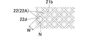
- FIG. 3A is a plan view showing an arrangement state of lattice-type cells on the peripheral surface of the gravure roll.
- FIG. 3B is a perspective view showing the shape of the lattice cell of FIG. 3A.
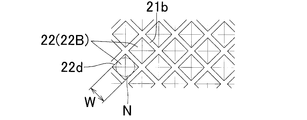
- FIG. 4A is a plan view showing an arrangement state of pyramidal cells on the peripheral surface of the gravure roll.
- FIG. 4B is a perspective view showing the shape of the pyramidal cell of FIG. 4A.
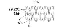
- FIG. 5A is a plan view showing an arrangement state of turtle shell cells on the peripheral surface of the gravure roll.
- FIG. 5B is a perspective view showing the shape of the turtle shell cell of FIG. 5A.
- FIG. 6A is a plan view showing an arrangement state of circular cells on the peripheral surface of the gravure roll.
- FIG. 6B is a perspective view showing the shape of the circular cell of FIG. 6A.
- FIG. 7A is a side view of the cell when the bottom surface of the cell is flat.
- FIG. 7B is a side view of the cell when the bottom surface of the cell has a concave curved surface shape.
- FIG. 7C is a side view of the cell when the bottom surface of the cell has a concave conical surface shape.
- FIG. 8 is a perspective view of the cell when a communication port is provided on the inner peripheral side surface of the cell.
- FIG. 9 is a schematic view when a strip of coating foil is cut.
- FIG. 10 is a schematic side view of a laminate formed by laminating a plurality of coating foils.
- FIG. 11 is a schematic diagram illustrating a process of sintering and integrating the coating foil.
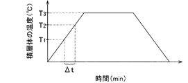
- FIG. 12 is a diagram (graph) showing an example of a temperature curve when the laminate is heated in the step of sintering and integrating the coating foil.
- FIG. 13 is a schematic side view of the composite material of the present embodiment obtained by sintering and integrating the coating foil.
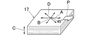
- FIG. 14 is a perspective view of the composite material showing various directions defined by the composite material of the present embodiment.
- FIG. 15 is a side view of the insulating substrate.
- process S1 which obtains coating foil
- process S2 which forms a laminated body
- Step S3 for integrating the coating foil by sintering, and these steps are performed in the order of this description.
- the step S1 of obtaining the coating foil is a step of obtaining the strip-shaped strip 12A of the coating foil 12 (that is, the strip-shaped long coating foil 12) as described in detail with reference to FIG. That is, in this step S1, by applying the coating liquid 5 to the surface 10a of the strip 10A of the metal foil 10, the carbon fiber layer made of the coating liquid 5 on the surface 10a of the strip 10A of the metal foil 10 is applied.
- 11 is a step of obtaining the strip material 12A of the coating foil 12 in which 11 is formed.
- the coating liquid 5 contains the carbon fiber 1, the binder 2, and the binder 2 solvent 3 in a mixed state.
- the process S1 for obtaining the coating foil 12 includes a process S1a for removing the solvent 3 from the carbon fiber layer 11 formed on the surface 10a of the strip 10A of the metal foil 10 (see FIG. 1).
- the step S2 of forming the laminate 15 is a step of forming the laminate 15 in a state where a plurality of coating foils 12 are laminated as shown in FIG.
- the step S3 of sintering and integrating the coating foil 12 is performed by heating the laminated body 15 while pressing it in the laminating direction of the coating foil 12 (that is, the thickness direction of the laminated body 15).
- This process S3 includes process S3a which removes the binder 2 from the laminated body 15 by heating the laminated body 15 (refer FIG. 1).
- process S3 which sinter-integrates the coating foil 12 is equivalent to the desirable example about the process of joining and integrating the coating foil 12 described in the claim.
- the composite material 17 of metal and carbon fiber according to the present embodiment means that a metal is used as a matrix and contains the carbon fiber 1 as a material to be combined with the metal (matrix). . That is, the composite material 17 can be regarded as a metal matrix composite material containing the carbon fiber 1.
- the composite material 17 obtained in this embodiment as shown in FIG. 13, a plurality of metal layers formed of metal foil 10 and carbon fiber layers 11 mainly composed of a large number of carbon fibers 1 are alternately laminated. It was integrated by sintering. A part of the metal of the metal foil 10 penetrates into the carbon fiber layer 11.
- the metal corresponds to a matrix
- the carbon fiber 1 corresponds to a material that is combined with the metal (matrix).
- the composite material 17 can be suitably used as a material for at least one of the plurality of insulating substrate constituting layers 51 to 55 constituting the insulating substrate 50 shown in FIG.
- the insulating substrate 50 is used as an electronic module substrate such as a power module substrate.
- the insulating substrate 50 includes a wiring layer 51, a first stress buffer layer 52, a ceramic layer (insulating layer) 53, a second stress buffer layer 54, and a metal cooling layer 55 as a plurality of constituent layers.
- the wiring layer 51, the first stress buffer layer 52, the ceramic layer 53, the second stress buffer layer 54, and the cooling layer 55 are laminated by a predetermined joining means such as brazing.
- the constituent layers 51 to 55 are joined and integrated.
- An exothermic element 56 (shown by a two-dot chain line) such as an electronic element is mounted on the mounting surface 50a of the insulating substrate 50 by soldering or the like.
- the mounting surface 50 a is composed of the upper surface of the wiring layer 51.
- the cooling layer 55 is a layer for cooling the exothermic element 56, and is a cooling member (including a heat radiating member), for example, and has a plurality of heat radiating fins 55a.
- the cooling layer 55 is made of aluminum or copper.
- the composite material 17 of this embodiment can set the linear expansion coefficient in the planar direction to an intermediate value between the linear expansion coefficient of the metal and the linear expansion coefficient of the ceramic. Therefore, in the insulating substrate 50, it is desirable that at least one of the first and second stress buffer layers 52 and 54 among the constituent layers 51 to 55 is formed of the composite material 17 of the present embodiment.
- the composite material 17 of the present embodiment can be regarded as a metal matrix composite material reinforced with the carbon fiber 1 and has a high Young's modulus. Therefore, it can be suitably used as a material for members that require high mechanical strength.
- the coating liquid 5 used in this step S1 is obtained as follows, for example. As shown in FIG. 2, a large number of carbon fibers 1, a binder 2, and a binder 2 solvent 3 are placed in a mixing container 41, and these are stirred and mixed by a stirring and mixing device 42. Thereby, the coating liquid 5 containing the carbon fiber 1, the binder 2, and the solvent 3 in a mixed state is obtained. At this time, a dispersing agent, an antifoaming agent, a surface adjusting agent, a viscosity adjusting agent and the like may be put into the mixing container 41 and mixed with stirring as necessary.
- the stirring and mixing device 42 is not limited, and a stirrer with a stirring blade, a planetary mixer, a homodisper, a bead mill, or the like can be used.
- a gravure coating apparatus eg, gravure coater 20 is used.
- the gravure coating apparatus 20 is a direct gravure coating apparatus (for example, a direct gravure coater) in detail, and is a coating that attaches the coating liquid 5 to the gravure roll 21, the backup roll 23, and the peripheral surface 21 a of the gravure roll 21.
- the liquid adhesion means 25 etc. are provided.
- a large number of cells (concave portions) 22 are arranged on the peripheral surface 21a of the gravure roll 21 in an orderly manner (see FIGS. 3A, 4A, 5A, and 6A).
- a partition wall 21b is formed between the adjacent cells 22, and each cell 22 is partitioned by the partition wall 21b.
- the backup roll 23 is disposed to face the gravure roll 21.
- the coating liquid adhering means 25 includes a coating liquid pan 26 containing the coating liquid 5, and a part of the circumferential surface 21 a of the gravure roll 21 in the circumferential direction is coated in the pan 26.
- the gravure roll 21 rotates around its central axis while immersed in the working liquid 5, so that the coating liquid 5 is attached to the peripheral surface 21 a of the gravure roll 21.
- the carbon fibers 1 in the coating liquid 5 in the pan 26 are dispersed in the coating liquid 5 so that the fiber directions are random.
- the strip 10A of the metal foil 10 unwound from the unwinding roll 27a is between the gravure roll 21 and the backup roll 23, and in a drying furnace 28 as a drying apparatus. Are sequentially wound in a substantially horizontal direction at a predetermined feed speed, and thereafter wound on a winding roll 27b.
- the feed direction F of the strip 10A of the metal foil 10 is set to the longitudinal direction of the strip 10A of the metal foil 10, and the direction parallel to the feed direction F is the gravure coating device 20 (more specifically, the gravure coating device). 20 is a coating direction of the coating liquid 5 on the surface 10a of the strip 10A of the metal foil 10 by the gravure roll 21).
- the gravure roll 21 is disposed in a manner of traversing the strip 10A of the metal foil 10 across the entire width direction below the strip 10A of the metal foil 10, and the backup roll 23 is
- the strip 10A of the metal foil 10 is arranged on the upper side of the strip 10A of the metal foil 10 so as to traverse the entire width direction. Therefore, the surface 10a of the strip 10A of the metal foil 10 to which the coating solution 5 is applied is the lower surface of the strip 10A of the metal foil 10 in detail.
- the surface 10a of the strip 10A of the metal foil 10 to which the coating solution 5 is applied is not limited to the lower surface of the strip 10A of the metal foil 10, and other examples include The upper surface of the strip 10A of the metal foil 10 may be sufficient, and the upper and lower surfaces of the strip 10A of the metal foil 10 may be sufficient.
- the coating of the coating liquid 5 is performed when the strip 10A of the metal foil 10 passes between the gravure roll 21 and the backup roll 23. That is, when the gravure roll 21 rotates, the coating liquid 5 in the pan 26 adheres to the peripheral surface 21 a of the gravure roll 21 and the coating liquid 5 enters each cell 22. And the excess coating liquid 5 adhering to the peripheral surface 21a of the gravure roll 21 is scraped off by a doctor blade (scraper) 24, and then the peripheral surface 21a of the gravure roll 21 is the surface 10a of the strip 10A of the metal foil 10. , The coating liquid 5 in the cell 22 is transferred to the surface 10a of the strip 10A of the metal foil 10.
- the carbon fiber layer 11 made of the transferred coating liquid 5 is formed on the entire surface 10a of the strip 10A of the metal foil 10 over the entire surface 10a.
- strip material 12A of coating foil 12 in which carbon fiber layer 11 is formed on surface 10a of strip material 10A of metal foil 10 is obtained.
- the rotation direction of the gravure roll 21 is normally set in the same direction as the feed direction F of the strip 10A of the metal foil 10.
- the peripheral speed of the gravure roll 21 is normally set equal to the feed speed of the strip 10 ⁇ / b> A of the metal foil 10.
- the drying furnace 28 heats and drys the carbon fiber layer 11 formed on the surface 10a of the strip 10A of the metal foil 10 (that is, the carbon fiber layer 11 of the strip 12A of the coating foil 12), thereby heating the carbon fiber layer 11. Is for evaporating and removing the solvent 3 contained in the carbon fiber layer 11.
- the shape of the cell 22 is cup-shaped, and in particular, the periphery of the cell 22 is preferably substantially closed over the entire circumference.
- the shape of the cell 22 includes a lattice type 22A (see FIGS. 3A and 3B), a pyramid type 22B (see FIGS. 4A and 4B), a turtle shell type 22C (see FIGS. 5A and 5B), and a circular type 22D (see FIG.
- a lattice type 22A see FIGS. 3A and 3B
- a pyramid type 22B see FIGS. 4A and 4B
- a turtle shell type 22C see FIGS. 5A and 5B
- a circular type 22D see FIG.
- the lattice-type cell 22A is formed in a quadrangular truncated pyramid shape as shown in FIGS. 3A and 3B.
- the pyramid type cell 22B is formed to be recessed in a quadrangular pyramid shape as shown in FIGS. 4A and 4B.
- the tortoiseshell type cell 22C is formed in a hexagonal truncated pyramid shape.
- the circular cell 22D is formed to be recessed in a truncated cone shape as shown in FIGS. 6A and 6B.
- the shape of the bottom surface 22b of the cell 22 is not limited, and may be flat as shown in FIG. 7A, for example.
- 7B may be a concave curved surface (eg, concave spherical surface), or may be a concave conical surface (eg, concave pyramidal surface, concave conical surface) as shown in FIG. 7C.
- a shape in which at least two of these shapes are combined may be used.
- the cell 22 has a shape in which the periphery of the cell 22 is completely closed over the entire circumference, but the present invention is not limited to this, and as shown in FIG. A shape in which a small communication port 22c for allowing a part of the coating liquid 5 in the cell 22 to flow into the adjacent cell 22 is formed in a part of the inner peripheral side surface 22a of the 22 may be used. .
- the size of the cell 22 is large enough for the carbon fiber 1 having an average fiber length to enter the cell 22 in a state substantially parallel to the opening surface of the cell 22, and the average fiber that has entered the cell 22. It is desirable that the long carbon fiber 1 has such a size that it can rotate 360 ° in the inner circumferential direction of the cell 22 in the cell 22. Specifically, the diameter W of the circle N inscribed in the mouth shape of the cell 22 (specifically, the circle N inscribed in the opening peripheral edge 22d of the cell 22) is 1.2 times or more the average fiber length of the carbon fiber 1 It is desirable to be set to.
- the circle N inscribed in the mouth shape of the cell 22 is indicated by a two-dot chain line, and in FIG. 6A, the circle N inscribed in the mouth shape of the cell 22 is the opening peripheral edge 22d of the cell 22. Match.
- the shape of the cell 22 is cup-shaped, and the diameter W of the circle N inscribed in the mouth shape of the cell 22 is set to 1.2 times or more with respect to the average fiber length of the carbon fiber 1.
- the coating liquid 5 in the pan 26 adheres to the peripheral surface 21a of the gravure roll 21 (that is, when the peripheral surface 21a of the gravure roll 21 is immersed in the coating liquid 5 in the pan 26)
- the coating liquid 5 enters the cell 22 so that the fiber direction of the carbon fiber 1 in the cell 5 is random in the inner circumferential direction of the cell 22.
- the carbon fiber 1 in the coating liquid 5 that has entered the cell 22 can rotate in the inner circumferential direction of the cell 22.
- the coating liquid 5 in the cell 22 is transferred to the surface 10 a of the strip 10 ⁇ / b> A of the metal foil 10 as the gravure roll 21 rotates.
- the carbon fiber layer 11 is formed on the surface 10a of the strip 10A of the metal foil 10 so that the fiber direction of the carbon fibers 1 in the surface 10a of the strip 10A of the metal foil 10 is random.
- the coating liquid 5 in the pan 26 on the peripheral surface 21 a of the gravure roll 21 if the shape of the cell 22 is not a cup shape but a hatched type (not shown) well known as the shape of the cell 22, the coating liquid 5 in the pan 26 on the peripheral surface 21 a of the gravure roll 21. , The coating liquid 5 easily enters the cell 22 so that the fiber direction of the carbon fibers 1 in the coating liquid 5 is aligned in one direction along the oblique line direction of the cell 22. In this state, the coating liquid 5 in the cell 22 is transferred to the surface 10 a of the strip 10 ⁇ / b> A of the metal foil 10 as the gravure roll 21 rotates. As a result, the fiber directions of the carbon fibers 1 in the surface 10a of the strip 10A of the metal foil 10 are not random and are easily aligned in one direction. Therefore, the shape of the cell 22 must be a cup shape, not a diagonal type.
- the upper limit of the diameter W of the circle N inscribed in the mouth shape of the cell 22 is not limited and is, for example, 2500 ⁇ m.
- the diameter W of the circle N inscribed in the mouth shape of the cell 22 is such that the shape of the cell 22 is a tortoiseshell type 22C. It is desirable that the size is larger than the case of the circular shape 22D, and it is particularly desirable that it is 1.5 times or more the average fiber length of the carbon fiber 1.
- the strip 10A of the metal foil 10 (the strip 12A of the coating foil 12) is in the drying furnace 28.
- the surface of the carbon fiber layer 11 is not subjected to a leveling treatment for flattening the surface. It is desirable to do so.
- the leveling treatment is a direction in which the edge portion of the leveling member (eg, leveling plate) intersects the feed direction F of the strip 10A of the metal foil 10 (example) :
- the surface of the carbon fiber layer 11 is smoothed by feeding the strip 10A of the metal foil 10 in the feed direction F relative to the leveling member in a state of being applied to the right angle direction). This is a process of leveling the surface of the carbon fiber layer 11 by rubbing with a portion.
- the fiber direction of the carbon fibers 1 in the carbon fiber layer 11 tends to be aligned in the direction along the edge of the leveling member. Therefore, it is desirable that the surface of the carbon fiber layer 11 is not subjected to a leveling process as much as possible.
- the fiber direction of the carbon fiber 1 in the carbon fiber layer 11 in the surface 10a of the strip 10A of the metal foil 10 is reliably maintained in a random state. be able to. Thereby, the physical properties in the planar direction of the composite material 17 can be ensured.
- the carbon fiber 1 can be used as long as it is a fibrous carbon particle, and specifically includes, for example, a PAN-based carbon fiber, a pitch-based carbon fiber, and a carbon nanofiber (eg, vapor-grown carbon fiber, carbon nanotube).
- a PAN-based carbon fiber e.g., PAN-based carbon fiber
- a pitch-based carbon fiber e.g., PAN-based carbon fiber
- a carbon nanofiber eg, vapor-grown carbon fiber, carbon nanotube.
- One kind of carbon fiber selected from the group or two or more kinds of mixed carbon fibers are used.
- pitch-based carbon fibers it is particularly desirable to use pitch-based carbon fibers.
- the reason is that the thermal conductivity in the fiber direction of the pitch-based carbon fiber is larger than that of the PAN-based carbon fiber, so that the composite material 17 having a higher thermal conductivity can be obtained.
- the length of the carbon fiber 1 is not limited, and the average fiber length of the carbon fiber 1 is particularly preferably 1 mm or less.
- the reason is that the carbon fiber layer 11 can be formed on the surface 10a of the strip 10A of the metal foil 10 so that the fiber direction of the carbon fiber 1 in the surface 10a of the strip 10A of the metal foil 10 is surely random. It is. Thereby, the physical properties in the planar direction of the composite material 17 can be further ensured.
- the lower limit of the length of the carbon fiber 1 is not limited, and usually the lower limit of the average fiber length of the carbon fiber 1 is 10 ⁇ m.
- the fiber diameter of the carbon fiber 1 is not limited, and the average fiber diameter of the carbon fiber 1 is, for example, 0.1 nm to 20 ⁇ m.
- the carbon fiber 1 is a PAN-based carbon fiber or a pitch-based carbon fiber
- the carbon fiber 1 is, for example, a chopped fiber or a milled fiber
- the average fiber diameter is, for example, 5 ⁇ m to 15 ⁇ m.
- the carbon fiber 1 is a vapor grown carbon nanofiber
- the average fiber diameter of the carbon fiber 1 is, for example, 0.1 nm to 20 ⁇ m.
- the binder 2 gives the carbon fiber 1 adhesion to the surface 10 a of the strip 10 ⁇ / b> A of the metal foil 10, whereby the carbon fiber 1 in the carbon fiber layer 11 falls off from the surface 10 a of the strip 10 ⁇ / b> A of the metal foil 10. It is for suppressing this, and is usually made of a resin.
- the binder 2 when the binder 2 is heated, it easily becomes an organic sintered residue or an amorphous carbide, which causes a decrease in the thermal conductivity of the composite material 17 as a residue of the binder 2. Therefore, it is desirable to use the binder 2 that does not carbonize at a temperature of 200 ° C. to 450 ° C. in a non-oxidizing atmosphere and disappears by sublimation or decomposition.
- a binder 2 an acrylic resin, a polyethylene glycol resin, a butylene rubber resin, a phenol resin, a cellulose resin, or the like is preferably used. These binders 2 are generally solid at room temperature.
- Solvent 3 is desirably one that dissolves binder 2 at room temperature, and water, alcohol solvents, hydrocarbon solvents, ester solvents, ether solvents, and the like are preferably used.
- the coating solution 5 desirably contains the carbon fiber 1 and the binder 2 in a mass ratio of 75:25 to 99.5: 0.5.
- the carbon fiber 1 can be reliably attached to the surface 10a of the strip 10A of the metal foil 10 in the step S1 to obtain the coating foil 12, and the binder 2 can be surely attached in the step S3a of removing the binder 2.
- the coating solution 5 contains the carbon fiber 1 and the binder 2 in a mass ratio of 80:20 to 99: 1.
- step S1 of obtaining the coating foil 12 the coating solution 5 is applied to the surface 10a of the strip 10A of the metal foil 10 so that the coating amount of the carbon fiber 1 contained in the carbon fiber layer 11 is 40 g / m 2 or less. It is desirable to apply. The reason is as follows.
- the metal of the metal foil 10 sufficiently penetrates substantially all of the voids in the carbon fiber layer 11 and is disposed on both sides of the carbon fiber layer 11 therebetween. 10 are sufficiently sintered. Thereby, the intensity
- the coating liquid 5 is applied to the surface 10a of the strip 10A of the metal foil 10 so that the volume of the carbon fiber 1 in the obtained composite material 17 is less than 50% with respect to the total volume of the composite material 17. It is desirable that the metal of the metal foil 10 can be reliably infiltrated into the carbon fiber layer 11 in the step S3 of sintering and integrating the coating foil 12, and the coating foil 12 is securely and firmly Sintering can be integrated.
- the linear expansion coefficient of the composite material 17 in the planar direction is that of the ceramic layer 53 of the insulating substrate 50. It is desirable to set the ratio of the volume of the metal foil 10 and the volume of the carbon fiber 1 so as to be an intermediate value between the linear expansion coefficient and the linear expansion coefficient of the wiring layer 51.
- the linear expansion coefficient in the planar direction of the composite material 17 is equal to the linear expansion coefficient of the ceramic layer 53 of the insulating substrate 50 and the cooling layer. It is desirable to set the ratio of the volume of the metal foil 10 and the volume of the carbon fiber 1 so as to be an intermediate value with the linear expansion coefficient of 55.
- the linear expansion coefficient in the planar direction of the composite material 17 is used as a ceramic (aluminum nitride, alumina, silicon carbide, etc.) wire often used as the material of the ceramic layer 53.
- the coefficient of expansion eg about 3 ⁇ 10 ⁇ 6 / K to 5 ⁇ 10 ⁇ 6 / K
- the coefficient of linear expansion of aluminum often used as the material for the cooling layer 55 (about 23 ⁇ 10 ⁇ 6 / K)
- the volume of the carbon fiber 1 is set to 10% or more and less than 50% with respect to the total volume of the composite material 17. It is desirable.
- the metal foil 10 (the strip 10A of the metal foil 10) is not limited to that material as long as it can withstand coating.
- the metal foil 10 is desirably at least one of an aluminum foil and a copper foil. The reason is that the composite material 17 having a high thermal conductivity can be obtained with certainty.
- the material of the aluminum foil is not limited, and A1000 series, A3000 series, A6000 series, and the like are used.
- the material of the aluminum foil is appropriately selected from a plurality of types of aluminum materials so that the physical properties (thermal conductivity, linear expansion coefficient, etc.) of the obtained composite material 17 become desired set values.
- the type and material of the copper foil are not limited, and an electrolytic copper foil, a rolled copper foil, or the like is used.
- the material of the copper foil is appropriately selected from a plurality of types of copper materials so that the physical properties of the obtained composite material 17 are set to desired values.
- the thickness of the metal foil 10 is not limited, and the thickness of the metal foil 10 can be selected so that the physical properties of the obtained composite material 17 become a desired set value.
- the thinnest thickness of the commercially available metal foil (aluminum foil, copper foil) 10 is 6 ⁇ m
- the lower limit of the thickness of the metal foil 10 is easily 6 ⁇ m. It is particularly desirable in that it is available.
- the upper limit of the thickness of the metal foil 10 is usually 100 ⁇ m, and particularly preferably about 50 ⁇ m.
- the width of the metal foil 10 is not limited, and is set according to the application of the composite material 17, for example, 10 mm to 1200 mm.
- the step S1a for removing the solvent 3 is performed by passing the strip 12A of the coating foil 12 through the drying furnace 28 as shown in FIG. That is, when the strip 12A of the coating foil 12 passes through the drying furnace 28, the carbon fiber layer 11 is heated and dried by the drying furnace 28, whereby the solvent 3 contained in the carbon fiber layer 11 is changed to the carbon fiber layer. 11 is removed by evaporation. Thereafter, the strip 12A of the coating foil 12 is wound around the winding roll 27b.
- the conditions for removing the solvent 3 by the drying furnace 28 are not limited as long as the solvent 3 contained in the carbon fiber layer 11 can be removed from the carbon fiber layer 11 by evaporation. Drying conditions of 250 ° C. and drying time of 1 min to 120 min can be applied as solvent 3 removal conditions.
- Step S2 of Forming Laminate 15> In the step of forming the laminated body 15, as shown in FIG. 9, the strip material 12 ⁇ / b> A of the coating foil 12 unwound from the winding roll 27 b is cut into a predetermined shape by a cutting machine 29. As a result, a plurality of coating foils 12 having a predetermined shape (eg, substantially rectangular shape) are cut out from the strip 12 ⁇ / b> A of the coating foil 12. And as shown in FIG. 10, the laminated body 15 of the state by which the coating foil 12 was laminated
- the laminated body 15 thus formed is used as a preform (sintered material).
- the number of laminated coating foils 12 is not limited, and is set according to the desired thickness of the composite material 17, for example, 5 to 1000.
- step S3 for integrating the coating foil 12 by sintering the laminate 15 is disposed in the sintering chamber 31 of a sintering apparatus (joining apparatus) 30 such as a pressure heating sintering apparatus.
- the laminate 15 is heated at a predetermined sintering temperature while being pressed in the lamination direction of the coating foil 12 (that is, the thickness direction of the laminate 15) in a predetermined sintering atmosphere by the sintering device 30.
- the laminated body 15 is sintered, that is, the coating foil 12 is sintered and integrated. Thereby, as shown in FIG. 13, the composite material 17 of this embodiment is obtained.
- the laminate 15 is pressurized and heated, so that the carbon fiber layer 11 is compressed in the thickness direction, and a part of the metal of the metal foil 10 penetrates into the carbon fiber layer 11 to form carbon fibers. It fills in the fine space
- the theoretical density of the composite material 17 is the density of the composite material 17 when the composite material 17 is formed only of the metal of the metal foil 10 and the carbon fiber 1 and there is no void inside the composite material 17. Means.
- a hot press apparatus eg, vacuum hot press apparatus
- a discharge plasma sintering apparatus or the like is preferably used.
- the pressurization to the laminate 15 is performed by, for example, pressing the laminate 15 with a pair of punches 32 and 32 provided in the sintering apparatus 30.
- the sintering atmosphere is preferably a non-oxidizing atmosphere.
- the non-oxidizing atmosphere includes an inert gas atmosphere (eg, nitrogen gas atmosphere, argon gas atmosphere), a vacuum atmosphere, and the like.
- the sintering temperature means a temperature at which the coating foil 12 is sintered and integrated (joined integrated). Specifically, the sintering temperature is set to a temperature equal to or lower than the melting point of the metal of the metal foil 10, and in particular, set to a temperature between the melting point of the metal of the metal foil 10 and a temperature about 50 ° C. lower than the melting point. It is desirable that the coating foil 12 can be reliably sintered and integrated. When the metal foil 10 is, for example, an aluminum foil, the sintering temperature is preferably set in the range of 550 ° C. to 620 ° C.
- the pressure applied to the laminate 15 is not limited, and may be a pressure that lightly presses the laminate 15. Furthermore, since the fluidity of the metal of the metal foil 10 may be improved when the laminate 15 is pressurized when heated to the laminate 15, the metal of the metal foil 10 is removed from the laminate 15 by the pressurization to the laminate 15. It is particularly desirable to pressurize with a pressing force that does not flow out, or pressurize the laminated body 15 in a mold (not shown) so that the metal of the metal foil 10 does not flow out of the laminated body 15.
- the gap portion becomes an internal defect of the composite material 17. Therefore, in order to suppress the occurrence of this defect, it is desirable to pressurize the laminate 15 as a sintering atmosphere in a vacuum atmosphere and / or pressurize the laminate 15 in the mold.
- the step S3a for removing the binder 2 is a process in which the laminate 15 in the step S3 for sintering and integrating the coating foil 12 by the sintering apparatus 30 is heated from about room temperature as the initial temperature to the sintering temperature. Is performed by the sintering apparatus 30.
- the binder 2 removal step S3a in this case will be described below.
- FIG. 12 is a diagram (graph) showing an example of a temperature curve when the laminated body 15 is heated in the step S3 of sintering and integrating the coating foil 12.
- T1 to T2 (where T1 ⁇ T2) in the figure is a range in which the binder 2 contained in the carbon fiber layer 11 of the coating foil 12 of the laminate 15 disappears due to sublimation or decomposition. Usually, it is 200 ° C. to 450 ° C.
- T3 is a sintering temperature and is higher than T2 (that is, T3> T2).
- the temperature of the laminated body 15 during the heating of the laminated body 15 by the sintering device 30 so that the temperature of the laminated body 15 rises from about room temperature to the sintering temperature T3. Is within the range of T1 to T2, the binder 2 disappears by sublimation or decomposition and is removed from the laminate 15 (more specifically, the carbon fiber layer 11 of the coating foil 12 of the laminate 15).
- the time ⁇ t during which the temperature of the laminate 15 is within the temperature range of T1 to T2 is not limited as long as the binder 2 can be removed from the laminate 15, and the temperature of the laminate 15 is increased by the sintering device 30. It is set according to the temperature rate, the total amount of the binder 2 contained in the laminate 15, the thickness of the laminate 15 (eg, the number of laminated coating foils 12), the sintering atmosphere, etc., and is usually 10 min. Set as above.
- the time ⁇ t is lengthened by temporarily stopping the temperature increase or by gradually increasing the temperature increase rate, thereby reliably removing the binder 2. It is also possible to do so.
- the number of manufacturing steps of the composite material 17 is achieved by performing the step S3a for removing the binder 2 while heating the laminated body 15 in the step S3 for sintering and integrating the coating foil 12 to the sintering temperature T3. Therefore, the composite material 17 can be easily manufactured.
- the present invention does not exclude that the step S3a for removing the binder 2 is performed independently from the step S3 for sintering and integrating (joining integration) the coating foil 12 by the sintering device 30.
- the step S3a for removing the binder 2 may be performed after the step S2 for forming the laminate 15 and before the step S3 for sintering and integrating (joining integration) the coating foil 12.
- the step S3a for removing the binder 2 may be performed after the step S2 for forming the laminate 15 and before the step S3 for sintering and integrating (joining integration) the coating foil 12.
- the laminate 15 is disposed in a non-oxidizing atmosphere. It is desirable to set the temperature of the laminated body 15 to 300 ° C. or lower. The reason is that oxidation consumption of the carbon fiber 1 can be reliably suppressed, and oxidation of the aluminum foil can be reliably suppressed when the metal foil 10 is an aluminum foil.
- the coating apparatus for applying the coating liquid 5 to the surface 10a of the strip 10A of the metal foil 10 is the gravure coating apparatus 20, and the gravure roll of the gravure coating apparatus 20
- the shape of the 21 cells 22 is cup-shaped, and the diameter W of the circle N inscribed in the mouth shape of the cells 22 is set to 1.2 times or more the average fiber length of the carbon fibers 1.
- the carbon fiber layer 11 can be formed on the surface 10a of the strip 10A of the metal foil 10 so that the fiber direction of the carbon fiber 1 in the surface 10a of the strip 10A of the metal foil 10 is random. Therefore, the physical properties (thermal conductivity, linear expansion coefficient, etc.) of the composite material 17 in the planar direction can be made uniform.
- the arrow “P” in FIG. 14 indicates the coating direction of the coating liquid 5 on the surface 10a of the strip 10A of the metal foil 10 by the gravure coating apparatus 20.
- the length direction A of the composite material 17 means a direction parallel to the coating direction P.
- the width direction B of the composite material 17 means a direction perpendicular to the length direction A of the composite material 17 in the plane of the composite material 17.
- the oblique direction D of the composite material 17 means a direction oblique by 45 ° with respect to the length direction A of the composite material 17 in the plane of the composite material 17.
- “C” is the thickness direction of the composite material 17, and the thickness direction D coincides with the lamination direction of the coating foil 12.
- the composite material 17 of the present embodiment includes the physical properties of the composite material 17 in the longitudinal direction A, the physical properties of the composite material 17 in the width direction B, and the physical properties of the composite material 17 in the oblique direction D. They are almost equal to each other. Therefore, in the insulating substrate 50 shown in FIG. 15, by forming at least one constituent layer of the plurality of constituent layers 51 to 55 constituting the insulating substrate 50 with the composite material 17, it is possible to prevent temperature changes such as a cooling cycle. Thus, an insulating substrate having high reliability can be obtained, and therefore, cracking and peeling of the insulating substrate 50 due to thermal strain can be reliably suppressed.
- the coating apparatus is not a gravure coating apparatus 20, but a roll coater (eg, roll coater), a die coater (eg, die coater) or a knife coater (eg, knife coater), a metal foil
- a roll coater eg, roll coater
- a die coater eg, die coater
- a knife coater eg, knife coater
- the metal foil to which the coating liquid is applied in the step of obtaining the coating foil is not limited to the strip of metal foil as shown in the above embodiment. It may be a metal foil that is not in the shape of a strip (eg, a substantially rectangular metal foil having a preset length dimension and width dimension).
- the gravure coating apparatus is particularly preferably a direct gravure coating apparatus as shown in the above embodiment, but in addition, for example, an offset gravure coating apparatus (eg, offset gravure coater) Also good.
- an offset gravure coating apparatus eg, offset gravure coater
- Example 1 a composite material of aluminum and carbon fiber was produced by the following procedure.
- Carbon fiber with an average fiber length of 150 ⁇ m and average fiber diameter of 10 ⁇ m (Nippon Graphite Fiber Co., Ltd .: XN-100) and polyethylene oxide with an average molecular weight of 700,000 as a binder (manufactured by Meisei Chemical Industry Co., Ltd .: Alcox) )
- a 3% by weight aqueous solution of E-45), isopropyl alcohol as a solvent, water, a dispersant, and a surface conditioner were mixed with stirring to obtain a coating solution.
- the mass of the binder contained in the coating liquid was 10% in terms of solid content with respect to the mass of the carbon fiber.
- the viscosity of the coating solution was 1000 mPa ⁇ s at 25 ° C.
- a coating liquid is applied to the entire lower surface of a strip of aluminum foil (material: A1N30) having a thickness of 20 ⁇ m and a width of 500 mm by a gravure coater (specifically, a direct gravure coater) at a coating speed of 20 m / min.
- a gravure coater specifically, a direct gravure coater
- the composition of the gravure coater was as follows.
- the mesh on the peripheral surface of the gravure roll provided in the gravure coater was # 25, the cell shape was a lattice shape, and the diameter of the circle inscribed in the cell mouth shape was 1000 ⁇ m.
- the solvent removal conditions in the drying furnace were a drying temperature of 180 ° C. and a drying time of 2 minutes.
- the strip of the coating foil was cut into a square shape (its dimensions: 50 mm long ⁇ 50 mm wide), whereby a plurality of square coated foils were cut out from the strip of the coating foil. And the laminated body was formed by laminating
- the laminate is sintered by heating at a predetermined sintering temperature while pressing the laminate in the laminating direction of the coating foil in a vacuum atmosphere by a discharge plasma sintering apparatus as a pressure heating sintering apparatus. That is, the coating foil was sintered and integrated, thereby obtaining a composite material of aluminum and carbon fiber.
- the thickness of the composite material was 4 mm.
- the sintering temperature was 550 ° C.
- the holding time (sintering time) of the sintering temperature was 3 h
- the temperature rising rate from room temperature was 50 ° C./min
- the pressure applied to the laminate was 15 MPa
- the degree of vacuum was 5 Pa.
- the temperature rise was temporarily stopped while the laminate was heated from room temperature to a sintering temperature of 550 ° C., and the binder was removed from the laminate.
- the binder removal conditions applied at this time were as follows.
- the heating temperature of the laminate for removing the binder was 380 ° C., and the heating time was 30 min.
- the obtained composite material is in a state in which a plurality of aluminum layers and carbon fiber layers formed from aluminum foil are alternately laminated, and the aluminum sufficiently penetrates into the carbon fiber layer so that the carbon fiber layer There were almost no voids inside, and the density of the composite material was 99% of the theoretical density of the composite material.
- Example 2 a composite material of aluminum and carbon fiber was produced by the following procedure.
- Carbon fiber (Mitsubishi Resin Co., Ltd. product: K223HM) having an average fiber length of 200 ⁇ m and an average fiber diameter of 10 ⁇ m, an acrylic resin as a binder, propylene glycol ethyl ether acetate as a solvent, a dispersant, and a surface conditioner are stirred. This was mixed to obtain a coating solution.
- the mass of the binder contained in the coating liquid was 20% in terms of solid content with respect to the mass of the carbon fiber.
- the viscosity of the coating solution was 700 mPa ⁇ s at 25 ° C.
- a coating solution was applied to the lower surface of a strip of aluminum foil (material: A1N30) having a thickness of 20 ⁇ m and a width of 280 mm by a gravure coater at a coating speed of 30 m / min.
- a strip of coated foil having a carbon fiber layer formed on the lower surface of the strip of foil was obtained.
- the strip of the coating foil was passed through a drying furnace to evaporate and remove the solvent from the carbon fiber layer.
- the coating amount of the carbon fiber contained in the carbon fiber layer after removing the solvent from the carbon fiber layer was 20 g / m 2 .
- the composition of the gravure coater was as follows.
- the mesh on the peripheral surface of the gravure roll provided in the gravure roll was # 30, the shape of the cell was a pyramid, and the diameter of the circle inscribed in the mouth shape of the cell was 830 ⁇ m.
- the solvent removal conditions in the drying furnace were a drying temperature of 170 ° C. and a drying time of 1 min.
- the strip of the coating foil was cut into a square shape (its dimensions: 50 mm long ⁇ 50 mm wide), whereby a plurality of square coated foils were cut out from the strip of the coating foil. And the laminated body was formed by laminating
- the laminated body is sintered by heating at a predetermined sintering temperature while pressing the laminated body in the lamination direction of the coating foil in a vacuum atmosphere by a vacuum hot press apparatus as a pressure heating sintering apparatus.
- the coating foil was sintered and integrated to obtain a composite material of aluminum and carbon fiber.
- the thickness of the composite material was 4 mm.
- the sintering temperature is 600 ° C.
- the sintering temperature holding time (sintering time) is 6 hours
- the heating rate from room temperature is 20 ° C./min
- the pressure applied to the laminate is 15 MPa
- the degree of vacuum is 5 ⁇ 10 ⁇ 1. Pa.
- the rate of temperature rise from room temperature (20 ° C./min) is slower than that of Example 1 (50 ° C./min), and the laminate is taken from room temperature.
- the binder was removed from the laminate without temporarily stopping the heating during the heating to the sintering temperature of 600 ° C.
- the obtained composite material is in a state in which a plurality of aluminum layers and carbon fiber layers formed from aluminum foil are alternately laminated, and the aluminum sufficiently penetrates into the carbon fiber layer so that the carbon fiber layer There were almost no voids inside, and the density of the composite material was 99% of the theoretical density of the composite material.
- Comparative Example 1 a composite material of aluminum and carbon fiber was produced by the following procedure.
- Example 2 The same coating solution as that used in Example 1 was prepared. Then, a coating liquid was applied over the entire lower surface of the strip of aluminum foil (its material: A1N30) having a thickness of 20 ⁇ m and a width of 150 mm using a test applicator, whereby the strip of aluminum foil A strip of coated foil having a carbon fiber layer formed on the lower surface was obtained. Then, the strip of the coating foil was passed through a drying furnace to evaporate and remove the solvent from the carbon fiber layer. The coating amount of the carbon fiber contained in the carbon fiber layer after removing the solvent from the carbon fiber layer was 30 g / m 2 .
- the solvent removal conditions in the drying furnace were a drying temperature of 100 ° C. and a drying time of 30 minutes.
- the strip of the coating foil was cut into a square shape (its dimensions: 50 mm long ⁇ 50 mm wide), whereby a plurality of square coated foils were cut out from the strip of the coating foil.
- the laminated body was formed by laminating
- the laminate is sintered by heating at a predetermined sintering temperature while pressing the laminate in the laminating direction of the coating foil in a vacuum atmosphere by a discharge plasma sintering apparatus as a pressure heating sintering apparatus. That is, the coating foil was sintered and integrated, thereby obtaining a composite material of aluminum and carbon fiber.
- the thickness of the composite material was 4 mm.
- the obtained composite material is in a state in which a plurality of aluminum layers and carbon fiber layers formed from aluminum foil are alternately laminated, and the aluminum sufficiently penetrates into the carbon fiber layer so that the carbon fiber layer There were almost no voids inside, and the density of the composite material was 99% of the theoretical density of the composite material.
- Comparative example 2 In Comparative Example 2, aluminum and carbon were used in the same production process and production conditions as in Comparative Example 1 except that a laminate was formed by laminating 200 coating foils so that the coating directions were alternately perpendicular. A composite with fiber was obtained.
- the obtained composite material is in a state in which a plurality of aluminum layers and carbon fiber layers formed from aluminum foil are alternately laminated, and the aluminum sufficiently penetrates into the carbon fiber layer so that the carbon fiber layer There were almost no voids inside, and the density of the composite material was 99% of the theoretical density of the composite material.
- the thermal conductivities in the A direction, the B direction, and the D direction are substantially equal to each other, and the linear expansion coefficients in the A direction, the B direction, and the D direction are also substantially equal to each other. It was equal. Therefore, it was confirmed that the physical properties (thermal conductivity, linear expansion coefficient) in the planar direction of the composite materials of Examples 1 and 2 were substantially uniform.
- the thermal conductivities in the A direction, the B direction, and the D direction were different from each other, and the linear expansion coefficients in the A direction, the B direction, and the D direction were also different from each other.
- the thermal conductivity in the A direction and the B direction are substantially equal to each other, but the thermal conductivity in the D direction is different from the thermal conductivity in the A direction and the B direction.
- the linear expansion coefficients in the direction are equal to each other, but the linear expansion coefficients in the D direction are different from the linear expansion coefficients in the A direction and the B direction. Therefore, it was confirmed that the physical properties (thermal conductivity, linear expansion coefficient) in the planar direction of the composite materials of Comparative Examples 1 and 2 were poor in uniformity.
- the composite materials of Examples 1 and 2 and Comparative Examples 1 and 2 were each cut into a square shape (its dimensions: 30 mm length ⁇ 30 mm width), and each surface was square (its dimensions: 20 mm length ⁇ 20 mm width ⁇ thickness).
- 1.6 mm thick) silicon carbide plates (SiC plates) were joined in a laminated manner by soldering, whereby the joined bodies of Examples 1 and 2 and Comparative Examples 1 and 2 were obtained. Then, a cooling / heating cycle test of ⁇ 40 ° C. to 80 ° C. was repeated 3000 cycles for each joined body.
- the term present invention or inventory should not be construed inappropriately as identifying criticality, nor should it be construed as inappropriately applied across all aspects or all embodiments ( That is, it should be understood that the present invention has numerous aspects and embodiments) and should not be construed inappropriately to limit the scope of the present application or the claims.
- the term “embodiment” is also used to describe any aspect, feature, process or step, any combination thereof, and / or any part thereof. It is done. In some examples, various embodiments may include overlapping features.
- the abbreviations “e.g.,” and “NB” may be used, meaning “for example” and “careful”, respectively.
- the present invention can be used in a method for manufacturing a composite material of metal and carbon fiber and a method for manufacturing an insulating substrate.
Landscapes
- Chemical & Material Sciences (AREA)
- Engineering & Computer Science (AREA)
- Materials Engineering (AREA)
- Mechanical Engineering (AREA)
- Metallurgy (AREA)
- Organic Chemistry (AREA)
- Physics & Mathematics (AREA)
- Crystallography & Structural Chemistry (AREA)
- Thermal Sciences (AREA)
- Fluid Mechanics (AREA)
- Laminated Bodies (AREA)
- Manufacture Of Alloys Or Alloy Compounds (AREA)
Abstract
Description
前記塗工箔が複数積層された状態の積層体を形成する工程と、
前記積層体を加熱することにより前記積層体から前記バインダーを除去し、そして前記前記積層体を前記塗工箔の積層方向に加圧しながら加熱することにより前記塗工箔を接合一体化する工程と、を具備し、
前記グラビアロールの前記セルの形状がカップ状であり、且つ、前記セルの口形状に内接する円の直径が前記炭素繊維の平均繊維長に対して1.2倍以上に設定されている、金属と炭素繊維との複合材の製造方法。
複数の構成層のうち少なくとも一つの構成層は金属と炭素繊維との複合材で形成されており、
前記複合材を前項1~6のいずれかに記載の金属と炭素繊維との複合材の製造方法により製造する、絶縁基板の製造方法。
本工程S1で使用される塗工液5は例えば次のようにして得られる。図2に示すように、多数の炭素繊維1とバインダー2とバインダー2用溶剤3とを混合容器41内に入れてこれらを撹拌混合装置42により撹拌混合する。これにより、炭素繊維1とバインダー2と溶剤3とを混合状態に含有した塗工液5が得られる。このとき、分散剤、消泡剤、表面調整剤、粘度調整剤なども必要に応じて混合容器41内に入れて撹拌混合しても良い。
積層体15を形成する工程では、図9に示すように、巻取りロール27bから巻き解かれた塗工箔12の条材12Aを切断機29により所定形状に切断する。これにより、塗工箔12の条材12Aから所定形状(例:略四角形状)の塗工箔12を複数切り出す。そして、図10に示すように、塗工箔12を複数積層することにより、塗工箔12が複数積層された状態の積層体15を形成する。あるいは、図示していないが巻取りロール27bから巻き解かれた塗工箔12の条材12Aをロール状に巻くことにより、塗工箔12が複数積層された状態の積層体15を形成しても良い。
塗工箔12を焼結一体化する工程S3では、図11に示すように、加圧加熱焼結装置などの焼結装置(接合装置)30の焼結室31内に積層体15を配置し、そして焼結装置30によって所定の焼結雰囲気中にて積層体15を塗工箔12の積層方向(即ち積層体15の厚さ方向)に加圧しながら所定の焼結温度で加熱することにより積層体15を焼結し即ち塗工箔12を焼結一体化する。これにより、図13に示すように本実施形態の複合材17が得られる。
実施例1では、アルミニウムと炭素繊維との複合材を次の手順で製造した。
実施例2では、アルミニウムと炭素繊維との複合材を次の手順で製造した。
比較例1では、アルミニウムと炭素繊維との複合材を次の手順で製造した。
比較例2では、塗工箔を塗工方向が交互に直角になるように200枚積層することで積層体を形成したこと以外は、上記比較例1と同じ製造工程及び製造条件でアルミニウムと炭素繊維との複合材を得た。
上記実施例1、2、比較例1及び2の複合材についてそれぞれ熱伝導率と線膨張係数を測定した。その結果を表1に示した。

上記実施例1、2、比較例1及び2の複合材に対してそれぞれ以下の冷熱サイクル試験を行った。
2:バインダー
3:溶剤
5:塗工液
10:金属箔
10A:金属箔の条材
11:炭素繊維層
12:塗工箔
12A:塗工箔の条材
15:積層体
17:金属と炭素繊維との複合材
20:グラビア塗工装置
21:グラビアロール
22:セル
28:乾燥炉
30:焼結装置
Claims (7)
- 炭素繊維とバインダーと前記バインダー用溶剤とを混合状態に含有する塗工液を、周面に多数のセルが設けられたグラビアロールを備えたグラビア塗工装置により金属箔の表面に塗工することにより、前記金属箔の表面上に炭素繊維層が形成された塗工箔を得る工程と、
前記塗工箔が複数積層された状態の積層体を形成する工程と、
前記積層体を加熱することにより前記積層体から前記バインダーを除去し、そして前記前記積層体を前記塗工箔の積層方向に加圧しながら加熱することにより前記塗工箔を接合一体化する工程と、を具備し、
前記グラビアロールの前記セルの形状がカップ状であり、且つ、前記セルの口形状に内接する円の直径が前記炭素繊維の平均繊維長に対して1.2倍以上に設定されている、金属と炭素繊維との複合材の製造方法。 - 前記塗工箔を得る工程は、前記金属箔の表面上に形成された前記炭素繊維層から前記溶剤を除去する工程を含んでいる請求項1記載の金属と炭素繊維との複合材の製造方法。
- 前記塗工箔を得る工程は、前記金属箔の表面上に形成された前記炭素繊維層の表面に摺り均し処理を施さないで前記炭素繊維層から前記溶剤を除去する工程を含んでいる請求項1記載の金属と炭素繊維との複合材の製造方法。
- 前記塗工箔を接合一体化する工程では、前記積層体の温度が前記塗工箔を接合一体化する温度まで上昇するように前記積層体を加熱する途中で前記積層体から前記バインダーを除去する請求項1~3のいずれかに記載の金属と炭素繊維との複合材の製造方法。
- 前記セルの形状は、格子型、ピラミッド型、亀甲型及び円型からなる群より選択される少なくとも一つである請求項1~4のいずれかに記載の金属と炭素繊維との複合材の製造方法。
- 前記金属箔はアルミニウム箔及び銅箔のうち少なくとも一方である請求項1~5のいずれかに記載の金属と炭素繊維との複合材の製造方法。
- 積層状に一体化される複数の絶縁基板構成層を備えた絶縁基板の製造方法であって、
複数の構成層のうち少なくとも一つの構成層は金属と炭素繊維との複合材で形成されており、
前記複合材を請求項1~6のいずれかに記載の金属と炭素繊維との複合材の製造方法により製造する、絶縁基板の製造方法。
Priority Applications (4)
| Application Number | Priority Date | Filing Date | Title |
|---|---|---|---|
| DE112016006013.0T DE112016006013T5 (de) | 2015-12-24 | 2016-08-25 | Verfahren zur Herstellung eines Metall-Kohlenstofffaser-Verbundmaterials |
| US16/065,680 US20190001652A1 (en) | 2015-12-24 | 2016-08-25 | Method for producing metal-carbon fiber composite material |
| JP2017557733A JPWO2017110140A1 (ja) | 2015-12-24 | 2016-08-25 | 金属と炭素繊維との複合材の製造方法 |
| CN201680069366.1A CN108291290B (zh) | 2015-12-24 | 2016-08-25 | 金属与碳纤维的复合材料的制造方法 |
Applications Claiming Priority (2)
| Application Number | Priority Date | Filing Date | Title |
|---|---|---|---|
| JP2015-251416 | 2015-12-24 | ||
| JP2015251416 | 2015-12-24 |
Publications (1)
| Publication Number | Publication Date |
|---|---|
| WO2017110140A1 true WO2017110140A1 (ja) | 2017-06-29 |
Family
ID=59089998
Family Applications (1)
| Application Number | Title | Priority Date | Filing Date |
|---|---|---|---|
| PCT/JP2016/074733 Ceased WO2017110140A1 (ja) | 2015-12-24 | 2016-08-25 | 金属と炭素繊維との複合材の製造方法 |
Country Status (5)
| Country | Link |
|---|---|
| US (1) | US20190001652A1 (ja) |
| JP (1) | JPWO2017110140A1 (ja) |
| CN (1) | CN108291290B (ja) |
| DE (1) | DE112016006013T5 (ja) |
| WO (1) | WO2017110140A1 (ja) |
Cited By (2)
| Publication number | Priority date | Publication date | Assignee | Title |
|---|---|---|---|---|
| JP2020089819A (ja) * | 2018-12-04 | 2020-06-11 | 昭和電工株式会社 | 粒子塗工箔の製造方法及び金属−粒子複合材の製造方法 |
| JP2022132461A (ja) * | 2018-12-04 | 2022-09-08 | 昭和電工株式会社 | 粒子塗工箔の製造方法及び金属-粒子複合材の製造方法 |
Families Citing this family (4)
| Publication number | Priority date | Publication date | Assignee | Title |
|---|---|---|---|---|
| JP7342881B2 (ja) * | 2018-11-21 | 2023-09-12 | 株式会社レゾナック | アルミニウム-炭素粒子複合材及びその製造方法 |
| CN112403806A (zh) * | 2019-08-20 | 2021-02-26 | 北京卫蓝新能源科技有限公司 | 一种制备大宽幅超薄金属锂带的凹版涂布装置及其方法 |
| CN117067712A (zh) * | 2023-06-19 | 2023-11-17 | 常州威斯双联科技有限公司 | 一种屏蔽导热性能优良的高强度纤维复合板及其制备方法 |
| WO2025076798A1 (zh) * | 2023-10-13 | 2025-04-17 | 行富投资有限公司 | 连续纤维铝复合材料与制造方法 |
Citations (2)
| Publication number | Priority date | Publication date | Assignee | Title |
|---|---|---|---|---|
| JP2008144045A (ja) * | 2006-12-11 | 2008-06-26 | Teijin Fibers Ltd | 繊維状導電性フィラーおよび導電性樹脂組成物および導電性構造体 |
| JP2015025158A (ja) * | 2013-07-25 | 2015-02-05 | 昭和電工株式会社 | 金属と炭素繊維との複合材及びその製造方法 |
Family Cites Families (5)
| Publication number | Priority date | Publication date | Assignee | Title |
|---|---|---|---|---|
| CH581836A5 (ja) | 1974-08-20 | 1976-11-15 | Contraves Ag | |
| JPS5150905A (ja) | 1974-10-31 | 1976-05-06 | Ikio Tetsukosho Kk | Kookusuroyorobuta |
| JP5145591B2 (ja) * | 2004-11-09 | 2013-02-20 | 島根県 | 金属基炭素繊維複合材料の製造方法 |
| JP2015152416A (ja) | 2014-02-14 | 2015-08-24 | 株式会社東芝 | キャパシタンス検出装置 |
| JP6358850B2 (ja) * | 2014-05-21 | 2018-07-18 | 昭和電工株式会社 | アルミニウムと炭素繊維との複合材の製造方法 |
-
2016
- 2016-08-25 US US16/065,680 patent/US20190001652A1/en not_active Abandoned
- 2016-08-25 WO PCT/JP2016/074733 patent/WO2017110140A1/ja not_active Ceased
- 2016-08-25 DE DE112016006013.0T patent/DE112016006013T5/de not_active Withdrawn
- 2016-08-25 JP JP2017557733A patent/JPWO2017110140A1/ja active Pending
- 2016-08-25 CN CN201680069366.1A patent/CN108291290B/zh not_active Expired - Fee Related
Patent Citations (2)
| Publication number | Priority date | Publication date | Assignee | Title |
|---|---|---|---|---|
| JP2008144045A (ja) * | 2006-12-11 | 2008-06-26 | Teijin Fibers Ltd | 繊維状導電性フィラーおよび導電性樹脂組成物および導電性構造体 |
| JP2015025158A (ja) * | 2013-07-25 | 2015-02-05 | 昭和電工株式会社 | 金属と炭素繊維との複合材及びその製造方法 |
Cited By (4)
| Publication number | Priority date | Publication date | Assignee | Title |
|---|---|---|---|---|
| JP2020089819A (ja) * | 2018-12-04 | 2020-06-11 | 昭和電工株式会社 | 粒子塗工箔の製造方法及び金属−粒子複合材の製造方法 |
| JP7109348B2 (ja) | 2018-12-04 | 2022-07-29 | 昭和電工株式会社 | 粒子塗工箔の製造方法及び金属-粒子複合材の製造方法 |
| JP2022132461A (ja) * | 2018-12-04 | 2022-09-08 | 昭和電工株式会社 | 粒子塗工箔の製造方法及び金属-粒子複合材の製造方法 |
| JP7273378B2 (ja) | 2018-12-04 | 2023-05-15 | 株式会社レゾナック | 粒子塗工箔の製造方法及び金属-粒子複合材の製造方法 |
Also Published As
| Publication number | Publication date |
|---|---|
| JPWO2017110140A1 (ja) | 2018-10-18 |
| CN108291290A (zh) | 2018-07-17 |
| CN108291290B (zh) | 2020-11-20 |
| DE112016006013T5 (de) | 2018-09-27 |
| US20190001652A1 (en) | 2019-01-03 |
Similar Documents
| Publication | Publication Date | Title |
|---|---|---|
| WO2017110140A1 (ja) | 金属と炭素繊維との複合材の製造方法 | |
| JP6166117B2 (ja) | 金属と炭素繊維との複合材の製造方法 | |
| CN108189490B (zh) | 散热薄膜的制造装置 | |
| US7532481B2 (en) | Al/AlN joint material, base plate for power module, power module, and manufacturing method of Al/AlN joint material | |
| JP2015057322A (ja) | 放熱フィルム、並びにその製造方法及び装置 | |
| US20180281230A1 (en) | Aluminum-diamond-based composite and method for producing same | |
| JP6580385B2 (ja) | アルミニウムと炭素粒子との複合体及びその製造方法 | |
| JP6755779B2 (ja) | 金属−炭素粒子複合材及びその製造方法 | |
| US20200340757A1 (en) | Expanded graphite-enhanced vapor-based heat transfer device and production process | |
| KR20200093035A (ko) | 클래드재 및 그 제조 방법 | |
| JP6876569B2 (ja) | 金属−炭素粒子複合材 | |
| JP6821409B2 (ja) | 金属−炭素粒子複合材の製造方法 | |
| JP6383670B2 (ja) | アルミニウムと炭素粒子との複合材の製造方法及び絶縁基板の製造方法 | |
| JP6829584B2 (ja) | 金属−炭素粒子複合材及びその製造方法 | |
| JP6694291B2 (ja) | 金属と炭素繊維との複合材の製造方法 | |
| JP2022132460A (ja) | 粒子塗工箔の製造方法及び金属-粒子複合材の製造方法 | |
| JP6964434B2 (ja) | 金属−炭素粒子複合材及びその製造方法 | |
| JP7273378B2 (ja) | 粒子塗工箔の製造方法及び金属-粒子複合材の製造方法 | |
| JP6821479B2 (ja) | 塑性加工用素材、塑性加工体及び熱伝導体 | |
| JP6875211B2 (ja) | 金属−炭素粒子複合材の製造方法 | |
| JP2016222962A (ja) | アルミニウムと炭素粒子との複合体及びその製造方法 | |
| JP2018199840A (ja) | 金属−炭素粒子複合材の製造方法 | |
| JP2020191347A (ja) | 冷却装置 | |
| WO2015064481A1 (ja) | カーボンナノチューブシートの製造方法 | |
| JP2022026653A (ja) | グラファイト積層体、グラファイトプレート、およびグラファイト積層体の製造方法 |
Legal Events
| Date | Code | Title | Description |
|---|---|---|---|
| 121 | Ep: the epo has been informed by wipo that ep was designated in this application |
Ref document number: 16878043 Country of ref document: EP Kind code of ref document: A1 |
|
| ENP | Entry into the national phase |
Ref document number: 2017557733 Country of ref document: JP Kind code of ref document: A |
|
| WWE | Wipo information: entry into national phase |
Ref document number: 112016006013 Country of ref document: DE |
|
| 122 | Ep: pct application non-entry in european phase |
Ref document number: 16878043 Country of ref document: EP Kind code of ref document: A1 |