WO2017104832A1 - アイドルストップ制御装置、及び故障診断システム - Google Patents
アイドルストップ制御装置、及び故障診断システム Download PDFInfo
- Publication number
- WO2017104832A1 WO2017104832A1 PCT/JP2016/087646 JP2016087646W WO2017104832A1 WO 2017104832 A1 WO2017104832 A1 WO 2017104832A1 JP 2016087646 W JP2016087646 W JP 2016087646W WO 2017104832 A1 WO2017104832 A1 WO 2017104832A1
- Authority
- WO
- WIPO (PCT)
- Prior art keywords
- idle stop
- prohibition
- count
- control device
- factor
- Prior art date
- Legal status (The legal status is an assumption and is not a legal conclusion. Google has not performed a legal analysis and makes no representation as to the accuracy of the status listed.)
- Ceased
Links
Images


Classifications
-
- F—MECHANICAL ENGINEERING; LIGHTING; HEATING; WEAPONS; BLASTING
- F02—COMBUSTION ENGINES; HOT-GAS OR COMBUSTION-PRODUCT ENGINE PLANTS
- F02D—CONTROLLING COMBUSTION ENGINES
- F02D17/00—Controlling engines by cutting out individual cylinders; Rendering engines inoperative or idling
- F02D17/04—Controlling engines by cutting out individual cylinders; Rendering engines inoperative or idling rendering engines inoperative or idling, e.g. caused by abnormal conditions
-
- F—MECHANICAL ENGINEERING; LIGHTING; HEATING; WEAPONS; BLASTING
- F02—COMBUSTION ENGINES; HOT-GAS OR COMBUSTION-PRODUCT ENGINE PLANTS
- F02N—STARTING OF COMBUSTION ENGINES; STARTING AIDS FOR SUCH ENGINES, NOT OTHERWISE PROVIDED FOR
- F02N11/00—Starting of engines by means of electric motors
- F02N11/08—Circuits specially adapted for starting of engines
- F02N11/0814—Circuits specially adapted for starting of engines comprising means for controlling automatic idle-start-stop
- F02N11/0818—Conditions for starting or stopping the engine or for deactivating the idle-start-stop mode
-
- F—MECHANICAL ENGINEERING; LIGHTING; HEATING; WEAPONS; BLASTING
- F02—COMBUSTION ENGINES; HOT-GAS OR COMBUSTION-PRODUCT ENGINE PLANTS
- F02D—CONTROLLING COMBUSTION ENGINES
- F02D29/00—Controlling engines, such controlling being peculiar to the devices driven thereby, the devices being other than parts or accessories essential to engine operation, e.g. controlling of engines by signals external thereto
- F02D29/02—Controlling engines, such controlling being peculiar to the devices driven thereby, the devices being other than parts or accessories essential to engine operation, e.g. controlling of engines by signals external thereto peculiar to engines driving vehicles; peculiar to engines driving variable pitch propellers
-
- F—MECHANICAL ENGINEERING; LIGHTING; HEATING; WEAPONS; BLASTING
- F02—COMBUSTION ENGINES; HOT-GAS OR COMBUSTION-PRODUCT ENGINE PLANTS
- F02D—CONTROLLING COMBUSTION ENGINES
- F02D41/00—Electrical control of supply of combustible mixture or its constituents
- F02D41/02—Circuit arrangements for generating control signals
- F02D41/04—Introducing corrections for particular operating conditions
- F02D41/042—Introducing corrections for particular operating conditions for stopping the engine
-
- F—MECHANICAL ENGINEERING; LIGHTING; HEATING; WEAPONS; BLASTING
- F02—COMBUSTION ENGINES; HOT-GAS OR COMBUSTION-PRODUCT ENGINE PLANTS
- F02D—CONTROLLING COMBUSTION ENGINES
- F02D41/00—Electrical control of supply of combustible mixture or its constituents
- F02D41/02—Circuit arrangements for generating control signals
- F02D41/04—Introducing corrections for particular operating conditions
- F02D41/08—Introducing corrections for particular operating conditions for idling
-
- F—MECHANICAL ENGINEERING; LIGHTING; HEATING; WEAPONS; BLASTING
- F02—COMBUSTION ENGINES; HOT-GAS OR COMBUSTION-PRODUCT ENGINE PLANTS
- F02D—CONTROLLING COMBUSTION ENGINES
- F02D41/00—Electrical control of supply of combustible mixture or its constituents
- F02D41/22—Safety or indicating devices for abnormal conditions
-
- F—MECHANICAL ENGINEERING; LIGHTING; HEATING; WEAPONS; BLASTING
- F02—COMBUSTION ENGINES; HOT-GAS OR COMBUSTION-PRODUCT ENGINE PLANTS
- F02N—STARTING OF COMBUSTION ENGINES; STARTING AIDS FOR SUCH ENGINES, NOT OTHERWISE PROVIDED FOR
- F02N11/00—Starting of engines by means of electric motors
- F02N11/10—Safety devices
-
- F—MECHANICAL ENGINEERING; LIGHTING; HEATING; WEAPONS; BLASTING
- F02—COMBUSTION ENGINES; HOT-GAS OR COMBUSTION-PRODUCT ENGINE PLANTS
- F02D—CONTROLLING COMBUSTION ENGINES
- F02D41/00—Electrical control of supply of combustible mixture or its constituents
- F02D41/22—Safety or indicating devices for abnormal conditions
- F02D2041/228—Warning displays
-
- F—MECHANICAL ENGINEERING; LIGHTING; HEATING; WEAPONS; BLASTING
- F02—COMBUSTION ENGINES; HOT-GAS OR COMBUSTION-PRODUCT ENGINE PLANTS
- F02D—CONTROLLING COMBUSTION ENGINES
- F02D2200/00—Input parameters for engine control
- F02D2200/50—Input parameters for engine control said parameters being related to the vehicle or its components
- F02D2200/501—Vehicle speed
-
- F—MECHANICAL ENGINEERING; LIGHTING; HEATING; WEAPONS; BLASTING
- F02—COMBUSTION ENGINES; HOT-GAS OR COMBUSTION-PRODUCT ENGINE PLANTS
- F02D—CONTROLLING COMBUSTION ENGINES
- F02D2200/00—Input parameters for engine control
- F02D2200/60—Input parameters for engine control said parameters being related to the driver demands or status
- F02D2200/602—Pedal position
-
- F—MECHANICAL ENGINEERING; LIGHTING; HEATING; WEAPONS; BLASTING
- F02—COMBUSTION ENGINES; HOT-GAS OR COMBUSTION-PRODUCT ENGINE PLANTS
- F02N—STARTING OF COMBUSTION ENGINES; STARTING AIDS FOR SUCH ENGINES, NOT OTHERWISE PROVIDED FOR
- F02N2200/00—Parameters used for control of starting apparatus
- F02N2200/08—Parameters used for control of starting apparatus said parameters being related to the vehicle or its components
-
- F—MECHANICAL ENGINEERING; LIGHTING; HEATING; WEAPONS; BLASTING
- F02—COMBUSTION ENGINES; HOT-GAS OR COMBUSTION-PRODUCT ENGINE PLANTS
- F02N—STARTING OF COMBUSTION ENGINES; STARTING AIDS FOR SUCH ENGINES, NOT OTHERWISE PROVIDED FOR
- F02N2200/00—Parameters used for control of starting apparatus
- F02N2200/08—Parameters used for control of starting apparatus said parameters being related to the vehicle or its components
- F02N2200/0801—Vehicle speed
-
- F—MECHANICAL ENGINEERING; LIGHTING; HEATING; WEAPONS; BLASTING
- F02—COMBUSTION ENGINES; HOT-GAS OR COMBUSTION-PRODUCT ENGINE PLANTS
- F02N—STARTING OF COMBUSTION ENGINES; STARTING AIDS FOR SUCH ENGINES, NOT OTHERWISE PROVIDED FOR
- F02N2200/00—Parameters used for control of starting apparatus
- F02N2200/08—Parameters used for control of starting apparatus said parameters being related to the vehicle or its components
- F02N2200/0814—Bonnet switches
-
- F—MECHANICAL ENGINEERING; LIGHTING; HEATING; WEAPONS; BLASTING
- F02—COMBUSTION ENGINES; HOT-GAS OR COMBUSTION-PRODUCT ENGINE PLANTS
- F02N—STARTING OF COMBUSTION ENGINES; STARTING AIDS FOR SUCH ENGINES, NOT OTHERWISE PROVIDED FOR
- F02N2200/00—Parameters used for control of starting apparatus
- F02N2200/10—Parameters used for control of starting apparatus said parameters being related to driver demands or status
- F02N2200/102—Brake pedal position
-
- F—MECHANICAL ENGINEERING; LIGHTING; HEATING; WEAPONS; BLASTING
- F02—COMBUSTION ENGINES; HOT-GAS OR COMBUSTION-PRODUCT ENGINE PLANTS
- F02N—STARTING OF COMBUSTION ENGINES; STARTING AIDS FOR SUCH ENGINES, NOT OTHERWISE PROVIDED FOR
- F02N2200/00—Parameters used for control of starting apparatus
- F02N2200/10—Parameters used for control of starting apparatus said parameters being related to driver demands or status
- F02N2200/106—Driver presence, e.g. detected by door lock, seat sensor or belt sensor
-
- F—MECHANICAL ENGINEERING; LIGHTING; HEATING; WEAPONS; BLASTING
- F02—COMBUSTION ENGINES; HOT-GAS OR COMBUSTION-PRODUCT ENGINE PLANTS
- F02N—STARTING OF COMBUSTION ENGINES; STARTING AIDS FOR SUCH ENGINES, NOT OTHERWISE PROVIDED FOR
- F02N2300/00—Control related aspects of engine starting
- F02N2300/30—Control related aspects of engine starting characterised by the use of digital means
- F02N2300/302—Control related aspects of engine starting characterised by the use of digital means using data communication
-
- Y—GENERAL TAGGING OF NEW TECHNOLOGICAL DEVELOPMENTS; GENERAL TAGGING OF CROSS-SECTIONAL TECHNOLOGIES SPANNING OVER SEVERAL SECTIONS OF THE IPC; TECHNICAL SUBJECTS COVERED BY FORMER USPC CROSS-REFERENCE ART COLLECTIONS [XRACs] AND DIGESTS
- Y02—TECHNOLOGIES OR APPLICATIONS FOR MITIGATION OR ADAPTATION AGAINST CLIMATE CHANGE
- Y02T—CLIMATE CHANGE MITIGATION TECHNOLOGIES RELATED TO TRANSPORTATION
- Y02T10/00—Road transport of goods or passengers
- Y02T10/10—Internal combustion engine [ICE] based vehicles
- Y02T10/40—Engine management systems
Definitions
- the present invention relates to an idle stop control device that controls an idle stop of a vehicle engine, and a failure diagnosis system including the idle stop control device.
- the vehicle diagnosis system disclosed in Patent Document 1 communicates between a plurality of electronic control devices in the vehicle and an external diagnosis device to perform vehicle failure diagnosis.
- the external diagnostic device a plurality of idle stop conditions for performing idle stop registered in any of the plurality of electronic control devices are registered. Then, when the vehicle is driven with the external diagnostic device connected to the vehicle, an idle stop condition that is not satisfied when the idle stop is not executed is displayed on a predetermined display unit.
- One embodiment provides an idle stop control device capable of accurately and quickly performing a diagnosis about non-execution of an idle stop, and a failure diagnosis system including the idle stop control device.
- the idle stop control device includes an idle stop condition establishment determining unit that determines that an idle stop condition that is a predetermined condition for stopping idling of the engine of the vehicle is established, and the idle stop condition is established.
- An idle stop prohibition determination unit that determines that an idle stop prohibition condition is satisfied due to occurrence of one or more specific prohibition factors that prohibit execution of idle stop, and the idle stop prohibition determination unit And a prohibition count counter that counts the prohibition count that is the number of times it is determined that the idle stop prohibition condition is satisfied.
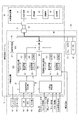
- FIG. 1 is an overall configuration diagram of a failure diagnosis system according to an embodiment.
- FIG. The time chart of the various count processing by an idle stop control apparatus.
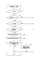
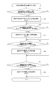
- FIG. 4 is a sub-flowchart of “the latest factor-by-factor prohibition count counting process” in FIG. 3.
- FIG. 1 shows the overall configuration of the failure diagnosis system 10.
- Failure diagnosis system 10 includes an idle stop control device 20 that is mounted on vehicle 90 and controls an idle stop of engine 91, and an external diagnosis device 30.
- the external diagnostic device 30 is connected to the idle stop control device 20 and exchanges information with the idle stop control device 20 to diagnose the vehicle 90.
- the idle stop control device 20 includes an idle stop condition establishment determination unit 21, an idle stop prohibition determination unit 22, a condition establishment number counter 230, a factor-by-factor prohibition number counter 250, a failure determination unit 27, an input / output unit 28, and the like.
- the idle stop condition establishment determination unit 21 is configured to shift information from a TCM (Transmission Control Module) 93, wheel pulses from an ESC (Electronic Stability Control, ie, skid prevention device) 94, stop master cylinder pressure information, and other information sources 95. Get each information from. Based on the acquired information, the idle stop condition establishment determination unit 21 determines that the vehicle stop condition is established as an “idle stop condition” that is a predetermined condition for stopping idling of the engine 91.
- TCM Transmission Control Module
- ESC Electronic Stability Control, ie, skid prevention device
- the idle stop prohibition determination unit 22 When the idle stop condition is satisfied, the idle stop prohibition determination unit 22 further generates one or more specific “idle stop prohibition factors” (hereinafter referred to as “prohibition factors”) that prohibit the execution of the idle stop. Then, it is determined that the idle stop prohibition condition is satisfied.
- specific prohibition factor include stop master cylinder pressure, engine hood opening, light drive, blower drive, and the like.
- the master cylinder pressure condition for stop is caused by insufficient pressure for the user to depress the brake pedal.
- the brake is not fully depressed by the user while the vehicle is stopped and the master cylinder pressure for stopping is less than a predetermined value, idle stop is not executed.
- This factor is considered to be mainly based on the user's daily usage of the car or user characteristics that should be called ⁇ . In this way, the prohibition factor based on the user characteristics is referred to as “user characteristic factor”.
- the engine hood opening condition occurs, for example, when you forget to close the hood after daily inspection. Also in this case, idle stop is not executed. It is considered that accidental factors unintended by the user, such as forgetting to close the hood, are not limited to any user and may occur in the same manner. In this way, a prohibition factor that is not based on user characteristics is referred to as a “non-user characteristic factor”. In addition, environmental factors such as weather also correspond to non-user characteristic factors.
- Light drive and blower drive are prohibited factors generated by prioritizing continuation of engine drive to ensure the supply of power for auxiliary equipment when driving auxiliary equipment such as various lights and air conditioner blowers while the vehicle is stopped. is there. It should be noted that factors such as light driving and blower driving cannot be generally discriminated whether they are user characteristic factors or non-user characteristic factors depending on conditions such as the vehicle usage region and season. For example, in an area where it is natural to cool while riding in a country with a tropical climate, the use of a blower while stopped is considered to be a non-user characteristic factor that does not depend on user characteristics. On the other hand, in regions with a warm climate that does not require air conditioning on a daily basis, the use of a blower while stopped is considered to be a user characteristic factor. Thus, the distinction between user characteristic factors and non-user characteristic factors is not absolute, and is appropriately determined according to the region, season, and the like.
- the idle stop prohibition determination unit 22 notifies the idle stop condition satisfaction determination unit 21 to prohibit the idle stop when the idle stop prohibition factor is further generated when the idle stop condition is satisfied. In this case, even when the vehicle is stopped and the idle stop condition is satisfied, the idle stop is not executed.
- the idle stop condition satisfaction determination unit 21 requests to stop the engine 91 and Execute. This contributes to fuel efficiency reduction and environmental protection.
- the idle stop condition establishment determining unit 21 drives the starter 92 to start the engine 91. Since such idle stop control is a well-known technique, detailed description is abbreviate
- the condition satisfaction number counter 230 counts “the number of times that the idle stop condition is satisfied”, which is “the number of times that the idle stop condition satisfaction determination unit 21 determines that the idle stop condition is satisfied”.
- the number of times the idle stop condition is satisfied is simply referred to as “the number of conditions satisfied”.
- the factor-based prohibition counter 250 counts “idle stop prohibition count” (hereinafter referred to as “prohibition count”), which is “the number of times the idle stop prohibition determination unit 22 determines that the idle stop prohibition condition is satisfied”. .
- the factor-by-factor prohibition count counter 250 of this embodiment counts the number of prohibitions by factor for a plurality of prohibition factors.
- the “prohibition count counter 250” will be referred to as appropriate wherever it is not necessarily “by factor”.
- condition establishment number counter 230 and the prohibition number counter 250 occupant authentication information indicating whether or not the occupant as a driver is the main user is input. When a user different from the main user gets on as a driver, the counting of various times is prohibited.
- the condition satisfaction number counter 230 and the prohibition number counter 250 are respectively the latest number counters 23 and 25 for counting the latest number of occurrences, and the past number counter 24 for counting the past number of occurrences before the start of counting the latest number of occurrences. , 26.
- the condition satisfaction number counter 230 includes nonvolatile memories 231 and 241 for storing and holding the count values of the latest number counter 23 and the past number counter 24, respectively.
- the factor-by-factor prohibited number counter 250 has nonvolatile memories 251 and 261 that store and hold the count values of the latest number counter 25 and the past number counter 26, respectively.
- the non-volatile memories 231, 241, 251, and 261 as “storage units” are composed of, for example, an EEPROM, and can store and hold the count values of the respective counters even when the vehicle 90 is powered off.
- the failure determination unit 27 has the same configuration as the conventional one, determines that a failure related to the idle stop control device has occurred, and stores a DTC (Diagnostic Trouble Code) corresponding to the failure content.
- the input / output unit 28 is connected to a network bus 40 as a communication path and can be accessed from the outside. In the present embodiment, it is possible to read and reset the number of established conditions and the number of prohibitions from the outside via the input / output unit 28. In other embodiments, it is sufficient that at least the number of prohibitions can be read or reset.
- the DTC stored by the failure determination unit 27 can also be read from the outside via the input / output unit 28.
- various input / output information related to the idle stop condition establishment determination unit 21 and the idle stop prohibition determination unit 22 is actually communicated with other control devices and the like via the input / output unit 28.
- illustration of those communication paths is omitted.
- the network bus 40 is an electronic network transmission path composed of a plurality of control devices mounted in the vehicle 90.
- the idle stop control device 20 is provided to be able to communicate with other control devices such as the brake ECU 41 and the AT-ECU (that is, automatic transmission ECU) 42 via the network bus 40.
- CAN is used as a network protocol.
- the idle stop control device 20 and a plurality of control devices in the vehicle 90 may be provided so as to communicate with each other via individual communication paths.
- the external diagnostic device 30 is connected to the idle stop control device 20 via a communication cable 52 or the like connected to the data link connector 51 of the vehicle 90, and exchanges information with the idle stop control device 20 to diagnose the vehicle 90. .
- wireless communication may be used instead of connection of the communication cable 52.
- the external diagnostic device 30 includes an input / output unit 31, an operation unit 32, a calculation unit 33, and a display unit 34.
- the input / output unit 31 inputs / outputs information to / from the vehicle 90. Further, information may be input / output to / from an external device other than the vehicle 90 (for example, an external server).
- the operation unit 32 includes a keyboard, a mouse, a touch pad, etc. (not shown).
- the calculation unit 33 executes various calculations related to the diagnosis of the vehicle 90. For example, the frequency for each factor is calculated based on the number of prohibitions for each factor.
- the display unit 34 displays an operation screen of the external diagnostic device 30 and a diagnostic result. The diagnosis result can be displayed not only as a numerical value but also as a graph.
- the external diagnostic device 30 is used by service personnel of an automobile dealer.
- the external diagnostic device 30 is not limited to a dedicated machine, and may be configured with a general-purpose notebook personal computer, a tablet computer, or a smartphone.
- the external diagnostic device 30 is not limited to a configuration as a single device, and may be configured from, for example, a personal computer as a main body and a slave unit (that is, a tester) as an interface with the vehicle 90.
- FIG. 2 shows time charts of (a) vehicle speed, (b) number of times the condition is satisfied, (c) number of idle stop non-executions, and (d) number of prohibition by factor in various count processing.
- the time axis represents a period from the past to the present through the latest.
- Various count processing is executed at the timing of transition from the time of stopping to the time of departure.
- the number of inhibitions by factor is counted for each inhibition factor, such as a stop master cylinder pressure condition, an engine hood opening condition, a light driving condition, and a blower driving condition.
- the condition satisfaction count and the factor-by-factor prohibition count are output as a result of “various count count processing” by the idle stop control device 20. Assuming that the idle stop condition is always satisfied when the vehicle is stopped, the number of satisfied conditions coincides with the number of stops, and increases once for each stop.
- the idle stop non-execution count is the number of times that the idle stop is not executed even though the idle stop condition is satisfied. Note that the idle stop non-execution count is only shown for reference, and may not be output as a result of the count process.
- the number of times the condition is satisfied and the number of prohibitions by factor are stored separately for the most recent number and the past number.
- the upper limit is restricted with respect to the most recent number of conditions established.
- the most recent condition establishment count reaches the upper limit
- the most recent condition establishment count and the latest factor-by-factor prohibition count are set to the past condition satisfaction count and the past factor-by-factor prohibition count, respectively.
- the most recent condition satisfaction count and the most recent factor-by-factor prohibition count are reset to zero.
- “past” and “most recent” on the time axis are distinguished from each other at the switching time tx when the most recent condition establishment count reaches the upper limit.
- S ⁇ b> 11 it is determined whether the user is currently on the vehicle 90 from the history of opening the door.
- “the user gets on” means that the user gets on the driver's seat as a driver, and basically does not mean that the user gets on the passenger seat or the rear seat.
- S ⁇ b> 12 it is determined whether or not the boarded user is the main user of the vehicle 90.
- the determination method of being a main user may be any method such as execution of a secret operation known only by the main user, password input, face image authentication, and the like.
- S13 it is determined whether or not the engine 91 has been started.
- S14 it is determined whether or not the stoppage determination has changed from “present” to “not present”, that is, whether or not the vehicle 90 has started to travel from a stopped state. If YES in all of S11 to S14, the process proceeds to S20. On the other hand, if any of S11 to S14 is NO, the process is terminated.
- the latest number counter 23 for the number of satisfied conditions counts the latest number of satisfied conditions determined by the idle stop condition satisfaction determining unit 21.
- the latest number counter 25 for the number of prohibitions by factor counts the latest number of prohibitions by factor determined by the idle stop prohibition determination unit 22.
- FIG. 4 is referred to for details of the “most recent factor-by-factor prohibition count processing” in S30. 4 exemplifies the determination of presence / absence of the determination by the idle stop prohibition determination unit 22 and the counting step by the latest count counter 25 for the prohibition factors of the four items. However, the same steps may be repeated for other prohibition factors, and the execution order is not limited. Further, in each determination step after S31, the history through the period of “stop determination is present” is evaluated retroactively from the present when the stop determination is changed from “present” to “none” in S14.
- S31 it is determined whether or not the master cylinder pressure for stoppage was not always determined during the “stop determination is present” period.
- S32 the latest “number of prohibitions due to the master cylinder pressure for stop” is counted.
- S33 it is determined whether or not the prohibition condition of “engine hood open determination is present” is satisfied even once during the period of “stop determination is present”. In the case of YES in S33, the most recent “number of prohibitions due to opening of the engine hood” is counted in S34.
- S35 it is determined whether or not the prohibition condition of “with light drive determination” is satisfied even once during the period of “with stop determination”. If YES in S35, the most recent "prohibition number by write drive” is counted in S36.
- S37 it is determined whether or not the prohibition condition “with blower drive determination” is satisfied even once during the period “with stop determination”. In the case of YES in S37, the most recent “prohibition number by blower drive” is counted in S38. When the counting for all the prohibition factor items is completed, the “most recent factor-specific prohibition count counting process” in S30 ends.
- S ⁇ b> 41 it is determined whether or not the most recent condition establishment count, that is, the count value of the latest count counter 23 for the condition establishment count is less than the upper limit value. If YES in S41, the process ends. On the other hand, when the most recent number of satisfied conditions reaches the upper limit value, NO is determined in S41, and the process proceeds to S42.
- various recent counts are set as past counts. In other words, the count value of the latest count counter 23 for the number of conditions satisfied is set in the past count counter 24, and the count value of the latest count counter 25 for the number of prohibition by factor is set in the past count counter 26. The various count processing routines are thus completed.
- the idle stop control device 20 does not execute the idle stop when the idle stop prohibition factor is generated even if the idle stop condition is satisfied.
- the idle stop prohibition factor is generated even if the idle stop condition is satisfied.
- users who have just purchased the vehicle 90 often do not grasp the idle stop prohibition factor. Therefore, the user cannot determine whether the non-execution of idle stop is due to normal control based on the prohibition factor or due to a vehicle failure, and makes an inquiry to the car dealer from anxiety. Many cases arise.
- the external diagnosis device 30 is connected to the idle stop control device 20 directly or via the electronic network of the vehicle 90 and is configured to be able to read at least the number of prohibitions. ing.
- the external diagnostic device 30 can read out the condition establishment count, idle stop non-execution count, and prohibition count by factor.
- Information on the number of established conditions, the number of idle stop non-executions, and the number of prohibited times by factor acquired by the input / output unit 31 of the external diagnostic device 30 is notified to the calculation unit 33 and the display unit 34.
- the calculation unit 33 calculates the cause-by-factor prohibition factor occurrence frequency based on the factor-by-factor prohibition count. Alternatively, the ratio of the idle stop non-execution count to the condition satisfaction count can be calculated.
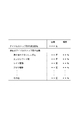
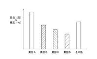
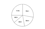
- the display unit 34 displays, for example, the condition establishment count, the factor-by-factor prohibition count, and the occurrence frequency in a table format as shown in FIG. Alternatively, for example, graphs may be displayed in order from the most frequent factors in the form of a bar graph or a pie chart shown in FIGS. 6A and 6B. Note that there may be only one type of specific prohibition factor that occurs during the diagnosis target period. The serviceman looks at this display and compares, for example, the number of times the condition is satisfied and the number of prohibitions for a plurality of factors, and says, “How often does this user cause idle stop non-execution? " As a result, the cause of idle stop non-execution can be diagnosed accurately and in a short time.
- steps S65 to S67 that are characteristic steps of the present embodiment.
- various count value information is read from the idle stop control device 20, and the number of forbidden factors and occurrence frequency are displayed on the screen.
- S66 the service person analyzes factors based on the displayed number of times and frequency information.
- the service person re-interrogates the user based on the analysis result. For example, if the number of prohibition times due to stop master cylinder pressure determination is large, check how much the user steps on the brake while the vehicle is stopped, and if it is not easy to step, inform that it is a prohibition factor . For example, when the number of prohibitions due to opening of the engine hood is large, an inquiry is made as to whether or not you forget to close the hood after daily inspection. In this way, based on the result of the re-interrogation, the service person specifies the cause of the idle stop failure in S68.
- Patent Document 1 Japanese Patent No. 5714132
- an external diagnostic device is connected to a vehicle, and a fault code written in each of a plurality of ECUs is read by the external diagnostic device.
- the operator needs to have the user reproduce the driving state that “the idle stop often does not work” in order to determine whether the idle stop is normally executed while driving the vehicle. , Interview takes time.
- the burden on the user is increased because the driving state is reproduced by the user traveling together.
- the idle stop control device 20 and the failure diagnosis system 10 of the present embodiment have the following operational effects.
- the idle stop control device 20 includes a prohibition number counter 250 that counts the number of times that execution of idle stop is prohibited due to occurrence of one or more specific prohibition factors.
- the count value of occurrence of a specific prohibition factor can be used as diagnostic information. Therefore, in the diagnosis of “the factor that the idle stop is not executed even though the idle stop condition is satisfied”, by using the information on the number of prohibition factor occurrences, it becomes unnecessary to reproduce the driving state by the user, and the diagnosis time is reduced. It can be shortened. In addition, it is possible to appropriately deal with problems that cannot be solved by the conventional DTC.
- the prohibition count counter 250 of the present embodiment counts the number of prohibitions determined to have generated any of the prohibition factors among a plurality of specific prohibition factors. Is. As a result, the cause of idle stop non-execution can be widely diagnosed for each prohibited factor.
- the count value of the prohibition count by the factor-specific prohibition count counter 250 is stored and held in the nonvolatile memories 251 and 261. If the relationship between the operating factor and the idle stop non-execution state is stored in association with the time axis, the storage capacity of the memory increases. On the other hand, the storage capacity of the memory can be reduced by storing the number of prohibitions for each factor. In addition, since a nonvolatile memory is used as the storage unit, the count value of the number of prohibitions can be stored and held even when the vehicle 90 is powered off.
- the idle stop control device 20 further includes a condition satisfaction number counter 230 that counts the number of times the condition is determined to have been determined that the idle stop condition is satisfied. Thereby, it is possible to make a determination by comparing the number of times the condition is satisfied and the number of prohibitions.
- the condition satisfaction number counter 230 also has the nonvolatile memories 231 and 241 that can store and hold the condition satisfaction number in the same manner as the factor-by-factor prohibition number counter 250, so that the number of condition satisfaction times when the vehicle 90 is powered off. The count value can be stored and held.
- the condition satisfaction count counter 230 and the factor-based prohibition count counter 250 count the latest occurrence counts 23 and 25 for counting the most recent occurrence count, and the past occurrence count before the start of the latest occurrence count count, respectively.
- Past number counters 24 and 26 to be included.
- the factor-by-factor prohibition counter 250 prohibits counting the factor-by-factor prohibition count when it is detected that a user different from the main user of the vehicle 90 has boarded.
- the condition satisfaction number counter 230 similarly compares the number of times the condition is satisfied and the number of prohibitions by prohibiting the count of the condition satisfaction number. The reliability of data in judgment can be improved.
- the prohibition factors include user characteristic factors that are factors based on user characteristics, such as a stop master cylinder pressure condition. That is, each prohibition factor based on the user's daily usage of the car and the trap is grasped as one of the factor groups of idle stop execution.
- the prohibited factors include non-user characteristic factors that are factors that are not based on user characteristics, such as engine hood opening conditions. That is, each forbidden factor that is generated without the intention of the user is grasped as one of the factor groups of idle stop non-execution.
- the idle stop control device 20 includes an input / output unit 28 that can be accessed from the outside so as to read or reset at least the number of prohibitions. Thereby, the service person can read and diagnose the number of prohibitions while the idle stop control device 20 is mounted on the vehicle 90, and can perform initialization after completion of the diagnosis. Therefore, the operability is improved and the diagnosis time is shortened. It is also useful for debugging during development.
- the input / output unit 28 of the idle stop control device 20 is another one via an individual communication path or an electronic network 40 constructed by a plurality of control devices mounted in the vehicle 90. It is provided to be able to communicate with the control devices 41 and 42 described above. Thereby, the internal information of the idle stop control device 20 can be read and written from other control devices of the vehicle 90, and diagnosis can be performed without using the dedicated external diagnostic device 30. In addition, there is no need to set a diagnostic-only communication means.
- the failure diagnosis system 10 includes an idle stop control device 20 and an external diagnosis device 30 that is connected to the idle stop control device 20 and exchanges information with the idle stop control device 20 to diagnose the vehicle 90. , "Factor that idle stop is not executed when idle stop condition is satisfied" is diagnosed.
- the external diagnostic device 30 is connected to the idle stop control device 20 directly or via the network of the vehicle 90 and can read at least the number of prohibitions. Thereby, failure diagnosis can be executed while the idle stop control device 20 is mounted on the vehicle. Moreover, since the cause of idle stop non-execution can be analyzed based on the read prohibition count, the diagnosis time can be shortened.
- the display unit 34 of the external diagnostic device 30 displays information including the number of prohibitions read from the idle stop control device 20 on the screen. Further, in the present embodiment in which the prohibition count counter 250 of the idle stop control device 20 counts the prohibition count for each factor with respect to a plurality of prohibition factors, the calculation unit 33 determines the frequency of prohibition factor generation for each factor based on the prohibition count for each factor. Is calculated. And the display part 34 displays the prohibition factor generation frequency according to the factor which the calculating part 33 computed with a numerical value or a graph. Thereby, the cause analysis of idle stop non-execution by the service person becomes easy, and the diagnosis time can be shortened.
- the calculation unit 33 calculates the ratio of the factor-by-factor prohibition number to the condition satisfaction number, and the display unit 34 displays the ratio. It is also possible. As a result, the service person can analyze the cause of idle stop non-execution based on the comprehensive information of the number of times the condition is satisfied and the number of prohibitions by factor. Therefore, a more accurate diagnosis can be performed in a short time.
- the idle stop control device may not include the condition satisfaction number counter, and may count only the number of prohibitions by the prohibition number counter. By minimizing the information used for diagnosis, it is possible to reduce the burden on the service person and the calculation load on the apparatus.
- the prohibition count counter is not limited to counting the number of prohibitions for each factor for a plurality of prohibition factors.
- the prohibition counter may count only the number of occurrences of one specific prohibition factor, and the service person may grasp the number of times. Thereby, the diagnosis specialized to one specific factor can be implemented more rapidly.
- the prohibition count counter may count the number of idle stop non-executions, which is the logical sum of the prohibition factors, as the prohibition count for a plurality of prohibition factors. In this case, the service person can grasp how often idle stop non-execution occurs, for example, by comparing the number of times of prohibition with the number of times the condition is satisfied.
- condition satisfaction number counter and the prohibition number counter may not be provided with the latest number counter and the past number counter separately, and the counter processing from the past to the latest may be performed with one counter. Alternatively, a plurality of past number counters may be provided, for example, every predetermined period.
- D The configuration related to information input / output of the idle stop control device 20 in the vehicle 90, the configuration related to the connection between the vehicle 90 and the external diagnostic device 30, the display configuration of the external diagnostic device 30, etc. are not limited to those described in each figure. Instead, any known technique may be combined.
- the specific idle stop prohibition factors are not limited to those exemplified in the above embodiment, and any prohibition factors may be applied depending on vehicle performance, use area, season, and the like.
- the idle stop control device of the present embodiment includes an idle stop condition establishment determination unit (21), an idle stop prohibition determination unit (22), and a prohibition count counter (250).
- the idle stop condition establishment determining unit determines that an idle stop condition that is a predetermined condition for stopping idling of the engine (91) of the vehicle (90) is established.
- the idle stop prohibition determination unit further determines that the idle stop prohibition condition is satisfied by occurrence of one or more specific prohibition factors that prohibit the execution of the idle stop. To do.
- the prohibition count counter counts “prohibition count” which is “the number of times the idle stop prohibition determination unit determines that the idle stop prohibition condition is satisfied”.
- the prohibition count counter may count only the number of occurrences of one specific prohibition factor, or may count only the idle stop non-execution count that is a logical sum of a plurality of prohibition factors. However, preferably, the prohibition count counter counts the prohibition count for each factor for a plurality of prohibition factors. As a result, the cause of idle stop non-execution can be widely diagnosed for each prohibited factor.
- the idle stop control device of the present invention includes a condition establishment number counter (230) that counts “condition establishment number” that is “the number of times that the idle stop condition establishment determination unit determines that the idle stop condition is established”. May be further provided. Thereby, it is possible to make a determination by comparing the number of times the condition is satisfied and the number of prohibitions.
- the failure diagnosis system of the present embodiment includes the above-described idle stop control device and an external diagnosis device (30) that is connected to the idle stop control device and exchanges information with the idle stop control device to diagnose the vehicle.
- the cause of the non-execution of the idle stop when the idle stop condition is satisfied is diagnosed.
- this failure diagnosis system it is possible to analyze the cause of the idle stop not being executed using the information on the number of occurrences of the specific prohibition factor, so that the diagnosis time can be shortened.
- this invention is not limited to the said embodiment at all, In the range which does not deviate from the meaning of invention, it can implement with a various form.
Landscapes
- Engineering & Computer Science (AREA)
- Chemical & Material Sciences (AREA)
- Combustion & Propulsion (AREA)
- Mechanical Engineering (AREA)
- General Engineering & Computer Science (AREA)
- Control Of Vehicle Engines Or Engines For Specific Uses (AREA)
- Combined Controls Of Internal Combustion Engines (AREA)
Abstract
アイドルストップ制御装置は、車両のエンジンのアイドリングを停止させる所定の条件であるアイドルストップ条件が成立していることを判定するアイドルストップ条件成立判定部と、前記アイドルストップ条件が成立しているとき、更に、アイドルストップの実行を禁止する一つ以上の特定の禁止要因の発生により、アイドルストップ禁止条件が成立していることを判定するアイドルストップ禁止判定部と、前記アイドルストップ禁止判定部により前記アイドルストップ禁止条件が成立していると判定された回数である禁止回数をカウントする禁止回数カウンタと、を備える。
Description
本発明は、車両のエンジンのアイドルストップを制御するアイドルストップ制御装置、及び、それを含む故障診断システムに関する。
従来、燃費低減や環境保護に貢献するためアイドルストップを実行する車両において、アイドルストップ条件が成立していても、更にアイドルストップ禁止条件が成立する場合には、アイドルストップを不実行とする技術が知られている。しかし、ユーザは、アイドルストップの不実行が禁止要因に基づく正常なものなのか、或いは、車両の故障によるものなのかを判断することができず、自動車販売店への問合せが多発する傾向にあった。
そのような背景に基づき特許文献1に開示された車両診断システムは、車両内の複数の電子制御装置と外部診断装置との間で通信を行い、車両の故障診断を行う。外部診断装置には、複数の電子制御装置のいずれかに登録されたアイドルストップを行うための複数のアイドルストップ条件が登録されている。そして、外部診断装置を車両に接続して車両を運転した時の停車時に、アイドルストップが不実行の場合において満たされないアイドルストップ条件を所定の表示部に表示する。
特許文献1の車両診断システムでは、作業者は、車両を運転している状態でアイドルストップが正常に実行されているかを判定するために、「アイドルストップが作動しないことが多い」という運転状態をユーザに再現してもらう必要があり、問診に時間を要する。また、ユーザに同乗してもらって運転状態を再現するため、ユーザへの負担が大きくなるという問題がある。
これらの課題を解決する手段として、必要な情報を予めDTC(すなわち故障コード)や、それに関連付けた情報により電子制御装置に記憶させる方法が一般に知られている。しかし、アイドルストップしないという問合せは、車両は正常動作しているにもかかわらず、ユーザの日常的な車の使い方においてアイドルストップを禁止する条件が存在しており、しかもユーザがそれを認識できていない場合に生じることが多い。そのため、従来のDTCだけでは解決できないという問題がある。
一実施形態は、アイドルストップの不実行についての診断を適確且つ短時間に実施可能とするアイドルストップ制御装置、及び、それを含む故障診断システムを提供する。
実施形態のアイドルストップ制御装置は、車両のエンジンのアイドリングを停止させる所定の条件であるアイドルストップ条件が成立していることを判定するアイドルストップ条件成立判定部と、前記アイドルストップ条件が成立しているとき、更に、アイドルストップの実行を禁止する一つ以上の特定の禁止要因の発生により、アイドルストップ禁止条件が成立していることを判定するアイドルストップ禁止判定部と、前記アイドルストップ禁止判定部により前記アイドルストップ禁止条件が成立していると判定された回数である禁止回数をカウントする禁止回数カウンタと、を備える。
(一実施形態)
以下、本発明のアイドルストップ制御装置、及び故障診断システムの一実施形態を図面に基づいて説明する。図中、「アイドルストップ」を「IS」と記す。
図1に故障診断システム10の全体構成を示す。故障診断システム10は、車両90に搭載されエンジン91のアイドルストップを制御するアイドルストップ制御装置20と、外部診断装置30とを含む。外部診断装置30は、アイドルストップ制御装置20に接続され、アイドルストップ制御装置20と情報を交換して車両90の診断を行う。
以下、本発明のアイドルストップ制御装置、及び故障診断システムの一実施形態を図面に基づいて説明する。図中、「アイドルストップ」を「IS」と記す。
図1に故障診断システム10の全体構成を示す。故障診断システム10は、車両90に搭載されエンジン91のアイドルストップを制御するアイドルストップ制御装置20と、外部診断装置30とを含む。外部診断装置30は、アイドルストップ制御装置20に接続され、アイドルストップ制御装置20と情報を交換して車両90の診断を行う。
アイドルストップ制御装置20は、アイドルストップ条件成立判定部21、アイドルストップ禁止判定部22、条件成立回数カウンタ230、要因別禁止回数カウンタ250、故障判定部27、入出力部28等を備える。
アイドルストップ条件成立判定部21は、TCM(Transmission Control Module)93からのシフト情報、ESC(Electronic Stability Control、すなわち横滑り防止装置)94からの車輪パルス、停止用マスタシリンダ圧情報、その他の情報源95からの各情報を取得する。アイドルストップ条件成立判定部21は、取得した情報に基づき、エンジン91のアイドリングを停止させる所定の条件である「アイドルストップ条件」として、車両停止条件が成立していることを判定する。
アイドルストップ条件成立判定部21は、TCM(Transmission Control Module)93からのシフト情報、ESC(Electronic Stability Control、すなわち横滑り防止装置)94からの車輪パルス、停止用マスタシリンダ圧情報、その他の情報源95からの各情報を取得する。アイドルストップ条件成立判定部21は、取得した情報に基づき、エンジン91のアイドリングを停止させる所定の条件である「アイドルストップ条件」として、車両停止条件が成立していることを判定する。
アイドルストップ禁止判定部22は、アイドルストップ条件が成立しているとき、更に、アイドルストップの実行を禁止する一つ以上の特定の「アイドルストップ禁止要因」(以下、「禁止要因」)の発生により、アイドルストップ禁止条件が成立していることを判定する。特定の禁止要因としては、例えば、停止用マスタシリンダ圧、エンジンフード開、ライト駆動、ブロワ駆動等が挙げられる。
停止用マスタシリンダ圧条件は、ユーザがブレーキペダルを踏み込む圧力の不足により発生する。停車中にユーザによるブレーキの踏み込みが甘く、停止用マスタシリンダ圧が所定値未満の場合、アイドルストップは実行されない。この要因は、主としてユーザの日常的な車の使い方、或いは癖とも言うべきユーザ特性に基づくものであると考えられる。このように、ユーザの特性に基づく禁止要因を「ユーザ特性要因」という。
エンジンフード開条件は、例えば日常点検後のフードの閉め忘れにより発生する。この場合にもアイドルストップは実行されない。フードの閉め忘れ等のユーザの意図しない偶発的要因は、どのユーザに限らず、同様に発生する可能性があると考えられる。このように、ユーザの特性に基づかない禁止要因を「非ユーザ特性要因」という。その他、天候等の環境的要因も非ユーザ特性要因に該当する。
ライト駆動及びブロワ駆動は、停車中に各種ライトやエアコン用ブロワ等の補機を駆動する場合、補機用電力の供給を確保するためにエンジン駆動の継続を優先することにより発生する禁止要因である。
なお、ライト駆動及びブロワ駆動等の要因は、車両の使用地域や季節等の条件により、ユーザ特性要因であるか、非ユーザ特性要因であるかを一概に区別することはできない。例えば、熱帯気候の国で乗車中に冷房をかけることが当然の地域では、停車中のブロワの使用は、ユーザ特性によらない非ユーザ特性要因であると考えられる。一方、日常的にエアコンを必要としない温暖な気候の地域では、停車中のブロワの使用は、ユーザ特性要因に該当するとも考えられる。このように、ユーザ特性要因であるか、非ユーザ特性要因であるかの区別は絶対的なものではなく、地域や季節等に応じて適宜判断される。
なお、ライト駆動及びブロワ駆動等の要因は、車両の使用地域や季節等の条件により、ユーザ特性要因であるか、非ユーザ特性要因であるかを一概に区別することはできない。例えば、熱帯気候の国で乗車中に冷房をかけることが当然の地域では、停車中のブロワの使用は、ユーザ特性によらない非ユーザ特性要因であると考えられる。一方、日常的にエアコンを必要としない温暖な気候の地域では、停車中のブロワの使用は、ユーザ特性要因に該当するとも考えられる。このように、ユーザ特性要因であるか、非ユーザ特性要因であるかの区別は絶対的なものではなく、地域や季節等に応じて適宜判断される。
アイドルストップ禁止判定部22は、アイドルストップ条件の成立時に更に上記のようなアイドルストップ禁止要因が発生しているとき、アイドルストップ条件成立判定部21に対し、アイドルストップを禁止するように通知する。この場合、停車中でアイドルストップ条件が成立していても、アイドルストップは実行されない。
一方、アイドルストップ条件が成立しており、且つ、アイドルストップ禁止判定部22からアイドルストップ禁止の通知がされないとき、アイドルストップ条件成立判定部21は、エンジン91を停止するように要求し、アイドルストップを実行する。これにより、燃費低減や環境保護に貢献する。
また、アイドルストップによるエンジン91の停止後、アイドルストップ条件が解消したとき、アイドルストップ条件成立判定部21は、スタータ92を駆動してエンジン91を始動させる。
このようなアイドルストップ制御は周知技術であるため、詳細な説明を省略する。
また、アイドルストップによるエンジン91の停止後、アイドルストップ条件が解消したとき、アイドルストップ条件成立判定部21は、スタータ92を駆動してエンジン91を始動させる。
このようなアイドルストップ制御は周知技術であるため、詳細な説明を省略する。
次に、本実施形態の特徴構成である各カウンタの構成を説明する。
条件成立回数カウンタ230は、「アイドルストップ条件成立判定部21によりアイドルストップ条件が成立していると判定された回数」である「アイドルストップ条件成立回数」をカウントする。以下、「アイドルストップ条件成立回数」を単に「条件成立回数」という。
条件成立回数カウンタ230は、「アイドルストップ条件成立判定部21によりアイドルストップ条件が成立していると判定された回数」である「アイドルストップ条件成立回数」をカウントする。以下、「アイドルストップ条件成立回数」を単に「条件成立回数」という。
要因別禁止回数カウンタ250は、「アイドルストップ禁止判定部22によりアイドルストップ禁止条件が成立していると判定された回数」である「アイドルストップ禁止回数」(以下、「禁止回数」)をカウントする。特に本実施形態の要因別禁止回数カウンタ250は、複数の禁止要因について要因別の禁止回数をカウントする。
以下の要因別禁止回数カウンタ250に関する説明において、必ずしも「要因別」であることが前提とならない箇所では、適宜、「禁止回数カウンタ250」と記す。
以下の要因別禁止回数カウンタ250に関する説明において、必ずしも「要因別」であることが前提とならない箇所では、適宜、「禁止回数カウンタ250」と記す。
条件成立回数カウンタ230及び禁止回数カウンタ250には、運転手としての乗員がメインユーザであるか否かの乗員認証情報が入力される。そして、メインユーザとは異なるユーザが運転手として乗車した場合、各種回数のカウントを禁止する。
条件成立回数カウンタ230及び禁止回数カウンタ250は、それぞれ、直近の発生回数をカウントする直近回数カウンタ23、25、及び、直近の発生回数のカウント開始以前の過去の発生回数をカウントする過去回数カウンタ24、26を含む。
条件成立回数カウンタ230及び禁止回数カウンタ250は、それぞれ、直近の発生回数をカウントする直近回数カウンタ23、25、及び、直近の発生回数のカウント開始以前の過去の発生回数をカウントする過去回数カウンタ24、26を含む。
また、条件成立回数カウンタ230は、直近回数カウンタ23及び過去回数カウンタ24のカウント値をそれぞれ記憶保持する不揮発メモリ231、241を有する。同様に、要因別禁止回数カウンタ250は、直近回数カウンタ25及び過去回数カウンタ26のカウント値をそれぞれ記憶保持する不揮発メモリ251、261を有する。「記憶部」としての不揮発メモリ231、241、251、261は、例えばEEPROMで構成され、車両90の電源が切断された場合でも、各カウンタのカウント値を記憶保持可能である。
故障判定部27は、従来と同様の構成であり、アイドルストップ制御装置に関する故障が発生したことを判定し、故障内容に応じたDTC(Diagnostic Trouble Code、すなわち故障コード)を記憶する。
入出力部28は、通信経路としてのネットワークバス40に接続されており、外部からのアクセスが可能である。本実施形態では、入出力部28を介して、外部からの条件成立回数及び禁止回数の読み出しやリセットが可能である。なお、他の実施形態では、少なくとも禁止回数の読み出しやリセットが可能であればよい。
入出力部28は、通信経路としてのネットワークバス40に接続されており、外部からのアクセスが可能である。本実施形態では、入出力部28を介して、外部からの条件成立回数及び禁止回数の読み出しやリセットが可能である。なお、他の実施形態では、少なくとも禁止回数の読み出しやリセットが可能であればよい。
また、故障判定部27が記憶したDTCについても、入出力部28を介して外部からの読み出しが可能である。
なお、アイドルストップ条件成立判定部21やアイドルストップ禁止判定部22に係る各種入出力情報も、実際には入出力部28を介して他の制御装置等との間で通信される。ただし、図1では煩雑になることを避けるため、それらの通信経路の図示を省略する。
なお、アイドルストップ条件成立判定部21やアイドルストップ禁止判定部22に係る各種入出力情報も、実際には入出力部28を介して他の制御装置等との間で通信される。ただし、図1では煩雑になることを避けるため、それらの通信経路の図示を省略する。
ネットワークバス40は、車両90内に搭載された複数の制御装置で構成される電子的ネットワークの伝送路である。アイドルストップ制御装置20は、ネットワークバス40を経由して、ブレーキECU41やAT-ECU(すなわち自動変速機ECU)42等の他の制御装置と通信可能に設けられている。ネットワークプロトコルとして、代表的にはCANが使用される。なお他の実施形態では、アイドルストップ制御装置20と車両90内の複数の制御装置とが個別の通信経路を経由して通信可能に設けられてもよい。
外部診断装置30は、車両90のデータリンクコネクタ51に接続された通信ケーブル52等を介してアイドルストップ制御装置20に接続され、アイドルストップ制御装置20と情報を交換して車両90の診断を行う。なお、通信ケーブル52の接続に代えて無線通信を用いてもよい。
外部診断装置30は、入出力部31、操作部32、演算部33、表示部34を備える。
入出力部31は、車両90との間で情報を入出力する。また、車両90以外の外部機器(例えば外部サーバ)との間で情報を入出力してもよい。
操作部32は、図示しないキーボードやマウス、タッチパッド等からなる。
演算部33は、車両90の診断に関する各種演算を実行する。例えば、要因別禁止回数に基づいて要因別頻度を演算する。
表示部34は、外部診断装置30の操作画面や診断結果を表示する。診断結果は、数値表示のみでなくグラフ等でも表示可能である。
入出力部31は、車両90との間で情報を入出力する。また、車両90以外の外部機器(例えば外部サーバ)との間で情報を入出力してもよい。
操作部32は、図示しないキーボードやマウス、タッチパッド等からなる。
演算部33は、車両90の診断に関する各種演算を実行する。例えば、要因別禁止回数に基づいて要因別頻度を演算する。
表示部34は、外部診断装置30の操作画面や診断結果を表示する。診断結果は、数値表示のみでなくグラフ等でも表示可能である。
外部診断装置30は、自動車販売店のサービスマン等により使用される。外部診断装置30は、専用機に限らず、汎用ノート型パーソナルコンピュータ、タブレット型コンピュータ又はスマートフォンで構成されてもよい。また、外部診断装置30は、単一の装置としての構成に限らず、例えば、本体としてのパーソナルコンピュータと、車両90とのインタフェースとしての子機(すなわちテスタ)とから構成されてもよい。
[アイドルストップ制御装置の各種カウント処理]
次に、条件成立回数カウンタ230及び要因別禁止回数カウンタ250による各種回数カウント処理について、図2~図4を参照して説明する。
図2に、各種回数カウント処理における(a)車速、(b)条件成立回数、(c)アイドルストップ不実行回数、(d)要因別禁止回数のタイムチャートを示す。時間軸は、過去から直近を経て現在までの期間を表す。
次に、条件成立回数カウンタ230及び要因別禁止回数カウンタ250による各種回数カウント処理について、図2~図4を参照して説明する。
図2に、各種回数カウント処理における(a)車速、(b)条件成立回数、(c)アイドルストップ不実行回数、(d)要因別禁止回数のタイムチャートを示す。時間軸は、過去から直近を経て現在までの期間を表す。
車速については、車速=0である停車時、発進時、定常走行時、及び減速時の区別のみを表し、定常走行時における車速は一定として示す。停車時から発進時に移行するタイミングで各種回数カウント処理が実行される。
要因別禁止回数は、停止用マスタシリンダ圧条件、エンジンフード開条件、ライト駆動条件、ブロワ駆動条件等の禁止要因別にカウントされる。
要因別禁止回数は、停止用マスタシリンダ圧条件、エンジンフード開条件、ライト駆動条件、ブロワ駆動条件等の禁止要因別にカウントされる。
条件成立回数及び要因別禁止回数は、アイドルストップ制御装置20による「各種回数カウント処理」の結果として出力される。停車時には必ずアイドルストップ条件が成立するという前提では、条件成立回数は、停車回数に一致し、停車毎に一回ずつ増加する。
アイドルストップ不実行回数は、アイドルストップ条件が成立したにもかかわらずアイドルストップが実行されなかった回数である。なお、アイドルストップ不実行回数は参照のために図示するのみであり、カウント処理の結果として出力されなくてもよい。
アイドルストップ不実行回数は、アイドルストップ条件が成立したにもかかわらずアイドルストップが実行されなかった回数である。なお、アイドルストップ不実行回数は参照のために図示するのみであり、カウント処理の結果として出力されなくてもよい。
条件成立回数及び要因別禁止回数は、それぞれ、直近回数と過去回数とに分けて記憶される。また、直近の条件成立回数に対して上限値が制限されている。直近の条件成立回数が上限値に達すると、直近の条件成立回数及び直近の要因別禁止回数が、それぞれ、過去の条件成立回数及び過去の要因別禁止回数に設定される。それと共に、直近の条件成立回数及び直近の要因別禁止回数は0にリセットされる。言い換えれば、直近の条件成立回数が上限値に達した切替時txを境として、時間軸の「過去」と「直近」とが区別される。
続いて、各種回数カウント処理のルーチンについて、図3及び図4のフローチャートを参照して説明する。フローチャートの説明で記号「S」はステップを意味する。S11~S14は、必ずしもアイドルストップ制御装置20自体が直接判断することを要せず、他の制御装置による判断結果等を取得してもよい。
S11では、ドアが開いた履歴から、現在ユーザが車両90に乗車しているか否か判断する。ここで、「ユーザが乗車する」とは、ユーザが運転者として運転席に乗車することを意味し、基本的に助手席や後部座席に乗車することを意味しない。
S12では、乗車したユーザが車両90のメインユーザであるか否か判断する。メインユーザであることの判断方法は、メインユーザのみが知っている秘密操作の実行、パスワード入力、顔の画像認証等、どのような方法であってもよい。
S12では、乗車したユーザが車両90のメインユーザであるか否か判断する。メインユーザであることの判断方法は、メインユーザのみが知っている秘密操作の実行、パスワード入力、顔の画像認証等、どのような方法であってもよい。
S13では、エンジン91が始動しているか否か判断する。
S14では、停車判定が「あり」から「なし」に変化したか、すなわち車両90が停止状態から走行し始めたか否か判断する。
S11~S14の全てでYESの場合、S20に移行する。一方、S11~S14のいずれかでNOの場合、処理を終了する。
S14では、停車判定が「あり」から「なし」に変化したか、すなわち車両90が停止状態から走行し始めたか否か判断する。
S11~S14の全てでYESの場合、S20に移行する。一方、S11~S14のいずれかでNOの場合、処理を終了する。
S20では、条件成立回数についての直近回数カウンタ23は、アイドルストップ条件成立判定部21により判定された直近の条件成立回数をカウントする。
S30では、要因別禁止回数についての直近回数カウンタ25は、アイドルストップ禁止判定部22により判定された直近の要因別禁止回数をカウントする。
S30では、要因別禁止回数についての直近回数カウンタ25は、アイドルストップ禁止判定部22により判定された直近の要因別禁止回数をカウントする。
S30の「直近の要因別禁止回数カウント処理」の詳細について図4を参照する。
図4では、4項目の禁止要因について、アイドルストップ禁止判定部22による判定有無の判断、及び、直近回数カウンタ25によるカウントのステップを例示する。ただし、他の禁止要因についても同様のステップを繰り返してもよく、その実行順序は問わない。
また、S31以下の各判断ステップは、S14で、停車判定が「あり」から「なし」に変化した現在から遡って、「停止判定あり」の期間を通じての履歴を評価する。禁止要因の特性により、「特定の禁止要因の発生によりアイドルストップ禁止条件が常時成立した場合」、又は、「特定の禁止要因の発生によりアイドルストップ禁止条件が一度でも成立した場合」のいずれかの場合に要因別禁止回数がカウントされる。
図4では、4項目の禁止要因について、アイドルストップ禁止判定部22による判定有無の判断、及び、直近回数カウンタ25によるカウントのステップを例示する。ただし、他の禁止要因についても同様のステップを繰り返してもよく、その実行順序は問わない。
また、S31以下の各判断ステップは、S14で、停車判定が「あり」から「なし」に変化した現在から遡って、「停止判定あり」の期間を通じての履歴を評価する。禁止要因の特性により、「特定の禁止要因の発生によりアイドルストップ禁止条件が常時成立した場合」、又は、「特定の禁止要因の発生によりアイドルストップ禁止条件が一度でも成立した場合」のいずれかの場合に要因別禁止回数がカウントされる。
S31では、「停止判定あり」の期間に、常時、停止用マスタシリンダ圧の判定がなかったか否か判断する。S31でYESの場合、S32で、直近の「停止用マスタシリンダ圧による禁止回数」がカウントされる。
S33では、「停止判定あり」の期間に、「エンジンフード開判定あり」の禁止条件が一度でも成立したか否か判断する。S33でYESの場合、S34で、直近の「エンジンフード開による禁止回数」がカウントされる。
S33では、「停止判定あり」の期間に、「エンジンフード開判定あり」の禁止条件が一度でも成立したか否か判断する。S33でYESの場合、S34で、直近の「エンジンフード開による禁止回数」がカウントされる。
S35では、「停止判定あり」の期間に、「ライト駆動判定あり」の禁止条件が一度でも成立したか否か判断する。S35でYESの場合、S36で、直近の「ライト駆動による禁止回数」がカウントされる。
S37では、「停止判定あり」の期間に、「ブロワ駆動判定あり」の禁止条件が一度でも成立したか否か判断する。S37でYESの場合、S38で、直近の「ブロワ駆動による禁止回数」がカウントされる。
全ての禁止要因項目についてのカウントが完了すると、S30の「直近の要因別禁止回数カウント処理」は終了する。
S37では、「停止判定あり」の期間に、「ブロワ駆動判定あり」の禁止条件が一度でも成立したか否か判断する。S37でYESの場合、S38で、直近の「ブロワ駆動による禁止回数」がカウントされる。
全ての禁止要因項目についてのカウントが完了すると、S30の「直近の要因別禁止回数カウント処理」は終了する。
図3に戻り、S41では、直近の条件成立回数、すなわち、条件成立回数についての直近回数カウンタ23のカウント値が上限値未満であるか否か判断する。S41でYESの場合、処理を終了する。一方、直近の条件成立回数が上限値に達したとき、S41でNOと判断され、S42に移行する。
S42では、各種直近回数を過去回数に設定する。すなわち、条件成立回数についての直近回数カウンタ23のカウント値を過去回数カウンタ24に設定し、要因別禁止回数についての直近回数カウンタ25のカウント値を過去回数カウンタ26に設定する。
以上で各種カウント処理のルーチンを終了する。
S42では、各種直近回数を過去回数に設定する。すなわち、条件成立回数についての直近回数カウンタ23のカウント値を過去回数カウンタ24に設定し、要因別禁止回数についての直近回数カウンタ25のカウント値を過去回数カウンタ26に設定する。
以上で各種カウント処理のルーチンを終了する。
[アイドルストップ不実行についての故障診断]
次に、本実施形態の故障診断システム10を用いたアイドルストップ不実行についての故障診断について、図5~図7を参照して説明する。
以上のようにアイドルストップ制御装置20は、アイドルストップ条件が成立していても更にアイドルストップ禁止要因が発生しているとき、アイドルストップを実行しない。しかし、特に車両90を購入して間もないユーザは、アイドルストップ禁止要因を把握していない場合が多い。そのため、ユーザは、アイドルストップの不実行が禁止要因に基づく正常な制御によるものなのか、或いは車両の故障によるものであるのかを判断することができず、不安感から自動車販売店へ問合せをする場合が多く生じる。
次に、本実施形態の故障診断システム10を用いたアイドルストップ不実行についての故障診断について、図5~図7を参照して説明する。
以上のようにアイドルストップ制御装置20は、アイドルストップ条件が成立していても更にアイドルストップ禁止要因が発生しているとき、アイドルストップを実行しない。しかし、特に車両90を購入して間もないユーザは、アイドルストップ禁止要因を把握していない場合が多い。そのため、ユーザは、アイドルストップの不実行が禁止要因に基づく正常な制御によるものなのか、或いは車両の故障によるものであるのかを判断することができず、不安感から自動車販売店へ問合せをする場合が多く生じる。
そのような問合せに対し、自動車販売店のサービスマンは、アイドルストップの不実行要因を適確且つ短時間に実行することが求められる。そこで、本実施形態の故障診断システム10では、外部診断装置30は、直接に、又は、車両90の電子的ネットワークを介してアイドルストップ制御装置20に接続され、少なくとも禁止回数を読み出し可能に構成されている。
図5、図6A、図6Bに示す例では、外部診断装置30は、条件成立回数、アイドルストップ不実行回数、及び要因別の禁止回数を読み出し可能であることを想定する。外部診断装置30の入出力部31が取得した条件成立回数、アイドルストップ不実行回数、及び要因別禁止回数の情報は、演算部33及び表示部34に通知される。演算部33は、要因別禁止回数に基づき、要因別の禁止要因発生頻度を演算する。或いは、条件成立回数に対するアイドルストップ不実行回数の比率を演算したりすることもできる。
表示部34は、例えば図5に示すような表形式で、条件成立回数、要因別禁止回数及び発生頻度を表示する。或いは、図6A、図6Bに示す棒グラフや円グラフ等の形式で、例えば頻度の高い要因から順にグラフ表示してもよい。なお、診断対象期間中に発生した特定の禁止要因が一種類のみであるという場合もあり得る。
サービスマンは、この表示を見て、例えば条件成立回数と複数の要因別の禁止回数とを比較し、「このユーザではどのような要因によりどの程度の頻度でアイドルストップの不実行が起きているか」を把握する。それにより、アイドルストップ不実行の要因の診断を適確且つ短時間に実施することができる。
サービスマンは、この表示を見て、例えば条件成立回数と複数の要因別の禁止回数とを比較し、「このユーザではどのような要因によりどの程度の頻度でアイドルストップの不実行が起きているか」を把握する。それにより、アイドルストップ不実行の要因の診断を適確且つ短時間に実施することができる。
外部診断装置30を用いたアイドルストップ不実行のトラブルシュートについて、図7のフローチャートを参照して説明する。
S61では、車両90を入庫し、サービスマンはユーザに対して問診を行う。
S62では、外部診断装置30を通信ケーブル52等により車両90に接続する。
S63では、アイドルストップ制御装置20の故障判定部27に記憶されたDTCを読み出し、DTCの情報に基づく解決を試みる。DTCの情報のみで十分な解決が可能な場合、S63でYESと判断する。そして、S64にてDTC別トラブルシュートを行い、S68でアイドルストップ不実行の要因を特定する。
S61では、車両90を入庫し、サービスマンはユーザに対して問診を行う。
S62では、外部診断装置30を通信ケーブル52等により車両90に接続する。
S63では、アイドルストップ制御装置20の故障判定部27に記憶されたDTCを読み出し、DTCの情報に基づく解決を試みる。DTCの情報のみで十分な解決が可能な場合、S63でYESと判断する。そして、S64にてDTC別トラブルシュートを行い、S68でアイドルストップ不実行の要因を特定する。
一方、DTCの情報のみでは十分な解決が図れない場合、本実施形態の特徴ステップであるS65~S67のステップに移行する。
S65では、アイドルストップ制御装置20から各種回数カウント値情報を読み出し、要因別禁止回数や発生頻度を画面上に表示する。
S66では、表示された回数、頻度情報に基づき、サービスマンが要因を分析する。
S65では、アイドルストップ制御装置20から各種回数カウント値情報を読み出し、要因別禁止回数や発生頻度を画面上に表示する。
S66では、表示された回数、頻度情報に基づき、サービスマンが要因を分析する。
S67では、サービスマンは、分析結果に基づいてユーザに再問診する。
例えば停止用マスタシリンダ圧判定による禁止回数が多い場合、ユーザが停車中にブレーキをどの程度踏んでいるかを確認し、踏み方が甘いようであれば、それが禁止要因となっていることを知らせる。
また、例えばエンジンフード開による禁止回数が多い場合、日常点検後のフードの閉め忘れに心当たりがあるか等について問診する。
こうして再問診の結果をふまえ、サービスマンは、S68でアイドルストップ不実行の要因を特定する。
例えば停止用マスタシリンダ圧判定による禁止回数が多い場合、ユーザが停車中にブレーキをどの程度踏んでいるかを確認し、踏み方が甘いようであれば、それが禁止要因となっていることを知らせる。
また、例えばエンジンフード開による禁止回数が多い場合、日常点検後のフードの閉め忘れに心当たりがあるか等について問診する。
こうして再問診の結果をふまえ、サービスマンは、S68でアイドルストップ不実行の要因を特定する。
(本実施形態の効果)
特許文献1(特許第5714132号公報)の従来技術では、外部診断装置を車両に接続し、複数のECUそれぞれに記載された故障コードを外部診断装置で読み出す。作業者は、車両を運転している状態でアイドルストップが正常に実行されているかを判定するために、「アイドルストップが作動しないことが多い」という運転状態をユーザに再現してもらう必要があり、問診に時間を要する。また、ユーザに同乗してもらって運転状態を再現するため、ユーザへの負担が大きくなるという問題がある。
特許文献1(特許第5714132号公報)の従来技術では、外部診断装置を車両に接続し、複数のECUそれぞれに記載された故障コードを外部診断装置で読み出す。作業者は、車両を運転している状態でアイドルストップが正常に実行されているかを判定するために、「アイドルストップが作動しないことが多い」という運転状態をユーザに再現してもらう必要があり、問診に時間を要する。また、ユーザに同乗してもらって運転状態を再現するため、ユーザへの負担が大きくなるという問題がある。
この従来技術に対し、本実施形態のアイドルストップ制御装置20及び故障診断システム10は、以下のような作用効果を奏する。
(1)アイドルストップ制御装置20は、一つ以上の特定の禁止要因の発生によりアイドルストップの実行が禁止された回数をカウントする禁止回数カウンタ250を備える。
これにより、特定の禁止要因の発生回数カウント値を診断情報として使用可能となる。よって、「アイドルストップ条件が成立しているにもかかわらずアイドルストップが実行されない要因」の診断において、禁止要因発生回数の情報を用いることにより、ユーザによる運転状態の再現が不要となり、診断時間を短縮することができる。また、従来のDTCでは解決できない問題に対して適確な対応が可能となる。
(1)アイドルストップ制御装置20は、一つ以上の特定の禁止要因の発生によりアイドルストップの実行が禁止された回数をカウントする禁止回数カウンタ250を備える。
これにより、特定の禁止要因の発生回数カウント値を診断情報として使用可能となる。よって、「アイドルストップ条件が成立しているにもかかわらずアイドルストップが実行されない要因」の診断において、禁止要因発生回数の情報を用いることにより、ユーザによる運転状態の再現が不要となり、診断時間を短縮することができる。また、従来のDTCでは解決できない問題に対して適確な対応が可能となる。
(2)本実施形態の禁止回数カウンタ250は、複数の特定の禁止要因のうち、いずれかの禁止要因が発生していると判定された禁止回数を要因別にカウントする「要因別禁止回数カウンタ250」である。これにより、アイドルストップ不実行の要因を禁止要因別に幅広く診断することができる。
(3)要因別禁止回数カウンタ250による禁止回数のカウント値は、不揮発メモリ251、261に記憶保持される。仮に作動要因とアイドルストップ不実行状態との関係を時間軸に関連付けて記憶しようとすると、メモリの記憶容量が増大する。それに対し、要因別の禁止回数を記憶することにより、メモリの記憶容量を低減することができる。
また、記憶部として不揮発メモリを用いるため、車両90の電源が切断された場合にも、禁止回数のカウント値を記憶保持することができる。
また、記憶部として不揮発メモリを用いるため、車両90の電源が切断された場合にも、禁止回数のカウント値を記憶保持することができる。
(4)アイドルストップ制御装置20は、アイドルストップ条件が成立していると判定された条件成立回数をカウントする条件成立回数カウンタ230を更に備える。これにより、条件成立回数と禁止回数との比較による判断が可能となる。
なお、条件成立回数カウンタ230についても、要因別禁止回数カウンタ250と同様に条件成立回数を記憶保持可能な不揮発メモリ231、241を有することにより、車両90の電源が切断された場合に条件成立回数のカウント値を記憶保持することができる。
なお、条件成立回数カウンタ230についても、要因別禁止回数カウンタ250と同様に条件成立回数を記憶保持可能な不揮発メモリ231、241を有することにより、車両90の電源が切断された場合に条件成立回数のカウント値を記憶保持することができる。
(5)条件成立回数カウンタ230及び要因別禁止回数カウンタ250は、それぞれ、直近の発生回数をカウントする直近回数カウンタ23、25、及び、直近の発生回数のカウント開始以前の過去の発生回数をカウントする過去回数カウンタ24、26を含む。
直近の発生回数と過去の発生回数とを比較することにより、例えば、ユーザの特性に基づかない天候等の環境的要因やフード閉め忘れ等の偶発的要因を把握しやすくなる。
直近の発生回数と過去の発生回数とを比較することにより、例えば、ユーザの特性に基づかない天候等の環境的要因やフード閉め忘れ等の偶発的要因を把握しやすくなる。
(6)条件成立回数についての直近回数カウンタ23のカウント値が上限値に達したとき、条件成立回数及び要因別禁止回数についての直近回数カウンタ23、25のカウント値は、過去回数カウンタ24、26のカウント値にそれぞれ設定される。
これにより、直近回数カウンタ23、25のカウンタメモリの記憶容量を低減することができる。
これにより、直近回数カウンタ23、25のカウンタメモリの記憶容量を低減することができる。
(7)要因別禁止回数カウンタ250は、車両90のメインユーザとは異なるユーザが乗車したことが検知されたとき、要因別禁止回数のカウントを禁止する。
メインユーザとは異なるユーザが乗車した場合、ユーザの日常的な車の使い方や癖に基づく禁止要因の発生状況が変化するため、カウント値に基づく診断において誤った判断を誘発するおそれがある。したがって、この構成により、異なるユーザのデータを除外することで、データの信頼性を向上させることができる。
また、車両90のメインユーザとは異なるユーザが乗車したことが検知されたとき、条件成立回数カウンタ230も同様に条件成立回数のカウントを禁止することにより、条件成立回数と禁止回数とを比較する判断でのデータの信頼性を向上させることができる。
メインユーザとは異なるユーザが乗車した場合、ユーザの日常的な車の使い方や癖に基づく禁止要因の発生状況が変化するため、カウント値に基づく診断において誤った判断を誘発するおそれがある。したがって、この構成により、異なるユーザのデータを除外することで、データの信頼性を向上させることができる。
また、車両90のメインユーザとは異なるユーザが乗車したことが検知されたとき、条件成立回数カウンタ230も同様に条件成立回数のカウントを禁止することにより、条件成立回数と禁止回数とを比較する判断でのデータの信頼性を向上させることができる。
(8)禁止要因には、例えば停止用マスタシリンダ圧条件等の、ユーザの特性に基づく要因であるユーザ特性要因が含まれる。すなわち、ユーザの日常的な車の使い方や癖に基づく各禁止要因が、アイドルストップ不実行の要因群の一つとして把握される。
また、禁止要因には、例えばエンジンフード開条件等の、ユーザの特性に基づかない要因である非ユーザ特性要因が含まれる。すなわち、ユーザが意図しないで発生する各禁止要因が、アイドルストップ不実行の要因群の一つとして把握される。
また、禁止要因には、例えばエンジンフード開条件等の、ユーザの特性に基づかない要因である非ユーザ特性要因が含まれる。すなわち、ユーザが意図しないで発生する各禁止要因が、アイドルストップ不実行の要因群の一つとして把握される。
(9)アイドルストップ制御装置20は、外部から、少なくとも禁止回数を読み出し又はリセットするようにアクセス可能な入出力部28を備える。
これにより、サービスマンは、アイドルストップ制御装置20を車両90に搭載したまま禁止回数を読み出して診断し、また、診断終了後の初期化をすることができる。したがって、操作性が向上し、診断時間の短縮につながる。さらに、開発時のデバッグにも有効である。
これにより、サービスマンは、アイドルストップ制御装置20を車両90に搭載したまま禁止回数を読み出して診断し、また、診断終了後の初期化をすることができる。したがって、操作性が向上し、診断時間の短縮につながる。さらに、開発時のデバッグにも有効である。
(10)アイドルストップ制御装置20の入出力部28は、個別の通信経路、又は、車両90内に搭載された複数の制御装置で構築される電子的ネットワーク40を経由して、他の一つ以上の制御装置41、42と通信可能に設けられている。
これにより、車両90の他の制御装置からのアイドルストップ制御装置20の内部情報の読み出し、書き込み操作が可能となり、専用の外部診断装置30を使用しなくても診断が可能となる。また、診断専用の通信手段を設定する必要がない。
これにより、車両90の他の制御装置からのアイドルストップ制御装置20の内部情報の読み出し、書き込み操作が可能となり、専用の外部診断装置30を使用しなくても診断が可能となる。また、診断専用の通信手段を設定する必要がない。
(11)故障診断システム10は、アイドルストップ制御装置20と、アイドルストップ制御装置20に接続され、アイドルストップ制御装置20と情報を交換して車両90の診断を行う外部診断装置30と、を含み、「アイドルストップ条件成立時にアイドルストップが不実行となる要因」を診断する。ここで、外部診断装置30は、直接又は車両90のネットワークを介してアイドルストップ制御装置20に接続され、少なくとも禁止回数を読み出し可能である。
これにより、アイドルストップ制御装置20を車両に搭載したまま故障診断を実行することができる。また、読み出した禁止回数に基づいて、アイドルストップ不実行の要因を分析することができるため、診断時間を短縮することができる。
これにより、アイドルストップ制御装置20を車両に搭載したまま故障診断を実行することができる。また、読み出した禁止回数に基づいて、アイドルストップ不実行の要因を分析することができるため、診断時間を短縮することができる。
(12)外部診断装置30の表示部34は、アイドルストップ制御装置20から読み出した禁止回数を含む情報を画面に表示する。
また、アイドルストップ制御装置20の禁止回数カウンタ250が複数の禁止要因について要因別の禁止回数をカウントする本実施形態において、演算部33は、要因別禁止回数に基づいて要因別の禁止要因発生頻度を算出する。そして、表示部34は、演算部33が算出した要因別の禁止要因発生頻度を数値又はグラフにより表示する。
これにより、サービスマンによるアイドルストップ不実行の要因分析が容易となり、診断時間を短縮することができる。
また、アイドルストップ制御装置20の禁止回数カウンタ250が複数の禁止要因について要因別の禁止回数をカウントする本実施形態において、演算部33は、要因別禁止回数に基づいて要因別の禁止要因発生頻度を算出する。そして、表示部34は、演算部33が算出した要因別の禁止要因発生頻度を数値又はグラフにより表示する。
これにより、サービスマンによるアイドルストップ不実行の要因分析が容易となり、診断時間を短縮することができる。
加えて、アイドルストップ制御装置20が条件成立回数カウンタ230を備える本実施形態では、演算部33が条件成立回数に対する要因別禁止回数の比率を演算することや、表示部34がその比率を表示すること等も可能である。
これにより、サービスマンは、条件成立回数及び要因別禁止回数の総合的な情報に基づくアイドルストップ不実行の要因分析が可能となる。したがって、より適確な診断を短時間で実施することができる。
これにより、サービスマンは、条件成立回数及び要因別禁止回数の総合的な情報に基づくアイドルストップ不実行の要因分析が可能となる。したがって、より適確な診断を短時間で実施することができる。
(その他の実施形態)
(a)アイドルストップ制御装置は、条件成立回数カウンタを備えず、禁止回数カウンタにより禁止回数のみをカウントしてもよい。診断に用いる情報を最小限にすることで、サービスマンの負担や装置の演算負荷を低減することができる。
(a)アイドルストップ制御装置は、条件成立回数カウンタを備えず、禁止回数カウンタにより禁止回数のみをカウントしてもよい。診断に用いる情報を最小限にすることで、サービスマンの負担や装置の演算負荷を低減することができる。
(b)禁止回数カウンタは、複数の禁止要因について要因別の禁止回数をカウントするものに限らない。例えば、禁止回数カウンタは、一つの特定の禁止要因の発生回数のみをカウントし、その回数をサービスマンが把握するようにしてもよい。これにより、一つの特定要因に特化した診断をより迅速に実施することができる。
また、禁止回数カウンタは、複数の禁止要因について、禁止要因の論理和であるアイドルストップ不実行回数を禁止回数としてカウントしてもよい。この場合、サービスマンは、例えば禁止回数を条件成立回数と比較することにより、どの程度の頻度でアイドルストップの不実行が発生しているかを把握することができる。
また、禁止回数カウンタは、複数の禁止要因について、禁止要因の論理和であるアイドルストップ不実行回数を禁止回数としてカウントしてもよい。この場合、サービスマンは、例えば禁止回数を条件成立回数と比較することにより、どの程度の頻度でアイドルストップの不実行が発生しているかを把握することができる。
(c)条件成立回数カウンタ又は禁止回数カウンタのいずれか一方、又は両方は、直近回数カウンタ及び過去回数カウンタを別に設けず、一つのカウンタで過去から直近までのカウント処理を実施してもよい。或いは、過去回数カウンタを例えば所定の期間毎に複数設けてもよい。
(d)車両90におけるアイドルストップ制御装置20の情報入出力に関する構成、車両90と外部診断装置30との接続に係る構成、外部診断装置30の表示構成等は、各図に記載したものに限らず、どのような周知技術を組み合わせて構成してもよい。
(d)車両90におけるアイドルストップ制御装置20の情報入出力に関する構成、車両90と外部診断装置30との接続に係る構成、外部診断装置30の表示構成等は、各図に記載したものに限らず、どのような周知技術を組み合わせて構成してもよい。
(e)具体的なアイドルストップ禁止要因は、上記実施形態に例示したものに限らず、車両性能、使用地域、季節等によって、どのような禁止要因が適用されてもよい。
本実施形態のアイドルストップ制御装置は、アイドルストップ条件成立判定部(21)と、アイドルストップ禁止判定部(22)と、禁止回数カウンタ(250)とを備える。
アイドルストップ条件成立判定部は、車両(90)のエンジン(91)のアイドリングを停止させる所定の条件であるアイドルストップ条件が成立していることを判定する。
アイドルストップ禁止判定部は、アイドルストップ条件が成立しているとき、更に、アイドルストップの実行を禁止する一つ以上の特定の禁止要因の発生により、アイドルストップ禁止条件が成立していることを判定する。
禁止回数カウンタは、「アイドルストップ禁止判定部によりアイドルストップ禁止条件が成立していると判定された回数」である「禁止回数」をカウントする。
アイドルストップ条件成立判定部は、車両(90)のエンジン(91)のアイドリングを停止させる所定の条件であるアイドルストップ条件が成立していることを判定する。
アイドルストップ禁止判定部は、アイドルストップ条件が成立しているとき、更に、アイドルストップの実行を禁止する一つ以上の特定の禁止要因の発生により、アイドルストップ禁止条件が成立していることを判定する。
禁止回数カウンタは、「アイドルストップ禁止判定部によりアイドルストップ禁止条件が成立していると判定された回数」である「禁止回数」をカウントする。
これにより、特定の禁止要因の発生回数カウント値を診断情報として使用可能となる。よって、「アイドルストップ条件が成立しているにもかかわらずアイドルストップが実行されない要因」の診断において、禁止要因発生回数の情報を用いることにより、ユーザによる運転状態の再現が不要となり、診断時間を短縮することができる。また、従来のDTCでは解決できない問題に対して適確な対応が可能となる。
禁止回数カウンタは、一つの特定の禁止要因の発生回数のみをカウントしてもよく、複数の禁止要因の論理和であるアイドルストップ不実行回数のみをカウントしてもよい。ただし、好ましくは、禁止回数カウンタは、複数の禁止要因について要因別の禁止回数をカウントする。これにより、アイドルストップ不実行の要因を禁止要因別に幅広く診断することができる。
また、本発明のアイドルストップ制御装置は、「アイドルストップ条件成立判定部によりアイドルストップ条件が成立していると判定された回数」である「条件成立回数」をカウントする条件成立回数カウンタ(230)をさらに備えてもよい。これにより、条件成立回数と禁止回数との比較による判断が可能となる。
また、本発明のアイドルストップ制御装置は、「アイドルストップ条件成立判定部によりアイドルストップ条件が成立していると判定された回数」である「条件成立回数」をカウントする条件成立回数カウンタ(230)をさらに備えてもよい。これにより、条件成立回数と禁止回数との比較による判断が可能となる。
また、本実施形態の故障診断システムは、上記のアイドルストップ制御装置、及び、アイドルストップ制御装置に接続され、アイドルストップ制御装置と情報を交換して車両の診断を行う外部診断装置(30)を含み、アイドルストップ条件成立時にアイドルストップが不実行となる要因を診断する。この故障診断システムでは、特定の禁止要因の発生回数の情報を用いて、アイドルストップが実行されなかった要因を分析することができるため、診断時間を短縮することができる。
以上、本発明は、上記実施形態になんら限定されるものではなく、発明の趣旨を逸脱しない範囲において種々の形態で実施可能である。
以上、本発明は、上記実施形態になんら限定されるものではなく、発明の趣旨を逸脱しない範囲において種々の形態で実施可能である。
10 ・・・故障診断システム
20 ・・・アイドルストップ制御装置
21 ・・・アイドルストップ条件成立判定部
22 ・・・アイドルストップ禁止判定部
230・・・条件成立回数カウンタ
250・・・要因別禁止回数カウンタ(禁止回数カウンタ)
30 ・・・外部診断装置、
90 ・・・車両
91 ・・・エンジン
20 ・・・アイドルストップ制御装置
21 ・・・アイドルストップ条件成立判定部
22 ・・・アイドルストップ禁止判定部
230・・・条件成立回数カウンタ
250・・・要因別禁止回数カウンタ(禁止回数カウンタ)
30 ・・・外部診断装置、
90 ・・・車両
91 ・・・エンジン
Claims (15)
- 車両(90)のエンジン(91)のアイドリングを停止させる所定の条件であるアイドルストップ条件が成立していることを判定するアイドルストップ条件成立判定部(21)と、
前記アイドルストップ条件が成立しているとき、更に、アイドルストップの実行を禁止する一つ以上の特定の禁止要因の発生により、アイドルストップ禁止条件が成立していることを判定するアイドルストップ禁止判定部(22)と、
前記アイドルストップ禁止判定部により前記アイドルストップ禁止条件が成立していると判定された回数である禁止回数をカウントする禁止回数カウンタ(250)と、
を備えるアイドルストップ制御装置。 - 前記禁止回数カウンタは、複数の前記禁止要因について要因別の前記禁止回数をカウントする請求項1に記載のアイドルストップ制御装置。
- 前記禁止回数カウンタは、
カウント値を記憶保持可能な記憶部(251、261)を有する請求項1または2に記載のアイドルストップ制御装置。 - 前記アイドルストップ条件成立判定部により前記アイドルストップ条件が成立していると判定された回数である条件成立回数をカウントする条件成立回数カウンタ(230)をさらに備える請求項1~3のいずれか一項に記載のアイドルストップ制御装置。
- 前記条件成立回数カウンタ及び前記禁止回数カウンタは、
それぞれ、直近の発生回数をカウントする直近回数カウンタ(23、25)、及び、前記直近の発生回数のカウント開始以前の過去の発生回数をカウントする過去回数カウンタ(24、26)を含む請求項4に記載のアイドルストップ制御装置。 - 前記条件成立回数についての前記直近回数カウンタのカウント値が上限値に達したとき、前記条件成立回数及び前記禁止回数についての前記直近回数カウンタのカウント値は、それぞれ前記過去回数カウンタのカウント値に設定される請求項5に記載のアイドルストップ制御装置。
- 前記禁止回数カウンタは、
車両のメインユーザとは異なるユーザが運転手として乗車したことが検知されたとき、前記禁止回数のカウントを禁止する請求項1~6のいずれか一項に記載のアイドルストップ制御装置。 - 前記禁止要因には、ユーザの特性に基づく要因であるユーザ特性要因が含まれる請求項1~7のいずれか一項に記載のアイドルストップ制御装置。
- 前記禁止要因には、ユーザの特性に基づかない要因である非ユーザ特性要因が含まれる請求項1~8のいずれか一項に記載のアイドルストップ制御装置。
- 外部から、少なくとも前記禁止回数を読み出し又はリセットするようにアクセス可能な入出力部(28)をさらに備える請求項1~9のいずれか一項に記載のアイドルストップ制御装置。
- 前記入出力部は、個別の通信経路、又は、車両内に搭載された複数の制御装置で構築される電子的ネットワーク(40)を経由して、他の一つ以上の制御装置(41、42)と通信可能に設けられている請求項10に記載のアイドルストップ制御装置。
- 請求項10または11に記載のアイドルストップ制御装置(20)と、
前記アイドルストップ制御装置に接続され、前記アイドルストップ制御装置と情報を交換して車両の診断を行う外部診断装置(30)と、
を含み、
アイドルストップ条件成立時にアイドルストップが不実行となる要因を診断する故障診断システム。 - 前記外部診断装置は、直接又は車両のネットワークを介して前記アイドルストップ制御装置に接続され、少なくとも前記禁止回数を読み出し可能である請求項12に記載の故障診断システム。
- 前記外部診断装置は、
前記アイドルストップ制御装置から読み出した前記禁止回数を含む情報を表示する表示部(34)を備える請求項13に記載の故障診断システム。 - 前記アイドルストップ制御装置の前記禁止回数カウンタは、複数の前記禁止要因について要因別の前記禁止回数をカウントするものであり、
前記外部診断装置は、
要因別の前記禁止回数に基づいて要因別の禁止要因発生頻度を算出する演算部(33)をさらに備え、
前記表示部は、前記演算部が算出した要因別の禁止要因発生頻度を数値又はグラフにより表示する請求項14に記載の故障診断システム。
Priority Applications (3)
| Application Number | Priority Date | Filing Date | Title |
|---|---|---|---|
| US16/062,750 US10578068B2 (en) | 2015-12-18 | 2016-12-16 | Idling stop control apparatus and failure diagnosis system |
| CN201680074541.6A CN108496069B (zh) | 2015-12-18 | 2016-12-16 | 怠速停止控制装置及故障诊断系统 |
| DE112016005806.3T DE112016005806B4 (de) | 2015-12-18 | 2016-12-16 | Leerlaufstoppsteuerungsvorrichtung und fehlerdiagnosesystem |
Applications Claiming Priority (2)
| Application Number | Priority Date | Filing Date | Title |
|---|---|---|---|
| JP2015247194A JP6512090B2 (ja) | 2015-12-18 | 2015-12-18 | アイドルストップ制御装置、及び故障診断システム |
| JP2015-247194 | 2015-12-18 |
Publications (1)
| Publication Number | Publication Date |
|---|---|
| WO2017104832A1 true WO2017104832A1 (ja) | 2017-06-22 |
Family
ID=59056653
Family Applications (1)
| Application Number | Title | Priority Date | Filing Date |
|---|---|---|---|
| PCT/JP2016/087646 Ceased WO2017104832A1 (ja) | 2015-12-18 | 2016-12-16 | アイドルストップ制御装置、及び故障診断システム |
Country Status (5)
| Country | Link |
|---|---|
| US (1) | US10578068B2 (ja) |
| JP (1) | JP6512090B2 (ja) |
| CN (1) | CN108496069B (ja) |
| DE (1) | DE112016005806B4 (ja) |
| WO (1) | WO2017104832A1 (ja) |
Families Citing this family (2)
| Publication number | Priority date | Publication date | Assignee | Title |
|---|---|---|---|---|
| US11085389B1 (en) | 2020-05-19 | 2021-08-10 | Ford Global Technologies, Llc | Methods and system for automatic engine stopping |
| FR3165855A1 (fr) * | 2024-09-02 | 2026-03-06 | Stellantis Auto Sas | Surveillance d’une fonction d’arrêt temporaire automatique d’une machine motrice thermique d’un véhicule terrestre, et analyse d’interdictions d’arrêt |
Citations (3)
| Publication number | Priority date | Publication date | Assignee | Title |
|---|---|---|---|---|
| WO2014034088A1 (ja) * | 2012-08-29 | 2014-03-06 | マツダ株式会社 | 車両用エンジンの自動停止装置 |
| JP5714132B2 (ja) * | 2011-12-28 | 2015-05-07 | 本田技研工業株式会社 | 車両診断システム、車両診断方法及び外部診断装置 |
| JP2015143518A (ja) * | 2013-12-25 | 2015-08-06 | 株式会社デンソー | 車両診断システム及び車両診断方法 |
Family Cites Families (8)
| Publication number | Priority date | Publication date | Assignee | Title |
|---|---|---|---|---|
| JPH09325156A (ja) * | 1996-06-05 | 1997-12-16 | Sawafuji Electric Co Ltd | 自動車の車速検出方法 |
| KR20040021879A (ko) * | 2002-09-05 | 2004-03-11 | 현대자동차주식회사 | 하이브리드 전기자동차의 엔진 제어 시스템 및 제어방법 |
| DE102009010925B4 (de) | 2009-02-27 | 2019-08-08 | Dr. Ing. H.C. F. Porsche Aktiengesellschaft | Verfahren zum Betreiben einer Brennkraftmaschine |
| JP5284943B2 (ja) * | 2009-12-24 | 2013-09-11 | 富士通テン株式会社 | 制御装置、及び、制御方法 |
| KR101189380B1 (ko) * | 2010-11-30 | 2012-10-10 | 현대자동차주식회사 | Isg 진입 장치 및 방법 |
| JP6488636B2 (ja) * | 2013-12-26 | 2019-03-27 | 株式会社デンソー | 車両診断システム |
| US9677529B2 (en) * | 2013-12-25 | 2017-06-13 | Denso Corporation | Vehicle diagnosis system and method |
| US11164405B2 (en) * | 2015-09-09 | 2021-11-02 | Cummins Inc. | Methods to identify missed engine stops and serviceability |
-
2015
- 2015-12-18 JP JP2015247194A patent/JP6512090B2/ja active Active
-
2016
- 2016-12-16 US US16/062,750 patent/US10578068B2/en active Active
- 2016-12-16 CN CN201680074541.6A patent/CN108496069B/zh not_active Expired - Fee Related
- 2016-12-16 DE DE112016005806.3T patent/DE112016005806B4/de not_active Expired - Fee Related
- 2016-12-16 WO PCT/JP2016/087646 patent/WO2017104832A1/ja not_active Ceased
Patent Citations (3)
| Publication number | Priority date | Publication date | Assignee | Title |
|---|---|---|---|---|
| JP5714132B2 (ja) * | 2011-12-28 | 2015-05-07 | 本田技研工業株式会社 | 車両診断システム、車両診断方法及び外部診断装置 |
| WO2014034088A1 (ja) * | 2012-08-29 | 2014-03-06 | マツダ株式会社 | 車両用エンジンの自動停止装置 |
| JP2015143518A (ja) * | 2013-12-25 | 2015-08-06 | 株式会社デンソー | 車両診断システム及び車両診断方法 |
Also Published As
| Publication number | Publication date |
|---|---|
| DE112016005806B4 (de) | 2023-09-21 |
| JP2017111079A (ja) | 2017-06-22 |
| US20190128231A1 (en) | 2019-05-02 |
| US10578068B2 (en) | 2020-03-03 |
| CN108496069A (zh) | 2018-09-04 |
| CN108496069B (zh) | 2020-09-04 |
| JP6512090B2 (ja) | 2019-05-15 |
| DE112016005806T5 (de) | 2018-08-30 |
Similar Documents
| Publication | Publication Date | Title |
|---|---|---|
| EP3767406B1 (en) | Controller area network and connectivity health troubleshooting system | |
| JP5278498B2 (ja) | データ記憶装置 | |
| US20120047458A1 (en) | System and Method for Selecting Individual Parameters to Transition from Text-to-Graph or Graph-to-Text | |
| JP2019524523A (ja) | 車両診断方法、端末装置及びコンピュータ可読記憶媒体 | |
| US20230110616A1 (en) | Fault model editor and diagnostic tool | |
| CN108291491B (zh) | 由车载诊断系统自动适配建立诊断的条件的方法 | |
| EP2803049A1 (en) | System and method for providing diagnostic fault information | |
| CN114967642A (zh) | 车辆故障分级处理方法、装置、设备及可读存储介质 | |
| CN118375536B (zh) | 一种开关阀虚接故障诊断方法、装置、设备以及汽车 | |
| WO2017104832A1 (ja) | アイドルストップ制御装置、及び故障診断システム | |
| JP6310331B2 (ja) | 車両診断用のデータ収集装置及びデータ収集方法 | |
| JP7007697B2 (ja) | 装置およびプログラム | |
| RU2424573C2 (ru) | Способ усовершенствованного диагностирования возможной неисправности в транспортном средстве | |
| US10740204B2 (en) | Method and apparatus for monitoring memory and for displaying use in electronic control device | |
| CN112783141A (zh) | 一种用于挖掘机的故障诊断系统及方法 | |
| US7809986B2 (en) | Fault diagnosis | |
| KR101673309B1 (ko) | Can 통신 진단 방법, 시스템 및 이를 실행하기 위한 컴퓨터 판독 가능한 매체 | |
| JP2017111079A5 (ja) | ||
| US20200043255A1 (en) | Vehicle diagnostic apparatus | |
| CN115004266B (zh) | 用于机动车的诊断系统 | |
| CN121473987A (zh) | 节气门控制方法、装置、可读存储介质及电子设备 | |
| Tan et al. | Design of fault diagnosis module based on automotive open system architecture | |
| CN119682668A (zh) | 车辆控制方法、装置、车辆及存储介质 | |
| CN119126757A (zh) | 用于车辆远程控制的方法、装置、设备和存储介质 | |
| CN118636659A (zh) | 应用于车辆的加油口盖控制方法、装置、电子设备及介质 |
Legal Events
| Date | Code | Title | Description |
|---|---|---|---|
| 121 | Ep: the epo has been informed by wipo that ep was designated in this application |
Ref document number: 16875806 Country of ref document: EP Kind code of ref document: A1 |
|
| WWE | Wipo information: entry into national phase |
Ref document number: 112016005806 Country of ref document: DE |
|
| 122 | Ep: pct application non-entry in european phase |
Ref document number: 16875806 Country of ref document: EP Kind code of ref document: A1 |