WO2017104555A1 - ウォータージャケットスペーサの製造方法及びウォータージャケットスペーサ - Google Patents
ウォータージャケットスペーサの製造方法及びウォータージャケットスペーサ Download PDFInfo
- Publication number
- WO2017104555A1 WO2017104555A1 PCT/JP2016/086671 JP2016086671W WO2017104555A1 WO 2017104555 A1 WO2017104555 A1 WO 2017104555A1 JP 2016086671 W JP2016086671 W JP 2016086671W WO 2017104555 A1 WO2017104555 A1 WO 2017104555A1
- Authority
- WO
- WIPO (PCT)
- Prior art keywords
- water jacket
- mold
- jacket spacer
- bore
- injection
- Prior art date
- Legal status (The legal status is an assumption and is not a legal conclusion. Google has not performed a legal analysis and makes no representation as to the accuracy of the status listed.)
- Ceased
Links
Images

























Classifications
-
- B—PERFORMING OPERATIONS; TRANSPORTING
- B29—WORKING OF PLASTICS; WORKING OF SUBSTANCES IN A PLASTIC STATE IN GENERAL
- B29C—SHAPING OR JOINING OF PLASTICS; SHAPING OF MATERIAL IN A PLASTIC STATE, NOT OTHERWISE PROVIDED FOR; AFTER-TREATMENT OF THE SHAPED PRODUCTS, e.g. REPAIRING
- B29C45/00—Injection moulding, i.e. forcing the required volume of moulding material through a nozzle into a closed mould; Apparatus therefor
- B29C45/17—Component parts, details or accessories; Auxiliary operations
-
- B—PERFORMING OPERATIONS; TRANSPORTING
- B29—WORKING OF PLASTICS; WORKING OF SUBSTANCES IN A PLASTIC STATE IN GENERAL
- B29C—SHAPING OR JOINING OF PLASTICS; SHAPING OF MATERIAL IN A PLASTIC STATE, NOT OTHERWISE PROVIDED FOR; AFTER-TREATMENT OF THE SHAPED PRODUCTS, e.g. REPAIRING
- B29C45/00—Injection moulding, i.e. forcing the required volume of moulding material through a nozzle into a closed mould; Apparatus therefor
- B29C45/17—Component parts, details or accessories; Auxiliary operations
- B29C45/26—Moulds
-
- F—MECHANICAL ENGINEERING; LIGHTING; HEATING; WEAPONS; BLASTING
- F02—COMBUSTION ENGINES; HOT-GAS OR COMBUSTION-PRODUCT ENGINE PLANTS
- F02F—CYLINDERS, PISTONS OR CASINGS, FOR COMBUSTION ENGINES; ARRANGEMENTS OF SEALINGS IN COMBUSTION ENGINES
- F02F1/00—Cylinders; Cylinder heads
-
- F—MECHANICAL ENGINEERING; LIGHTING; HEATING; WEAPONS; BLASTING
- F02—COMBUSTION ENGINES; HOT-GAS OR COMBUSTION-PRODUCT ENGINE PLANTS
- F02F—CYLINDERS, PISTONS OR CASINGS, FOR COMBUSTION ENGINES; ARRANGEMENTS OF SEALINGS IN COMBUSTION ENGINES
- F02F1/00—Cylinders; Cylinder heads
- F02F1/02—Cylinders; Cylinder heads having cooling means
- F02F1/10—Cylinders; Cylinder heads having cooling means for liquid cooling
- F02F1/14—Cylinders with means for directing, guiding or distributing liquid stream
Definitions
- the present invention relates to a method for manufacturing a water jacket spacer installed in a grooved cooling water flow path of a cylinder block of an internal combustion engine, and a water jacket spacer.
- FIG. 1 shows an example of a cylinder block.
- the cylinder block has a plurality of cylinder bores in series, and a grooved coolant flow path is formed so as to surround the cylinder bores.
- Patent Document 1 discloses a flow that divides a groove-shaped cooling heat medium flow path into a plurality of flow paths by being disposed in a groove-shaped cooling heat medium flow path formed in a cylinder block of an internal combustion engine.
- a channel partition member formed at a height less than a depth of the groove-shaped cooling heat medium flow path, and a bore-side flow path and an anti-bore-side flow path in the groove-shaped cooling heat medium flow path
- a flow path dividing member serving as a wall portion that is divided into a groove portion, a groove portion that is formed from the flow path dividing member toward the opening of the groove-shaped cooling heat medium flow channel, and a leading edge is the groove-shaped cooling heat medium.
- the shape of the conventional water jacket spacer installed in the grooved cooling water flow path of the cylinder block was a shape that encircles the cylinder bore (all-round type).
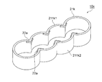
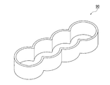
- the groove-shaped cooling water flow path of the cylinder block shown in FIG. 1 has a shape that surrounds the cylinder bore, such as a water jacket spacer 90 shown in FIG. 63, that is, a cylinder that is constricted at three positions corresponding to the cylinder bores.
- Water jacket spacer was installed.
- the water jacket spacer described in the cited document 1 has a shape surrounding the cylinder bore.
- Such a water jacket spacer is manufactured by injection molding of synthetic resin.
- a water jacket spacer having a shape corresponding to a part of the entire flow path is required in the circumferential direction of the grooved cooling water flow path.
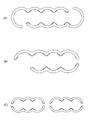
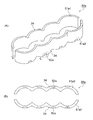
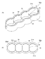
- the water jacket spacer 91 shown in FIG. The water jacket spacer 91 has a shape corresponding to one half of all the circumferential flow paths of the groove-shaped cooling water flow paths of the cylinder block shown in FIG. 1, and the water jacket spacer 92 shown in FIG. 64 (B). Is a shape corresponding to a part (for two intermediate bores) on one side of all the circumferential flow paths of the groove-shaped cooling water flow paths of the cylinder block shown in FIG.
- the water jacket spacer having such a shape is also manufactured by injection molding. And, in the injection molding of the water jacket spacer having such a shape, it is efficient in production to mold in such a shape that the inner sides of the two water jacket spacers face each other as shown in FIGS.
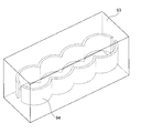
- An injection mold 93 in which a molding space 94 of a molded body in which the inner sides of the two water jacket spacers face each other is used.
- the molding main body in addition to the molding main body, in addition to the spool serving as the molten resin inflow passage from the portion in contact with the nozzle of the injection molding machine to the runner, and the molten resin from the spool to the gate A runner serving as an intermediate passage leading to and a gate serving as an inlet through which the molten resin flows from the runner into the molding space of the molding main body are integrally formed.
- the injection mold is a fixed mold, a movable mold that moves in the vertical direction of the water jacket spacer, and an arrangement of cylinder bores.
- a slide mold that moves in a direction perpendicular to the direction and within an angle of ⁇ 15 ° with respect to a direction perpendicular to the moving direction of the movable mold, and the inner sides of the two water jacket spacers Prepare an injection mold that forms an opposing molding space, clamp the injection mold, then inject a molten synthetic resin, hold the pressure, cool and solidify, then open the mold Then, the method of obtaining a molded object by taking out the molded object sticking to a movable mold
- the molding main body part before the mold opening is attached to the injection molding mold, when the mold is opened, it is perpendicular to the direction in which the cylinder bores are aligned and perpendicular to the moving direction of the movable mold.
- the slide type moving in a direction having an angle within ⁇ 15 ° moves in a direction perpendicular to the direction in which the cylinder bores are aligned and in a direction having an angle within ⁇ 15 ° with respect to the direction perpendicular to the moving direction of the movable type.
- the molding main body is pulled by the slide mold.
- both ends of the two water jacket spacers are not connected to each other. Sticking to the mold causes “slide removal” to occur in the slide mold.
- injection molding is usually controlled by a computer so that automatic operation is performed from mold clamping to injection, pressure holding, cooling and solidification, mold opening, and removal of the molded body. It is programmed to attach the body to the movable mold and take out the molded body adhered to the movable mold. For this reason, if the “slide is taken” occurs, normal operation cannot be performed.
- an object of the present invention is to “slide” when the mold is opened in the production by injection molding of the water jacket spacer having a shape corresponding to all or a part of all the circumferential flow paths of the grooved cooling water flow path. It is an object of the present invention to provide a method for manufacturing a water jacket spacer that does not generate water.
- the water jacket spacers installed in all or a part of all the circumferential flow paths of the groove-shaped cooling water flow paths of the cylinder block of the internal combustion engine having the cylinder bores are injected with synthetic resin. It is a manufacturing method of a water jacket spacer manufactured by molding,
- the injection molding includes a mold clamping process for clamping an injection mold, an injection process for injecting a molten synthetic resin, a solidification process for holding and cooling and solidifying, and a mold for opening the injection mold.
- the injection mold includes a fixed mold, a movable mold that moves in the vertical direction of the water jacket spacer, and within ⁇ 15 ° with respect to a direction perpendicular to the direction in which the cylinder bores are arranged and perpendicular to the moving direction of the movable mold.
- a first water jacket spacer and a second water jacket spacer which have at least one slide mold (1) which moves in an angled direction, and which are opposed to each other at least by the mold clamping in the mold clamping step.
- an all-around water jacket spacer and an undercut portion formed in one or both of the opposing portions of the water jacket spacer and serving as an undercut with respect to the moving direction of the slide mold (1) An injection mold in which a molding space of a molded body is formed, In the mold opening step, the movable mold is moved in the vertical direction of the water jacket spacer, and the slide mold (1) is moved in a direction perpendicular to the cylinder bore arrangement direction and perpendicular to the movable mold moving direction. Opening the injection mold by moving it in a direction having an angle of ⁇ 15 ° or less, The manufacturing method of the water jacket spacer characterized by these is provided.
- a water jacket spacer installed in a part of all the circumferential flow paths of the groove-shaped cooling water flow path of the cylinder block of the internal combustion engine having the cylinder bore is formed by injection molding of synthetic resin. It is a manufacturing method of a water jacket spacer to manufacture,
- the injection molding includes a mold clamping process for clamping an injection mold, an injection process for injecting a molten synthetic resin, a solidification process for holding and cooling and solidifying, and a mold for opening the injection mold.
- the injection mold includes a fixed mold, a movable mold that moves in the vertical direction of the water jacket spacer, and within ⁇ 15 ° with respect to a direction perpendicular to the direction in which the cylinder bores are arranged and perpendicular to the moving direction of the movable mold.
- a first water jacket spacer and a second water jacket spacer which have at least one slide mold (1) which moves in an angled direction, and which are opposed to each other at least by the mold clamping in the mold clamping step.
- the injection mold further includes at least an inner side and a lower side at a lower end of one or both of the first water jacket spacer and the second water jacket spacer.
- a method for producing a water jacket spacer characterized in that a forming space of a formed body having a thin portion formed by the movable mold on the outside is formed.
- the all-around water jacket spacer installed in all the circumferential flow paths of the groove-shaped cooling water flow path of the cylinder block of the internal combustion engine having the cylinder bore is formed by injection molding of synthetic resin. It is a manufacturing method of a water jacket spacer to manufacture,
- the injection molding includes a mold clamping process for clamping an injection mold, an injection process for injecting a molten synthetic resin, a solidification process for holding and cooling and solidifying, and a mold for opening the injection mold.
- the injection mold includes a fixed mold, a movable mold that moves in the vertical direction of the water jacket spacer, and within ⁇ 15 ° with respect to a direction perpendicular to the direction in which the cylinder bores are arranged and perpendicular to the moving direction of the movable mold.
- An all-around water jacket spacer having at least one slide mold (1) that moves in a direction having an angle, and having at least one shape surrounding the cylinder bore wall by clamping in the clamping step; An undercut portion that protrudes from the inside of each one or both of the opposing portions of the mold water jacket spacer or from the inside of each bore portion, and is undercut with respect to the moving direction of the slide die (1)
- the injection mold further includes a movable mold at least on the inner side, the lower side, and the outer side at the lower end of one or both of the opposed portions of the all-around water jacket spacer.
- a method for producing a water jacket spacer according to (4) is provided, in which a molding space for a molded body having a thin-walled portion is formed.
- the present invention (6) provides the method for producing a water jacket spacer according to any one of (2) to (5), characterized in that the protruding portion is provided on the inner side and the upper part of the portion between the bores of the water jacket spacer. To do.
- this invention (7) has the said protrusion part inside each bore part of the said water jacket spacer, and this extension part is formed under the horizontal rib provided in the upper part of each said bore part.
- a water jacket spacer manufacturing method according to any one of (2) to (5) is provided.
- a water jacket spacer installed in a part of all circumferential flow paths of the groove-shaped cooling water flow path of the cylinder block of the internal combustion engine having the cylinder bore is formed by injection molding of synthetic resin. It is a manufacturing method of a water jacket spacer to manufacture,
- the injection molding includes a mold clamping process for clamping an injection mold, an injection process for injecting a molten synthetic resin, a solidification process for holding and cooling and solidifying, and a mold for opening the injection mold.
- the injection mold includes a fixed mold, a movable mold that moves in the vertical direction of the water jacket spacer, and within ⁇ 15 ° with respect to a direction perpendicular to the direction in which the cylinder bores are arranged and perpendicular to the moving direction of the movable mold.
- a first water jacket spacer and a second water jacket spacer which have at least one slide mold (1) which moves in an angled direction, and which are opposed to each other at least by the mold clamping in the mold clamping step. And at least one of the first water jacket spacer and the second water jacket spacer, or a thin wall portion formed by the movable mold on the lower side and the outer side at the lower end.
- An injection mold in which a molding space is formed In the mold opening step, the movable mold is moved in the vertical direction of the water jacket spacer, and the slide mold (1) is moved in a direction perpendicular to the cylinder bore arrangement direction and perpendicular to the movable mold moving direction. Opening the injection mold by moving it in a direction having an angle of ⁇ 15 ° or less, A method for manufacturing a water jacket spacer according to claim 1 is provided.
- an all-around water jacket spacer installed in all the circumferential flow paths of the groove-shaped cooling water flow path of the cylinder block of the internal combustion engine having the cylinder bore is formed by injection molding of synthetic resin. It is a manufacturing method of a water jacket spacer to manufacture,
- the injection molding includes a mold clamping process for clamping an injection mold, an injection process for injecting a molten synthetic resin, a solidification process for holding and cooling and solidifying, and a mold for opening the injection mold.
- the injection mold includes a fixed mold, a movable mold that moves in the vertical direction of the water jacket spacer, and within ⁇ 15 ° with respect to a direction perpendicular to the direction in which the cylinder bores are arranged and perpendicular to the moving direction of the movable mold.
- An all-around water jacket spacer having at least one slide mold (1) that moves in a direction having an angle, and having at least one shape surrounding the cylinder bore wall by clamping in the clamping step; Injection molding in which a molding space of a molded body having at least the inner side, the lower side, and the outer side formed by the movable mold is formed at the lower end of one or both of the opposing portions of the mold water jacket spacer.
- Type In the mold opening step the movable mold is moved in the vertical direction of the water jacket spacer, and the slide mold (1) is moved in a direction perpendicular to the cylinder bore arrangement direction and perpendicular to the movable mold moving direction. Opening the injection mold by moving it in a direction having an angle of ⁇ 15 ° or less, A method for manufacturing a water jacket spacer according to claim 1 is provided.
- the injection mold further includes the inner sides of the first water jacket spacer and the second water jacket spacer facing each other, or the inner sides of the facing portions of the all-around water jacket spacer.
- a method for producing a water jacket spacer according to any one of (1) to (9) is provided, wherein a molding space of a molded body having a bridge portion connecting the two is formed.
- the present invention (11) can provide a water jacket spacer characterized by having an overhanging portion inside and above the bore portion of the water jacket spacer.
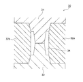
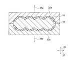
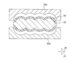
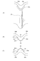
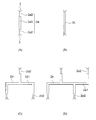
- FIG. 9 is an enlarged view of a portion A in FIG. It is a typical end view which shows the process of the injection molding in the manufacturing method of the water jacket spacer of this invention. It is a typical end view which shows the process of the injection molding in the manufacturing method of the water jacket spacer of this invention. It is a typical end view which shows the process of the injection molding in the manufacturing method of the water jacket spacer of this invention. It is a typical end view which shows the process of the injection molding in the manufacturing method of the water jacket spacer of this invention.
- a manufacturing method (1) of a water jacket spacer it is a mimetic diagram showing an example of a form of a forming object formed in an injection mold. It is the figure which expanded each bore part 24m of the water jacket spacer in FIG. It is the figure which expanded each bore part 24m of the water jacket spacer in FIG. It is an enlarged view of the overhang
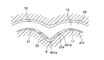
- FIG. 38 It is a schematic diagram of the vicinity of the portion between the bores in a state where the water jacket spacer in which the protruding portion is formed inside the portion between the bores is installed in the groove-shaped cooling water flow path. It is the figure which looked at the wall surface 18 on the opposite side to the wall surface of the inside of a water jacket spacer in FIG. 38, and the cylinder bore side of a groove-shaped cooling water flow path.
- a manufacturing method (1) of a water jacket spacer it is a mimetic diagram showing an example of a form of a forming object formed in an injection mold.
- a manufacturing method (2) of a water jacket spacer it is a mimetic diagram showing an example of a form of a forming object formed in an injection mold.
- a manufacturing method (3) of a water jacket spacer it is a mimetic diagram showing an example of a form of a forming object formed in an injection mold. It is an enlarged view of C part in FIG. It is a typical end view which shows the process of injection molding in the manufacturing method (3) of a water jacket spacer.
- a manufacturing method (3) of a water jacket spacer it is a mimetic diagram showing an example of a form of a forming object formed in an injection mold.
- the manufacturing method of the water jacket spacer of this invention it is a schematic diagram which shows the example of a form of the molded object formed in an injection mold.
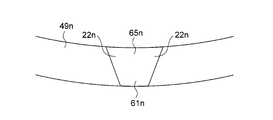
- a manufacturing method (1) of a water jacket spacer it is a mimetic diagram showing an example of a form of a forming object formed in an injection mold. It is the figure which expanded each bore part 24n of the water jacket spacer in FIG. It is the figure which expanded each bore part 24n of the water jacket spacer in FIG. It is an enlarged view of the overhang
- the method for producing a water jacket spacer according to the present invention includes a water jacket spacer installed in all or a part of all the circumferential flow paths of a groove-shaped cooling water flow path of a cylinder block of an internal combustion engine having a cylinder bore.
- Water jacket spacer manufacturing method manufactured by injection molding of The injection molding includes a mold clamping process for clamping an injection mold, an injection process for injecting a molten synthetic resin, a solidification process for holding and cooling and solidifying, and a mold for opening the injection mold.
- the injection mold includes a fixed mold, a movable mold that moves in the vertical direction of the water jacket spacer, and within ⁇ 15 ° with respect to a direction perpendicular to the direction in which the cylinder bores are arranged and perpendicular to the moving direction of the movable mold.
- a first water jacket spacer and a second water jacket spacer which have at least one slide mold (1) which moves in an angled direction, and which are opposed to each other at least by the mold clamping in the mold clamping step.
- an all-around water jacket spacer and an undercut portion formed in one or both of the opposing portions of the water jacket spacer and serving as an undercut with respect to the moving direction of the slide mold (1) An injection mold in which a molding space of a molded body is formed, In the mold opening step, the movable mold is moved in the vertical direction of the water jacket spacer, and the slide mold (1) is moved in a direction perpendicular to the cylinder bore arrangement direction and perpendicular to the movable mold moving direction. Opening the injection mold by moving it in a direction having an angle of ⁇ 15 ° or less, This is a method for manufacturing a water jacket spacer.
- the water jacket spacer manufacturing method of the present invention uses an injection mold in which an undercut portion that is undercut with respect to the moving direction of the slide mold (1) is formed on a molded body formed by injection molding. And a method of manufacturing a water jacket spacer for injection molding. And in the manufacturing method of the water jacket spacer of this invention, the injection molding die by which the undercut part used as an undercut with respect to the moving direction of a slide type
- the water jacket spacer manufactured by the method for manufacturing a water jacket spacer according to the present invention is a water jacket spacer that is installed in a grooved cooling water flow path after a heat-retaining rubber member and its accessory members are attached to the inside.
- it may be a water jacket spacer that is installed in the grooved cooling water flow path without attaching a heat retaining rubber member or the like inside.
- the water jacket spacer manufacturing method of the first aspect of the present invention (hereinafter also referred to as water jacket spacer manufacturing method (1)) is a circumferential direction of a grooved cooling water passage of a cylinder block of an internal combustion engine having a cylinder bore.
- a water jacket spacer manufacturing method for manufacturing a water jacket spacer installed in a part of all the flow paths by injection molding of synthetic resin The injection molding includes a mold clamping process for clamping an injection mold, an injection process for injecting a molten synthetic resin, a solidification process for holding and cooling and solidifying, and a mold for opening the injection mold.
- the injection mold includes a fixed mold, a movable mold that moves in the vertical direction of the water jacket spacer, and within ⁇ 15 ° with respect to a direction perpendicular to the direction in which the cylinder bores are arranged and perpendicular to the moving direction of the movable mold.
- a first water jacket spacer and a second water jacket spacer which have at least one slide mold (1) which moves in an angled direction, and which are opposed to each other at least by the mold clamping in the mold clamping step.
- FIG. 1 is a schematic plan view showing an example of a cylinder block in which a water jacket spacer manufactured by the method for manufacturing a water jacket spacer according to the present invention is installed.
- 2 to 7 and 10 are schematic end views showing the steps of injection molding in the manufacturing method (1) of the water jacket spacer.
- FIG. 8 is a schematic view showing a form example of a molded body formed in an injection mold in the water jacket spacer manufacturing method (1)
- FIG. 8 (A) is a perspective view
- FIG. 8 (B) Is a view from above.
- 9 is an enlarged view of a portion A surrounded by a dotted line in FIG. 8B
- FIG. 9A is a perspective view
- FIG. 9B is a view seen from above.
- (C) is a view from below.
- a water jacket spacer 10a in FIG. 8 is installed in the cylinder block 11 shown in FIG.
- a molded body 10a shown in FIG. 8 is a molded body formed in an injection mold at the time of injection molding in the embodiment of the water jacket spacer manufacturing method (1). It is.
- a water jacket spacer 21 in FIG. 8 is a water jacket spacer installed in an open deck type cylinder block 11 of the vehicle-mounted internal combustion engine as shown in FIG.
- the cylinder block 11 is formed with a bore 12 for moving the piston up and down, and a grooved cooling water flow path 14 for flowing cooling water.
- a wall that separates the bore 12 and the grooved coolant flow path 14 is a cylinder bore wall 13.
- the cylinder block 11 is formed with a cooling water supply port 15 for supplying cooling water to the grooved cooling water flow channel 11 and a cooling water discharge port 16 for discharging cooling water from the grooved cooling water flow channel 11. ing.
- the cylinder block 11 is formed so that two or more bores 12 are arranged in series. Therefore, the bore 12 has end bores 12a1 and 12a2 adjacent to one bore and intermediate bores 12b1 and 12b2 sandwiched between the two bores (note that the number of bores in the cylinder block is two). In the case, only the end bore.) Of the bores arranged in series, the end bores 12a1 and 12a2 are bores at both ends, and the intermediate bores 12b1 and 12b2 are bores between the end bore 12a1 at one end and the end bore 12a2 at the other end.
- a wall between the bores for example, a wall between the end bore 12a1 and the intermediate bore 12b1 is an inter-bore wall 7, and the inter-bore wall 7 is a portion sandwiched between the two bores. Because it is transmitted, the wall temperature is higher than other walls. Further, in the wall surface 17 on the cylinder bore side of the grooved cooling water flow path 14, the boundary of each bore is the boundary 6 of each bore on the wall surface 17 on the cylinder bore side of the grooved cooling water flow path 14.
- the wall surface on the cylinder bore 13 side is described as the wall surface 17 on the cylinder bore side of the grooved cooling water flow path
- a wall surface on the opposite side of the wall surface 17 on the cylinder bore side of the groove-shaped cooling water passage is referred to as a wall surface 18.
- one half of all the circumferential flow paths of the grooved cooling water flow path is when the entire flow path of the grooved cooling water flow path is vertically divided into two in the direction in which the cylinder bores are aligned. Refers to the half of the flow path on one side.
- the direction in which the cylinder bores are lined up is the ZZ direction
- each of the groove cooling water passages on one half when vertically divided by the ZZ line is a groove cooling water passage. It is the flow path of the one side half part of all the flow paths of the circumferential direction.
- the flow path on the 20a side of the ZZ line is the flow path 141a on one half side of all the circumferential flow paths of the grooved coolant flow path, and the flow on the 20b side half.
- the path is the other half-side channel 141b of all the circumferential channels of the grooved coolant channel.
- one side of all the circumferential flow paths of the groove-shaped cooling water flow path indicates either one half-side flow path 141a or one half-side flow path 141b.
- the water jacket spacer 21 is a water jacket spacer that is installed in the groove cooling water channel 141a on one half of all the circumferential channels of the groove cooling water channel 14 of the cylinder block 11 shown in FIG.
- Other examples of the water jacket spacer installed in the groove-shaped cooling water flow path 14 of the cylinder block 11 include, for example, the other half of the groove-shaped cooling water flow in the circumferential direction of the groove-shaped cooling water flow path 14.
- a water jacket spacer installed in the passage 141b, a part of one side 141a or one side 141b of the grooved cooling water passage 14, a passage on the cylinder bores 12a1 and 12b1, a passage on the cylinder bores 12b2 and 12a2, and a cylinder bore 12a1 12b1 and 12b2 side flow passages, cylinder bores 12b1, 12b2 and 12a2 side flow passages, cylinder bore 12a1 side flow passages, cylinder bore 12b1 side flow passages, cylinder bore 12b2 side flow passages, cylinder bore 12a2 side flow passages, cylinder bore 12a2 side flow passages
- One side 141 in addition to all or part of one side 141a of the channel portion and the grooved cooling water channel 14 Water jacket spacer is installed a flow passage component or the like over a part of the like.
- the water jacket spacer 21 is manufactured by injection molding a synthetic resin.
- injection molding in the manufacture of the water jacket spacer 21 as shown in FIG. 8, formation of a molded body 10 a having at least two water jacket spacers 21 facing inside and an overhanging portion 22 having an undercut portion.
- An injection mold in which a space is formed is used as a mold for injection molding.
- FIGS. 2 to 7 and 10 are schematic views showing the state of injection molding performed in the water jacket spacer manufacturing method (1).
- the injection mold 30 is clamped.
- the injection mold 30 includes a fixed mold 31, slide molds (1) 32 a and 32 b, and a movable mold 33.
- the injection mold 30 is an injection mold in which at least the formation space 34 of the molded body 10 is formed by clamping in the mold clamping step.
- the fixed mold 31, the slide molds (1) 32 a and 32 b, and the movable mold 33 are the mold of the molded body 10.
- 2 to 5 are views showing the state of injection molding at an end face position cut by a plane perpendicular to the arrangement direction of the cylinder bores at a position where no projecting portion is formed.
- 6 and 7 are end views taken along line YY in FIG.
- the synthetic resin in a molten state is injected into the forming space 34 of the molded body, cooled in a pressure-holding state, and the synthetic resin is solidified. To form the molded body 10.
- the injection mold 30 is opened.
- the movable mold 33 is moved in the vertical direction 35 of the water jacket spacer and in the direction 351 away from the fixed mold 31, and the slide mold (1) 32a, 32b is moved in directions 38a and 38b perpendicular to the direction in which the cylinder bores are arranged and perpendicular to the moving direction of the movable mold 33, and the slide molds (1) 32a and 32b are moved away from the molded body 10.
- the fixed mold 31 and the slide molds (1) 32a and 32b are detached from the molded body 10.
- the movable mold 33 is further moved in the vertical direction 35 of the water jacket spacer and in the direction away from the fixed mold 31 from the movable mold 33 to a position where the molded body 10 can be taken out.
- the injection mold 30 is opened. Then, after the mold opening of the injection mold 30 is performed, the molded body 10 attached to the movable mold 33 is removed from the movable mold 33, whereby the molded body 10 is taken out from the injection mold 30 and the molded body 10 is removed. Get.
- the direction indicated by reference numeral 35 is the vertical direction of the water jacket spacer. 6 and 7, the direction indicated by reference numeral 37 is the direction in which the cylinder bores are arranged. 3 to 7, the direction indicated by reference numeral 36 is a direction perpendicular to the direction in which the cylinder bores are arranged and perpendicular to the moving direction of the movable mold 33.
- the direction indicated by reference numeral 351 is the moving direction of the movable mold 33 in the mold opening process
- the directions indicated by reference numerals 38a and 38b are the slide molds (1) 32a and 32b in the mold opening process. Each moving direction.
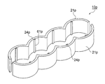
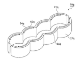
- the molded body 10 is a molded body formed in the injection mold according to the manufacturing method (1) of the water jacket spacer. As shown in FIG. It has at least an overhanging portion 22 projecting from the inside of each bore portion of the two water jacket spacers 21 or from the inside of each bore portion.
- each water jacket spacer 21 in the molded body 10 has a shape in which four arcs are connected when viewed from above.
- Each arc portion of the water jacket spacer 21 is each bore portion 24 of the water jacket spacer on the bore wall side of each cylinder bore.
- the bore portions 24a of the water jacket spacer 21 are located on the bore wall side of the cylinder bore 12a1.
- Each bore portion 24c is positioned on the bore wall side of the cylinder bore 12b1, and each bore portion 24d is positioned on the bore wall side of the cylinder bore 12a2.
- the water jacket spacer 21 has a projecting portion 22 a that projects from the inside of the inter-bore portion 23 and a projecting portion 22 b that projects from the inside of the end of each bore portion 24.
- the boundary 6 of each bore and the vicinity thereof are portions corresponding to the lateral side of the inter-bore wall 7.
- the inner side of each of the bores of the wall surface 17 on the cylinder bore side of the grooved cooling water flow path 14 is opposed to the boundary 6 and the vicinity thereof between the bores of the water jacket spacer 21. This is referred to as part 23.
- the boundary between the adjacent bore portions 24 of the water jacket spacer 21 is referred to as the boundary 25 of each bore portion of the water jacket spacer 21.
- the boundary 25 and its vicinity of each bore part is a portion facing the boundary 6 and its vicinity of each bore of the wall surface 17 on the cylinder bore side of the grooved cooling water flow path 14. This is the inter-bore portion 23 of the jacket spacer.
- the part which opposes each bore part of the wall surface 17 by the side of the cylinder bore of the groove-shaped cooling water flow path 14 among water jacket spacers is called each bore part 24 of a water jacket spacer.
- the overhanging portion 22 a is formed on the inside and top of the inter-bore portion 23 of the water jacket spacer 21 so as to overhang from the inside of the inter-bore portion 23 when viewed from above.
- the overhanging portion 22 is moved when the slide mold (1) moves in a direction perpendicular to the direction in which the cylinder bores are arranged and within ⁇ 15 ° with respect to the direction perpendicular to the moving direction of the movable mold.
- an undercut portion 271 that is an undercut with respect to the moving direction of the slide mold (1) is provided.
- the slide mold (1) is a direction that is perpendicular to the direction in which the cylinder bores are aligned and that is within ⁇ 15 ° with respect to the direction perpendicular to the moving direction of the movable mold, and is a direction away from the molded body.
- the water jacket spacer 21 remains in the movable mold without being taken by the slide mold (1). Further, in the take-out process, the water jacket spacer 21 is moved in the vertical direction of the water jacket spacer to take out the water jacket spacer 21 from the movable mold, but when the water jacket spacer 21 is taken out from the movable mold to the overhanging portion 22a. There is no undercut. Therefore, in the removal process, the water jacket spacer 21 can be removed from the movable mold.
- FIG. 10 shows a state where the overhang portion 22a is formed by injection molding.
- the overhang portion 22a is formed at a portion where the fixed die 31 and the movable die 33 are combined.
- FIG. 10 is a view showing a state of injection molding at an end face position cut by a plane perpendicular to the arrangement direction of the cylinder bores at a position where the projecting portion is formed.
- the water jacket spacer manufacturing method (1) includes a water jacket spacer installed in a part of all the circumferential flow paths of the groove-shaped cooling water flow paths of the cylinder block of the internal combustion engine having the cylinder bores. It is a manufacturing method of a water jacket spacer manufactured by injection molding of synthetic resin,
- the injection molding includes a mold clamping process for clamping an injection mold, an injection process for injecting a molten synthetic resin, a solidification process for holding and cooling and solidifying, and a mold for opening the injection mold.
- the injection mold includes a fixed mold, a movable mold that moves in the vertical direction of the water jacket spacer, and within ⁇ 15 ° with respect to a direction perpendicular to the direction in which the cylinder bores are arranged and perpendicular to the moving direction of the movable mold.
- a first water jacket spacer and a second water jacket spacer which have at least one slide mold (1) which moves in an angled direction, and which are opposed to each other at least by the mold clamping in the mold clamping step.
- the cylinder block on which the water jacket spacer manufactured by the water jacket spacer manufacturing method (1) is installed is an open deck type cylinder block in which two or more cylinder bores are arranged in series.
- the cylinder block has a cylinder bore composed of two end bores.
- the cylinder block is an open deck type cylinder block in which three or more cylinder bores are arranged in series, the cylinder block has a cylinder bore composed of two end bores and one or more intermediate bores. ing.
- the bores at both ends are called end bores
- the bores sandwiched between the other cylinder bores are called intermediate bores.
- the water jacket spacer manufactured by the manufacturing method (1) of the water jacket spacer is installed in a part of all the circumferential flow paths of the groove-shaped cooling water flow paths of the cylinder block. Therefore, the water jacket spacer manufactured by the manufacturing method (1) of the water jacket spacer has a shape composed of one arc or a shape in which two or more arcs are connected when viewed from above.
- the water jacket spacer manufactured by the manufacturing method (1) of the water jacket spacer when viewed from above, how many arcs are formed and which groove-shaped cooling water flow path has a shape to be installed This is appropriately selected depending on the number of cylinder bores formed in the cylinder block, the location where the flow of cooling water is desired to be changed, and the like.
- the molding space of the molded object in an injection mold is designed according to the shape of the water jacket spacer made into the manufacturing objective.
- the water jacket spacer is manufactured by injection molding of synthetic resin.
- Injection molding includes a clamping process for clamping an injection mold, an injection process for injecting a molten synthetic resin into the molding space of the molded body, and a molten synthetic resin injected into the molding space of the molded body. It consists of a solidification process in which it is pressed and cooled to solidify, a mold opening process in which the mold of the injection mold is opened, and a process of taking out the molded body from the injection mold.
- An injection mold used for injection molding according to the water jacket spacer manufacturing method (1) is an injection mold in which a molding space for a molded body is formed in the mold by clamping in the clamping process.
- An injection mold used for injection molding according to the water jacket spacer manufacturing method (1) includes a fixed mold, a movable mold that moves in the vertical direction of the water jacket spacer and away from the fixed mold when the mold is opened, One or more slide molds (1) that move in a direction perpendicular to the direction in which the cylinder bores are arranged and within an angle of ⁇ 15 ° with respect to a direction perpendicular to the movable movement direction.
- the inner side of the water jacket spacer is the side of the water jacket spacer that faces the wall surface on the cylinder bore side of the grooved cooling water flow path
- the outer side of the water jacket spacer is the water jacket spacer.
- slide mold (1) a slide mold that moves in a direction perpendicular to the direction in which the cylinder bores are aligned and within an angle of ⁇ 15 ° with respect to a direction perpendicular to the moving direction of the movable mold.
- the slide mold (1) has an undercut with respect to the moving direction of the movable mold on the outside of the first water jacket spacer or the second water jacket spacer of the molded body, and is perpendicular to the direction in which the cylinder bores are arranged.
- the first water jacket of the molded body is a portion that does not become AND-cut with respect to the moving direction of the slide mold (1) that moves in a direction having an angle within ⁇ 15 ° with respect to the direction perpendicular to the moving direction of the movable mold. This is a mold for forming on the outside of the spacer or the second water jacket spacer.
- the injection mold is a mold that forms a molded body, a movable mold that moves in the vertical direction of the fixed mold and the water jacket spacer, and ⁇ 15 with respect to the direction perpendicular to the moving direction of the movable mold and perpendicular to the direction in which the cylinder bores are arranged.
- At least one slide mold (1) that moves in a direction having an angle of less than 0 °, and if necessary, a mold that forms a molded body other than those, such as a cylinder bore arrangement direction and a movable mold Slide type that moves in a direction that has an angle within ⁇ 15 ° with respect to the direction perpendicular to the moving direction (hereinafter also referred to as other slide type (2)), angle that is less than 90 ° with respect to the direction in which the cylinder bores are arranged And a slide type that moves in a direction having an angle within ⁇ 15 ° with respect to a direction perpendicular to the moving direction of the movable type (hereinafter also referred to as other slide type (3)). It can be.
- a mold for forming a molded body is a fixed mold, a movable mold that moves in the vertical direction of the water jacket spacer, and a cylinder bore.
- an injection molded body composed of two slide molds (1) that move in a direction perpendicular to the alignment direction and within an angle of ⁇ 15 ° with respect to a direction perpendicular to the moving direction of the movable mold.
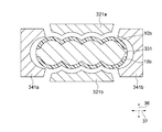
- a mold for forming a molded body is a fixed mold (not shown in the figure), a movable mold 331, and a slide.
- the movable mold 331 moves in the vertical direction of the water jacket spacer (in FIG. 11 and FIG. 12, the reverse direction of the paper surface), and the slide molds (1) 321a and 321b move in the direction in which the cylinder bores are aligned.
- 341b are directions having an angle within ⁇ 15 ° with respect to the direction in which the cylinder bores are arranged and perpendicular to the moving direction of the movable mold, and move in directions 391a and 391b away from the molded body 10b.
- This other slide mold (2) is undercut with respect to the movable mold on the outside of the first water jacket spacer or the second water jacket spacer of the molded body, and is perpendicular to the alignment direction of the cylinder bores and movable.
- the direction is perpendicular to the direction in which the cylinder bores are arranged and the movable type is moved.
- the other slide mold (2) that moves in a direction having an angle of ⁇ 15 ° or less, it is a mold for forming a portion that does not become an AND cut.
- the mold forming the molded body is a fixed mold, a movable mold that moves in the vertical direction of the water jacket spacer, and a movable mold that is perpendicular to the alignment direction of the cylinder bores and movable.
- Two slide molds (1) that move in a direction having an angle within ⁇ 15 ° with respect to the direction perpendicular to the direction, and an angle within ⁇ 15 ° with respect to the direction in which the cylinder bores are aligned and the direction perpendicular to the movable movement direction
- An injection-molded body composed of two slide molds (2) that move in a direction including
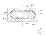
- a mold for forming a molded body is a fixed mold (not shown in the figure), a movable mold 332, and a slide.
- the movable mold 332 moves in the vertical direction of the water jacket spacer (in FIG. 13 and FIG. 14, the back direction of the paper surface), and the slide molds (1) 322a and 322b move in the direction in which the cylinder bores are aligned.
- a direction perpendicular to the moving direction of the movable mold and an angle within ⁇ 15 ° with respect to the movable mold 10c moves in the directions 382a and 382b away from the molded body 10c, and is another slide mold (2) 342a. Is a direction having an angle within ⁇ 15 ° with respect to the direction in which the cylinder bores are aligned and the direction perpendicular to the moving direction of the movable mold, and moves in a direction 392a away from the molded body 10c.
- the mold forming the molded body is a fixed mold, a movable mold that moves in the vertical direction of the water jacket spacer, and a movable mold that is perpendicular to the alignment direction of the cylinder bores and movable.
- Two slide molds (1) that move in a direction having an angle within ⁇ 15 ° with respect to the direction perpendicular to the direction, and an angle within ⁇ 15 ° with respect to the direction in which the cylinder bores are aligned and the direction perpendicular to the movable movement direction
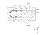
- a mold for forming a molded body is a fixed mold (not shown in the figure), a movable mold 333, and a slide.
- An injection mold composed of the molds (1) 323a and 323b is exemplified.
- the movable mold 333 moves in the vertical direction of the water jacket spacer (in FIG. 15 and FIG. 16, the back direction of the paper surface), and the slide molds (1) 323a and 323b move in the direction in which the cylinder bores are aligned.
- the movable mold is not only the inner part of the water jacket spacer but also a part of the outer part, and the movable mold is formed on the outer part of the water jacket spacer.
- a movable mold that is not only the inner side of the water jacket spacer but also a part of the outer side can be used as the movable mold.
- the mold forming the molded body is a fixed mold, a movable mold that moves in the vertical direction of the water jacket spacer, and a movable mold that is perpendicular to the alignment direction of the cylinder bores and movable. It consists of two slide molds (1) that move in a direction having an angle of ⁇ 15 ° with respect to the direction perpendicular to the direction, and the movable mold is not only the inner side of the water jacket spacer but also the partial mold on the outer side.
- the injection-molded body which has been mentioned.
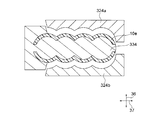
- a mold for forming a molded body is a fixed mold (not shown in the figure), a movable mold 334, and a slide.
- An injection mold composed of the molds (1) 324a and 324b may be mentioned.
- the movable mold 334 moves in the vertical direction of the water jacket spacer (in FIG. 17 and FIG. 18, the reverse direction of the paper surface), and the slide molds (1) 324a and 324b move in the direction in which the cylinder bores are aligned.
- the movable mold 334 is not only the inside of the water jacket spacer but also a part of the outside.
- the mold forming the molded body is a fixed mold, a movable mold that moves in the vertical direction of the water jacket spacer, and a movable mold that is perpendicular to the alignment direction of the cylinder bores and movable.
- a mold for forming a molded body is a fixed mold (not shown in the figure), a movable mold 335, and a slide.
- an injection molding die composed of the die (1) 325a.
- the movable mold 335 moves in the vertical direction of the water jacket spacer (the back direction of the paper surface in FIGS. 19 and 20), and the slide mold (1) 325a moves with respect to the arrangement direction of the cylinder bores. It is a direction having an angle within ⁇ 15 ° with respect to a direction perpendicular to the moving direction of the movable mold, and moves in a direction 385 away from the molded body 10f.
- the movable mold 335 is not only the inside of the water jacket spacer but also the entire mold outside the one water jacket spacer, and the movable mold is the mold.
- the movable mold is the mold.
- an undercut is formed with respect to the movable mold, and a direction perpendicular to the direction in which the cylinder bores are arranged and perpendicular to the moving direction of the movable mold is within ⁇ 15 °.
- the slide mold (1) which is the mold on the outer side of the other water jacket spacer in which the portion that does not become AND-cut is formed can be made one.
- the mold forming the molded body is a fixed mold, a movable mold that moves in the vertical direction of the water jacket spacer, and a movable mold that is perpendicular to the alignment direction of the cylinder bores and movable. It is composed of one slide mold (1) that moves in a direction having an angle within ⁇ 15 ° with respect to the direction perpendicular to the direction, and the movable mold is not only the inside of the water jacket spacer but also all the outside molds.
- the injection-molded body which has been mentioned.
- a part of the water jacket spacer has a movable mold part on the outside.
- the water jacket spacer is attached to the slide mold (1) with a heel and “slide removed” is not caused.
- the “attached member” formed on the outer side of the jacket spacer bites into the slide mold (1) and is strongly pulled by the slide mold (1).
- the direction indicated by reference numeral 37 is the cylinder bore arrangement direction
- the direction indicated by reference numeral 36 is perpendicular to the cylinder bore arrangement direction and perpendicular to the movable movement direction. It is.
- a mold that forms an integrally molded body is a fixed mold 316, a movable mold 336, slide molds (1) 326a, 326b, and the like.
- the movable mold 336 moves in the vertical direction 35 of the water jacket spacer and in the direction 356 away from the fixed mold, and the slide molds (1) 326a and 326b are arranged in the cylinder bores.
- the slide mold (1) is not in the direction perpendicular to the moving direction of the movable mold, but within an angle of ⁇ 15 ° with respect to the direction perpendicular to the moving direction of the movable mold. Move in the direction you have.
- the injection mold used for injection molding according to the water jacket spacer manufacturing method (1) has a fixed mold and a movable mold that moves in the vertical direction of the water jacket spacer, and There is at least one slide mold (1) that moves in a direction perpendicular to the direction in which the cylinder bores are arranged and within an angle of ⁇ 15 ° with respect to a direction perpendicular to the movable movement direction. Which part of the first water jacket spacer and the second water jacket spacer of the molded body becomes the fixed mold and the movable mold depends on the first water jacket spacer and the second water jacket spacer of the molded body.
- the injection mold used for the injection molding according to the manufacturing method (1) of the water jacket spacer preferably has one or two slide molds (1), particularly preferably two.
- the number of the slide molds (1) is specifically undercut with respect to the movable mold by the first water jacket spacer and the second water jacket spacer of the molded body.
- the portion that is not undercut is appropriately selected.
- the injection mold used for the injection molding according to the manufacturing method (1) of the water jacket spacer is arranged in the direction in which the cylinder bores are arranged and movable.
- Other slide molds (2) that move in a direction having an angle of ⁇ 15 ° or less with respect to the direction perpendicular to the moving direction, or movable movements that have an angle of less than 90 ° with respect to the cylinder bore arrangement direction
- Another slide mold (3) that moves in a direction having an angle within ⁇ 15 ° with respect to a direction perpendicular to the direction can be provided.
- the other slide mold (2) and the other slide mold (3) are the first of the molded body. Which part of the water jacket spacer and the second water jacket spacer is to be used is determined by the first water jacket spacer and the second water jacket spacer of the molded body, specifically, an undercut relative to the movable mold.
- the portion that is undercut for the slide mold (1) and that is not undercut for the other slide mold (2) or the other slide mold (3) is the first water of the molded body. It is selected appropriately depending on whether or not it is formed on the jacket spacer and the second water jacket spacer. .
- the moving direction of the slide mold (1) of the injection mold used for the injection molding according to the water jacket spacer manufacturing method (1) is perpendicular to the cylinder bore arrangement direction and perpendicular to the movable mold moving direction.
- the water jacket spacer 21 in the form example in which no member is formed outside the water jacket spacer has been described as an example.
- a portion that is undercut with respect to the moving direction of the movable mold is formed outside the water jacket spacer.
- FIGS. 2 to 7 and FIGS. 11 to 21 an example in which a portion that is undercut with respect to the movable die is formed outside the water jacket spacer for the sake of simplicity.
- a portion that is undercut with respect to the movable mold is formed outside the water jacket spacer. Therefore, since the injection molding cannot be performed only with the fixed mold and the movable mold, the slide mold (1) is necessary, or in addition to the slide mold (1), another slide mold (2) or another slide mold ( 3) etc. are required.
- the mold clamping process is a process in which the injection mold is clamped to form a molding space for the molded body in the injection mold.
- the injection step is a step of injecting the molten synthetic resin into the molding space of the molded body in the injection mold and pouring it into the molding space of the molded body.
- the solidification step is a step in which the synthetic resin injected into the molding space of the molded body in the injection process is cooled and solidified in a pressure-holding state to form a molded body in the molding space of the molded body in the injection mold. It is.
- the mold of the injection mold is opened.
- the movable mold is moved in the vertical direction of the water jacket spacer and in the direction away from the fixed mold, and the slide mold (1) is moved perpendicularly to the cylinder bore arrangement direction and movable.
- the slide mold (1) is moved away from the molded body by moving in a direction having an angle of ⁇ 15 ° with respect to the direction perpendicular to the direction.
- the fixed mold and the slide mold (1) are detached from the molded body.
- the movable mold is further moved in the vertical direction of the water jacket spacer and in the direction away from the fixed mold to a position where the molded body can be taken out from the movable mold. In this way, the mold of the injection mold is opened.
- the taking-out step is a step of taking out the molded body from the injection mold by removing the molded body attached to the fixed mold after the mold opening process.
- the formation space of the molded body formed in the injection mold by the mold clamping in the mold clamping process is such a shape that a molded body described below is formed. That is, in the water jacket spacer manufacturing method (1), an injection mold in which a molding space in which a molded body described below is formed is formed in the mold by clamping is used as the injection mold.
- the molded body formed in the injection mold includes at least a first water jacket spacer and a second water jacket spacer whose inner sides face each other, and a first water jacket.
- An overhanging portion that has an undercut portion that protrudes from the inside of the portion between the bores of either one or both of the spacer and the second water jacket spacer or from the inside of each bore portion, and becomes an undercut with respect to the slide mold (1). And having.
- the first water jacket spacer and the second water jacket spacer of the molded body formed in the injection mold may have the same shape or different shapes. Further, the first water jacket spacer and the second water jacket spacer formed on the molded body may be installed in the groove-shaped cooling water flow path of the same cylinder block, or each of the separate cylinder blocks. It may be installed in the grooved cooling water flow path.
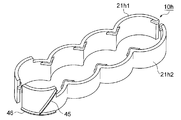
- the molded body 10h may have water jacket spacers 21h1 and 21h2 having different shapes.
- the molded body 10h is formed with a water jacket spacer 21h1 installed in one half of the groove-shaped cooling water flow path of one cylinder block and a water jacket spacer 21h2 installed in the other half of the other.
- the molded body may have two water jacket spacers having the same shape.
- two water jacket spacers installed in the groove-like cooling water flow paths of the respective separate cylinder blocks are formed.
- the molded body may have two water jacket spacers having a different number of bore portions constituting the water jacket spacer in total (for example, an embodiment shown in FIG. 40B).
- the first water jacket spacer and the second water jacket spacer are water jacket spacers installed in a part of all the circumferential flow paths of the groove-shaped cooling water flow paths of the cylinder block
- the first water jacket spacer As the shape of the second water jacket spacer, a shape along one half of all the circumferential flow paths of the groove-shaped cooling water flow path of the cylinder block (for example, a shape like the embodiment shown in FIG. 8).
- a shape along a part of one side for example, a shape like the embodiment shown in FIG. 31
- a shape along one half of one side and a part of the other half of the other side shown in FIG.
- first water jacket spacer and the second water jacket spacer formed on the molded body have a shape in which two or more arcs are connected even when the shape is a single arc when viewed from above. It may be.
- the number of combinations of the first water jacket spacer and the second water jacket spacer of the molded body formed in the injection mold is 1 or more.
- the number of combinations of the first water jacket spacer and the second water jacket spacer is 2 or more.
- the number of the bore portions of the first water jacket spacer and the second water jacket spacer in the molded body is small, the number of combinations of the first water jacket spacer and the second water jacket spacer is two.
- the number of combinations of the first water jacket spacer and the second water jacket spacer in the molded body is 2 or more (for example, the embodiment shown in FIG. 40C).
- the first water jacket spacer and the second water jacket spacer in the molded body have cooling water so that the cooling water supplied to the lower part of the groove-like cooling water flow path flows upward as in the embodiment shown in FIG. Cooling water for preventing the cooling water flow changing member 45 for changing the flow and the cooling water supplied to the lower part of the grooved cooling water flow path from flowing under the water jacket spacer to the inside of the water jacket spacer.
- the inflow prevention member 46 may be provided.
- the first water jacket spacer and the second water jacket spacer in the molded body are attached to the upper side of both sides of the water jacket spacer, for example, a member for preventing the whole from shifting upward, and the upper end is A cylinder head abutting member that abuts on the cylinder head or the cylinder head gasket can be provided.
- the 1st water jacket spacer and 2nd water jacket spacer in a molded object can also have the member etc. for adjusting the flow of other cooling water.
- the overhang portion having an undercut portion formed in the injection mold includes an overhang portion formed inside the bore portion of the water jacket spacer, and the water jacket spacer. And an overhanging portion formed inside each bore portion. Further, the overhang formed on the inner side of the bore portion of the water jacket spacer has a bore portion formed at the end portion of the water jacket spacer, and is formed on the inner side of the bore portion at the end portion. Overhanging portion (hereinafter also referred to as an overhanging portion between the end bores) and an overhanging portion (hereinafter referred to as between the bores) formed inside the inter-bore portion that is not the end of the water jacket spacer. It is also described as a part overhanging part).
- each bore part of the water jacket spacer is each bore part, and is formed at the end part of each bore part that is the end part.
- Overhanging portions hereinafter also referred to as “bore overhanging portions of each end portion” and each bore portion from one bore portion to the other bore portion or from the end portion of the water jacket spacer to the bore portion.
- an overhanging portion hereinafter also referred to as each bore overhanging portion formed on the inside.
- the inter-bore portion of the water jacket spacer is a portion of the water jacket spacer that faces the boundary of each bore of the wall surface on the cylinder bore side of the grooved cooling water flow path and the vicinity thereof.
- each bore portion of the water jacket spacer is a portion of the water jacket spacer that faces each bore portion of the wall surface on the cylinder bore side of the groove-like cooling water flow path, and is circular when viewed from above. It is an arc-shaped part.
- the portions indicated by reference numeral 24 are each bore portion of the water jacket spacer.
- the inter-bore overhanging portion when viewed from above, projects from the inside of the inter-bore portion of the water jacket spacer so as to spread along the inter-bore portion on both sides starting from the boundary of each bore portion.
- the projecting part between the bores is in a direction in which the slide mold (1) has an angle within ⁇ 15 ° with respect to the direction perpendicular to the cylinder bore arrangement direction and the direction perpendicular to the moving direction of the movable mold. It has an undercut part which becomes an undercut with respect to the moving direction of the slide mold (1) when moving and moving away from the molded body.
- Whether or not an undercut occurs in the moving direction of the mold (1) is determined as follows. First, the moving direction of the slide mold (1) at a point on the contour for determining whether or not an undercut is to be determined, and the direction in which the contour extends when viewed in the moving direction of the slide mold (1) are identified.
- the undercut occurs, When the direction in which the contour extends overlaps with the moving direction of the slide mold (1) or is inclined to the side without the resin, the undercut does not occur.
- a set of points on the contour that are undercut is an undercut portion that is undercut with respect to the moving direction of the slide mold (1).
- the direction in which the contour extends is the direction in which the straight line at the point on the determination target contour extends when the contour is a straight line, and when the contour is a curve, the tangent at the point on the determination target contour. Pointing in the direction.
- the resin side means that the resin side is the resin side and the resin-free side is the resin side when viewed in the direction perpendicular to the moving direction of the slide mold (1) at the point on the contour of the judgment object. There is no side.
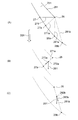
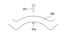
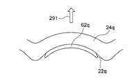
- FIGS. 22 and 23 are enlarged views of the overhanging portion 22a in FIG. 8 as viewed from above, and FIG. 23 is an enlarged view of a portion B in FIG.
- the overhanging portion 22 a is an overbore overhanging portion formed so as to overhang from the inside of the inter-bore portion 23 when viewed from above, on the inner side and the upper portion of the inter-bore portion 23 of the water jacket spacer 21.
- the overhanging portion 22a has an undercut portion 271.
- the undercut portion 271 is perpendicular to the direction in which the slide die (1) is aligned with the cylinder bores and the moving direction of the movable die in the mold opening process.
- the outline of the overhanging portion 22a starts from the position of the boundary 25 of each bore portion of the water jacket spacer 21, passes through the position 26, and is located on the inside of the inter-bore portion 23 at the position 27. Crosses the contour 231.
- the direction in which the contour at the point 26 on the contour extends is the direction from the position 26 toward the position 27.
- the moving direction 291 of the slide mold (1) is a direction facing directly downward from the position 26 on the paper surface of FIG.
- the direction in which the contour at the position 26 extends that is, the direction from the position 26 toward the position 27 is inclined to the resin side with respect to the moving direction 291 of the slide mold (1). Is undercut. The same applies to the points on the contour 271 from the position 26 to the position 27. Therefore, the part which forms the outline 271 from the position 26 to the position 27 is an undercut part.
- the direction 273a in which the contour at the point at the position 272a that is the point on the contour 271a extends is the direction from the position 272a toward the position 27a.
- the moving direction 291 of the slide mold (1) is a direction facing directly downward from the position 272a on the paper surface of FIG.
- the position 272a When the position 272a is viewed in a direction perpendicular to the moving direction 291 of the slide mold (1), there is resin on the left side of the position 272a and there is no resin on the right side. Then, the direction 273a in which the contour at the position 272a extends, that is, the direction from the position 272a toward the position 27a is inclined to the resin side with respect to the moving direction 291 of the slide mold (1), and thus the point 272a on the contour 271a. Is undercut. The same applies to the points on the contour 271a from the position 26 to the position 27a. Therefore, the part which forms the outline 271a from the position 26 to the position 27a is an undercut part.
- FIG. 22 and FIG. 23 assuming that the contour from the position 26 to the contour 231 inside the inter-bore portion 23 is denoted by reference numeral 281a and the point where the contour 231 intersects is 28a, this case is shown in FIG.
- the direction in which the contour at the point on the contour 281a extends is the direction from the position 26 toward the position 28a, that is, the direction facing directly below from the position 26 in the paper surface of FIG.
- the moving direction 291 of the slide mold (1) is a direction facing directly downward from the position 26 on the paper surface of FIG.
- the direction in which the contour at the point on the contour 281a extends that is, the direction from the position 26 to the position 28a overlaps the moving direction 291 of the slide mold (1).
- the points on the contour 281a from the position 26 to the position 28a are not an undercut part.
- the contour from the position 26 to the inner contour 231 of the inter-bore portion 23 is denoted by reference numeral 281b and the point where the contour 231 intersects is denoted by 28b, this case is shown in FIG.
- the direction 283b in which the contour at the point at the position 282b, which is a point on the contour 281b, extends is the direction from the position 282b to the position 28b.
- the moving direction 291 of the slide mold (1) is a direction facing directly downward from the position 282b on the paper surface of FIG.
- the position 282b When the position 282b is viewed in a direction perpendicular to the moving direction 291 of the slide mold (1), there is resin on the left side of the position 282b and there is no resin on the right side. Then, the direction 283b in which the outline at the position 282b extends, that is, the direction from the position 282b to the position 28b is inclined to the side without the resin from the moving direction 291 of the slide mold (1), and thus is on the outline 281b. The point 282b is not undercut. The same applies to the points on the contour 281b from the position 26 to the position 28b. Therefore, the part which forms the outline 281b from the position 26 to the position 28b is not an undercut part.
- the portion of the overhanging portion 22a forming the contour 261 and the contour 271 has a direction in which the contour extends when viewed in the movable movement direction, and therefore overlaps the movable movement direction. Undercut. Therefore, when the water jacket spacer 21 is taken out from the movable die in the take-out step, the water jacket spacer 21 can be taken out from the movable die by moving the water jacket spacer 21 in the vertical direction and away from the movable die.
- the overhanging part between the bores should not have an undercut part with respect to the moving direction of the movable mold in the mold opening process.
- the shape of the projecting portion between the bores when the water jacket spacer is viewed from above is such that the slide mold (1) is perpendicular to the direction in which the cylinder bores are aligned and perpendicular to the moving direction of the movable mold in the mold opening process.
- the shape of each bore overhanging portion is the shape of each bore overhanging portion 22a in the embodiment shown in FIG. 8, or the bore in the embodiment shown in FIG.
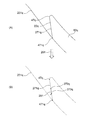
- the contour extending from the position 26 to the inner contour of the inter-bore portion 23 is denoted by reference numeral 271a.
- the contour 271a and the inner contour of the inter-bore portion 23 are shown in FIG. This is a form example when the intersection of 231 is a position 27a. And as mentioned above, the part which forms the outline 271a becomes an undercut part with respect to the moving direction of a slide type
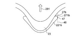
- the contour 271b from the intersection 27b of the contour of the projecting portion and the inner contour of the inter-bore portion 23 to the vicinity thereof is an arcuate curve.
- the tangent line of the contour parallel to the moving direction of the slide mold (1) is a tangent line 48 and the contact point is a contact point 47
- all points on the contour 271b from the contact point 47 to the intersection point 27b are directions in which the contour extends. That is, the direction of the tangent line at that point is inclined to the resin side with respect to the moving direction 291 of the slide mold (1), so that all points on the contour 271b are undercut. Therefore, the part which forms the outline 271b becomes an undercut part with respect to the moving direction of the slide mold (1).
- the inter-bore overhanging portion 221c shown in FIG. 26 is an example in which the overhanging width of the overhanging portion is the same in all portions of the overhanging portion.
- the undercut part 271c is judged similarly to the undercut part 271a of the form example shown in FIG. Therefore, the part which forms the outline 271c becomes an undercut part with respect to the moving direction of the slide mold (1).
- the projecting width of the projecting portion between the bores is appropriately selected depending on the shape of the grooved cooling water flow path of the cylinder block.
- the protruding width increases from the boundary of each bore portion of the water jacket spacer toward the bore center portion.
- the bore center portion of the water jacket spacer refers to the central portion in the arc direction when each bore portion of the water jacket spacer is viewed from above.
- the overhang width of the overhang portion refers to the length from the contour of the water jacket spacer between the bores to the contour of the overbore portion of the water jacket spacer when viewed from above.
- the length indicated by 222 is the overhang width of the inter-bore overhang portion.
- the formation position in the vertical direction of the inter-bore overhanging portion is not particularly limited as long as it is a portion where the fixed mold and the movable mold of the injection mold are combined and the die of the over-bore overhanging portion is formed.
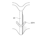
- the vertical position of the overhanging part may be a position closer to the center instead of the upper part of the interbore part 23 as in the inter-bore overhanging part 221d of the embodiment shown in FIG.
- the vertical position of the extension portion may be the lower portion instead of the upper portion of the bore portion 23.
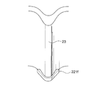
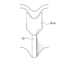
- an inter-bore overhanging part may be formed from the upper part in the vertical direction of the inter-bore part 23 to the vicinity of the center like the overhanging part 221e in the embodiment shown in FIG.
- the end-bore overhanging portion is an overhanging portion that is formed inside the bore-to-bore portion that is the end of the water jacket spacer.
- the end-bore overhanging portion is formed so as to project only from the end of the water jacket spacer and from the inside of the end-bore between the bore portions when viewed from above.
- the projecting part between the end bores has an angle within ⁇ 15 ° with respect to the direction perpendicular to the direction in which the cylinder bores are aligned and the direction perpendicular to the moving direction of the movable mold. It has an undercut part which becomes an undercut with respect to the moving direction of a slide type
- FIG. 31 is a schematic diagram showing a form example of the molded body
- FIG. 31 (A) is a form example in which a bore portion is formed at both ends of the water jacket spacer
- FIG. This is an example in which a bore portion is formed at one end of the water jacket spacer and the other end is each bore portion.
- an inter-bore portion 192 is formed at both ends of the water jacket spacer 21i, and an end-bore overhang portion 22c is formed inside the inter-bore portion 192.
- an inter-bore portion 192 is formed at one end of the water jacket spacer 21j, and an end-bore overhanging portion 22c is formed inside the inter-bore portion 192.
- Both the water jacket spacer 21 i and the water jacket spacer 21 j are formed with an inter-bore overhanging portion 22 a inside the inter-bore portion 23 that is not an end of the water jacket spacer.
- the shape of the inter-bore portion 192 which is the end portion of the water jacket spacer and the end-bore overhanging portion 22c formed inside the inter-bore portion 192 is the water jacket spacer. It is the shape which divided
- the shape of the inter-bore portion 192 which is the end portion of the water jacket spacer and the end-bore overhang portion 22c formed inside the inter-bore portion 192 is the end portion of the water jacket spacer. It is the shape which cut off part of the inter-bore part 23a formed in the inside of the inter-bore part 23 and the inter-bore part 23 which is not bored.
- the overhanging portion 22c between the end bores has an undercut portion 275.
- the undercut portion 275 is movable in a direction perpendicular to the direction in which the cylinder bores are aligned and movable in the mold opening process.
- an undercut is formed with respect to the moving direction of the slide mold (1).
- the determination method of the undercut part in the overhanging part between the end bores is the same as the determination method of the undercut part in the overhanging part between the bores.
- the shape of the projecting portion between the end bores when the water jacket spacer is viewed from above is appropriately selected depending on the shape of the grooved cooling water flow path of the cylinder block. Further, the formation position in the vertical direction and the formation range in the vertical direction of the end bore extension portion are the same as those of the bore extension portion.
- the end bore portions project from the end of the water jacket spacer so as to extend along the bore portions in the direction toward the center of the bore portions when viewed from above.
- the bore part projecting part of the end part has an angle within ⁇ 15 ° with respect to the direction in which the slide mold (1) is perpendicular to the direction in which the cylinder bores are aligned and perpendicular to the moving direction of the movable mold. It has an undercut part which becomes an undercut with respect to the moving direction of a slide type
- the end overhanging portion and the undercut portion will be described more specifically with reference to FIGS. 8 and 31B.
- the end portion 19 of the water jacket spacer 21 is opposed to each bore portion of the cylinder bore wall, and thus corresponds to each bore portion of the water jacket spacer.
- projection part 22b is formed inside the other end 19 corresponded to each said bore part.
- the end 19j of the water jacket spacer 21j faces each bore portion of the cylinder bore wall. It corresponds to the part.
- projection part 22b is formed inside the other end 19j corresponded to each said bore part.
- Each of the end overhang portions 22b has an undercut portion 276.
- the undercut portion 276 has a direction in which the slide die (1) is perpendicular to the direction in which the cylinder bores are aligned and is movable.
- an undercut is formed with respect to the moving direction of the slide mold (1).
- projection part is the same as the determination method of the undercut part in the inter-bore overhang part.
- each bore overhanging portion of the end is appropriately selected depending on the shape of the grooved cooling water flow path of the cylinder block. Further, the formation position in the vertical direction and the formation range in the vertical direction of each bore portion overhanging portion are the same as those in the inter-bore overhanging portion.
- the end portion of the water jacket spacer is not connected to other parts, it is easily deformed so that the end portion of the water jacket spacer is opened outward by being pulled by the slide mold (1) when the mold is opened.
- the mold when the mold is opened, it may be deformed by being pulled by the slide mold (1) in the direction indicated by reference numeral 461 in FIGS. 8 (B), 31 (A), and 31 (B). Therefore, the undercut portion of the end bore portion overhang portion, which is the overhang portion formed on the end portion of the water jacket spacer, and the undercut portion of each end bore portion overhang the slide die (1) when the mold is opened. It is preferable that the undercut is also made in the deformation direction of the end portion of the water jacket spacer when pulled.
- each bore extension portion is formed in one or more positions at any position in the arc direction of each bore portion of the water jacket spacer when viewed from above.
- each bore portion overhanging portion has a direction in which the slide die (1) has an angle within ⁇ 15 ° with respect to the direction perpendicular to the cylinder bore arrangement direction and the direction perpendicular to the moving direction of the movable die. It has an undercut part which becomes an undercut with respect to the moving direction of the slide mold (1) when moving and moving away from the molded body.
- FIG. 32 is a schematic view showing an example of the form of a molded body
- FIG. 32 (A) is a perspective view
- FIG. 32 (B) is a view seen from above
- 33 is an enlarged view of each bore portion 24m of the water jacket spacer in FIG. 32
- FIG. 33 (A) is a view from above
- FIG. 33 (B) is a view from below.
- . 34 is an enlarged view of each bore portion 24m of the water jacket spacer in FIG. 32
- FIG. 34 (A) is a view seen from the inside
- FIG. 34 (B) is an X in FIG. 34 (A).
- FIG. FIG. 35 is an enlarged view of the overhanging portion in FIG. 34 and is a view seen from below.
- a lateral rib 49 extending in the arc direction of each bore portion 24 is formed inside and above each bore portion 24 of the water jacket spacer 21m.
- projection part is formed in three places below the horizontal rib 49.
- FIG. The bore overhangs formed on the lower side of the lateral ribs 49 are formed at the bore overhangs 22d formed in the vicinity of the center of the lateral ribs 49 in the arc direction, and on the ends of the lateral ribs 49 in the arc direction.
- the direction indicated by reference numeral 291 is the moving direction of the slide mold (1).
- a tangent line 48d is a tangent line parallel to the moving direction of the slide mold (1) and touches the contour of each bore portion overhanging portion 22d, and the contact point is a contact point 47d1
- a contour 271d1 from the contact point 47d1 to 471d1 In the upper points, the direction in which the contour extends, that is, the direction of the tangent line at that point, is inclined to the resin side with respect to the moving direction 291 of the slide mold (1), so the point on the contour 271d1 is Both are undercut. Therefore, the part which forms the outline 271d1 becomes an undercut part with respect to the moving direction of the slide mold (1). Similarly, the portion forming the contour 271d2 from the point 47d2 to the point 471d2 on the contour of each bore overhanging portion 22d is also an undercut portion with respect to the moving direction of the slide mold (1).
- each bore portion overhang portion examples include a portion in which the entire vertical rib formed in the vertical direction of each bore portion becomes an overhang portion having an undercut portion.
- the vertical rib serving as the overhanging portion having such an undercut portion has an overcut portion in a shape in which the undercut portion serving as an undercut extends laterally from the central portion with respect to the moving direction of the slide mold (1). It is the vertical rib of the structure which continues in the up-down direction of a part.
- Examples of the vertical rib that is an undercut include one in which the overhang portion 22d in FIG. 34 continuously extends downward to the lower end of the water jacket spacer.
- each bore part overhanging part is an overhang part in which the entire vertical rib formed in the vertical direction of each bore part has an undercut part
- the molded body 10p formed in the injection mold has an area in the vicinity of the center in the arc direction when viewed from the inside and above each bore portion 24p of the water jacket spacer 21p.
- Vertical ribs 61p extending in the vertical direction are formed.
- the vertical rib 61p includes a central portion 65p and undercut portions 22p formed on both sides of the central portion 65p when viewed from above.
- the undercut portion 22p is undercut with respect to the moving direction of the slide mold (1).
- FIG. 51 is a schematic perspective view showing a form example of a molded body.
- FIG. 52 is an enlarged view of each bore portion 24p of the water jacket spacer in FIG. 51, as viewed from above.
- 53 is an enlarged view of each bore portion 24p of the water jacket spacer in FIG. 51,
- FIG. 53 (A) is a view seen from the inside,
- FIG. 53 (B) is an X in FIG. 53 (A).
- FIG. FIG. 54 is an enlarged view of the vertical rib in FIG. 51, as viewed from below.
- overhanging portions of the bore portions include, for example, those in which the lateral ribs formed in the upper portion of the bore portions and extending in the arc direction become the overhanging portions having the undercut portions.
- the horizontal rib that becomes the overhanging portion having such an undercut portion has an undercut portion that becomes an undercut with respect to the moving direction of the slide mold (1). It is a horizontal rib of the structure formed so that it may overhang.
- each bore portion overhanging portion is formed on the upper portion of each bore portion and the lateral rib extending in the arc direction is an overhanging portion having an undercut portion
- the horizontal ribs 62q are formed with undercut portions 22q that are undercut with respect to the moving direction of the slide mold (1) at both ends when viewed from above. As shown in FIG.
- FIG. 55 is a schematic perspective view showing a form example of a molded body.
- 56 is an enlarged view of each bore portion 24q of the water jacket spacer in FIG. 55, as viewed from above.
- FIG. 57 is an enlarged view of each bore portion 24q of the water jacket spacer in FIG. 55, as viewed from the inside.
- FIG. 55 is a schematic perspective view showing a form example of a molded body.
- 56 is an enlarged view of each bore portion 24q of the water jacket spacer in FIG. 55, as viewed from above.
- FIG. 57 is an enlarged view of each bore portion 24q of the water jacket spacer in FIG. 55, as viewed from the inside.
- FIG. 58 is an enlarged view of the vicinity of one end of the lateral rib in FIG. 55, viewed from below, and FIG. 58 (A) is a diagram showing the outline by a solid line, and FIG. B) is a diagram showing the outline by dotted lines.
- each bore portion overhanging portion for example, a lateral rib formed in the inside of each bore portion and at an upper portion of each bore portion, extending in the arc direction, and extending downward from the lower side of the lateral rib, the undercut portion is in the center.
- Each bore part overhang part which consists of the vertical rib which the overhang part of the shape overhanging from a part continues in the up-and-down direction of each bore part is mentioned.
- Such a shape is formed inside each bore part and at the top of each bore part, extending in a circular arc direction, extending downward from the lower side of the lateral rib, and having a shape in which the undercut part projects from the center part.
- each bore part projecting part in which the projecting part is composed of vertical ribs that are continuous in the vertical direction of each bore part, include the form examples shown in FIGS.
- the molded body 10n formed in the injection mold includes a lateral rib 49n extending in the arc direction inside and above each bore portion 24n of the water jacket spacer 21n, A longitudinal rib 61n extending downward from the lower side of the rib 49n is formed.
- the vertical rib 61n includes a central portion 65n and undercut portions 22n formed on both sides of the central portion 65n.
- the undercut portion 22n is undercut with respect to the moving direction of the slide mold (1).
- the vertical rib 61n is a vertical rib formed in the vertical direction inside each bore portion, and the entire vertical rib 61n is an overhang portion having an undercut portion 22n. That is, the vertical rib 61n is formed in each bore portion. It is a part overhanging part.
- the direction indicated by reference numeral 291 is the moving direction of the slide mold (1).
- FIG. 59 is a schematic perspective view showing a form example of a molded body. 60 is an enlarged view of each bore 24n of the water jacket spacer in FIG. 59, FIG. 60 (A) is a view from above, and FIG. 60 (B) is a view from below. It is.
- FIG. 61 is an enlarged view of each bore portion 24n of the water jacket spacer in FIG. 59
- FIG. 61 (A) is a view seen from the inside
- FIG. 61 (B) is an X in FIG. 61 (A).
- FIG. 62 is an enlarged view of the vertical rib in FIG. 59, as viewed from below.
- each bore overhanging portion when the water jacket spacer is viewed from above is appropriately selected depending on the shape of the grooved cooling water flow path of the cylinder block.
- the formation position in the vertical direction and the formation range in the vertical direction of each bore overhanging part are appropriately selected.
- the upper part between the bores and the upper part of each bore part mean the upper part of the water jacket spacer at the position where the overhanging part is formed, and the position is within the entire water jacket spacer. It doesn't mean high.
- the portion where the water jacket spacer is not installed is the portion where a large amount of cooling water is to flow, while the portion where the water jacket spacer is installed is the cooling water. It is a part that wants to restrict the flow of Therefore, it is preferable that the cooling water flowing through the upper part of the groove-shaped cooling water channel does not flow into the portion where the water jacket spacer is installed. However, if there is a part protruding toward the cylinder bore side wall of the grooved cooling water flow path inside each bore part of the water jacket spacer, the inside of each bore part of the water jacket spacer and the cylinder bore of the grooved cooling water flow path The gap between the side wall surface is increased.
- a horizontal extending in the arc direction is formed on the upper part of each bore portion of the water jacket spacer. Ribs can be formed. A lateral rib extending in the arc direction is formed inside each bore portion of the water jacket spacer and above each bore portion. Under the transverse rib, an undercut is made with respect to the moving direction of the slide mold (1).
- each bore portion overhang portion having an undercut portion, the cooling water flowing in the upper part of the groove-shaped cooling water flow path is prevented from flowing into the portion where the water jacket spacer is installed and the mold is opened. This is preferable in that “slide removal” is prevented.
- a lateral rib extending in the arc direction is formed inside each bore portion of the water jacket spacer and at an upper portion of each bore portion, and extends downward from the lower side of the lateral rib and is a slide type ( 1) in which vertical ribs having undercut portions that are undercut with respect to the moving direction are formed.
- the cooling water 42 flowing through the upper portion 43 of the groove-shaped cooling water flow path fills the bore portion 88 of the water jacket spacer from the portion 41 where each bore portion 87 of the water jacket spacer is buried.
- the gap flowing into the middle and lower part 44 of the groove-shaped cooling water flow path is increased in the vicinity of the flowing portion 40. Therefore, as shown in FIG. 37, the cooling water 42 flowing through the upper portion is the portion where the cooling water 421 flowing through the upper portion and the portion 88 between the bores of the water jacket spacer are buried, and from the gaps 401 a and 401 b to the middle and lower portions. It is divided into the cooling water 422 flowing into the water. For this reason, in the water jacket spacer having the shape shown in FIG. 37, the cooling efficiency may be lowered.
- the gaps 401a and 401b between the inter-bore portion 23 of the spacer and the boundary 6 of each bore of the wall surface on the cylinder bore side of the grooved coolant flow path and the vicinity thereof are partially filled with the inter-bore overhang portion 22a.
- the cooling water 42 flowing through the upper portion 43 of the groove-shaped cooling water flow path is filled from the portion 41 where each bore portion 24 of the water jacket spacer is buried into the bore portion 23 of the water jacket spacer.
- the gap flowing into the middle lower part 44 of the groove-shaped cooling water flow path is smaller than that in the case of the water jacket spacer 89 shown in FIG. Therefore, as shown in FIG. 39, the cooling water 421 b separated from the cooling water 42 flowing in the upper part is directed toward the middle and lower part 44, and the inter-bore overhanging part 22 a causes the cooling water 421 b to flow into the middle and lower part 44. Therefore, it continues to flow through the upper portion 43 together with the cooling water 421a flowing through the upper portion. For this reason, it is preferable that an inter-bore projecting portion is formed on the upper portion of the inter-bore portion of the water jacket spacer from the viewpoint of increasing the cooling efficiency.
- FIG. 37 and FIG. 39 show the state where the water jacket spacer is installed in the grooved cooling water flow path, and the side opposite to the wall surface on the cylinder bore side of the grooved cooling water flow path inside and behind the water jacket spacer.
- the projecting portion having an undercut portion that is an undercut with respect to the moving direction of the slide mold (1) is provided between one of or both of the first water jacket spacer and the second water jacket spacer. It is formed in at least one place inside or inside each bore part. And the under which becomes an undercut with respect to the moving direction of a slide type
- the effect of the present invention can be achieved if the overhanging portion having the cut portion is formed. However, the greater the number of overhanging portions having an undercut portion that becomes an undercut with respect to the moving direction of the slide mold (1), the more The effect of the invention is enhanced.
- the number of the first water jacket spacer and the second water jacket spacer to be formed is determined by the shape of the first water jacket spacer and the second water jacket spacer and the portion formed by the slide mold (1).
- the shape is appropriately selected depending on the shape of the movable type and the shape of the slide type (1).
- the water jacket spacer manufacturing method (hereinafter also referred to as “water jacket spacer manufacturing method (2)”) of the second aspect of the present invention is the circumferential direction of the grooved cooling water flow path of the cylinder block of the internal combustion engine having the cylinder bore.
- the injection molding includes a mold clamping process for clamping an injection mold, an injection process for injecting a molten synthetic resin, a solidification process for holding and cooling and solidifying, and a mold for opening the injection mold.
- the injection mold includes a fixed mold, a movable mold that moves in the vertical direction of the water jacket spacer, and within ⁇ 15 ° with respect to a direction perpendicular to the direction in which the cylinder bores are arranged and perpendicular to the moving direction of the movable mold.
- An all-around water jacket spacer having at least one slide mold (1) that moves in a direction having an angle, and having at least one shape surrounding the cylinder bore wall by clamping in the clamping step; An undercut portion that protrudes from the inside of each one or both of the opposing portions of the mold water jacket spacer or from the inside of each bore portion, and is undercut with respect to the moving direction of the slide die (1)
- the manufacturing method (2) for the water jacket spacer and the manufacturing method (1) for the water jacket spacer include an all-around water jacket in which the molded body formed in the injection mold has a shape surrounding the cylinder bore wall. While the latter has a spacer, the latter is the same except that it has a first water jacket spacer and a second water jacket spacer that are opposed to each other.
- the moving direction of the mold, the slide mold (1), and the movable mold is such that the molded body formed in the injection mold is the first water jacket spacer and the second water jacket spacer facing each other. There is no water jacket space except that it has an all-around water jacket spacer shaped to surround the cylinder bore wall.
- Injection molding clamping process, injection process, solidification process, mold opening process, removal process, fixed mold, movable mold, slide mold (1), slide mold (2), slide mold ( 3), a projecting portion having an undercut portion that becomes an undercut with respect to the moving direction of the slide mold (1) (inter-bore projecting portion, each bore projecting portion), molding space for the molded body, injection molding die, slide
- the moving direction of the mold (1) is the same as the moving direction of the movable mold.
- the all-around water jacket spacer is connected once and does not have an end portion.Therefore, the all-around water jacket spacer has an overhanging portion between the end bores and each end portion. There is no bore overhang.
- the water jacket spacer of the molded body formed in the injection mold in the water jacket spacer manufacturing method (2) is provided in all the circumferential flow paths of the grooved cooling water flow path of the cylinder block of the internal combustion engine having the cylinder bore.
- the shape to be installed is not limited.
- the all-around water jacket spacer of the molded body formed in the injection mold has a portion extending in the direction in which the cylinder bores are arranged and facing each other.
- the injection mold there is a slide mold (1) on the outer side of a portion extending in the direction in which the cylinder bores are arranged and facing each other.
- FIG. 41 is a schematic perspective view showing a molded body of an example of a molded body according to the method for manufacturing the water jacket spacer (2).
- the water jacket spacer manufacturing method (also referred to as water jacket spacer manufacturing method (3)) of the third aspect of the present invention is the entire circumferential direction of the grooved cooling water flow path of the cylinder block of the internal combustion engine having the cylinder bore.
- a water jacket spacer, which is installed in a part of the flow path, is manufactured by synthetic resin injection molding,
- the injection molding includes a mold clamping process for clamping an injection mold, an injection process for injecting a molten synthetic resin, a solidification process for holding and cooling and solidifying, and a mold for opening the injection mold.
- the injection mold includes a fixed mold, a movable mold that moves in the vertical direction of the water jacket spacer, and within ⁇ 15 ° with respect to a direction perpendicular to the direction in which the cylinder bores are arranged and perpendicular to the moving direction of the movable mold.
- a first water jacket spacer and a second water jacket spacer which have at least one slide mold (1) which moves in an angled direction, and which are opposed to each other at least by the mold clamping in the mold clamping step.
- An injection mold in which a molding space of the molded body is formed In the mold opening step, the movable mold is moved in the vertical direction of the water jacket spacer, and the slide mold (1) is moved in a direction perpendicular to the cylinder bore arrangement direction and perpendicular to the movable mold moving direction. Opening the injection mold by moving it in a direction having an angle of ⁇ 15 ° or less, This is a method for manufacturing a water jacket spacer.
- FIG. 42 is a schematic diagram of a form example of a molded body formed in an injection mold in the water jacket spacer manufacturing method (3)
- FIG. 42 (A) is a perspective view
- FIG. 42 (B) Is a view from below.
- 43 is an enlarged view of a portion C in FIG. 42
- FIG. 42A is a view of the portion C as viewed from the outside
- FIG. 42B is an end surface taken along line XX in FIG. 42 (C) is a YY end view of FIG. 42 (A).
- the molded body 50a has at least two water jacket spacers 51a1 and 51a2 that face each other and a thin portion 52a formed at the lower ends of the water jacket spacers 51a1 and 51a2.
- the thin portion 52a is formed at a part of the lower end of the water jacket spacers 51a1 and 51a2 (a part of the lower end of each bore portion 24 of the water jacket spacer), and the thin portion 52a of the water jacket spacers 51a1 and 51a2 is not formed. It is thinner than the part.
- a recess 54 that is recessed from the outer surface 53 of the water jacket spacer is formed in a part of the lower end of the water jacket spacer 51a1, 51a2 (part of the lower end of each bore portion 24 of the water jacket spacer), thereby reducing the thickness of the water jacket spacer.
- a portion 52a is formed.
- the thin part 52a is molded by the movable mold on the inner side 561, the lower side 562 and the outer side 563 in the injection mold.
- injection molding is performed using a movable mold in which the inner side 561, the lower side 562, and the outer side 563 of the thin portion 52a are molded by the movable mold.
- FIG. 44 is a view showing a state of injection molding performed in the water jacket spacer manufacturing method (3), and is cut by a plane perpendicular to the arrangement direction of the cylinder bores at the position where the thin wall portion is formed. It is an end view.
- the thin-walled portion in which at least the inner side, the lower side, and the outer side are formed by the movable mold at the lower end of either one or both of the first water jacket spacer and the second water jacket spacer,
- the water jacket spacer and the second water jacket spacer are formed by forming recesses that are recessed from the outside in all or part of the lower end of one or both of the water jacket spacer and at least the inside, the bottom, and the outside.
- a thin part molded by a movable mold is mentioned. Such a thin part becomes an undercut part with respect to the moving direction of the slide mold (1).
- FIG. 45 is a schematic diagram of a form example of a molded body formed in an injection mold in the water jacket spacer manufacturing method (3), FIG. 45 (A) is a perspective view, and FIG. 45 (B). Is a view from below.
- the molded body 50b has at least two water jacket spacers 51b1 and 51b2 that face each other and a thin portion 52b that protrudes from the lower ends of the water jacket spacers 51b1 and 51b2.
- the thin portion 52b is formed so as to protrude downward from the lower ends of the water jacket spacers 51b1 and 51b2 (the lower ends of the bore portions 24 of the water jacket spacer), and the thin portions 52b of the water jacket spacers 51b1 and 51b2 are formed. It is thinner than the part that is not.
- the thin part 52b is shape
- the thin part is made. Such a thin part becomes an undercut part with respect to the moving direction of the slide mold (1).
- the thin-walled portion that becomes the undercut portion may be entirely undercut with respect to the moving direction of the slide mold (1), or a part thereof may be undercut with respect to the moving direction of the slide mold (1). It may be.
- the thin portion that is the undercut portion that is an undercut with respect to the moving direction of the slide mold (1) is at least one of the lower ends of either one or both of the first water jacket spacer and the second water jacket spacer. It is formed in the place. And if the thin part which becomes an undercut with respect to the moving direction of a slide type
- the water jacket spacer of the molded body formed in the injection mold is formed on the whole or a part of the lower end. While the water jacket spacer is formed with a thin wall portion that is undercut with respect to the moving direction of the slide mold (1), the latter is an undercut that is undercut with respect to the moving direction of the slide mold (1). Although it is different in that it is a water jacket spacer having an overhanging portion having a cut portion, the others are the same.
- the slide mold (3), the first water jacket spacer and the second water jacket spacer facing each other, the injection mold, the moving direction of the slide mold (1), and the moving direction of the movable mold are within the injection mold.
- the formed body does not have an overhanging portion having an undercut portion that becomes an undercut with respect to the moving direction of the slide mold (1), but an undercut with respect to the moving direction of the slide mold (1).
- the injection molding and mold-clamping steps according to the water jacket spacer manufacturing method (1) Injection process, solidification process, mold opening process, take-out process, fixed mold, movable mold, slide mold (1), slide mold (2), slide mold (3), first water jacket spacer facing the inside and the first This is the same as the movement direction of the second water jacket spacer, the molding space of the molded body, the injection mold, the slide mold (1), and the movable mold.
- the water jacket spacer manufacturing method of the fourth aspect of the present invention (hereinafter also referred to as water jacket spacer manufacturing method (4)) is the circumferential direction of the grooved coolant flow path of the cylinder block of the internal combustion engine having the cylinder bore.
- the injection molding includes a mold clamping process for clamping an injection mold, an injection process for injecting a molten synthetic resin, a solidification process for holding and cooling and solidifying, and a mold for opening the injection mold.
- the injection mold includes a fixed mold, a movable mold that moves in the vertical direction of the water jacket spacer, and within ⁇ 15 ° with respect to a direction perpendicular to the direction in which the cylinder bores are arranged and perpendicular to the moving direction of the movable mold.
- An all-around water jacket spacer having at least one slide mold (1) that moves in a direction having an angle, and having at least one shape surrounding the cylinder bore wall by clamping in the clamping step; Injection molding in which a molding space of a molded body having at least the inner side, the lower side, and the outer side formed by the movable mold is formed at the lower end of one or both of the opposing portions of the mold water jacket spacer.
- Type In the mold opening step the movable mold is moved in the vertical direction of the water jacket spacer, and the slide mold (1) is moved in a direction perpendicular to the cylinder bore arrangement direction and perpendicular to the movable mold moving direction. Opening the injection mold by moving it in a direction having an angle of ⁇ 15 ° or less, This is a method for manufacturing a water jacket spacer.
- the former has a molding space formed in an injection mold, and the former has an entire circumference that surrounds the cylinder bore wall.
- the latter is the same as the other, although the latter is a first water jacket spacer and a second water jacket spacer that are opposed to each other.
- the slide part (3), the thin part that is undercut with respect to the movement direction of the slide mold (1), the molding space of the molded body, the injection mold, the movement direction of the slide mold (1), and the movement direction of the movable mold are An all-round water jacket spacer in which the molding space of the molded body formed in the injection mold is not the first water jacket spacer and the second water jacket spacer facing each other, but has a shape surrounding the cylinder bore wall.
- the water jacket spacer manufacturing method (3) the injection molding, the clamping process, the injection process, Process, mold opening process, take-out process, fixed mold, movable mold, slide mold (1), slide mold (2), slide mold (3), thin part which is undercut with respect to moving direction of slide mold (1)
- the circumferential water jacket spacer does not have an end when viewed in the circumferential direction. Therefore, the circumferential water jacket spacer has an overhanging portion between the end bores and each bore overhanging portion. Does not exist.
- the water jacket spacer of the molded body formed in the injection mold is provided in all the circumferential flow paths of the grooved cooling water flow path of the cylinder block of the internal combustion engine having the cylinder bore.
- the shape to be installed is, in the water jacket spacer manufacturing method (4), the water jacket spacer of the molded body formed in the injection mold is provided in all the circumferential flow paths of the grooved cooling water flow path of the cylinder block of the internal combustion engine having the cylinder bore.
- the all-around water jacket spacer of the molded body formed in the injection mold has a portion extending in the direction in which the cylinder bores are arranged and facing each other.
- the injection mold there is a slide mold (1) on the outer side of a portion extending in the direction in which the cylinder bores are arranged and facing each other.
- the water jacket spacers 51a1 and 51a2 of the molded body 50a shown in FIG. 42 are replaced with the water jacket spacer 21k of the molded body 10k shown in FIG.
- a water jacket spacer 21k of a molded body 10k shown in FIG. 41 is replaced with a water jacket spacer 51b1 and 51b2 of the molded body 50b shown in FIG.
- a water jacket spacer having a shape that surrounds the cylinder bore wall as a whole may be used.
- the first water jacket spacer and the second portion are formed by forming recesses that are recessed from the outside, in whole or in part, and that at least the inside, the bottom, and the outside are thin-walled portions formed by a movable mold.
- an undercut portion with respect to the moving direction of the slide mold (1) can be formed without forming a lower end of the water jacket spacer or a portion protruding from the lower end of the all-around water jacket spacer, Raised on the protrusion of the undercut Since there is no gap between the lower end of the first water jacket spacer and the second water jacket spacer or the lower end of the all-around water jacket spacer and the grooved cooling water flow path, the water jacket spacer The outside cooling water can be prevented from flowing inward from the lower end of the water jacket spacer.
- a water jacket spacer manufacturing method (hereinafter also referred to as a water jacket spacer manufacturing method (5)) according to a fifth aspect of the present invention is formed in an injection mold in the water jacket spacer manufacturing method (1).
- a thin portion that is undercut with respect to the moving direction of the slide mold (1) according to the present invention is formed.
- the manufacturing method (5) of a water jacket spacer it relates to the manufacturing method (1) of the water jacket spacer on the portion between the bores of the water jacket spacer of the molded body formed in the injection mold or the upper part of each bore portion.
- the slide mold (1) according to the manufacturing method (3) of the water jacket spacer is formed at the lower end of the water jacket spacer in which an overhang portion having an undercut portion that is an undercut is formed with respect to the slide mold (1).
- a water jacket spacer manufacturing method (hereinafter also referred to as a water jacket spacer manufacturing method (6)) according to a sixth aspect of the present invention is formed in an injection mold in the water jacket spacer manufacturing method (2).
- the water jacket spacer of the molded body to be manufactured is manufactured together with the overhanging portion having an undercut portion that becomes an undercut with respect to the moving direction of the slide mold (1) according to the manufacturing method (1) of the water jacket spacer.
- It is a method for manufacturing a water jacket spacer, characterized in that a thin portion that is undercut with respect to the moving direction of the slide mold (1) according to the method (4) is formed.
- the manufacturing method (6) of a water jacket spacer it relates to the manufacturing method (2) of the water jacket spacer on the portion between the bores of the water jacket spacer of the molded body formed in the injection mold or the upper part of each bore portion.
- the slide mold (1) according to the water jacket spacer manufacturing method (4) is formed at the lower end of the water jacket spacer in which an overhang portion having an undercut portion that is an undercut is formed with respect to the slide mold (1).
- the molded body formed in the injection mold is the water jacket facing each other.
- a bridge portion that connects the insides of the spacers can be provided.
- the molded body 60a formed in the injection mold is a portion between the bores of two opposing water jacket spacers 21m shown in FIG. 32 (an embodiment having each bore overhanging portion). Are connected to each other by the bridge portion 2a.
- the water jacket spacers 21m and 21m (first water jacket spacer and second water jacket spacer) of the molded body 60a, the bore portions 24, the lateral ribs 49, and the bore portion protruding portions 22d, 22e1, and 22e2 are shown in FIG.
- the molded body 60b formed in the injection mold is provided with each bore of the all-around water jacket spacer 21k shown in FIG. 41 (an embodiment having an inter-bore overhanging portion). The inside of each part is connected by the bridge part 2b.
- the all-around water jacket spacer 21k and the bore extension portion 22a of the molded body 60b are the same as the all-around water jacket spacer 21k and the bore extension portion 22a of the molded article 10k shown in FIG.
- the molded body 70a formed in the injection mold has two opposed water jacket spacers 51a1 and 51a2 (an embodiment having a thin portion at the end) shown in FIG.
- the insides and the ends of the intermediate part are connected by the bridge part 2a.
- the water jacket spacers 51a1 and 51a2 (first water jacket spacer and second water jacket spacer) of the molded body 70a, and the thin portion 52a are the water jacket spacers 51a1 and 51a2 (first first) of the molded body 50a shown in FIG.
- the second water jacket spacer and the second water jacket spacer) are the same as the thin portion 52a.
- the molded body 70b formed in the injection mold is the portion between the bores of two opposing water jacket spacers 21m (an embodiment having each bore portion overhanging portion) shown in FIG. Are connected by a bridge portion 2a, and a thin portion 52a is formed at the lower end of the water jacket spacer 21m.
- the water jacket spacers 21m and 21m (first water jacket spacer and second water jacket spacer) of the molded body 70b, the respective bore portions 24, the lateral ribs 49, and the respective bore portion protruding portions 22d, 22e1, and 22e2 are shown in FIG.
- the thin part 52a formed in the water jacket spacers 21m and 21m of the compact 70b is the same as the thin part 52a of the compact 50a shown in FIG.
- the position of the bridge portion formed on the molded body when viewed from above is not particularly limited, and is appropriately selected depending on the shape of the water jacket spacer. Even if it is a position that connects the insides of the bore portions of the water jacket spacer portion facing each other, or a position that connects the insides of the bore portions, the inside of one bore portion and each of the other It may be a position that connects the insides of the bores, and when the water jacket spacer is a first water jacket spacer and a second water jacket spacer that face each other, the first water jacket spacer and the second water jacket spacer The position which connects the edge parts of two water jacket spacers may be sufficient.
- a bridge part is formed in the position which does not overlap with the formation position of an overhang
- the position in the vertical direction of the bridge portion formed on the molded body is not particularly limited, and is appropriately selected depending on the shape of the water jacket spacer.
- the number of bridge portions formed in the molded body is not particularly limited, and is appropriately selected depending on the shape of the water jacket spacer.
- the bridge portion formed in the molded body As shown in the embodiment shown in FIG. 50 (A), when viewed from above, one linear bridge portion main body portion 2a1, each of both ends thereof, and water One linear bridge when viewed from above, such as the bridge portion 2a composed of the bridge portion narrow diameter portion 2a2 that connects the inside of the bore portion of the jacket spacer, or the embodiment shown in FIG. 50 (B) As seen from above, the bridge portion 2c consisting only of the main body portion and one embodiment extending in the direction (longitudinal direction) of the water jacket spacer when viewed from above.
- a bridge main body 2d1 or 2e1 that is formed of a linear longitudinal extension and a branch extending from the longitudinal extension and extending toward the inside of the water jacket spacer, an end of the branch, and a water jacket
- a bridge portion 2d2 or 2e2 connecting the inside of the spacer, and a single linear shape extending in the direction (longitudinal direction) of the water jacket spacer when viewed from above. Examples thereof include a bridge portion including a longitudinal extension portion and a branch portion branched from the longitudinal extension portion and connected to the inside of the water jacket spacer.
- 50C and 50D are arranged such that the first water jacket spacer and the second water jacket spacer that face each other are displaced from each other between the bores.
- the first water jacket spacer and the second inter-bore portion are opposed to each other between the opposing counterpart bore portions and between the bore portions, for example, near the center of each bore portion.
- the water jacket spacer is disposed, it is formed as a bridge portion that connects the inside of the first water jacket spacer and the inside of the second water jacket spacer.
- the shape of the bridge portion is not limited to these.
- the direction in which the injection mold is placed is not particularly limited, but there are many cases in which the movable mold is placed in a direction in which the movable mold moves in the vertical direction and in the direction in which the movable mold is moved in the horizontal direction. Adopted.
- Injection molded products by injection molding usually have a spool as a molten resin inflow passage from the portion in contact with the nozzle of the injection molding machine to the runner, a runner as an intermediate passage from the molten resin to the gate, And a gate serving as an inlet through which the resin flows from the runner into the molding space of the molding body. Therefore, in addition to what was mentioned above, the molding concerning the manufacturing method of the water jacket spacer of the present invention may have such a spool, a runner, and a gate.
- the bridge body portion can also serve as a runner, and the narrow bridge portion can serve as a gate. Note that the position at which the spool, the runner, and the gate are formed is appropriately selected.
- the synthetic resin used in the injection molding according to the method for producing the water jacket spacer of the present invention is not particularly limited, and is usually a water jacket installed in the grooved cooling water flow path of the cylinder block. Any resin can be used as long as it is a material for the spacer.
- the molded body formed in the injection mold has an undercut portion that is undercut with respect to the moving direction of the slide mold (1). Therefore, in the mold opening process, the slide mold (1) moves in a direction perpendicular to the direction in which the cylinder bores are arranged and within an angle of ⁇ 15 ° with respect to the direction perpendicular to the moving direction of the movable mold. It is possible to prevent “slide removal” from occurring when moving away.
- the water jacket spacer of the present invention is a water jacket spacer characterized by having an overhanging portion inside the bore portion of the water jacket spacer and on the upper portion of the bore portion.
- the overhanging portion is an undercut portion that becomes an undercut with respect to the moving direction of the slide die (1) when the die is opened.
- the water jacket spacer of the present invention is formed on the inner side of each bore portion of the water jacket spacer and on the upper portion of each bore portion, and extends in a circular arc direction and extends downward from the lower side of the transverse rib.
- the undercut portion which is an undercut portion that is an undercut with respect to the moving direction, has a vertical rib having a structure in which each overhang portion is continuous in the vertical direction. It is a water jacket spacer characterized by this.
- the water jacket spacer of the present invention has an overhanging portion in a shape in which an undercut portion that becomes an undercut with respect to the moving direction of the slide mold (1) projects laterally from the center portion inside each bore portion of the water jacket spacer.
- the water jacket spacer is characterized by having vertical ribs having a structure that is continuous in the vertical direction of each bore portion.
- the undercut portion having an undercut portion that is an undercut with respect to the moving direction of the slide mold (1) protrudes laterally from the central portion, and continues in the vertical direction of each bore portion.
- the position where the vertical rib having the structure is formed is selected as appropriate, and is preferably near the center in the arc direction when the bores are viewed from above.
- an overcut portion having a shape in which an undercut portion that becomes an undercut with respect to the moving direction of the slide mold (1) projects laterally from the central portion is continuous in the vertical direction of each bore portion.
- the number of the vertical ribs having the above structure may be one or more, is appropriately determined, and preferably one for each bore portion.
- the water jacket spacer according to the present invention has an undercut portion that extends in an arc direction above each bore portion of the water jacket spacer and is undercut with respect to the moving direction of the slide mold (1). It is a water jacket spacer characterized by having a lateral rib having a structure formed so as to project laterally from the portion.
- the undercut portion that extends in the arc direction on the upper portion of each bore portion of the water jacket spacer and is undercut with respect to the moving direction of the slide mold (1) has both ends or one of the ends.
- the length in the arc direction of the lateral rib of the structure formed so as to project laterally from the portion is appropriately selected.
- the undercut portions that extend in the arc direction above the respective bore portions of the water jacket spacer and are undercut with respect to the moving direction of the slide mold (1) are either or both ends.
- the number of the lateral ribs having a structure formed so as to project laterally from the end of each of the first and second ribs may be one or more, is appropriately determined, and preferably one for each bore portion.
- the shape corresponding to all or a part of all the circumferential flow paths of the groove-shaped cooling water flow paths is used.
- the water jacket spacer can be efficiently manufactured by injection molding.
Landscapes
- Engineering & Computer Science (AREA)
- Mechanical Engineering (AREA)
- Chemical & Material Sciences (AREA)
- Combustion & Propulsion (AREA)
- General Engineering & Computer Science (AREA)
- Manufacturing & Machinery (AREA)
- Moulds For Moulding Plastics Or The Like (AREA)
- Injection Moulding Of Plastics Or The Like (AREA)
- Cylinder Crankcases Of Internal Combustion Engines (AREA)
Abstract
射出成形型として、固定型と、可動型(1)と、少なくとも1つのスライド型(1)と、から構成され、型締め工程における型締めにより、少なくとも、内側同士が対向する第一のウォータージャケットスペーサ及び第二のウォータージャケットスペーサ又は全周型ウォータージャケットスペーサと、ウォータージャケットスペーサの対向する部分のうちのいずれか一方又は両方に形成され、該スライド型(1)に対してアンダーカットとなるアンダーカット部と、を有する成形体の成形空間が形成される射出成形型を用いて射出成形を行うことを特徴とするウォータージャケットスペーサの製造方法。 本発明によれば、溝状冷却水流路の周方向の全流路のうちの全部又は一部に対応する形状のウォータージャケットスペーサの射出成形による製造において、型開き時に「スライド取られ」が発生しないウォータージャケットスペーサの製造方法を提供することができる。
Description
本発明は、内燃機関のシリンダブロックの溝状冷却水流路に設置されるウォータージャケットスペーサの製造方法及びウォータージャケットスペーサに関する。
内燃機関では、ボア内のピストンの上死点で燃料の爆発が起こり、その爆発によりピストンが押し下げられるという構造上、シリンダボア壁の上側は温度が高くなり、下側は温度が低くなる。そのため、シリンダボア壁の上側と下側では、熱変形量に違いが生じ、上側は大きく膨張し、一方、下側の膨張が小さくなる。
その結果、ピストンのシリンダボア壁との摩擦抵抗が大きくなり、これが、燃費を下げる要因となっているので、シリンダボア壁の上側と下側とで熱変形量の違いを少なくすることが求められている。
図1に、シリンダブロックの一例を示すが、シリンダブロックには、直列する複数のシリンダボアがあり、それらのシリンダボアを一周囲むように、溝状冷却水流路が形成されている。
そして、従来より、シリンダボア壁の壁温を均一にするために、溝状冷却水流路内にウォータージャケットスペーサを設置し、溝状冷却水流路内の冷却水の水流を調節して、冷却水によるシリンダボア壁の上側の冷却効率と及び下側の冷却効率を制御することが試みられてきた。例えば、特許文献1には、内燃機関のシリンダブロックに形成された溝状冷却用熱媒体流路内に配置されることで溝状冷却用熱媒体流路内を複数の流路に区画する流路区画部材であって、前記溝状冷却用熱媒体流路の深さに満たない高さに形成され、前記溝状冷却用熱媒体流路内をボア側流路と反ボア側流路とに分割する壁部となる流路分割部材と、前記流路分割部材から前記溝状冷却用熱媒体流路の開口部方向に向けて形成され、かつ先端縁部が前記溝状冷却用熱媒体流路の一方の内面を越えた形に可撓性材料で形成されていることにより、前記溝状冷却用熱媒体流路内への挿入完了後は自身の撓み復元力により前記先端縁部が前記内面に対して前記溝状冷却用熱媒体流路の深さ方向の中間位置にて接触することで前記ボア側流路と前記反ボア側流路とを分離する可撓性リップ部材と、を備えたことを特徴とする内燃機関冷却用熱媒体流路区画部材が開示されている。
シリンダブロックの溝状冷却水流路に設置されていた従来のウォータージャケットスペーサの形状は、シリンダボアを一周囲む形状(全周型)であった。例えば、図1に示すシリンダブロックの溝状冷却水流路には、図63に示すウォータージャケットスペーサ90のような、シリンダボアを一周囲む形状、すなわち、シリンダボア間に相当する位置3か所がくびれた筒状のウォータージャケットスペーサが設置されていた。引用文献1に記載のウォータージャケットスペーサも、同様に、シリンダボアを一周囲む形状である。
そして、このようなウォータージャケットスペーサは、合成樹脂の射出成形により製造される。
ところが、シリンダボアを一周囲む形状である全周型ウォータージャケットスペーサは、シリンダブロックの溝状冷却水流路の周方向の全部を埋めることになるため、このようなウォータージャケットスペーサでは、溝状冷却水流路の周方向について、一部分を選択的に、大きく冷却水の流量を変化させるような制御は困難であった。
そして、溝状冷却水流路内の冷却水の流量の部分的な制御を行うためには、溝状冷却水流路の周方向について、全流路の一部分に対応する形状のウォータージャケットスペーサが必要となる。例えば、図64(A)に示すウォータージャケットスペーサ91である。ウォータージャケットスペーサ91は、図1に示すシリンダブロックの溝状冷却水流路の周方向の全流路のうちの片側半分に対応する形状であり、また、図64(B)に示すウォータージャケットスペーサ92は、図1に示すシリンダブロックの溝状冷却水流路の周方向の全流路のうちの片側の一部(中間ボア2つ分)に対応する形状である。
このような形状のウォータージャケットスペーサも、射出成形により製造されることになる。そして、このような形状のウォータージャケットスペーサの射出成形では、図65及び図66に示すような、2つのウォータージャケットスペーサの内側同士が対向するような形状で成形することが生産上効率的なので、2つのウォータージャケットスペーサの内側同士が対向する成形体の成形空間94が形成されている射出成形型93が用いられることになる。なお、実際の射出成形で得られる成形体では、成形本体部と共に、その他に、射出成形機のノズルに接する部分からランナーに至る溶融樹脂の流入通路となるスプールと、溶融樹脂がスプールからゲートに至る中間の通路となるランナーと、溶融樹脂がランナーから成形本体部の成形空間に流入する入口となるゲートと、が一体形成される。
2つのウォータージャケットスペーサの内側同士が対向するような形状に成形する射出成形の方法としては、射出成形型として、固定型と、該ウォータージャケットスペーサの上下方向に移動する可動型と、シリンダボアの並び方向に対して垂直且つ該可動型の移動方向に垂直な方向に対し±15°以内の角度を有する方向に移動するスライド型と、有し、型締め時に、2つのウォータージャケットスペーサの内側同士が対向する成形空間が形成される射出成形型を用意し、その射出成形型を型締めし、次いで、溶融状態の合成樹脂を射出し、保圧し、冷却して固化させ、次いで、型開きを行い、次いで、可動型に貼り付く成形体を取り出すことにより、成形体を得る方法が挙げられる。
このような射出成形において、型開き前の成形本体部は、射出成形型に貼り付いているので、型開き時に、シリンダボアの並び方向に対して垂直且つ該可動型の移動方向に垂直な方向に対し±15°以内の角度を有する方向に移動するスライド型が、シリンダボアの並び方向に対して垂直且つ該可動型の移動方向に垂直な方向に対し±15°以内の角度を有する方向に移動して、成形本体部から離れる方向に移動するときに、成形本体部が、スライド型に引っ張られることになる。このとき、溝状冷却水流路の片側半分又は片側の一部に設置されるウォータージャケットスペーサでは、2つのウォータージャケットスペーサの両端は、互いに繋がっていないので、型開き時に、成形本体部が、スライド型に貼り付いて、スライド型に取られる「スライド取られ」が発生してしまう。
そして、上述した射出成形は、通常、型締めから、射出、保圧、冷却固化、型開き、成形体の取り出しまでが、自動運転がなされるようにコンピュータ制御されており、型開き時には、成形体を可動型に貼り付けさせて、可動型に貼り付いた成形体を取り出すように、プログラムされている。そのため、「スライド取られ」が発生してしまうと、正常な運転ができなくなる。
また、全周型ウォータージャケットスペーサにおいても、冷却水の流れを制御するために、ウォータージャケットスペーサの背面側に、種々の冷却水の流れ制御用の部材や識別用の浮き出し文字等の付設部材が形成されている。このようなウォータージャケットスペーサの背面側の付設部材は、可動型の移動方向に対してアンダーカットとなるため、ウォータージャケットスペーサの本体部と共に一体成形するためには、スライド型が必要となってくる。
ところが、ウォータージャケットスペーサの背面側の付設部材がスライド型に深く食い込むような形状である場合には、付設部材が形成されているウォータージャケットスペーサの部分が、型開き時に、強く引っ張られて、ウォータージャケットスペーサの本体部が破壊され又は破壊されなくとも変形する。特に、全周型ウォータージャケットスペーサの成形の際に、内側同士が対向する部分に、内側同士を繋ぐブリッジ部が形成されている成形体を射出成形することがあるが、このような成形体では、ブリッジ部の両端が、内側同士が対向するそれぞれの部分に繋がっている。そのため、型開き時に、成形体の内側同士が対向するそれぞれの部分が外側に強く引っ張られると、ブリッジ部とウォータージャケットスペーサの内側との連結部分が破壊されたり、ブリッジ部そのものが破壊されたりすることがある。
そのため、全周型ウォータージャケットスペーサの射出成形においても、成形本体部が、スライド型に強く引っ張られる「スライド取られ」が発生してしまう。
従って、本発明の課題は、溝状冷却水流路の周方向の全流路のうちの全部又は一部に対応する形状のウォータージャケットスペーサの射出成形による製造において、型開き時に「スライド取られ」が発生しないウォータージャケットスペーサの製造方法を提供することにある。
上記課題は、以下の本発明により解決される。
すなわち、本発明(1)は、シリンダボアを有する内燃機関のシリンダブロックの溝状冷却水流路の周方向の全流路のうちの全部又は一部に設置されるウォータージャケットスペーサを、合成樹脂の射出成形により製造するウォータージャケットスペーサの製造方法であり、
該射出成形は、射出成形型を型締めする型締め工程と、溶融状態の合成樹脂を射出する射出工程と、保圧し冷却して固化させる固化工程と、該射出成形型の型開きを行う型開き工程と、該射出成形型から成形体を取り出す取出し工程と、からなり、
該射出成形型は、固定型と、該ウォータージャケットスペーサの上下方向に移動する可動型と、シリンダボアの並び方向に対して垂直且つ該可動型の移動方向に垂直な方向に対し±15°以内の角度を有する方向に移動するスライド型(1)を少なくとも1つと、を有し、該型締め工程における型締めにより、少なくとも、内側同士が対向する第一のウォータージャケットスペーサ及び第二のウォータージャケットスペーサ又は全周型ウォータージャケットスペーサと、ウォータージャケットスペーサの対向する部分のうちのいずれか一方又は両方に形成され、該スライド型(1)の移動方向に対してアンダーカットとなるアンダーカット部と、を有する成形体の成形空間が形成される射出成形型であり、
該型開き工程において、該可動型を該ウォータージャケットスペーサの上下方向に移動させ、且つ、該スライド型(1)をシリンダボアの並び方向に対して垂直且つ該可動型の移動方向に垂直な方向に対し±15°以内の角度を有する方向に移動させることにより、該射出成形型の型開きを行うこと、
を特徴とするウォータージャケットスペーサの製造方法を提供するものである。
すなわち、本発明(1)は、シリンダボアを有する内燃機関のシリンダブロックの溝状冷却水流路の周方向の全流路のうちの全部又は一部に設置されるウォータージャケットスペーサを、合成樹脂の射出成形により製造するウォータージャケットスペーサの製造方法であり、
該射出成形は、射出成形型を型締めする型締め工程と、溶融状態の合成樹脂を射出する射出工程と、保圧し冷却して固化させる固化工程と、該射出成形型の型開きを行う型開き工程と、該射出成形型から成形体を取り出す取出し工程と、からなり、
該射出成形型は、固定型と、該ウォータージャケットスペーサの上下方向に移動する可動型と、シリンダボアの並び方向に対して垂直且つ該可動型の移動方向に垂直な方向に対し±15°以内の角度を有する方向に移動するスライド型(1)を少なくとも1つと、を有し、該型締め工程における型締めにより、少なくとも、内側同士が対向する第一のウォータージャケットスペーサ及び第二のウォータージャケットスペーサ又は全周型ウォータージャケットスペーサと、ウォータージャケットスペーサの対向する部分のうちのいずれか一方又は両方に形成され、該スライド型(1)の移動方向に対してアンダーカットとなるアンダーカット部と、を有する成形体の成形空間が形成される射出成形型であり、
該型開き工程において、該可動型を該ウォータージャケットスペーサの上下方向に移動させ、且つ、該スライド型(1)をシリンダボアの並び方向に対して垂直且つ該可動型の移動方向に垂直な方向に対し±15°以内の角度を有する方向に移動させることにより、該射出成形型の型開きを行うこと、
を特徴とするウォータージャケットスペーサの製造方法を提供するものである。
また、本発明(2)は、シリンダボアを有する内燃機関のシリンダブロックの溝状冷却水流路の周方向の全流路のうちの一部に設置されるウォータージャケットスペーサを、合成樹脂の射出成形により製造するウォータージャケットスペーサの製造方法であり、
該射出成形は、射出成形型を型締めする型締め工程と、溶融状態の合成樹脂を射出する射出工程と、保圧し冷却して固化させる固化工程と、該射出成形型の型開きを行う型開き工程と、該射出成形型から成形体を取り出す取出し工程と、からなり、
該射出成形型は、固定型と、該ウォータージャケットスペーサの上下方向に移動する可動型と、シリンダボアの並び方向に対して垂直且つ該可動型の移動方向に垂直な方向に対し±15°以内の角度を有する方向に移動するスライド型(1)を少なくとも1つと、を有し、該型締め工程における型締めにより、少なくとも、内側同士が対向する第一のウォータージャケットスペーサ及び第二のウォータージャケットスペーサと、第一のウォータージャケットスペーサ及び第二のウォータージャケットスペーサのうちのいずれか一方又は両方のボア間部の内側又は各ボア部の内側から張り出し、該スライド型(1)の移動方向に対してアンダーカットとなるアンダーカット部を有する張り出し部と、を有する成形体の成形空間が形成される射出成形型であり、
該型開き工程において、該可動型を該ウォータージャケットスペーサの上下方向に移動させ、且つ、該スライド型(1)をシリンダボアの並び方向に対して垂直且つ該可動型の移動方向に垂直な方向に対し±15°以内の角度を有する方向に移動させることにより、該射出成形型の型開きを行うこと、
を特徴とする請求項1記載のウォータージャケットスペーサの製造方法を提供するものである。
該射出成形は、射出成形型を型締めする型締め工程と、溶融状態の合成樹脂を射出する射出工程と、保圧し冷却して固化させる固化工程と、該射出成形型の型開きを行う型開き工程と、該射出成形型から成形体を取り出す取出し工程と、からなり、
該射出成形型は、固定型と、該ウォータージャケットスペーサの上下方向に移動する可動型と、シリンダボアの並び方向に対して垂直且つ該可動型の移動方向に垂直な方向に対し±15°以内の角度を有する方向に移動するスライド型(1)を少なくとも1つと、を有し、該型締め工程における型締めにより、少なくとも、内側同士が対向する第一のウォータージャケットスペーサ及び第二のウォータージャケットスペーサと、第一のウォータージャケットスペーサ及び第二のウォータージャケットスペーサのうちのいずれか一方又は両方のボア間部の内側又は各ボア部の内側から張り出し、該スライド型(1)の移動方向に対してアンダーカットとなるアンダーカット部を有する張り出し部と、を有する成形体の成形空間が形成される射出成形型であり、
該型開き工程において、該可動型を該ウォータージャケットスペーサの上下方向に移動させ、且つ、該スライド型(1)をシリンダボアの並び方向に対して垂直且つ該可動型の移動方向に垂直な方向に対し±15°以内の角度を有する方向に移動させることにより、該射出成形型の型開きを行うこと、
を特徴とする請求項1記載のウォータージャケットスペーサの製造方法を提供するものである。
また、本発明(3)は、前記射出成形型には、更に、前記第一のウォータージャケットスペーサ及び前記第二のウォータージャケットスペーサのうちのいずれか一方又は両方の下端に、少なくとも内側、下側及び外側が該可動型により成形される薄肉部を有する成形体の成形空間が形成されることを特徴とする(2)のウォータージャケットスペーサの製造方法を提供するものである。
また、本発明(4)は、シリンダボアを有する内燃機関のシリンダブロックの溝状冷却水流路の周方向の全流路の全部に設置される全周型ウォータージャケットスペーサを、合成樹脂の射出成形により製造するウォータージャケットスペーサの製造方法であり、
該射出成形は、射出成形型を型締めする型締め工程と、溶融状態の合成樹脂を射出する射出工程と、保圧し冷却して固化させる固化工程と、該射出成形型の型開きを行う型開き工程と、該射出成形型から成形体を取り出す取出し工程と、からなり、
該射出成形型は、固定型と、該ウォータージャケットスペーサの上下方向に移動する可動型と、シリンダボアの並び方向に対して垂直且つ該可動型の移動方向に垂直な方向に対し±15°以内の角度を有する方向に移動するスライド型(1)を少なくとも1つと、を有し、該型締め工程における型締めにより、少なくとも、シリンダボア壁を一周囲む形状の全周型ウォータージャケットスペーサと、該全周型ウォータージャケットスペーサの対向する部分のいずれか一方又は両方のボア間部の内側又は各ボア部の内側から張り出し、該スライド型(1)の移動方向に対してアンダーカットとなるアンダーカット部を有する張り出し部と、を有する成形体の成形空間が形成される射出成形型であり、
該型開き工程において、該可動型を該ウォータージャケットスペーサの上下方向に移動させ、且つ、該スライド型(1)をシリンダボアの並び方向に対して垂直且つ該可動型の移動方向に垂直な方向に対し±15°以内の角度を有する方向に移動させることにより、該射出成形型の型開きを行うこと、
を特徴とする請求項1記載のウォータージャケットスペーサの製造方法を提供するものである。
該射出成形は、射出成形型を型締めする型締め工程と、溶融状態の合成樹脂を射出する射出工程と、保圧し冷却して固化させる固化工程と、該射出成形型の型開きを行う型開き工程と、該射出成形型から成形体を取り出す取出し工程と、からなり、
該射出成形型は、固定型と、該ウォータージャケットスペーサの上下方向に移動する可動型と、シリンダボアの並び方向に対して垂直且つ該可動型の移動方向に垂直な方向に対し±15°以内の角度を有する方向に移動するスライド型(1)を少なくとも1つと、を有し、該型締め工程における型締めにより、少なくとも、シリンダボア壁を一周囲む形状の全周型ウォータージャケットスペーサと、該全周型ウォータージャケットスペーサの対向する部分のいずれか一方又は両方のボア間部の内側又は各ボア部の内側から張り出し、該スライド型(1)の移動方向に対してアンダーカットとなるアンダーカット部を有する張り出し部と、を有する成形体の成形空間が形成される射出成形型であり、
該型開き工程において、該可動型を該ウォータージャケットスペーサの上下方向に移動させ、且つ、該スライド型(1)をシリンダボアの並び方向に対して垂直且つ該可動型の移動方向に垂直な方向に対し±15°以内の角度を有する方向に移動させることにより、該射出成形型の型開きを行うこと、
を特徴とする請求項1記載のウォータージャケットスペーサの製造方法を提供するものである。
また、本発明(5)は、前記射出成形型には、更に、前記全周型ウォータージャケットスペーサの対向する部分のいずれか一方又は両方の下端に、少なくとも内側、下側及び外側が該可動型により成形される薄肉部を有する成形体の成形空間が形成されることを特徴とする(4)のウォータージャケットスペーサの製造方法を提供するものである。
また、本発明(6)は、前記ウォータージャケットスペーサのボア間部の内側且つ上部に前記張り出し部を有することを特徴とする(2)~(5)いずれかのウォータージャケットスペーサの製造方法を提供するものである。
また、本発明(7)は、前記ウォータージャケットスペーサの各ボア部の内側に前記張り出し部を有し、該張り出し部は、前記各ボア部の上部に設けられる横リブの下に形成されていることを特徴とする特徴とする(2)~(5)いずれかのウォータージャケットスペーサの製造方法を提供するものである。
また、本発明(8)は、シリンダボアを有する内燃機関のシリンダブロックの溝状冷却水流路の周方向の全流路のうちの一部に設置されるウォータージャケットスペーサを、合成樹脂の射出成形により製造するウォータージャケットスペーサの製造方法であり、
該射出成形は、射出成形型を型締めする型締め工程と、溶融状態の合成樹脂を射出する射出工程と、保圧し冷却して固化させる固化工程と、該射出成形型の型開きを行う型開き工程と、該射出成形型から成形体を取り出す取出し工程と、からなり、
該射出成形型は、固定型と、該ウォータージャケットスペーサの上下方向に移動する可動型と、シリンダボアの並び方向に対して垂直且つ該可動型の移動方向に垂直な方向に対し±15°以内の角度を有する方向に移動するスライド型(1)を少なくとも1つと、を有し、該型締め工程における型締めにより、少なくとも、内側同士が対向する第一のウォータージャケットスペーサ及び第二のウォータージャケットスペーサと、第一のウォータージャケットスペーサ及び第二のウォータージャケットスペーサのうちのいずれか一方又は両方の下端に、少なくとも内側、下側及び外側が該可動型により成形される薄肉部と、を有する成形体の成形空間が形成される射出成形型であり、
該型開き工程において、該可動型を該ウォータージャケットスペーサの上下方向に移動させ、且つ、該スライド型(1)をシリンダボアの並び方向に対して垂直且つ該可動型の移動方向に垂直な方向に対し±15°以内の角度を有する方向に移動させることにより、該射出成形型の型開きを行うこと、
を特徴とする請求項1記載のウォータージャケットスペーサの製造方法を提供するものである。
該射出成形は、射出成形型を型締めする型締め工程と、溶融状態の合成樹脂を射出する射出工程と、保圧し冷却して固化させる固化工程と、該射出成形型の型開きを行う型開き工程と、該射出成形型から成形体を取り出す取出し工程と、からなり、
該射出成形型は、固定型と、該ウォータージャケットスペーサの上下方向に移動する可動型と、シリンダボアの並び方向に対して垂直且つ該可動型の移動方向に垂直な方向に対し±15°以内の角度を有する方向に移動するスライド型(1)を少なくとも1つと、を有し、該型締め工程における型締めにより、少なくとも、内側同士が対向する第一のウォータージャケットスペーサ及び第二のウォータージャケットスペーサと、第一のウォータージャケットスペーサ及び第二のウォータージャケットスペーサのうちのいずれか一方又は両方の下端に、少なくとも内側、下側及び外側が該可動型により成形される薄肉部と、を有する成形体の成形空間が形成される射出成形型であり、
該型開き工程において、該可動型を該ウォータージャケットスペーサの上下方向に移動させ、且つ、該スライド型(1)をシリンダボアの並び方向に対して垂直且つ該可動型の移動方向に垂直な方向に対し±15°以内の角度を有する方向に移動させることにより、該射出成形型の型開きを行うこと、
を特徴とする請求項1記載のウォータージャケットスペーサの製造方法を提供するものである。
また、本発明(9)は、シリンダボアを有する内燃機関のシリンダブロックの溝状冷却水流路の周方向の全流路の全部に設置される全周型ウォータージャケットスペーサを、合成樹脂の射出成形により製造するウォータージャケットスペーサの製造方法であり、
該射出成形は、射出成形型を型締めする型締め工程と、溶融状態の合成樹脂を射出する射出工程と、保圧し冷却して固化させる固化工程と、該射出成形型の型開きを行う型開き工程と、該射出成形型から成形体を取り出す取出し工程と、からなり、
該射出成形型は、固定型と、該ウォータージャケットスペーサの上下方向に移動する可動型と、シリンダボアの並び方向に対して垂直且つ該可動型の移動方向に垂直な方向に対し±15°以内の角度を有する方向に移動するスライド型(1)を少なくとも1つと、を有し、該型締め工程における型締めにより、少なくとも、シリンダボア壁を一周囲む形状の全周型ウォータージャケットスペーサと、該全周型ウォータージャケットスペーサの対向する部分のいずれか一方又は両方の下端に、少なくとも内側、下側及び外側が該可動型により成形される薄肉部と、を有する成形体の成形空間が形成される射出成形型であり、
該型開き工程において、該可動型を該ウォータージャケットスペーサの上下方向に移動させ、且つ、該スライド型(1)をシリンダボアの並び方向に対して垂直且つ該可動型の移動方向に垂直な方向に対し±15°以内の角度を有する方向に移動させることにより、該射出成形型の型開きを行うこと、
を特徴とする請求項1記載のウォータージャケットスペーサの製造方法を提供するものである。
該射出成形は、射出成形型を型締めする型締め工程と、溶融状態の合成樹脂を射出する射出工程と、保圧し冷却して固化させる固化工程と、該射出成形型の型開きを行う型開き工程と、該射出成形型から成形体を取り出す取出し工程と、からなり、
該射出成形型は、固定型と、該ウォータージャケットスペーサの上下方向に移動する可動型と、シリンダボアの並び方向に対して垂直且つ該可動型の移動方向に垂直な方向に対し±15°以内の角度を有する方向に移動するスライド型(1)を少なくとも1つと、を有し、該型締め工程における型締めにより、少なくとも、シリンダボア壁を一周囲む形状の全周型ウォータージャケットスペーサと、該全周型ウォータージャケットスペーサの対向する部分のいずれか一方又は両方の下端に、少なくとも内側、下側及び外側が該可動型により成形される薄肉部と、を有する成形体の成形空間が形成される射出成形型であり、
該型開き工程において、該可動型を該ウォータージャケットスペーサの上下方向に移動させ、且つ、該スライド型(1)をシリンダボアの並び方向に対して垂直且つ該可動型の移動方向に垂直な方向に対し±15°以内の角度を有する方向に移動させることにより、該射出成形型の型開きを行うこと、
を特徴とする請求項1記載のウォータージャケットスペーサの製造方法を提供するものである。
また、本発明(10)は、前記射出成形型には、更に、対向する第一のウォータージャケットスペーサ及び第二のウォータージャケットスペーサの内側同士又は全周型ウォータージャケットスペーサの対向する部分の内側同士を繋ぐブリッジ部を有する成形体の成形空間が形成されることを特徴とする(1)~(9)いずれかのウォータージャケットスペーサの製造方法を提供するものである。
また、本発明(11)は、ウォータージャケットスペーサのボア間部の内側且つ上部に張り出し部を有することを特徴とするウォータージャケットスペーサを提供することができる。
本発明によれば、溝状冷却水流路の周方向の全流路のうちの全部又は一部に対応する形状のウォータージャケットスペーサの射出成形による製造において、型開き時に「スライド取られ」が発生しないウォータージャケットスペーサの製造方法を提供することができる。
本発明のウォータージャケットスペーサの製造方法は、シリンダボアを有する内燃機関のシリンダブロックの溝状冷却水流路の周方向の全流路のうちの全部又は一部に設置されるウォータージャケットスペーサを、合成樹脂の射出成形により製造するウォータージャケットスペーサの製造方法であり、
該射出成形は、射出成形型を型締めする型締め工程と、溶融状態の合成樹脂を射出する射出工程と、保圧し冷却して固化させる固化工程と、該射出成形型の型開きを行う型開き工程と、該射出成形型から成形体を取り出す取出し工程と、からなり、
該射出成形型は、固定型と、該ウォータージャケットスペーサの上下方向に移動する可動型と、シリンダボアの並び方向に対して垂直且つ該可動型の移動方向に垂直な方向に対し±15°以内の角度を有する方向に移動するスライド型(1)を少なくとも1つと、を有し、該型締め工程における型締めにより、少なくとも、内側同士が対向する第一のウォータージャケットスペーサ及び第二のウォータージャケットスペーサ又は全周型ウォータージャケットスペーサと、ウォータージャケットスペーサの対向する部分のうちのいずれか一方又は両方に形成され、該スライド型(1)の移動方向に対してアンダーカットとなるアンダーカット部と、を有する成形体の成形空間が形成される射出成形型であり、
該型開き工程において、該可動型を該ウォータージャケットスペーサの上下方向に移動させ、且つ、該スライド型(1)をシリンダボアの並び方向に対して垂直且つ該可動型の移動方向に垂直な方向に対し±15°以内の角度を有する方向に移動させることにより、該射出成形型の型開きを行うこと、
を特徴とするウォータージャケットスペーサの製造方法である。
該射出成形は、射出成形型を型締めする型締め工程と、溶融状態の合成樹脂を射出する射出工程と、保圧し冷却して固化させる固化工程と、該射出成形型の型開きを行う型開き工程と、該射出成形型から成形体を取り出す取出し工程と、からなり、
該射出成形型は、固定型と、該ウォータージャケットスペーサの上下方向に移動する可動型と、シリンダボアの並び方向に対して垂直且つ該可動型の移動方向に垂直な方向に対し±15°以内の角度を有する方向に移動するスライド型(1)を少なくとも1つと、を有し、該型締め工程における型締めにより、少なくとも、内側同士が対向する第一のウォータージャケットスペーサ及び第二のウォータージャケットスペーサ又は全周型ウォータージャケットスペーサと、ウォータージャケットスペーサの対向する部分のうちのいずれか一方又は両方に形成され、該スライド型(1)の移動方向に対してアンダーカットとなるアンダーカット部と、を有する成形体の成形空間が形成される射出成形型であり、
該型開き工程において、該可動型を該ウォータージャケットスペーサの上下方向に移動させ、且つ、該スライド型(1)をシリンダボアの並び方向に対して垂直且つ該可動型の移動方向に垂直な方向に対し±15°以内の角度を有する方向に移動させることにより、該射出成形型の型開きを行うこと、
を特徴とするウォータージャケットスペーサの製造方法である。
つまり、本発明のウォータージャケットスペーサの製造方法は、射出成形により形成される成形体に、スライド型(1)の移動方向に対してアンダーカットとなるアンダーカット部が形成される射出成形型を用いて、射出成形を行うウォータージャケットスペーサの製造方法である。そして、本発明のウォータージャケットスペーサの製造方法では、射出成形型内に形成される成形体に、スライド型(1)の移動方向に対してアンダーカットとなるアンダーカット部が形成される射出成形型を用いて、射出成形を行うことにより、型開き時の「スライド取られ」の発生を防ぐことができる。
本発明のウォータージャケットスペーサの製造方法により製造されるウォータージャケットスペーサは、内側に保温用のゴム部材及びその付属部材が取り付けられた後、溝状冷却水流路内に設置されるウォータージャケットスペーサであってもよいし、あるいは、内側に保温用のゴム部材等は取り付けられないで、溝状冷却水流路内に設置されるウォータージャケットスペーサであってもよい。
以下には、本発明のウォータージャケットスペーサの製造方法の形態例を示す。
本発明の第一の形態のウォータージャケットスペーサの製造方法(以下、ウォータージャケットスペーサの製造方法(1)とも記載する。)は、シリンダボアを有する内燃機関のシリンダブロックの溝状冷却水流路の周方向の全流路のうちの一部に設置されるウォータージャケットスペーサを、合成樹脂の射出成形により製造するウォータージャケットスペーサの製造方法であり、
該射出成形は、射出成形型を型締めする型締め工程と、溶融状態の合成樹脂を射出する射出工程と、保圧し冷却して固化させる固化工程と、該射出成形型の型開きを行う型開き工程と、該射出成形型から成形体を取り出す取出し工程と、からなり、
該射出成形型は、固定型と、該ウォータージャケットスペーサの上下方向に移動する可動型と、シリンダボアの並び方向に対して垂直且つ該可動型の移動方向に垂直な方向に対し±15°以内の角度を有する方向に移動するスライド型(1)を少なくとも1つと、を有し、該型締め工程における型締めにより、少なくとも、内側同士が対向する第一のウォータージャケットスペーサ及び第二のウォータージャケットスペーサと、第一のウォータージャケットスペーサ及び第二のウォータージャケットスペーサのうちのいずれか一方又は両方のボア間部の内側又は各ボア部の内側から張り出し、該スライド型(1)の移動方向に対してアンダーカットとなるアンダーカット部を有する張り出し部と、を有する成形体の成形空間が形成される射出成形型であり、
該型開き工程において、該可動型を該ウォータージャケットスペーサの上下方向に移動させ、且つ、該スライド型(1)をシリンダボアの並び方向に対して垂直且つ該可動型の移動方向に垂直な方向に対し±15°以内の角度を有する方向に移動させることにより、該射出成形型の型開きを行うこと、
を特徴とするウォータージャケットスペーサの製造方法である。
該射出成形は、射出成形型を型締めする型締め工程と、溶融状態の合成樹脂を射出する射出工程と、保圧し冷却して固化させる固化工程と、該射出成形型の型開きを行う型開き工程と、該射出成形型から成形体を取り出す取出し工程と、からなり、
該射出成形型は、固定型と、該ウォータージャケットスペーサの上下方向に移動する可動型と、シリンダボアの並び方向に対して垂直且つ該可動型の移動方向に垂直な方向に対し±15°以内の角度を有する方向に移動するスライド型(1)を少なくとも1つと、を有し、該型締め工程における型締めにより、少なくとも、内側同士が対向する第一のウォータージャケットスペーサ及び第二のウォータージャケットスペーサと、第一のウォータージャケットスペーサ及び第二のウォータージャケットスペーサのうちのいずれか一方又は両方のボア間部の内側又は各ボア部の内側から張り出し、該スライド型(1)の移動方向に対してアンダーカットとなるアンダーカット部を有する張り出し部と、を有する成形体の成形空間が形成される射出成形型であり、
該型開き工程において、該可動型を該ウォータージャケットスペーサの上下方向に移動させ、且つ、該スライド型(1)をシリンダボアの並び方向に対して垂直且つ該可動型の移動方向に垂直な方向に対し±15°以内の角度を有する方向に移動させることにより、該射出成形型の型開きを行うこと、
を特徴とするウォータージャケットスペーサの製造方法である。
ウォータージャケットスペーサの製造方法(1)について、図1~図10を参照して説明する。図1は、本発明のウォータージャケットスペーサの製造方法で製造されるウォータージャケットスペーサが設置されるシリンダブロックの形態例を示す模式的な平面図である。図2~図7及び図10は、ウォータージャケットスペーサの製造方法(1)における射出成形の工程を示す模式的な端面図である。図8は、ウォータージャケットスペーサの製造方法(1)において射出成形型内に形成される成形体の形態例を示す模式図であり、図8(A)は斜視図であり、図8(B)は上から見た図である。図9は、図8(B)中、点線で囲ったA部分の拡大図であり、図9(A)は斜視図であり、図9(B)は上から見た図であり、図9(C)は下から見た図である。
図1に示すシリンダブロック11には、図8中のウォータージャケットスペーサ10aが設置される。図8に示す成形体10aは、ウォータージャケットスペーサの製造方法(1)の形態例において、射出成形時に射出成形型内に形成される成形体であり、ウォータージャケットスペーサ21の2つ分の成形体である。そして、図8中のウォータージャケットスペーサ21は、図1に示すような、車両搭載用内燃機関のオープンデッキ型のシリンダブロック11に設置されるウォータージャケットスペーサである。シリンダブロック11には、ピストンが上下するためのボア12、及び冷却水を流すための溝状冷却水流路14が形成されている。そして、ボア12と溝状冷却水流路14とを区切る壁が、シリンダボア壁13である。また、シリンダブロック11には、溝状冷却水流路11へ冷却水を供給するための冷却水供給口15及び冷却水を溝状冷却水流路11から排出するための冷却水排出口16が形成されている。
このシリンダブロック11には、2つ以上のボア12が直列に並ぶように形成されている。そのため、ボア12には、1つのボアに隣り合っている端ボア12a1、12a2と、2つのボアに挟まれている中間ボア12b1、12b2とがある(なお、シリンダブロックのボアの数が2つの場合は、端ボアのみである。)。直列に並んだボアのうち、端ボア12a1、12a2は両端のボアであり、また、中間ボア12b1、12b2は、一端の端ボア12a1と他端の端ボア12a2の間にあるボアである。各ボアの間の壁、例えば、端ボア12a1と中間ボア12b1の間の壁がボア間壁7であり、このボア間壁7は、2つのボアに挟まれる部分なので、2つのシリンダボアから熱が伝わるため、他の壁に比べ壁温が高くなる。また、溝状冷却水流路14のシリンダボア側の壁面17において、各ボアの境界が、溝状冷却水流路14のシリンダボア側の壁面17の各ボアの境界6である。また、本発明では、溝状冷却水流路14の壁面のうち、シリンダボア13側の壁面を、溝状冷却水流路のシリンダボア側の壁面17と記載し、溝状冷却水流路14の壁面のうち、溝状冷却水流路のシリンダボア側の壁面17とは反対側の壁面を壁面18と記載する。
そして、本発明において、溝状冷却水流路の周方向の全流路のうちの片側半分とは、溝状冷却水流路の全流路を、シリンダボアが並んでいる方向で垂直に二分割したときの片側の半分の流路を指す。例えば、図1では、シリンダボアが並んでいる方向がZ-Z方向であり、このZ-Z線で垂直に二分割したときの片側半分の溝状冷却水流路のそれぞれが、溝状冷却水流路の周方向の全流路のうちの片側半部の流路である。つまり、図1では、Z-Z線の20a側半分の流路が、溝状冷却水流路の周方向の全流路のうちの一方の片側半分の流路141aであり、20b側半分の流路が、溝状冷却水流路の周方向の全流路のうちの他方の片側半分の流路141bである。また、溝状冷却水流路の周方向の全流路のうちの片側とは、片側半分の流路141a又は片側半分の流路141bのいずれかを指す。
図1に示すシリンダブロック11の溝状冷却水流路14の一部に設置されるウォータージャケットスペーサとしては、図8に示すウォータージャケットスペーサ21が挙げられる。ウォータージャケットスペーサ21は、図1に示すシリンダブロック11の溝状冷却水流路14の周方向の全流路のうち、片側半分の溝状冷却水流路141aに設置されるウォータージャケットスペーサである。シリンダブロック11の溝状冷却水流路14に設置されるウォータージャケットスペーサとしては、他には、例えば、溝状冷却水流路14の周方向の全流路のうち、もう片側半分の溝状冷却水流路141bに設置されるウォータージャケットスペーサや、溝状冷却水流路14の片側141a又は片側141bの一部で、シリンダボア12a1と12b1側の流路分、シリンダボア12b2と12a2側の流路分、シリンダボア12a1と12b1と12b2側の流路分、シリンダボア12b1と12b2と12a2側の流路分、シリンダボア12a1側の流路分、シリンダボア12b1側の流路分、シリンダボア12b2側の流路分、シリンダボア12a2側の流路分、溝状冷却水流路14の片側141aの全部又は一部に加え、片側141bの一部に亘る流路分等に設置されるウォータージャケットスペーサが挙げられる。
ウォータージャケットスペーサの製造方法(1)の形態例では、合成樹脂を射出成形することにより、ウォータージャケットスペーサ21を製造する。ウォータージャケットスペーサ21の製造における射出成形には、図8に示すように、少なくとも、内側が対向する2つのウォータージャケットスペーサ21と、アンダーカット部を有する張り出し部22と、を有する成形体10aの形成空間が形成されている射出成形型を、射出成形用の金型として用いる。
ウォータージャケットスペーサの製造方法(1)で行われる射出成形について、図2~図7を用いて説明する。図2~図7及び図10は、ウォータージャケットスペーサの製造方法(1)において行われる射出成形の様子を示す模式図ではあるが、図8及び図9に示す成形体10aそのものを射出成形するための形態例ではない。射出成形では、先ず、射出成形型30を型締めする。この射出成形型30は、図2に示すように、固定型31、スライド型(1)32a、32bと、可動型33と、から構成される。射出成形型30は、型締め工程で、型締めされることにより、少なくとも、成形体10の形成空間34が形成される射出成形型である。また、これらの固定型31、スライド型(1)32a、32b、及び可動型33が、成形体10の型となる。なお、図2~図5は、張り出し部が形成されていない位置で、シリンダボアの並び方向に対して垂直な面で切った端面位置における射出成形の様子を示す図である。また、図6及び図7は、図3中、Y-Y線で切った端面図である。
次いで、図3及び図6に示すように、成形体の形成空間34に、溶融状態の合成樹脂を射出し、保圧した状態で冷却して、合成樹脂を固化させて、射出成形型30内に成形体10を形成させる。
次いで、図4及び図5並びに図7に示すように、射出成形型30の型開きを行う。この型開きでは、先ず、図4及び図7に示すように、可動型33を、ウォータージャケットスペーサの上下方向35且つ固定型31から離れる方向351に移動させ、且つ、スライド型(1)32a、32bを、シリンダボアの並び方向に対して垂直且つ可動型33の移動方向に垂直な方向38a、38bに移動させて、スライド型(1)32a、32bを、成形体10から離れる方向に移動させる。このときに、固定型31及びスライド型(1)32a、32bが、成形体10から外れる。
次いで、図5に示すように、可動型33から成形体10の取り出しが可能となる位置まで、可動型33を、ウォータージャケットスペーサの上下方向35且つ固定型31から離れる方向に更に移動させる。
このようにして、射出成形型30の型開きを行う。そして、射出成形型30の型開きを行った後は、可動型33に貼り付いている成形体10を、可動型33から外すことにより、射出成形型30から成形体10を取り出し、成形体10を得る。
なお、図3~図5中、符号35で示す方向が、ウォータージャケットスペーサの上下方向である。また、図6及び図7中、符号37で示す方向が、シリンダボアの並び方向である。また、図3~図7中、符号36で示す方向が、シリンダボアの並び方向に対して垂直且つ可動型33の移動方向に垂直な方向である。また、図4中、符号351で示す方向が、型開き工程における可動型33の移動方向であり、また、符号38a、38bで示す方向が、型開き工程におけるスライド型(1)32a、32bのそれぞれの移動方向である。
成形体10は、ウォータージャケットスペーサの製造方法(1)に係る射出成形型内に形成される成形体であり、図8に示すように、内側同士が対向する2つのウォータージャケットスペーサ21と、それら2つのウォータージャケットスペーサ21のそれぞれのボア間部の内側又は各ボア部の内側から張り出す張り出し部22と、を少なくとも有する。
図8(B)に示すように、成形体10中の各ウォータージャケットスペーサ21は、上から見たときに、4つの円弧が繋がった形状を有している。ウォータージャケットスペーサ21のそれぞれの円弧部分が、各シリンダボアのボア壁側にあるウォータージャケットスペーサの各ボア部24である。ウォータージャケットスペーサ21が、シリンダブロック11の片側半分の溝状冷却水流路141aに設置されるとすると、ウォータージャケットスペーサ21の各ボア部24aが、シリンダボア12a1のボア壁側に、各ボア部24bが、シリンダボア12b1のボア壁側に、各ボア部24cが、シリンダボア12b2のボア壁側に、各ボア部24dが、シリンダボア12a2のボア壁側に位置することになる。
ウォータージャケットスペーサ21は、ボア間部23の内側から張り出す張り出し部22a及び各ボア部24の端部の内側から張り出す張り出し部22bを有する。シリンダブロック11の溝状冷却水流路14のシリンダボア側の壁面17のうち、各ボアの境界6及びその近傍は、ボア間壁7の横側に相当する部分である。そして、本発明では、ウォータージャケットスペーサ21のうち、内側が、溝状冷却水流路14のシリンダボア側の壁面17の各ボアの境界6及びその近傍に対向する部分を、ウォータージャケットスペーサ21のボア間部23と呼ぶ。また、本発明では、ウォータージャケットスペーサ21の隣り合う各ボア部24同士の境界を、ウォータージャケットスペーサ21の各ボア部の境界25と呼ぶ。ウォータージャケットスペーサ21では、この各ボア部の境界25及びその近傍が、内側が溝状冷却水流路14のシリンダボア側の壁面17の各ボアの境界6及びその近傍に対向する部分になるので、ウォータージャケットスペーサのボア間部23である。また、本発明では、ウォータージャケットスペーサのうち、溝状冷却水流路14のシリンダボア側の壁面17の各ボア部に対向する部分を、ウォータージャケットスペーサの各ボア部24と呼ぶ。
図9に示すように、張り出し部22aは、ウォータージャケットスペーサ21のボア間部23の内側且つ上部に、上から見たときに、ボア間部23の内側から張り出すように形成されている。この張り出し部22は、型開き工程において、スライド型(1)がシリンダボアの並び方向に対して垂直且つ可動型の移動方向に垂直な方向に対し±15°以内の角度を有する方向に移動するときに、スライド型(1)の移動方向に対してアンダーカットとなるアンダーカット部271を有する。そのため、型開き工程において、スライド型(1)がシリンダボアの並び方向に対して垂直且つ可動型の移動方向に垂直な方向に対し±15°以内の角度を有する方向であり、成形体から離れる方向に移動するときに、ウォータージャケットスペーサ21が、スライド型(1)に取られずに、可動型に残る。また、取出し工程においては、ウォータージャケットスペーサ21をウォータージャケットスペーサの上下方向に移動させて、可動型からウォータージャケットスペーサ21を取り出すが、張り出し部22aには、可動型からウォータージャケットスペーサ21を取り出すときには、アンダーカットとなる部分はない。そのため、取出し工程では、可動型からウォータージャケットスペーサ21を取り出すことができる。
図10には、張り出し部22aが射出成形により形成される様子を示すが、射出成形型中で、張り出し部22aは、固定型31と可動型33が合わさる部分に形成される。なお、図10は、張り出し部が形成されている位置で、シリンダボアの並び方向に対して垂直な面で切った端面位置における射出成形の様子を示す図である。
このように、ウォータージャケットスペーサの製造方法(1)は、シリンダボアを有する内燃機関のシリンダブロックの溝状冷却水流路の周方向の全流路のうちの一部に設置されるウォータージャケットスペーサを、合成樹脂の射出成形により製造するウォータージャケットスペーサの製造方法であり、
該射出成形は、射出成形型を型締めする型締め工程と、溶融状態の合成樹脂を射出する射出工程と、保圧し冷却して固化させる固化工程と、該射出成形型の型開きを行う型開き工程と、該射出成形型から成形体を取り出す取出し工程と、からなり、
該射出成形型は、固定型と、該ウォータージャケットスペーサの上下方向に移動する可動型と、シリンダボアの並び方向に対して垂直且つ該可動型の移動方向に垂直な方向に対し±15°以内の角度を有する方向に移動するスライド型(1)を少なくとも1つと、を有し、該型締め工程における型締めにより、少なくとも、内側同士が対向する第一のウォータージャケットスペーサ及び第二のウォータージャケットスペーサと、第一のウォータージャケットスペーサ及び第二のウォータージャケットスペーサのうちのいずれか一方又は両方のボア間部の内側又は各ボア部の内側から張り出し、該スライド型(1)の移動方向に対してアンダーカットとなるアンダーカット部を有する張り出し部と、を有する成形空間が形成される射出成形型であり、
該型開き工程において、該可動型を該ウォータージャケットスペーサの上下方向に移動させ、且つ、該スライド型(1)をシリンダボアの並び方向に対して垂直且つ該可動型の移動方向に垂直な方向に対し±15°以内の角度を有する方向に移動させることにより、該射出成形型の型開きを行うこと、
を特徴とするウォータージャケットスペーサの製造方法である。
該射出成形は、射出成形型を型締めする型締め工程と、溶融状態の合成樹脂を射出する射出工程と、保圧し冷却して固化させる固化工程と、該射出成形型の型開きを行う型開き工程と、該射出成形型から成形体を取り出す取出し工程と、からなり、
該射出成形型は、固定型と、該ウォータージャケットスペーサの上下方向に移動する可動型と、シリンダボアの並び方向に対して垂直且つ該可動型の移動方向に垂直な方向に対し±15°以内の角度を有する方向に移動するスライド型(1)を少なくとも1つと、を有し、該型締め工程における型締めにより、少なくとも、内側同士が対向する第一のウォータージャケットスペーサ及び第二のウォータージャケットスペーサと、第一のウォータージャケットスペーサ及び第二のウォータージャケットスペーサのうちのいずれか一方又は両方のボア間部の内側又は各ボア部の内側から張り出し、該スライド型(1)の移動方向に対してアンダーカットとなるアンダーカット部を有する張り出し部と、を有する成形空間が形成される射出成形型であり、
該型開き工程において、該可動型を該ウォータージャケットスペーサの上下方向に移動させ、且つ、該スライド型(1)をシリンダボアの並び方向に対して垂直且つ該可動型の移動方向に垂直な方向に対し±15°以内の角度を有する方向に移動させることにより、該射出成形型の型開きを行うこと、
を特徴とするウォータージャケットスペーサの製造方法である。
ウォータージャケットスペーサの製造方法(1)により製造されるウォータージャケットスペーサが設置されるシリンダブロックは、シリンダボアが直列に2つ以上並んで形成されているオープンデッキ型のシリンダブロックである。シリンダブロックが、シリンダボアが直列に2つ並んで形成されているオープンデッキ型のシリンダブロックの場合、シリンダブロックは、2つの端ボアからなるシリンダボアを有している。また、シリンダブロックが、シリンダボアが直列に3つ以上並んで形成されているオープンデッキ型のシリンダブロックの場合、シリンダブロックは、2つの端ボアと1つ以上の中間ボアとからなるシリンダボアを有している。なお、本発明では、直列に並んだシリンダボアのうち、両端のボアを端ボアと呼び、両側が他のシリンダボアで挟まれているボアを中間ボアと呼ぶ。
そして、ウォータージャケットスペーサの製造方法(1)により製造されるウォータージャケットスペーサは、シリンダブロックの溝状冷却水流路の周方向の全流路のうちの一部に設置される。そのため、ウォータージャケットスペーサの製造方法(1)により製造されるウォータージャケットスペーサは、上から見たときに、1つの円弧からなる形状又は円弧が2以上連結した形状である。ウォータージャケットスペーサの製造方法(1)により製造されるウォータージャケットスペーサにおいて、上から見たときに、いくつの円弧からなる形状とするか及びどの溝状冷却水流路どの部分に設置するための形状とするかは、シリンダブロックに形成されているシリンダボアの数、冷却水の流れを変化させたい箇所等により、適宜選択される。そして、製造目的とするウォータージャケットスペーサの形状に合わせて、射出成形型中の成形体の成形空間を設計する。
ウォータージャケットスペーサの製造方法(1)では、合成樹脂の射出成形により、ウォータージャケットスペーサを製造する。射出成形は、射出成形型を型締めする型締め工程と、成形体の成形空間に溶融状態の合成樹脂を射出する射出工程と、成形体の成形空間に射出された溶融状態の合成樹脂を保圧し冷却して固化させる固化工程と、射出成形型の型開きを行う型開き工程と、射出成形型から成形体を取り出す取出し工程と、からなる。
ウォータージャケットスペーサの製造方法(1)に係る射出成形に用いられる射出成形型は、型締め工程における型締めにより、型内に成形体の成形空間が形成される射出成形型である。
ウォータージャケットスペーサの製造方法(1)に係る射出成形に用いられる射出成形型は、固定型と、型開きのときに、ウォータージャケットスペーサの上下方向且つ固定型から離れる方向に移動する可動型と、シリンダボアの並び方向に対して垂直且つ可動型の移動方向に垂直な方向に対し±15°以内の角度を有する方向に移動するスライド型(1)を1つ又は2つ以上と、を有する。なお、本発明において、ウォータージャケットスペーサの内側とは、ウォータージャケットスペーサのうち、溝状冷却水流路のシリンダボア側の壁面に対向する側であり、また、ウォータージャケットスペーサの外側とは、ウォータージャケットスペーサのうち、溝状冷却水流路のシリンダボア側の壁面とは反対側の壁面に対向する側である。また、以下、シリンダボアの並び方向に対して垂直且つ可動型の移動方向に垂直な方向に対し±15°以内の角度を有する方向に移動するスライド型を、スライド型(1)と記載する。
スライド型(1)は、成形体の第一のウォータージャケットスペーサ又は第二のウォータージャケットスペーサの外側に、可動型の移動方向に対してアンダーカットとなり、且つ、シリンダボアの並び方向に対して垂直且つ可動型の移動方向に垂直な方向に対し±15°以内の角度を有する方向に移動するスライド型(1)の移動方向に対してはアンドーカットとならない部分を、成形体の第一のウォータージャケットスペーサ又は第二のウォータージャケットスペーサの外側に形成されせるための型である。
射出成形型は、成形体を形づくる型として、固定型及びウォータージャケットスペーサの上下方向に移動する可動型と、シリンダボアの並び方向に対して垂直且つ可動型の移動方向に垂直な方向に対し±15°以内の角度を有する方向に移動するスライド型(1)を少なくとも1つと、を有しており、必要に応じて、それら以外の成形体を形づくる型、例えば、シリンダボアの並び方向且つ可動型の移動方向に垂直な方向に対し±15°以内の角度を有する方向に移動するスライド型(以下、他のスライド型(2)とも記載する。)、シリンダボアの並び方向に対して90°未満の角度を有し且つ可動型の移動方向に垂直な方向に対し±15°以内の角度を有する方向に移動するスライド型(以下、他のスライド型(3)とも記載する。)等を有することができる。
例えば、射出成形型の形態例としては、図6及び図7に示す形態例のように、成形体を形づくる型が、固定型と、ウォータージャケットスペーサの上下方向に移動する可動型と、シリンダボアの並び方向に対して垂直且つ可動型の移動方向に垂直な方向に対し±15°以内の角度を有する方向に移動するスライド型(1)を2つと、で構成される射出成形体が挙げられる。
また、例えば、射出成形型の形態例としては、図11及び図12に示す形態例のように、成形体を形づくる型が、固定型(図には表れない)と、可動型331と、スライド型(1)321a、321bと、他のスライド型(2)341a、341bと、で構成されている射出成形型が挙げられる。型開き工程では、可動型331は、ウォータージャケットスペーサの上下方向(図11及び図12では、紙面の裏方向)に移動し、また、スライド型(1)321a、321bは、シリンダボアの並び方向に対して垂直且つ可動型の移動方向に垂直な方向に対し±15°以内の角度を有する方向であり、成形体10bから離れる方向381a、381bに移動し、また、他のスライド型(2)341a、341bは、シリンダボアの並び方向且つ可動型の移動方向に垂直な方向に対し±15°以内の角度を有する方向であり、成形体10bから離れる方向391a、391bに移動する。この他のスライド型(2)は、成形体の第一のウォータージャケットスペーサ又は第二のウォータージャケットスペーサの外側に、可動型に対してアンダーカットとなり、シリンダボアの並び方向に対して垂直且つ可動型の移動方向に垂直な方向に対し±15°以内の角度を有する方向に移動するスライド型(1)に対してもアンドーカットとなり、且つ、シリンダボアの並び方向且つ可動型の移動方向に垂直な方向に対し±15°以内の角度を有する方向に移動する他のスライド型(2)に対してはアンドーカットとならない部分を形成させるための型である。このように、射出成形型の形態例としては、成形体を形づくる型が、固定型と、ウォータージャケットスペーサの上下方向に移動する可動型と、シリンダボアの並び方向に対して垂直且つ可動型の移動方向に垂直な方向に対し±15°以内の角度を有する方向に移動するスライド型(1)を2つと、シリンダボアの並び方向且つ可動型の移動方向に垂直な方向に対し±15°以内の角度を有する方向に移動するスライド型(2)を2つと、で構成される射出成形体が挙げられる。
また、例えば、射出成形型の形態例としては、図13及び図14に示す形態例のように、成形体を形づくる型が、固定型(図には表れない)と、可動型332と、スライド型(1)322a、322bと、他のスライド型(2)342aと、で構成されている射出成形型が挙げられる。型開き工程では、可動型332は、ウォータージャケットスペーサの上下方向(図13及び図14では、紙面の裏方向)に移動し、また、スライド型(1)322a、322bは、シリンダボアの並び方向に対して垂直且つ可動型の移動方向に垂直な方向に対し±15°以内の角度を有する方向であり、成形体10cから離れる方向382a、382bに移動し、また、他のスライド型(2)342aは、シリンダボアの並び方向且つ可動型の移動方向に垂直な方向に対し±15°以内の角度を有する方向であり、成形体10cから離れる方向392aに移動する。このように、射出成形型の形態例としては、成形体を形づくる型が、固定型と、ウォータージャケットスペーサの上下方向に移動する可動型と、シリンダボアの並び方向に対して垂直且つ可動型の移動方向に垂直な方向に対し±15°以内の角度を有する方向に移動するスライド型(1)を2つと、シリンダボアの並び方向且つ可動型の移動方向に垂直な方向に対し±15°以内の角度を有する方向に移動するスライド型(2)を1つと、で構成される射出成形体が挙げられる。
また、例えば、射出成形型の形態例としては、図15及び図16に示す形態例のように、成形体を形づくる型が、固定型(図には表れない)と、可動型333と、スライド型(1)323a、323bと、で構成されている射出成形型が挙げられる。型開き工程では、可動型333は、ウォータージャケットスペーサの上下方向(図15及び図16では、紙面の裏方向)に移動し、また、スライド型(1)323a、323bは、シリンダボアの並び方向に対して垂直且つ可動型の移動方向に垂直な方向に対し±15°以内の角度を有する方向であり、成形体10dから離れる方向383a、383bに移動する。図15及び図16に示す射出成形型の形態例では、可動型がウォータージャケットスペーサの内側だけでなく外側の一部分の型となっており、可動型が型となるウォータージャケットスペーサの外側の部分に、可動型に対してアンダーカットとなる部分がない場合に、可動型として、ウォータージャケットスペーサの内側だけでなく外側の一部分の型となる可動型を用いることができる。このように、射出成形型の形態例としては、成形体を形づくる型が、固定型と、ウォータージャケットスペーサの上下方向に移動する可動型と、シリンダボアの並び方向に対して垂直且つ可動型の移動方向に垂直な方向に対し±15°以内の角度を有する方向に移動するスライド型(1)を2つと、で構成され、可動型がウォータージャケットスペーサの内側だけでなく外側の一部分の型となっている射出成形体が挙げられる。
また、例えば、射出成形型の形態例としては、図17及び図18に示す形態例のように、成形体を形づくる型が、固定型(図には表れない)と、可動型334と、スライド型(1)324a、324bと、で構成されている射出成形型が挙げられる。型開き工程では、可動型334は、ウォータージャケットスペーサの上下方向(図17及び図18では、紙面の裏方向)に移動し、また、スライド型(1)324a、324bは、シリンダボアの並び方向に対して垂直且つ可動型の移動方向に垂直な方向に対し±15°以内の角度を有する方向であり、成形体10eから離れる方向384a、384bに移動する。図17及び図18に示す射出成形型の形態例では、可動型334がウォータージャケットスペーサの内側だけでなく外側の一部分の型となっている。このように、射出成形型の形態例としては、成形体を形づくる型が、固定型と、ウォータージャケットスペーサの上下方向に移動する可動型と、シリンダボアの並び方向に対して垂直且つ可動型の移動方向に垂直な方向に対し±15°以内の角度を有する方向に移動するスライド型(1)を2つと、で構成され、可動型がウォータージャケットスペーサの内側だけでなく外側の一部分の型となっている射出成形体が挙げられる。
また、例えば、射出成形型の形態例としては、図19及び図20に示す形態例のように、成形体を形づくる型が、固定型(図には表れない)と、可動型335と、スライド型(1)325aと、で構成されている射出成形型が挙げられる。型開き工程では、可動型335は、ウォータージャケットスペーサの上下方向(図19及び図20では、紙面の裏方向)に移動し、また、スライド型(1)325aは、シリンダボアの並び方向に対して垂直且つ可動型の移動方向に垂直な方向に対し±15°以内の角度を有する方向であり、成形体10fから離れる方向385に移動する。図19及び図20に示す射出成形型の形態例では、可動型335がウォータージャケットスペーサの内側だけでなく一方のウォータージャケットスペーサの外側の全体の型となっており、可動型が型となる一方のウォータージャケットスペーサの外側の全体に、可動型に対してアンダーカットとなる部分がない場合に、可動型として、ウォータージャケットスペーサの内側だけでなく外側の全体の型となる可動型を用いることができる。そして、このような場合には、可動型に対してアンダーカットとなり、且つ、シリンダボアの並び方向に対して垂直且つ可動型の移動方向に垂直な方向に対し±15°以内の角度を有する方向に移動するスライド型(1)に対してはアンドーカットとならない部分が形成される他方のウォータージャケットスペーサの外側の型となるスライド型(1)を1つにすることができる。このように、射出成形型の形態例としては、成形体を形づくる型が、固定型と、ウォータージャケットスペーサの上下方向に移動する可動型と、シリンダボアの並び方向に対して垂直且つ可動型の移動方向に垂直な方向に対し±15°以内の角度を有する方向に移動するスライド型(1)を1つと、で構成され、可動型がウォータージャケットスペーサの内側だけでなく外側の全部の型となっている射出成形体が挙げられる。
なお、図15~図18に示す形態例では、ウォータージャケットスペーサの一部に、外側も可動型が型となっている部分がある。そのため、図15~図18に示す形態例では、ウォータージャケットスペーサが、スライド型(1)に 貼り付いて、スライド型(1)に取っていかれるような「スライド取られ」は起こらないものの、ウォータージャケットスペーサの外側に形成される付設部材が、スライド型(1)に食い込んで、スライド型(1)に強く引っ張られる「スライド取られ」は起こる。また、図11~図20中、符号37で示す方向が、シリンダボアの並び方向であり、また、符号36で示す方向が、シリンダボアの並び方向に対して垂直且つ可動型の移動方向に垂直な方向である。
また、例えば、射出成形型の形態例としては、図21に示す形態例のように、一体成形体を形づくる型が、固定型316と、可動型336と、スライド型(1)326a、326bと、で構成されており、型開き工程において、可動型336が、ウォータージャケットスペーサの上下方向35且つ固定型から離れる方向356に移動し、且つ、スライド型(1)326a、326bは、シリンダボアの並び方向に対して垂直且つ可動型の移動方向に垂直な方向に対し±15°以内の角度を有する方向であり、一体成形体10gから離れる方向386a、386bに移動する射出成形型が挙げられる。図21に示す形態例では、スライド型(1)は、可動型の移動方向に垂直な方向でなく、±15°以内の範囲内で、可動型の移動方向に垂直な方向に対して角度を有する方向に移動する。
このように、ウォータージャケットスペーサの製造方法(1)に係る射出成形に用いられる射出成形型は、固定型と、ウォータージャケットスペーサの上下方向に移動する可動型と、を有しており、且つ、シリンダボアの並び方向に対して垂直且つ可動型の移動方向に垂直な方向に対し±15°以内の角度を有する方向に移動するスライド型(1)を、少なくとも1つ有している。固定型及び可動型が、成形体の第一のウォータージャケットスペーサ及び第二のウォータージャケットスペーサのどの部分の型となるかは、成形体の第一のウォータージャケットスペーサ及び第二のウォータージャケットスペーサにより、具体的には、固定型又は可動型に対してアンダーカットとなる部分を、成形体の第一のウォータージャケットスペーサ及び第二のウォータージャケットスペーサのどの部分に形成させるかにより、適宜選択される。また、ウォータージャケットスペーサの製造方法(1)に係る射出成形に用いられる射出成形型は、スライド型(1)を、好ましくは1つ又は2つ、特に好ましくは2つ有している。スライド型(1)の数は、成形体の第一のウォータージャケットスペーサ及び第二のウォータージャケットスペーサにより、具体的には、可動型に対してアンダーカットとなり、且つ、スライド型(1)に対してはアンダーカットとならない部分を、成形体の第一のウォータージャケットスペーサ及び第二のウォータージャケットスペーサのどの部分に形成させるかにより、適宜選択される。また、ウォータージャケットスペーサの製造方法(1)に係る射出成形に用いられる射出成形型は、固定型、可動型及びスライド型(1)に加えて、必要に応じて、シリンダボアの並び方向且つ可動型の移動方向に垂直な方向に対し±15°以内の角度を有する方向に移動する他のスライド型(2)や、シリンダボアの並び方向に対して90°未満の角度を有し且つ可動型の移動方向に垂直な方向に対し±15°以内の角度を有する方向に移動する他のスライド型(3)等を有することができる。射出成形型が、他のスライド型(2)及び他のスライド型(3)を有するか否かということ、他のスライド型(2)及び他のスライド型(3)を成形体の第一のウォータージャケットスペーサ及び第二のウォータージャケットスペーサのどの部分の型とするかは、成形体の第一のウォータージャケットスペーサ及び第二のウォータージャケットスペーサにより、具体的には、可動型に対してアンダーカットとなり、スライド型(1)に対してもアンダーカットとなり、且つ、他のスライド型(2)又は他のスライド型(3)に対してはアンダーカットとならない部分を、成形体の第一のウォータージャケットスペーサ及び第二のウォータージャケットスペーサに形成させるか否かということ及びどの部分に形成させるかにより、適宜選択される。
ウォータージャケットスペーサの製造方法(1)に係る射出成形に用いられる射出成形型のスライド型(1)の移動方向は、シリンダボアの並び方向に対して垂直且つ可動型の移動方向に垂直な方向に対し±15°以内の角度を有する方向である。つまり、スライド型(1)の移動方向は、シリンダボアの並び方向に対して垂直且つ可動型の移動方向に垂直な方向であってもよいし、あるいは、シリンダボアの並び方向に対して垂直且つ可動型の移動方向に垂直な方向に対し±15°以内の角度を有する方向であってもよい。
なお、図8では、成形体の説明を簡略化するために、ウォータージャケットスペーサの外側には何らの部材も形成されていない形態例のウォータージャケットスペーサ21を例示して説明したが、実際は、図30に示す形態例のウォータージャケットスペーサ21h2のように、ウォータージャケットスペーサの外側に、可動型の移動方向に対してアンダーカットとなる部分が形成される。また、図2~図7及び図11~図21においても、同様に、説明の簡略化のため、ウォータージャケットスペーサの外側に、可動型に対してアンダーカットとなる部分が形成されている例を示していないが、実際には、ウォータージャケットスペーサの外側に、可動型に対してアンダーカットとなる部分が形成される。そのため、固定型と可動型だけでは射出成形が行えないので、スライド型(1)が必要となる、あるいは、スライド型(1)に加えて、他のスライド型(2)又は他のスライド型(3)等が必要となる。
型締め工程は、射出成形型を型締めして、射出成形型内に、成形体の成形空間を形成させる工程である。射出工程は、溶融状態の合成樹脂を、射出成形型内の成形体の成形空間に射出して流し込み、成形体の成形空間に充填させる工程である。固化工程は、射出工程において成形体の成形空間に射出させた合成樹脂を、保圧した状態で冷却して固化させて、射出成形型内の成形体の成形空間に、成形体を形成させる工程である。
型開き工程では、射出成形型の型開きを行う。この型開き工程では、先ず、可動型を、ウォータージャケットスペーサの上下方向且つ固定型から離れる方向に移動させ、且つ、スライド型(1)を、シリンダボアの並び方向に対して垂直且つ可動型の移動方向に垂直な方向に対して±15°の角度を有する方向に移動させて、スライド型(1)を成形体から離れる方向に移動させる。このときに、固定型及びスライド型(1)が、成形体から外れる。次いで、可動型からの成形体の取り出しが可能となる位置まで、可動型を、ウォータージャケットスペーサの上下方向且つ固定型から離れる方向に更に移動させる。このようにして、射出成形型の型開きを行う。
取り出し工程は、型開き工程を行った後に、固定型に貼り付いている成形体を、固定型から外すことにより、射出成形型から成形体を取り出す工程である。
型締め工程における型締めにより射出成形型に形成される成形体の形成空間は、以下に説明する成形体が形成されるような形状である。つまり、ウォータージャケットスペーサの製造方法(1)では、射出成形型として、以下に説明する成形体が形成されるような成形空間が、型締めにより型内に形成される射出成形型を用いる。
ウォータージャケットスペーサの製造方法(1)において、射出成形型内に形成される成形体は、少なくとも、内側同士が対向する第一のウォータージャケットスペーサ及び第二のウォータージャケットスペーサと、第一のウォータージャケットスペーサ及び第二のウォータージャケットスペーサのうちのいずれか一方又は両方のボア間部の内側又は各ボア部の内側から張り出し、スライド型(1)に対してアンダーカットとなるアンダーカット部を有する張り出し部と、を有する。
射出成形型内に形成される成形体の第一のウォータージャケットスペーサ及び第二のウォータージャケットスペーサとは、全く同じ形状であってもよいし、異なる形状であってもよい。また、成形体に形成される第一のウォータージャケットスペーサ及び第二のウォータージャケットスペーサは、同じシリンダブロックの溝状冷却水流路に設置されるものであってもよいし、それぞれ別々のシリンダブロックの溝状冷却水流路に設置されるものであってもよい。例えば、図30に示す形態例のように、成形体10hが、異なる形状のウォータージャケットスペーサ21h1、21h2を有していてもよい。成形体10hには、1つのシリンダブロックの溝状冷却水流路の一方の片側半分に設置されるウォータージャケットスペーサ21h1と他方の片側半分に設置されるウォータージャケットスペーサ21h2とが形成されている。また、例えば、成形体が、同じ形状のウォータージャケットスペーサを2つ有していてもよい。そのような成形体には、それぞれの別々のシリンダブロックの溝状冷却水流路に設置される2つのウォータージャケットスペーサが形成されている。また、例えば、成形体が、ウォータージャケットスペーサを構成する各ボア部の数が異なるウォータージャケットスペーサを合計で2つ有してもよい(例えば、図40(B)に示す形態例)。
第一のウォータージャケットスペーサ及び第二のウォータージャケットスペーサは、シリンダブロックの溝状冷却水流路の周方向の全流路のうちの一部に設置されるウォータージャケットスペーサなので、第一のウォータージャケットスペーサ及び第二のウォータージャケットスペーサの形状としては、シリンダブロックの溝状冷却水流路の周方向の全流路のうちの片側半分に沿った形状(例えば、図8に示す形態例のような形状)、片側の一部に沿った形状(例えば、図31に示す形態例のような形状)、一方の片側半分とそれに続く他方の片側半分の一部に沿った形状(図40(A)に示す形態例のような形状)、一方の片側半分の一部とそれに続く他方の片側半分の一部に沿った形状等が挙げられる。また、成形体に形成される第一のウォータージャケットスペーサ及び第二のウォータージャケットスペーサは、上から見たときに、1つの円弧からなる形状であっても、2つ以上の円弧が繋がった形状であってもよい。
射出成形型内に形成される成形体の第一のウォータージャケットスペーサと第二のウォータージャケットスペーサの組み合わせの数は、1以上である。成形体中の第一のウォータージャケットスペーサ及び第二のウォータージャケットスペーサの各ボア部の数が多い場合には、第一のウォータージャケットスペーサと第二のウォータージャケットスペーサの組み合わせの数を2以上とすると、非常に大きな射出成形型が必要となるため、そのような場合は、成形体中の第一のウォータージャケットスペーサと第二のウォータージャケットスペーサの組み合わせの数を1とすることが好ましい。一方、成形体中の第一のウォータージャケットスペーサ及び第二のウォータージャケットスペーサの各ボア部の数が少ない場合には、第一のウォータージャケットスペーサと第二のウォータージャケットスペーサの組み合わせの数を2以上としても、それほど大きな射出成形型が必要とはならない。そして、成形体中の第一のウォータージャケットスペーサと第二のウォータージャケットスペーサの組み合わせの数が多いほど、生産効率が高くなる。そのような場合は、成形体中の第一のウォータージャケットスペーサと第二のウォータージャケットスペーサの組み合わせの数を2以上とすること(例えば、図40(C)に示す形態例)が好ましい。
成形体中の第一のウォータージャケットスペーサ及び第二のウォータージャケットスペーサは、図30に示す形態例のように、溝状冷却水流路の下部に供給された冷却水が上部に流れるように冷却水流れを変えるための冷却水流れ変更部材45や、溝状冷却水流路の下部に供給された冷却水が、ウォータージャケットスペーサの下から、ウォータージャケットスペーサの内側に流れ込むのを防止するための冷却水流れ込み防止部材46などを有していてもよい。また、成形体中の第一のウォータージャケットスペーサ及び第二のウォータージャケットスペーサは、全体が上方向にずれるのを防止するための部材、例えば、ウォータージャケットスペーサの両側の上側に付設され、上端がシリンダヘッド又はシリンダヘッドガスケットに当接するシリンダヘッド当接部材を有することができる。また、成形体中の第一のウォータージャケットスペーサ及び第二のウォータージャケットスペーサは、その他の冷却水の流れを調節するための部材等を有することもできる。
ウォータージャケットスペーサの製造方法(1)において、射出成形型内に形成されるアンダーカット部を有する張り出し部には、ウォータージャケットスペーサのボア間部の内側に形成されている張り出し部と、ウォータージャケットスペーサの各ボア部の内側に形成されている張り出し部と、がある。そして、更に、ウォータージャケットスペーサのボア間部の内側に形成されている張り出し部には、ウォータージャケットスペーサの端部にボア間部が形成されており、その端部のボア間部の内側に形成されている張り出し部(以下、端部ボア間部張り出し部とも記載する。)と、ウォータージャケットスペーサの端部とはなっていないボア間部の内側に形成されている張り出し部(以下、ボア間部張り出し部とも記載する。)と、がある。また、ウォータージャケットスペーサの各ボア部の内側に形成されている張り出し部には、ウォータージャケットスペーサの端部が各ボア部となっており、端部となっている各ボア部分の端部に形成されている張り出し部(以下、端部各ボア部張り出し部とも記載する。)と、一方のボア間部から他方のボア間部まで又はウォータージャケットスペーサの端部からボア間部までの各ボア部の内側に形成されている張り出し部(以下、各ボア部張り出し部とも記載する。)と、がある。なお、本発明において、ウォータージャケットスペーサのボア間部とは、ウォータージャケットスペーサのうち、溝状冷却水流路のシリンダボア側の壁面の各ボアの境界及びその近傍に対向する部分である。ボア間壁の横側に相当する溝状冷却水流路のシリンダボア側の壁面が、溝状冷却水流路のシリンダボア側の壁面の各ボア境界及びその近傍なので、この部分に内側が対向している部分をウォータージャケットスペーサのボア間部と呼ぶ。図8に示す形態例では、符号23で示す部分が、ウォータージャケットスペーサのボア間部である。また、本発明において、ウォータージャケットスペーサの各ボア部とは、ウォータージャケットスペーサのうち、溝状冷却水流路のシリンダボア側の壁面の各ボア部に対向する部分であり、上から見たときに円弧状の部分である。図8に示す形態例では、符号24で示す部分が、ウォータージャケットスペーサの各ボア部である。
ボア間部張り出し部は、上から見たときに、ウォータージャケットスペーサのボア間部の内側から、各ボア部の境界を始点として、その両側にボア間部に沿って広がるように張り出している。そして、ボア間部張り出し部は、型開き工程において、スライド型(1)がシリンダボアの並び方向に垂直な方向且つ可動型の移動方向に垂直な方向に対し±15°以内の角度を有する方向に移動して、成形体から離れる方向に移動するときに、スライド型(1)の移動方向に対してアンダーカットとなるアンダーカット部を有している。
ここで、型開き工程において、スライド型(1)がシリンダボアの並び方向に垂直な方向且つ可動型の移動方向に垂直な方向に対し±15°以内の角度を有する方向に移動するときに、スライド型(1)の移動方向に対してアンダーカットとなるか否かについては、以下のようにして判定する。先ず、アンダーカットとなるか否かを判定する輪郭上の点におけるスライド型(1)の移動方向と、スライド型(1)の移動方向に見たときの輪郭が延びる方向と、を認定する。次いで、アンダーカットとなるか否かを判定する輪郭上の点において、輪郭が延びる方向が、スライド型(1)の移動方向よりも、樹脂側に傾いているときは、アンダーカットとなり、一方、輪郭が延びる方向が、スライド型(1)の移動方向と重なるか又は樹脂が無い側に傾いているときは、アンダーカットとはならない。そして、アンダーカットとなる輪郭上の点の集合が、スライド型(1)の移動方向に対してアンダーカットとなるアンダーカット部である。なお、輪郭が延びる方向とは、輪郭が直線の場合は、判断対象の輪郭上の点における直線が延びる方向であり、また、輪郭が曲線の場合には、判断対象の輪郭上の点における接線の方向を指す。また、樹脂側とは、判断対象の輪郭上の点において、スライド型(1)の移動方向に対して垂直な方向に見たときに、樹脂の有る側が樹脂側であり、樹脂が無い側が樹脂が無い側である。
ボア間部張り出し部及びアンダーカット部について、図22及び図23を用いて、更に具体的に説明する。図22は、図8中の張り出し部22aを上から見たときの拡大図であり、図23は、図22中、B部分の拡大図である。張り出し部22aは、ウォータージャケットスペーサ21のボア間部23の内側且つ上部に、上から見たときに、ボア間部23の内側から張り出すように形成されているボア間部張り出し部である。この張り出し部22aは、アンダーカット部271を有しており、このアンダーカット部271が、型開き工程において、スライド型(1)がシリンダボアの並び方向に垂直な方向且つ可動型の移動方向に垂直な方向に対し±15°以内の角度を有する方向に移動して、成形体から離れる方向に移動するときに、スライド型(1)の移動方向に対してアンダーカットとなる。なお、図22及び図23では、符号291で示す方向が、スライド型(1)の移動方向である。
張り出し部22aを上から見たときに、張り出し部22aの輪郭は、ウォータージャケットスペーサ21の各ボア部の境界25の位置を始点とし、位置26を経て、位置27でボア間部23の内側の輪郭231と交わっている。ここで、輪郭上の点である位置26における点における輪郭が延びる方向は、位置26から位置27に向かう方向である。また、スライド型(1)の移動方向291は、図23の紙面では、位置26から真下を向く方向である。そして、位置26において、スライド型(1)の移動方向291に対して垂直な方向に見たときに、位置26より左側に樹脂があり、右側には樹脂は無い。そうすると、位置26における輪郭が延びる方向、すなわち、位置26から位置27に向かう方向は、スライド型(1)の移動方向291よりも、樹脂側に傾いているので、位置26にある輪郭上の点は、アンダーカットとなる。位置26から位置27までの輪郭271上の点についてはいずれも、同様である。よって、位置26から位置27までの輪郭271を形成している部分が、アンダーカット部である。
また、図22及び図23において、仮に、位置26からボア間部23の内側の輪郭231に至る輪郭が符号271a、輪郭231と交わる点を27aとすると、この場合、図23(B)に示すように、輪郭271a上の点である位置272aにおける点における輪郭が延びる方向273aは、位置272aから位置27aに向かう方向である。また、スライド型(1)の移動方向291は、図23の紙面では、位置272aから真下を向く方向である。そして、位置272aにおいて、スライド型(1)の移動方向291に対して垂直な方向に見たときに、位置272aより左側に樹脂があり、右側には樹脂は無い。そうすると、位置272aにおける輪郭が延びる方向273a、すなわち、位置272aから位置27aに向かう方向は、スライド型(1)の移動方向291よりも、樹脂側に傾いているので、輪郭271a上にある点272aは、アンダーカットとなる。位置26から位置27aまでの輪郭271a上の点についてはいずれも、同様である。よって、位置26から位置27aまでの輪郭271aを形成している部分は、アンダーカット部である。
一方、図22及び図23において、仮に、位置26からボア間部23の内側の輪郭231に至る輪郭が符号281a、輪郭231と交わる点を28aとすると、この場合、図23(A)に示すように、輪郭281a上の点における輪郭が延びる方向は、位置26から位置28aに向かう方向、すなわち、図23の紙面では、位置26から真下を向く方向である。また、スライド型(1)の移動方向291は、図23の紙面では、位置26から真下を向く方向である。そうすると、輪郭281a上の点における点における輪郭が延びる方向、すなわち、位置26から位置28aに向かう方向は、スライド型(1)の移動方向291と重なるので、輪郭281a上にあるは、アンダーカットとはならない。位置26から位置28aまでの輪郭281a上の点についてはいずれも、同様である。よって、位置26から位置28aまでの輪郭281aを形成している部分は、アンダーカット部ではない。
また、図22及び図23において、仮に、位置26からボア間部23の内側の輪郭231に至る輪郭が符号281b、輪郭231と交わる点を28bとすると、この場合、図23(C)に示すように、輪郭281b上の点である位置282bにおける点における輪郭が延びる方向283bは、位置282bから位置28bに向かう方向である。また、スライド型(1)の移動方向291は、図23の紙面では、位置282bから真下を向く方向である。そして、位置282bにおいて、スライド型(1)の移動方向291に対して垂直な方向に見たときに、位置282bより左側に樹脂があり、右側には樹脂は無い。そうすると、位置282bにおける輪郭が延びる方向283b、すなわち、位置282bから位置28bに向かう方向は、スライド型(1)の移動方向291よりも、樹脂が無い側に傾いているので、輪郭281b上にある点282bは、アンダーカットとはならない。位置26から位置28bまでの輪郭281b上の点についてはいずれも、同様である。よって、位置26から位置28bまでの輪郭281bを形成している部分は、アンダーカット部ではない。
また、張り出し部22aの輪郭261及び輪郭271を形成する部分は、可動型の移動方向に見たときに、輪郭が延びる方向が、可動型の移動方向と重なるので、可動型の移動方向に対してアンダーカットとならない。そのため、取出し工程において、可動型からウォータージャケットスペーサ21を取り出すときに、ウォータージャケットスペーサ21を、ウォータージャケットスペーサの上下方向且つ可動型から離れる方向に移動させて、可動型から取り出すことができる。
つまり、ボア間部張り出し部は、型開き工程における可動型の移動方向に対して、アンダーカットとなる部分を有していてはならない。
ウォータージャケットスペーサを上から見たときの、ボア間部張り出し部の形状は、型開き工程において、スライド型(1)がシリンダボアの並び方向に垂直な方向且つ可動型の移動方向に垂直な方向に対し±15°以内の角度を有する方向に移動して、成形体から離れる方向に移動するときに、スライド型(1)の移動方向に対してアンダーカットとなるアンダーカット部を有している形状であれば、特に制限されない。例えば、ウォータージャケットスペーサを上から見たときの、各ボア部張り出し部の形状としては、図8に示す形態例の各ボア部張り出し部22aのような形状や、図24に示す形態例のボア間部張り出し部221aのような形状や、図25に示す形態例のボア間部張り出し部221bのような形状や、図26に示す形態例のボア間部張り出し部221cのような形状が挙げられる。なお、図24~図26では、符号291で示す方向がスライド型(1)の移動方向である。
図24に示すボア間部張り出し部221aは、図22及び図23において、位置26からボア間部23の内側の輪郭に至る輪郭が符号271aであり、輪郭271aとボア間部23の内側の輪郭231の交点が位置27aの場合の形態例である。そして、上述したように、輪郭271aを形成する部分が、スライド型(1)の移動方向に対してアンダーカット部となる。
図25に示すボア間部張り出し部221bは、張り出し部の輪郭とボア間部23の内側の輪郭の交点27bからその近傍までの輪郭271bが、円弧状の曲線である形態例である。そして、スライド型(1)の移動方向と平行な輪郭の接線を接線48とし、その接点を接点47とすると、接点47から交点27bまでの輪郭271b上の点は、いずれも、輪郭が延びる方向、すなわち、その点における接線の方向は、スライド型(1)の移動方向291よりも、樹脂側に傾いているので、輪郭271b上にある点は、いずれもアンダーカットとなる。よって、輪郭271bを形成する部分が、スライド型(1)の移動方向に対してアンダーカット部となる。
図26に示すボア間部張り出し部221cは、張り出し部の張り出し幅が、張り出し部の全ての部分で同じである形態例である。そして、アンダーカット部271cは、図24に示す形態例のアンダーカット部271aと同様に判断される。よって、輪郭271cを形成する部分が、スライド型(1)の移動方向に対してアンダーカット部となる。
ウォータージャケットスペーサを上から見たときの、ボア間部張り出し部の張り出し幅は、シリンダブロックの溝状冷却水流路の形状等により、適宜選択される。例えば、図8に示す形態例では、ウォータージャケットスペーサを上から見たときに、ウォータージャケットスペーサの各ボア部の境界からボアセンター部に向かうほど、張り出し幅が大きくなる形状を有している。なお、ウォータージャケットスペーサのボアセンター部とは、ウォータージャケットスペーサの各ボア部を上から見たときの円弧方向の中央部を指す。また、張り出し部の張り出し幅とは、ウォータージャケットスペーサを上から見たときに、ウォータージャケットスペーサのボア間部の輪郭からボア間部張り出し部の輪郭までの長さを指し、図8では、符号222で示す長さが、ボア間部張り出し部の張り出し幅である。
ボア間部張り出し部の上下方向の形成位置は、射出成形型の固定型と可動型が合わさる部分で、ボア間部張り出し部の型が形成される位置であれば、特に制限されない。例えば、図27に示す形態例のボア間部張り出し部221dのように、張り出し部の上下方向の位置が、ボア間部23の上部ではなく、中央寄りの位置であってもよい。また、例えば、図28に示す形態例のボア間部張り出し部221fのように、張り出し部の上下方向の位置が、ボア間部23の上部ではなく、下部であってもよい。
また、ボア間部張り出し部の上下方向の形成範囲は、射出成形型の固定型と可動型が合わさる部分で、ボア間部張り出し部の型が形成される範囲で、適宜選択される。例えば、図29に示す形態例の張り出し部221eのように、ボア間部23の上下方向の上部から中央近傍まで、ボア間部張り出し部が形成されていてもよい。
端部ボア間部張り出し部は、ボア間部がウォータージャケットスペーサの端部となっていて、その端部となっているボア間部の内側に形成されている張り出し部である。端部ボア間部張り出し部は、上から見たときに、ウォータージャケットスペーサの端部且つ端部ボア間部の内側から各ボア部の方向にのみ張り出すように形成されている。そして、端部ボア間部張り出し部は、型開き工程において、スライド型(1)がシリンダボアの並び方向に垂直な方向且つ可動型の移動方向に垂直な方向に対し±15°以内の角度を有する方向に移動して、成形体から離れる方向に移動するときに、スライド型(1)の移動方向に対してアンダーカットとなるアンダーカット部を有している。
端部ボア間部張り出し部及びアンダーカット部について、図31を用いて、更に具体的に説明する。図31は、成形体の形態例を示す模式図であり、図31(A)は、ウォータージャケットスペーサの両端ともに、ボア間部が形成されている形態例であり、図31(B)は、ウォータージャケットスペーサの一端にボア間部が形成されており且つ他端が各ボア部である形態例である。
成形体10iでは、ウォータージャケットスペーサ21iの両端に、ボア間部192が形成されており、そのボア間部192の内側に、端部ボア間部張り出し部22cが形成されている。また、成形体10jでは、ウォータージャケットスペーサ21jの一端に、ボア間部192が形成されており、そのボア間部192の内側に、端部ボア間部張り出し部22cが形成されている。ウォータージャケットスペーサ21i及びウォータージャケットスペーサ21jのいずれも、ウォータージャケットスペーサの端部とはなっていないボア間部23の内側には、ボア間部張り出し部22aが形成されている。そして、上から見たときの、ウォータージャケットスペーサの端部となっているボア間部192及びボア間部192の内側に形成されている端部ボア間部張り出し部22cの形状は、ウォータージャケットスペーサの端部とはなっていないボア間部23及びボア間部23の内側に形成されているボア間部張り出し部22aの一部を分割した形状となっている。言い換えると、ウォータージャケットスペーサの端部となっているボア間部192及びボア間部192の内側に形成されている端部ボア間部張り出し部22cの形状は、ウォータージャケットスペーサの端部とはなっていないボア間部23及びボア間部23の内側に形成されているボア間部張り出し部22aの一部を切り落とした形状となっている。
端部ボア間部張り出し部22cは、アンダーカット部275を有しており、このアンダーカット部275が、型開き工程において、スライド型(1)がシリンダボアの並び方向に垂直な方向且つ可動型の移動方向に垂直な方向に対し±15°以内の角度を有する方向に移動して、成形体から離れる方向に移動するときに、スライド型(1)の移動方向に対してアンダーカットとなる。なお、端部ボア間部張り出し部におけるアンダーカット部の判定方法は、ボア間部張り出し部におけるアンダーカット部の判定方法と同様である。
ウォータージャケットスペーサを上から見たときの、端部ボア間部張り出し部の形状は、シリンダブロックの溝状冷却水流路の形状等により、適宜選択される。また、端部ボア間部張り出し部の上下方向の形成位置及び上下方向の形成範囲は、ボア間部張り出し部と同様である。
端部各ボア部張り出し部は、上から見たときに、ウォータージャケットスペーサの端部を始点として、各ボア部の中央に向かう向きに、各ボア部に沿って延びるように張り出している。そして、端部各ボア部張り出し部は、型開き工程において、スライド型(1)がシリンダボアの並び方向に垂直な方向且つ可動型の移動方向に垂直な方向に対し±15°以内の角度を有する方向に移動して、成形体から離れる方向に移動するときに、スライド型(1)の移動方向に対してアンダーカットとなるアンダーカット部を有している。
端部各ボア部張り出し部及びアンダーカット部について、図8及び図31(B)を用いて、更に具体的に説明する。成形体10aでは、ウォータージャケットスペーサ21の端部19は、シリンダボア壁の各ボア部に対向するので、ウォータージャケットスペーサの各ボア部に相当する。そして、その各ボア部に相当する他端19の内側に、端部各ボア部張り出し部22bが形成されている。また、図31(B)に示す形態例の成形体10jのウォータージャケットスペーサ21jにおいても、ウォータージャケットスペーサ21jの端部19jは、シリンダボア壁の各ボア部に対向するので、ウォータージャケットスペーサの各ボア部に相当する。そして、その各ボア部に相当する他端19jの内側に、端部各ボア部張り出し部22bが形成されている。
端部各ボア部張り出し部22bは、アンダーカット部276を有しており、このアンダーカット部276が、型開き工程において、スライド型(1)がシリンダボアの並び方向に垂直な方向且つ可動型の移動方向に垂直な方向に対し±15°以内の角度を有する方向に移動して、成形体から離れる方向に移動するときに、スライド型(1)の移動方向に対してアンダーカットとなる。なお、端部各ボア部張り出し部におけるアンダーカット部の判定方法は、ボア間部張り出し部におけるアンダーカット部の判定方法と同様である。
ウォータージャケットスペーサを上から見たときの、端部各ボア部張り出し部の形状は、シリンダブロックの溝状冷却水流路の形状等により、適宜選択される。また、端部各ボア部張り出し部の上下方向の形成位置及び上下方向の形成範囲は、ボア間部張り出し部と同様である。
また、ウォータージャケットスペーサの端部は、他の部位に繋がっていないので、型開き時にスライド型(1)に引っ張られて、ウォータージャケットスペーサの端部が外側に開くように変形し易い。例えば、型開き時に、図8(B)、図31(A)、図31(B)中、符号461に示す方向に、スライド型(1)により引っ張られて、変形することがある。そのため、ウォータージャケットスペーサの端部に形成される張り出し部である端部ボア間部張り出し部のアンダーカット部及び端部各ボア部張り出し部のアンダーカット部は、型開き時にスライド型(1)に引っ張られたときのウォータージャケットスペーサの端部の変形方向に対しても、アンダーカットとなっていることが好ましい。
各ボア部張り出し部は、上から見たときに、ウォータージャケットスペーサの各ボア部の円弧方向にいずれかの位置に1以上形成される。そして、各ボア部張り出し部は、型開き工程において、スライド型(1)がシリンダボアの並び方向に垂直な方向且つ可動型の移動方向に垂直な方向に対し±15°以内の角度を有する方向に移動して、成形体から離れる方向に移動するときに、スライド型(1)の移動方向に対してアンダーカットとなるアンダーカット部を有している。
各ボア部張り出し部が形成されているウォータージャケットスペーサ、各ボア部張り出し部及びアンダーカット部について、図32~図35を用いて説明する。図32は、成形体の形態例を示す模式図であり、図32(A)は斜視図であり、図32(B)は上から見た図である。図33は、図32中のウォータージャケットスペーサの各ボア部24mを拡大した図であり、図33(A)は上から見た図であり、図33(B)は下から見た図である。図34は、図32中のウォータージャケットスペーサの各ボア部24mを拡大した図であり、図34(A)は内側から見た図であり、図34(B)は図34(A)のX-X線で切った断面図である。図35は、図34中の張り出し部の拡大図であり、下から見た図である。
射出成形型内に形成される成形体10mでは、ウォータージャケットスペーサ21mの各ボア部24の内側且つ上部に、各ボア部24の円弧方向に延びる横リブ49が形成されている。そして、横リブ49の下側の3箇所に各ボア部張り出し部が形成されている。横リブ49の下側に形成されている各ボア部張り出し部は、横リブ49の円弧方向の中央近傍に形成されている各ボア部張り出し部22dと、横リブ49の円弧方向の端部に形成されている各ボア部張り出し部22e1及び22e2と、である。なお、図33中、符号291で示す方向が、スライド型(1)の移動方向である。
図35(A)において、スライド型(1)の移動方向と平行且つ各ボア部張り出し部22dの輪郭に接する接線を接線48dとし、その接点を接点47d1とすると、接点47d1から471d1までの輪郭271d1上の点は、いずれも、輪郭が延びる方向、すなわち、その点における接線の方向は、スライド型(1)の移動方向291よりも、樹脂側に傾いているので、輪郭271d1上にある点は、いずれもアンダーカットとなる。よって、輪郭271d1を形成する部分が、スライド型(1)の移動方向に対してアンダーカット部となる。また、各ボア部張り出し部22dの輪郭上の点47d2から471d2までの輪郭271d2を形成する部分も同様に、スライド型(1)の移動方向に対してアンダーカット部となる。
また、図35(B)において、スライド型(1)の移動方向と平行且つ各ボア部張り出し部22e1の輪郭に接する接線を接線48eとし、その接点を接点47e1とすると、接点47e1から471e1までの輪郭271e上の点は、いずれも、輪郭が延びる方向、すなわち、その点における接線の方向は、スライド型(1)の移動方向291よりも、樹脂側に傾いているので、輪郭271e上にある点は、いずれもアンダーカットとなる。よって、輪郭271eを形成する部分が、スライド型(1)の移動方向に対してアンダーカット部となる。また、図示しないが、各ボア部張り出し部22e2についても同様に、スライド型(1)の移動方向に対してアンダーカットなるアンダーカット部を有する。
各ボア部張り出し部としては、例えば、各ボア部の上下方向に形成される縦リブ全体がアンダーカット部を有する張り出し部となるものが挙げられる。このようなアンダーカット部を有する張り出し部となる縦リブは、スライド型(1)の移動方向に対してアンダーカットとなるアンダーカット部が中央部分から横に張り出す形状の張り出し部が、各ボア部の上下方向に連続している構造の縦リブである。アンダーカットとなる縦リブとしては、例えば、図34中の張り出し部22dが、下方に、ウォータージャケットスペーサの下端まで連続して延びているものが挙げられる。
また、各ボア部張り出し部が、各ボア部の上下方向に形成される縦リブ全体がアンダーカット部を有する張り出し部となる形態例としては、図51~図54に示す形態例が挙げられる。図51~図54に示す形態例では、射出成形型内に形成される成形体10pには、ウォータージャケットスペーサ21pの各ボア部24pの内側且つ上から見たときに円弧方向の中央近傍に、上下方向に延びる縦リブ61pが形成されている。この縦リブ61pは、上から見たときに、中央部分65pと、中央部分65pの両側に形成されているアンダーカット部22pと、からなる。アンダーカット部22pは、スライド型(1)の移動方向に対してアンダーカットとなる。つまり、縦リブ61pは、各ボア部の内側の上下方向に形成される縦リブであり、この縦リブ61p全体がアンダーカット部22pを有する張り出し部である、すなわち、縦リブ61pは、各ボア部張り出し部である。なお、図54中、符号291で示す方向が、スライド型(1)の移動方向である。また、図51は、成形体の形態例を示す模式的な斜視図である。図52は、図51中のウォータージャケットスペーサの各ボア部24pを拡大した図であり、上から見た図である。図53は、図51中のウォータージャケットスペーサの各ボア部24pを拡大した図であり、図53(A)は内側から見た図であり、図53(B)は図53(A)のX-X線で切った断面図である。図54は、図51中の縦リブの拡大図であり、下から見た図である。
各ボア部張り出し部としては、例えば、各ボア部の上部に形成され、円弧方向に延びる横リブが、アンダーカット部を有する張り出し部となるものが挙げられる。このようなアンダーカット部を有する張り出し部となる横リブは、スライド型(1)の移動方向に対してアンダーカットとなるアンダーカット部が、横リブの両端又はいずれか一方の端部から横に張り出すように形成されている構造の横リブである。
また、各ボア部張り出し部が、各ボア部の上部に形成され、円弧方向に延びる横リブが、アンダーカット部を有する張り出し部となる形態例としては、図55~図58に示す形態例が挙げられる。図55~図58に示す形態例では、射出成形型内に形成される成形体10qには、ウォータージャケットスペーサ21qの各ボア部24qの内側且つ上部に、円弧方向に延びる横リブ62qが形成されている。この横リブ62qには、上から見たときに、両端に、スライド型(1)の移動方向に対してアンダーカットとなるアンダーカット部22qが形成されている。図58(A)に示すように、横リブ62qの端部の位置47qから各ボア部の内側の輪郭231qに至る輪郭を符号271q、輪郭231qと交わる点を471qとすると、この場合、図58(B)に示すように、輪郭271q上の点である位置272qにおける点における輪郭が延びる方向273qは、位置272qから位置471qに向かう方向である。また、スライド型(1)の移動方向291は、図58(B)の紙面では、位置272qから真下を向く方向である。そして、位置272qにおいて、スライド型(1)の移動方向291に対して垂直な方向に見たときに、位置272qより右側に樹脂があり、左側には樹脂は無い。そうすると、位置272qにおける輪郭が延びる方向273q、すなわち、位置272qから位置471qに向かう方向は、スライド型(1)の移動方向291よりも、樹脂側に傾いているので、輪郭271q上にある点272qは、アンダーカットとなる。位置47qから位置471qまでの輪郭271q上の点についてはいずれも、同様である。よって、位置47qから位置471qまでの輪郭271qを形成している部分は、アンダーカット部である。つまり、横リブ62qは、各ボア部の内側の上部に形成される横リブであり、この横リブ62q全体がアンダーカット部22qを有する張り出し部である、すなわち、横リブ62qは、各ボア部張り出し部である。なお、図58中、符号291で示す方向が、スライド型(1)の移動方向である。また、図55は、成形体の形態例を示す模式的な斜視図である。図56は、図55中のウォータージャケットスペーサの各ボア部24qを拡大した図であり、上から見た図である。図57は、図55中のウォータージャケットスペーサの各ボア部24qを拡大した図であり、内側から見た図である。図58は、図55中の横リブの一方の端部近傍の拡大図であり、下から見た図であり、図58(A)は、輪郭を実線で示した図であり、図58(B)は、輪郭を点線で示した図である。
各ボア部張り出し部としては、例えば、各ボア部の内側且つ各ボア部の上部に形成され、円弧方向に延びる横リブと、横リブの下側から下方に向かって延び、アンダーカット部が中央部分から張り出す形状の張り出し部が、各ボア部の上下方向に連続している縦リブと、からなる各ボア部張り出し部が挙げられる。このような、各ボア部の内側且つ各ボア部の上部に形成され、円弧方向に延びる横リブと、横リブの下側から下方に向かって延び、アンダーカット部が中央部分から張り出す形状の張り出し部が、各ボア部の上下方向に連続している縦リブと、からなる各ボア部張り出し部の形態例としては、図59~図62に示す形態例が挙げられる。図59~図62に示す形態例では、射出成形型内に形成される成形体10nには、ウォータージャケットスペーサ21nの各ボア部24nの内側且つ上部に、円弧方向に延びる横リブ49nと、横リブ49n下側から下方に向かって延びる縦リブ61nが形成されている。この縦リブ61nは、上から見たときに、中央部分65nと、中央部分65nの両側に形成されているアンダーカット部22nと、からなる。アンダーカット部22nは、スライド型(1)の移動方向に対してアンダーカットとなる。つまり、縦リブ61nは、各ボア部の内側の上下方向に形成される縦リブであり、この縦リブ61n全体がアンダーカット部22nを有する張り出し部である、すなわち、縦リブ61nは、各ボア部張り出し部である。なお、図60中、符号291で示す方向が、スライド型(1)の移動方向である。また、図59は、成形体の形態例を示す模式的な斜視図である。図60は、図59中のウォータージャケットスペーサの各ボア部24nを拡大した図であり、図60(A)は、上から見た図であり、図60(B)は、下から見た図である。図61は、図59中のウォータージャケットスペーサの各ボア部24nを拡大した図であり、図61(A)は内側から見た図であり、図61(B)は図61(A)のX-X線で切った断面図である。図62は、図59中の縦リブの拡大図であり、下から見た図である。
ウォータージャケットスペーサを上から見たときの、各ボア部張り出し部の形状は、シリンダブロックの溝状冷却水流路の形状等により、適宜選択される。また、各ボア部張り出し部の上下方向の形成位置及び上下方向の形成範囲は、適宜選択される。なお、本発明において、ボア間部の上部及び各ボア部の上部とは、張り出し部が形成されている位置のウォータージャケットスペーサの上部との意味であり、ウォータージャケットスペーサ全体のうちで、位置が高いところという意味ではない。
溝状冷却水流路を上下方向に見たときに、ウォータージャケットスペーサが設置されていない部分が、冷却水を多く流したい部分であり、一方、ウォータージャケットスペーサが設置されている部分は、冷却水の流れを制限したい部分である。そのため、溝状冷却水流路の上部を流れる冷却水が、ウォータージャケットスペーサが設置されている部分に流れ込まない方が好ましい。ところが、ウォータージャケットスペーサの各ボア部の内側に、溝状冷却水流路のシリンダボア側の壁面に向かって突出する部分があると、ウォータージャケットスペーサの各ボア部の内側と溝状冷却水流路のシリンダボア側の壁面との間の隙間が大きくなる。そのため、溝状冷却水流路の上部を流れる冷却水が、ウォータージャケットスペーサが設置されている部分に流れ込み易くなってしまう。ここで、溝状冷却水流路の上部を流れる冷却水が、ウォータージャケットスペーサが設置されている部分に流れ込むのを抑制するために、ウォータージャケットスペーサの各ボア部の上部に、円弧方向に延びる横リブを形成させることができる。そして、ウォータージャケットスペーサの各ボア部の内側且つ各ボア部の上部に、円弧方向に延びる横リブが形成され、その横リブの下側に、スライド型(1)の移動方向に対してアンダーカットとなるアンダーカット部を有する各ボア部張り出し部が形成されることにより、溝状冷却水流路の上部を流れる冷却水が、ウォータージャケットスペーサが設置されている部分に流れ込むのを抑制し且つ型開き時の「スライド取られ」が防止される点で、好ましい。
また、ウォータージャケットスペーサとしては、ウォータージャケットスペーサの各ボア部の内側且つ各ボア部の上部に、円弧方向に延びる横リブが形成され、横リブの下側から下方に向かって延び且つスライド型(1)の移動方向に対してアンダーカットとなるアンダーカット部を有する縦リブが形成されるものが挙げられる。
また、図36に示すように、シリンダブロックにおいては、溝状冷却水流路のうち、各ボアの境界6及びその近傍の部分は、流路幅が大きくなっている。そのため、溝状冷却水流路に設置されるウォータージャケットスペーサ89は、ボア間部88の厚みが厚くなるように成形されている。しかし、溝状冷却水流路の各ボアの境界は、奥まったところにあるため、ウォータージャケットスペーサのボア間部の形状を、溝状冷却水流路の各ボアの境界及びその近傍の部分の形状に完全に一致させることは困難である。このことから、図36に示すように、ウォータージャケットスペーサのボア間部88と溝状冷却水流路のシリンダボア側の壁面17の各ボアの境界6及びその近傍との間の隙間401a、401bは、ウォータージャケットスペーサの各ボア部87の内側と溝状冷却水流路のシリンダボア側の壁面17との間の隙間411に比べて、大きくなってしまう。
そうすると、図37に示すように、溝状冷却水流路の上部43を流れる冷却水42が、ウォータージャケットスペーサの各ボア部87が埋めている部分41から、ウォータージャケットスペーサのボア間部88が埋めている部分40に流れていく辺りで、溝状冷却水流路の中下部44へ流こむ隙間が大きくなっている。そのため、図37に示すように、上部を流れる冷却水42は、そのまま、上部を流れる冷却水421と、ウォータージャケットスペーサのボア間部88が埋めている部分40で、隙間401a、401bから中下部に流れ込む冷却水422とに分かれてしまう。このことから、図37に示す形状のウォータージャケットスペーサでは、冷却効率が低くなるおそれがある。
それに対して、図38に示すように、ボア間部23の上部にボア間部張り出し部22aが形成されているウォータージャケットスペーサ10だと、溝状冷却水流路に設置されたときに、ウォータージャケットスペーサのボア間部23と溝状冷却水流路のシリンダボア側の壁面の各ボアの境界6及びその近傍との間の隙間401a、401bが、ボア間部張り出し部22aにより、一部埋められる。
そのため、図39に示すように、溝状冷却水流路の上部43を流れる冷却水42が、ウォータージャケットスペーサの各ボア部24が埋めている部分41から、ウォータージャケットスペーサのボア間部23が埋めている部分40に流れていく辺りにおいて、溝状冷却水流路の中下部44へ流こむ隙間が、図36に示すウォータージャケットスペーサ89の場合に比べ、小さくなっている。そのため、図39に示すように、上部を流れる冷却水42から分かれた冷却水421bが、中下部44に向かっても、ボア間部張り出し部22aが、冷却水421bが中下部44に流れ込むのを妨げるので、そのまま、上部を流れる冷却水421aと共に、上部43を流れ続ける。このことから、ウォータージャケットスペーサのボア間部の上部に、ボア間部張り出し部が形成されていることが、冷却効率が高くなる点で、好ましい。
なお、図37及び図39は、溝状冷却水流路にウォータージャケットスペーサが設置されている状態で、ウォータージャケットスペーサの内側及びその後ろにある溝状冷却水流路のシリンダボア側の壁面とは反対側の壁面18を見た図である。
スライド型(1)の移動方向に対してアンダーカットとなるアンダーカット部を有する張り出し部は、第一のウォータージャケットスペーサ及び第二のウォータージャケットスペーサのうちのいずれか一方又は両方のボア間部の内側又は各ボア部の内側の少なくとも1箇所に形成されている。そして、外側がスライド型(1)により形成されるウォータージャケットスペーサのボア間部の内側又は各ボア部の内側の少なくとも1箇所に、スライド型(1)の移動方向に対してアンダーカットとなるアンダーカット部を有する張り出し部が形成されていれば、本発明の効果を奏するが、スライド型(1)の移動方向に対してアンダーカットとなるアンダーカット部を有する張り出し部の数が多いほど、本発明の効果が高まる。なお、第一のウォータージャケットスペーサ及び第二のウォータージャケットスペーサのどの位置にいくつ形成させるかは、第一のウォータージャケットスペーサ及び第二のウォータージャケットスペーサの形状、スライド型(1)により形成させる部分の形状、可動型及びスライド型(1)の形状等により、適宜選択される。
本発明の第二の形態のウォータージャケットスペーサの製造方法(以下、ウォータージャケットスペーサの製造方法(2)とも記載する。)は、シリンダボアを有する内燃機関のシリンダブロックの溝状冷却水流路の周方向の全流路の全部に設置される全周型ウォータージャケットスペーサを、合成樹脂の射出成形により製造するウォータージャケットスペーサの製造方法であり、
該射出成形は、射出成形型を型締めする型締め工程と、溶融状態の合成樹脂を射出する射出工程と、保圧し冷却して固化させる固化工程と、該射出成形型の型開きを行う型開き工程と、該射出成形型から成形体を取り出す取出し工程と、からなり、
該射出成形型は、固定型と、該ウォータージャケットスペーサの上下方向に移動する可動型と、シリンダボアの並び方向に対して垂直且つ該可動型の移動方向に垂直な方向に対し±15°以内の角度を有する方向に移動するスライド型(1)を少なくとも1つと、を有し、該型締め工程における型締めにより、少なくとも、シリンダボア壁を一周囲む形状の全周型ウォータージャケットスペーサと、該全周型ウォータージャケットスペーサの対向する部分のいずれか一方又は両方のボア間部の内側又は各ボア部の内側から張り出し、該スライド型(1)の移動方向に対してアンダーカットとなるアンダーカット部を有する張り出し部と、を有する成形体の成形空間が形成される射出成形型であり、
該型開き工程において、該可動型を該ウォータージャケットスペーサの上下方向に移動させ、且つ、該スライド型(1)をシリンダボアの並び方向に対して垂直且つ該可動型の移動方向に垂直な方向に対し±15°以内の角度を有する方向に移動させることにより、該射出成形型の型開きを行うこと、
を特徴とする請求項1記載のウォータージャケットスペーサの製造方法である。
該射出成形は、射出成形型を型締めする型締め工程と、溶融状態の合成樹脂を射出する射出工程と、保圧し冷却して固化させる固化工程と、該射出成形型の型開きを行う型開き工程と、該射出成形型から成形体を取り出す取出し工程と、からなり、
該射出成形型は、固定型と、該ウォータージャケットスペーサの上下方向に移動する可動型と、シリンダボアの並び方向に対して垂直且つ該可動型の移動方向に垂直な方向に対し±15°以内の角度を有する方向に移動するスライド型(1)を少なくとも1つと、を有し、該型締め工程における型締めにより、少なくとも、シリンダボア壁を一周囲む形状の全周型ウォータージャケットスペーサと、該全周型ウォータージャケットスペーサの対向する部分のいずれか一方又は両方のボア間部の内側又は各ボア部の内側から張り出し、該スライド型(1)の移動方向に対してアンダーカットとなるアンダーカット部を有する張り出し部と、を有する成形体の成形空間が形成される射出成形型であり、
該型開き工程において、該可動型を該ウォータージャケットスペーサの上下方向に移動させ、且つ、該スライド型(1)をシリンダボアの並び方向に対して垂直且つ該可動型の移動方向に垂直な方向に対し±15°以内の角度を有する方向に移動させることにより、該射出成形型の型開きを行うこと、
を特徴とする請求項1記載のウォータージャケットスペーサの製造方法である。
ウォータージャケットスペーサの製造方法(2)と、ウォータージャケットスペーサの製造方法(1)とは、射出成形型内に形成される成形体が、前者は、シリンダボア壁を一周囲む形状の全周型ウォータージャケットスペーサを有するのに対し、後者は、内側同士が対向する第一のウォータージャケットスペーサ及び第二のウォータージャケットスペーサを有する点は、異なるものの、他は同様である。例えば、ウォータージャケットスペーサの製造方法(2)に係る射出成形、型締め工程、射出工程、固化工程、型開き工程、取出し工程、固定型、可動型、スライド型(1)、スライド型(2)、スライド型(3)、スライド型(1)の移動方向に対してアンダーカットとなるアンダーカット部を有する張り出し部(ボア間部張り出し部、各ボア部張り出し部)、成形体の成形空間、射出成形型、スライド型(1)の移動方向、可動型の移動方向は、射出成形型内に形成される成形体が、内側同士が対向する第一のウォータージャケットスペーサ及び第二のウォータージャケットスペーサではなく、シリンダボア壁を一周囲む形状の全周型ウォータージャケットスペーサを有すること及びそれに伴う相違点以外は、ウォータージャケットスペーサの製造方法(1)に係る射出成形、型締め工程、射出工程、固化工程、型開き工程、取出し工程、固定型、可動型、スライド型(1)、スライド型(2)、スライド型(3)、スライド型(1)の移動方向に対してアンダーカットとなるアンダーカット部を有する張り出し部(ボア間部張り出し部、各ボア部張り出し部)、成形体の成形空間、射出成形型、スライド型(1)の移動方向、可動型の移動方向と同様である。なお、全周型ウォータージャケットスペーサには、周方向に見たときに、一周繋がっていて端部は存在しないので、全周型ウォータージャケットスペーサには、端部ボア間部張り出し部及び端部各ボア部張り出し部は存在しない。
つまり、ウォータージャケットスペーサの製造方法(2)において射出成形型内に形成される成形体のウォータージャケットスペーサは、シリンダボアを有する内燃機関のシリンダブロックの溝状冷却水流路の周方向の全流路に設置される形状である。
ウォータージャケットスペーサの製造方法(2)において射出成形型内に形成される成形体の全周型ウォータージャケットスペーサは、シリンダボアの並び方向に延び内側同士が対向する部分がある。そして、射出成形型内では、シリンダボアの並び方向に延び内側同士が対向する部分の外側に、スライド型(1)がある。
ウォータージャケットスペーサ(2)の製造方法に係る成形体としては、例えば、図41に示す形態例の成形体10kが挙げられる。成形体10kは、全周型ウォータージャケットスペーサ21kを有する。ウォータージャケットスペーサ21kの一方の片側半分221k1と他方の片側半分221k2の内側同士が対向している。ウォータージャケットスペーサ21kの一方の片側半分221k1のボア間部の内側且つ上部には、ボア間部張り出し部22aが形成されており、また、他方の片側半分221k2のボア間部の内側且つ上部には、ボア間部張り出し部22aが形成されている。なお、図41は、ウォータージャケットスペーサ(2)の製造方法に係る成形体の形態例の成形体を示す模式的な斜視図である。
本発明の第三の形態のウォータージャケットスペーサの製造方法(ウォータージャケットスペーサの製造方法(3)とも記載する。)は、シリンダボアを有する内燃機関のシリンダブロックの溝状冷却水流路の周方向の全流路のうちの一部に設置されるウォータージャケットスペーサを、合成樹脂の射出成形により製造するウォータージャケットスペーサの製造方法であり、
該射出成形は、射出成形型を型締めする型締め工程と、溶融状態の合成樹脂を射出する射出工程と、保圧し冷却して固化させる固化工程と、該射出成形型の型開きを行う型開き工程と、該射出成形型から成形体を取り出す取出し工程と、からなり、
該射出成形型は、固定型と、該ウォータージャケットスペーサの上下方向に移動する可動型と、シリンダボアの並び方向に対して垂直且つ該可動型の移動方向に垂直な方向に対し±15°以内の角度を有する方向に移動するスライド型(1)を少なくとも1つと、を有し、該型締め工程における型締めにより、少なくとも、内側同士が対向する第一のウォータージャケットスペーサ及び第二のウォータージャケットスペーサと、第一のウォータージャケットスペーサ及び第二のウォータージャケットスペーサのうちのいずれか一方又は両方の下端に、少なくとも内側、下側及び外側が該可動型により成形される薄肉部と、
を有する成形体の成形空間が形成される射出成形型であり、
該型開き工程において、該可動型を該ウォータージャケットスペーサの上下方向に移動させ、且つ、該スライド型(1)をシリンダボアの並び方向に対して垂直且つ該可動型の移動方向に垂直な方向に対し±15°以内の角度を有する方向に移動させることにより、該射出成形型の型開きを行うこと、
を特徴とするウォータージャケットスペーサの製造方法である。
該射出成形は、射出成形型を型締めする型締め工程と、溶融状態の合成樹脂を射出する射出工程と、保圧し冷却して固化させる固化工程と、該射出成形型の型開きを行う型開き工程と、該射出成形型から成形体を取り出す取出し工程と、からなり、
該射出成形型は、固定型と、該ウォータージャケットスペーサの上下方向に移動する可動型と、シリンダボアの並び方向に対して垂直且つ該可動型の移動方向に垂直な方向に対し±15°以内の角度を有する方向に移動するスライド型(1)を少なくとも1つと、を有し、該型締め工程における型締めにより、少なくとも、内側同士が対向する第一のウォータージャケットスペーサ及び第二のウォータージャケットスペーサと、第一のウォータージャケットスペーサ及び第二のウォータージャケットスペーサのうちのいずれか一方又は両方の下端に、少なくとも内側、下側及び外側が該可動型により成形される薄肉部と、
を有する成形体の成形空間が形成される射出成形型であり、
該型開き工程において、該可動型を該ウォータージャケットスペーサの上下方向に移動させ、且つ、該スライド型(1)をシリンダボアの並び方向に対して垂直且つ該可動型の移動方向に垂直な方向に対し±15°以内の角度を有する方向に移動させることにより、該射出成形型の型開きを行うこと、
を特徴とするウォータージャケットスペーサの製造方法である。
ウォータージャケットスペーサの製造方法(3)について、図42及び図43を参照して説明する。図42は、ウォータージャケットスペーサの製造方法(3)において、射出成形型内に形成される成形体の形態例の模式図であり、図42(A)は斜視図であり、図42(B)は下から見た図である。図43は、図42中のC部分の拡大図であり、図42(A)はC部分を外側から見た図であり、図42(B)は図42(A)のX-X線端面図であり、図42(C)は図42(A)のY-Y端面図である。
図42中、成形体50aは、内側が対向する2つのウォータージャケットスペーサ51a1、51a2と、ウォータージャケットスペーサ51a1、51a2の下端に形成される薄肉部52aと、を少なくとも有する。
薄肉部52aは、ウォータージャケットスペーサ51a1、51a2の下端の一部(ウォータージャケットスペーサの各ボア部24の下端の一部)に形成され、ウォータージャケットスペーサ51a1、51a2の薄肉部52aが形成されていない部分より薄肉である。言い換えると、ウォータージャケットスペーサ51a1、51a2の下端の一部(ウォータージャケットスペーサの各ボア部24の下端の一部)に、ウォータージャケットスペーサの外側面53から凹む凹部54が形成されることにより、薄肉部52aが形成されている。
そして、薄肉部52aは、射出成形型内で、内側561、下側562及び外側563が、可動型により成形される。言い換えると、薄肉部52aの内側561、下側562及び外側563が可動型により成形されるような可動型を用いて、射出成形を行う。
図44中、射出成形型内で形成されるウォータージャケットスペーサ50の下端には、薄肉部52aが形成されている。この薄肉部52aは、薄肉部52aの内側、下側及び外側が可動型33により成形されている。つまり、射出成形型内では、薄肉部52aの外側にも可動型33がある。そのため、薄肉部52aは、スライド型(1)の移動方向に対してアンダーカット部となる。なお、図44は、ウォータージャケットスペーサの製造方法(3)で行われる射出成形の様子を示す図であり、薄肉部が形成される位置で、シリンダボアの並び方向に対して垂直な面で切った端面図である。
このように、第一のウォータージャケットスペーサ及び第二のウォータージャケットスペーサのうちのいずれか一方又は両方の下端に、少なくとも内側、下側及び外側が可動型により成形される薄肉部としては、第一のウォータージャケットスペーサ及び第二のウォータージャケットスペーサのうちのいずれか一方又は両方の下端の全部又は一部に、外側から凹ませる凹部を形成させることのより形成され、少なくとも内側、下側及び外側が可動型により成形される薄肉部が挙げられる。このような薄肉部は、スライド型(1)の移動方向に対してアンダーカット部となる。
また、ウォータージャケットスペーサの製造方法(3)において、射出成形型内に形成される成形体の薄肉部の他の形態例を、図45を参照して説明する。図45は、ウォータージャケットスペーサの製造方法(3)において、射出成形型内に形成される成形体の形態例の模式図であり、図45(A)は斜視図であり、図45(B)は下から見た図である。
図45中、成形体50bは、内側が対向する2つのウォータージャケットスペーサ51b1、51b2と、ウォータージャケットスペーサ51b1、51b2の下端から突出する薄肉部52bと、を少なくとも有する。
薄肉部52bは、ウォータージャケットスペーサ51b1、51b2の下端(ウォータージャケットスペーサの各ボア部24の下端)から下に向かって突出するように形成され、ウォータージャケットスペーサ51b1、51b2の薄肉部52bが形成されていない部分より薄肉である。そして、薄肉部52bは、射出成形型内で、内側、下側及び外側が、可動型により成形される。言い換えると、薄肉部52bの内側、下側及び外側が可動型により成形されるような可動型を用いて、射出成形を行う。そのため、薄肉部52bは、スライド型(1)の移動方向に対してアンダーカット部となる。
このように、第一のウォータージャケットスペーサ及び第二のウォータージャケットスペーサのうちのいずれか一方又は両方の下端に、少なくとも内側、下側及び外側が可動型により成形される薄肉部としては、第一のウォータージャケットスペーサ及び第二のウォータージャケットスペーサのうちのいずれか一方又は両方の下端の全部又は一部に、下端から下に向かって突出しており、少なくとも内側、下側及び外側が可動型により成形される薄肉部が挙げられる。このような薄肉部は、スライド型(1)の移動方向に対してアンダーカット部となる。
アンダーカット部となる薄肉部は、全体がスライド型(1)の移動方向に対してアンダーカットとなっていてもよいし、あるいは、一部がスライド型(1)の移動方向に対してアンダーカットとなっていてもよい。
スライド型(1)の移動方向に対してアンダーカットとなるアンダーカット部となる薄肉部は、第一のウォータージャケットスペーサ及び第二のウォータージャケットスペーサのうちのいずれか一方又は両方の下端の少なくとも1箇所に形成されている。そして、外側がスライド型(1)により形成されるウォータージャケットスペーサの下端の少なくとも1箇所に、スライド型(1)の移動方向に対してアンダーカットとなる薄肉部が形成されていれば、本発明の効果を奏するが、スライド型(1)の移動方向に対してアンダーカットとなる薄肉部の数が多いほど、本発明の効果が高まる。
ウォータージャケットスペーサの製造方法(3)と、ウォータージャケットスペーサの製造方法(1)とは、射出成形型内に形成される成形体のウォータージャケットスペーサが、前者は、下端の全部又は一部に、スライド型(1)の移動方向に対してアンダーカットとなる薄肉部が形成されているウォータージャケットスペーサであるのに対し、後者は、スライド型(1)の移動方向に対してアンダーカットとなるアンダーカット部を有する張り出し部を有するウォータージャケットスペーサである点は、異なるものの、他は同様である。例えば、ウォータージャケットスペーサの製造方法(3)に係る射出成形、型締め工程、射出工程、固化工程、型開き工程、取出し工程、固定型、可動型、スライド型(1)、スライド型(2)、スライド型(3)、内側同士が対向する第一のウォータージャケットスペーサ及び第二のウォータージャケットスペーサ、射出成形型、スライド型(1)の移動方向、可動型の移動方向は、射出成形型内に形成される成形体が、スライド型(1)の移動方向に対してアンダーカットとなるアンダーカット部を有する張り出し部を有するのではなく、スライド型(1)の移動方向に対してアンダーカットとなる薄肉部が形成されていること及びそれに伴う相違点以外は、ウォータージャケットスペーサの製造方法(1)に係る射出成形、型締め工程、射出工程、固化工程、型開き工程、取出し工程、固定型、可動型、スライド型(1)、スライド型(2)、スライド型(3)、内側同士が対向する第一のウォータージャケットスペーサ及び第二のウォータージャケットスペーサ、成形体の成形空間、射出成形型、スライド型(1)の移動方向、可動型の移動方向と同様である。
本発明の第四の形態のウォータージャケットスペーサの製造方法(以下、ウォータージャケットスペーサの製造方法(4)とも記載する。)は、シリンダボアを有する内燃機関のシリンダブロックの溝状冷却水流路の周方向の全流路の全部に設置される全周型ウォータージャケットスペーサを、合成樹脂の射出成形により製造するウォータージャケットスペーサの製造方法であり、
該射出成形は、射出成形型を型締めする型締め工程と、溶融状態の合成樹脂を射出する射出工程と、保圧し冷却して固化させる固化工程と、該射出成形型の型開きを行う型開き工程と、該射出成形型から成形体を取り出す取出し工程と、からなり、
該射出成形型は、固定型と、該ウォータージャケットスペーサの上下方向に移動する可動型と、シリンダボアの並び方向に対して垂直且つ該可動型の移動方向に垂直な方向に対し±15°以内の角度を有する方向に移動するスライド型(1)を少なくとも1つと、を有し、該型締め工程における型締めにより、少なくとも、シリンダボア壁を一周囲む形状の全周型ウォータージャケットスペーサと、該全周型ウォータージャケットスペーサの対向する部分のいずれか一方又は両方の下端に、少なくとも内側、下側及び外側が該可動型により成形される薄肉部と、を有する成形体の成形空間が形成される射出成形型であり、
該型開き工程において、該可動型を該ウォータージャケットスペーサの上下方向に移動させ、且つ、該スライド型(1)をシリンダボアの並び方向に対して垂直且つ該可動型の移動方向に垂直な方向に対し±15°以内の角度を有する方向に移動させることにより、該射出成形型の型開きを行うこと、
を特徴とするウォータージャケットスペーサの製造方法である。
該射出成形は、射出成形型を型締めする型締め工程と、溶融状態の合成樹脂を射出する射出工程と、保圧し冷却して固化させる固化工程と、該射出成形型の型開きを行う型開き工程と、該射出成形型から成形体を取り出す取出し工程と、からなり、
該射出成形型は、固定型と、該ウォータージャケットスペーサの上下方向に移動する可動型と、シリンダボアの並び方向に対して垂直且つ該可動型の移動方向に垂直な方向に対し±15°以内の角度を有する方向に移動するスライド型(1)を少なくとも1つと、を有し、該型締め工程における型締めにより、少なくとも、シリンダボア壁を一周囲む形状の全周型ウォータージャケットスペーサと、該全周型ウォータージャケットスペーサの対向する部分のいずれか一方又は両方の下端に、少なくとも内側、下側及び外側が該可動型により成形される薄肉部と、を有する成形体の成形空間が形成される射出成形型であり、
該型開き工程において、該可動型を該ウォータージャケットスペーサの上下方向に移動させ、且つ、該スライド型(1)をシリンダボアの並び方向に対して垂直且つ該可動型の移動方向に垂直な方向に対し±15°以内の角度を有する方向に移動させることにより、該射出成形型の型開きを行うこと、
を特徴とするウォータージャケットスペーサの製造方法である。
ウォータージャケットスペーサの製造方法(4)と、ウォータージャケットスペーサの製造方法(3)とは、射出成形型内に形成される成形体の成形空間が、前者は、シリンダボア壁を一周囲む形状の全周型ウォータージャケットスペーサを有するのに対し、後者は、内側同士が対向する第一のウォータージャケットスペーサ及び第二のウォータージャケットスペーサである点は、異なるものの、他は同様である。例えば、ウォータージャケットスペーサの製造方法(4)に係る射出成形、型締め工程、射出工程、固化工程、型開き工程、取出し工程、固定型、可動型、スライド型(1)、スライド型(2)、スライド型(3)、スライド型(1)の移動方向に対してアンダーカットとなる薄肉部、成形体の成形空間、射出成形型、スライド型(1)の移動方向、可動型の移動方向は、射出成形型内に形成される成形体の成形空間が、内側同士が対向する第一のウォータージャケットスペーサ及び第二のウォータージャケットスペーサではなく、シリンダボア壁を一周囲む形状の全周型ウォータージャケットスペーサを有すること及びそれに伴う相違点以外は、ウォータージャケットスペーサの製造方法(3)に係る射出成形、型締め工程、射出工程、固化工程、型開き工程、取出し工程、固定型、可動型、スライド型(1)、スライド型(2)、スライド型(3)、スライド型(1)の移動方向に対してアンダーカットとなる薄肉部、成形体の成形空間、射出成形型、スライド型(1)の移動方向、可動型の移動方向と同様である。なお、全周型ウォータージャケットスペーサには、周方向に見たときに、端部は存在しないので、全周型ウォータージャケットスペーサには、端部ボア間部張り出し部及び端部各ボア部張り出し部は存在しない。
つまり、ウォータージャケットスペーサの製造方法(4)において射出成形型内に形成される成形体のウォータージャケットスペーサは、シリンダボアを有する内燃機関のシリンダブロックの溝状冷却水流路の周方向の全流路に設置される形状である。
ウォータージャケットスペーサの製造方法(4)において射出成形型内に形成される成形体の全周型ウォータージャケットスペーサは、シリンダボアの並び方向に延び内側同士が対向する部分がある。そして、射出成形型内では、シリンダボアの並び方向に延び内側同士が対向する部分の外側に、スライド型(1)がある。
ウォータージャケットスペーサの製造方法(4)に係る成形体の形態例としては、例えば、図42に示す成形体50aのウォータージャケットスペーサ51a1及び51a2を、図41に示す成形体10kのウォータージャケットスペーサ21kのような、シリンダボア壁を一周囲む形状の全周型ウォータージャケットスペーサに代えたものや、図45に示す成形体50bのウォータージャケットスペーサ51b1及び51b2を、図41に示す成形体10kのウォータージャケットスペーサ21kのような、シリンダボア壁を一周囲む形状の全周型ウォータージャケットスペーサに代えたものが挙げられる。
ウォータージャケットスペーサの製造方法(3)及びウォータージャケットスペーサの製造方法(4)に係る薄肉部としては、第一のウォータージャケットスペーサ及び第二のウォータージャケットスペーサのうちのいずれか一方又は両方の下端の全部又は一部に、外側から凹ませる凹部を形成させることのより形成され、少なくとも内側、下側及び外側が可動型により成形される薄肉部であることが、第一のウォータージャケットスペーサ及び第二のウォータージャケットスペーサの下端又は全周型ウォータージャケットスペーサーの下端から突出する部分を形成させることなくスライド型(1)の移動方向に対するアンダーカット部を形成させることができるため、溝状冷却水流路内に設置されたときに、アンダーカット部の突起に起因する第一のウォータージャケットスペーサ及び第二のウォータージャケットスペーサの下端又は全周型ウォータージャケットスペーサの下端と溝状冷却水流路との隙間はできないので、そのような隙間を通って、ウォータージャケットスペーサの外側の冷却水が、ウォータージャケットスペーサの下端から内側へ流れ込むのを防ぐことができる。
本発明の第五の形態のウォータージャケットスペーサの製造方法(以下、ウォータージャケットスペーサの製造方法(5)とも記載する。)は、ウォータージャケットスペーサの製造方法(1)において、射出成形型内に形成される成形体のウォータージャケットスペーサに、ウォータージャケットスペーサの製造方法(1)に係るスライド型(1)に対してアンダーカットとなるアンダーカット部を有する張り出し部と共に、ウォータージャケットスペーサの製造方法(3)に係るスライド型(1)の移動方向に対してアンダーカットとなる薄肉部が形成されていることを特徴とするウォータージャケットスペーサの製造方法である。そして、ウォータージャケットスペーサの製造方法(5)では、射出成形型内に形成される成形体のウォータージャケットスペーサのボア間部又は各ボア部の上部に、ウォータージャケットスペーサの製造方法(1)に係るスライド型(1)に対してアンダーカットとなるアンダーカット部を有する張り出し部が形成され、且つ、ウォータージャケットスペーサの下端に、ウォータージャケットスペーサの製造方法(3)に係るスライド型(1)の移動方向に対してアンダーカットとなる薄肉部が形成されていることが、ウォータージャケットスペーサの上部と下部の両方に、アンダーカット部が形成されているので、「スライド取られ」を防ぐ効果が高まる点で、好ましい。
本発明の第六の形態のウォータージャケットスペーサの製造方法(以下、ウォータージャケットスペーサの製造方法(6)とも記載する。)は、ウォータージャケットスペーサの製造方法(2)において、射出成形型内に形成される成形体のウォータージャケットスペーサに、ウォータージャケットスペーサの製造方法(1)に係るスライド型(1)の移動方向に対してアンダーカットとなるアンダーカット部を有する張り出し部と共に、ウォータージャケットスペーサの製造方法(4)に係るスライド型(1)の移動方向に対してアンダーカットとなる薄肉部が形成されていることを特徴とするウォータージャケットスペーサの製造方法である。そして、ウォータージャケットスペーサの製造方法(6)では、射出成形型内に形成される成形体のウォータージャケットスペーサのボア間部又は各ボア部の上部に、ウォータージャケットスペーサの製造方法(2)に係るスライド型(1)に対してアンダーカットとなるアンダーカット部を有する張り出し部が形成され、且つ、ウォータージャケットスペーサの下端に、ウォータージャケットスペーサの製造方法(4)に係るスライド型(1)の移動方向に対してアンダーカットとなる薄肉部が形成されていることが、ウォータージャケットスペーサの上部と下部の両方に、アンダーカット部が形成されているので、「スライド取られ」を防ぐ効果が高まる点で、好ましい。
ウォータージャケットスペーサの製造方法(1)、(2)、(3)、(4)、(5)及び(6)において、射出成形型内に形成される成形体は、いずれも、対向するウォータージャケットスペーサの内側同士を繋ぐブリッジ部を有することができる。
例えば、図46に示す形態例では、射出成形型内に形成される成形体60aは、図32に示す2つの対向するウォータージャケットスペーサ21m(各ボア部張り出し部を有する形態例)のボア間部の内側同士及び端部同士が、ブリッジ部2aにより繋がれている。なお、成形体60aのウォータージャケットスペーサ21m、21m(第一のウォータージャケットスペーサ及び第二のウォータージャケットスペーサ)、各ボア部24、横リブ49、各ボア部張り出し部22d、22e1、22e2は、図32に示す成形体10mのウォータージャケットスペーサ21m、21m(第一のウォータージャケットスペーサ及び第二のウォータージャケットスペーサ)、各ボア部24、横リブ49、各ボア部張り出し部22d、22e1、22e2と同様である。
また、例えば、図47に示す形態例では、射出成形型内に形成される成形体60bは、図41に示す全周型ウォータージャケットスペーサ21k(ボア間部張り出し部を有する形態例)の各ボア部の内側同士が、ブリッジ部2bにより繋がれている。なお、成形体60bの全周型ウォータージャケットスペーサ21k、ボア間部張り出し部22aは、図41に示す成形体10kの全周型ウォータージャケットスペーサ21k、ボア間部張り出し部22aと同様である。
例えば、図48に示す形態例では、射出成形型内に形成される成形体70aは、図42に示す2つの対向するウォータージャケットスペーサ51a1、51a2(端部に薄肉部を有する形態例)のボア間部の内側同士及び端部同士が、ブリッジ部2aにより繋がれている。なお、成形体70aのウォータージャケットスペーサ51a1、51a2(第一のウォータージャケットスペーサ及び第二のウォータージャケットスペーサ)、薄肉部52aは、図42に示す成形体50aのウォータージャケットスペーサ51a1、51a2(第一のウォータージャケットスペーサ及び第二のウォータージャケットスペーサ)、薄肉部52aと同様である。
例えば、図49に示す形態例では、射出成形型内に形成される成形体70bは、図32に示す2つの対向するウォータージャケットスペーサ21m(各ボア部張り出し部を有する形態例)のボア間部の内側同士及び端部同士が、ブリッジ部2aにより繋がれ、且つ、ウォータージャケットスペーサ21mの下端に、薄肉部52aが形成されている。なお、成形体70bのウォータージャケットスペーサ21m、21m(第一のウォータージャケットスペーサ及び第二のウォータージャケットスペーサ)、各ボア部24、横リブ49、各ボア部張り出し部22d、22e1、22e2は、図32に示す成形体10mのウォータージャケットスペーサ21m、21m(第一のウォータージャケットスペーサ及び第二のウォータージャケットスペーサ)、各ボア部24、横リブ49、各ボア部張り出し部22d、22e1、22e2と同様であり、また、成形体70bのウォータージャケットスペーサ21m、21mに形成されている薄肉部52aは、図42に示す成形体50aの薄肉部52aと同様である。
成形体を上から見たときの、成形体に形成されるブリッジ部の形成位置としては、特に制限されず、ウォータージャケットスペーサの形状により適宜選択され、例えば、シリンダボアの並び方向に延び、内側同士が対向しているウォータージャケットスペーサの部分のボア間部の内側同士を繋ぐ位置であっても、各ボア部の内側同士を繋ぐ位置であっても、一方のボア間部の内側と他方の各ボア部の内側を繋ぐ位置であってもよく、また、ウォータージャケットスペーサが、内側同士が対向する第一のウォータージャケットスペーサと第二のウォータージャケットスペーサの場合は、第一のウォータージャケットスペーサと第二のウォータージャケットスペーサの端部同士を繋ぐ位置であってもよい。なお、ウォータージャケットスペーサに、張り出し部が形成されている場合には、張り出し部の形成位置と重ならない位置に、ブリッジ部が形成されることが好ましい。また、成形体に形成されるブリッジ部の上下方向の形成位置としては、特に制限されず、ウォータージャケットスペーサの形状により、適宜選択される。また、成形体に形成されるブリッジ部の数は、特に制限されず、ウォータージャケットスペーサの形状により、適宜選択される。
成形体に形成されるブリッジ部の形状としては、図50(A)に示す形態例のように、上から見たときに一本の線状のブリッジ部本体部2a1とその両端のそれぞれとウォータージャケットスペーサのボア間部内側とを繋ぐブリッジ部細径部2a2とからなるブリッジ部2aや、図50(B)に示す形態例のように、上から見たときに一本の線状のブリッジ部本体部のみからなるブリッジ部2cや、図50(C)又は(D)に示す形態例のように、上から見たときに、ウォータージャケットスペーサの延びる方向(長手方向)に延びる一本の線状の長手方向伸張部及び長手方向伸張部から分岐してウォータージャケットスペーサの内側に向かって延びる分岐部からなるブリッジ部本体部2d1又は2e1と、分岐部の端とウォータージャケットスペーサの内側とを繋ぐブリッジ部細径部2d2又は2e2と、からなるブリッジ部2d又は2eや、上から見たときに、ウォータージャケットスペーサの延びる方向(長手方向)に延びる一本の線状の長手方向伸張部と長手方向伸張部から分岐してウォータージャケットスペーサの内側に繋がる分岐部とからなるブリッジ部等が挙げられる。図50(C)や(D)に示す形態例のブリッジ部2dや2eは、内側が対向する第一のウォータージャケットスペーサと第二のウォータージャケットスペーサが、それぞれのボア間部が互いにずれるよう配置される場合、言い換えると、ボア間部が、対向する相手方のボア間部とボア間部の間、例えば、各ボア部の中央近傍に対向するように、第一のウォータージャケットスペーサと第二のウォータージャケットスペーサが配置される場合に、第一のウォータージャケットスペーサの内側と第二のウォータージャケットスペーサの内側とを繋ぐブリッジ部として形成される。なお、本発明では、ブリッジ部の形状は、これらに制限されるものではない。
射出成形において、射出成形型を置く向きは特に制限されないが、可動型が垂直方向に移動する向きに置く置き方と、可動型が水平方向に移動する向きに置く置き方とが、多くの場合採用される。
射出成形による射出成形物には、通常、射出成形機のノズルに接する部分からランナーに至る溶融樹脂の流入通路となるスプールと、溶融樹脂がスプールからゲートに至る中間の通路となるランナーと、溶融樹脂がランナーから成形本体部の成形空間に流入する入口となるゲートと、が形成される。そのため、本発明のウォータージャケットスペーサの製造方法に係る成形物は、上述したもの以外に、このようなスプール、ランナー及びゲートを有していてもよい。また、成形物では、ブリッジ部本体部にランナーを兼ねさせ、ブリッジ部細径部にゲートを兼ねさせることもできる。なお、どの位置にスプール、ランナー及びゲートを形成させるかは、適宜選択される。
本発明のウォータージャケットスペーサの製造方法に係る射出成形に用いられる合成樹脂、すなわち、成形体を形成する樹脂は、特に制限されず、通常、シリンダブロックの溝状冷却水流路に設置されるウォータージャケットスペーサの材料として用いられる樹脂であればよい。
本発明のウォータージャケットスペーサの製造方法では、取り出し工程を行い成形体を得た後、十分に冷却固化した後に、ブリッジ部、スプール、ランナー及びゲート等の射出成形によりウォータージャケットスペーサと共に形成される部分であって、ウォータージャケットスペーサには不要な部分がある場合には、第一のウォータージャケットスペーサ及び第二のウォータージャケットスペーサ又は全周型ウォータージャケットスペーサから切り離して、第一のウォータージャケットスペーサ及び第二のウォータージャケットスペーサ又は全周型ウォータージャケットスペーサを得る。
本発明のウォータージャケットスペーサの製造方法では、射出成形において、射出成形型内に形成される成形体が、スライド型(1)の移動方向に対してアンダーカットとなるアンダーカット部を有しているので、型開き工程において、スライド型(1)がシリンダボアの並び方向に対して垂直且つ可動型の移動方向に垂直な方向に対し±15°以内の角度を有する方向に移動して、成形体から離れるように移動したときに、「スライド取られ」が発生するのが防止される。
また、本発明のウォータージャケットスペーサの製造方法では、射出成形型内に形成される成形体中の内側同士が対向するウォータージャケットスペーサの部分に、内側同士を繋ぐブリッジ部が形成されている場合に、型開き時に、「スライド取られ」が発生することにより、ブリッジ部が破壊されたり、ブリッジ部がウォータージャケットスペーサの内側からちぎれてしまうことが、防止される。
本発明のウォータージャケットスペーサは、ウォータージャケットスペーサのボア間部の内側且つボア間部の上部に張り出し部を有することを特徴とするウォータージャケットスペーサである。張り出し部は、型開き時に、スライド型(1)の移動方向に対してアンダーカットとなるアンダーカット部である。
本発明のウォータージャケットスペーサは、ウォータージャケットスペーサの各ボア部の内側且つ各ボア部の上部に形成され、円弧方向に延びる横リブと、該横リブの下側から下方に向かって延び、スライド型(1)の移動方向に対してアンダーカットとなるアンダーカット部が中央部分から横に張り出す形状の張り出し部が、各ボア部の上下方向に連続している構造の縦リブと、を有することを特徴とするウォータージャケットスペーサである。
本発明のウォータージャケットスペーサは、ウォータージャケットスペーサの各ボア部の内側に、スライド型(1)の移動方向に対してアンダーカットとなるアンダーカット部が中央部分から横に張り出す形状の張り出し部が、各ボア部の上下方向に連続している構造の縦リブを有することを特徴とするウォータージャケットスペーサである。本発明のウォータージャケットスペーサにおいて、スライド型(1)の移動方向に対してアンダーカットとなるアンダーカット部が中央部分から横に張り出す形状の張り出し部が、各ボア部の上下方向に連続している構造の縦リブが形成される位置は、適宜選択され、各ボア部を上から見たときの円弧方向の中央近傍が好ましい。また、本発明のウォータージャケットスペーサにおいて、スライド型(1)の移動方向に対してアンダーカットとなるアンダーカット部が中央部分から横に張り出す形状の張り出し部が、各ボア部の上下方向に連続している構造の縦リブが形成される数は、1以上であればよく、適宜され、各ボア部に1つずつであることが好ましい。
本発明のウォータージャケットスペーサは、ウォータージャケットスペーサの各ボア部の上部に円弧方向に延び、スライド型(1)の移動方向に対してアンダーカットとなるアンダーカット部が、両端又はいずれか一方の端部から横に張り出すように形成されている構造の横リブを有することを特徴とするウォータージャケットスペーサである。本発明のウォータージャケットスペーサにおいて、ウォータージャケットスペーサの各ボア部の上部に円弧方向に延び、スライド型(1)の移動方向に対してアンダーカットとなるアンダーカット部が、両端又はいずれか一方の端部から横に張り出すように形成されている構造の横リブの円弧方向の長さは、適宜選択される。また、本発明のウォータージャケットスペーサにおいて、ウォータージャケットスペーサの各ボア部の上部に円弧方向に延び、スライド型(1)の移動方向に対してアンダーカットとなるアンダーカット部が、両端又はいずれか一方の端部から横に張り出すように形成されている構造の横リブが形成される数は、1以上であればよく、適宜され、各ボア部に1つずつであることが好ましい。
本発明によれば、射出成形の際の「スライド取られ」の発生を防止することができるので、溝状冷却水流路の周方向の全流路のうちの全部又は一部に対応する形状のウォータージャケットスペーサを、射出成形により効率的に製造できる。
2a、2c、2d、2e ブリッジ部
2a1、2d1、2e1 ブリッジ部本体部
2a2、2d2、2e2 ブリッジ部細径部
6 溝状冷却水流路のシリンダボア側の壁面の各ボアの境界
7 ボア間壁
10、10a、10b、10c、10d、10e、10f、10g、10h、10i、10j、10k、10m、10n、10p、10q、50a、50b、60a、60b、70a、70b 成形体
11 シリンダブロック
12 ボア
12a1、12a2 端ボア
12b1、12b2 中間ボア
13 シリンダボア壁
14 溝状冷却水流路
15 冷却水供給口
16 冷却水排出口
17 溝状冷却水流路のシリンダボア側の壁面
18 溝状冷却水流路のシリンダボア側の壁面とは反対側の壁面
19、19j ウォータージャケットスペーサの端部
20a、20b 溝状冷却水流路の片側
21、21g1、21g2、21h1、21h2、21i、21j、21k、21m、21n、21p、21q、51a1、51a2、51b1、51b2 ウォータージャケットスペーサ
22 張り出し部
22a ボア間部張り出し部
22b 端部各ボア部張り出し部
22c 端部ボア部間張り出し部
22d、22e1、22e2 各ボア部張り出し部
22n、22p、22q アンダーカット部
23 ウォータージャケットスペーサのボア間部
24、24a、24b、24c、24d、24m、24n、24p、24q ウォータージャケットスペーサの各ボア部
25 ウォータージャケットスペーサの各ボア部の境界
26、26a 張り出し部の輪郭上の位置
27、27a、27b、28a、28b 張り出し部の輪郭とボア間部の内側の輪郭との交点
30 射出成形型
31 固定型
32a、32b、321a、321b、322a、322b、323a、323b、324a、324b、325a スライド型(1)
33、331、332、333、334、335、336 可動型
34 成形体の成形空間
35 ウォータージャケットスペーサの上下方向
36 ウォータージャケットスペーサの上下方向に垂直且つシリンダボアの並び方向に垂直な方向
37 シリンダボアの並び方向
38a、38b、381a、381b、382a、382b、383a、383b、384a、384b、385、386、386b 型開き工程におけるスライド型(1)の移動方向
40 ウォータージャケットスペーサのボア間部が埋めている部分41 ウォータージャケットスペーサの各ボア部が埋めている部分
42、421、421a、421b、422 冷却水
43 溝状冷却水流路の上部
43 溝状冷却水流路の中下部
45 冷却水流れ変更部材
46 冷却水流れ込み防止部材
47、47d1、47d2、47e1 接点
48、48d、48e 接線
49、49n、62q 横リブ
52a、52b 薄肉部
53 ウォータージャケットスペーサの外側面
54 凹部
61n、61p 縦リブ
65n、65p 中央部分
141a、141b 溝状冷却水流路の周方向の全流路のうちの片側半分
192 ウォータージャケットスペーサの端部となっているボア間部
221a、221b、221c、221d、221e、221f、221k1、221k2 ボア間部張り出し部
222 ボア間部張り出し部の張り出し幅
231、231q ボア間部の内側の輪郭
261 張り出し部の輪郭
271、271a、271b、271c、271d1、271d2、271e、275、276 アンダーカット部
272a、282b 輪郭上の点
273a、283b 輪郭が延びる方向
281a、281b 張り出し部の輪郭
291 スライド型(1)の移動方向
351、356 可動型の移動方向
391a、391b、392a、392b 型開き工程における他のスライド型(2)の移動方向
461 変形方向
561 薄肉部の内側
562 薄肉部の下側
563 薄肉部の外側
2a1、2d1、2e1 ブリッジ部本体部
2a2、2d2、2e2 ブリッジ部細径部
6 溝状冷却水流路のシリンダボア側の壁面の各ボアの境界
7 ボア間壁
10、10a、10b、10c、10d、10e、10f、10g、10h、10i、10j、10k、10m、10n、10p、10q、50a、50b、60a、60b、70a、70b 成形体
11 シリンダブロック
12 ボア
12a1、12a2 端ボア
12b1、12b2 中間ボア
13 シリンダボア壁
14 溝状冷却水流路
15 冷却水供給口
16 冷却水排出口
17 溝状冷却水流路のシリンダボア側の壁面
18 溝状冷却水流路のシリンダボア側の壁面とは反対側の壁面
19、19j ウォータージャケットスペーサの端部
20a、20b 溝状冷却水流路の片側
21、21g1、21g2、21h1、21h2、21i、21j、21k、21m、21n、21p、21q、51a1、51a2、51b1、51b2 ウォータージャケットスペーサ
22 張り出し部
22a ボア間部張り出し部
22b 端部各ボア部張り出し部
22c 端部ボア部間張り出し部
22d、22e1、22e2 各ボア部張り出し部
22n、22p、22q アンダーカット部
23 ウォータージャケットスペーサのボア間部
24、24a、24b、24c、24d、24m、24n、24p、24q ウォータージャケットスペーサの各ボア部
25 ウォータージャケットスペーサの各ボア部の境界
26、26a 張り出し部の輪郭上の位置
27、27a、27b、28a、28b 張り出し部の輪郭とボア間部の内側の輪郭との交点
30 射出成形型
31 固定型
32a、32b、321a、321b、322a、322b、323a、323b、324a、324b、325a スライド型(1)
33、331、332、333、334、335、336 可動型
34 成形体の成形空間
35 ウォータージャケットスペーサの上下方向
36 ウォータージャケットスペーサの上下方向に垂直且つシリンダボアの並び方向に垂直な方向
37 シリンダボアの並び方向
38a、38b、381a、381b、382a、382b、383a、383b、384a、384b、385、386、386b 型開き工程におけるスライド型(1)の移動方向
40 ウォータージャケットスペーサのボア間部が埋めている部分41 ウォータージャケットスペーサの各ボア部が埋めている部分
42、421、421a、421b、422 冷却水
43 溝状冷却水流路の上部
43 溝状冷却水流路の中下部
45 冷却水流れ変更部材
46 冷却水流れ込み防止部材
47、47d1、47d2、47e1 接点
48、48d、48e 接線
49、49n、62q 横リブ
52a、52b 薄肉部
53 ウォータージャケットスペーサの外側面
54 凹部
61n、61p 縦リブ
65n、65p 中央部分
141a、141b 溝状冷却水流路の周方向の全流路のうちの片側半分
192 ウォータージャケットスペーサの端部となっているボア間部
221a、221b、221c、221d、221e、221f、221k1、221k2 ボア間部張り出し部
222 ボア間部張り出し部の張り出し幅
231、231q ボア間部の内側の輪郭
261 張り出し部の輪郭
271、271a、271b、271c、271d1、271d2、271e、275、276 アンダーカット部
272a、282b 輪郭上の点
273a、283b 輪郭が延びる方向
281a、281b 張り出し部の輪郭
291 スライド型(1)の移動方向
351、356 可動型の移動方向
391a、391b、392a、392b 型開き工程における他のスライド型(2)の移動方向
461 変形方向
561 薄肉部の内側
562 薄肉部の下側
563 薄肉部の外側
Claims (15)
- シリンダボアを有する内燃機関のシリンダブロックの溝状冷却水流路の周方向の全流路のうちの全部又は一部に設置されるウォータージャケットスペーサを、合成樹脂の射出成形により製造するウォータージャケットスペーサの製造方法であり、
該射出成形は、射出成形型を型締めする型締め工程と、溶融状態の合成樹脂を射出する射出工程と、保圧し冷却して固化させる固化工程と、該射出成形型の型開きを行う型開き工程と、該射出成形型から成形体を取り出す取出し工程と、からなり、
該射出成形型は、固定型と、該ウォータージャケットスペーサの上下方向に移動する可動型と、シリンダボアの並び方向に対して垂直且つ該可動型の移動方向に垂直な方向に対し±15°以内の角度を有する方向に移動するスライド型(1)を少なくとも1つと、を有し、該型締め工程における型締めにより、少なくとも、内側同士が対向する第一のウォータージャケットスペーサ及び第二のウォータージャケットスペーサ又は全周型ウォータージャケットスペーサと、ウォータージャケットスペーサの対向する部分のうちのいずれか一方又は両方に形成され、該スライド型(1)の移動方向に対してアンダーカットとなるアンダーカット部と、を有する成形体の成形空間が形成される射出成形型であり、
該型開き工程において、該可動型を該ウォータージャケットスペーサの上下方向に移動させ、且つ、該スライド型(1)をシリンダボアの並び方向に対して垂直且つ該可動型の移動方向に垂直な方向に対し±15°以内の角度を有する方向に移動させることにより、該射出成形型の型開きを行うこと、
を特徴とするウォータージャケットスペーサの製造方法。 - シリンダボアを有する内燃機関のシリンダブロックの溝状冷却水流路の周方向の全流路のうちの一部に設置されるウォータージャケットスペーサを、合成樹脂の射出成形により製造するウォータージャケットスペーサの製造方法であり、
該射出成形は、射出成形型を型締めする型締め工程と、溶融状態の合成樹脂を射出する射出工程と、保圧し冷却して固化させる固化工程と、該射出成形型の型開きを行う型開き工程と、該射出成形型から成形体を取り出す取出し工程と、からなり、
該射出成形型は、固定型と、該ウォータージャケットスペーサの上下方向に移動する可動型と、シリンダボアの並び方向に対して垂直且つ該可動型の移動方向に垂直な方向に対し±15°以内の角度を有する方向に移動するスライド型(1)を少なくとも1つと、を有し、該型締め工程における型締めにより、少なくとも、内側同士が対向する第一のウォータージャケットスペーサ及び第二のウォータージャケットスペーサと、第一のウォータージャケットスペーサ及び第二のウォータージャケットスペーサのうちのいずれか一方又は両方のボア間部の内側又は各ボア部の内側から張り出し、該スライド型(1)の移動方向に対してアンダーカットとなるアンダーカット部を有する張り出し部と、を有する成形体の成形空間が形成される射出成形型であり、
該型開き工程において、該可動型を該ウォータージャケットスペーサの上下方向に移動させ、且つ、該スライド型(1)をシリンダボアの並び方向に対して垂直且つ該可動型の移動方向に垂直な方向に対し±15°以内の角度を有する方向に移動させることにより、該射出成形型の型開きを行うこと、
を特徴とする請求項1記載のウォータージャケットスペーサの製造方法。 - 前記射出成形型には、更に、前記第一のウォータージャケットスペーサ及び前記第二のウォータージャケットスペーサのうちのいずれか一方又は両方の下端に、少なくとも内側、下側及び外側が該可動型により成形される薄肉部を有する成形体の成形空間が形成されることを特徴とする請求項2記載のウォータージャケットスペーサの製造方法。
- シリンダボアを有する内燃機関のシリンダブロックの溝状冷却水流路の周方向の全流路の全部に設置される全周型ウォータージャケットスペーサを、合成樹脂の射出成形により製造するウォータージャケットスペーサの製造方法であり、
該射出成形は、射出成形型を型締めする型締め工程と、溶融状態の合成樹脂を射出する射出工程と、保圧し冷却して固化させる固化工程と、該射出成形型の型開きを行う型開き工程と、該射出成形型から成形体を取り出す取出し工程と、からなり、
該射出成形型は、固定型と、該ウォータージャケットスペーサの上下方向に移動する可動型と、シリンダボアの並び方向に対して垂直且つ該可動型の移動方向に垂直な方向に対し±15°以内の角度を有する方向に移動するスライド型(1)を少なくとも1つと、を有し、該型締め工程における型締めにより、少なくとも、シリンダボア壁を一周囲む形状の全周型ウォータージャケットスペーサと、該全周型ウォータージャケットスペーサの対向する部分のいずれか一方又は両方のボア間部の内側又は各ボア部の内側から張り出し、該スライド型(1)の移動方向に対してアンダーカットとなるアンダーカット部を有する張り出し部と、を有する成形体の成形空間が形成される射出成形型であり、
該型開き工程において、該可動型を該ウォータージャケットスペーサの上下方向に移動させ、且つ、該スライド型(1)をシリンダボアの並び方向に対して垂直且つ該可動型の移動方向に垂直な方向に対し±15°以内の角度を有する方向に移動させることにより、該射出成形型の型開きを行うこと、
を特徴とする請求項1記載のウォータージャケットスペーサの製造方法。 - 前記射出成形型には、更に、前記全周型ウォータージャケットスペーサの対向する部分のいずれか一方又は両方の下端に、少なくとも内側、下側及び外側が該可動型により成形される薄肉部を有する成形体の成形空間が形成されることを特徴とする請求項4記載のウォータージャケットスペーサの製造方法。
- 前記ウォータージャケットスペーサのボア間部の内側且つ該ボア間部の上部に前記張り出し部を有することを特徴とする請求項2~5いずれか1項記載のウォータージャケットスペーサの製造方法。
- 前記ウォータージャケットスペーサの各ボア部の内側に前記張り出し部を有し、該張り出し部は、前記各ボア部の上部に設けられる横リブの下に形成されていることを特徴とする特徴とする請求項2~5いずれか1項記載のウォータージャケットスペーサの製造方法。
- シリンダボアを有する内燃機関のシリンダブロックの溝状冷却水流路の周方向の全流路のうちの一部に設置されるウォータージャケットスペーサを、合成樹脂の射出成形により製造するウォータージャケットスペーサの製造方法であり、
該射出成形は、射出成形型を型締めする型締め工程と、溶融状態の合成樹脂を射出する射出工程と、保圧し冷却して固化させる固化工程と、該射出成形型の型開きを行う型開き工程と、該射出成形型から成形体を取り出す取出し工程と、からなり、
該射出成形型は、固定型と、該ウォータージャケットスペーサの上下方向に移動する可動型と、シリンダボアの並び方向に対して垂直且つ該可動型の移動方向に垂直な方向に対し±15°以内の角度を有する方向に移動するスライド型(1)を少なくとも1つと、を有し、該型締め工程における型締めにより、少なくとも、内側同士が対向する第一のウォータージャケットスペーサ及び第二のウォータージャケットスペーサと、第一のウォータージャケットスペーサ及び第二のウォータージャケットスペーサのうちのいずれか一方又は両方の下端に、少なくとも内側、下側及び外側が該可動型により成形される薄肉部と、を有する成形体の成形空間が形成される射出成形型であり、
該型開き工程において、該可動型を該ウォータージャケットスペーサの上下方向に移動させ、且つ、該スライド型(1)をシリンダボアの並び方向に対して垂直且つ該可動型の移動方向に垂直な方向に対し±15°以内の角度を有する方向に移動させることにより、該射出成形型の型開きを行うこと、
を特徴とする請求項1記載のウォータージャケットスペーサの製造方法。 - シリンダボアを有する内燃機関のシリンダブロックの溝状冷却水流路の周方向の全流路の全部に設置される全周型ウォータージャケットスペーサを、合成樹脂の射出成形により製造するウォータージャケットスペーサの製造方法であり、
該射出成形は、射出成形型を型締めする型締め工程と、溶融状態の合成樹脂を射出する射出工程と、保圧し冷却して固化させる固化工程と、該射出成形型の型開きを行う型開き工程と、該射出成形型から成形体を取り出す取出し工程と、からなり、
該射出成形型は、固定型と、該ウォータージャケットスペーサの上下方向に移動する可動型と、シリンダボアの並び方向に対して垂直且つ該可動型の移動方向に垂直な方向に対し±15°以内の角度を有する方向に移動するスライド型(1)を少なくとも1つと、を有し、該型締め工程における型締めにより、少なくとも、シリンダボア壁を一周囲む形状の全周型ウォータージャケットスペーサと、該全周型ウォータージャケットスペーサの対向する部分のいずれか一方又は両方の下端に、少なくとも内側、下側及び外側が該可動型により成形される薄肉部と、を有する成形体の成形空間が形成される射出成形型であり、
該型開き工程において、該可動型を該ウォータージャケットスペーサの上下方向に移動させ、且つ、該スライド型(1)をシリンダボアの並び方向に対して垂直且つ該可動型の移動方向に垂直な方向に対し±15°以内の角度を有する方向に移動させることにより、該射出成形型の型開きを行うこと、
を特徴とする請求項1記載のウォータージャケットスペーサの製造方法。 - 前記射出成形型には、更に、対向する第一のウォータージャケットスペーサ及び第二のウォータージャケットスペーサの内側同士又は全周型ウォータージャケットスペーサの対向する部分の内側同士を繋ぐブリッジ部を有する成形体の成形空間が形成されることを特徴とする請求項1~9いずれか1項記載のウォータージャケットスペーサの製造方法。
- 前記射出成形型には、前記ウォータージャケットスペーサの各ボア部の内側且つ各ボア部の上部に、円弧方向に延びる横リブが形成され、該横リブの下側から下方に向かって延び且つスライド型(1)の移動方向に対してアンダーカットとなる縦リブが形成されることを特徴とする請求項1~10いずれか1項記載のウォータージャケットスペーサの製造方法。
- ウォータージャケットスペーサのボア間部の内側且つボア間部の上部に張り出し部を有することを特徴とするウォータージャケットスペーサ。
- ウォータージャケットスペーサの各ボア部の内側且つ各ボア部の上部に形成され、円弧方向に延びる横リブと、該横リブの下側から下方に向かって延び、スライド型(1)の移動方向に対してアンダーカットとなるアンダーカット部が中央部分から横に張り出す形状の張り出し部が、各ボア部の上下方向に連続している構造の縦リブと、を有することを特徴とするウォータージャケットスペーサ。
- ウォータージャケットスペーサの各ボア部の内側に、スライド型(1)の移動方向に対してアンダーカットとなるアンダーカット部が中央部分から横に張り出す形状の張り出し部が、各ボア部の上下方向に連続している構造の縦リブを有することを特徴とするウォータージャケットスペーサ。
- ウォータージャケットスペーサの各ボア部の内側且つ各ボア部の上部に形成され、円弧方向に延び、スライド型(1)の移動方向に対してアンダーカットとなるアンダーカット部が、両端又はいずれか一方の端部から横に張り出すように形成されている構造の横リブを有することを特徴とするウォータージャケットスペーサ。
Priority Applications (1)
| Application Number | Priority Date | Filing Date | Title |
|---|---|---|---|
| JP2017556019A JPWO2017104555A1 (ja) | 2015-12-16 | 2016-12-09 | ウォータージャケットスペーサの製造方法及びウォータージャケットスペーサ |
Applications Claiming Priority (2)
| Application Number | Priority Date | Filing Date | Title |
|---|---|---|---|
| JP2015-245455 | 2015-12-16 | ||
| JP2015245455 | 2015-12-16 |
Publications (1)
| Publication Number | Publication Date |
|---|---|
| WO2017104555A1 true WO2017104555A1 (ja) | 2017-06-22 |
Family
ID=59056571
Family Applications (1)
| Application Number | Title | Priority Date | Filing Date |
|---|---|---|---|
| PCT/JP2016/086671 Ceased WO2017104555A1 (ja) | 2015-12-16 | 2016-12-09 | ウォータージャケットスペーサの製造方法及びウォータージャケットスペーサ |
Country Status (2)
| Country | Link |
|---|---|
| JP (1) | JPWO2017104555A1 (ja) |
| WO (1) | WO2017104555A1 (ja) |
Cited By (2)
| Publication number | Priority date | Publication date | Assignee | Title |
|---|---|---|---|---|
| US11181033B2 (en) * | 2018-09-11 | 2021-11-23 | Toyota Jidosha Kabushiki Kaisha | Internal combustion engine body |
| CN117621374A (zh) * | 2024-01-25 | 2024-03-01 | 宁波天龙电子股份有限公司 | 一种用于制备具有内凹倒扣构件的塑料产品的模具 |
Citations (10)
| Publication number | Priority date | Publication date | Assignee | Title |
|---|---|---|---|---|
| JPS60164645U (ja) * | 1984-04-12 | 1985-11-01 | 本田技研工業株式会社 | エンジンのシリンダブロツクにおけるウオ−タジヤケツト容量調整用スリ−ブ |
| JPH04135726A (ja) * | 1990-09-27 | 1992-05-11 | Kasai Kogyo Co Ltd | アンダーカット部を有する射出成形品とその製造方法 |
| JP2005178625A (ja) * | 2003-12-19 | 2005-07-07 | Hashimoto Forming Ind Co Ltd | 車両用ホイールカバーおよび製造方法 |
| JP2005291013A (ja) * | 2004-03-31 | 2005-10-20 | Toyota Motor Corp | シリンダブロックの冷却構造 |
| JP2006090196A (ja) * | 2004-09-22 | 2006-04-06 | Aisan Ind Co Ltd | 内燃機関の冷却装置 |
| JP2007309221A (ja) * | 2006-05-18 | 2007-11-29 | Toyota Motor Corp | 内燃機関冷却機構、予備昇温用流路形成方法及び区画部材 |
| JP2010105280A (ja) * | 2008-10-30 | 2010-05-13 | Sumitomo Heavy Ind Ltd | 設定確認画面、射出成形機及び設定確認画面の表示方法 |
| JP2012036741A (ja) * | 2010-08-03 | 2012-02-23 | Honda Motor Co Ltd | スペーサ |
| JP2015010580A (ja) * | 2013-07-01 | 2015-01-19 | 内山工業株式会社 | スペーサ |
| JP2015112739A (ja) * | 2013-12-09 | 2015-06-22 | 株式会社Fts | 発泡成形用金型 |
-
2016
- 2016-12-09 JP JP2017556019A patent/JPWO2017104555A1/ja active Pending
- 2016-12-09 WO PCT/JP2016/086671 patent/WO2017104555A1/ja not_active Ceased
Patent Citations (10)
| Publication number | Priority date | Publication date | Assignee | Title |
|---|---|---|---|---|
| JPS60164645U (ja) * | 1984-04-12 | 1985-11-01 | 本田技研工業株式会社 | エンジンのシリンダブロツクにおけるウオ−タジヤケツト容量調整用スリ−ブ |
| JPH04135726A (ja) * | 1990-09-27 | 1992-05-11 | Kasai Kogyo Co Ltd | アンダーカット部を有する射出成形品とその製造方法 |
| JP2005178625A (ja) * | 2003-12-19 | 2005-07-07 | Hashimoto Forming Ind Co Ltd | 車両用ホイールカバーおよび製造方法 |
| JP2005291013A (ja) * | 2004-03-31 | 2005-10-20 | Toyota Motor Corp | シリンダブロックの冷却構造 |
| JP2006090196A (ja) * | 2004-09-22 | 2006-04-06 | Aisan Ind Co Ltd | 内燃機関の冷却装置 |
| JP2007309221A (ja) * | 2006-05-18 | 2007-11-29 | Toyota Motor Corp | 内燃機関冷却機構、予備昇温用流路形成方法及び区画部材 |
| JP2010105280A (ja) * | 2008-10-30 | 2010-05-13 | Sumitomo Heavy Ind Ltd | 設定確認画面、射出成形機及び設定確認画面の表示方法 |
| JP2012036741A (ja) * | 2010-08-03 | 2012-02-23 | Honda Motor Co Ltd | スペーサ |
| JP2015010580A (ja) * | 2013-07-01 | 2015-01-19 | 内山工業株式会社 | スペーサ |
| JP2015112739A (ja) * | 2013-12-09 | 2015-06-22 | 株式会社Fts | 発泡成形用金型 |
Cited By (2)
| Publication number | Priority date | Publication date | Assignee | Title |
|---|---|---|---|---|
| US11181033B2 (en) * | 2018-09-11 | 2021-11-23 | Toyota Jidosha Kabushiki Kaisha | Internal combustion engine body |
| CN117621374A (zh) * | 2024-01-25 | 2024-03-01 | 宁波天龙电子股份有限公司 | 一种用于制备具有内凹倒扣构件的塑料产品的模具 |
Also Published As
| Publication number | Publication date |
|---|---|
| JPWO2017104555A1 (ja) | 2018-10-04 |
Similar Documents
| Publication | Publication Date | Title |
|---|---|---|
| US10442125B2 (en) | Injection mold, molding tool comprising the mold and methods of use thereof | |
| CN101959629A (zh) | 多型腔模具 | |
| US9359013B2 (en) | Resin vehicle part and method for manufacturing same | |
| EP3006182A1 (en) | Hot runner for an injection molding apparatus having a valve pin bushing | |
| CN107000285A (zh) | 用于用塑料制造注模构件的注模喷嘴 | |
| JP6395697B2 (ja) | ウォータージャケットスペーサの製造方法 | |
| WO2017104555A1 (ja) | ウォータージャケットスペーサの製造方法及びウォータージャケットスペーサ | |
| KR101554489B1 (ko) | 자동차 내장재 성형용 사출 성형 금형 및 그 제조 방법 | |
| EP2923811B1 (en) | An injection mold, injection molding tool comprising the injection mold, methods of their uses | |
| WO2016114332A1 (ja) | ウォータージャケットスペーサの製造方法 | |
| JP5779916B2 (ja) | 射出成形用金型装置 | |
| JP2006305781A (ja) | インサート成形型およびインサート成形方法 | |
| JP2012187842A (ja) | 射出成形用金型装置 | |
| JP5771912B2 (ja) | 射出成形方法、及び射出成形型 | |
| JP5779919B2 (ja) | 射出成形用金型装置 | |
| CN223750151U (zh) | 流道流量调节型注塑模具 | |
| JP7837046B2 (ja) | 射出成形用金型及び樹脂成形方法 | |
| JP7141609B2 (ja) | 射出成形用金型 | |
| JP2009160844A (ja) | 同時射出成形装置及びこれに関連するホットランナノズル | |
| JP5807383B2 (ja) | ゲート部構造 | |
| JP2002283424A (ja) | 中空樹脂射出成形品及びその成形方法 | |
| KR20090073876A (ko) | 금형조립체 | |
| JP2005219240A (ja) | 射出成形用金型 | |
| JPH11262934A (ja) | 射出成形機用糸引き防止駒及びこれを用いた射出成形方法 | |
| CN121893475A (zh) | 一步法注塑机构 |
Legal Events
| Date | Code | Title | Description |
|---|---|---|---|
| 121 | Ep: the epo has been informed by wipo that ep was designated in this application |
Ref document number: 16875535 Country of ref document: EP Kind code of ref document: A1 |
|
| ENP | Entry into the national phase |
Ref document number: 2017556019 Country of ref document: JP Kind code of ref document: A |
|
| NENP | Non-entry into the national phase |
Ref country code: DE |
|
| 122 | Ep: pct application non-entry in european phase |
Ref document number: 16875535 Country of ref document: EP Kind code of ref document: A1 |