WO2017104441A1 - 内視鏡システム - Google Patents
内視鏡システム Download PDFInfo
- Publication number
- WO2017104441A1 WO2017104441A1 PCT/JP2016/085869 JP2016085869W WO2017104441A1 WO 2017104441 A1 WO2017104441 A1 WO 2017104441A1 JP 2016085869 W JP2016085869 W JP 2016085869W WO 2017104441 A1 WO2017104441 A1 WO 2017104441A1
- Authority
- WO
- WIPO (PCT)
- Prior art keywords
- processor
- scope
- metal member
- wiring
- feedback
- Prior art date
- Legal status (The legal status is an assumption and is not a legal conclusion. Google has not performed a legal analysis and makes no representation as to the accuracy of the status listed.)
- Ceased
Links
Images
Classifications
-
- A—HUMAN NECESSITIES
- A61—MEDICAL OR VETERINARY SCIENCE; HYGIENE
- A61B—DIAGNOSIS; SURGERY; IDENTIFICATION
- A61B1/00—Instruments for performing medical examinations of the interior of cavities or tubes of the body by visual or photographical inspection, e.g. endoscopes; Illuminating arrangements therefor
- A61B1/00112—Connection or coupling means
- A61B1/00121—Connectors, fasteners and adapters, e.g. on the endoscope handle
- A61B1/00124—Connectors, fasteners and adapters, e.g. on the endoscope handle electrical, e.g. electrical plug-and-socket connection
-
- A—HUMAN NECESSITIES
- A61—MEDICAL OR VETERINARY SCIENCE; HYGIENE
- A61B—DIAGNOSIS; SURGERY; IDENTIFICATION
- A61B1/00—Instruments for performing medical examinations of the interior of cavities or tubes of the body by visual or photographical inspection, e.g. endoscopes; Illuminating arrangements therefor
- A61B1/00064—Constructional details of the endoscope body
- A61B1/00071—Insertion part of the endoscope body
- A61B1/0008—Insertion part of the endoscope body characterised by distal tip features
- A61B1/00087—Tools
-
- A—HUMAN NECESSITIES
- A61—MEDICAL OR VETERINARY SCIENCE; HYGIENE
- A61B—DIAGNOSIS; SURGERY; IDENTIFICATION
- A61B1/00—Instruments for performing medical examinations of the interior of cavities or tubes of the body by visual or photographical inspection, e.g. endoscopes; Illuminating arrangements therefor
- A61B1/00002—Operational features of endoscopes
- A61B1/00011—Operational features of endoscopes characterised by signal transmission
-
- A—HUMAN NECESSITIES
- A61—MEDICAL OR VETERINARY SCIENCE; HYGIENE
- A61B—DIAGNOSIS; SURGERY; IDENTIFICATION
- A61B1/00—Instruments for performing medical examinations of the interior of cavities or tubes of the body by visual or photographical inspection, e.g. endoscopes; Illuminating arrangements therefor
- A61B1/00112—Connection or coupling means
- A61B1/00121—Connectors, fasteners and adapters, e.g. on the endoscope handle
- A61B1/00126—Connectors, fasteners and adapters, e.g. on the endoscope handle optical, e.g. for light supply cables
-
- A—HUMAN NECESSITIES
- A61—MEDICAL OR VETERINARY SCIENCE; HYGIENE
- A61B—DIAGNOSIS; SURGERY; IDENTIFICATION
- A61B1/00—Instruments for performing medical examinations of the interior of cavities or tubes of the body by visual or photographical inspection, e.g. endoscopes; Illuminating arrangements therefor
- A61B1/012—Instruments for performing medical examinations of the interior of cavities or tubes of the body by visual or photographical inspection, e.g. endoscopes; Illuminating arrangements therefor characterised by internal passages or accessories therefor
- A61B1/018—Instruments for performing medical examinations of the interior of cavities or tubes of the body by visual or photographical inspection, e.g. endoscopes; Illuminating arrangements therefor characterised by internal passages or accessories therefor for receiving instruments
-
- A—HUMAN NECESSITIES
- A61—MEDICAL OR VETERINARY SCIENCE; HYGIENE
- A61B—DIAGNOSIS; SURGERY; IDENTIFICATION
- A61B1/00—Instruments for performing medical examinations of the interior of cavities or tubes of the body by visual or photographical inspection, e.g. endoscopes; Illuminating arrangements therefor
- A61B1/04—Instruments for performing medical examinations of the interior of cavities or tubes of the body by visual or photographical inspection, e.g. endoscopes; Illuminating arrangements therefor combined with photographic or television appliances
- A61B1/05—Instruments for performing medical examinations of the interior of cavities or tubes of the body by visual or photographical inspection, e.g. endoscopes; Illuminating arrangements therefor combined with photographic or television appliances characterised by the image sensor, e.g. camera, being in the distal end portion
-
- A—HUMAN NECESSITIES
- A61—MEDICAL OR VETERINARY SCIENCE; HYGIENE
- A61B—DIAGNOSIS; SURGERY; IDENTIFICATION
- A61B1/00—Instruments for performing medical examinations of the interior of cavities or tubes of the body by visual or photographical inspection, e.g. endoscopes; Illuminating arrangements therefor
- A61B1/06—Instruments for performing medical examinations of the interior of cavities or tubes of the body by visual or photographical inspection, e.g. endoscopes; Illuminating arrangements therefor with illuminating arrangements
- A61B1/0661—Endoscope light sources
- A61B1/0669—Endoscope light sources at proximal end of an endoscope
-
- A—HUMAN NECESSITIES
- A61—MEDICAL OR VETERINARY SCIENCE; HYGIENE
- A61B—DIAGNOSIS; SURGERY; IDENTIFICATION
- A61B18/00—Surgical instruments, devices or methods for transferring non-mechanical forms of energy to or from the body
- A61B18/04—Surgical instruments, devices or methods for transferring non-mechanical forms of energy to or from the body by heating
- A61B18/12—Surgical instruments, devices or methods for transferring non-mechanical forms of energy to or from the body by heating by passing a current through the tissue to be heated, e.g. high-frequency current
-
- A—HUMAN NECESSITIES
- A61—MEDICAL OR VETERINARY SCIENCE; HYGIENE
- A61B—DIAGNOSIS; SURGERY; IDENTIFICATION
- A61B1/00—Instruments for performing medical examinations of the interior of cavities or tubes of the body by visual or photographical inspection, e.g. endoscopes; Illuminating arrangements therefor
- A61B1/00131—Accessories for endoscopes
- A61B1/00135—Oversleeves mounted on the endoscope prior to insertion
-
- A—HUMAN NECESSITIES
- A61—MEDICAL OR VETERINARY SCIENCE; HYGIENE
- A61B—DIAGNOSIS; SURGERY; IDENTIFICATION
- A61B1/00—Instruments for performing medical examinations of the interior of cavities or tubes of the body by visual or photographical inspection, e.g. endoscopes; Illuminating arrangements therefor
- A61B1/005—Flexible endoscopes
- A61B1/01—Guiding arrangements therefore
-
- A—HUMAN NECESSITIES
- A61—MEDICAL OR VETERINARY SCIENCE; HYGIENE
- A61B—DIAGNOSIS; SURGERY; IDENTIFICATION
- A61B1/00—Instruments for performing medical examinations of the interior of cavities or tubes of the body by visual or photographical inspection, e.g. endoscopes; Illuminating arrangements therefor
- A61B1/06—Instruments for performing medical examinations of the interior of cavities or tubes of the body by visual or photographical inspection, e.g. endoscopes; Illuminating arrangements therefor with illuminating arrangements
- A61B1/0661—Endoscope light sources
-
- A—HUMAN NECESSITIES
- A61—MEDICAL OR VETERINARY SCIENCE; HYGIENE
- A61B—DIAGNOSIS; SURGERY; IDENTIFICATION
- A61B18/00—Surgical instruments, devices or methods for transferring non-mechanical forms of energy to or from the body
- A61B18/04—Surgical instruments, devices or methods for transferring non-mechanical forms of energy to or from the body by heating
- A61B18/12—Surgical instruments, devices or methods for transferring non-mechanical forms of energy to or from the body by heating by passing a current through the tissue to be heated, e.g. high-frequency current
- A61B18/14—Probes or electrodes therefor
- A61B18/1492—Probes or electrodes therefor having a flexible, catheter-like structure, e.g. for heart ablation
-
- G—PHYSICS
- G02—OPTICS
- G02B—OPTICAL ELEMENTS, SYSTEMS OR APPARATUS
- G02B23/00—Telescopes, e.g. binoculars; Periscopes; Instruments for viewing the inside of hollow bodies; Viewfinders; Optical aiming or sighting devices
- G02B23/24—Instruments or systems for viewing the inside of hollow bodies, e.g. fibrescopes
- G02B23/2476—Non-optical details, e.g. housings, mountings, supports
Definitions
- the present invention relates to an endoscope system.
- An endoscope system in which a scope is inserted into a lumen such as a human esophagus or intestine, and treatment is performed while observing the inside of the lumen.
- a treatment tool such as a forceps or a scalpel is passed through a scope and protruded from the distal end portion of the scope to treat the affected part in the lumen.
- a high-frequency treatment tool for performing excision of an affected part or hemostasis is known.
- Patent Document 1 discloses an endoscope system using a high-frequency knife.
- a high-frequency treatment instrument such as a high-frequency knife
- an induced current may flow in the metal member of the scope due to electromagnetic waves generated by the high-frequency treatment instrument.
- This induced current appears as noise in the captured image of the subject. Therefore, in the endoscope system described in Patent Document 1, a feedback terminal is provided in the scope in order to release the induced current.
- the feedback terminal By connecting the feedback terminal to the ground of the processor, for example, the current flowing in the metal member is released to the ground. Since the current flowing in the metal member has a high-frequency component, a capacitor for releasing the high-frequency current to the ground is usually arranged between the feedback terminal and the ground instead of the direct connection to the ground.
- a feedback terminal is provided on the outer surface of the scope. Therefore, when the used scope is washed or when the scope is transported, the insertion portion into the lumen of the scope may come into contact with the return terminal.
- the insertion part is covered with a protective tube to protect internal wiring and the like.
- a protective tube a soft material such as a thin resin is used so that the insertion portion is easily bent. Therefore, when the insertion portion comes into contact with the return terminal, the protective tube may be damaged.
- the present invention has been made in view of the above circumstances, and an object of the present invention is to provide an endoscope system suitable for suppressing scope damage.
- An endoscope system includes a ground terminal provided on an exterior surface of a housing, and an external capacitor disposed on the exterior surface and disposed outside the housing.
- a processor having a feedback terminal connected to the ground terminal, a relay wiring connected to the feedback terminal and arranged in the housing, a connector part removable from the processor, and a channel into which the treatment instrument is inserted
- a scope having a feedback wiring for connecting a metal member in a position close to the channel to the connector portion.
- the metal member in the scope is grounded via the feedback wiring, the relay wiring, and the capacitor. Therefore, it is not necessary to provide a terminal for connecting a wiring for installing a metal member separately from the connector portion in the scope. Thereby, it can suppress that a scope contacts with a terminal and is damaged.
- the scope includes, for example, a flexible rod-shaped insertion portion that is inserted into a patient's lumen.
- the metal member is disposed in the insertion portion and has a long tube shape along the longitudinal direction of the insertion portion.
- the external capacitor is detachably connected to, for example, a ground terminal and a feedback terminal.
- the capacitor to be used can be easily exchanged according to the high-frequency treatment instrument to be used and the high-frequency power source.
- an endoscope system suitable for suppressing scope damage is provided.
- FIG. 1 is a configuration diagram of an endoscope system according to an embodiment of the present invention.
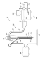
- FIG. 1 is a configuration diagram of the endoscope system 1 of the present embodiment.
- the endoscope system 1 includes a processor 100, a scope 200, a monitor 300, a high-frequency treatment instrument 400, and a high-frequency power source 500.
- the scope 200 has an insertion portion 21 to be inserted into a patient's lumen, an operation portion 23 operated by an operator, a universal tube 25 extending from the operation portion 23, and a connector portion 27 detachably connected to the processor 100. is doing.
- a light guide that extends from the connector portion 27 to the distal end portion 21a of the insertion portion 21 and guides the irradiation light irradiated to the subject is disposed. In FIG. 1, the light guide is not shown.
- the processor 100 includes various electronic circuits for controlling the operation of the endoscope system 1, a light source unit that emits illumination light for illuminating a subject, and an operation panel that receives an operation by an operator.
- the electronic circuit, the light source unit, and the operation panel are not shown.
- the operation panel is used to change parameters relating to the operation of the endoscope system 1.
- Illumination light emitted from the light source unit enters the scope 200 via the connector unit 27.
- Illumination light incident on the scope 200 from the processor 100 is guided through the light guide, emitted from the distal end portion 21a of the insertion portion 21, and irradiated on the subject.
- the insertion portion 21 of the scope 200 has a long rod shape, and the distal end portion 21a is curved in response to an operation on the operation portion 23.
- the portions other than the distal end portion 21a of the insertion portion 21 are flexible.
- the insertion portion 21 has a surface covered with a protective tube 21b in order to protect internal wiring and structure and prevent liquid and dirt from entering the inside.
- the protective tube 21b is formed of a soft material such as a thin resin so that the flexibility of the insertion portion 21 is not impaired.
- the surgeon inserts the insertion portion 21 into the patient's lumen while bending the insertion portion 21.
- An imaging element (not shown) for imaging a subject in the lumen is provided at the distal end 21a of the insertion unit 21.
- An imaging signal of the subject imaged by the imaging element is input to the processor 100 via the connector unit 27.
- the processor 100 performs predetermined signal processing on the imaging signal of the subject input from the scope 200 to generate a video signal. By outputting this video signal to the monitor 300, a photographed image of the subject is displayed on the monitor 300.
- the scope 200 has a treatment instrument channel 29 through which various treatment instruments are inserted.
- the treatment instrument channel 29 is disposed in the insertion portion 21, one end is provided near the operation portion 23, and the other end is provided at the distal end portion 21 a of the insertion portion 21.
- the surgeon inserts the treatment instrument into the treatment instrument channel 29 from the operation unit 23 side and protrudes from the distal end 21 a of the insertion part 21.
- the surgeon can operate the treatment tool while viewing the captured image displayed on the monitor 300 to treat the affected part in the lumen.
- a high-frequency treatment instrument 400 is used as the treatment instrument inserted into the treatment instrument channel 29.
- the high-frequency treatment instrument 400 is connected to a high-frequency power source 500 that supplies a high-frequency current.
- the high-frequency treatment tool 400 is energized when a high-frequency current is supplied, and is used for performing treatment such as incision or coagulation of the affected part.
- the high-frequency treatment instrument 400 is roughly classified into a monopolar type such as a high-frequency knife and a bipolar type such as a high-frequency forceps.
- a high-frequency treatment instrument 400 shown in FIG. 1 is a monopolar type high-frequency treatment instrument 400.
- a patient counter electrode 41 is attached to the outer skin of the patient.
- the patient counter electrode 41 is connected to a high frequency power source 500.
- the high-frequency treatment tool 400 touches the body tissue in the lumen of the patient, the current supplied to the high-frequency treatment tool 400 flows to the patient counter electrode plate 41 through the patient's body. As the high-frequency current flows in this manner, Joule heat is generated and the affected area can be treated.
- the high-frequency forceps has two clamping parts that sandwich the affected part. Each of the two clamping portions is independently connected to the high frequency power source 500.
- the high-frequency current flows from one of the two clamping parts to the other through the affected part. Thereby, the treatment of the affected part pinched by the clamping part can be performed.
- the patient counter electrode 41 is not used.
- the high-frequency treatment instrument 400 When the monopolar type or the bipolar type is used as the high-frequency treatment instrument 400, it is common in that the high-frequency treatment instrument 400 generates Joule heat by a high-frequency current.
- electromagnetic noise may be generated from the high frequency treatment instrument 400.
- This electromagnetic noise can generate an induced current in the imaging element, the wiring connected thereto, the electronic circuit, the metal member 21c used for the insertion portion 21 of the scope 200, and the like that is close to the treatment instrument channel 29. There is sex.
- an induced current When an induced current is generated in the image sensor, wiring connected to the image sensor, and electronic circuit, noise may occur in a captured image of the subject.
- the insertion portion 21 is covered with a protective tube 21b that does not conduct electricity, and is configured so that the operator does not directly touch the metal member 21c.
- the metal member 21c is grounded via the processor 100 in order to more reliably prevent the surgeon from receiving an electric shock.
- the metal member 21 c is connected to the frame ground FG of the processor 100.
- the frame ground FG is, for example, a member formed of metal in the housing or chassis of the processor 100.
- the metal member 21 c has a long tube shape along the longitudinal direction of the insertion portion 21.
- the metal member 21c is disposed so as to cover the light guide and the treatment instrument channel 29, and protects them.
- a metal spiral tube is used for the metal member 21c.
- a metal spiral tube is a thin metal plate formed in a coil shape, and has flexibility. Therefore, even if the metal member 21c is disposed in the insertion portion 21, the insertion portion 21 can be flexible.
- the metal member 21 c is connected to a plate-like metal base material 23 c provided in the operation unit 23.
- the metal base material 23 c is used for supporting a bending operation knob (not shown) in the operation unit 23.
- the metal substrate 23c and the metal member 21c are electrically connected to each other and can be energized with each other.
- the metal substrate 23c and the connector part 27 are connected by a return wiring 31.
- the feedback wiring 31 is disposed from the operation unit 23 of the scope 200 to the universal cable 25, and is used to release the induced current generated in the metal member 21c to the frame ground FG.
- the feedback wiring 31 is connected to the relay wiring 33 in the processor 100 via the connector unit 27.
- the relay wiring 33 connects the feedback wiring 31 and the feedback terminal 35 provided on the exterior surface of the processor 100.
- a capacitor box 37 having a capacitor inside is disposed outside the processor 100.
- Two wirings 37 a and 37 b extend from the capacitor box 37, and the two wirings 37 a and 37 b are respectively connected to both ends of the capacitor in the capacitor box 37.
- the two wirings 37 a and 37 b extending from the capacitor box 37 are detachably connected to a feedback terminal 35 and a ground terminal 39 provided on the exterior surface of the processor 100, respectively.
- the ground terminal 39 is connected to the frame ground FG of the processor 100.
- the metal member 21 c of the insertion portion 21 is connected to the frame ground FG via the metal base 23 c of the operation portion 23, the return wiring 31, the relay wiring 33, and the capacitor box 37.
- the capacitor in the capacitor box 37 usually has a characteristic of passing an AC component of current. Therefore, by grounding the metal member 21c via the capacitor box 37 (AC coupling of the metal member 21c to the frame ground FG), high-frequency induced current generated in the metal member 21c is efficiently supplied to the frame ground FG. I can escape.
- the optimum capacity of the capacitor for allowing the induced current to escape to the frame ground FG and the electric circuit configuration of the capacitor box 37 differ depending on the frequency of the induced current. Therefore, by exchanging the capacitor box 37 connected to the processor 100 according to the high-frequency treatment instrument 400 or the high-frequency power source 500 to be used, the induced current can be more reliably released to the frame ground FG.
- the capacitor box 37 can be attached to and detached from the processor 100 (the feedback terminal 35 and the ground terminal 39), so that the capacitor box 37 can be easily replaced.
- the return wiring 31 is arranged in the scope 200 and is connected to the processor 100 via the connector unit 27. Therefore, unlike the prior art, the scope 200 of this embodiment does not need to be provided with a feedback terminal separately from the connector portion 27. Thereby, the protrusion by a feedback terminal can be reduced from the exterior of the scope 200.
- the insertion portion 21 can be prevented from coming into contact with the protrusions.
- the insertion part 21 is covered with a protective tube 21b made of a soft material. Therefore, by suppressing the contact between the insertion portion 21 and the protrusion, it is possible to suppress the soft protective tube 21b from being damaged due to the contact with the protrusion.
- the scope is provided with a connector portion and a feedback terminal separately. Therefore, in order to make the scope usable, it is necessary to separately perform the connection operation of the connector unit to the processor and the connection operation of the wiring to the feedback terminal.
- the connection portion of the feedback wiring 31 with the processor 100 (relay wiring 33) is arranged in the connector portion 27. Therefore, the feedback wiring 31 is connected to the relay wiring 33 by performing the connection operation of the connector unit 27 to the processor 100. Therefore, in this embodiment, the operation for enabling the scope 200 is easy, and it is possible to prevent the feedback wiring 31 from being forgotten to be grounded.
- the feedback wiring 31 is arranged from the connector portion 27 of the scope 200 to the operation portion 23, but the present invention is not limited to this configuration.
- the return wiring 31 may be connected to the metal member 21 c of the insertion portion 21.
- the metal member used in the insertion portion 21 is not limited to the coiled metal member 21c.
- the insertion part 21 may be disposed so as to cover the metal member 21c, for example, and may have a metal mesh formed in a tube shape.
- the metal mesh is used to shield electromagnetic noise radiated from the inside of the insertion portion 21 to the outside and electromagnetic noise entering the inside from the outside of the insertion portion 21.
- the metal mesh or both the metal mesh and the metal member 21c are connected to the metal base material 23c.
- the capacitor box 37 is connected to the processor 100 when the high frequency treatment instrument 400 is used as a treatment instrument. Therefore, the capacitor box 37 may be removed from the processor 100 when using a treatment instrument that does not need to supply a high-frequency current.
- Embodiments of the present invention are not limited to those described above, and various modifications are possible within the scope of the technical idea of the present invention.
- the embodiment of the present invention also includes contents appropriately combined with embodiments or the like clearly shown in the specification or obvious embodiments.
Landscapes
- Health & Medical Sciences (AREA)
- Life Sciences & Earth Sciences (AREA)
- Surgery (AREA)
- Engineering & Computer Science (AREA)
- General Health & Medical Sciences (AREA)
- Veterinary Medicine (AREA)
- Public Health (AREA)
- Physics & Mathematics (AREA)
- Nuclear Medicine, Radiotherapy & Molecular Imaging (AREA)
- Animal Behavior & Ethology (AREA)
- Biomedical Technology (AREA)
- Heart & Thoracic Surgery (AREA)
- Medical Informatics (AREA)
- Molecular Biology (AREA)
- Biophysics (AREA)
- Radiology & Medical Imaging (AREA)
- Pathology (AREA)
- Optics & Photonics (AREA)
- Plasma & Fusion (AREA)
- Otolaryngology (AREA)
- Endoscopes (AREA)
- Instruments For Viewing The Inside Of Hollow Bodies (AREA)
- Surgical Instruments (AREA)
Abstract
内視鏡システムを、筐体の外装面上に設けられた接地端子と、外装面上に設けられており、筐体の外部に配置された外部コンデンサを介して接地端子と接続される帰還端子と、帰還端子と接続され、筐体内に配置された中継配線と、を有するプロセッサと、プロセッサに対して着脱可能なコネクタ部と、処置具が挿入されるチャネルと、チャネルに近接する位置の金属部材をコネクタ部と接続する帰還配線と、を有するスコープとから構成する。この構成において、コネクタ部がプロセッサに装着されると、帰還配線と中継配線とが接続され、これにより、金属部材が帰還配線、中継配線、帰還端子及び外部コンデンサを介して接地端子と接続される。
Description
本発明は、内視鏡システムに関する。
人の食道や腸などの管腔内にスコープを挿入し、管腔内を観察しながら処置を行う内視鏡システムが知られている。この種の内視鏡システムでは、鉗子やメス等の処置具をスコープ内に通し、スコープの先端部から突出させることにより、管腔内の患部の処置が行われる。使用する処置具としては、患部の切除や止血を行うための高周波処置具が知られている。
このような内視鏡システムとして、例えば、特開2007-202654号公報(以下、「特許文献1」と記す。)に、高周波メスを使用する内視鏡システムが開示されている。高周波メスのような高周波処置具を使用する場合、高周波処置具で発生した電磁波によってスコープの金属部材内に誘導電流が流れる場合がある。この誘導電流は、被写体の撮影画像にノイズとして表れる。そのため、特許文献1に記載の内視鏡システムでは、誘導電流を逃がすために、スコープに帰還端子を設けている。この帰還端子を、例えば、プロセッサのアースに接続することにより、金属部材内に流れた電流がアースへ逃がされる。なお、金属部材内に流れる電流は高周波成分を有しているため、帰還端子とアースとの間には、通常、アースへの直接接続の代わりに高周波電流をアースへ逃がすためのコンデンサが配置される。
特許文献1に記載の電子内視鏡システムでは、スコープの外装面上に帰還端子が設けられている。そのため、使用済みのスコープを洗浄する場合や、スコープを搬送する場合に、スコープの管腔内への挿入部が帰還端子に接触する場合があった。挿入部は内部の配線等の保護のため、保護チューブで覆われている。この保護チューブには、挿入部が湾曲しやすいように、薄く形成された樹脂などの柔らかい材料が使用されている。そのため、挿入部が帰還端子に接触すると、保護チューブが損傷する虞があった。
本発明は上記の事情に鑑みてなされたものであり、その目的とするところは、スコープの損傷を抑制するのに好適な内視鏡システムを提供することである。
本発明の一実施形態に係る内視鏡システムは、筐体の外装面上に設けられた接地端子と、外装面上に設けられており、筐体の外部に配置された外部コンデンサを介して接地端子と接続される帰還端子と、帰還端子と接続され、筐体内に配置された中継配線と、を有するプロセッサと、プロセッサに対して着脱可能なコネクタ部と、処置具が挿入されるチャネルと、チャネルに近接する位置の金属部材をコネクタ部と接続する帰還配線と、を有するスコープとから構成される。この構成において、コネクタ部がプロセッサに装着されると、帰還配線と中継配線とが接続され、これにより、金属部材が帰還配線、中継配線、帰還端子及び外部コンデンサを介して接地端子と接続される。
本発明の一実施形態によれば、例えば、スコープが、コネクタ部を介してプロセッサに接続されると、スコープ内の金属部材は、帰還配線、中継配線、コンデンサを介して接地される。そのため、スコープには、コネクタ部とは別に、金属部材を設置するための配線を接続する端子を設ける必要がなくなる。これにより、スコープが端子と接触して損傷することを抑制できる。
また、本発明の一実施形態において、スコープは、例えば、可撓性を有する棒形状の挿入部であって、患者の管腔内に挿入されるものを有する。この場合、金属部材は、挿入部内に配置され、挿入部の長手方向に沿って長尺なチューブ形状を有する。
また、本発明の一実施形態において、外部コンデンサは、例えば、接地端子及び帰還端子に着脱可能に接続される。
このような構成によれば、使用する高周波処置具や高周波電源に応じて、使用するコンデンサを容易に交換することができる。
本発明の実施形態によれば、スコープの損傷を抑制するのに好適な内視鏡システムが提供される。
以下、本発明の実施形態に係る内視鏡システムについて、図面を参照しながら説明する。
図1は、本実施形態の内視鏡システム1の構成図である。内視鏡システム1は、プロセッサ100、スコープ200、モニタ300、高周波処置具400、高周波電源500を有している。
スコープ200は、患者の管腔内に挿入される挿入部21、術者によって操作される操作部23、操作部23から延びるユニバーサルチューブ25、プロセッサ100に着脱可能に接続されるコネクタ部27を有している。また、スコープ200内には、コネクタ部27から挿入部21の先端部21aまで伸び、被写体に照射される照射光を導光するライトガイドが配置されている。図1では、ライトガイドの図示は省略されている。
プロセッサ100は、内視鏡システム1の動作を制御するための各種電子回路、被写体を照明する照明光を放射する光源ユニット、術者による操作を受け付ける操作パネルを有している。なお、図1では、これらの電子回路、光源ユニット、操作パネルの図示は省略されている。操作パネルは、内視鏡システム1の動作に関するパラメータを変更するために使用される。光源ユニットから放射された照明光は、コネクタ部27を介してスコープ200に入射される。プロセッサ100からスコープ200に入射された照明光は、ライトガイド内を導光されて挿入部21の先端部21aから放射され、被写体に照射される。
スコープ200の挿入部21は、長尺な棒形状を有しており、その先端部21aは、操作部23に対する操作に応じて湾曲する。挿入部21の先端部21a以外の箇所は可撓性を有している。また、挿入部21は、内部の配線や構造を保護し、且つ、内部への液体や汚れの侵入を防止するため、表面が保護チューブ21bで被覆されている。保護チューブ21bは、挿入部21の可撓性が損なわれないように、薄く形成された樹脂などの柔らかい材料で形成されている。術者は、挿入部21を湾曲させながら患者の管腔内へ挿入する。挿入部21の先端部21aには、管腔内の被写体を撮像するための撮像素子(不図示)が設けられている。撮像素子によって撮像された被写体の撮像信号は、コネクタ部27を介して、プロセッサ100に入力される。
プロセッサ100は、スコープ200から入力された被写体の撮像信号に対して所定の信号処理を施し、映像信号を生成する。この映像信号がモニタ300に出力されることにより、モニタ300には、被写体の撮影画像が表示される。
スコープ200は、各種処置具が挿通される処置具チャネル29を有している。処置具チャネル29は、挿入部21内に配置され、一端は操作部23付近に設けられ、他端は挿入部21の先端部21aに設けられている。術者は、操作部23側から処置具を処置具チャネル29に挿入し、挿入部21の先端部21aから突出させる。これにより、術者は、モニタ300に表示される撮影画像を見ながら処置具を操作し、管腔内の患部の処置を行うことができる。
処置具チャネル29に挿通される処置具には、例えば、高周波処置具400が使用される。高周波処置具400は、高周波電流を供給する高周波電源500と接続されている。高周波処置具400は、高周波電流が供給されることによって通電され、患部の切開や凝固などの処置を行うために使用される。
高周波処置具400は、高周波メスなどのモノポーラタイプと、高周波鉗子などのバイポーラタイプに大別される。図1に示される高周波処置具400は、モノポーラタイプの高周波処置具400である。モノポーラタイプの高周波処置具400を使用する場合、患者の外皮に患者対極板41が貼り付けられる。患者対極板41は、高周波電源500と接続されている。高周波処置具400が患者の管腔内の体組織に触れると、高周波処置具400に供給されている電流が、患者の体を介して患者対極板41に流れる。このように高周波電流が流れることにより、ジュール熱が発生し、患部の処置を行うことができる。
次に、バイポーラタイプの高周波処置具400として、例えば、高周波鉗子を使用する場合について説明する。高周波鉗子は、患部を挟む2つの挟持部を有している。この2つの挟持部はそれぞれ、独立して高周波電源500と接続されている。高周波鉗子に高周波電流が供給されている状態で2つの挟持部によって患部が挟まれると、2つの挟持部の一方から他方へ、患部を介して高周波電流が流れる。これにより、挟持部によって挟まれた患部の処置を行うことができる。なお、バイポーラタイプの高周波処置具400を使用する場合は、患者対極板41は使用されない。
高周波処置具400として、モノポーラタイプとバイポーラタイプの何れのタイプを使用する場合においても、高周波電流によって高周波処置具400がジュール熱を発生するという点で共通する。高周波処置具400がジュール熱を発生すると、高周波処置具400から電磁ノイズが発生する場合がある。この電磁ノイズは、撮像素子及びそれに接続される配線、電子回路や、スコープ200の挿入部21に使用される金属部材21cなどのうち、処置具チャネル29に近接するものに誘導電流を発生させる可能性がある。撮像素子及びそれに接続される配線、電子回路に誘導電流が発生すると、被写体の撮影画像にノイズが発生する虞がある。また、スコープ200の挿入部21に使用される金属部材21cに誘導電流が発生すると、術者がその金属部材21cに接触した時に、感電してしまう虞がある。そのため、挿入部21は、電気を通さない保護チューブ21bで被覆され、術者が金属部材21cに直接触れないように構成されている。更に、術者が感電してしまうことをより確実に防止するため、金属部材21cは、プロセッサ100を介して接地されている。詳しくは、金属部材21cは、プロセッサ100のフレームグラウンドFGに接続されている。フレームグラウンドFGは、例えば、プロセッサ100の筐体やシャーシ等の内、金属によって形成された部材である。
次に、本実施形態における、挿入部21の金属部材21cを接地する構成について説明する。金属部材21cは、挿入部21の長手方向に沿って長尺なチューブ形状を有している。金属部材21cは、ライトガイドや処置具チャネル29を覆うように配置されており、これらを保護している。また、この金属部材21cには、例えば、金属製のスパイラルチューブが使用される。金属製のスパイラルチューブは、薄い金属板をコイル状に形成したものであり、可撓性を有している。そのため、金属部材21cを挿入部21内に配置したとしても、挿入部21に可撓性を持たせることができる。金属部材21cは、操作部23内に設けられた板状の金属基材23cと接続されている。金属基材23cは、操作部23における湾曲操作ノブ(不図示)等の支持に用いられる。金属基材23cと金属部材21cとは互いに電気的に接続されており、互いに通電可能である。
金属基材23cとコネクタ部27は、帰還配線31で接続されている。帰還配線31は、スコープ200の操作部23内からユニバーサルケーブル25内に亘って配置されており、金属部材21cに発生した誘導電流をフレームグランドFGに逃がすために使用される。スコープ200がプロセッサ100に接続されると、帰還配線31は、コネクタ部27を介して、プロセッサ100内の中継配線33に接続される。スコープ200がプロセッサ100に接続された状態において、中継配線33は、帰還配線31とプロセッサ100の外装面上に設けられた帰還端子35とを接続する。
プロセッサ100の外側には、内部にコンデンサを備えるコンデンサボックス37が配置されている。コンデンサボックス37からは、2つの配線37a、37bが伸びており、2つの配線37a、37bはそれぞれ、コンデンサボックス37内でコンデンサの両端に接続される。また、コンデンサボックス37から延びた2つの配線37a、37bはそれぞれ、プロセッサ100の外装面に設けられた帰還端子35及び接地端子39に着脱可能に接続される。接地端子39は、プロセッサ100のフレームグラウンドFGに接続されている。
スコープ200及びコンデンサボックス37がプロセッサ100に接続されると、挿入部21の金属部材21cは、操作部23の金属基材23c、帰還配線31、中継配線33、コンデンサボックス37を介してフレームグラウンドFGに接続される。コンデンサボックス37内のコンデンサは、通常、電流の交流成分を通す特性を有する。そのため、金属部材21cを、コンデンサボックス37を介して接地する(金属部材21cを、フレームグランドFGにAC結合する)ことにより、金属部材21cに発生した高周波の誘導電流を効率的にフレームグランドFGへ逃がすことができる。
なお、誘導電流をフレームグランドFGへ逃がすためのコンデンサの最適な容量やコンデンサボックス37の電気回路構成は、誘導電流の周波数に応じて異なる。そのため、使用する高周波処置具400や高周波電源500に応じて、プロセッサ100に接続するコンデンサボックス37を交換することにより、より確実に誘導電流をフレームグランドFGへ逃がすことができる。また、本実施形態では、コンデンサボックス37は、プロセッサ100(帰還端子35、接地端子39)に対して着脱可能であるため、コンデンサボックス37の交換が容易である。
本実施形態では、帰還配線31はスコープ200内に配置されており、コネクタ部27を介してプロセッサ100に接続される。そのため、従来技術とは異なり、本実施形態のスコープ200には、コネクタ部27とは別に帰還端子を設ける必要がない。これにより、スコープ200の外装から帰還端子による突起を減らすことできる。スコープ200の外装から突起が減ることにより、例えば、スコープ200を洗浄する際や搬送する際に、挿入部21が突起と接触することを抑制することができる。挿入部21は、柔らかい材料で形成された保護チューブ21bで被覆されている。そのため、挿入部21と突起との接触を抑制することにより、柔らかい保護チューブ21bが突起との接触により損傷してしまうことを抑制することができる。
また、従来技術では、スコープには、コネクタ部と帰還端子とが別々に設けられていた。そのため、スコープを使用可能な状態とするためには、コネクタ部のプロセッサへの接続操作と、帰還端子への配線の接続操作を別々に行う必要があった。これに対し、本実施形態では、帰還配線31のプロセッサ100(中継配線33)との接続部分が、コネクタ部27に配置されている。そのため、コネクタ部27のプロセッサ100への接続操作を行うことによって、帰還配線31が中継配線33に接続される。従って、本実施形態では、スコープ200を使用可能とするための操作が容易であると共に、帰還配線31を接地し忘れてしまうことを防止できる。
なお、図1に示される構成では、帰還配線31は、スコープ200のコネクタ部27から操作部23に亘って配置されているが、本発明はこの構成に限定されない。例えば、帰還配線31は、挿入部21の金属部材21cに接続されてもよい。これにより、金属基材23cと金属部材21cとが接続されていなくても、確実に誘導電流をフレームグランドFGに流すことができる。
また、挿入部21で使用される金属部材は、コイル状の金属部材21cに限定されない。挿入部21は、例えば、金属部材21cを被覆するように配置され、チューブ状に形成された金属メッシュを有していてもよい。この金属メッシュは、挿入部21の内部から外部へ放射される電磁ノイズ、及び、挿入部21の外部から内部へ入り込む電磁ノイズを遮蔽するために使用される。この場合、金属メッシュ、又は、金属メッシュと金属部材21cの両方が、金属基材23cに接続される。
また、コンデンサボックス37は、処置具として高周波処置具400を使用する場合に、プロセッサ100に接続される。そのため、高周波電流を供給する必要のない処置具を使用する場合、コンデンサボックス37はプロセッサ100から取り外されてもよい。
以上が本発明の例示的な実施形態の説明である。本発明の実施形態は、上記に説明したものに限定されず、本発明の技術的思想の範囲において様々な変形が可能である。例えば明細書中に例示的に明示される実施形態等又は自明な実施形態等を適宜組み合わせた内容も本発明の実施形態に含まれる。
Claims (3)
- 筐体の外装面上に設けられた接地端子と、
前記外装面上に設けられており、前記筐体の外部に配置された外部コンデンサを介して前記接地端子と接続される帰還端子と、
前記帰還端子と接続され、前記筐体内に配置された中継配線と、
を有するプロセッサと、
前記プロセッサに対して着脱可能なコネクタ部と、
処置具が挿入されるチャネルと、
前記チャネルに近接する位置の金属部材を前記コネクタ部と接続する帰還配線と、
を有するスコープと、
を備え、
前記コネクタ部が前記プロセッサに装着されると、前記帰還配線と前記中継配線とが接続され、これにより、前記金属部材が該帰還配線、該中継配線、前記帰還端子及び前記外部コンデンサを介して前記接地端子と接続される、
内視鏡システム。 - 前記スコープは、可撓性を有する棒形状の挿入部であって、患者の管腔内に挿入されるものを有し、
前記金属部材は、前記挿入部内に配置され、該挿入部の長手方向に沿って長尺なチューブ形状を有する、
請求項1に記載の内視鏡システム。 - 前記外部コンデンサは、前記接地端子及び前記帰還端子に着脱可能に接続される、
請求項1又は請求項2に記載の内視鏡システム。
Priority Applications (3)
| Application Number | Priority Date | Filing Date | Title |
|---|---|---|---|
| US15/767,007 US20180289244A1 (en) | 2015-12-16 | 2016-12-02 | Endoscope system |
| DE112016004196.9T DE112016004196B4 (de) | 2015-12-16 | 2016-12-02 | Endoskopsystem |
| CN201690001316.5U CN208837874U (zh) | 2015-12-16 | 2016-12-02 | 内窥镜系统 |
Applications Claiming Priority (2)
| Application Number | Priority Date | Filing Date | Title |
|---|---|---|---|
| JP2015-244836 | 2015-12-16 | ||
| JP2015244836A JP6356656B2 (ja) | 2015-12-16 | 2015-12-16 | 内視鏡システム |
Publications (1)
| Publication Number | Publication Date |
|---|---|
| WO2017104441A1 true WO2017104441A1 (ja) | 2017-06-22 |
Family
ID=59056378
Family Applications (1)
| Application Number | Title | Priority Date | Filing Date |
|---|---|---|---|
| PCT/JP2016/085869 Ceased WO2017104441A1 (ja) | 2015-12-16 | 2016-12-02 | 内視鏡システム |
Country Status (5)
| Country | Link |
|---|---|
| US (1) | US20180289244A1 (ja) |
| JP (1) | JP6356656B2 (ja) |
| CN (1) | CN208837874U (ja) |
| DE (1) | DE112016004196B4 (ja) |
| WO (1) | WO2017104441A1 (ja) |
Families Citing this family (1)
| Publication number | Priority date | Publication date | Assignee | Title |
|---|---|---|---|---|
| US11605941B2 (en) * | 2020-08-28 | 2023-03-14 | Michael Corsi | Method and system for monitoring and regulating induced ground line power |
Citations (2)
| Publication number | Priority date | Publication date | Assignee | Title |
|---|---|---|---|---|
| JP2004130126A (ja) * | 2002-09-20 | 2004-04-30 | Pentax Corp | 電子内視鏡装置 |
| JP2014054318A (ja) * | 2012-09-11 | 2014-03-27 | Fujifilm Corp | 内視鏡システム、内視鏡、光源装置、及びプロセッサ |
Family Cites Families (1)
| Publication number | Priority date | Publication date | Assignee | Title |
|---|---|---|---|---|
| JP2007202654A (ja) | 2006-01-31 | 2007-08-16 | Olympus Medical Systems Corp | 医療装置 |
-
2015
- 2015-12-16 JP JP2015244836A patent/JP6356656B2/ja active Active
-
2016
- 2016-12-02 WO PCT/JP2016/085869 patent/WO2017104441A1/ja not_active Ceased
- 2016-12-02 CN CN201690001316.5U patent/CN208837874U/zh active Active
- 2016-12-02 DE DE112016004196.9T patent/DE112016004196B4/de active Active
- 2016-12-02 US US15/767,007 patent/US20180289244A1/en not_active Abandoned
Patent Citations (2)
| Publication number | Priority date | Publication date | Assignee | Title |
|---|---|---|---|---|
| JP2004130126A (ja) * | 2002-09-20 | 2004-04-30 | Pentax Corp | 電子内視鏡装置 |
| JP2014054318A (ja) * | 2012-09-11 | 2014-03-27 | Fujifilm Corp | 内視鏡システム、内視鏡、光源装置、及びプロセッサ |
Also Published As
| Publication number | Publication date |
|---|---|
| DE112016004196T5 (de) | 2018-06-07 |
| CN208837874U (zh) | 2019-05-10 |
| DE112016004196B4 (de) | 2019-07-11 |
| JP2017108874A (ja) | 2017-06-22 |
| JP6356656B2 (ja) | 2018-07-11 |
| US20180289244A1 (en) | 2018-10-11 |
Similar Documents
| Publication | Publication Date | Title |
|---|---|---|
| US4607621A (en) | Endoscopic apparatus | |
| CN109414250B (zh) | 超声波内窥镜 | |
| US8187175B2 (en) | Endoscope, endoscope apparatus, and method of connecting external equipment to endoscope | |
| EP3125740B1 (en) | Medical system and related methods for diagnosis and treatment | |
| US10070778B2 (en) | Endoscope system, endoscope, and endoscope connector | |
| JPWO2018221672A1 (ja) | 単回使用内視鏡装置 | |
| JP4390511B2 (ja) | 電子内視鏡装置 | |
| JP2016214662A (ja) | 医療用カメラヘッド及び医療用カメラ装置 | |
| CN112822969B (zh) | 用于一次性输尿管镜的按钮适配器 | |
| JP2014054318A (ja) | 内視鏡システム、内視鏡、光源装置、及びプロセッサ | |
| CN107530056B (zh) | 内窥镜用连接器 | |
| JP6356656B2 (ja) | 内視鏡システム | |
| CN109414253B (zh) | 超声波内窥镜 | |
| JP5836505B2 (ja) | 内視鏡用アダプタ及び内視鏡 | |
| JP6602580B2 (ja) | 内視鏡システム | |
| KR101652417B1 (ko) | 복강경 장치 | |
| CN103781399B (zh) | 内窥镜的光源用电源装置 | |
| JP2007289674A (ja) | 肺癌治療カテーテル | |
| JP2000245734A (ja) | 超音波内視鏡診断装置 | |
| WO2014010283A1 (ja) | 超音波内視鏡 | |
| JP3091211B2 (ja) | 内視鏡装置 | |
| JP2001061855A (ja) | 内視鏡用焼灼装置 | |
| JP7233933B2 (ja) | 電子内視鏡及び電子内視鏡システム | |
| JP3250790B2 (ja) | 内視鏡 | |
| JP2010063529A (ja) | 電子内視鏡及び内視鏡システム |
Legal Events
| Date | Code | Title | Description |
|---|---|---|---|
| 121 | Ep: the epo has been informed by wipo that ep was designated in this application |
Ref document number: 16875424 Country of ref document: EP Kind code of ref document: A1 |
|
| WWE | Wipo information: entry into national phase |
Ref document number: 15767007 Country of ref document: US |
|
| WWE | Wipo information: entry into national phase |
Ref document number: 112016004196 Country of ref document: DE |
|
| 122 | Ep: pct application non-entry in european phase |
Ref document number: 16875424 Country of ref document: EP Kind code of ref document: A1 |