WO2017104356A1 - 液冷式圧縮機及びその運転方法 - Google Patents
液冷式圧縮機及びその運転方法 Download PDFInfo
- Publication number
- WO2017104356A1 WO2017104356A1 PCT/JP2016/084503 JP2016084503W WO2017104356A1 WO 2017104356 A1 WO2017104356 A1 WO 2017104356A1 JP 2016084503 W JP2016084503 W JP 2016084503W WO 2017104356 A1 WO2017104356 A1 WO 2017104356A1
- Authority
- WO
- WIPO (PCT)
- Prior art keywords
- flow path
- suction
- valve
- compressor
- pressure
- Prior art date
- Legal status (The legal status is an assumption and is not a legal conclusion. Google has not performed a legal analysis and makes no representation as to the accuracy of the status listed.)
- Ceased
Links
Images




Classifications
-
- F—MECHANICAL ENGINEERING; LIGHTING; HEATING; WEAPONS; BLASTING
- F04—POSITIVE - DISPLACEMENT MACHINES FOR LIQUIDS; PUMPS FOR LIQUIDS OR ELASTIC FLUIDS
- F04B—POSITIVE-DISPLACEMENT MACHINES FOR LIQUIDS; PUMPS
- F04B39/00—Component parts, details, or accessories, of pumps or pumping systems specially adapted for elastic fluids, not otherwise provided for in, or of interest apart from, groups F04B25/00 - F04B37/00
- F04B39/10—Adaptations or arrangements of distribution members
-
- F—MECHANICAL ENGINEERING; LIGHTING; HEATING; WEAPONS; BLASTING
- F04—POSITIVE - DISPLACEMENT MACHINES FOR LIQUIDS; PUMPS FOR LIQUIDS OR ELASTIC FLUIDS
- F04B—POSITIVE-DISPLACEMENT MACHINES FOR LIQUIDS; PUMPS
- F04B49/00—Control, e.g. of pump delivery, or pump pressure of, or safety measures for, machines, pumps, or pumping installations, not otherwise provided for, or of interest apart from, groups F04B1/00 - F04B47/00
- F04B49/02—Stopping, starting, unloading or idling control
- F04B49/03—Stopping, starting, unloading or idling control by means of valves
-
- F—MECHANICAL ENGINEERING; LIGHTING; HEATING; WEAPONS; BLASTING
- F04—POSITIVE - DISPLACEMENT MACHINES FOR LIQUIDS; PUMPS FOR LIQUIDS OR ELASTIC FLUIDS
- F04C—ROTARY-PISTON, OR OSCILLATING-PISTON, POSITIVE-DISPLACEMENT MACHINES FOR LIQUIDS; ROTARY-PISTON, OR OSCILLATING-PISTON, POSITIVE-DISPLACEMENT PUMPS
- F04C28/00—Control of, monitoring of, or safety arrangements for, pumps or pumping installations specially adapted for elastic fluids
- F04C28/06—Control of, monitoring of, or safety arrangements for, pumps or pumping installations specially adapted for elastic fluids specially adapted for stopping, starting, idling or no-load operation
Definitions
- the present invention relates to a liquid-cooled compressor and an operation method thereof.
- the discharge capacity is adjusted by switching between no-load operation and load operation. Yes.
- the suction adjustment valve is closed and the operation proceeds to a no-load operation that opens the air release flow path.
- the suction adjustment valve is opened and the air release flow path is closed.
- Patent Document 1 is known as a conventional technique for avoiding damage to a liquid-cooled compressor.
- Patent Document 1 discloses that a return passage and a relief passage are formed at a tip portion of a discharge path during no-load operation that guides compressed air from a discharge port to a suction valve during no-load operation.
- the return passage communicates with the downstream side of the intake valve, and the escape passage communicates with the upstream side of the intake valve.
- a throttle portion that restricts the flow of compressed air is provided in the middle of the return passage.
- the technical problem to be solved by the present invention is to reliably avoid that the pressure in the gas compression space becomes an undesired negative pressure when the suction regulating valve is closed in the liquid-cooled compressor. It is possible to prevent noise when the suction adjustment valve is opened.
- the following liquid-cooled compressor is provided.
- the liquid-cooled compressor of the present invention is branched from the compressor main body disposed between the suction flow path and the discharge flow path, the suction adjustment valve provided in the suction flow path, and the discharge flow path.
- a return flow path connected to the suction flow path located between the suction adjustment valve and the compressor body, an open / close valve provided in the return flow path, and a downstream side of the open / close valve An air release flow path branched in the return flow path, and a throttle provided in the air release flow path, on the main body suction side of the suction flow path when the suction adjustment valve is closed It is comprised so that the main body side suction pressure may exceed the lower limit negative pressure which avoids the plosive sound from the said suction adjustment valve.
- the main body side suction pressure when the suction adjustment valve is closed is configured to exceed the lower limit negative pressure by the throttle portion provided in the atmosphere open flow path branched from the return flow path. Yes. Therefore, a large plosive noise caused by an undesired negative pressure when the suction regulating valve is opened can be avoided and noise can be prevented.
- the liquid-cooled compressor of the present invention also includes a compressor body disposed between the suction flow path and the discharge flow path, a suction adjustment valve that is provided in the suction flow path and into which the compressed gas is introduced, A return flow path branched from the discharge flow path and connected to the suction flow path located on the downstream side of the suction adjustment valve on the downstream side, provided in the return flow path, and for closing the suction adjustment valve An opening / closing valve that is opened along with the opening, an atmosphere opening passage that branches off in the return passage located downstream of the opening / closing valve, and a restriction provided in the atmosphere opening passage. Is provided with a flow path for maintaining the pressure on the return flow path side of the open air flow path at a predetermined positive pressure higher than atmospheric pressure when the suction regulating valve is closed.
- the constriction provided in the open air flow path branched from the return flow path causes the pressure on the return flow path side of the open air flow path to be higher than the atmospheric pressure when the suction adjustment valve is closed.
- a flow path for maintaining a predetermined positive pressure is provided. Therefore, the throttle part can be adjusted in advance so as not to have a negative pressure (undesired negative pressure) that causes a loud plosive sound when the suction adjustment valve is opened.
- the present invention can have the following features in addition to the above features.
- a liquid separation / recovery device is provided on the discharge side of the main body of the discharge flow channel, and the discharge flow channel located downstream of the liquid separation / recovery device is branched into the return flow channel or the valve control flow channel.
- the compressed gas for example, air
- the configuration is simplified compared to the case where separate flow paths for supplying compressed gas (air) are provided.
- a compressor main body disposed between the suction flow path and the discharge flow path; a suction adjustment valve provided in the suction flow path; and a branch from the discharge flow path, and the suction adjustment valve and the compressor main body
- a return flow path connected to the suction flow path positioned in between, an on-off valve provided in the return flow path, and an open air flow path branched in the return flow path located downstream of the open / close valve
- a throttle part provided in the atmosphere opening flow path, wherein the suction adjustment valve is closed and the on-off valve is opened, and the discharge flow path
- the compressed gas flowing through the suction flow is returned to the suction flow channel via the return flow channel and partially opened to the atmosphere via the atmospheric flow flow channel, and the suction flow when the suction adjustment valve is closed
- the main body side suction pressure on the main body suction side of the road It is operated to exceed the lower limit negative pressure to avoid pop when opened valve.
- the main body side suction pressure when the suction adjustment valve is closed is operated so as to exceed the lower limit negative pressure, when the suction adjustment valve is opened, which is caused by an undesirable negative pressure.
- the plosive sound is avoided and noise can be prevented.
- a compressor body disposed between the suction flow path and the discharge flow path, a suction adjustment valve provided in the suction flow path and into which the compressed gas is introduced, branched from the discharge flow path, and on the downstream side Branching in the return flow path connected to the suction flow path located on the secondary side of the suction adjustment valve, the open / close valve provided in the return flow path, and the return flow path located downstream of the open / close valve
- a liquid-cooled compressor operating method comprising: an air release flow path; and a throttle provided in the air release flow path, wherein the suction adjustment valve is closed and the on-off valve is opened.
- the present invention it is possible to prevent the noise when the suction adjustment valve is opened, which is caused by the negative pressure of the main body side suction pressure when the suction adjustment valve is closed.
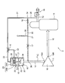
- the figure which shows schematic structure of the liquid cooling type compressor which concerns on 1st Embodiment of this invention The figure explaining the change of the suction adjustment valve opening degree of the liquid cooling type compressor shown in FIG.
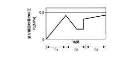
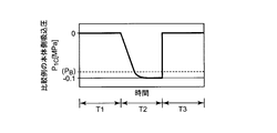
- the figure explaining the change of the main body side suction pressure of the liquid cooling compressor shown in FIG. The figure explaining the change of the internal pressure of the liquid separation recovery device of the liquid cooling compressor shown in FIG.
- the figure explaining the change of the supply pressure of the liquid cooling compressor shown in FIG. The figure explaining the change of the main body side suction pressure of the liquid cooling compressor which concerns on a comparative example.
- the figure which shows schematic structure of the liquid cooling type compressor which concerns on a comparative example The figure which shows schematic structure of the liquid cooling type compressor which concerns on 2nd Embodiment of this invention.
- the liquid-cooled compressor 1 according to the present invention will be described using an example in which an oil-cooled screw compressor 1 that uses oil as a coolant is used.
- the oil-cooled screw compressor 1 is simply referred to as a compressor 1.
- a compressor 1 and an operation method thereof according to a first embodiment of the present invention will be described with reference to FIGS. First, a schematic configuration of the compressor 1 will be described with reference to FIG.
- the compressor 1 includes a compressor main body 11, an oil separator / collector 13, an intake adjustment valve 20, a pressure holding unit 15, and an on-off valve 16.
- the compressor body 11 compresses a gas to be compressed, that is, a gas to be compressed (for example, air) by a pair of male and female screw rotors that mesh with each other.
- a gas to be compressed for example, air
- a pair of male and female screw rotors that mesh with each other is accommodated in a gas compression space (rotor chamber) 19 formed in a rotor casing.
- the compressor body 11 is disposed between the suction flow path 10 and the discharge flow path 12.
- the suction flow path 10 is connected to a suction port 19 ⁇ / b> A provided on the suction side of the rotor chamber 19 of the compressor body 11.
- the suction flow path 10 is a flow path that connects a suction filter (not shown) and the suction port 19 ⁇ / b> A, and a suction adjustment valve 20 is provided in the middle of the suction flow path 10.
- a discharge channel 12 is connected to a discharge port 19B provided on the discharge side of the rotor chamber 19.
- a liquid separation / recovery device (for example, an oil separation / recovery device) 13 is disposed in the discharge flow path 12.
- the compressed gas is discharged together with the cooling liquid, and is separated into the compressed gas and the cooling liquid by the liquid separation / recovery unit 13.
- the compressed gas from which the cooling liquid has been removed is discharged from the portion of the discharge flow path 12 connected to the upper portion of the liquid separation and recovery unit 13, passes through the pressure holding unit 15, and then supplied to the demand facility.
- the cooling liquid separated by the liquid separation / recovery unit 13 is temporarily stored in a liquid reservoir formed at the lower part of the liquid separation / recovery unit 13.
- the intake adjustment valve 20 includes a body 21, a valve body 24, a piston 28 coupled to the valve body 24 via a piston rod, and a spring 27.
- a flow path space 22 and a piston space 25 are provided inside the body 21.
- a pressurizing chamber 25A and a spring chamber 25B are formed.
- the flow path space 22 constitutes a part of the suction flow path 10 and is opened and closed by a valve body 24.
- the piston space 25 is partitioned from the flow path space 22 by a partition wall 29 and accommodates the piston 28 and the spring 27.
- the pressurizing chamber 25 ⁇ / b> A is a space for applying a pressure for moving the piston 28.
- the spring chamber 25B accommodates a spring 27 that biases the piston 28 toward the pressurizing chamber 25A, and communicates with the flow path space 22 through a gap between a through hole provided in the partition wall 29 and the piston rod. ing.
- a spring 27 is provided between the piston 28 and the partition wall 29, and is urged by the spring 27 so that the piston 28 is separated from the partition wall 29, that is, the valve body 24 closes the suction flow path 10. Therefore, when a pressure greater than the biasing force of the spring 27 is not applied to the pressure receiving surface of the piston 28 on the pressurizing chamber 25A side, the intake adjustment valve 20 is closed. This enables a substantially no-load operation at the start of startup (when the liquid separation / recovery unit 13 is at atmospheric pressure). On the other hand, when a pressing force larger than the biasing force of the spring 27 is applied to the pressure receiving surface of the piston 28 on the pressurizing chamber 25A side, the intake adjustment valve 20 is opened as shown in FIG. Allows load operation.
- the return flow path 35 branched from the discharge flow path 12 is further branched to the valve control flow path 31 along the way.
- the valve control flow path 31 is a flow path for controlling the opening and closing of the suction adjustment valve 20, and the valve opening flow path 33 that leads to the pressurizing chamber 25A and the valve closing flow path that leads to the spring chamber 25B by the three-way valve 18.
- Switching control of the three-way valve 18 is performed by a control unit (not shown). When the three-way valve 18 is controlled so that the valve opening flow path 33 communicates with the return flow path 35, the pressure of the compressed gas from the valve opening flow path 33 is applied to the piston 28.
- valve body 24 is pushed and moved so that the volume of the pressurizing chamber 25A is increased, and the intake adjustment valve 20 is opened.
- the three-way valve 18 is controlled so that the valve closing flow path 32 communicates with the valve opening flow path 33, the compressed gas from the valve opening flow path 33 flows into the spring chamber 25 ⁇ / b> B and the flow path space 22.
- the biasing force of the spring 27 is applied to the piston 28, so that the valve body 24 is pushed up and the intake adjustment valve 20 is closed.
- the return flow path 35 branched from the discharge flow path 12 is further branched to an atmosphere open flow path 36 at an open branch point 37.
- the open / close valve 16 is disposed in the return flow path 35 extending between the valve branch point 34 and the open branch point 37.
- the return flow path 35 is connected to the suction flow path 10 located on the secondary side of the intake adjustment valve 20.
- the return flow path 35 is connected to the suction flow path 10 at a suction merging point 38 located between the intake adjustment valve 20 and the compressor body 11.
- the air release channel 36 that communicates with the atmosphere is provided with a throttle portion 17 that regulates the flow rate of the compressed gas flowing through the air release channel 36.
- the throttle unit 17 regulates the flow rate of the compressed gas flowing through the open air flow path 36 to be smaller than the flow rate of the compressed gas flowing through the return flow path 35 from the open branch point 37 to the suction confluence point 38.
- the throttle unit 17 is, for example, an orifice, and may be a variable throttle valve or a flow rate adjustment valve. When a variable throttle valve or a flow rate adjustment valve is used as the throttle unit 17, fine adjustment for each apparatus can be easily performed.
- FIG. 2 is a diagram illustrating a change in the opening degree of the suction adjustment valve 20 in the compressor 1.
- Figure 3 is a diagram for explaining the changes of the body side inlet pressure P 1.
- Figure 4 is a diagram illustrating a change in the internal pressure P 2 of the liquid separator collector 13.
- Figure 5 is a diagram illustrating a change in the supply pressure P 3 of the compressor 1 is a pressure on the downstream side of the flow path of the holding pressure portion 15.
- the compressor main body 11 is started in a no-load operation state. After that, as shown in FIG. 2, the load adjustment operation is performed during T1 by opening the suction adjustment valve 20.
- the internal pressure P 2 of the liquid separator collector 13 over time increases. The compressed gas is held at the pressure holding unit 15 until it exceeds a predetermined pressure, and then supplied to the demand facility.
- the body-side suction pressure P 1 is over time once lowered.
- the pressure drop width of the body side inlet pressure P 1 is less restricted Is done. That is, in the atmosphere open flow path 36, a relatively small amount of compressed gas corresponding to the throttle rate of the throttle section 17 flows out to the atmosphere via the throttle section 17, and on the main body suction side of the suction flow path 10, a relative Large amount of compressed gas flows.
- the throttle rate in the throttle unit 17 in other words, setting the channel of the throttle unit 17
- the inside of the open channel 36 in other words, upstream of the throttle unit 17.
- the flow path of the throttle portion 17 can be set so that the pressure at the open branch point 37 during the preload operation is always a predetermined positive pressure higher than the atmospheric pressure.
- the main body side suction pressure P 1 is shifted to the positive pressure side from an undesired negative pressure ( ⁇ 0.1 MPaG), and a large burst sound is generated when the suction adjustment valve 20 is opened.
- the lower limit negative pressure P B that can be avoided is exceeded.
- the main body side suction pressure P 1 is shifted to the positive pressure side with a magnitude of, for example, about 0.025 MPaG from an undesired negative pressure ( ⁇ 0.1 MPaG). Therefore, noise when the suction adjustment valve 20 is opened can be prevented.
- the pressure in the rotor chamber of the compressor main body 11 is also shifted to the positive pressure side as compared with the case where the positive pressure of the compressed gas from the discharge passage 12 is not added. Therefore, it is avoided that the compressor main body 11 is liquid-compressed and becomes overloaded.
- the suction control valve 20 As shown in FIG. 5, when the supply pressure P 3 of the compressed gas becomes load operation start pressure P L decreases, the suction control valve 20 as shown in FIG. 2 is opened, it is switched to the load operation (T3) .
- the opening / closing valve 16 is closed substantially simultaneously with the opening operation of the suction adjustment valve 20.
- Compressed gas by the load operation is accumulated in the liquid separation and recovery vessel 13, as shown in FIG. 4, the internal pressure P 2 of the liquid separator collector 13 rises.
- the compressed gas is maintained at the pressure maintaining unit 15 until it exceeds a predetermined pressure, and then supplied to the demand facility.
- the throttle part 17 having the adjusted throttle rate in the atmosphere opening flow path 36 it is possible to perform a preload operation in a state where the suction adjustment valve 20 is closed.
- the gas inflow amount from the return flow path 35 and the gas outflow amount to the compressor main body 11 are balanced.
- the body-side suction pressure P 1 is kept constant.
- the main body-side suction pressure P 1 at the time of preloading operation becomes lower than the lower limit negative pressure P B exceeds the negative pressure which is not desired. Therefore, noise when the suction adjustment valve 20 is opened can be prevented.
- the pressure in the rotor chamber of the compressor main body 11 during the preload operation is also shifted to the positive pressure side as compared with the case where the positive pressure of the compressed gas from the discharge flow path 12 is not added. Therefore, during the preload operation, the compressor main body 11 is prevented from being over-loaded by liquid compression.
- FIG. 6 is a diagram illustrating changes in the main body side suction pressure P1C of the compressor 1 according to the comparative example
- FIG. 7 is a diagram illustrating a schematic configuration of the compressor 1 according to the comparative example.
- the compressor 1 according to the comparative example shown in FIG. 7 an intake branch point 37 where the return flow path 35 is branched into the air release flow path 36 and a suction flow where the return flow path 35 joins the suction flow path 10 on the main body suction side.
- the throttle portion 17 is disposed in the return flow path 35 extending between the merging points 38.
- no flow restricting means such as the throttle portion 17 is disposed in the atmosphere opening flow path 36, and the other configuration is the same as that of the compressor 1 shown in FIG. Therefore, the compressor 1 according to the comparative example shown in FIG. 7 substantially corresponds to the configuration described in Patent Document 1 from the viewpoint that the throttle unit 17 is disposed in the return flow path 35.
- the description will focus on the differences between the compressor 1 of the present invention shown in FIG. 1 and the compressor 1 of the comparative example shown in FIG.
- the pressure on the main body suction side of the suction flow path 10 (hereinafter referred to as the main body side suction pressure P 1C in the comparative example) behaves as shown in FIG. .
- the atmospheric pressure in the atmosphere opening flow path 36 and the pressure of a part of the compressed gas from the discharge flow path 12 are balanced on the upstream side of the throttle portion 17, and the compressed gas lost in pressure in the throttle portion 17 is the compressor body. 11 is used for gas compression operation. Therefore, as compared with the main body side suction pressure P 1 of the first embodiment, the pressure decline in the negative pressure side of the main body side suction pressure P 1C increases. That is, when a certain time elapses in T2, on the main body suction side of the suction flow path 10, the inflow amount from the return flow path 35 to the suction flow path 10 and the outflow amount from the suction flow path 10 to the compressor main body 11 And an equilibrium state is formed.
- the main body side suction pressure P 1C of the comparative example at the time of no-load operation is a certain negative pressure (closer to the vacuum side) than the main body side suction pressure P 1 of the first embodiment at the time of preload operation.
- P 1C ⁇ 0.1 MPaG
- the pressure in the rotor chamber of the compressor main body 11 of the comparative example at the time of no-load operation is also a negative pressure closer to the vacuum side as compared with the first embodiment at the time of the preload operation. A plosive sound is generated and noise cannot be prevented.
- FIG. 8 shows a schematic configuration of the compressor 1 according to the second embodiment of the present invention, and parts common to the compressor 1 according to the first embodiment shown in FIG. Omitted.
- the return flow path 35 is further branched from the valve control flow path 31 branched from the discharge flow path 12.
- a valve control flow path 31 that controls opening and closing of the suction adjustment valve 20 is branched.
- the valve control flow path 31 is branched into a return flow path 35 at a return branch point 44 located downstream thereof.
- the return flow path 35 is branched at an open branch point 47 into an open air flow path 36 that communicates with the air.
- the air release channel 36 is provided with a throttle portion 17 that regulates the flow rate of the gas flowing through the air release channel 36.
- the restrictor 17 restricts the flow rate of the gas flowing through the atmosphere open flow path 36 to be smaller than the flow rate of the gas flowing through the return flow path 35 from the open branch point 47 to the suction confluence point 48.
- the throttle unit 17 is, for example, an orifice, and may be a variable throttle valve or a flow rate adjustment valve. When a variable throttle valve or a flow rate adjustment valve is used as the throttle unit 17, fine adjustment for each apparatus can be easily performed.
- the valve control flow path 31 is connected to the three-way valve 18 on the downstream side of the return branch point 44.
- the valve control flow path 31 is switched by the three-way valve 18 to a valve opening flow path 33 that leads to the pressurizing chamber 25 ⁇ / b> A and a valve closing flow path 32 that leads to the flow path space 22.
- the valve closing flow path 32 joins the return flow path 35 closer to the suction adjustment valve 20 than the open branch point 47 and is connected to the suction flow path 10 at the suction confluence point 48 of the suction adjustment valve 20.
- Switching control of the three-way valve 18 is performed by a control unit (not shown).
- a control unit not shown.
- the three-way valve 18 is controlled so that the valve opening flow path 33 communicates with the valve control flow path 31 as the on-off valve 16 is closed, the pressure of the compressed gas from the valve control flow path 31 is applied to the piston 28.
- the valve body 24 is pushed and moved so that the pressurizing chamber 25A expands, and the intake adjustment valve 20 is opened, enabling a load operation.
- the valve closing flow path 32 communicates with the valve opening flow path 33
- the compressed gas from the valve opening flow path 33 flows into the suction flow path 10 and the atmosphere open flow path 36. Therefore, the valve body 24 is pushed up by the urging force of the spring 27, and the intake adjustment valve 20 is closed, enabling the preload operation.
- the intake regulating valve 20 is closed, and a preload operation is possible.
- the compressed gas from the valve control channel 31 flows through the return channel 35.
- a part of the compressed gas flowing through the return channel 35 is released to the atmosphere from the atmosphere opening channel 36, but the flow rate of the gas released to the atmosphere is regulated by the throttle unit 17.
- the amount of gas released from the atmosphere opening channel 36 to the atmosphere is small, and the remaining amount of the compressed gas flowing through the return channel 35 is large.
- the remaining portion of the compressed gas flowing through the return flow path 35 flows into the flow path space 22 on the downstream side of the valve body 24 through the suction confluence point 48. Then, the compressed gas that has flowed into the suction flow path 10 is subjected to a gas compression operation by the compressor body 11.
- the inflow amount from the return flow path 35 to the suction flow path 10 and the outflow amount from the suction flow path 10 to the compressor main body 11 are balanced to form an equilibrium state.
- the body-side suction pressure P 1 becomes a certain constant negative pressure.
- the main body side suction pressure P 1 exceeds an undesired negative pressure, and is higher than a lower limit negative pressure P B that makes it possible to avoid a loud burst sound when the suction adjustment valve 20 is opened. It has become. Therefore, noise when the suction adjustment valve 20 is opened can be prevented.
- the pressure in the rotor chamber of the compressor body 11 is also shifted to the positive pressure side as compared with the case where the positive pressure addition of the compressed gas from the valve control flow path 31 is not performed. Therefore, it is avoided that the compressor main body 11 is liquid-compressed and becomes overloaded.
- cooling liquid may be water.
- air was illustrated as gas to be compressed (compressed gas), the gas to be compressed may be nitrogen gas, steam, or the like.
Landscapes
- Engineering & Computer Science (AREA)
- Mechanical Engineering (AREA)
- General Engineering & Computer Science (AREA)
- Applications Or Details Of Rotary Compressors (AREA)
- Compressor (AREA)
- Control Of Positive-Displacement Pumps (AREA)
Abstract
吸込流路10及び吐出流路12の間に配設される圧縮機本体11と、吸込流路10に設けられる吸込調整弁20と、吐出流路12から分岐され、吸込調整弁20と圧縮機本体11との間に位置する吸込流路10に接続される戻し流路35と、戻し流路35に設けられる開閉弁16と、開閉弁16よりも下流側に位置する戻し流路35において分岐される大気開放流路36と、大気開放流路36に設けられた絞り部17と、を備え、吸込調整弁20が閉止しているときにおける吸込流路10の本体吸込側での本体側吸込圧P1が、吸込調整弁20からの破裂音を回避する下限負圧PBを上回るように構成されている。これにより、液冷式圧縮機1において、吸込調整弁20が閉止しているときにおけるガス圧縮空間内の圧力が、望まれない負圧になるのを確実に回避でき、圧縮機本体11を保護できる。
Description
本発明は、液冷式圧縮機及びその運転方法に関する。
圧縮機本体の吸込側に吸込調整弁を備え、吐出側に大気開放流路を備えた液冷式圧縮機では、無負荷運転と負荷運転とに切り替えることにより、吐出容量の調整が行われている。吐出側の圧力が高くなると、吸込調整弁を閉じるとともに大気開放流路を開放する無負荷運転に移行し、吐出側の圧力が低くなると、吸込調整弁を開くとともに大気開放流路を閉じる負荷運転に移行する。
無負荷運転が行われると、圧縮機本体のロータ室内の圧力が次第に真空状態に近づいて、圧縮機本体に様々なダメージを与えるようになる。このことを防止するために、種々の方策が検討されている。液冷式圧縮機へのダメージを回避する従来技術として、例えば、特許文献1が公知である。
特許文献1は、無負荷運転時において吐出口からの圧縮空気を吸入弁に導く無負荷運転時吐出経路の先端部において、戻し通路と逃がし通路とを形成することを開示する。戻し通路が吸入弁の下流側に連通され、逃がし通路が吸入弁の上流側に連通されている。そして、戻し通路の途中には、圧縮空気の流れを絞る絞り部が設けられている。
特許文献1の構成では、無負荷運転時に吐出口から吐出された圧縮空気が、無負荷運転時吐出経路に導かれ、その一部が戻し通路を通じてロータ室に戻され、残りの一部が逃がし通路を通して大気中に開放される。
特許文献1に開示された技術では、絞り部が戻し通路に設けられ、該絞り部によって、戻し流路を通過する圧縮空気の流れが規制されているため、無負荷運転時において、ロータ室に戻る圧縮空気の流量が少なくなる。他方、逃がし通路からは圧縮空気が比較的多くの流量で流出する。その結果、無負荷運転時においては、圧縮機本体での圧縮動作により、ロータ室内の圧力が望まれない負圧に低下することがある。すなわち、特許文献1の技術では、逃がし通路内の圧力が大気圧まで低下してしまう。そのため、大気圧の空気に対して絞り部で規制された少量の空気をロータ室内に供給する実質的に無負荷運転状態になる。空気の流入により、真空状態になることは緩和される。しかしながら、絞り部で流量が規制されているため、ロータ室内の圧力が、吸入弁を開いたときに大きな破裂音が生じるような望まれない負圧になるのを確実に回避することはできない。
したがって、本発明の解決すべき技術的課題は、液冷式圧縮機において、吸込調整弁が閉止しているときにおけるガス圧縮空間内の圧力が、望まれない負圧になるのを確実に回避でき、吸込調整弁を開いたときの騒音を防止することである。
上記技術的課題を解決するために、本発明によれば、以下の液冷式圧縮機が提供される。
すなわち、本発明の液冷式圧縮機は、吸込流路及び吐出流路の間に配設される圧縮機本体と、前記吸込流路に設けられる吸込調整弁と、前記吐出流路から分岐され、前記吸込調整弁と前記圧縮機本体との間に位置する前記吸込流路に接続される戻し流路と、前記戻し流路に設けられる開閉弁と、前記開閉弁よりも下流側に位置する前記戻し流路において分岐される大気開放流路と、前記大気開放流路に設けられた絞り部と、を備え、前記吸込調整弁が閉止しているときにおける前記吸込流路の本体吸込側での本体側吸込圧が、前記吸込調整弁からの破裂音を回避する下限負圧を上回るように構成されていることを特徴とする。
上記構成によれば、戻し流路から分岐される大気開放流路に設けられる絞り部によって、吸込調整弁が閉止しているときにおける本体側吸込圧が、下限負圧を上回るように構成されている。したがって、望まれない負圧で引き起こされる、吸込調整弁を開いたときの大きな破裂音が回避されて騒音を防止することができる。
本発明の液冷式圧縮機は、また、吸込流路及び吐出流路の間に配設される圧縮機本体と、前記吸込流路に設けられ被圧縮ガスが導入される吸込調整弁と、前記吐出流路から分岐され、下流側において前記吸込調整弁の2次側に位置する前記吸込流路に接続される戻し流路と、前記戻し流路に設けられ、前記吸込調整弁の閉止に伴い開かれる開閉弁と、前記開閉弁よりも下流側に位置する前記戻し流路において分岐される大気開放流路と、前記大気開放流路に設けられた絞り部と、を備え、前記絞り部は、前記吸込調整弁が閉止しているときにおける前記大気開放流路の前記戻し流路側の圧力を大気圧よりも高い所定の正圧に保つ流路を備えていることを特徴とする。
上記構成によれば、戻し流路から分岐される大気開放流路に設けられる絞り部が、吸込調整弁が閉止しているときにおける大気開放流路の戻し流路側の圧力を大気圧よりも高い所定の正圧に保つ流路を備えている。したがって、吸込調整弁を開いたときに大きな破裂音が生じるような負圧(望まれない負圧)にならないよう予め絞り部で調整しておくことができる。
本発明は、上記特徴に加えて次のような特徴を備えることができる。
前記吐出流路の本体吐出側には液分離回収器が設けられ、前記液分離回収器よりも下流側に位置する前記吐出流路が、前記戻し流路又は弁制御流路に分岐されている。当該構造によれば、液分離回収器で液の分離された圧縮ガス(例えば、空気)が、戻し流路又は弁制御流路を介して、圧縮機本体又は吸込調整弁に供給される。したがって、圧縮ガス(空気)を供給する流路をそれぞれ別途に設ける場合よりも構成の簡略化がなされる。
吸込流路及び吐出流路の間に配設される圧縮機本体と、前記吸込流路に設けられる吸込調整弁と、前記吐出流路から分岐され、前記吸込調整弁と前記圧縮機本体との間に位置する前記吸込流路に接続される戻し流路と、前記戻し流路に設けられる開閉弁と、前記開閉弁よりも下流側に位置する前記戻し流路において分岐される大気開放流路と、前記大気開放流路に設けられた絞り部と、を備える、液冷式圧縮機の運転方法であって、前記吸込調整弁が閉じられるとともに前記開閉弁が開かれて、前記吐出流路を流れる圧縮ガスが、前記戻し流路を介して前記吸込流路に戻されるとともに、前記大気開放流路を介して一部大気開放され、前記吸込調整弁が閉止しているときにおける前記吸込流路の本体吸込側での本体側吸込圧が、前記吸込調整弁を開いたときの破裂音を回避する下限負圧を上回るように運転される。当該方法によれば、吸込調整弁が閉止しているときにおける本体側吸込圧が、下限負圧を上回るように運転されるので、望まれない負圧で引き起こされる、吸込調整弁を開いたときの破裂音が回避されて騒音を防止することができる。
吸込流路及び吐出流路の間に配設される圧縮機本体と、前記吸込流路に設けられ被圧縮ガスが導入される吸込調整弁と、前記吐出流路から分岐され、下流側において前記吸込調整弁の2次側に位置する前記吸込流路に接続される戻し流路と、前記戻し流路に設けられる開閉弁と、前記開閉弁よりも下流側に位置する前記戻し流路において分岐される大気開放流路と、前記大気開放流路に設けられた絞り部と、を備える、液冷式圧縮機の運転方法であって、前記吸込調整弁が閉じられるとともに前記開閉弁が開かれて、前記吸込調整弁が閉止しているときにおける前記大気開放流路の前記戻し流路側の圧力を前記絞り部で大気圧よりも高い所定の正圧に保ちながら、前記吐出流路を流れる圧縮ガスが、前記戻し流路を介して前記吸込流路に戻されるように運転される。当該方法によれば、吸込調整弁を閉じた状態から開いたときの騒音が問題となるような負圧(望まれない負圧)にならないように運転することができる。
本発明によれば、吸込調整弁が閉止しているときにおける本体側吸込圧が望まれない負圧になることで引き起こされる、吸込調整弁を開いたときの騒音を防止することができる。
本発明に係る液冷式圧縮機1について、冷却液として油を用いる油冷式スクリュ圧縮機1を用いた例で説明するが、以下、油冷式スクリュ圧縮機1を単に圧縮機1という。
(第1実施形態)
本発明の第1実施形態に係る圧縮機1及びその運転方法について、図1乃至5を参照しながら説明する。まず、図1を参照しながら圧縮機1の概略構成を説明する。
(第1実施形態)
本発明の第1実施形態に係る圧縮機1及びその運転方法について、図1乃至5を参照しながら説明する。まず、図1を参照しながら圧縮機1の概略構成を説明する。
圧縮機1は、圧縮機本体11と、油分離回収器13と、吸気調整弁20と、保圧部15と、開閉弁16とを備えている。圧縮機本体11は、互いに噛み合う雌雄一対のスクリュロータにより、圧縮対象のガスすなわち被圧縮ガス(例えば、空気)を圧縮する。圧縮機1は、互いに噛み合う雌雄一対のスクリュロータが、ロータケーシングに形成されたガス圧縮空間(ロータ室)19内に収容されている。
圧縮機本体11は、吸込流路10及び吐出流路12の間に配設されている。圧縮機本体11のロータ室19の吸込側に設けられた吸込口19Aには、吸込流路10が接続されている。吸込流路10は、図示しない吸込フィルタと吸込口19Aとを連通する流路であり、吸込流路10の途中には吸込調整弁20が設けられている。ロータ室19の吐出側に設けられた吐出口19Bには、吐出流路12が接続されている。吐出流路12には、液分離回収器(例えば、油分離回収器)13が配置されている。圧縮機1の場合、圧縮ガスが、冷却液を伴って吐出され、液分離回収器13によって圧縮ガス及び冷却液に分離される。冷却液の除去された圧縮ガスは、液分離回収器13の上部に接続された吐出流路12の部分から吐出され、保圧部15を通った後、需要設備に供給される。液分離回収器13で分離された冷却液は、液分離回収器13の下部に形成される液溜まり部に一旦溜められる。
吸気調整弁20は、ボディ21と、弁体24と、ピストンロッドを介して弁体24に結合されたピストン28と、バネ27とを有する。ボディ21の内部には、流路空間22とピストン空間25とが設けられている。ピストン空間25には、加圧室25Aとバネ室25Bとが形成されている。流路空間22は、吸込流路10の一部分を構成し、弁体24によって開閉される。ピストン空間25は、隔壁29によって流路空間22から仕切られて、ピストン28及びバネ27を収容する。加圧室25Aは、ピストン28を押し動かす圧力を加えるための空間である。バネ室25Bは、ピストン28を加圧室25A側へ付勢するバネ27を収容するとともに、隔壁29に設けられた貫通孔とピストンロッドとの間の隙間を介して流路空間22と連通している。
バネ27が、ピストン28と隔壁29との間に設けられ、当該バネ27によって、ピストン28が隔壁29から離れるように、すなわち弁体24が吸込流路10を閉じるように付勢されている。したがって、バネ27の付勢力よりも大きな加圧力が、ピストン28の加圧室25A側の受圧面に印加されない場合、吸気調整弁20が閉状態となる。これにより、起動開始時(液分離回収器13内が大気圧の状態のとき)の実質的な無負荷運転を可能にする。これに対して、バネ27の付勢力よりも大きな加圧力が、ピストン28の加圧室25A側の受圧面に印加される場合、図1に示すように、吸気調整弁20が開状態となり、負荷運転を可能にする。
吐出流路12から分岐された戻し流路35は、その途中で弁制御流路31にさらに分岐される。弁制御流路31は、吸込調整弁20の開閉を制御するための流路であり、三方弁18によって、加圧室25Aに通じる開弁流路33と、バネ室25Bに通じる閉弁流路32とに分岐される。図示しない制御部によって、三方弁18の切換制御が行われる。開弁流路33が戻し流路35と連通するように三方弁18を制御すると、開弁流路33からの圧縮ガスの圧力がピストン28に印加される。その結果、加圧室25Aの体積が大きくなるように弁体24が押し動かされ、吸気調整弁20が開状態になる。閉弁流路32が開弁流路33と連通するように三方弁18を制御すると、開弁流路33からの圧縮ガスがバネ室25Bと流路空間22とに流れる。その結果、バネ27の付勢力がピストン28に印加されるので、弁体24が押し上げられて、吸気調整弁20が閉状態になる。
吐出流路12から分岐された戻し流路35は、開放分岐ポイント37において大気開放流路36にさらに分岐される。弁分岐ポイント34と開放分岐ポイント37との間に延在する戻し流路35には、開閉弁16が配設されている。戻し流路35は、吸気調整弁20の2次側に位置する吸込流路10に接続されている。本第1実施形態においては、戻し流路35は、吸気調整弁20と圧縮機本体11との間に位置する吸込合流ポイント38において、吸込流路10に接続されている。開閉弁16が開状態になると、吐出流路12から分岐された戻し流路35が吸込流路10と連通する。大気と連通する大気開放流路36には、大気開放流路36を流れる圧縮ガスの流量を規制する絞り部17が設けられている。絞り部17は、大気開放流路36を流れる圧縮ガスの流量が、開放分岐ポイント37から吸込合流ポイント38までの戻し流路35を流れる圧縮ガスの流量よりも少なくなるように規制する。絞り部17は、例えば、オリフィスであり、可変絞り弁又は流量調整弁であってもよい。絞り部17として可変絞り弁又は流量調整弁を用いた場合は、装置毎の微調整を容易に行うことができる。
次に、図2乃至5を参照しながら、圧縮機1の運転方法を説明する。
図2は、圧縮機1での吸込調整弁20の開度の変化を説明する図である。図3は本体側吸込圧P1の変化を説明する図である。図4は、液分離回収器13の内圧P2の変化を説明する図である。図5は、保圧部15の下流側の流路の内圧である圧縮機1の供給圧P3の変化を説明する図である。
まず、無負荷運転状態で圧縮機本体11を起動する。そのあと、図2に示すように、吸込調整弁20を開けることで、T1の間、負荷運転が行われる。負荷運転の間、吸込流路10の本体吸込側での圧力(以下、本体側吸込圧P1という)は、大気圧(図3においては、P1=0MPaG)である。負荷運転により圧縮ガスが液分離回収器13内に蓄積されるため、図4に示すように、液分離回収器13の内圧P2が、経時的に上昇する。圧縮ガスは、所定圧を超えるまで保圧部15で保圧され、その後、需要設備に供給される。
需要設備に供給される圧縮ガスの消費量が減少して、図5に示すように、圧縮ガスの供給圧P3が上昇してアンロード運転開始圧PUになると、図2に示すように吸込調整弁20が閉じられる(T2)。このときの本体側吸込圧P1は、大気圧(図3においては、P1=0MPaG)である。そして、吸込調整弁20の閉動作と略同時に開閉弁16が開かれる。アンロード運転開始圧PUとなってから、吐出流路12からの圧縮ガスに対する圧縮機本体11の圧縮動作が継続して行われている。そのため、開閉弁16の開動作で、戻し流路35からの大気圧よりも高い圧力のガスが、圧縮される。すなわち、吐出流路12からの大気圧よりも高圧の圧縮ガスが、戻し流路35を介して、圧縮機本体11によるガスの圧縮動作に供されるプリロード運転が行われている。
圧縮機本体11において、プリロード運転時には、本体側吸込圧P1は経時的に一旦低下する。しかしながら、本体側吸込圧P1に対して、吐出流路12から供給される圧縮ガスによって大気圧よりも高い正圧が常に加算されるので、本体側吸込圧P1の圧力低下幅は小さく制限される。すなわち、大気開放流路36においては、絞り部17の絞り率に応じた相対的に少量の圧縮ガスが絞り部17を介して大気に流出し、吸込流路10の本体吸込側においては、相対的に多量の圧縮ガスが流入する。ここで、絞り部17での絞り率を調節しておく(言い換えると、絞り部17の流路を設定しておく)ことにより、開放流路36内(言い換えると、絞り部17の上流側)の圧力が絞り部17の圧損と釣り合うように調節しておくことができる。このように、プリロード運転時における開放分岐ポイント37における圧力が、常に大気圧よりも高い所定の正圧となるように絞り部17の流路を設定しておくことができる。
T2において或る時間が経過すると、吸込流路10の本体吸込側においては、大気開放流路36を含む戻し流路35から吸込流路10への流入量と、吸込流路10から圧縮機本体11への流出量とが釣り合うため、平衡状態が形成される。その結果、本体側吸込圧P1が、或る一定の負圧になる。当該一定の負圧は、吐出流路12での圧縮ガスの正圧の分だけ正圧側にシフトされて、望まれない負圧を上回る値になる。すなわち、本体側吸込圧P1が、図3に示すように、望まれない負圧(≒-0.1MPaG)よりも正圧側にシフトし、吸込調整弁20を開いたときの大きな破裂音を回避することを可能にする下限負圧PBを上回っている。本体側吸込圧P1が、望まれない負圧(≒-0.1MPaG)よりも、例えば、約0.025MPaGの大きさで正圧側にシフトしている。そのため、吸込調整弁20を開いたときの騒音を防止することができる。なお、圧縮機本体11のロータ室内の圧力も、吐出流路12からの圧縮ガスの正圧加算が無い場合と比べて、正圧側にシフトしている。そのため、圧縮機本体11が液圧縮して過負荷になることが回避される。
図5に示すように、圧縮ガスの供給圧P3が低下して負荷運転開始圧PLになると、図2に示すように吸込調整弁20が開かれて、負荷運転に切り替えられる(T3)。負荷運転では、吸込流路10から大気が導入されて、本体側吸込圧P1は、大気圧(図3においては、P1=0MPaG)になる。そして、吸込調整弁20の開動作と略同時に開閉弁16が閉じられる。負荷運転によって圧縮ガスが液分離回収器13内に蓄積され、図4に示すように、液分離回収器13の内圧P2が、上昇する。そして、圧縮ガスが、所定圧を超えるまで保圧部15で保圧され、その後、需要設備に供給される。
上述したように、調節された絞り率を有する絞り部17を大気開放流路36に配設することにより、吸込調整弁20が閉止された状態におけるプリロード運転を行うことができる。プリロード運転時での吸込流路10の本体吸込側において、戻し流路35からのガスの流入量と、圧縮機本体11へのガスの流出量とが釣り合う。その結果、本体側吸込圧P1が一定に保たれる。そして、プリロード運転時での本体側吸込圧P1が、望まれない負圧を上回る下限負圧PB以上になる。そのため、吸込調整弁20を開いたときの騒音を防止することができる。なお、プリロード運転時での圧縮機本体11のロータ室内の圧力も、吐出流路12からの圧縮ガスの正圧加算が無い場合と比べて、正圧側にシフトしている。そのため、プリロード運転時において、圧縮機本体11が液圧縮して過負荷になることが回避される。
比較例に係る圧縮機1及びその本体側吸込圧P1Cの変化を、図6及び7を参照しながら説明する。図6は、比較例に係る圧縮機1の本体側吸込圧P1Cの変化を説明する図であり、図7は、比較例に係る圧縮機1の概略構成を示す図である。
図7に示す比較例に係る圧縮機1では、戻し流路35が大気開放流路36に分岐される開放分岐ポイント37と、戻し流路35が本体吸込側の吸込流路10に合流する吸込合流ポイント38との間に延在する戻し流路35において、絞り部17が配設されている。そして、大気開放流路36には絞り部17等の流量規制手段が何ら配設されておらず、それ以外の構成は、図1に示した圧縮機1と同様である。したがって、図7に示す比較例に係る圧縮機1は、絞り部17が戻し流路35に配設されるという観点から、特許文献1で説明した構成と実質的に対応している。図1に示した本発明の圧縮機1と図7に示した比較例の圧縮機1との相違点を中心に説明する。
図7に示した比較例に係る圧縮機1では、吸込流路10の本体吸込側での圧力(以下、比較例の本体側吸込圧P1Cという)が、図6に示すような挙動になる。
吸込調整弁20を閉じて無負荷運転に切り替えられると(T2)、比較例の本体側吸込圧P1Cは、大気圧(図6においては、P1C=0MPaG)である。そして、吸込調整弁20の閉動作と略同時に開閉弁16が開かれる。吸込調整弁20が閉止された状態においても、圧縮機本体11のプリロード運転が継続して行われているため、開閉弁16の開動作で、戻し流路35からのガスが、圧縮される。
戻し流路35に配設された絞り部17によって、大気開放流路36を含む戻し流路35を流れる圧縮ガスの流量が規制されるため、戻し流路35からの圧縮ガスの流入量が少なくなる。そのため、プリロード運転時での吸込流路10の本体吸込側において、圧縮機本体11へのガスの流出量に対する戻し流路35からのガスの流入量が少なくなる。これにより、比較例の本体側吸込圧P1Cの負圧側への圧力低下幅が、大きくなる。また、大気開放流路36の大気の圧力と、吐出流路12からの圧縮ガスの一部の圧力とが絞り部17の上流側で釣り合い、絞り部17で圧力損失した圧縮ガスが圧縮機本体11によるガスの圧縮動作に供される。そのため、第1実施形態の本体側吸込圧P1と比べて、本体側吸込圧P1Cの負圧側への圧力低下幅が大きくなる。すなわち、T2において或る時間が経過すると、吸込流路10の本体吸込側においては、戻し流路35から吸込流路10への流入量と、吸込流路10から圧縮機本体11への流出量とが釣り合って、平衡状態が形成される。しかしながら、戻し流路35に絞り部17があるため、圧力損失が増え、吸込流路10への流入量よりも圧縮機本体11への流出量が多くなる。そのため、無負荷運転時での比較例の本体側吸込圧P1Cが、プリロード運転時の第1実施形態の本体側吸込圧P1と比べて、より真空側に近い或る一定の負圧(図6においては、P1C≒-0.1MPaG)になる。無負荷運転時での比較例の圧縮機本体11のロータ室内の圧力も、プリロード運転時の第1実施形態と比べて、より真空側に近い負圧になっているため、吸込調整弁20からの破裂音が生じてしまい、騒音を防止することができない。
以上のように、図7に示した比較例に係る圧縮機1では、絞り部17を戻し流路35に配設することによって、吸込調整弁20を開いたときに破裂音が生じることになってしまう。
(第2実施形態)
図8は、本発明の第2実施形態に係る圧縮機1の概略構成を示し、図1に示す第1実施形態に係る圧縮機1と共通する部分については、同一番号を付して説明を省略する。
図8は、本発明の第2実施形態に係る圧縮機1の概略構成を示し、図1に示す第1実施形態に係る圧縮機1と共通する部分については、同一番号を付して説明を省略する。
第2実施形態の圧縮機1では、吐出流路12から分岐された弁制御流路31から、戻り流路35がさらに分岐されている。液分離回収器(油分離回収器)13の下流側の吐出流路12では、吸込調整弁20の開閉を制御する弁制御流路31が分岐されている。弁制御流路31は、その下流側に位置する戻し分岐ポイント44において、戻し流路35に分岐されている。戻し流路35は、開放分岐ポイント47において、大気と連通する大気開放流路36に分岐されている。大気開放流路36には、大気開放流路36を流れるガスの流量を規制する絞り部17が設けられている。絞り部17は、大気開放流路36を流れるガスの流量が、開放分岐ポイント47から吸込合流ポイント48までの戻し流路35を流れるガスの流量よりも少なくなるように規制する。絞り部17は、例えば、オリフィスであり、可変絞り弁又は流量調整弁であってもよい。絞り部17として可変絞り弁又は流量調整弁を用いた場合は、装置毎の微調整を容易に行うことができる。
弁制御流路31は、戻し分岐ポイント44よりも下流側において、三方弁18に接続されている。弁制御流路31は、三方弁18によって、加圧室25Aに通じる開弁流路33と、流路空間22に通じる閉弁流路32とに切り替えられる。閉弁流路32は、開放分岐ポイント47よりも吸込調整弁20側の戻し流路35に合流して、吸込調整弁20の吸込合流ポイント48で吸込流路10に接続されている。
図示しない制御部によって、三方弁18の切換制御が行われる。開閉弁16を閉じるに伴い、開弁流路33が弁制御流路31と連通するように三方弁18を制御すると、弁制御流路31からの圧縮ガスの圧力がピストン28に印加される。その結果、加圧室25Aが拡大するように弁体24が押し動かされ、吸気調整弁20が開いた状態になり、負荷運転を可能にする。閉弁流路32が開弁流路33と連通するように三方弁18を制御すると、開弁流路33からの圧縮ガスが吸込流路10と大気開放流路36に流れる。そのため、バネ27の付勢力によって弁体24が押し上げられて、吸気調整弁20が閉じた状態になり、プリロード運転を可能にする。
開閉弁16を開くに伴い、閉弁流路32が開弁流路33と連通するように三方弁18を制御すると、吸気調整弁20が閉じた状態になり、プリロード運転が可能になる。弁制御流路31からの圧縮ガスが、戻し流路35を流れる。戻し流路35を流れる圧縮ガスの一部は、大気開放流路36から大気に開放されるが、絞り部17によって、大気に開放されるガスの流量が規制される。そのため、大気開放流路36から大気に開放されるガスの量は少なく、戻し流路35を流れる圧縮ガスの残部の量は多い。戻し流路35を流れる圧縮ガスの残部が、吸込合流ポイント48を通じて、弁体24の下流側の流路空間22に流入する。そして、吸込流路10に流入した圧縮ガスが、圧縮機本体11によるガスの圧縮動作に供される。
吸込流路10の本体吸込側においては、戻し流路35から吸込流路10への流入量と、吸込流路10から圧縮機本体11への流出量とが釣り合って平衡状態が形成される。その結果、本体側吸込圧P1が、或る一定の負圧になる。本体側吸込圧P1が、図3に示すように、望まれない負圧を上回り、吸込調整弁20を開いたときの大きな破裂音を回避することを可能にする下限負圧PB以上になっている。そのため、吸込調整弁20を開いたときの騒音を防止することができる。なお、圧縮機本体11のロータ室内の圧力も、弁制御流路31からの圧縮ガスの正圧加算が無い場合と比べて、正圧側にシフトしている。そのため、圧縮機本体11が液圧縮して過負荷になることが回避される。
なお、本発明の理解を容易にするために、具体的な構成や数字を用いて説明したが、この発明は、上述した各実施形態の具体的な構成や数字に限定されるものではなく、特許請求の範囲に記載した内容を逸脱しない範囲で考えられる各種の変形例を含むことができる。
冷却液として油を例示したが、冷却液は水であってもよい。また、圧縮対象のガス(被圧縮ガス)として空気を例示したが、圧縮対象のガスは、窒素ガス、蒸気等であってもよい。
1 液冷式圧縮機(油冷式スクリュ圧縮機)
10 吸込流路
11 圧縮機本体
12 吐出流路
13 液分離回収器(油分離回収器)
15 保圧部
16 開閉弁
17 絞り部
18 三方弁
19 ガス圧縮空間(ロータ室)
19A 吸込口
19B 吐出口
20 吸込調整弁
21 ボディ
22 流路空間
24 弁体
25 ピストン空間
25A 加圧室
25B バネ室
27 バネ
28 ピストン
29 隔壁
31 弁制御流路
32 閉弁流路
33 開弁流路
34 弁分岐ポイント
35 戻し流路
36 大気開放流路
37,47 開放分岐ポイント
38,48 吸込合流ポイント
44 戻し分岐ポイント
P1 本体側吸込圧
P2 液分離回収器の内圧
P3 供給圧
P1C 比較例の本体側吸込圧
PB 下限負圧
PL 負荷運転開始圧
PU アンロード運転開始圧
10 吸込流路
11 圧縮機本体
12 吐出流路
13 液分離回収器(油分離回収器)
15 保圧部
16 開閉弁
17 絞り部
18 三方弁
19 ガス圧縮空間(ロータ室)
19A 吸込口
19B 吐出口
20 吸込調整弁
21 ボディ
22 流路空間
24 弁体
25 ピストン空間
25A 加圧室
25B バネ室
27 バネ
28 ピストン
29 隔壁
31 弁制御流路
32 閉弁流路
33 開弁流路
34 弁分岐ポイント
35 戻し流路
36 大気開放流路
37,47 開放分岐ポイント
38,48 吸込合流ポイント
44 戻し分岐ポイント
P1 本体側吸込圧
P2 液分離回収器の内圧
P3 供給圧
P1C 比較例の本体側吸込圧
PB 下限負圧
PL 負荷運転開始圧
PU アンロード運転開始圧
Claims (5)
- 吸込流路及び吐出流路の間に配設される圧縮機本体と、
前記吸込流路に設けられる吸込調整弁と、
前記吐出流路から分岐され、前記吸込調整弁と前記圧縮機本体との間に位置する前記吸込流路に接続される戻し流路と、
前記戻し流路に設けられる開閉弁と、
前記開閉弁よりも下流側に位置する前記戻し流路において分岐される大気開放流路と、
前記大気開放流路に設けられた絞り部と、を備え、
前記吸込調整弁が閉止しているときにおける前記吸込流路の本体吸込側での本体側吸込圧が、前記吸込調整弁からの破裂音を回避する下限負圧を上回るように構成されている、液冷式圧縮機。 - 吸込流路及び吐出流路の間に配設される圧縮機本体と、
前記吸込流路に設けられ被圧縮ガスが導入される吸込調整弁と、
前記吐出流路から分岐され、下流側において前記吸込調整弁の2次側に位置する前記吸込流路に接続される戻し流路と、
前記戻し流路に設けられ、前記吸込調整弁の閉止に伴い開かれる開閉弁と、
前記開閉弁よりも下流側に位置する前記戻し流路において分岐される大気開放流路と、
前記大気開放流路に設けられた絞り部と、を備え、
前記絞り部は、前記吸込調整弁が閉止しているときにおける前記大気開放流路の前記戻し流路側の圧力を大気圧よりも高い所定の正圧に保つ流路を備えている、液冷式圧縮機。 - 前記吐出流路の本体吐出側には液分離回収器が設けられ、前記液分離回収器よりも下流側に位置する前記吐出流路が、前記戻し流路又は弁制御流路に分岐されている、請求項1又は2に記載の液冷式圧縮機。
- 吸込流路及び吐出流路の間に配設される圧縮機本体と、
前記吸込流路に設けられる吸込調整弁と、
前記吐出流路から分岐され、前記吸込調整弁と前記圧縮機本体との間に位置する前記吸込流路に接続される戻し流路と、
前記戻し流路に設けられる開閉弁と、
前記開閉弁よりも下流側に位置する前記戻し流路において分岐される大気開放流路と、
前記大気開放流路に設けられた絞り部と、を備える、液冷式圧縮機の運転方法であって、
前記吸込調整弁が閉じられるとともに前記開閉弁が開かれて、
前記吐出流路を流れる圧縮ガスが、前記戻し流路を介して前記吸込流路に戻されるとともに、前記大気開放流路を介して一部大気開放され、
前記吸込調整弁が閉止しているときにおける前記吸込流路の本体吸込側での本体側吸込圧が、前記吸込調整弁を開いたときの破裂音を回避する下限負圧を上回るように運転される、液冷式圧縮機の運転方法。 - 吸込流路及び吐出流路の間に配設される圧縮機本体と、
前記吸込流路に設けられ被圧縮ガスが導入される吸込調整弁と、
前記吐出流路から分岐され、下流側において前記吸込調整弁の2次側に位置する前記吸込流路に接続される戻し流路と、
前記戻し流路に設けられる開閉弁と、
前記開閉弁よりも下流側に位置する前記戻し流路において分岐される大気開放流路と、
前記大気開放流路に設けられた絞り部と、を備える、液冷式圧縮機の運転方法であって、
前記吸込調整弁が閉じられるとともに前記開閉弁が開かれて、
前記吸込調整弁が閉止しているときにおける前記大気開放流路の前記戻し流路側の圧力を前記絞り部で大気圧よりも高い所定の正圧に保ちながら、前記吐出流路を流れる圧縮ガスが、前記戻し流路を介して前記吸込流路に戻されるように運転される、液冷式圧縮機の運転方法。
Priority Applications (1)
| Application Number | Priority Date | Filing Date | Title |
|---|---|---|---|
| CN201680074022.XA CN108368837B (zh) | 2015-12-16 | 2016-11-21 | 液冷式压缩机及其运转方法 |
Applications Claiming Priority (2)
| Application Number | Priority Date | Filing Date | Title |
|---|---|---|---|
| JP2015-245094 | 2015-12-16 | ||
| JP2015245094A JP6886772B2 (ja) | 2015-12-16 | 2015-12-16 | 液冷式圧縮機及びその運転方法 |
Publications (1)
| Publication Number | Publication Date |
|---|---|
| WO2017104356A1 true WO2017104356A1 (ja) | 2017-06-22 |
Family
ID=59056403
Family Applications (1)
| Application Number | Title | Priority Date | Filing Date |
|---|---|---|---|
| PCT/JP2016/084503 Ceased WO2017104356A1 (ja) | 2015-12-16 | 2016-11-21 | 液冷式圧縮機及びその運転方法 |
Country Status (3)
| Country | Link |
|---|---|
| JP (1) | JP6886772B2 (ja) |
| CN (1) | CN108368837B (ja) |
| WO (1) | WO2017104356A1 (ja) |
Citations (5)
| Publication number | Priority date | Publication date | Assignee | Title |
|---|---|---|---|---|
| JPS50150012A (ja) * | 1974-05-22 | 1975-12-01 | ||
| JPS57137783U (ja) * | 1981-02-25 | 1982-08-28 | ||
| JPH11230053A (ja) * | 1998-02-10 | 1999-08-24 | Hokuetsu Kogyo Co Ltd | 圧縮機の制御回路 |
| US20030223888A1 (en) * | 1999-10-21 | 2003-12-04 | Mietto Virgilio | Automatic regulator of intake air in a tank |
| JP2006161719A (ja) * | 2004-12-08 | 2006-06-22 | Kobe Steel Ltd | 空気圧縮機 |
Family Cites Families (3)
| Publication number | Priority date | Publication date | Assignee | Title |
|---|---|---|---|---|
| JPH08319965A (ja) * | 1995-05-25 | 1996-12-03 | Matsushita Electric Ind Co Ltd | 密閉型電動圧縮機 |
| WO2004094822A2 (en) * | 2003-04-22 | 2004-11-04 | R. Conrader Company | Air compressor with inlet control mechanism and automatic inlet control mechanism |
| CN102119274A (zh) * | 2008-08-12 | 2011-07-06 | 开利公司 | 压缩机气缸的专用脉冲阀 |
-
2015
- 2015-12-16 JP JP2015245094A patent/JP6886772B2/ja not_active Expired - Fee Related
-
2016
- 2016-11-21 CN CN201680074022.XA patent/CN108368837B/zh not_active Expired - Fee Related
- 2016-11-21 WO PCT/JP2016/084503 patent/WO2017104356A1/ja not_active Ceased
Patent Citations (5)
| Publication number | Priority date | Publication date | Assignee | Title |
|---|---|---|---|---|
| JPS50150012A (ja) * | 1974-05-22 | 1975-12-01 | ||
| JPS57137783U (ja) * | 1981-02-25 | 1982-08-28 | ||
| JPH11230053A (ja) * | 1998-02-10 | 1999-08-24 | Hokuetsu Kogyo Co Ltd | 圧縮機の制御回路 |
| US20030223888A1 (en) * | 1999-10-21 | 2003-12-04 | Mietto Virgilio | Automatic regulator of intake air in a tank |
| JP2006161719A (ja) * | 2004-12-08 | 2006-06-22 | Kobe Steel Ltd | 空気圧縮機 |
Also Published As
| Publication number | Publication date |
|---|---|
| JP6886772B2 (ja) | 2021-06-16 |
| CN108368837A (zh) | 2018-08-03 |
| CN108368837B (zh) | 2020-05-05 |
| JP2017110545A (ja) | 2017-06-22 |
Similar Documents
| Publication | Publication Date | Title |
|---|---|---|
| CN102365441B (zh) | 用于独立压力控制的可变致动压力系统 | |
| US7337761B2 (en) | Fuel system | |
| JP6058054B2 (ja) | 圧縮機の制御方法 | |
| JP5331359B2 (ja) | 油冷式空気圧縮機 | |
| JP6216204B2 (ja) | 給油式圧縮機 | |
| CN101358586A (zh) | 变排量压缩机用控制阀 | |
| JP6886772B2 (ja) | 液冷式圧縮機及びその運転方法 | |
| EP2568182A2 (en) | Dual positive displacement pump pressure regulating control | |
| JP2019183993A (ja) | ガス供給装置及びその停止制御方法 | |
| JP5308994B2 (ja) | 空気圧縮機 | |
| KR102512970B1 (ko) | 전지셀 디개스 장치 | |
| JP2000055218A (ja) | 分流弁 | |
| JP6068203B2 (ja) | 圧力制御弁 | |
| JP4749103B2 (ja) | ロードセンシング制御装置 | |
| JP6306344B2 (ja) | 圧縮機の容量制御装置 | |
| JPH07259778A (ja) | スクリュー圧縮機の容量制御装置 | |
| JP4291770B2 (ja) | 空気圧縮機 | |
| WO2006057189A1 (ja) | リリーフバルブ | |
| CN120487698B (zh) | 一种齿轮压装工艺用超高压比例调节系统及控制方法 | |
| JP6606350B2 (ja) | 制御用圧力発生装置および油圧システム | |
| JP6340145B2 (ja) | 蒸気供給システム | |
| KR101927128B1 (ko) | 유공압장치의 동력원 회로 및 그 제공방법 | |
| JP5046659B2 (ja) | 空気圧縮機 | |
| JP2007140947A (ja) | 減圧弁及び給水装置 | |
| JP7078140B2 (ja) | 圧力制御弁 |
Legal Events
| Date | Code | Title | Description |
|---|---|---|---|
| 121 | Ep: the epo has been informed by wipo that ep was designated in this application |
Ref document number: 16875340 Country of ref document: EP Kind code of ref document: A1 |
|
| NENP | Non-entry into the national phase |
Ref country code: DE |
|
| 122 | Ep: pct application non-entry in european phase |
Ref document number: 16875340 Country of ref document: EP Kind code of ref document: A1 |