WO2017104334A1 - スクリュ圧縮機 - Google Patents
スクリュ圧縮機 Download PDFInfo
- Publication number
- WO2017104334A1 WO2017104334A1 PCT/JP2016/083831 JP2016083831W WO2017104334A1 WO 2017104334 A1 WO2017104334 A1 WO 2017104334A1 JP 2016083831 W JP2016083831 W JP 2016083831W WO 2017104334 A1 WO2017104334 A1 WO 2017104334A1
- Authority
- WO
- WIPO (PCT)
- Prior art keywords
- rib
- gear box
- mounting hole
- rib portion
- screw compressor
- Prior art date
- Legal status (The legal status is an assumption and is not a legal conclusion. Google has not performed a legal analysis and makes no representation as to the accuracy of the status listed.)
- Ceased
Links
Images


Classifications
-
- F—MECHANICAL ENGINEERING; LIGHTING; HEATING; WEAPONS; BLASTING
- F04—POSITIVE - DISPLACEMENT MACHINES FOR LIQUIDS; PUMPS FOR LIQUIDS OR ELASTIC FLUIDS
- F04C—ROTARY-PISTON, OR OSCILLATING-PISTON, POSITIVE-DISPLACEMENT MACHINES FOR LIQUIDS; ROTARY-PISTON, OR OSCILLATING-PISTON, POSITIVE-DISPLACEMENT PUMPS
- F04C29/00—Component parts, details or accessories of pumps or pumping installations, not provided for in groups F04C18/00 - F04C28/00
- F04C29/0042—Driving elements, brakes, couplings, transmissions specially adapted for pumps
- F04C29/005—Means for transmitting movement from the prime mover to driven parts of the pump, e.g. clutches, couplings, transmissions
-
- F—MECHANICAL ENGINEERING; LIGHTING; HEATING; WEAPONS; BLASTING
- F04—POSITIVE - DISPLACEMENT MACHINES FOR LIQUIDS; PUMPS FOR LIQUIDS OR ELASTIC FLUIDS
- F04C—ROTARY-PISTON, OR OSCILLATING-PISTON, POSITIVE-DISPLACEMENT MACHINES FOR LIQUIDS; ROTARY-PISTON, OR OSCILLATING-PISTON, POSITIVE-DISPLACEMENT PUMPS
- F04C18/00—Rotary-piston pumps specially adapted for elastic fluids
- F04C18/08—Rotary-piston pumps specially adapted for elastic fluids of intermeshing-engagement type, i.e. with engagement of co-operating members similar to that of toothed gearing
- F04C18/12—Rotary-piston pumps specially adapted for elastic fluids of intermeshing-engagement type, i.e. with engagement of co-operating members similar to that of toothed gearing of other than internal-axis type
- F04C18/14—Rotary-piston pumps specially adapted for elastic fluids of intermeshing-engagement type, i.e. with engagement of co-operating members similar to that of toothed gearing of other than internal-axis type with toothed rotary pistons
- F04C18/16—Rotary-piston pumps specially adapted for elastic fluids of intermeshing-engagement type, i.e. with engagement of co-operating members similar to that of toothed gearing of other than internal-axis type with toothed rotary pistons with helical teeth, e.g. chevron-shaped, screw type
-
- F—MECHANICAL ENGINEERING; LIGHTING; HEATING; WEAPONS; BLASTING
- F01—MACHINES OR ENGINES IN GENERAL; ENGINE PLANTS IN GENERAL; STEAM ENGINES
- F01C—ROTARY-PISTON OR OSCILLATING-PISTON MACHINES OR ENGINES
- F01C21/00—Component parts, details or accessories not provided for in groups F01C1/00 - F01C20/00
- F01C21/007—General arrangements of parts; Frames and supporting elements
-
- F—MECHANICAL ENGINEERING; LIGHTING; HEATING; WEAPONS; BLASTING
- F04—POSITIVE - DISPLACEMENT MACHINES FOR LIQUIDS; PUMPS FOR LIQUIDS OR ELASTIC FLUIDS
- F04C—ROTARY-PISTON, OR OSCILLATING-PISTON, POSITIVE-DISPLACEMENT MACHINES FOR LIQUIDS; ROTARY-PISTON, OR OSCILLATING-PISTON, POSITIVE-DISPLACEMENT PUMPS
- F04C23/00—Combinations of two or more pumps, each being of rotary-piston or oscillating-piston type, specially adapted for elastic fluids; Pumping installations specially adapted for elastic fluids; Multi-stage pumps specially adapted for elastic fluids
-
- F—MECHANICAL ENGINEERING; LIGHTING; HEATING; WEAPONS; BLASTING
- F04—POSITIVE - DISPLACEMENT MACHINES FOR LIQUIDS; PUMPS FOR LIQUIDS OR ELASTIC FLUIDS
- F04C—ROTARY-PISTON, OR OSCILLATING-PISTON, POSITIVE-DISPLACEMENT MACHINES FOR LIQUIDS; ROTARY-PISTON, OR OSCILLATING-PISTON, POSITIVE-DISPLACEMENT PUMPS
- F04C29/00—Component parts, details or accessories of pumps or pumping installations, not provided for in groups F04C18/00 - F04C28/00
- F04C29/0042—Driving elements, brakes, couplings, transmissions specially adapted for pumps
-
- F—MECHANICAL ENGINEERING; LIGHTING; HEATING; WEAPONS; BLASTING
- F04—POSITIVE - DISPLACEMENT MACHINES FOR LIQUIDS; PUMPS FOR LIQUIDS OR ELASTIC FLUIDS
- F04C—ROTARY-PISTON, OR OSCILLATING-PISTON, POSITIVE-DISPLACEMENT MACHINES FOR LIQUIDS; ROTARY-PISTON, OR OSCILLATING-PISTON, POSITIVE-DISPLACEMENT PUMPS
- F04C29/00—Component parts, details or accessories of pumps or pumping installations, not provided for in groups F04C18/00 - F04C28/00
- F04C29/0042—Driving elements, brakes, couplings, transmissions specially adapted for pumps
- F04C29/0085—Prime movers
-
- F—MECHANICAL ENGINEERING; LIGHTING; HEATING; WEAPONS; BLASTING
- F04—POSITIVE - DISPLACEMENT MACHINES FOR LIQUIDS; PUMPS FOR LIQUIDS OR ELASTIC FLUIDS
- F04C—ROTARY-PISTON, OR OSCILLATING-PISTON, POSITIVE-DISPLACEMENT MACHINES FOR LIQUIDS; ROTARY-PISTON, OR OSCILLATING-PISTON, POSITIVE-DISPLACEMENT PUMPS
- F04C2210/00—Fluid
- F04C2210/10—Fluid working
- F04C2210/1005—Air
-
- F—MECHANICAL ENGINEERING; LIGHTING; HEATING; WEAPONS; BLASTING
- F04—POSITIVE - DISPLACEMENT MACHINES FOR LIQUIDS; PUMPS FOR LIQUIDS OR ELASTIC FLUIDS
- F04C—ROTARY-PISTON, OR OSCILLATING-PISTON, POSITIVE-DISPLACEMENT MACHINES FOR LIQUIDS; ROTARY-PISTON, OR OSCILLATING-PISTON, POSITIVE-DISPLACEMENT PUMPS
- F04C2270/00—Control; Monitoring or safety arrangements
- F04C2270/12—Vibration
-
- F—MECHANICAL ENGINEERING; LIGHTING; HEATING; WEAPONS; BLASTING
- F04—POSITIVE - DISPLACEMENT MACHINES FOR LIQUIDS; PUMPS FOR LIQUIDS OR ELASTIC FLUIDS
- F04C—ROTARY-PISTON, OR OSCILLATING-PISTON, POSITIVE-DISPLACEMENT MACHINES FOR LIQUIDS; ROTARY-PISTON, OR OSCILLATING-PISTON, POSITIVE-DISPLACEMENT PUMPS
- F04C23/00—Combinations of two or more pumps, each being of rotary-piston or oscillating-piston type, specially adapted for elastic fluids; Pumping installations specially adapted for elastic fluids; Multi-stage pumps specially adapted for elastic fluids
- F04C23/001—Combinations of two or more pumps, each being of rotary-piston or oscillating-piston type, specially adapted for elastic fluids; Pumping installations specially adapted for elastic fluids; Multi-stage pumps specially adapted for elastic fluids of similar working principle
Definitions
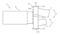
- the first stage compressor body 4 and the second stage compressor body 6 vibrates with a plurality of natural vibration modes.
- the plurality of natural vibration modes there are modes that are particularly burdensome on the screw compressor 2. It is preferable to reduce the vibration in such a burdensome mode in order to improve durability.
- a part of the first rib part 21 and a part of the second rib part 22 are integrated with the side wall 10c of the gear box 10, thereby improving the rigidity of the first rib part 21 and the second rib part 22. Can do. Further, by integrating a part of the upper part of the annular rib 20 with the top plate 10e of the gear box 10, the rigidity of the upper part of the annular rib 20 can be improved and the rigidity with respect to the specific natural vibration mode can be improved. . Therefore, both vibration and torsion in the specific natural vibration mode can be suppressed.
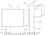
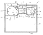
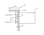
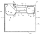
- Second stage compressor body 2 Screw compressor 4 First stage compressor body 6 Second stage compressor body 8 Motor (electric motor) DESCRIPTION OF SYMBOLS 10 Gear box 10a Front wall 10b Rear wall 10c Side wall 10d Bottom plate 10e Top plate 10f First attachment hole 10g Second attachment hole 12 Support member 14a, 14b Anti-vibration rubber 20 Annular rib 20a First rib region 20b Second rib region 20c First 3 rib area 21 1st rib part 22 2nd rib part 23 3rd rib part 23a center upper side rib 23b center lower side rib 24 4th rib part 25 5th rib part 26 6th rib part 27 7th rib part 28 8th Rib part 29 9th rib part 30 10th rib part 31 11th rib part
Landscapes
- Engineering & Computer Science (AREA)
- Mechanical Engineering (AREA)
- General Engineering & Computer Science (AREA)
- Applications Or Details Of Rotary Compressors (AREA)
Abstract
Description
前記第2取付穴の周囲に設けられた部分である第2リブ領域と、前記第1リブ領域と前記第2リブ領域の間の領域である第3リブ領域とを備え、前記第1リブ領域を構成する第1リブ部の間の上下方向の最大間隔が第1間隔であり、前記第2リブ領域を構成する第2リブ部の間の上下方向の最大間隔が第2間隔であり、前記第3リブ領域を構成する第3リブ部の間の上下方向の最大間隔が第3間隔であり、前記第3間隔は、前記第1間隔以下であり、かつ、前記第2間隔以下であり、前記第3リブ部の上側のリブである中央上側リブは、前記第1取付穴の中心と前記第2取付穴の中心とを結んだ仮想中心線よりも上側に配置され、前記第3リブ部の下側のリブである中央下側リブは、前記仮想中心線よりも下側に配置されていることが好ましい。
図1および図2を参照すると、本実施形態に係るスクリュ圧縮機2は、第1段圧縮機本体4と、第2段圧縮機本体6と、モータ(電動機)8と、歯車箱10とを備える。
図7に示す第2実施形態のスクリュ圧縮機2では、第1リブ部21の一部および第2リブ部22の一部が歯車箱10の天板10eおよび側壁10cと一体化されている。本実施形態は、この点を除いて図4の第1実施形態と実質的に同様である。従って、図1から図6に示した構成と同様の部分については説明を省略する。
4 第1段圧縮機本体
6 第2段圧縮機本体
8 モータ(電動機)
10 歯車箱
10a 前壁
10b 後壁
10c 側壁
10d 底板
10e 天板
10f 第1取付穴
10g 第2取付穴
12 支持部材
14a,14b 防振ゴム
20 環状リブ
20a 第1リブ領域
20b 第2リブ領域
20c 第3リブ領域
21 第1リブ部
22 第2リブ部
23 第3リブ部
23a 中央上側リブ
23b 中央下側リブ
24 第4リブ部
25 第5リブ部
26 第6リブ部
27 第7リブ部
28 第8リブ部
29 第9リブ部
30 第10リブ部
31 第11リブ部
Claims (14)
- スクリュロータにより流体を圧縮する第1段圧縮機本体および第2段圧縮機本体と、
前記第1段圧縮機本体および前記第2段圧縮機本体を駆動する電動機と、
前記第1段圧縮機本体および前記第2段圧縮機本体と前記電動機とに接続され、前記電動機の駆動力を前記スクリュロータに伝達し、前記第1段圧縮機本体を取り付ける第1取付穴および前記第2段圧縮機本体を取り付ける第2取付穴を有し、前記第1取付穴および前記第2取付穴の両方を囲む環状リブが設けられている歯車箱と
を備える、スクリュ圧縮機。 - 前記環状リブは、
前記第1取付穴の周囲に設けられた部分である第1リブ領域と、
前記第2取付穴の周囲に設けられた部分である第2リブ領域と、
前記第1リブ領域と前記第2リブ領域との間の領域である第3リブ領域とを備え、
前記第1リブ領域を構成する第1リブ部の間の上下方向の最大間隔が第1間隔であり、
前記第2リブ領域を構成する第2リブ部の間の上下方向の最大間隔が第2間隔であり、
前記第3リブ領域を構成する第3リブ部の間の上下方向の最大間隔が第3間隔であり、
前記第3間隔は、前記第1間隔以下であり、かつ、前記第2間隔以下であり、
前記第3リブ部の上側のリブである中央上側リブは、前記第1取付穴の中心と前記第2取付穴の中心とを結んだ仮想中心線よりも上側に配置され、
前記第3リブ部の下側のリブである中央下側リブは、前記仮想中心線よりも下側に配置されている、請求項1に記載のスクリュ圧縮機。 - 前記中央上側リブと前記中央下側リブの間の前記歯車箱の板厚は、前記歯車箱の他の部分の板厚の平均値よりも厚い、請求項2に記載のスクリュ圧縮機。
- 前記第1リブ部と前記中央上側リブとの接続部と、前記第1リブ部と前記中央下側リブとの接続部とを接続する第4リブ部と、
前記第2リブ部と前記中央上側リブとの接続部と、前記第2リブ部と前記中央下側リブとの接続部とを接続する第5リブ部と
を備える、請求項2または請求項3に記載のスクリュ圧縮機。 - 前記第1取付穴の外周と、前記第1リブ部または前記第4リブ部とを接続する第6リブ部を備える、請求項4に記載のスクリュ圧縮機。
- 前記第2取付穴の外周と、前記第2リブ部または前記第5リブ部とを接続する第7リブ部を備える、請求項4に記載のスクリュ圧縮機。
- 前記中央上側リブと前記中央下側リブとの間に、前記中央上側リブまたは前記中央下側リブに沿って延びる、もしくは前記中央上側リブと前記中央下側リブとが成す角度の範囲内で前記中央下側リブに沿って延びる第8リブ部を備える、請求項2または請求項3に記載のスクリュ圧縮機。
- 前記第1リブ部の一部が前記歯車箱の側壁と一体となっている、請求項2または請求項3に記載のスクリュ圧縮機。
- 前記第1リブ部と前記歯車箱の側壁とを接続する第9リブ部を備える、請求項2または請求項3に記載のスクリュ圧縮機。
- 前記第2リブ部の一部が前記歯車箱の側壁と一体となっている、請求項2または請求項3に記載のスクリュ圧縮機。
- 前記第2リブ部と前記歯車箱の側壁とを接続する第10リブ部を備える、請求項2または請求項3に記載のスクリュ圧縮機。
- 前記第1リブ部の一部、前記第2リブ部の一部、または前記中央上側リブの一部が前記歯車箱の天板と一体となっている、請求項2または請求項3に記載のスクリュ圧縮機。
- 前記第1リブ部、前記第2リブ部、または前記中央上側リブと前記歯車箱の天板とを接続する第11リブ部を備える、請求項2または請求項3に記載のスクリュ圧縮機。
- 前記歯車箱の板厚の平均値よりも前記環状リブの高さが大きい、請求項1から請求項3のいずれか1項に記載のスクリュ圧縮機。
Priority Applications (3)
| Application Number | Priority Date | Filing Date | Title |
|---|---|---|---|
| US16/060,065 US10947976B2 (en) | 2015-12-17 | 2016-11-15 | Screw compressor |
| CN201680070575.8A CN108291546B (zh) | 2015-12-17 | 2016-11-15 | 螺杆式压缩机 |
| KR1020187016243A KR102038937B1 (ko) | 2015-12-17 | 2016-11-15 | 스크루 압축기 |
Applications Claiming Priority (2)
| Application Number | Priority Date | Filing Date | Title |
|---|---|---|---|
| JP2015246281A JP6573543B2 (ja) | 2015-12-17 | 2015-12-17 | スクリュ圧縮機 |
| JP2015-246281 | 2015-12-17 |
Publications (1)
| Publication Number | Publication Date |
|---|---|
| WO2017104334A1 true WO2017104334A1 (ja) | 2017-06-22 |
Family
ID=59056515
Family Applications (1)
| Application Number | Title | Priority Date | Filing Date |
|---|---|---|---|
| PCT/JP2016/083831 Ceased WO2017104334A1 (ja) | 2015-12-17 | 2016-11-15 | スクリュ圧縮機 |
Country Status (6)
| Country | Link |
|---|---|
| US (1) | US10947976B2 (ja) |
| JP (1) | JP6573543B2 (ja) |
| KR (1) | KR102038937B1 (ja) |
| CN (1) | CN108291546B (ja) |
| TW (1) | TWI628360B (ja) |
| WO (1) | WO2017104334A1 (ja) |
Families Citing this family (1)
| Publication number | Priority date | Publication date | Assignee | Title |
|---|---|---|---|---|
| DE102021111297A1 (de) * | 2021-04-30 | 2022-11-03 | CompAir Drucklufttechnik - Zweigniederlassung der Gardner Denver Deutschland GmbH | Antriebssystem für einen mehrstufiger Schraubenverdichter |
Citations (2)
| Publication number | Priority date | Publication date | Assignee | Title |
|---|---|---|---|---|
| JPS5315610A (en) * | 1976-07-28 | 1978-02-13 | Hitachi Ltd | Screw fluid machine |
| JPS5353009A (en) * | 1976-10-25 | 1978-05-15 | Hitachi Ltd | Screw type fluid machine |
Family Cites Families (16)
| Publication number | Priority date | Publication date | Assignee | Title |
|---|---|---|---|---|
| US2669881A (en) * | 1950-09-21 | 1954-02-23 | Richard H Skidmore | Gear reduction unit |
| US3407996A (en) * | 1966-06-22 | 1968-10-29 | Atlas Copco Ab | Screw compressor units |
| US4174196A (en) * | 1976-07-28 | 1979-11-13 | Hitachi, Ltd. | Screw fluid machine |
| SE443625B (sv) * | 1982-06-07 | 1986-03-03 | Atlas Copco Ab | Vexelladshus |
| BE1011158A3 (nl) | 1997-05-20 | 1999-05-04 | Atlas Copco Airpower Nv | Verbindingsstuk dat de behuizing van een aandrijving met de behuizing van een compressorelement verbindt. |
| DE29904411U1 (de) * | 1999-03-10 | 2000-07-20 | GHH-RAND Schraubenkompressoren GmbH & Co. KG, 46145 Oberhausen | Schraubenkompressor |
| GB2376505B (en) * | 2001-06-11 | 2003-12-17 | Compair Uk Ltd | Improvements in screw compressors |
| DE20110360U1 (de) * | 2001-06-22 | 2002-10-31 | GHH-RAND Schraubenkompressoren GmbH, 46145 Oberhausen | Zweistufiger Schraubenkompressor |
| KR100829665B1 (ko) * | 2005-07-06 | 2008-05-16 | 가부시키가이샤 고베 세이코쇼 | 2단형 스크류 압축기 |
| US8342829B2 (en) * | 2005-12-08 | 2013-01-01 | Ghh Rand Schraubenkompressoren Gmbh | Three-stage screw compressor |
| JP5197141B2 (ja) * | 2008-05-12 | 2013-05-15 | 株式会社神戸製鋼所 | 2段スクリュ圧縮機および冷凍装置 |
| JP5313206B2 (ja) * | 2010-06-11 | 2013-10-09 | 株式会社神戸製鋼所 | スクリュ圧縮機 |
| CN201874822U (zh) * | 2010-09-17 | 2011-06-22 | 厄利孔莱博尔德真空技术有限责任公司 | 螺杆式真空泵 |
| JP5777379B2 (ja) * | 2011-04-05 | 2015-09-09 | 株式会社日立産機システム | 空気圧縮機 |
| KR101876220B1 (ko) | 2012-03-20 | 2018-07-10 | 코웨이 주식회사 | 압축기 고정구조체 |
| JP6228868B2 (ja) * | 2014-03-10 | 2017-11-08 | 株式会社神戸製鋼所 | スクリュ圧縮機 |
-
2015
- 2015-12-17 JP JP2015246281A patent/JP6573543B2/ja active Active
-
2016
- 2016-11-15 CN CN201680070575.8A patent/CN108291546B/zh active Active
- 2016-11-15 US US16/060,065 patent/US10947976B2/en active Active
- 2016-11-15 WO PCT/JP2016/083831 patent/WO2017104334A1/ja not_active Ceased
- 2016-11-15 KR KR1020187016243A patent/KR102038937B1/ko active Active
- 2016-12-06 TW TW105140257A patent/TWI628360B/zh active
Patent Citations (2)
| Publication number | Priority date | Publication date | Assignee | Title |
|---|---|---|---|---|
| JPS5315610A (en) * | 1976-07-28 | 1978-02-13 | Hitachi Ltd | Screw fluid machine |
| JPS5353009A (en) * | 1976-10-25 | 1978-05-15 | Hitachi Ltd | Screw type fluid machine |
Also Published As
| Publication number | Publication date |
|---|---|
| TW201734318A (zh) | 2017-10-01 |
| KR20180084863A (ko) | 2018-07-25 |
| CN108291546B (zh) | 2020-04-24 |
| US10947976B2 (en) | 2021-03-16 |
| JP6573543B2 (ja) | 2019-09-11 |
| US20180355867A1 (en) | 2018-12-13 |
| TWI628360B (zh) | 2018-07-01 |
| KR102038937B1 (ko) | 2019-10-31 |
| JP2017110587A (ja) | 2017-06-22 |
| CN108291546A (zh) | 2018-07-17 |
Similar Documents
| Publication | Publication Date | Title |
|---|---|---|
| WO2015068754A1 (ja) | 電動圧縮機の取付構造 | |
| EP2265821B1 (en) | Muffler for compressor | |
| JP6258615B2 (ja) | 電動圧縮機 | |
| CN105179271A (zh) | 离心风机或斜流风机 | |
| JP6094497B2 (ja) | 電動圧縮機、及び電動圧縮機の製造方法 | |
| JP6760148B2 (ja) | 車両用電動圧縮機 | |
| JP6573543B2 (ja) | スクリュ圧縮機 | |
| CN103244658B (zh) | 变速器的壳体结构 | |
| CN104514715B (zh) | 涡旋式流体机械 | |
| KR102049877B1 (ko) | 스크루 압축기 | |
| US20200200171A1 (en) | Screw compressor | |
| CN100483034C (zh) | 高处设置型空调机的顶板结构 | |
| JP6407306B2 (ja) | 車両用のポンプ装置および車両用のブラケット | |
| JP6506030B2 (ja) | 電動圧縮機の取付構造 | |
| JP6339434B2 (ja) | 圧縮機 | |
| JP2012241841A (ja) | 駆動装置 | |
| CN219181309U (zh) | 电驱壳体、电驱系统以及电动设备 | |
| CN104785797B (zh) | 主轴箱及主轴箱传动系统 | |
| CN205401662U (zh) | 用于电动汽车的减速器后壳体 | |
| CN109098969B (zh) | 一种压缩机 | |
| CN107115063A (zh) | 尘杯及吸尘器 | |
| WO2011052146A1 (ja) | 密閉型圧縮機 | |
| JP2016008509A (ja) | スクリュ圧縮機 | |
| JP2016205183A (ja) | 送風装置 | |
| JP2007016749A (ja) | コンプレッサ用アキュムレータ |
Legal Events
| Date | Code | Title | Description |
|---|---|---|---|
| 121 | Ep: the epo has been informed by wipo that ep was designated in this application |
Ref document number: 16875318 Country of ref document: EP Kind code of ref document: A1 |
|
| ENP | Entry into the national phase |
Ref document number: 20187016243 Country of ref document: KR Kind code of ref document: A |
|
| WWE | Wipo information: entry into national phase |
Ref document number: 1020187016243 Country of ref document: KR |
|
| NENP | Non-entry into the national phase |
Ref country code: DE |
|
| 122 | Ep: pct application non-entry in european phase |
Ref document number: 16875318 Country of ref document: EP Kind code of ref document: A1 |