WO2017104303A1 - 質量分析装置 - Google Patents
質量分析装置 Download PDFInfo
- Publication number
- WO2017104303A1 WO2017104303A1 PCT/JP2016/083150 JP2016083150W WO2017104303A1 WO 2017104303 A1 WO2017104303 A1 WO 2017104303A1 JP 2016083150 W JP2016083150 W JP 2016083150W WO 2017104303 A1 WO2017104303 A1 WO 2017104303A1
- Authority
- WO
- WIPO (PCT)
- Prior art keywords
- rod
- mass spectrometer
- electrodes
- shaped electrodes
- distance
- Prior art date
- Legal status (The legal status is an assumption and is not a legal conclusion. Google has not performed a legal analysis and makes no representation as to the accuracy of the status listed.)
- Ceased
Links
Images



Classifications
-
- H—ELECTRICITY
- H01—ELECTRIC ELEMENTS
- H01J—ELECTRIC DISCHARGE TUBES OR DISCHARGE LAMPS
- H01J49/00—Particle spectrometers or separator tubes
- H01J49/02—Details
- H01J49/06—Electron- or ion-optical arrangements
- H01J49/062—Ion guides
- H01J49/063—Multipole ion guides, e.g. quadrupoles, hexapoles
-
- H—ELECTRICITY
- H01—ELECTRIC ELEMENTS
- H01J—ELECTRIC DISCHARGE TUBES OR DISCHARGE LAMPS
- H01J49/00—Particle spectrometers or separator tubes
- H01J49/004—Combinations of spectrometers, tandem spectrometers, e.g. MS/MS, MSn
- H01J49/0045—Combinations of spectrometers, tandem spectrometers, e.g. MS/MS, MSn characterised by the fragmentation or other specific reaction
- H01J49/005—Combinations of spectrometers, tandem spectrometers, e.g. MS/MS, MSn characterised by the fragmentation or other specific reaction by collision with gas, e.g. by introducing gas or by accelerating ions with an electric field
-
- H—ELECTRICITY
- H01—ELECTRIC ELEMENTS
- H01J—ELECTRIC DISCHARGE TUBES OR DISCHARGE LAMPS
- H01J49/00—Particle spectrometers or separator tubes
- H01J49/26—Mass spectrometers or separator tubes
- H01J49/34—Dynamic spectrometers
- H01J49/42—Stability-of-path spectrometers, e.g. monopole, quadrupole, multipole, farvitrons
-
- H—ELECTRICITY
- H01—ELECTRIC ELEMENTS
- H01J—ELECTRIC DISCHARGE TUBES OR DISCHARGE LAMPS
- H01J49/00—Particle spectrometers or separator tubes
- H01J49/26—Mass spectrometers or separator tubes
- H01J49/34—Dynamic spectrometers
- H01J49/42—Stability-of-path spectrometers, e.g. monopole, quadrupole, multipole, farvitrons
- H01J49/4205—Device types
- H01J49/421—Mass filters, i.e. deviating unwanted ions without trapping
- H01J49/4215—Quadrupole mass filters
Definitions
- the present invention relates to a mass spectrometry system using a quadrupole mass spectrometer, and more particularly to mass spectrometry that requires high sensitivity and high resolution, such as in the case of analysis of an in vivo sample.
- one of the multiple quadrupole electrode systems is filled with a buffer gas and acts as a collision chamber for colliding the target ions with the buffer gas (Collision Induced Dissociation).
- ions passing through the quadrupole electrode system in the collision chamber are slowed by the collision with the buffer gas, so that the passage through the collision chamber is delayed and the mass spectrum as a result of mass spectrometry is adversely affected, such as crosstalk. Is likely to affect. For this reason, means for generating a potential gradient of a DC component toward the traveling direction of ions is employed for the purpose of accelerating decelerated ions.
- Patent Document 1 as a means for accelerating ions in a collision chamber, as shown in FIG. 5, four electrodes (4-2-a, 4 -2-b, 4-2-c, 4-2-d) are arranged, and RF voltage -Vcos ⁇ t and minute DC voltage ⁇ Uy are applied to the opposing electrodes (4-2-a, 4-2-c). Superimposition is applied, and RF voltage + Vcos ⁇ t and minute DC voltage ⁇ Ux are superimposed and applied to the other opposing electrode (4-2-b, 4-2-d). As a result, a potential gradient of the DC component is generated along the central axis of the electrode system.
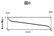
- FIG. 6 shows the numerical analysis result of the potential potential of the DC soot component generated on the central axis at this time. It can be seen that the potential potential of the DC component is inclined along the ion traveling direction (z direction). As a result, ions passing through the interior are accelerated.
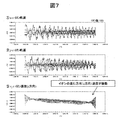
- FIG. 7 shows the result of analyzing the trajectory and velocity of 100 ions passing through the interior. If you look at the analysis results of the velocity in the z direction, you can see that the velocity is oscillating significantly.
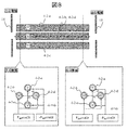
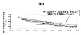
- FIG. 8 in the case of a normal electrode system in which four electrodes having the same electrode diameter are arranged in parallel, the velocity in the z direction is decelerated by collision with a buffer gas as shown in FIG. As shown in FIG. 7, there is no vibration.
- FIG. 8 shows the case of a normal electrode system in which four electrodes having the same electrode diameter are arranged in parallel.
- FIG. 10 shows the result of plotting the z-direction velocity v z at the electrode system outlet for each ion in the case of the system shown in FIG. 5 and the system shown in FIG.
- the dispersion width of v z in the case of the system shown in FIG. 5 is about 5 times wider than that in the system shown in FIG. Since this is closely related to the difference in ion transit time, that is, the width of the mass spectrum, it is likely to lead to a reduction in resolution.
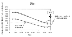
- Fig. 11 shows the potential analysis result of the RF component on the central axis. Since the potential potential of the RF component changes according to the z coordinate, that is, an RF electric field is also generated in the z direction, ions are vibrated in the z direction, and the velocity of the ions is also oscillated and dispersed at the exit. .
- a first mass spectrometer includes 2n rod-shaped electrodes, a DC voltage U and a high-frequency voltage V RF cos ⁇ t applied to the rod-shaped electrodes, and a gap between the rod-shaped electrodes.
- a mass spectrometer including a control unit that generates a multipole electric field of a high-frequency quadrupole or more, wherein a distance between at least one pair of opposing rod-shaped electrodes among the rod-shaped electrodes is such that an entrance portion into which ions enter Different at the exit where ions exit, The distance between the at least one pair of opposing rod-shaped electrodes gradually decreases from the inlet portion toward the outlet portion.
- the second mass spectrometer of the present invention includes 2n rod-shaped electrodes, A mass spectrometer comprising a controller that applies a DC voltage U and a high-frequency voltage V RF cos ⁇ t to the rod-shaped electrode, and generates a multipole electric field of a high-frequency quadrupole or more between the rod-shaped electrodes, The distance between at least one pair of opposing rod-shaped electrodes among the rod-shaped electrodes is different between an entrance portion where ions are incident and an exit portion where ions are emitted, The distance between the at least one pair of opposing rod-shaped electrodes gradually increases from the inlet portion toward the outlet portion.
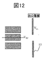
- FIG. 2 is a schematic diagram of a quadrupole electrode system and a subsequent outlet electrode. It is a figure showing the result of having analyzed the potential potential on the central axis in the vicinity of the quadrupole system outlet in the opposite phase.
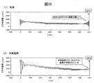
- FIG. 15 is a diagram showing the results of analyzing the z-direction ion velocity in the case of the system shown in FIG. 5 (conventional) and in the system shown in FIG. 14 (second example). It is the schematic of the structure of a quadrupole electrode system and the voltage application method by 3rd Example of this invention. It is the schematic of the structure of a quadrupole electrode system and the voltage application method by 3rd Example of this invention. It is the schematic of the structure of a quadrupole electrode system and the voltage application method by 3rd Example of this invention. It is the schematic of the structure of a quadrupole electrode system and the voltage application method by 3rd Example of this invention.
- a potential distribution is generated that suppresses the oscillation of ions in the z direction near the exit.
- the following two means are considered necessary.
- the RF electric field generation in the z direction is suppressed by making the potential potential of the RF component substantially constant (the change is small or does not change) near the exit.
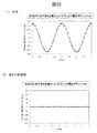
- FIG. 20 (1) shows the result of analyzing the time change of the potential potential on the central axis at the outlet at this time. In this case, it can be seen that it vibrates at the same frequency as the RF voltage frequency with an amplitude of about 173V.
- the outlet electrode is usually only a DC component voltage, and no RF voltage is applied. Therefore, an RF electric field equivalent to the RF electric field generated on the central axis is formed between the multipole electrode system and the outlet electrode. Will be generated.
- the potential potential of the RF component is substantially constant with respect to the z coordinate, and further, near the exit
- the generation of the RF electric field in the direction of the ions is suppressed (the ion oscillation in the z direction is suppressed).
- the mass spectrometer is capable of high-sensitivity and high-resolution analysis that can achieve both reduction in velocity dispersion width.
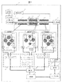
- FIG. 1 is a view showing a tandem quadrupole mass spectrometer composed of three stages of QMS, which is a feature of the first embodiment
- FIG. 2 is an overall configuration diagram of the mass spectrometer system of this embodiment.
- an analysis flow is shown for the mass spectrometry system 11.
- Samples subject to mass spectrometry are samples that are separated and fractionated in time in a pretreatment system 1 such as gas chromatography (GC) or liquid chromatography (LC), and are ionized one after another in the ionization unit 2.
- a pretreatment system 1 such as gas chromatography (GC) or liquid chromatography (LC)
- the ions pass through the ion transport unit 3 and enter the mass analysis unit 4 to be separated by mass.
- m is the ion mass
- Z is the charge valence of the ion.
- the voltage to the mass analysis unit 4 is applied from the voltage source 9 while being controlled by the control unit 8.
- the ions finally separated and passed are detected by the ion detector 5 and organized and processed by the data processor 6, and the mass analysis data as the analysis result is displayed on the display unit 7.
- Control unit for the whole of this series of mass analysis process ionization of sample, transport and incidence of sample ion beam to mass analysis unit 4, mass separation process, ion detection, data processing, command processing of user input unit 10) Controlled by 8.
- the mass separation unit 4 is composed of four stages of quadrupole mass spectrometers (QMS) composed of four rod-like electrodes, which are substantially coaxially arranged in three stages.
- QMS quadrupole mass spectrometers
- the four rod-shaped electrodes are cylindrical as shown in the x, y sectional view of the rod-shaped electrode. It may be an electrode, or may be a rod-like electrode having a bipolar surface shape as indicated by a dotted line.
- the ionized sample ions are introduced along the central axis (z direction) between the rod-shaped electrodes, and pass through the high-frequency electric field of equation (8).
- the stability of ion trajectories in the x and y directions at this time is determined by the following dimensionless parameters a i and q i derived from the equation of motion of ions between the rod-shaped electrodes (Mathieu equation).
- the dimensionless parameters a i and q i are stability parameters in the i-th stage QMS.
- r in (10) 0 half the distance between opposing rod electrodes, e is elementary charge, m / Z is the mass-to-charge ratio of ions, U is the DC voltage applied to the rod electrodes , V and ⁇ are the amplitude and angular vibration frequency of the high frequency voltage.
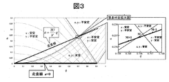
- each ion species corresponds to a different (a i , q i ) point on the aq plane of FIG. 3 according to its mass-to-charge ratio m / Z.
- all the different (a i , q i ) points of each ion species exist on the straight line of the following expression (11).
- FIG. 3 shows the quantitative range (stable transmission region) of a i and q i giving a stable solution for ion trajectories in both the x and y directions.
- the stable transmission region of FIG. It is necessary to adjust the U / V ratio so as to intersect with the vicinity of the apex of (FIG. 3). While stably transmitting ions pass between the rod-like electrodes in the z direction while vibrating, the destabilized ions radiate the vibrations and exit in the x and y directions.
- the numerical analysis result of the potential potential of the DC component generated on the central axis at this time is shown in FIG. It can be seen that the potential potential of the DC component is inclined along the ion traveling direction (z direction). As a result, ions passing through the interior are accelerated. Like the potential potential of the DC component, the potential potential of the RF component also slopes (Fig. 11).
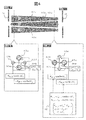
- the center near the exit of the second-stage QMS electrode system in order to generate a potential distribution that suppresses the oscillation of ions in the z direction near the exit of the second-stage QMS electrode system, the center near the exit of the second-stage QMS electrode system. Adjust the voltage so that the RF component of the potential potential on the axis is zero.
- both ends, or at least the outlet side are z It is characterized by being parallel to the direction (distances dx and dy between the opposing electrodes are constant with respect to the z coordinate). That is, by this, the potential potential of the RF component is made substantially constant with respect to the z coordinate near the exit (change is small or does not change), thereby suppressing the generation of the RF electric field in the z direction.
- the parallel distance can be, for example, a distance of 1/100 or more and less than 2/3 of the entire length of the rod-shaped electrode from the outlet portion.
- FIG. 11 shows the potential potential of the RF component.
- the RF component potential is constant with respect to z near the exit.
- the potential potential of the RF component at the outlet is shown in FIG. Is zero.
- the result of analyzing the actual velocity distribution at K is shown in FIG. Compared to the white plot, it can be confirmed that the dispersion width of the z-direction velocity is reduced to about 1/5.
- FIGS. 15 (1) and 15 (2) show the results of analyzing the z-direction ion velocity inside Q2 in the conventional electrode system of FIG. 5 and the electrode system of this example. According to Fig. 15 (1), the z-direction velocity of ions toward the Q2 exit vibrates violently, while in Fig. 15 (2), it can be seen that the ion z-direction velocity toward the exit is suppressed. .
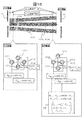
- the distance between the opposing electrodes in the rod-shaped electrode 4-2-2a, 4-2-b, 4-2-c, 4-2-d of Q2 is z
- an electrode system in which the cylindrical electrodes themselves are arranged obliquely without largely changing the diameter of the cylindrical electrodes may be used.
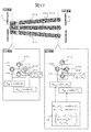
- a system may be adopted in which the distance between the electrodes is gradually changed stepwise while gradually shifting the distance. Also, as shown in FIG.
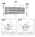
- the interelectrode distance dx is constant for the X counter electrode in FIG. 18, and the interelectrode distance dy varies according to the z coordinate for the Y counter electrode.
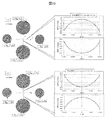
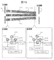
- the electrode system is an electrode system in which the inter-electrode distances dx and dy are dx ⁇ dy, as shown in FIG.
- 1 is a pretreatment system
- 2 is an ionization section
- 3 is an ion transport section
- 4 is a mass spectrometry section
- 4-1-a, 4-1-b, 4-1-c, and 4-1-d are the first stage.
- Four rod-shaped electrodes in the quadrupole electrode system of the eye, 4-2-2a, 4-2-b, 4-2-c and 4-2-d are 4 in the quadrupole electrode system of the second stage.
- 4-3-a, 4-3-b, 4-3-c, 4-3-d are the four rod electrodes in the third-stage quadrupole electrode system
- the mass spectrometer 5 is an ion detection unit
- 6 is a data processing unit
- 7 is a display unit
- 8 is a control unit
- 9 is a voltage source
- 10 is a user input unit
- 11 is an entire tandem mass spectrometry system
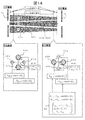
- 12 is a content of applied voltage control
- 13 is a collision chamber
- 14 is an inlet electrode of the second-stage quadrupole electrode system
- 15 is an outlet electrode of the second-stage quadrupole electrode system.
Landscapes
- Chemical & Material Sciences (AREA)
- Analytical Chemistry (AREA)
- Chemical Kinetics & Catalysis (AREA)
- Electron Tubes For Measurement (AREA)
- Other Investigation Or Analysis Of Materials By Electrical Means (AREA)
Abstract
Description
前記少なくとも1組の対向する棒状電極間の距離が、入口部から出口部に向けて徐々に減少することを特徴としている。
前記棒状電極に直流電圧Uと高周波電圧VRFcosΩtとを印加して、前記棒状電極間に高周波の四重極以上の多重極電界を生成させる制御部とを備えた質量分析装置であって、
棒状電極のうち少なくとも一組の対向する棒状電極間の距離が、イオンが入射する入口部とイオンが出射する出口部において異なり、
前記少なくとも1組の対向する棒状電極間の距離が、入口部から出口部に向けて徐々に増加することを特徴としている。
まず、第一の実施例について、図1~4,6,11を用いて説明する。図1は第一実施例の特徴である、3段のQMSから成るタンデム型四重極質量分析装置を示す図であり、図2は、本実施例の質量分析システムの全体構成図である。まず、質量分析システム11に対して、分析フローを示す。質量分析対象の試料は、ガスクロマトグラフィー(GC)又は液体クロマトグラフィー(LC)などの前処理系1にて、時間的に分離・分画され、次々とイオン化部2にて、イオン化された試料イオンは、イオン輸送部3を通って、質量分析部4に入射され、質量分離される。ここで、mはイオン質量、Zはイオンの帯電価数である。質量分析部4への電圧は、制御部8から制御されながら、電圧源9から印加される。最終的に分離され通過してきたイオンは、イオン検出部5で検出され、データ処理部6でデータ整理・処理され、その分析結果である質量分析データは表示部7にて表示される。この一連の質量分析過程(試料のイオン化、試料イオンビームの質量分析部4への輸送及び入射、質量分離過程、及び、イオン検出、データ処理、ユーザ入力部10の指令処理)の全体を制御部8で制御している。

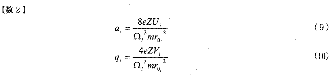
また、 (9)、(10)式中のr0は対向するロッド電極間の距離の半値、eは素電荷、m/Zはイオンの質量対電荷比、Uはロッド電極に印加する直流電圧、V、Ωは高周波電圧の振幅及び角振動周波数である。r0、U、V、Ωの値が決まると、各イオン種はその質量対電荷比m/Zに応じて、図3のa-q平面上の異なる(ai,qi)点に対応する。このとき、(9)、(10)の式から、各イオン種の異なる(ai,qi)点は、次の(11)式の直線上に全て存在することになる。


Claims (14)
- 2n本の棒状電極と、
前記棒状電極に直流電圧Uと高周波電圧VRFcosΩtとを印加して、前記棒状電極間に高周波の四重極以上の多重極電界を生成させる制御部とを備えた質量分析装置であって、
棒状電極のうち少なくとも一組の対向する棒状電極間の距離が、イオンが入射する入口部とイオンが出射する出口部において異なり、
前記少なくとも1組の対向する棒状電極間の距離が、入口部から出口部に向けて徐々に減少することを特徴とする質量分析装置。 - 2n本の棒状電極と、
前記棒状電極に直流電圧Uと高周波電圧VRFcosΩtとを印加して、前記棒状電極間に高周波の四重極以上の多重極電界を生成させる制御部とを備えた質量分析装置であって、
棒状電極のうち少なくとも一組の対向する棒状電極間の距離が、イオンが入射する入口部とイオンが出射する出口部において異なり、
前記少なくとも1組の対向する棒状電極間の距離が、入口部から出口部に向けて徐々に増加することを特徴とする質量分析装置。 - 請求項2に記載の質量分析装置であって、
前記棒状電極のうち、少なくとも1組の対向する棒状電極間の距離が、入口部から出口部に向けて徐々に減少し、別の1組の対向する棒状電極間の距離が、入口部から出口部に向けて徐々に増加し、
それぞれの組の電極が互いに90度回転した位置に配置されていることを特徴とする質量分析装置。 - 請求項1または2に記載の質量分析装置であって、
棒状電極は、互いに対向する棒状電極を複数組備えて成り、
前記制御部は、電極組間で高周波電圧VRFcosΩtの振幅値VRFが異なるように、各電極組に対して高周波電圧VRFcosΩtを印加することを特徴とする質量分析装置。 - 請求項1または2に記載の質量分析装置であって、
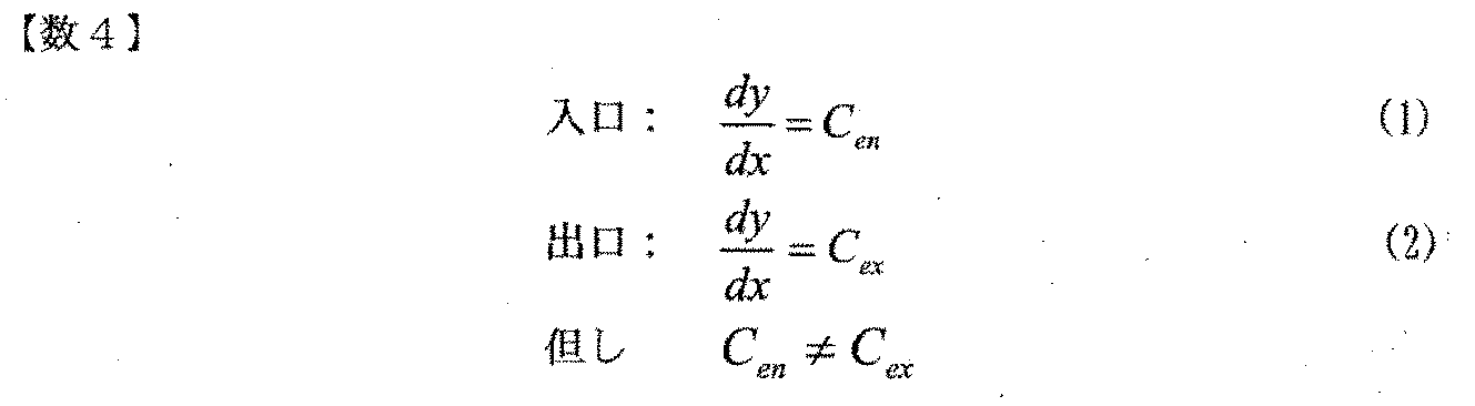
出口部付近における、互いに対向する2組の電極間の距離を各々、dx、dyとするとき、
前記制御部は、dx、dyの値に応じて、2組の電極間のそれぞれの高周波電圧VRFcosΩtの振幅値VRFx、VRFyが互いに異なるように制御することを特徴とする質量分析装置。 - 請求項5に記載の質量分析装置であって、
dy/dx=Cとするとき、
前記制御部は、VRFy/VRFx∝C2 となるように振幅値VRFx、VRFyを制御することを特徴とする質量分析装置。 - 請求項5に記載の質量分析装置であって、
dy/dx=Cとするとき、
前記制御部は、VRFy/VRFx= C2 となるように振幅値VRFx、VRFyを制御することを特徴とする質量分析装置。 - 請求項1または2に記載の質量分析装置において、
前記棒状電極は、入口部から出口部に向けて傾斜して配置されていることを特徴とする質量分析装置。 - 請求項1または2に記載の質量分析装置であって、
出口部から棒状電極の全体長さの1/100以上2/3未満の距離では、対向する電極が互いに平行に設置されることを特徴とする質量分析装置。 - 請求項1または2に記載の質量分析装置であって、
前記棒状電極は、入口部から出口部に向けて階段状に徐々に距離が変化することを特徴とする質量分析装置。 - 請求項1または2に記載の質量分析装置であって、
出口部付近では、対向する複数の電極組の電極間距離が略同一であることを特徴とする質量分析装置。 - 請求項1または2に記載の質量分析装置であって、
棒状電極のうち少なくとも1組の対向する棒状電極は電極間の距離が同一、かつ、平行に配置されていることを特徴とする質量分析装置。 - 請求項1または2に記載の質量分析装置であって、
前記棒状電極が複数セット、タンデム状に連ねられて成り、
複数セットのうち、ガス衝突によりイオンを解離するための棒状電極において、棒状電極のうち少なくとも一組の対向する棒状電極間の距離が、イオンが入射する入口部とイオンが出射する出口部において異なることを特徴とする質量分析装置。 - 請求項1または2に記載の質量分析装置であって、
出口部付近及び入口部付近の少なくともいずれかにおいて対向する電極が互いに平行に設置されることを特徴とする質量分析装置。
Priority Applications (4)
| Application Number | Priority Date | Filing Date | Title |
|---|---|---|---|
| US16/060,132 US10607825B2 (en) | 2015-12-17 | 2016-11-09 | Mass spectrometer |
| GB1809190.0A GB2559527B (en) | 2015-12-17 | 2016-11-09 | Mass spectrometer |
| DE112016005070.4T DE112016005070B4 (de) | 2015-12-17 | 2016-11-09 | Massenspektrometer |
| CN201680072855.2A CN108369890B (zh) | 2015-12-17 | 2016-11-09 | 质量分析装置 |
Applications Claiming Priority (2)
| Application Number | Priority Date | Filing Date | Title |
|---|---|---|---|
| JP2015245783A JP6659345B2 (ja) | 2015-12-17 | 2015-12-17 | 質量分析装置 |
| JP2015-245783 | 2015-12-17 |
Publications (1)
| Publication Number | Publication Date |
|---|---|
| WO2017104303A1 true WO2017104303A1 (ja) | 2017-06-22 |
Family
ID=59056544
Family Applications (1)
| Application Number | Title | Priority Date | Filing Date |
|---|---|---|---|
| PCT/JP2016/083150 Ceased WO2017104303A1 (ja) | 2015-12-17 | 2016-11-09 | 質量分析装置 |
Country Status (6)
| Country | Link |
|---|---|
| US (1) | US10607825B2 (ja) |
| JP (1) | JP6659345B2 (ja) |
| CN (1) | CN108369890B (ja) |
| DE (1) | DE112016005070B4 (ja) |
| GB (1) | GB2559527B (ja) |
| WO (1) | WO2017104303A1 (ja) |
Families Citing this family (5)
| Publication number | Priority date | Publication date | Assignee | Title |
|---|---|---|---|---|
| CN109238962B (zh) * | 2018-08-28 | 2023-09-29 | 广东中科谛听科技有限公司 | 快速设定光谱分析间隙的记忆机构 |
| WO2020241454A1 (ja) * | 2019-05-31 | 2020-12-03 | 株式会社新日本科学 | クロマトグラフ質量分析装置を用いた質量分析方法 |
| US10985002B2 (en) * | 2019-06-11 | 2021-04-20 | Perkinelmer Health Sciences, Inc. | Ionization sources and methods and systems using them |
| CN110648896B (zh) * | 2019-08-16 | 2022-02-08 | 上海裕达实业有限公司 | 适用于高扫速模式的线性离子阱及分析方法 |
| CN120854253A (zh) * | 2024-04-25 | 2025-10-28 | 株式会社岛津制作所 | 离子导引装置以及质谱仪 |
Citations (4)
| Publication number | Priority date | Publication date | Assignee | Title |
|---|---|---|---|---|
| JPH11510946A (ja) * | 1995-08-11 | 1999-09-21 | エムディーエス ヘルス グループ リミテッド | 軸電界を有する分光計 |
| JP2008500684A (ja) * | 2004-05-24 | 2008-01-10 | エムディーエス インコーポレイテッド ドゥーイング ビジネス アズ エムディーエス サイエックス | トラップイオン用の装置および方法 |
| WO2010023706A1 (ja) * | 2008-08-25 | 2010-03-04 | 株式会社島津製作所 | 四重極型質量分析装置及び四重極型質量分析装置の調整方法 |
| JP2015507820A (ja) * | 2011-12-21 | 2015-03-12 | サーモ フィッシャー サイエンティフィック (ブレーメン) ゲーエムベーハー | 衝突セル多重極 |
Family Cites Families (2)
| Publication number | Priority date | Publication date | Assignee | Title |
|---|---|---|---|---|
| US20110049360A1 (en) | 2009-09-03 | 2011-03-03 | Schoen Alan E | Collision/Reaction Cell for a Mass Spectrometer |
| DE102010022184B4 (de) | 2010-05-21 | 2013-04-04 | Bruker Daltonik Gmbh | Mischfrequenz-Stabsystem als Ionenreaktor |
-
2015
- 2015-12-17 JP JP2015245783A patent/JP6659345B2/ja active Active
-
2016
- 2016-11-09 DE DE112016005070.4T patent/DE112016005070B4/de active Active
- 2016-11-09 GB GB1809190.0A patent/GB2559527B/en active Active
- 2016-11-09 CN CN201680072855.2A patent/CN108369890B/zh active Active
- 2016-11-09 WO PCT/JP2016/083150 patent/WO2017104303A1/ja not_active Ceased
- 2016-11-09 US US16/060,132 patent/US10607825B2/en active Active
Patent Citations (4)
| Publication number | Priority date | Publication date | Assignee | Title |
|---|---|---|---|---|
| JPH11510946A (ja) * | 1995-08-11 | 1999-09-21 | エムディーエス ヘルス グループ リミテッド | 軸電界を有する分光計 |
| JP2008500684A (ja) * | 2004-05-24 | 2008-01-10 | エムディーエス インコーポレイテッド ドゥーイング ビジネス アズ エムディーエス サイエックス | トラップイオン用の装置および方法 |
| WO2010023706A1 (ja) * | 2008-08-25 | 2010-03-04 | 株式会社島津製作所 | 四重極型質量分析装置及び四重極型質量分析装置の調整方法 |
| JP2015507820A (ja) * | 2011-12-21 | 2015-03-12 | サーモ フィッシャー サイエンティフィック (ブレーメン) ゲーエムベーハー | 衝突セル多重極 |
Also Published As
| Publication number | Publication date |
|---|---|
| GB2559527A (en) | 2018-08-08 |
| CN108369890B (zh) | 2019-12-06 |
| DE112016005070T5 (de) | 2018-07-19 |
| JP6659345B2 (ja) | 2020-03-04 |
| US20190006164A1 (en) | 2019-01-03 |
| DE112016005070B4 (de) | 2022-02-03 |
| GB2559527B (en) | 2021-10-27 |
| JP2017111988A (ja) | 2017-06-22 |
| GB201809190D0 (en) | 2018-07-25 |
| US10607825B2 (en) | 2020-03-31 |
| CN108369890A (zh) | 2018-08-03 |
Similar Documents
| Publication | Publication Date | Title |
|---|---|---|
| JP6659345B2 (ja) | 質量分析装置 | |
| CN102067273A (zh) | 质量分析装置 | |
| US20210134583A1 (en) | Ion guide device with dc field and associated methods | |
| US8258470B2 (en) | Radio frequency lens for introducing ions into a quadrupole mass analyzer | |
| WO2014141756A1 (ja) | 質量分析システム、及び方法 | |
| US11276544B2 (en) | Dynamic electron impact ion source | |
| JP6277272B2 (ja) | 質量分析装置 | |
| JP6593451B2 (ja) | 四重極マスフィルタ及び四重極型質量分析装置 | |
| CN108352293B (zh) | 四极杆滤质器以及四极杆质谱分析装置 | |
| JP4844557B2 (ja) | 質量分析装置 | |
| WO2016174990A1 (ja) | 質量分析装置 | |
| JP3730527B2 (ja) | 質量分析装置 | |
| JP6711407B2 (ja) | イオンガイド及び質量分析装置 | |
| JP6315732B2 (ja) | 質量分析装置 | |
| Batey et al. | Mass spectrometers | |
| JP6735620B2 (ja) | 質量分析装置 |
Legal Events
| Date | Code | Title | Description |
|---|---|---|---|
| 121 | Ep: the epo has been informed by wipo that ep was designated in this application |
Ref document number: 16875287 Country of ref document: EP Kind code of ref document: A1 |
|
| WWE | Wipo information: entry into national phase |
Ref document number: 112016005070 Country of ref document: DE |
|
| ENP | Entry into the national phase |
Ref document number: 201809190 Country of ref document: GB Kind code of ref document: A Free format text: PCT FILING DATE = 20161109 |
|
| WWE | Wipo information: entry into national phase |
Ref document number: 1809190.0 Country of ref document: GB |
|
| 122 | Ep: pct application non-entry in european phase |
Ref document number: 16875287 Country of ref document: EP Kind code of ref document: A1 |