WO2017104254A1 - 車両用空調装置 - Google Patents
車両用空調装置 Download PDFInfo
- Publication number
- WO2017104254A1 WO2017104254A1 PCT/JP2016/081100 JP2016081100W WO2017104254A1 WO 2017104254 A1 WO2017104254 A1 WO 2017104254A1 JP 2016081100 W JP2016081100 W JP 2016081100W WO 2017104254 A1 WO2017104254 A1 WO 2017104254A1
- Authority
- WO
- WIPO (PCT)
- Prior art keywords
- refrigerant
- heat exchanger
- outlet
- inlet
- valve
- Prior art date
- Legal status (The legal status is an assumption and is not a legal conclusion. Google has not performed a legal analysis and makes no representation as to the accuracy of the status listed.)
- Ceased
Links
Images






Classifications
-
- B—PERFORMING OPERATIONS; TRANSPORTING
- B60—VEHICLES IN GENERAL
- B60H—ARRANGEMENTS OF HEATING, COOLING, VENTILATING OR OTHER AIR-TREATING DEVICES SPECIALLY ADAPTED FOR PASSENGER OR GOODS SPACES OF VEHICLES
- B60H1/00—Heating, cooling or ventilating devices
-
- B—PERFORMING OPERATIONS; TRANSPORTING
- B60—VEHICLES IN GENERAL
- B60H—ARRANGEMENTS OF HEATING, COOLING, VENTILATING OR OTHER AIR-TREATING DEVICES SPECIALLY ADAPTED FOR PASSENGER OR GOODS SPACES OF VEHICLES
- B60H1/00—Heating, cooling or ventilating devices
- B60H1/22—Heating, cooling or ventilating devices the heat source being other than the propulsion plant
-
- B—PERFORMING OPERATIONS; TRANSPORTING
- B60—VEHICLES IN GENERAL
- B60H—ARRANGEMENTS OF HEATING, COOLING, VENTILATING OR OTHER AIR-TREATING DEVICES SPECIALLY ADAPTED FOR PASSENGER OR GOODS SPACES OF VEHICLES
- B60H1/00—Heating, cooling or ventilating devices
- B60H1/32—Cooling devices
Definitions
- the present disclosure relates to a vehicle air conditioner for heating a vehicle interior.
- Patent Document 1 discloses a vehicle air conditioner using a heat pump system in which an indoor heat exchanger and a water refrigerant heat exchanger are provided in a hot water circuit through which engine coolant flows.
- the water-refrigerant heat exchanger heats engine coolant with high-temperature and high-pressure refrigerant discharged from the compressor.
- the indoor heat exchanger heats the air in the vehicle interior with engine coolant heated by a high-temperature and high-pressure refrigerant.
- the temperature of engine cooling water can be raised rapidly using a high-temperature / high-pressure refrigerant.
- the air temperature in the passenger compartment can be raised rapidly.
- a heat pump system in which an indoor heat exchanger and a water refrigerant heat exchanger are provided in a hot water circuit is referred to as a water heating type heat pump system.
- a heat pump system including an indoor heat exchanger that directly heats air with a refrigerant discharged from a compressor can be considered.
- a heat pump system is referred to as an air heating type heat pump system.
- heat is exchanged between the refrigerant and the air, and heat energy remains in the refrigerant, but the residual heat energy is less than that in the water heating type heat pump system.
- Efficiency refers to the energy given to the compressor to drive the compressor as energy Ea, and the heat energy output from the indoor heat exchanger to the air in the passenger compartment as heat energy En, the heat energy relative to the energy Ea.
- the ratio of En is En / Ea.
- an air heating type heat pump system used for air conditioning of a passenger compartment such as a bus
- a refrigeration cycle in which a refrigerant flow is switched by a four-way valve or the like and an indoor heat exchanger is shared between cooling and heating.
- an indoor heat exchanger it is common to arrange an indoor heat exchanger on the ceiling side in the passenger compartment.
- an object of the present disclosure is to provide a vehicle air conditioner that achieves both efficiency and feeling.
- a vehicle air conditioner includes a first air outlet disposed on a ceiling side in a vehicle interior and a second air outlet disposed on a floor side in the vehicle interior.
- Applies to Vehicle air conditioners A first blower for blowing an air flow; A second blower for blowing an air flow; A first indoor heat exchanger that configures a heat pump cycle that circulates the refrigerant together with a compressor that sucks and compresses and discharges the refrigerant, and heats the air flow blown from the first blower by the refrigerant discharged from the compressor
- a heat exchanger for heating that constitutes the heat pump cycle and heats the heat medium with a refrigerant
- a second indoor heat exchanger that heats the air flow blown from the second blower by the heated heat medium
- a switching control unit A switching control unit.
- the first air outlet blows out the air flow heated by the first indoor heat exchanger into the vehicle interior
- the second air outlet blows out the air flow heated by the second indoor heat exchanger into the vehicle interior. Is heated.
- the switching control unit heats the air flow only by the first indoor heat exchanger out of the first indoor heat exchanger and the second indoor heat exchanger and blows it out from the first outlet.
- Switch between 1 heating mode and 2nd heating mode which heats an air flow only with a 2nd indoor heat exchanger out of a 1st indoor heat exchanger and a 2nd indoor heat exchanger, and blows off from a 2nd outlet .
- the air flow is heated only by the first indoor heat exchanger out of the first indoor heat exchanger and the second indoor heat exchanger and blown out from the first outlet, so that the feeling is felt.
- Efficiency can be prioritized.
- the air flow is heated only by the second indoor heat exchanger out of the first indoor heat exchanger and the second indoor heat exchanger and blown out from the second outlet, so that the feeling is higher than the efficiency.
- the heat medium is a fluid used to move heat.
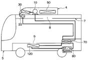
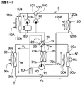
- FIG. 1st Embodiment It is a block diagram which shows the structure of the vehicle air conditioner in 1st Embodiment, Comprising: It is a figure which shows the warm air which blows off from an indoor heat exchanger in 4th heating mode. It is an arrangement plan of the indoor heat exchanger in the car in the first embodiment, and is a diagram showing the warm air blown out from the indoor heat exchanger in the fourth heating mode.
- the chart which shows the operating state of each of an indoor heat exchanger, an outdoor heat exchanger, a water refrigerant condenser, a four-way valve, and the blower outlet which blows off cool air or warm air actually for every air-conditioning mode It is.
- FIG. 1A is a configuration diagram illustrating a configuration of a vehicle air conditioner 1 according to the first embodiment.
- FIG. 1B is a layout diagram of the indoor heat exchangers 50 and 120 in the automobile 5 according to the first embodiment.
- the vehicle air conditioner 1 is mounted on an automobile 5 such as a bus vehicle.
- the vehicle air conditioner 1 performs air conditioning in the passenger compartment, and includes a refrigeration cycle device 2 and a hot water circuit 3.
- the refrigeration cycle apparatus 2 constitutes a heat pump cycle in which refrigerant is circulated to repeat heat absorption and heat release, and the four-way valve 20 switches the refrigerant flow to switch between cooling and heating.
- This heat pump cycle is a vapor compression refrigeration cycle.
- the refrigeration cycle apparatus 2 forms a closed circuit with refrigerant piping.
- the refrigeration cycle apparatus 2 includes an electric compressor 10, a four-way valve 20, an outdoor heat exchanger 30, an electric expansion valve 40, an indoor heat exchanger 50, a gas-liquid separator 60, a water refrigerant condenser 70, and electric fans 30A and 50A. Prepare.
- the electric compressor 10 includes a compression mechanism that draws in refrigerant, compresses and discharges the refrigerant, and an electric motor that drives the compression mechanism.
- the four-way valve 20 includes a valve mechanism having an outlet 21, an inlet 22, and outlets 23 and 24.
- the valve mechanism is driven by an electric actuator (not shown) so that the inlet 22 is provided at one of the inlets 23 and 24. Connect the outlet 21 to the other entrance.
- the outlet 21 is a valve outlet connected to the refrigerant inlet of the electric compressor 10 via the gas-liquid separator 60.
- the inlet 22 is a valve inlet connected to the refrigerant discharge port of the electric compressor 10 via the water refrigerant condenser 70.
- the inlet / outlet 23 is a first valve inlet / outlet that is connected to the inlet / outlet 30a of the outdoor heat exchanger 30 and serves both as an inlet and an outlet for the refrigerant.
- the inlet / outlet 24 is a second valve inlet / outlet that is connected to the refrigerant inlet / outlet 50a of the indoor heat exchanger 50 and serves both as an inlet and an outlet for the refrigerant.
- the outdoor heat exchanger 30 exchanges heat between the air outside the passenger compartment blown from the electric fan 30A and the refrigerant.
- air outside the passenger compartment is referred to as outside air
- air inside the passenger compartment is referred to as inside air.
- the outdoor heat exchanger 30 includes entrances 30a and 30b that serve both as an inlet and an outlet for the refrigerant.
- the entrance / exit 30a is a first entrance / exit that is connected to the entrance / exit 23 of the four-way valve 20 and serves both as an inlet and an outlet for the refrigerant.
- the entrance / exit 30b is a second entrance / exit that serves both as an inlet and an outlet for the refrigerant, and is connected to the second entrance / exit 50b of the indoor heat exchanger 50 via the electric expansion valve 40.
- the electric expansion valve 40 is disposed between the outdoor heat exchanger 30 and the indoor heat exchanger 50, and adjusts the opening degree of the refrigerant flow path between the outdoor heat exchanger 30 and the indoor heat exchanger 50 by an electric actuator. It is a decompressor.
- the refrigerant channel is a channel through which the refrigerant flows from one heat exchanger to the other heat exchanger of the outdoor heat exchanger 30 and the indoor heat exchanger 50.
- the indoor heat exchanger 50 is an air heating type first indoor heat exchanger that directly heats an air flow blown from the electric fan 50A with a refrigerant.
- the electric fan 50 ⁇ / b> A is a first blower that blows out at least one of the inside air and the outside air supplied from an inside / outside air switching box (not shown) toward the indoor heat exchanger 50.
- the inside / outside air switching box is a device that supplies inside air or outside air to the electric fan 50A.
- the indoor heat exchanger 50 includes refrigerant inlets and outlets 50a and 50b that serve as inlets and outlets for the refrigerant.
- the refrigerant inlet / outlet port 50 a is a first inlet / outlet port connected to the inlet / outlet port 24 of the four-way valve 20.
- the gas-liquid separator 60 is disposed between the outlet 21 of the four-way valve 20 and the refrigerant inlet of the electric compressor 10 to separate the refrigerant flowing from the outlet 21 of the four-way valve 20 into a gas phase refrigerant and a liquid phase refrigerant.
- Gas phase refrigerant is supplied to the refrigerant inlet of the electric compressor 10.
- the water refrigerant condenser 70 is a heating heat exchanger that exchanges heat between the refrigerant and the heat medium, and includes a refrigerant outlet 71a, a refrigerant inlet 71b, a water inlet 72a, and a water outlet 72b.
- the heat medium of the present embodiment is a fluid used for transferring heat, and for example, water to which an antifreeze is added is used.
- the refrigerant inlet 71 b is connected to the refrigerant discharge port of the electric compressor 10.
- the refrigerant outlet 71 a is connected to the inlet 22 of the four-way valve 20.
- the water inlet 72 a is connected to the water outlet of the pump 90, the water outlet of the traveling engine 80, and the water inlet 110 b of the radiator 110.
- the hot water circuit 3 constitutes a closed circuit with water piping through which the heat medium flows.
- the hot water circuit 3 includes pumps 90 and 91, a three-way valve 100, a radiator 110, an indoor heat exchanger 120, and electric fans 110A and 120A.
- the water outlet of the pump 90 is connected to the water inlet 72a of the water refrigerant condenser 70.
- the water outlet of the pump 91 is connected to the water inlet 72 a of the water refrigerant condenser 70 via the exhaust heat portion of the traveling engine 80.
- the traveling engine 80 is an internal combustion engine that applies driving force to driving wheels.
- the exhaust heat unit is a part that discharges exhaust heat from the combustion chamber to the heat medium in the traveling engine 80.
- the three-way valve 100 is provided with a valve mechanism having outlets 101 and 102 and an inlet 103, and the valve mechanism is driven by an electric actuator (not shown) to connect the inlet 103 to one of the outlets 101 and 102.
- This is an electric switching valve.
- the outlet 101 is connected to the water outlet 110a of the radiator 110.
- the outlet 102 is connected to the water inlet of the pump 91.
- the inlet 103 is connected to the water outlet 120 a of the indoor heat exchanger 120.
- the radiator 110 is a heat exchanger that cools the heat medium by outside air blown from the electric fan 110A.
- the water inlet 110 b of the radiator 110 is connected to the water outlet of the pump 91 through the exhaust heat portion of the traveling engine 80.
- the pump 90 circulates the heat medium between the indoor heat exchanger 120 and the water refrigerant condenser 70.
- the pump 91 circulates the heat medium between the exhaust heat section of the traveling engine 80 and the radiator 110, and between the water refrigerant condenser 70 and the indoor heat exchanger 120 via the exhaust heat section of the traveling engine 80. Circulate.
- the indoor heat exchanger 120 is a water heating type second indoor heat exchanger that heats the air flow blown from the electric fan 110A with a heat medium.
- the electric fan 110A sucks the inside air and sends the sucked inside air to the indoor heat exchanger 120 as an air flow.
- the water inlet 120 b of the indoor heat exchanger 120 is connected to the water outlet 72 b of the water refrigerant condenser 70.
- FIG. 1B shows a layout diagram of the indoor heat exchangers 50, 120, etc. constituting the vehicle air conditioner 1 of the present embodiment.
- the indoor heat exchanger 50 of this embodiment comprises the roof installation unit 4 with the electric compressor 10, the four-way valve 20, the outdoor heat exchanger 30, the electric expansion valve 40, the gas-liquid separator 60, and the electric fans 30A and 50A. To do.
- the roof installation unit 4 is installed on the roof surface of the vehicle. In FIG. 1B, illustration of some configurations such as the four-way valve 20, the electric expansion valve 40, the gas-liquid separator 60, the electric fans 30 ⁇ / b> A and 50 ⁇ / b> A, and the refrigerant piping are omitted.
- the vehicle air conditioner 1 is provided with a blower duct 7, a plurality of outlets 8, and a plurality of outlets 9.
- FIG. 1B shows one air outlet 8 and one air outlet 9.
- the air duct 7 is disposed on the ceiling side in the automobile 5 and guides the air flow heated by the indoor heat exchanger 50 to the plurality of outlets 8 side.
- Each of the plurality of air outlets 8 is disposed on the ceiling side of the automobile 5 and opens toward the vehicle interior.
- the indoor heat exchanger 120 is disposed below the seat and below the floor surface. That is, the indoor heat exchanger 120 is arranged on the floor side in the vehicle interior.
- the plurality of air outlets 9 are arranged on the floor side in the passenger compartment and blow out warm air to the feet of the passengers. Specifically, as the plurality of air outlets 9, the air outlets that are arranged below the seat and blow hot air to the passenger's feet, or that are opened on the floor in the passenger compartment and blow the hot air to the passenger's feet. An exit is adopted.
- the vehicle air conditioner 1 includes an electronic control unit 130.
- This electronic control unit 130 is indicated as ECU in FIG. 1A.
- the electronic control device 130 is configured by a microcomputer, a memory, and the like, and performs an air conditioning control process according to a computer program.
- This memory is a non-transitional physical storage medium.
- the vehicle air conditioner 1 performs the air conditioning control process based on the output signals of the temperature sensor 140, the water temperature sensor 141, and the like and the output signal of the operation panel 142, and the electric compressor 10, the four-way valve 20, and the electric fan 30A. , 50A, 110A, 120A, and the three-way valve 100 are controlled.
- the temperature sensor 140 detects the air temperature in the vehicle interior (hereinafter referred to as room temperature Tr).
- the water temperature sensor 141 detects the temperature of the heat medium in the exhaust heat section of the traveling engine 80 (hereinafter referred to as the water temperature Tw).
- the operation panel 142 includes a cooling / heating switching switch that is operated to switch between cooling and heating, a setting switch that is operated to set a set value Tset that is a target temperature of the air temperature in the passenger compartment, and the like.
- the electronic control unit 130 performs any one of the cooling mode and the first to fourth heating modes by performing the air conditioning control process.
- the cooling mode and the first to fourth heating modes will be described separately.
- the cooling mode is an air conditioning mode in which cool air is blown from the air outlet 8 into the vehicle interior.
- the first heating mode is an air conditioning mode in which the air flow is directly heated by the high-temperature and high-pressure refrigerant discharged from the electric compressor 10 and blown out from the outlet 8 into the vehicle interior.
- the second heating mode is an air conditioning mode in which the heat medium is heated by the high-temperature and high-pressure refrigerant discharged from the electric compressor 10, the air flow is heated by the heated heat medium, and the air is blown out from the outlet 9 into the vehicle interior.
- the third heating mode is an air conditioning mode in which the first heating mode and the second heating mode are combined to blow warm air from the outlets 8 and 9 into the vehicle interior.
- the fourth heating mode is an air conditioning mode in which the heat medium is heated by the exhaust heat of the combustion chamber of the traveling engine 80 and the air flow is heated by the heated heat medium and blown out from the outlet 9 into the vehicle interior.
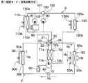
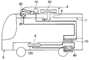
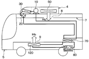
- FIG. 3A, FIG. 4A, FIG. 5A, and FIG. 6A are configuration diagrams showing the configuration of the vehicle air conditioner, and for each air conditioning mode, cool air, hot air blowing, and refrigerant flows Ya, Yb, Yd is shown.
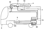
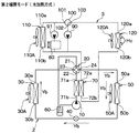
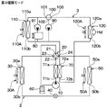
- 2B, FIG. 3B, FIG. 4B, FIG. 5B, and FIG. 6B are layout diagrams of the indoor heat exchangers 50 and 120 in the automobile, and show cool air and hot air blowing for each air conditioning mode.
- 2B, FIG. 3B, FIG. 4B, FIG. 5B, and FIG. 6B are similar to FIG. 1B.
- an arrow Ha indicates cold air blown from the indoor heat exchanger 50
- an arrow Hb indicates hot air blown from the indoor heat exchanger 50
- Arrows Hc and Hd indicate hot air blown out from the indoor heat exchanger 120.
- FIGS. 3A and 3B show the first heating mode
- FIGS. 4A and 4B show the second heating mode
- FIGS. 5A and 5B show the third heating mode
- 6A and 6B show the fourth heating mode.
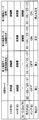
- FIG. 7 shows the operating states of the indoor heat exchanger 50, the outdoor heat exchanger 30, the water refrigerant condenser 70, and the four-way valve 20 for each air conditioning mode, and the outlets that actually blow out cold air and hot air. Show.
- the indoor heat exchanger 50 and the outdoor heat exchanger 30 and the water refrigerant condenser 70 are represented as IHE, XHE, and W / CCnd, respectively, in the drawing.
- “overhead” indicates the indoor heat exchanger 50 and the outlet 8
- “foot” indicates the indoor heat exchanger 120 and the outlet 9.
- the cooling mode First, the cooling mode will be described.
- the electronic control unit 130 controls the electric compressor 10, the four-way valve 20, the electric expansion valve 40, the electric fans 30A, 50A, 110A, 120A, the pumps 90 and 91, and the three-way valve 100, respectively.
- the inlet 22 and the outlet 23 are connected, and the inlet 24 and the outlet 21 are connected.
- the electric compressor 10 sucks and compresses the refrigerant from the gas-liquid separator 60 and discharges the high-temperature and high-pressure refrigerant.
- the high-temperature and high-pressure refrigerant passes through the water refrigerant condenser 70 and the inlet 22 and outlet 23 of the four-way valve 20 and then passes through the outdoor heat exchanger 30, the electric expansion valve 40, and the indoor heat exchanger 50 as indicated by the arrow Ya. It flows in order.
- the outdoor heat exchanger 30 In the outdoor heat exchanger 30, the high-temperature and high-pressure refrigerant radiates heat to the air flow blown from the electric fan 30A. At this time, the outdoor heat exchanger 30 functions as a condenser in which the refrigerant is cooled and condensed by the air flow, as shown in FIG.
- the refrigerant that has passed through the outdoor heat exchanger 30 is decompressed and expanded by the electric expansion valve 40.
- the decompressed and expanded refrigerant cools the air flow blown from the electric fan 50A in the indoor heat exchanger 50.
- the indoor heat exchanger 50 functions as an evaporator that absorbs heat from the air flow and evaporates the refrigerant.
- the cooled air flow passes through the blower duct 7 and then blows out from the plurality of outlets 8 into the vehicle interior as indicated by the arrow Ha in FIG. 2B.
- cold air is blown out from the passenger's head into the passenger compartment.
- the temperature of the indoor heat exchanger 50 is controlled by the electronic control device 130 controlling the refrigerant capacity discharged from the electric compressor 10 and the opening degree of the refrigerant flow path of the electric expansion valve 40. Become. As a result, the room temperature Tr detected by the temperature sensor 140 approaches the set value Tset.
- the refrigerant that has passed through the indoor heat exchanger 50 in FIG. 2A flows through the inlet / outlet 24 and the outlet 21 of the four-way valve 20 and then flows into the gas-liquid separator 60.
- This refrigerant is separated into a gas-phase refrigerant and a liquid-phase refrigerant in the gas-liquid separator 60, and the gas-phase refrigerant is sucked into the electric compressor 10.
- the pump 91 operates. For this reason, the heat medium is circulated between the exhaust heat section of the traveling engine 80 and the radiator 110. For this reason, the heat medium absorbs heat from the combustion chamber at the exhaust heat portion of the traveling engine 80. In radiator 110, the heat medium radiates heat to the air flow blown from electric fan 110A.
- the first heating mode is an air conditioning mode in which an air flow is heated only by the indoor heat exchanger 50 out of the indoor heat exchangers 50 and 120 and blown out from the plurality of outlets 8.
- the control processing of the four-way valve 20 by the electronic control device 130 is different between the first heating mode and the cooling mode.
- the electronic control unit 130 controls the four-way valve 20 to connect the inlet 22 and the outlet 24 and connect the inlet 23 and the outlet 21.
- the high-temperature and high-pressure refrigerant discharged from the electric compressor 10 passes through the water refrigerant condenser 70 and the inlet 22 and the outlet 24 of the four-way valve 20, and then performs indoor heat exchange as indicated by an arrow Yb in FIG. 3A.
- the indoor heat exchanger 50 In the indoor heat exchanger 50, the high-temperature and high-pressure refrigerant heats the air flow blown from the electric fan 50A. At this time, the indoor heat exchanger 50 functions as a condenser in which the refrigerant is cooled and condensed by the air flow, as shown in FIG. For this reason, the air flow (that is, warm air) heated by the high-temperature and high-pressure refrigerant passes through the air duct 7 and then blows out from the plurality of outlets 8 into the vehicle interior as indicated by the arrow Hb in FIG. 3B. That is, warm air is blown out from the passenger's head into the passenger compartment, and the passenger compartment is heated.
- the air flow that is, warm air heated by the high-temperature and high-pressure refrigerant passes through the air duct 7 and then blows out from the plurality of outlets 8 into the vehicle interior as indicated by the arrow Hb in FIG. 3B. That is, warm air is blown out from the passenger's head into
- the temperature of the indoor heat exchanger 50 is controlled by the electronic control device 130 controlling the refrigerant capacity discharged from the electric compressor 10 and the opening degree of the refrigerant flow path of the electric expansion valve 40. Become. As a result, the room temperature Tr detected by the temperature sensor 140 approaches the set value Tset.
- the refrigerant that has passed through the indoor heat exchanger 50 in FIG. 3A is decompressed and expanded by the electric expansion valve 40.
- the decompressed and expanded refrigerant absorbs heat from the air flow blown from the electric fan 50 ⁇ / b> A in the outdoor heat exchanger 30.
- the outdoor heat exchanger 30 functions as an evaporator that absorbs heat from the air flow from the electric fan 50A and evaporates the refrigerant.
- the refrigerant that has passed through the outdoor heat exchanger 30 passes through the inlet / outlet 23 and the outlet 21 of the four-way valve 20 and then flows into the gas-liquid separator 60.
- This refrigerant is separated into a gas-phase refrigerant and a liquid-phase refrigerant in the gas-liquid separator 60, and the gas-phase refrigerant is sucked into the electric compressor 10.
- the second heating mode is an air conditioning mode in which the air flow is heated only by the indoor heat exchanger 120 out of the indoor heat exchangers 50 and 120 and blown out from the plurality of outlets 9.
- the control processing of the pump 90 and the electric fans 120A and 50A by the electronic control device 130 is different between the second heating mode and the first heating mode.
- the electronic control device 130 operates the pump 90.
- the electronic control unit 130 operates the electric fan 120A and stops the electric fan 50A.
- the electronic control unit 130 controls the four-way valve 20 as in the first heating mode. For this reason, in the refrigeration cycle apparatus 2, the refrigerant circulates as in the first heating mode.
- the heat medium pumped by the pump 90 flows and circulates in the order of the water refrigerant condenser 70, the indoor heat exchanger 120, and the pump 90.
- the water refrigerant condenser 70 the high-temperature and high-pressure refrigerant discharged from the electric compressor 10 heats the heat medium. That is, the water refrigerant condenser 70 functions as a condenser in which the refrigerant is cooled and condensed by the heat medium.
- the heat medium heated by the water refrigerant condenser 70 heats the air flow blown from the electric fan 120A.
- the airflow (that is, warm air) heated by the heat medium is blown out from the plurality of air outlets 9 into the vehicle interior as indicated by an arrow Hc in FIG. 4B. That is, warm air is blown out from the feet of the passengers into the passenger compartment.
- the electronic control device 130 controls the refrigerant capacity discharged from the electric compressor 10 and the opening degree of the refrigerant flow path of the electric expansion valve 40, so that the temperature of the water refrigerant condenser 70 and the indoor heat exchanger 120 is adjusted. Will be controlled. As a result, the room temperature Tr detected by the temperature sensor 140 approaches the set value Tset.
- the third heating mode is an air conditioning mode that combines the first heating mode and the second heating mode.
- the main difference between the third heating mode and the second heating mode is that the electric fans 120A and 50A are operated by the electronic control unit 130, respectively.
- the air flow blown from the electric fan 120A is heated by the heat medium that has passed through the water refrigerant condenser 70 as in the second heating mode. For this reason, the airflow (that is, warm air) heated by the heat medium is blown out from the plurality of outlets 9 into the vehicle interior as indicated by an arrow Hb in FIG. 5B.
- the air flow blown from the electric fan 50A is heated by the high-temperature and high-pressure refrigerant as in the first heating mode. For this reason, the air flow heated by the high-temperature and high-pressure refrigerant (that is, warm air) passes through the air duct 7 and then blows out from the plurality of air outlets 8 into the vehicle interior as indicated by the arrow Hb in FIG. 5B.
- the high-temperature and high-pressure refrigerant that is, warm air
- the water refrigerant condenser 70 and the indoor heat exchanger 50 function as a condenser in which the refrigerant is cooled and condensed by the air flow, as shown in FIG.
- the electronic control unit 130 controls the electric fans 120A and 50A to reduce the amount of air blown from the electric fan 120A compared to the amount of air blown from the electric fan 50A.
- the warm air temperature which blows off from the several blower outlet 9 can be made higher than the warm air temperature which blows off from the several blower outlet 8. FIG. For this reason, the feeling given to the passenger can be improved.
- (4th heating mode) In the fourth heating mode, the electric compressor 10 is stopped, the heat medium is heated by the exhaust heat of the combustion chamber of the traveling engine 80, the air flow is heated by the heated heat medium, and the vehicle is It is an air conditioning mode that blows out indoors.
- the electronic control unit 130 controls the three-way valve 100 to connect only the outlet 101 and the inlet 103 among the outlets 101 and 102. For this reason, with the operation of the pump 91, the heat medium from the pump 91 is heated by the exhaust heat portion of the traveling engine 80, and a part of the heated heat medium is the radiator 110, It flows in the order of the pump 91. In radiator 110, the heat medium is cooled by the air flow blown from electric fan 110A.
- the remaining heat medium other than a part of the heat medium that has flowed to the water inlet 110b side of the radiator 110 is the water refrigerant condenser 70, the indoor heat exchanger. 120, the three-way valve 100, and the pump 91 flow in this order.
- the indoor heat exchanger 120 the airflow blown from the electric fan 120A is heated by the heat medium and blown out from the plurality of outlets 9 into the vehicle interior as indicated by the arrow Hd in FIG. 6B. That is, warm air is blown out from the feet of the passengers into the passenger compartment.
- the cooling mode and the first to fourth heating modes are performed.
- the fourth heating mode is set. carry out. Thereby, the vehicle interior can be heated by effectively using the exhaust heat of the traveling engine 80.
- the electronic control device 130 determines that the temperature of the heat medium in the exhaust heat section of the traveling engine 80 is lower than a predetermined temperature based on the output signal of the water temperature sensor 141, the first heating mode and the second heating mode are performed. Any one of the mode and the third heating mode is performed.
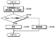
- FIG. 8 is a flowchart showing the selection process in the electronic control unit 130.
- FIG. 9 is a flowchart showing details of step S130 in FIG.
- the electronic control device 130 executes a computer program stored in advance in the memory according to the flowcharts of FIGS.
- step S100 the set value Tset set by the operation panel 142 and the room temperature Tr detected by the temperature sensor 140 are read.
- step S110 it is determined whether or not the difference Tset ⁇ Tr between the set value Tset and the room temperature Tr is larger than the threshold value A.
- the electronic control device 130 corresponds to the capability determination unit by executing step S110.
- the difference Tset ⁇ Tr indicates the heating capacity necessary for heating the vehicle interior by the indoor heat exchangers 50 and 120.
- the heating capacity increases as the difference Tset-Tr increases.
- the heating capacity is an ability to transfer heat from the indoor heat exchangers 50 and 120 to the air flow.
- the difference Tset ⁇ Tr is larger than the threshold value A.
- the heating capacity necessary for heating the passenger compartment becomes larger than a predetermined value, and the electronic control unit 130 determines YES in step S110.
- step S120 the electronic control unit 130 performs the third heating mode in which hot air is blown out using the indoor heat exchangers 120 and 50 together.
- Warm-up is an excessive state from the start of the control until the steady state is reached in the air conditioning control in the passenger compartment.
- the electronic control unit 130 determines NO in step S110, assuming that the heating capacity necessary for heating the passenger compartment is equal to or less than a predetermined value. Accordingly, in step S130, the electronic control unit 130 performs a normal process and performs one of the first heating mode and the second heating mode.
- step S131 of FIG. 9 it is determined whether or not the power consumption P consumed by the electric compressor 10 for heating the passenger compartment is larger than the threshold value B.
- the power consumption P is, for example, power consumption when it is assumed that the second heating mode is performed.
- the power consumption P is positively correlated with the electric energy Ed consumed by the electric compressor 10 for heating the passenger compartment.
- the electronic control unit 130 determines whether or not the electrical energy Ed is greater than the second threshold value.
- the power consumption P is obtained based on the difference Tset ⁇ Tr. As the difference Tset-Tr increases, the power consumption P increases.
- the second threshold corresponds to the reference value.
- step S131 when the power consumption P is greater than the threshold value B, the electronic control device 130 determines that the electrical energy Ed is greater than the second threshold value and determines YES. In this case, the electronic control unit 130 performs the first heating mode in step S132. As a result, the vehicle interior is heated by the air heating type indoor heat exchanger 50.
- step S131 when the power consumption P is equal to or less than the threshold value B, the electronic control device 130 determines NO, assuming that the electric energy Ed is equal to or less than the second threshold value. In this case, the electronic control unit 130 performs the second heating mode in step S133. Thereby, the vehicle interior is heated by the water heating type indoor heat exchanger 120.
- the vehicle air conditioner 1 includes the indoor heat exchanger 50 that heats the air flow blown from the electric fan 50A by the high-temperature and high-pressure refrigerant discharged from the electric compressor 10, and And a water refrigerant condenser 70 that heats a heat medium that absorbs heat from the combustion chamber of the engine 80 with a high-temperature and high-pressure refrigerant.
- the vehicle air conditioner 1 includes an indoor heat exchanger 120 that heats an air flow blown from the electric fan 120 ⁇ / b> A by a heat medium heated by the water refrigerant condenser 70.
- the plurality of air outlets 8 are arranged on the ceiling side of the automobile 5 and open toward the vehicle interior.
- the plurality of air outlets 9 are arranged on the floor side in the passenger compartment and blow out warm air to the feet of the passengers.
- the electronic control unit 130 switches one heating mode between the first heating mode and the second heating mode from the other heating mode.
- the first heating mode is an air conditioning mode in which the air flow is heated only by the indoor heat exchanger 50 out of the indoor heat exchangers 50 and 120 and blown out from the outlet 8. For this reason, the first heating mode can prioritize efficiency over feeling.
- the second heating mode is an air conditioning mode in which the air flow is heated only by the indoor heat exchanger 120 out of the indoor heat exchangers 50 and 120 and blown out from the outlet 9. In the second heating mode, the feeling can be prioritized over the efficiency.
- the vehicle air conditioner 1 can achieve both efficiency and feeling.
- the first heating mode in order to improve the feeling to some extent, it is possible to lower the temperature of the air blown from the air outlet 8 and increase the air volume from the air outlet 8.
- the second heating mode although the temperature at the air outlet 9 can be increased, the air volume from the air outlet 8 cannot be increased in order to increase the air temperature. For this reason, by switching between the first heating mode and the second heating mode, heating can be performed by combining the advantages of the first and second heating modes such as the blowing temperature and the air volume.
- the inventor has studied a system including a refrigeration cycle apparatus that heats hot water using a high-temperature and high-pressure refrigerant discharged from a compressor and a combustor that heats hot water using exhaust heat in a vehicle air conditioner.
- the inventor has studied to preferentially operate one having higher efficiency among the refrigeration cycle apparatus and the combustor when generating hot water used for heating in this system.
- the water heating type heat pump system that heats the air in the passenger compartment with the heat medium requires a water refrigerant condenser that heats the heat medium with the refrigerant.
- the number of heat exchangers is the same as in the case of the water heating type heat pump system, and there are few changes in the configuration of the water heating type heat pump system. For this reason, the vehicle air conditioner 1 of this embodiment can be implemented easily.
- the electronic control device 130 stops the pump 90 when the first heating mode is performed. Therefore, when the first heating mode is performed, the flow of the heat medium through the water refrigerant condenser 70 is stopped. Thereby, it is possible to prevent the heat of the refrigerant from being transmitted to the heat medium in the water refrigerant capacitor 70 in advance.
- the pump 90 since the pump 90 is operated when the second heating mode is performed, the water refrigerant condenser 70 can heat the heat medium favorably with the refrigerant.
- the heat of the refrigerant in the first heating mode, the heat of the refrigerant is directly transmitted to the air in the vehicle interior, whereas in the second heating mode, the heat of the refrigerant is transmitted to the air in the vehicle interior via the heat medium.
- 2nd heating mode has much residual energy compared with 1st heating mode, and its efficiency is low.
- the electric energy given to the electric compressor 10 to drive the electric compressor 10 is referred to as electric energy Ed
- the heat energy output from the indoor heat exchangers 50 and 120 to the air in the passenger compartment is referred to as heat energy Em.
- the efficiency is the ratio En / Em of the thermal energy Em to the electrical energy Ed.
- the amount of heat output from the indoor heat exchanger 50 to the air flow may be the same as the amount of heat output from the indoor heat exchanger 120 to the air flow.
- the electric energy for driving the electric compressor 10 in the second heating mode is larger than the electric energy for driving the electric compressor 10 in the first heating mode.
- the electronic control device 130 performs the first heating mode when the power consumption P is equal to or greater than the first threshold, and performs the second heating mode when the power consumption P is less than the first threshold. .
- the electrical energy consumed in the first heating mode can be brought closer to the electrical energy consumed in the second heating mode. Therefore, the electric energy consumed by the 1st heating mode and the 2nd heating mode can be averaged.
- the air flow is heated by both of the indoor heat exchangers 50 and 120 and the plurality of outlets 9 and the plurality of outlets are heated. Blow out from outlet 8. For this reason, the air temperature in the passenger compartment can be increased in a short time.
- the refrigerant inlet 71b of the water refrigerant condenser 70 is connected to the refrigerant outlet of the electric compressor 10, and the refrigerant outlet 71a of the water refrigerant condenser 70 is connected to the inlet 22 of the four-way valve 20. Therefore, either the cooling mode or the first to fourth heating modes can be performed without using an opening / closing valve other than the four-way valve 20 and without greatly changing the configuration of the refrigerant circuit.
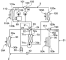
- FIG. 10 shows a configuration of the vehicle air conditioner 1 of the present embodiment.
- the bypass refrigerant flow path 51 is disposed in parallel with the indoor heat exchanger 50 between the inlet / outlet 24 of the four-way valve 20 and the electric expansion valve 40.
- the bypass refrigerant flow path 51 is a refrigerant flow path for bypassing the indoor heat exchanger 50 and flowing the refrigerant flowing through the electric expansion valve 40 from the inlet / outlet 30 b of the outdoor heat exchanger 30 to the inlet / outlet 24 of the four-way valve 20.
- the three-way valve 150 includes a valve mechanism having inlets and outlets 151 and 152 and an outlet 153.
- the valve mechanism is driven by an electric actuator (not shown) to connect the outlet 153 to one of the inlets and outlets 151 and 152. This is a well-known electric switching valve.
- the entrance / exit 151 is an entrance / exit that serves both as an outlet and an inlet for the refrigerant, and is connected to the entrance / exit 24 of the four-way valve 20.
- the entrance / exit 152 is an entrance / exit that serves as both an exit and an entrance for the refrigerant, and is connected to the refrigerant entrance / exit 50a of the indoor heat exchanger 50.
- the outlet 153 is connected to the bypass refrigerant channel 51.
- the electronic control unit 130 controls the four-way valve 20, the pumps 90 and 91, the three-way valve 100, and the like other than the three-way valve 150 in the same manner as in the first embodiment. Therefore, the control of the three-way valve 150 will be mainly described in the cooling mode and the first to third heating modes.
- the electronic control unit 130 controls the three-way valve 150 in the cooling mode to connect only the entrance / exit 152 of the entrance / exit 152 and the exit 153 to the entrance / exit 151. Accordingly, the three-way valve 150 allows the refrigerant to flow into the indoor heat exchanger 50 and prohibits the refrigerant from flowing into the bypass refrigerant flow path 51.
- the refrigerant discharged from the electric compressor 10 passes through the water refrigerant condenser 70, the inlet 22 of the four-way valve 20, and the inlet / outlet 23 of the four-way valve 20 in this order.
- the refrigerant is the outdoor heat exchanger 30, the electric expansion valve 40, the indoor heat exchanger 50, the inlet / outlet 152 of the three-way valve 150, the inlet / outlet 151 of the three-way valve 150, the inlet / outlet 24 of the four-way valve 20, the outlet 21 of the four-way valve 20, It flows in the order of the gas-liquid separator 60 and the refrigerant inlet of the electric compressor 10.
- the electronic control unit 130 controls the three-way valve 150 to connect only the entrance / exit 152 and the entrance / exit 151 out of the entrance / exit 152 and the exit 153 in the first heating mode.
- the refrigerant discharged from the electric compressor 10 passes through the water refrigerant condenser 70, the inlet 22 of the four-way valve 20, and the inlet / outlet 24 of the four-way valve 20 in this order. Thereafter, the refrigerant is the inlet / outlet 151 of the three-way valve 150, the inlet / outlet 152 of the three-way valve 150, the indoor heat exchanger 50, the electric expansion valve 40, the outdoor heat exchanger 30, the inlet / outlet 23 of the four-way valve 20, the outlet 21 of the four-way valve 20, It flows in the order of the gas-liquid separator 60 and the refrigerant inlet of the electric compressor 10.
- the electronic control unit 130 controls the three-way valve 150 in the second heating mode to connect only the outlet 153 and the inlet / outlet 151 out of the inlet / outlet 152 and the outlet 153. Accordingly, the three-way valve 150 prohibits the refrigerant from flowing into the indoor heat exchanger 50 and allows the refrigerant to flow into the bypass refrigerant flow path 51.
- the refrigerant discharged from the electric compressor 10 passes through the water refrigerant condenser 70, the inlet 22 of the four-way valve 20, and the inlet / outlet 24 of the four-way valve 20 in this order. Thereafter, the refrigerant is the inlet 151 of the three-way valve 150, the outlet 153 of the three-way valve 150, the bypass refrigerant flow path 51, the electric expansion valve 40, the outdoor heat exchanger 30, the inlet / outlet 23 of the four-way valve 20, the outlet 21 of the four-way valve 20, It flows in the order of the gas-liquid separator 60 and the refrigerant inlet of the electric compressor 10.
- the electronic control unit 130 controls the three-way valve 150 in the third heating mode, similarly to the first heating mode of the present embodiment. For this reason, the refrigerant
- the electronic control unit 130 controls the three-way valve 150 in the second heating mode to connect only the outlet 153 and the inlet / outlet 151 out of the inlet / outlet 152 and the outlet 153. For this reason, the refrigerant discharged from the electric compressor 10 passes through the water refrigerant condenser 70, the inlet 22 of the four-way valve 20, and the inlet / outlet 24 of the four-way valve 20 in this order. Thereafter, the refrigerant passes through the inlet / outlet 151 of the three-way valve 150 and the outlet 153 of the three-way valve 150 in this order, and then flows to the electric expansion valve 40 side, bypassing the indoor heat exchanger 50.
- the refrigerant discharged from the electric compressor 10 bypasses the indoor heat exchanger 50 and flows toward the electric expansion valve 40 as described above. For this reason, in the indoor heat exchanger 50, it is possible to prevent the refrigerant from radiating heat to the air flow generated by natural convection.
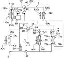
- FIG. 11 shows the configuration of the vehicle air conditioner 1 of the present embodiment.
- the arrangement of the water refrigerant condenser 70 is different from that of the refrigeration cycle apparatus 2 of the above embodiment, and on-off valves 52 and 73 are added.
- the on-off valve 52 is a second on-off valve that is disposed between the inlet / outlet 24 of the four-way valve 20 and the electric expansion valve 40 and opens and closes the refrigerant flow path 53. More specifically, the on-off valve 52 may be disposed between the inlet / outlet 24 of the four-way valve 20 and the refrigerant inlet / outlet 50 a of the indoor heat exchanger 50.
- the refrigerant channel 53 is a channel through which the refrigerant flows between the inlet / outlet 24 of the four-way valve 20 and the electric expansion valve 40, and is arranged in series with the indoor heat exchanger 50.
- the on-off valve 73 is a first on-off valve that is disposed between the inlet / outlet 24 of the four-way valve 20 and the electric expansion valve 40 and opens and closes the refrigerant flow path 74. More specifically, the on-off valve 73 may be disposed between the inlet / outlet 24 of the four-way valve 20 and the refrigerant inlet 71 b of the water refrigerant condenser 70.
- the refrigerant channel 74 is a channel through which the refrigerant flows between the inlet / outlet 24 of the four-way valve 20 and the electric expansion valve 40, and is arranged in series with the water refrigerant capacitor 70.
- the refrigerant flow paths 53 and 74 are arranged in parallel between the inlet / outlet port 24 of the four-way valve 20 and the electric expansion valve 40.
- the on-off valves 52 and 73 for example, electromagnetic valves or electric valves can be used.
- the refrigerant inlet 71b of the water refrigerant condenser 70 is connected to the inlet / outlet 24 of the four-way valve 20, and the refrigerant outlet 71a of the water refrigerant condenser 70 is connected to the electric expansion valve 40.
- the electronic control device 130 controls the four-way valve 20, the pumps 90 and 91, the three-way valve 100, and the like other than the on-off valves 52 and 73 in the same manner as the first embodiment. Therefore, the control of the on-off valves 52 and 73 will be mainly described in the cooling mode and the first to third heating modes.
- the electronic control unit 130 opens the refrigerant channel 53 by the on-off valve 52 and closes the refrigerant channel 74 by the on-off valve 73.
- the refrigerant discharged from the electric compressor 10 passes through the inlet 22 of the four-way valve 20 and the inlet / outlet 23 of the four-way valve 20 in this order.
- the refrigerant is the outdoor heat exchanger 30, the electric expansion valve 40, the indoor heat exchanger 50, the on-off valve 52, the refrigerant flow path 53, the inlet / outlet 24 of the four-way valve 20, the outlet 21 of the four-way valve 20, and the gas-liquid separator 60.
- the refrigerant flows in the order of the refrigerant inlet of the electric compressor 10. For this reason, heat exchange is performed between the refrigerant and the air flow in the indoor heat exchanger 50.
- the electronic control unit 130 controls the on-off valves 52 and 73 in the first heating mode, similarly to the cooling mode of the present embodiment.
- the refrigerant discharged from the electric compressor 10 passes through the inlet 22 of the four-way valve 20 and the inlet / outlet 24 of the four-way valve 20 in this order. Thereafter, the refrigerant is the on-off valve 52, the refrigerant flow path 53, the indoor heat exchanger 50, the electric expansion valve 40, the outdoor heat exchanger 30, the inlet / outlet port 23 of the four-way valve 20, the outlet port 21 of the four-way valve 20, and the gas-liquid separator 60.
- the refrigerant flows in the order of the refrigerant inlet of the electric compressor 10. For this reason, heat exchange is performed between the refrigerant and the air flow in the indoor heat exchanger 50.
- the electronic control unit 130 closes the refrigerant flow path 53 by the opening / closing valve 52 and opens the refrigerant flow path 74 by the opening / closing valve 73.
- the refrigerant discharged from the electric compressor 10 passes through the inlet 22 of the four-way valve 20 and the inlet / outlet 24 of the four-way valve 20 in this order.
- the refrigerant is the on-off valve 73, the refrigerant flow path 74, the refrigerant inlet 71b of the water refrigerant condenser 70, the refrigerant outlet 71a of the water refrigerant condenser 70, the electric expansion valve 40, the outdoor heat exchanger 30, the inlet / outlet 23 of the four-way valve 20, It flows in the order of the outlet 21 of the four-way valve 20, the gas-liquid separator 60, and the refrigerant inlet of the electric compressor 10. For this reason, heat exchange is performed between the refrigerant and the heat medium in the water refrigerant condenser 70.
- the electronic control unit 130 opens the refrigerant flow path 53 by the opening / closing valve 52 and opens the refrigerant flow path 74 by the opening / closing valve 73.
- some of the refrigerant discharged from the electric compressor 10 through the inlet 22 and the inlet / outlet 24 of the four-way valve 20 includes the on-off valve 73, the refrigerant flow path 74, the refrigerant inlet 71b of the water refrigerant condenser 70, the water refrigerant. It flows in the order of the refrigerant outlet 71a of the condenser 70 and the electric expansion valve 40.
- the remaining refrigerant other than a part of the refrigerant flowing toward the on-off valve 73 side includes the on-off valve 52, the refrigerant flow path 53, It flows in the order of the indoor heat exchanger 50 and the electric expansion valve 40.
- the electronic control unit 130 can control the four-way valve 20 and the on-off valves 52 and 73 to perform any one of the cooling mode and the first to fourth heating modes.
- the on-off valve 73 closes the refrigerant flow path 74 in the first heating mode, it is possible to prevent the refrigerant from being circulated wastefully between the electric compressor 10 and the water refrigerant condenser 70. For this reason, the water refrigerant condenser 70 can prevent the refrigerant from heating the heat medium wastefully.
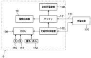
- FIG. 12 shows the electrical configuration of the automobile 5 of the present embodiment.
- the automobile 5 includes a battery 161 and a control device 162 for charge control.
- the battery 161 is a high voltage battery that supplies electric power to the electric motor 160 for traveling and the electric compressor 10.
- the charging control device 162 performs control for charging the battery 161 by the charging device 170 via communication with the charging device 170.
- the charging device 170 is installed in a parking lot or a garage, and includes a charging cable 171.
- the charging cable 171 is used to connect the automobile 5 and supply power to the battery 161. Communication between the charging control device 162 and the charging device 170 is performed via a wiring in the charging cable 171 or the like.
- the traveling motor 160 is an electric motor that applies driving force to the driving wheels.
- the electronic control device 130 of the present embodiment performs a pre-air conditioning control process that implements the first heating mode as pre-air conditioning based on a communication signal from the charging control device 162.
- the communication signal from the charging control device 162 includes information on whether or not the battery 161 is being charged by the charging device 170.
- the pre-air conditioning is to air-condition the passenger compartment before the occupant gets into the automobile 5.
- a timer setting unit for setting a pre-air-conditioning implementation time zone that is, a start time and an end time
- FIG. 13 is a flowchart showing the pre-air conditioning control process of the electronic control device 130.
- the electronic control device 130 executes pre-air conditioning control processing according to the flowchart of FIG.
- step S ⁇ b> 200 the electronic control device 130 determines whether or not the battery 161 is being charged by the charging device 170 based on the communication signal from the charging control control device 162.
- the electronic control device 130 corresponds to the charge determination unit by executing step S200.
- step S200 the electronic control device 130 determines that the battery 161 is not charged by the charging device 170 based on the communication signal from the charging control device 162 and determines NO in step S200.
- step S200 the electronic control device 130 repeats the NO determination in step S200. Thereafter, when charging of battery 161 by charging device 170 is started, electronic control device 130 determines YES in step S200.
- the electronic control unit 130 determines whether or not pre-air conditioning is requested. Specifically, it is determined whether or not the current time is in the pre-air-conditioning implementation time zone set by the timer setting unit of the operation panel 142.
- the electronic control device 130 corresponds to the request determination unit by executing step S210.
- step S210 determines NO in step S210 because pre-air-conditioning is not requested. . Then, the electronic control unit 130 returns to step S210. For this reason, as long as the current time is out of the pre-air conditioning implementation time zone, the electronic control device 130 repeats the NO determination in step S210.
- the electronic control unit 130 determines YES in step S210 because pre-air-conditioning is requested.
- step S220 the electronic control unit 130 performs the first heating mode using the air heating type indoor heat exchanger 50 as pre-air conditioning.
- step S200 the electronic control unit 130 returns to step S200. After that, as long as it is determined that the battery 161 is being charged by the charging device 170 and pre-air conditioning is required, the YES determination in step S200, the YES determination in step S210, and the first heating mode are repeated. .
- the electronic control device 130 when it is determined that the battery 161 is being charged by the charging device 170 and pre-air conditioning is required, the electronic control device 130 performs the first heating mode and performs pre-air conditioning. I do. Thereby, heating of the vehicle interior with high efficiency can be performed. In this case, since there is no occupant in the vehicle compartment, even if the first heating mode is performed, the deterioration of the feeling given to the occupant does not matter.
- the electronic control apparatus 130 demonstrated the example which implemented 1st heating mode in step S220. However, instead of this, the electronic control unit 130 may perform the third heating mode in which the indoor heat exchangers 120 and 50 are used in combination in step S220. Thereby, the air temperature in a vehicle interior can be raised in a short time.
- the vehicle air conditioner 1 of the first embodiment may be applied to an electric vehicle including only the traveling motor 160 among the traveling engine 80 and the traveling motor 160.
- the electronic control unit 130 detects the number of occupants, and when the detected number of occupants is less than the predetermined number, the first heating mode is performed, and the occupant When the number of persons is equal to or greater than the predetermined number, the second heating mode may be performed.
- a sensor for detecting the number of occupants for example, a seating sensor for detecting whether or not the occupant has been seated may be used.
- the electronic control unit 130 can be operated in any one of the cooling mode, the first, second, third, and fourth heating modes by operating the operation panel 142. May be selected and executed.
- a predetermined value may be used. Alternatively, it may be changed according to various kinds of information as in the following (6-1) (6-2) (6-3) (6-4).
- a sensor that detects the remaining amount of fuel in a fuel tank that accumulates fuel such as gasoline or light oil used in the traveling engine 80 may be employed.
- the electronic control unit 130 may decrease the threshold B as the remaining amount of fuel detected by the sensor decreases. Thereby, with the decrease in the fuel in the fuel tank, the first heating mode is more easily performed than the second heating mode.
- a sensor that detects electric power stored in a battery that supplies electric power to the electric compressor 10 may be employed.
- the electronic control unit 130 may decrease the threshold B as the electric power detected by the sensor decreases.
- the 1st heating mode becomes easy to be implemented compared with the 2nd heating mode with the reduction of the electric power stored in the battery.
- (6-3) A navigation device that searches for a route from the current position to the target position may be adopted.
- the electronic control unit 130 may predict the energy required for traveling the automobile 5 based on the road information of the route searched by the navigation device, and may decrease the threshold B as the predicted energy increases. . Accordingly, the first heating mode is more easily performed as compared to the second heating mode as the energy required for traveling of the automobile 5 increases.
- the electronic control unit 130 acquires information indicating the weather forecast of the current location of the vehicle from the server via the Internet, etc., and predicts the energy required for air conditioning in the vehicle interior based on the acquired information. Also good. In this case, the electronic control unit 130 may decrease the threshold B as the predicted energy increases. Accordingly, the first heating mode is more easily performed as compared with the second heating mode as the energy required for air conditioning in the passenger compartment increases.
- an on-off valve that opens and closes the heat medium flow path through which the heat medium flows between the pump 90 and the water refrigerant condenser 70 is employed.
- the electronic control unit 130 controls the on-off valve to open the heat medium flow path.
- the electronic control unit 130 controls the on-off valve to close the heat medium flow path.
- step S210 of FIG. 13 is the electronic control device 130 requested for pre-air conditioning based on the pre-air conditioning implementation time zone set by the timer setting unit of the operation panel 142?
- the example of determining whether or not was described. However, instead of this, the following may be used.
- wireless communication is performed between the portable wireless terminal and the electronic control device 130.
- the electronic control device 130 determines whether or not pre-air conditioning is requested by determining whether or not a request signal for requesting pre-air conditioning is received from the portable wireless terminal.
- the vehicle air conditioner 1 may be applied to an automobile other than a bus vehicle, a train, a train, or the like.
- the amount of air blown by the electric fan 120A is made smaller than the amount of air blown by the electric fan 50A, and the hot air temperatures from the plurality of outlets 9 are changed from the plurality of outlets 8 to each other.
- the example which made it higher than warm air temperature was demonstrated. However, instead of this, the following may be used.
- the heating capacity of the water refrigerant condenser 70 is an ability of the refrigerant to transfer heat to the heat medium in the water refrigerant condenser 70.
- the heating capacity of the indoor heat exchanger 50 is an ability of the refrigerant to transfer heat to the air flow in the indoor heat exchanger 50.
- the electronic control device 130 may omit the execution of steps S110 and S120 in the process of FIG. More specifically, the electronic control unit 130 may execute step S130 immediately after step S100.
- the vehicle air conditioner is disposed on the ceiling side in the vehicle interior.
- the present invention is applied to a vehicle that includes one air outlet and a second air outlet that is disposed on the floor side in the passenger compartment.
- the vehicle air conditioner switches between a first blower that blows an air flow, a second blower that blows an air flow, a first indoor heat exchanger, a heating heat exchanger, and a second indoor heat exchanger. And a control unit.
- a 1st indoor heat exchanger comprises the heat pump cycle which circulates a refrigerant
- the air flow ventilated from a 1st air blower is carried out with the refrigerant
- the heat exchanger for heating constitutes a heat pump cycle and heats the heat medium with a refrigerant.
- the second indoor heat exchanger heats the air flow blown from the second blower by the heated heat medium.
- the first air outlet blows out the air flow heated by the first indoor heat exchanger into the vehicle interior, and the second air outlet blows out the air flow heated by the second indoor heat exchanger into the vehicle interior. Is heated.
- the switching control unit heats the air flow only by the first indoor heat exchanger out of the first indoor heat exchanger and the second indoor heat exchanger and blows it out from the first outlet. Switching between the heating mode and the second heating mode in which the air flow is heated only by the second indoor heat exchanger out of the first indoor heat exchanger and the second indoor heat exchanger and blown out from the second outlet is performed.
- the vehicle air conditioner includes a pump that circulates the heat medium between the heating heat exchanger and the second indoor heat exchanger.
- the switching control unit stops the pump when implementing the first heating mode, and operates the pump when implementing the second heating mode.
- the heating heat exchanger can be stopped from heating the heat medium with the refrigerant. Accordingly, it is possible to prevent the heating heat exchanger from heating the heat medium with the refrigerant when the first heating mode is performed. For this reason, it is possible to prevent the heat of the refrigerant from being transmitted to the heat medium in vain.
- the heat exchanger for heating can heat a heat carrier favorably with a refrigerant.
- the vehicle air conditioner constitutes a heat pump cycle, and includes a first inlet and a second inlet / outlet that serve both as an outlet and an inlet for the refrigerant, and exchanges heat between the refrigerant and air outside the passenger compartment.
- the first indoor heat exchanger includes a first inlet / outlet and a second inlet / outlet that serve both as an inlet and an outlet for the refrigerant.
- the heat exchanger for heating includes a refrigerant inlet into which a refrigerant enters and a refrigerant outlet from which the refrigerant is discharged.
- the four-way valve is connected to the refrigerant suction port of the compressor and has a valve outlet for flowing the refrigerant to the refrigerant suction port of the compressor, and a valve connected to the refrigerant discharge port of the compressor and receiving the refrigerant from the refrigerant discharge port of the compressor
- a second valve inlet / outlet that also serves as a second valve.
- the pressure reducer includes a four-way valve having a valve inlet connected to one of the first valve inlet and the second valve inlet, and a valve outlet connected to the other valve inlet and second outlet of the outdoor heat exchanger.
- the refrigerant flowing between the second inlet / outlet of the outdoor heat exchanger and the second inlet / outlet of the first indoor heat exchanger is decompressed and expanded between the second inlet / outlet of the outdoor heat exchanger and the second inlet / outlet of the first indoor heat exchanger.
- the refrigerant inlet of the heating heat exchanger is connected to the refrigerant outlet of the compressor, and the refrigerant outlet of the heating heat exchanger is connected to the inlet of the four-way valve.
- the refrigerant discharged from the compressor is discharged from the compressor in the outdoor heat exchanger.
- the refrigerant radiates heat to the outdoor air, and in the first indoor heat exchanger, the refrigerant supplied from the outdoor heat exchanger through the decompressor cools the air flow from the first blower.
- the four-way valve inlet and the second valve outlet are connected, and the first valve outlet and the valve outlet are connected.
- the refrigerant discharged from the compressor heats the air flow from the first blower in the first indoor heat exchanger, and the first indoor heat exchanger in the outdoor heat exchanger.
- the refrigerant supplied through the decompressor absorbs heat from the air outside the passenger compartment.
- any one of the cooling mode, the first heating mode, and the second heating mode can be performed by operating the four-way valve without using an on-off valve other than the four-way valve.
- the vehicle air conditioner is disposed between the second valve inlet / outlet of the four-way valve and the pressure reducer and bypasses the first indoor heat exchanger to flow the refrigerant
- a three-way valve disposed between the second valve inlet / outlet of the four-way valve and the pressure reducer to allow refrigerant to flow through one of the first indoor heat exchanger and the bypass refrigerant flow path and prohibit the refrigerant from flowing through the other And a valve.
- the three-way valve In the cooling mode and the first heating mode, the three-way valve allows the refrigerant to flow to the first indoor heat exchanger and prohibits the refrigerant from flowing to the bypass refrigerant flow path.
- the three-way valve prohibits the refrigerant from flowing into the first indoor heat exchanger and allows the refrigerant to flow into the bypass refrigerant flow path.
- the refrigerant in the cooling mode and the first heating mode, since the refrigerant flows through the first indoor heat exchanger, the refrigerant can cool or heat the air flow in the first indoor heat exchanger.
- the second heating mode since the refrigerant is prohibited from flowing through the first indoor heat exchanger, it is possible to prevent the refrigerant from heating the air flow in the first indoor heat exchanger.
- the vehicle air conditioner includes a first inlet and a second inlet / outlet that serve as both a refrigerant outlet and an inlet, constituting a heat pump cycle, and heat exchange between the refrigerant and air outside the passenger compartment.
- the first indoor heat exchanger includes a first inlet / outlet and a second inlet / outlet that serve both as an inlet and an outlet for the refrigerant.
- the heat exchanger for heating includes a refrigerant inlet into which a refrigerant enters and a refrigerant outlet from which the refrigerant is discharged.
- the four-way valve is connected to the refrigerant suction port of the compressor to allow the refrigerant to flow into the refrigerant suction port of the compressor, and the refrigerant from the refrigerant discharge port of the compressor is connected to the refrigerant discharge port of the compressor.
- the valve inlet is connected to one of the first valve inlet / outlet and the second valve inlet / outlet, and the valve outlet is connected to the other valve inlet / outlet.
- the decompressor is disposed between the second inlet / outlet of the outdoor heat exchanger and the second inlet / outlet of the first indoor heat exchanger, and is connected to the second inlet / outlet of the outdoor heat exchanger and the second inlet / outlet of the first indoor heat exchanger. The refrigerant flowing from one to the other is decompressed and expanded.
- the refrigerant inlet of the heating heat exchanger is connected to the second inlet / outlet of the four-way valve, and the refrigerant outlet of the heating heat exchanger is connected to the second inlet / outlet of the outdoor heat exchanger via the decompressor.
- the refrigerant discharged from the compressor through the four-way valve in the outdoor heat exchanger Dissipates heat to the air outside the passenger compartment, and in the first indoor heat exchanger, the refrigerant supplied from the outdoor heat exchanger through the decompressor cools the air flow from the first blower.
- the valve inlet of the four-way valve and the second valve inlet / outlet are connected, and the first valve inlet / outlet of the four-way valve and the valve outlet are connected.
- the refrigerant discharged from the compressor through the four-way valve heats the air flow from the first blower, and in the outdoor heat exchanger, the pressure is reduced from the first indoor heat exchanger.
- the refrigerant supplied through the chamber absorbs heat from the air outside the passenger compartment.
- the valve inlet of the four-way valve and the second valve inlet / outlet are connected, and the first valve inlet / outlet of the four-way valve and the valve outlet are connected.
- the refrigerant discharged from the compressor through the four-way valve heats the heat medium in the heating heat exchanger, and the refrigerant supplied from the first indoor heat exchanger through the decompressor in the outdoor heat exchanger. Absorbs heat from outside the cabin.
- any one of the cooling mode, the first heating mode, and the second heating mode can be performed by operating the four-way valve.
- the vehicle air conditioner includes a first on-off valve that opens and closes a first refrigerant flow path for flowing a refrigerant between the compressor and the heat exchanger for heating, the compressor, and the first indoor heat.
- a second opening / closing valve arranged in parallel to the first refrigerant flow path to open and close the second refrigerant flow path for flowing the refrigerant.
- the first on-off valve closes the first refrigerant flow path, and the second on-off valve opens the second refrigerant flow path. For this reason, it can prevent beforehand that a refrigerant heats a heat carrier in a heat exchanger for heating.
- the first on-off valve opens the first refrigerant flow path, and the second on-off valve closes the second refrigerant flow path. For this reason, it is possible to prevent the refrigerant from heating the air flow in the first indoor heat exchanger.
- the vehicle air conditioner heats the air flow by both the first indoor heat exchanger and the second indoor heat exchanger and blows out the air from the first air outlet and the second air outlet.
- the combination control part which replaces and implements a mode in the 1st heating mode and the 2nd heating mode is provided.
- the air temperature in the passenger compartment can be increased in a short time by performing the third heating mode.
- the vehicle air conditioner determines whether the heating capacity required for the first indoor heat exchanger and the second indoor heat exchanger to heat the vehicle interior is greater than the first threshold value.
- a capability determination unit for determining is provided. When the capacity determination unit determines that the heating capacity is greater than the first threshold, the combined control unit performs the third heating mode.
- the capacity determination unit determines that the heating capacity is larger than the first threshold, the air temperature in the passenger compartment can be increased in a short time.
- the vehicle air conditioner includes an energy determination unit that determines whether or not the energy given to the compressor for heating the vehicle interior is larger than the second threshold value.
- the switching control unit performs the first heating mode.
- the switching control unit performs the second heating mode.
- the heat of the refrigerant is directly transmitted to the air in the vehicle interior, whereas in the second heating mode, the heat of the refrigerant is transmitted to the air in the vehicle interior via the heat medium. For this reason, efficiency is low in the 2nd heating mode compared with the 1st heating mode.
- the compressor is used to perform the second heating mode.
- the energy to be given is larger than the energy given to the compressor in order to implement the first heating mode.
- the energy given to the compressor for heating is larger than the second threshold, the first heating mode is performed, and when the energy given to the compressor for heating is equal to or lower than the second threshold, 2nd heating mode is implemented. For this reason, the energy consumed in the 1st heating mode and the energy consumed in the 2nd heating mode can be brought close. Therefore, energy consumed in the first heating mode and the second heating mode can be averaged.
- the vehicle air conditioner is applied to a vehicle including an electric compressor as a compressor, a traveling motor, and a battery that supplies electric power to the electric compressor and the traveling motor.
- the vehicle air conditioner is required to perform a charge determination unit that determines whether or not the battery is charged by the charging device and pre-air conditioning that heats the passenger compartment before the passenger gets into the passenger compartment.
- a request determination unit that determines whether or not the request exists.
- the vehicle air conditioner is configured such that when the charge determination unit determines that the battery is charged by the charging device and the request determination unit determines that pre-air conditioning is required, the first indoor heat
- the heating setting part which heats an air flow by both an exchanger and a 2nd indoor heat exchanger, and blows off from a 1st blower outlet and a 2nd blower outlet, or the 1st heating mode is provided.
- the air temperature in the passenger compartment can be shortened in a short time. Can be high.
- the efficiency is improved if the first heating mode is performed. For this reason, consumption of electric energy can be suppressed in the electric compressor. Thereby, it can suppress that the electrical energy stored in the battery reduces. Therefore, the charging of the battery can be completed in a short time by the charging device.
- the vehicle air conditioner includes an energy determination unit that determines whether or not the energy given to the compressor for heating the vehicle interior is larger than the reference value. When the energy determination unit determines that the energy is larger than the reference value, the switching control unit performs the first heating mode. When the energy determination unit determines that the energy is equal to or less than the reference value, the switching control unit performs the second heating mode.
- the energy consumed in the first heating mode can be brought closer to the energy consumed in the second heating mode. Therefore, energy consumed in the first heating mode and the second heating mode can be averaged.
Landscapes
- Physics & Mathematics (AREA)
- Thermal Sciences (AREA)
- Engineering & Computer Science (AREA)
- Mechanical Engineering (AREA)
- Air-Conditioning For Vehicles (AREA)
Abstract
車両用空調装置は、車室内の天井側に配置される第1吹出口(8)と床側に配置される第2吹出口(9)とを備える車両に適用される。車両用空調装置は、空気流を送風する第1送風機(50A)、第2送風機(120A)を備える。車両用空調装置は、第1室内熱交換器(50)と、加熱用熱交換器(70)と、第2室内熱交換器(120)と、切替制御部(S131~S133)とを備える。第1吹出口が第1室内熱交換器により加熱された空気流を車室内に吹き出し、第2吹出口が第2室内熱交換器により加熱された空気流を車室内に吹き出すことにより、車室内が暖房される。切替制御部は、車室内を暖房する際に、第1、第2室内熱交換器のうち第1室内熱交換器のみによって空気流を加熱して第1吹出口から吹き出す第1暖房モードと、第1、第2室内熱交換器のうち第2室内熱交換器のみによって空気流を加熱して第2吹出口から吹き出す第2暖房モードとを切り替える。
Description
本出願は、2015年12月15日に出願された日本特許出願番号2015-244321号に基づくもので、ここにその記載内容が参照により組み入れられる。
本開示は、車室内を暖房する車両用空調装置に関するものである。
従来、エンジン冷却水が流れる温水回路に室内熱交換器と水冷媒熱交換器とを設けたヒートポンプシステムを用いた車両用空調装置が、例えば、特許文献1に開示されている。
水冷媒熱交換器は、圧縮機から吐出される高温高圧の冷媒によりエンジン冷却水を加熱する。室内熱交換器は、高温高圧の冷媒により加熱されたエンジン冷却水により車室内の空気を加熱する。これにより、高温高圧の冷媒を用いてエンジン冷却水の温度を急速に上昇させることができる。これに伴って、車室内の空気温度を急速に上昇させることができる。
以下、説明の便宜上、温水回路に室内熱交換器と水冷媒熱交換器とを設けたヒートポンプシステムを水加熱式ヒートポンプシステムという。
上記特許文献1の水加熱式ヒートポンプシステムでは、上述の如く、車室内の空気温度を急速に上昇させることができるものの、空気を加熱するために水冷媒熱交換器および室内熱交換器が必要となる。このため、圧縮機から冷媒に出力される熱エネルギをエンジン冷却水を通して空気に伝達することが必要になる。
この場合、冷媒とエンジン冷却水の間で熱交換され、かつエンジン冷却水と空気の間で熱交換される。したがって、圧縮機から冷媒に出力される熱エネルギのうち一部の熱エネルギが、空気に伝わることなく、冷媒やエンジン冷却水に残留する。以下、このように、圧縮機から冷媒に出力された熱エネルギのうち、冷媒やエンジン冷却水に残留する熱エネルギを残留熱エネルギという。
また、圧縮機から吐出される冷媒によって直接空気を加熱する室内熱交換器を備えるヒートポンプシステムが考えられる。以下、このようなヒートポンプシステムを空気加熱式ヒートポンプシステムという。この空気加熱式ヒートポンプシステムでは、冷媒と空気の間で熱交換されて、冷媒に熱エネルギが残留するものの、水加熱式ヒートポンプシステムに比べて、残留熱エネルギが少ない。
つまり、水加熱式ヒートポンプシステムは、空気加熱式ヒートポンプシステムに比べて、残留熱エネルギが多く、効率が低くなる。このため、効率を考えると、空気加熱式ヒートポンプシステムが良い。効率とは、圧縮機を駆動するために圧縮機に与えるエネルギをエネルギEaとし、室内熱交換器から車室内の空気に出力される熱エネルギを熱エネルギEnとしたときに、エネルギEaに対する熱エネルギEnの比率En/Eaである。
ここで、バス等の車室内の空調に用いる空気加熱式ヒートポンプシステムとしては、四方弁等により冷媒流れを切り替えて室内熱交換器を冷房と暖房とで共用する冷凍サイクルを採用するものがある。このような空気加熱式ヒートポンプシステムでは、室内熱交換器を車室内の天井側に配置することが一般的である。
しかし、空気加熱式ヒートポンプシステムにおいて、室内熱交換器を車室内の天井側に配置して暖房を行うと、効率が良くなるが、乗員に与えるフィーリングが悪くなる。
一般的に、頭部を冷たくして、足部を暖かくする空調を実施して、暖房時に乗員に与えるフィーリングを良好にすることが知られている。このため、上述の如く、室内熱交換器を車室内の天井側に配置して乗員の頭上から単に温風を吹き出すだけでは、乗員に与えるフィーリングが悪くなる。
本開示は上記点に鑑みて、効率とフィーリングとを両立させるようにした車両用空調装置を提供することを目的とする。
本開示の1つの観点によれば、車両用空調装置は、車室内の天井側に配置されている第1吹出口と、車室内の床側に配置されている第2吹出口とを備える車両に適用される。車両用空調装置は、
空気流を送風する第1送風機と、
空気流を送風する第2送風機と、
冷媒を吸入して圧縮して吐出する圧縮機とともに、冷媒を循環させるヒートポンプサイクルを構成し、第1送風機から送風される空気流を圧縮機から吐出される冷媒により加熱する第1室内熱交換器と、
上記ヒートポンプサイクルを構成し、熱媒体を冷媒により加熱する加熱用熱交換器と、
加熱された熱媒体により第2送風機から送風される空気流を加熱する第2室内熱交換器と、
切替制御部と、を備える。
空気流を送風する第1送風機と、
空気流を送風する第2送風機と、
冷媒を吸入して圧縮して吐出する圧縮機とともに、冷媒を循環させるヒートポンプサイクルを構成し、第1送風機から送風される空気流を圧縮機から吐出される冷媒により加熱する第1室内熱交換器と、
上記ヒートポンプサイクルを構成し、熱媒体を冷媒により加熱する加熱用熱交換器と、
加熱された熱媒体により第2送風機から送風される空気流を加熱する第2室内熱交換器と、
切替制御部と、を備える。
第1吹出口が第1室内熱交換器により加熱された空気流を車室内に吹き出し、第2吹出口が第2室内熱交換器により加熱された空気流を車室内に吹き出すことにより、車室内が暖房される。
前記切替制御部は、車室内を暖房する際に、第1室内熱交換器および第2室内熱交換器のうち第1室内熱交換器のみによって空気流を加熱して第1吹出口から吹き出す第1暖房モードと、第1室内熱交換器および第2室内熱交換器のうち第2室内熱交換器のみによって空気流を加熱して第2吹出口から吹き出す第2暖房モードとを切り替えて実施する。
これによれば、第1暖房モードは、第1室内熱交換器および第2室内熱交換器のうち第1室内熱交換器のみによって空気流を加熱して第1吹出口から吹き出すため、フィーリングよりも効率を優先させることができる。一方、第2暖房モードは、第1室内熱交換器および第2室内熱交換器のうち第2室内熱交換器のみによって空気流を加熱して第2吹出口から吹き出すため、効率よりもフィーリングを優先させることができる。このため、切替制御部が第1暖房モードおよび第2暖房モードを切り替えて実施することにより、フィーリングよりも効率を優先させる期間と、効率よりもフィーリングを優先させる期間とを切り替えることができる。したがって、車両用空調装置において、効率とフィーリングとを両立させることができる。
ここで、熱媒体とは、熱を移動させるために用いられる流体である。
以下、本開示の実施形態について図に基づいて説明する。なお、以下の各実施形態相互において、互いに同一もしくは均等である部分には、説明の簡略化を図るべく、図中、同一符号を付してある。
(第1実施形態)
図1Aは、第1実施形態における車両用空調装置1の構成を示す構成図である。図1Bは、第1実施形態における自動車5内の室内熱交換器50、120等の配置図である。
図1Aは、第1実施形態における車両用空調装置1の構成を示す構成図である。図1Bは、第1実施形態における自動車5内の室内熱交換器50、120等の配置図である。
車両用空調装置1は、例えばバス車両等の自動車5に搭載される。車両用空調装置1は、車室内の空調を行うものであって、冷凍サイクル装置2、および温水回路3から構成されている。
冷凍サイクル装置2は、冷媒を循環させて吸熱と放熱とを繰り返すヒートポンプサイクルを構成するものであって、四方弁20によって冷媒の流れを切り替えて冷房と暖房とを切り替える。このヒートポンプサイクルは、蒸気圧縮式の冷凍サイクルである。
具体的には、冷凍サイクル装置2は、冷媒配管によって閉回路を構成する。冷凍サイクル装置2は、電動圧縮機10、四方弁20、室外熱交換器30、電動膨張弁40、室内熱交換器50、気液分離器60、水冷媒コンデンサ70、および電動ファン30A、50Aを備える。
電動圧縮機10は、冷媒を吸入して圧縮して吐出する圧縮機構と、この圧縮機構を駆動する電動モータとから構成されている。
四方弁20は、出口21、入口22、および出入口23、24を有する弁機構を備え、不図示の電動アクチュエータにより弁機構を駆動して出入口23、24のうちいずれか一方の出入口に入口22を接続し、他方の出入口に出口21を接続する。
出口21は、気液分離器60を介して電動圧縮機10の冷媒吸入口に接続されている弁出口である。入口22は、水冷媒コンデンサ70を介して電動圧縮機10の冷媒吐出口に接続されている弁入口である。出入口23は、室外熱交換器30の出入口30aに接続されて冷媒の入口と出口とを兼ねる第1弁出入口である。出入口24は、室内熱交換器50の冷媒出入口50aに接続されて冷媒の入口と出口とを兼ねる第2弁出入口である。
室外熱交換器30は、電動ファン30Aから送風される車室外の空気と冷媒との間で熱交換する。以下、車室外の空気を外気とし、車室内の空気を内気とする。室外熱交換器30は、冷媒の入口と出口とを兼ねる出入口30a、30bを備える。出入口30aは、四方弁20の出入口23に接続されて冷媒の入口と出口とを兼ねる第1出入口である。出入口30bは、冷媒の入口と出口とを兼ねる第2出入口であって、室内熱交換器50の第2出入口50bに電動膨張弁40を介して接続されている。
電動膨張弁40は、室外熱交換器30と室内熱交換器50の間に配置されて、室外熱交換器30と室内熱交換器50の間の冷媒流路の開度を電動アクチュエータにより調整する減圧器である。冷媒流路は、室外熱交換器30および室内熱交換器50のうち一方の熱交換器から他方の熱交換器に冷媒が流れる流路である。
室内熱交換器50は、電動ファン50Aから送風される空気流を冷媒によって直接加熱する空気加熱方式の第1室内熱交換器である。電動ファン50Aは、不図示の内外気切替箱から供給される内気、外気のうち少なくとも一方を室内熱交換器50に向けて吹き出す第1送風機である。内外気切替箱は、内気、或いは外気を電動ファン50Aに供給する装置である。室内熱交換器50は、冷媒の入口と出口とを兼ねる冷媒出入口50a、50bを備える。冷媒出入口50aは、四方弁20の出入口24に接続されている第1出入口である。
気液分離器60は、四方弁20の出口21および電動圧縮機10の冷媒吸入口の間に配置されて、四方弁20の出口21から流れる冷媒を気相冷媒と液相冷媒に分離して気相冷媒を電動圧縮機10の冷媒吸入口に供給する。
水冷媒コンデンサ70は、冷媒と熱媒体とを熱交換する加熱用熱交換器であって、冷媒出口71a、冷媒入口71b、水入口72a、および水出口72bを備える。本実施形態の熱媒体は、熱を移動させるために用いられる流体であって、例えば、不凍液が添加されている水が用いられている。
冷媒入口71bは、電動圧縮機10の冷媒吐出口に接続されている。冷媒出口71aは、四方弁20の入口22に接続されている。水入口72aは、ポンプ90の水出口、走行用エンジン80の水出口、およびラジエータ110の水入口110bに接続されている。
温水回路3は、熱媒体を流通させる水配管によって閉回路を構成する。温水回路3は、ポンプ90、91、三方弁100、ラジエータ110、室内熱交換器120、および電動ファン110A、120Aから構成されている。
ポンプ90の水出口は、水冷媒コンデンサ70の水入口72aに接続されている。ポンプ91の水出口は、走行用エンジン80の排熱部を介して水冷媒コンデンサ70の水入口72aに接続されている。走行用エンジン80は、駆動輪に駆動力を与える内燃機関である。排熱部は、走行用エンジン80において燃焼室の排熱を熱媒体に排出する部分である。
三方弁100は、出口101、102、および入口103を有する弁機構を備え、不図示の電動アクチュエータにより弁機構を駆動して出口101、102のうちいずれか一方の出口に入口103を接続する周知の電動切換弁である。
出口101は、ラジエータ110の水出口110aに接続されている。出口102は、ポンプ91の水入口に接続されている。入口103は、室内熱交換器120の水出口120aに接続されている。
ラジエータ110は、電動ファン110Aから送風される外気によって熱媒体を冷却する熱交換器である。ラジエータ110の水入口110bは、走行用エンジン80の排熱部を介してポンプ91の水出口に接続されている。
ポンプ90は、室内熱交換器120および水冷媒コンデンサ70の間で熱媒体を循環させる。ポンプ91は、走行用エンジン80の排熱部とラジエータ110の間で熱媒体を循環させるとともに、走行用エンジン80の排熱部を介して水冷媒コンデンサ70と室内熱交換器120間で熱媒体を循環させる。
室内熱交換器120は、電動ファン110Aから送風される空気流を熱媒体によって加熱する水加熱方式の第2室内熱交換器である。電動ファン110Aは、内気を吸入してこの吸入した内気を空気流として室内熱交換器120に送風する。室内熱交換器120の水入口120bは、水冷媒コンデンサ70の水出口72bに接続されている。
図1Bに本実施形態の車両用空調装置1を構成する室内熱交換器50、120等の配置図を示す。
本実施形態の室内熱交換器50は、電動圧縮機10、四方弁20、室外熱交換器30、電動膨張弁40、気液分離器60、電動ファン30A、50Aとともに、屋根設置ユニット4を構成する。屋根設置ユニット4は、車両の屋根面に設置されている。なお、図1Bにおいて、四方弁20、電動膨張弁40、気液分離器60、および電動ファン30A、50Aや冷媒配管等の一部の構成の図示を省略している。
車両用空調装置1には、図1Bに示すように、送風ダクト7、および複数の吹出口8、複数の吹出口9が設けられている。図1Bには、1つの吹出口8と1つの吹出口9とを示している。
送風ダクト7は、自動車5内の天井側に配置されて、室内熱交換器50により加熱された空気流を複数の吹出口8側に導く。複数の吹出口8は、それぞれ、自動車5の天井側に配置されて、車室内に向けて開口されている。室内熱交換器120は、座席の下側や床面の下側に配置されている。すなわち、室内熱交換器120は、車室内のうち床側に配置されている。
複数の吹出口9は、車室内の床側に配置されて温風を乗員の足下に吹き出す。具体的には、複数の吹出口9としては、座席の下側に配置されて温風を乗員の足下に吹き出す吹出口、若しくは車室内の床に開口されて温風を乗員の足下に吹き出す吹出口が採用されている。
次に、本実施形態の車両用空調装置1の電気的構成について図1Aを参照して説明する。
車両用空調装置1は、電子制御装置130を備える。この電子制御装置130は、図1A中ではECUと記されている。電子制御装置130は、マイクロコンピュータやメモリ等によって構成されて、コンピュータプログラムにしたがって空調制御処理を実施する。このメモリは、非遷移的実体的記憶媒体である。
車両用空調装置1は、空調制御処理を実施する際に、気温センサ140、水温センサ141等の出力信号や操作パネル142の出力信号に基づいて、電動圧縮機10、四方弁20、電動ファン30A、50A、110A、120A、および三方弁100を制御する。
気温センサ140は、車室内の空気温度(以下、室温Trという)を検出する。水温センサ141は、走行用エンジン80の排熱部内の熱媒体の温度(以下、水温Twという)を検出する。操作パネル142は、冷房や暖房を切り替えるために操作される冷暖切替スイッチ、車室内の空気温度の目標温度である設定値Tsetを設定するために操作される設定スイッチなどを備える。
本実施形態の車両用空調装置1の作動について説明する。
電子制御装置130は、空調制御処理を実施することにより、冷房モード、第1~第4暖房モードのうちいずれかのモードを実施する。以下、冷房モード、および第1~第4暖房モードについて別々に説明する。
冷房モードは、吹出口8から車室内に冷風を吹き出す空調モードである。第1暖房モードは、電動圧縮機10から吐出される高温高圧冷媒により空気流を直接加熱して吹出口8から車室内に吹き出す空調モードである。第2暖房モードは、電動圧縮機10から吐出される高温高圧冷媒により熱媒体を加熱しこの加熱された熱媒体により空気流を加熱して吹出口9から車室内に吹き出す空調モードである。第3暖房モードは、第1暖房モードと第2暖房モードとを組み合わせて、吹出口8、9から温風を車室内に吹き出す空調モードである。第4暖房モードは、走行用エンジン80の燃焼室の排熱により熱媒体を加熱しこの加熱された熱媒体により空気流を加熱して吹出口9から車室内に吹き出す空調モードである。
図2A、図3A、図4A、図5A、図6Aは、車両用空調装置の構成を示す構成図であって、空調モード毎に、冷風、温風の吹き出し、および冷媒の流れYa、Yb、Ydを示す。図2B、図3B、図4B、図5B、図6Bは、自動車内の室内熱交換器50、120の配置図であって、空調モード毎に、冷風、温風の吹き出しを示す。図2B、図3B、図4B、図5B、図6Bは、図1Bと同様、四方弁20、電動膨張弁40、気液分離器60、および電動ファン30A、50Aや冷媒配管等の一部の構成の図示を省略している。
各図において、矢印Haは、室内熱交換器50から吹き出される冷風を示し、矢印Hbは、室内熱交換器50から吹き出される温風を示している。矢印Hc、Hdは、室内熱交換器120から吹き出される温風を示している。
図2A、図2Bは、冷房モードを示し、図3A、図3Bは第1暖房モードを示し、図4A、図4Bは第2暖房モードを示し、図5A、図5Bは、第3暖房モードを示し、図6A、図6Bは、第4暖房モードを示している。
図7は、空調モード毎に、室内熱交換器50、室外熱交換器30、水冷媒コンデンサ70、および四方弁20のそれぞれの作動状態、および、実際に冷風や温風を吹出する吹出口を示す。室内熱交換器50は、室外熱交換器30、水冷媒コンデンサ70は、図中で、それぞれ、IHE、XHE,W/CCndと表されている。図7中「頭上」は、室内熱交換器50および吹出口8を示し、「足下」は、室内熱交換器120および吹出口9を示している。
(冷房モード)
まず、冷房モードについて説明する。冷房モードにおいて、電子制御装置130は、電動圧縮機10、四方弁20、電動膨張弁40、電動ファン30A、50A、110A、120A、ポンプ90、91、および三方弁100をそれぞれ制御する。
まず、冷房モードについて説明する。冷房モードにおいて、電子制御装置130は、電動圧縮機10、四方弁20、電動膨張弁40、電動ファン30A、50A、110A、120A、ポンプ90、91、および三方弁100をそれぞれ制御する。
これに伴い、四方弁20では、入口22と出入口23と接続され、出入口24と出口21とが接続される。
電動圧縮機10は、気液分離器60から冷媒を吸入して圧縮して高温高圧冷媒を吐出する。この高温高圧冷媒は、水冷媒コンデンサ70、および四方弁20の入口22と出入口23とを通過してから、矢印Yaの如く、室外熱交換器30、電動膨張弁40、室内熱交換器50の順に流れる。
室外熱交換器30では、高温高圧冷媒が電動ファン30Aから送風される空気流に放熱する。このとき、室外熱交換器30は、図7に示すように、冷媒が空気流によって冷却されて凝縮する凝縮器として機能する。
室外熱交換器30を通過した冷媒は、電動膨張弁40によって減圧膨張される。この減圧膨張された冷媒は、室内熱交換器50において、電動ファン50Aから送風される空気流を冷却する。このとき、室内熱交換器50は、図7に示すように、空気流から吸熱して冷媒を蒸発させる蒸発器として機能する。
このため、この冷却された空気流は、送風ダクト7を通過してから複数の吹出口8から図2Bの矢印Haの如く車室内に吹き出される。これにより、乗員の頭上から冷風が車室内に吹き出される。
このとき、電子制御装置130が電動圧縮機10から吐出される冷媒容量と電動膨張弁40の冷媒流路の開度とを制御することにより、室内熱交換器50の温度が制御されることになる。これにより、気温センサ140により検出される室温Trが設定値Tsetに近づくことになる。
図2Aの室内熱交換器50を通過した冷媒は、四方弁20の出入口24と出口21とを通過してから気液分離器60に流れる。この冷媒は、気液分離器60において気相冷媒と液相冷媒に分離されて気相冷媒が電動圧縮機10に吸入される。
三方弁100では、出口101、102のうち出口102のみと入口103とを接続される。さらに、ポンプ90は停止される。このため、水冷媒コンデンサ70とポンプ90の間で熱媒体の循環が停止される。このため、水冷媒コンデンサ70において冷媒と熱媒体との間の熱交換が停止される。
また、第2送風機である電動ファン120Aが停止される。このため、室内熱交換器120を通過した空気流が吹出口9から吹き出されない。
また、ポンプ91が作動する。このため、走行用エンジン80の排熱部とラジエータ110の間で熱媒体が循環される。このため、走行用エンジン80の排熱部で熱媒体が燃焼室から吸熱する。そして、ラジエータ110では、熱媒体が電動ファン110Aから送風される空気流に放熱する。
(第1暖房モード)
第1暖房モードは、室内熱交換器50、120のうち室内熱交換器50のみにより空気流を加熱して複数の吹出口8から吹き出す空調モードである。第1暖房モードと冷房モードとでは、電子制御装置130による四方弁20の制御処理が相違する。
第1暖房モードは、室内熱交換器50、120のうち室内熱交換器50のみにより空気流を加熱して複数の吹出口8から吹き出す空調モードである。第1暖房モードと冷房モードとでは、電子制御装置130による四方弁20の制御処理が相違する。
具体的には、第1暖房モードでは、電子制御装置130は、四方弁20を制御して、入口22と出入口24と接続し、出入口23と出口21とを接続する。
この場合、電動圧縮機10から吐出された高温高圧冷媒は、水冷媒コンデンサ70、および四方弁20の入口22と出入口24とを通過してから、図3A中の矢印Ybの如く、室内熱交換器50、電動膨張弁40、室外熱交換器30、の順に流れる。
室内熱交換器50では、高温高圧冷媒が電動ファン50Aから送風される空気流を加熱する。このとき、室内熱交換器50は、図7に示すように、冷媒が空気流によって冷却されて凝縮する凝縮器として機能する。このため、この高温高圧冷媒によって加熱された空気流(すなわち、温風)は、送風ダクト7を通過してから複数の吹出口8から図3Bの矢印Hbの如く車室内に吹き出される。つまり、乗員の頭上から温風が車室内に吹き出されて、車室内が暖房されることになる。
このとき、電子制御装置130が電動圧縮機10から吐出される冷媒容量と電動膨張弁40の冷媒流路の開度とを制御することにより、室内熱交換器50の温度が制御されることになる。これにより、気温センサ140により検出される室温Trが設定値Tsetに近づくことになる。
また、図3Aの室内熱交換器50を通過した冷媒は、電動膨張弁40によって減圧膨張される。この減圧膨張された冷媒は、室外熱交換器30において、電動ファン50Aから送風される空気流から吸熱する。このため、室外熱交換器30は、電動ファン50Aからの空気流から吸熱して冷媒を蒸発させる蒸発器として機能する。
その後、室外熱交換器30を通過した冷媒は、四方弁20の出入口23と出口21とを通過してから気液分離器60に流れる。この冷媒は、気液分離器60において気相冷媒と液相冷媒に分離されて気相冷媒が電動圧縮機10に吸入される。
(第2暖房モード)
第2暖房モードは、室内熱交換器50、120のうち室内熱交換器120のみにより空気流を加熱して複数の吹出口9から吹き出す空調モードである。第2暖房モードと第1暖房モードとで、電子制御装置130によるポンプ90および電動ファン120A、50Aの制御処理が相違する。
第2暖房モードは、室内熱交換器50、120のうち室内熱交換器120のみにより空気流を加熱して複数の吹出口9から吹き出す空調モードである。第2暖房モードと第1暖房モードとで、電子制御装置130によるポンプ90および電動ファン120A、50Aの制御処理が相違する。
具体的には、第2暖房モードでは、電子制御装置130は、ポンプ90を作動させる。これに加えて、電子制御装置130は、電動ファン120Aを作動させて、電動ファン50Aを停止させる。
このとき、電子制御装置130は、上記第1暖房モードと同様に、四方弁20を制御する。このため、冷凍サイクル装置2において、上記第1暖房モードと同様に、冷媒が循環する。
したがって、ポンプ90の作動に伴って、ポンプ90により圧送される熱媒体が、水冷媒コンデンサ70、室内熱交換器120、ポンプ90の順に流れて循環される。ここで、水冷媒コンデンサ70では、電動圧縮機10から吐出された高温高圧冷媒が熱媒体を加熱する。すなわち、水冷媒コンデンサ70は、冷媒が熱媒体により冷却されて凝縮する凝縮器として機能する。
この場合、室内熱交換器120では、水冷媒コンデンサ70により加熱された熱媒体が電動ファン120Aから送風される空気流を加熱する。このため、熱媒体によって加熱された空気流(すなわち、温風)は、複数の吹出口9から図4Bの矢印Hcの如く車室内に吹き出される。つまり、乗員の足元から温風が車室内に吹き出される。
このとき、電子制御装置130が電動圧縮機10から吐出される冷媒容量と電動膨張弁40の冷媒流路の開度とを制御することにより、水冷媒コンデンサ70や室内熱交換器120の温度が制御されることになる。これにより、気温センサ140により検出される室温Trが設定値Tsetに近づくことになる。
第2暖房モードでは、電動ファン50Aが停止されるため、室内熱交換器50を通過した空気流が吹出口8から吹き出されない。
(第3暖房モード)
第3暖房モードは、第1暖房モードと第2暖房モードとを組み合わせた空調モードである。第3暖房モードと第2暖房モードとで主な相違点は、電子制御装置130によって電動ファン120A、50Aをそれぞれ作動させる点である。
第3暖房モードは、第1暖房モードと第2暖房モードとを組み合わせた空調モードである。第3暖房モードと第2暖房モードとで主な相違点は、電子制御装置130によって電動ファン120A、50Aをそれぞれ作動させる点である。
この場合、室内熱交換器120では、第2暖房モードと同様に、水冷媒コンデンサ70を通過した熱媒体によって電動ファン120Aから送風される空気流を加熱する。このため、熱媒体によって加熱された空気流(すなわち、温風)は、複数の吹出口9から図5Bの矢印Hbの如く車室内に吹き出される。
室内熱交換器50では、第1暖房モードと同様に、高温高圧冷媒により電動ファン50Aから送風される空気流を加熱する。このため、高温高圧冷媒によって加熱された空気流(すなわち、温風)は、送風ダクト7を通過してから複数の吹出口8から図5Bの矢印Hbの如く車室内に吹き出される。
第3暖房モードは、水冷媒コンデンサ70および室内熱交換器50が、図7に示すように、冷媒が空気流によって冷却されて凝縮する凝縮器として機能する。
このとき、電子制御装置130は、電動ファン120A、50Aを制御して、電動ファン120Aから送風される風量を、電動ファン50Aから送風される風量に比べて少なくする。これにより、複数の吹出口9から吹き出される温風温度を複数の吹出口8からの吹き出される温風温度よりも高くすることができる。このため、乗員に与えるフィーリングを良好にすることができる。
(第4暖房モード)
第4暖房モードは、電動圧縮機10を停止した状態で、走行用エンジン80の燃焼室の排熱により熱媒体を加熱しこの加熱された熱媒体により空気流を加熱して吹出口9から車室内に吹き出す空調モードである。
第4暖房モードは、電動圧縮機10を停止した状態で、走行用エンジン80の燃焼室の排熱により熱媒体を加熱しこの加熱された熱媒体により空気流を加熱して吹出口9から車室内に吹き出す空調モードである。
具体的には、第4暖房モードでは、電子制御装置130は、三方弁100を制御して、出口101、102のうち出口101のみと入口103とを接続する。このため、ポンプ91の作動に伴って、ポンプ91からの熱媒体は、走行用エンジン80の排熱部により加熱されて、この加熱された熱媒体のうち一部の熱媒体は、ラジエータ110、ポンプ91の順に流れる。ラジエータ110では、電動ファン110Aから送風される空気流により熱媒体が冷却される。
また、走行用エンジン80の排熱部を通過した熱媒体のうち、ラジエータ110の水入口110b側に流れた一部の熱媒体以外の残りの熱媒体は、水冷媒コンデンサ70、室内熱交換器120、三方弁100、ポンプ91の順に流れる。このため、室内熱交換器120では、電動ファン120Aから送風される空気流は、熱媒体により加熱されて温風として複数の吹出口9から図6Bの矢印Hdの如く車室内に吹き出される。つまり、乗員の足元から温風が車室内に吹き出される。
このように本実施形態では、冷房モード、および第1~第4暖房モードが実施される。
本実施形態では、電子制御装置130は、水温センサ141の出力信号に基づいて、走行用エンジン80の排熱部内の熱媒体の温度が所定温度以上であると判定したとき、第4暖房モードを実施する。これにより、走行用エンジン80の排熱を有効利用して車室内を暖房することができる。
また、電子制御装置130は、水温センサ141の出力信号に基づいて、走行用エンジン80の排熱部内の熱媒体の温度が所定温度未満であると判定したとき、第1暖房モード、第2暖房モード、および第3暖房モードのうちいずれかの暖房モードを実施する。
以下、電子制御装置130において、第1暖房モード、第2暖房モード、および第3暖房モードのうちいずれか1つを選択して実施するための選択処理について図8、図9を参照して説明する。
図8は、電子制御装置130における選択処理を示すフローチャートである。図9は、図8中のステップS130の詳細を示すフローチャートである。
電子制御装置130は、図9、図10のフローチャートにしたがって、メモリに予め記憶されたコンピュータプログラムを実行する。
まず、ステップS100では、操作パネル142により設定された設定値Tsetと気温センサ140により検出された室温Trとを読み込む。
次に、ステップS110では、設定値Tsetと室温Trとの差分Tset-Trが閾値Aよりも大きいか否かを判定する。電子制御装置130は、ステップS110を実行することで、能力判定部に対応する。差分Tset-Trは、室内熱交換器50、120によって車室内を暖房するのに必要な暖房能力を示している。差分Tset-Trが大きくなるほど、暖房能力が大きくなる。暖房能力とは、室内熱交換器50、120から空気流に熱を伝える能力のことである。
例えば、車室内の空調制御においてウォームアップが実施されているときには、差分Tset-Trが閾値Aよりも大きくなる。このとき、車室内を暖房するのに必要な暖房能力が所定値よりも大きくなり、電子制御装置130は、ステップS110においてYESと判定する。
これに伴い、電子制御装置130は、ステップS120において、室内熱交換器120、50を併用して温風を吹き出す第3暖房モードを実施する。ウォームアップとは、車室内の空調制御において、その制御を開始してから定常状態に到達するまでの過度状態のことである。
差分Tset-Trが閾値A以下であるときには、電子制御装置130は、車室内を暖房にするのに必要な暖房能力が所定値以下であるとして、ステップS110においてNOと判定する。これに伴い、電子制御装置130は、ステップS130において、通常処理を実施して、第1暖房モードおよび第2暖房モードのうちいずれか一方の暖房モードを実施する。
具体的には、図9のステップS131において、車室内を暖房するのに電動圧縮機10で消費される消費電力Pが閾値Bよりも大きいか否かを判定する。この消費電力Pは、例えば、第2暖房モードを実施したと仮定した場合の消費電力である。この消費電力Pは、車室内を暖房するのに電動圧縮機10で消費される電気エネルギEdと正の相関関係にある。このため、ステップS131では、電子制御装置130は、電気エネルギEdが第2閾値よりも大きいか否かを判定することになる。消費電力Pは、差分Tset-Trに基づいて求められる。差分Tset-Trが大きくなるほど、消費電力Pが大きくなる。第2閾値は基準値に対応する。
上記ステップS131において、電子制御装置130は、消費電力Pが閾値Bよりも大きいときには、電気エネルギEdが第2閾値よりも大きいとして、YESと判定する。この場合、電子制御装置130は、ステップS132において、第1暖房モードを実施する。これにより、空気加熱方式の室内熱交換器50により車室内が暖房される。
上記ステップS131において、消費電力Pが閾値B以下であるときには、電子制御装置130は、電気エネルギEdが第2閾値以下であるとして、NOと判定する。この場合、電子制御装置130は、ステップS133において、第2暖房モードを実施する。これにより、水加熱式の室内熱交換器120により車室内が暖房される。
以上説明した本実施形態によれば、車両用空調装置1は、電動ファン50Aから送風される空気流を電動圧縮機10から吐出される高温高圧冷媒により加熱する室内熱交換器50と、走行用エンジン80の燃焼室から吸熱する熱媒体を高温高圧冷媒により加熱する水冷媒コンデンサ70とを備える。車両用空調装置1は、水冷媒コンデンサ70により加熱された熱媒体により電動ファン120Aから送風される空気流を加熱する室内熱交換器120を備える。
ここで、複数の吹出口8は、自動車5の天井側に配置されて、車室内に向けて開口されている。複数の吹出口9は、車室内の床側に配置されて温風を乗員の足下に吹き出す。
電子制御装置130は、車室内を暖房する際に、第1暖房モードおよび第2暖房モードとのうち一方の暖房モードを他方の暖房モードから切り替えて実施する。第1暖房モードは、室内熱交換器50、120のうち室内熱交換器50のみによって空気流を加熱して吹出口8から吹き出す空調モードである。このため、第1暖房モードは、フィーリングよりも効率を優先させることができる。一方、第2暖房モードは、室内熱交換器50、120のうち室内熱交換器120のみによって空気流を加熱して吹出口9から吹き出す空調モードである。第2暖房モードは、効率よりもフィーリングを優先させることができる。
以上により、効率を優先させる期間と、フィーリングを優先させる期間とを切り替えることができる。したがって、車両用空調装置1において、効率とフィーリングとを両立させることができる。
これに加えて、第1暖房モードでは、ある程度フィーリングを改善するため、吹出口8からの吹き出し温度を低くして、吹出口8からの風量を多くすることできる。第2暖房モードでは、吹出口9からの吹き出し温度を高くできるものの、吹き出し温度を高くするためには吹出口8からの風量を多くできない。このため、第1暖房モードおよび第2暖房モードを切り替えて実施することにより、吹き出し温度や風量といった第1、第2の暖房モードの利点を組み合わせて暖房を行うことができる。
また、発明者は、車両用空調装置において、圧縮機から吐出される高温高圧冷媒により温水を加熱する冷凍サイクル装置と、排熱により温水を加熱する燃焼器とを備えるシステムについて検討した。また発明者は、このシステムにおいて、暖房に用いる温水を発生させる際に冷凍サイクル装置および燃焼器のうち効率が良い方を優先的に作動させることを検討した。
この場合、このシステムでは、効率を優先して車室内を暖房することができるものの、冷凍サイクル装置以外に燃焼器を車両に搭載することが必要になる。
これに対して、本実施形態では、冷凍サイクル装置以外に燃焼器を車両に搭載する必要がない。したがって、燃焼器を使用しない簡素な構成により、効率とフィーリングとを両立させることができる。
また、熱媒体により車室内の空気を加熱する水加熱式ヒートポンプシステムでは、冷媒により熱媒体を加熱する水冷媒コンデンサを必要とする。このため、本実施形態では、水加熱式ヒートポンプシステムの場合と熱交換器の個数が同じであり、水加熱式ヒートポンプシステムに対する構成の変更箇所も少ない。このため、本実施形態の車両用空調装置1を容易に実施することができる。
本実施形態では、電子制御装置130は、第1暖房モードを実施する際にポンプ90を停止する。したがって、第1暖房モードを実施する際に、水冷媒コンデンサ70を熱媒体が流れることが停止される。これにより、水冷媒コンデンサ70において冷媒の熱が熱媒体に伝わることを未然に抑制することができる。一方、第2暖房モード実施する際にポンプ90が稼働されるため、水冷媒コンデンサ70が冷媒により熱媒体を良好に加熱することができる。
本実施形態では、第1暖房モードは、冷媒の熱を車室内の空気に直接伝えるのに対して、第2暖房モードでは、冷媒の熱を熱媒体を介して車室内の空気に伝える。このため、第2暖房モードは、第1暖房モードに比べて、残留エネルギが多く、効率が低い。
ここで、電動圧縮機10を駆動するために電動圧縮機10に与える電気エネルギを電気エネルギEdとし、室内熱交換器50、120から車室内の空気に出力される熱エネルギを熱エネルギEmとしたとき、効率とは、電気エネルギEdに対する熱エネルギEmの比率En/Emである。
室内熱交換器50が空気流に出力する熱量と室内熱交換器120が空気流に出力する熱量とが同一となる場合がある。この場合、上述の理由により、第2暖房モードにおいて電動圧縮機10を駆動する電気エネルギは、第1暖房モードにおいて電動圧縮機10を駆動する電気エネルギに比べて、大きくなる。
ここで、電子制御装置130は、消費電力Pが第1閾値以上であるときに、第1暖房モードを実施し、消費電力Pが第1閾値未満であるときに、第2暖房モードを実施する。このため、第1暖房モードで消費される電気エネルギと第2暖房モードで消費される電気エネルギとを近づけることができる。よって、第1暖房モードと第2暖房モードとで消費される電気エネルギを平均化することができる。
本実施形態では、車室内を暖房にするのに必要な暖房能力が所定値以上であるとき、室内熱交換器50、120の双方によって空気流を加熱して複数の吹出口9および複数の吹出口8から吹き出す。このため、車室内の空気温度を短時間で高くすることができる。
本実施形態では、水冷媒コンデンサ70の冷媒入口71bが電動圧縮機10の冷媒吐出口に接続され、水冷媒コンデンサ70の冷媒出口71aが四方弁20の入口22に接続されている。このため、四方弁20以外の開閉弁を用いることなく、また冷媒回路の構成を大きく変更することなく、冷房モード、第1~第4暖房モードのいずれかを実施することができる。
(第2実施形態)
本実施形態では、上記第1実施形態の冷凍サイクル装置2において、バイパス冷媒流路51と三方弁150とを追加した例について図10を参照して説明する。
本実施形態では、上記第1実施形態の冷凍サイクル装置2において、バイパス冷媒流路51と三方弁150とを追加した例について図10を参照して説明する。
図10は、本実施形態の車両用空調装置1の構成を示す。
本実施形態の冷凍サイクル装置2では、バイパス冷媒流路51が、四方弁20の出入口24と電動膨張弁40との間で室内熱交換器50に対して並列に配置されている。バイパス冷媒流路51は、室外熱交換器30の出入口30bから電動膨張弁40を通して流れる冷媒を室内熱交換器50をバイパスして四方弁20の出入口24に流すための冷媒流路である。
三方弁150は、出入口151、152、および出口153を有する弁機構を備え、電動アクチュエータ(図示省略)により弁機構を駆動して出入口151、152のうちいずれか一方の出入口に出口153を接続する周知の電動切換弁である。
出入口151は、冷媒の出口と入口とを兼ねる出入口であって、四方弁20の出入口24に接続されている。出入口152は、冷媒の出口と入口とを兼ねる出入口であって、室内熱交換器50の冷媒出入口50aに接続されている。出口153は、バイパス冷媒流路51に接続されている。
このように構成された本実施形態では、電子制御装置130が、三方弁150以外の四方弁20、ポンプ90、91、および三方弁100等を上記第1実施形態と同様に制御する。そこで、以下、冷房モード、第1~第3暖房モードにおいて主に三方弁150の制御について説明する。
電子制御装置130は、冷房モードにて、三方弁150を制御して、出入口152および出口153のうち出入口152のみと出入口151とを接続する。これにより、三方弁150が室内熱交換器50に冷媒が流れることを許容し、かつバイパス冷媒流路51に冷媒が流れることを禁止することになる。
この場合、電動圧縮機10から吐出される冷媒は、水冷媒コンデンサ70、四方弁20の入口22、四方弁20の出入口23をこの順に通過する。その後、冷媒は、室外熱交換器30、電動膨張弁40、室内熱交換器50、三方弁150の出入口152、三方弁150の出入口151、四方弁20の出入口24、四方弁20の出口21、気液分離器60、電動圧縮機10の冷媒吸入口の順に流れる。
電子制御装置130は、第1暖房モードにて、本実施形態の冷房モードと同様に、三方弁150を制御して、出入口152および出口153のうち出入口152のみと出入口151とを接続する。
この場合、電動圧縮機10から吐出される冷媒は、水冷媒コンデンサ70、四方弁20の入口22、四方弁20の出入口24をこの順に通過する。その後、冷媒は、三方弁150の出入口151、三方弁150の出入口152、室内熱交換器50、電動膨張弁40、室外熱交換器30、四方弁20の出入口23、四方弁20の出口21、気液分離器60、電動圧縮機10の冷媒吸入口の順に流れる。
電子制御装置130は、第2暖房モードにて、三方弁150を制御して、出入口152および出口153のうち出口153のみと出入口151とを接続する。これにより、三方弁150が室内熱交換器50に冷媒が流れることを禁止し、かつバイパス冷媒流路51に冷媒が流れることを許容することになる。
この場合、電動圧縮機10から吐出される冷媒は、水冷媒コンデンサ70、四方弁20の入口22、および四方弁20の出入口24をこの順に通過する。その後、冷媒は、三方弁150の出入口151、三方弁150の出口153、バイパス冷媒流路51、電動膨張弁40、室外熱交換器30、四方弁20の出入口23、四方弁20の出口21、気液分離器60、電動圧縮機10の冷媒吸入口の順に流れる。
電子制御装置130は、第3暖房モードにて、本実施形態の第1暖房モードと同様に、三方弁150を制御する。このため、電動圧縮機10から吐出される冷媒は、本実施形態の第1暖房モードと同様に流れる。
以上説明した説明した本実施形態では、電子制御装置130が、第2暖房モードにて、三方弁150を制御して、出入口152および出口153のうち出口153のみと出入口151とを接続する。このため、電動圧縮機10から吐出される冷媒は、水冷媒コンデンサ70、四方弁20の入口22、四方弁20の出入口24をこの順に通過する。その後、冷媒は、三方弁150の出入口151、三方弁150の出口153をこの順に通過してから、室内熱交換器50をバイパスして電動膨張弁40側に流れる。
ここで、電動ファン50Aが停止された状態であっても、自然対流により室内熱交換器50の周囲を流れる空気流や室内熱交換器50を通過する空気流が発生する場合がある。このため、室内熱交換器50に冷媒が流れる場合には、室内熱交換器50において冷媒が空気流に放熱する恐れがある。
これに対して、本実施形態では、電動圧縮機10から吐出される冷媒が、上述の如く、室内熱交換器50をバイパスして電動膨張弁40側に流れる。このため、室内熱交換器50において、自然対流によって生じた空気流に冷媒が放熱することを未然に防ぐことができる。
(第3実施形態)
上記第1、第2実施形態では、電動圧縮機10の冷媒吐出口と四方弁20の入口22との間に水冷媒コンデンサ70を配置した例について説明した。これに代えて、本第3実施形態では、四方弁20の出入口24と電動膨張弁40との間で水冷媒コンデンサ70を室内熱交換器50に対して並列に配置する例について説明する。
上記第1、第2実施形態では、電動圧縮機10の冷媒吐出口と四方弁20の入口22との間に水冷媒コンデンサ70を配置した例について説明した。これに代えて、本第3実施形態では、四方弁20の出入口24と電動膨張弁40との間で水冷媒コンデンサ70を室内熱交換器50に対して並列に配置する例について説明する。
図11は、本実施形態の車両用空調装置1の構成を示す。
本実施形態の冷凍サイクル装置2では、上記実施形態の冷凍サイクル装置2に対して水冷媒コンデンサ70の配置が相違し、かつ開閉弁52、73が追加されている。
開閉弁52は、四方弁20の出入口24と電動膨張弁40との間に配置されて、冷媒流路53を開閉する第2開閉弁である。より具体的には、開閉弁52は、四方弁20の出入口24と室内熱交換器50の冷媒出入口50aとの間に配置されてもよい。冷媒流路53は、四方弁20の出入口24と電動膨張弁40との間で冷媒を流す流路であって、室内熱交換器50に対して直列に配置されている。
開閉弁73は、四方弁20の出入口24と電動膨張弁40との間に配置されて冷媒流路74を開閉する第1開閉弁である。より具体的には、開閉弁73は、四方弁20の出入口24と水冷媒コンデンサ70の冷媒入口71bとの間に配置されてもよい。冷媒流路74は、四方弁20の出入口24と電動膨張弁40との間で冷媒を流す流路であって、水冷媒コンデンサ70に対して直列に配置されている。冷媒流路53、74は、四方弁20の出入口24と電動膨張弁40との間で並列に配置されている。開閉弁52、73としては、例えば、電磁弁や電動弁を用いることができる。
本実施形態の水冷媒コンデンサ70の冷媒入口71bは、四方弁20の出入口24に接続され、水冷媒コンデンサ70の冷媒出口71aは、電動膨張弁40に接続されている。
このように構成された本実施形態では、電子制御装置130が、開閉弁52、73以外の四方弁20、ポンプ90、91、および三方弁100等を上記第1実施形態と同様に制御する。そこで、以下、冷房モード、第1~第3暖房モードにおいて主に開閉弁52、73の制御について説明する。
電子制御装置130は、冷房モードにて、開閉弁52により冷媒流路53を開けて、開閉弁73により冷媒流路74を閉じる。
この場合、電動圧縮機10から吐出される冷媒は、四方弁20の入口22、四方弁20の出入口23をこの順に通過する。その後、冷媒は、室外熱交換器30、電動膨張弁40、室内熱交換器50、開閉弁52、冷媒流路53、四方弁20の出入口24、四方弁20の出口21、気液分離器60、電動圧縮機10の冷媒吸入口の順に流れる。このため、室内熱交換器50において冷媒と空気流との間で熱交換が行われる。
電子制御装置130は、第1暖房モードにて、本実施形態の冷房モードと同様に、開閉弁52、73を制御する。
この場合、電動圧縮機10から吐出される冷媒は、四方弁20の入口22、四方弁20の出入口24をこの順に通過する。その後、冷媒は、開閉弁52、冷媒流路53、室内熱交換器50、電動膨張弁40、室外熱交換器30、四方弁20の出入口23、四方弁20の出口21、気液分離器60、電動圧縮機10の冷媒吸入口の順に流れる。このため、室内熱交換器50において冷媒と空気流との間で熱交換が行われる。
電子制御装置130は、第2暖房モードにて、開閉弁52により冷媒流路53を閉じて、開閉弁73により冷媒流路74を開ける。
この場合、電動圧縮機10から吐出される冷媒は、四方弁20の入口22、四方弁20の出入口24をこの順に通過する。その後、冷媒は、開閉弁73、冷媒流路74、水冷媒コンデンサ70の冷媒入口71b、水冷媒コンデンサ70の冷媒出口71a、電動膨張弁40、室外熱交換器30、四方弁20の出入口23、四方弁20の出口21、気液分離器60、電動圧縮機10の冷媒吸入口の順に流れる。このため、水冷媒コンデンサ70において冷媒と熱媒体との間で熱交換が行われる。
電子制御装置130は、第3暖房モードにて、開閉弁52により冷媒流路53を開けて、開閉弁73により冷媒流路74を開ける。
この場合、電動圧縮機10から四方弁20の入口22および出入口24を通して吐出される冷媒のうち一部の冷媒は、開閉弁73、冷媒流路74、水冷媒コンデンサ70の冷媒入口71b、水冷媒コンデンサ70の冷媒出口71a、電動膨張弁40の順に流れる。
また、電動圧縮機10から四方弁20の入口22および出入口24を通して吐出される冷媒のうち、開閉弁73側に流れる一部の冷媒以外の残りの冷媒は、開閉弁52、冷媒流路53、室内熱交換器50、電動膨張弁40の順に流れる。
このため、水冷媒コンデンサ70の冷媒入口71b、冷媒出口71aを通過した一部の冷媒と、室内熱交換器50を通過した残りの冷媒とは、合流する。そして、合流した冷媒は、電動膨張弁40、室外熱交換器30、四方弁20の出入口23および出口21、気液分離器60、電動圧縮機10の順に流れる。このため、水冷媒コンデンサ70および室内熱交換器50のそれぞれに冷媒を流すことができる。これにより、水冷媒コンデンサ70において冷媒と熱媒体との間で熱交換が行われ、室内熱交換器50において冷媒と空気流との間で熱交換が行われる。
以上説明した説明した本実施形態では、電子制御装置130は、四方弁20、開閉弁52、73を制御して、冷房モード、第1~第4暖房モードのいずれかを実施することができる。
本実施形態では、第1暖房モードでは、開閉弁73が冷媒流路74を閉じるため、電動圧縮機10および水冷媒コンデンサ70の間で冷媒が無駄に循環することを防ぐことができる。このため、水冷媒コンデンサ70で冷媒が熱媒体を無駄に加熱することを防ぐことができる。
第2暖房モードでは、開閉弁52が冷媒流路53を閉じるため、電動圧縮機10および室内熱交換器50の間で冷媒が無駄に循環することを防ぐことができる。このため、室内熱交換器50で冷媒が空気流を無駄に加熱することを防ぐことができる。
(第4実施形態)
本第4実施形態では、走行用エンジン80および走行用電動機160を備えるプラグインハイブリッド型バスを自動車5とし、この自動車5に上記第1実施形態の車両用空調装置1を適用した例について説明する。
本第4実施形態では、走行用エンジン80および走行用電動機160を備えるプラグインハイブリッド型バスを自動車5とし、この自動車5に上記第1実施形態の車両用空調装置1を適用した例について説明する。
図12に本実施形態の自動車5の電気的構成を示す。
自動車5は、バッテリ161および充電制御用制御装置162を備える。バッテリ161は、走行用電動機160および電動圧縮機10に電力を供給する高電圧電池である。充電制御用制御装置162は、充電装置170との間の通信を介して充電装置170によってバッテリ161を充電させる制御を行う。充電装置170は、駐車場や車庫等に設置されているものであって、充電ケーブル171を備える。充電ケーブル171は、自動車5に接続してバッテリ161に電力を供給するために用いられる。充電制御用制御装置162と充電装置170との間の通信は、充電ケーブル171内の配線等を介して行われる。走行用電動機160は、駆動輪に駆動力を与える電動機である。
本実施形態の電子制御装置130は、充電制御用制御装置162からの通信信号に基づいて、第1暖房モードをプレ空調として実施するプレ空調制御処理を実施する。充電制御用制御装置162からの通信信号には、バッテリ161が充電装置170によって充電中であるか否かの情報が含まれている。プレ空調とは、乗員が自動車5に乗車する前に車室内を空調することである。本実施形態の操作パネル142には、乗員の操作によってプレ空調の実施時間帯(すなわち、開始時刻、終了時刻)を設定するためのタイマ設定部が設定されている。
次に、本実施形態の電子制御装置130のプレ空調制御処理について図13を参照して説明する。図13は、電子制御装置130のプレ空調制御処理を示すフローチャートである。
電子制御装置130は、図13のフローチャートにしたがって、プレ空調制御処理を実行する。
まず、電子制御装置130は、ステップS200において、充電制御用制御装置162からの通信信号に基づいて、バッテリ161が充電装置170によって充電中であるか否かを判定する。電子制御装置130は、ステップS200を実行することで充電判定部に対応する。
その後、電子制御装置130は、充電制御用制御装置162からの通信信号に基づいて、充電装置170によるバッテリ161の充電が行われていないとしてステップS200でNOと判定すると、ステップS200に戻る。
このため、充電装置170によるバッテリ161の充電が開始されない限り、電子制御装置130は、ステップS200のNO判定を繰り返す。その後、充電装置170によるバッテリ161の充電が開始されると、電子制御装置130は、ステップS200でYESと判定する。
次のステップS210において、電子制御装置130は、プレ空調が要求されているか否かを判定する。具体的には、操作パネル142のタイマ設定部によって設定されたプレ空調の実施時間帯に現時刻が入っているか否かを判定する。電子制御装置130がステップS210を実行することで要求判定部に対応する。
このとき、操作パネル142のタイマ設定部によって設定されたプレ空調の実施時間帯から現時刻が外れていると、電子制御装置130は、プレ空調が要求されていないとしてステップS210でNOと判定する。すると、電子制御装置130は、ステップS210に戻る。このため、プレ空調の実施時間帯から現時刻が外れている限り、電子制御装置130は、ステップS210のNO判定を繰り返す。
その後、プレ空調の実施時間帯に現時刻が入ると、電子制御装置130は、プレ空調が要求されているとしてステップS210でYESと判定する。
この場合、電子制御装置130は、ステップS220で、空気加熱方式の室内熱交換器50を用いた第1暖房モードをプレ空調として実施する。
その後、電子制御装置130は、ステップS200に戻る。その後、バッテリ161が充電装置170によって充電中であり、かつプレ空調が要求されていると判定される限り、ステップS200のYES判定、ステップS210のYES判定、および第1暖房モードの実施が繰り返される。
以上説明した本実施形態によれば、電子制御装置130は、バッテリ161が充電装置170によって充電中で、かつプレ空調が要求されていると判定したときには、第1暖房モードを実施してプレ空調を行う。これにより、効率の高い車室内の暖房を行うことができる。この場合、車室内に乗員がいないため、第1暖房モードを実施しても、乗員に与えるフィーリングの悪化は問題にならない。
(他の実施形態)
(1)上記第4実施形態では、電子制御装置130は、ステップS220において、第1暖房モードを実施した例について説明した。しかし、これに代えて、電子制御装置130は、ステップS220において、室内熱交換器120、50を併用する第3暖房モード実施してもよい。これにより、車室内の空気温度を短時間で高くすることができる。
(1)上記第4実施形態では、電子制御装置130は、ステップS220において、第1暖房モードを実施した例について説明した。しかし、これに代えて、電子制御装置130は、ステップS220において、室内熱交換器120、50を併用する第3暖房モード実施してもよい。これにより、車室内の空気温度を短時間で高くすることができる。
(2)上記第4実施形態では、自動車5に車両用空調装置1を適用した例について説明した。しかし、これに代えて、走行用エンジン80および走行用電動機160のうち走行用電動機160のみを備える電気自動車に上記第1実施形態の車両用空調装置1を適用してもよい。
(3)上記第1~第4実施形態において、電子制御装置130は、乗員の人数を検出し、この検出された乗員の人数が所定人数未満であるときには、第1暖房モードを実施し、乗員の人数が所定人数以上であるときには、第2暖房モードを実施してもよい。乗員の人数を検出するセンサとしては、例えば、乗員が座席に着した否かを検出する着座センサを用いてもよい。
(4)上記第1~第3実施形態において、冷凍サイクル装置2に電動圧縮機10を採用した例について説明した。しかし、これに代えて、走行用エンジン80から出力される駆動力によって駆動されて冷媒を圧縮する圧縮機を電動圧縮機10に代えて採用してもよい。
(5)上記第1~第3実施形態において、電子制御装置130は、操作パネル142への操作によって、冷房モード、第1、第2、第3、第4暖房モードのうちいずれかの空調モードを選択して実行してもよい。
(6)上記第1~第3実施形態における閾値Bとしては、予め決められた値を用いてもよい。或いは、次の(6-1)(6-2)(6-3)(6-4)のように各種の情報に応じて変化させてもよい。
(6-1)走行用エンジン80に使用されるガソリンや軽油等の燃料を溜める燃料タンク内の燃料の残量を検出するセンサを採用してもよい。この場合、電子制御装置130は、このセンサで検出される燃料の残量が少なくなるほど、閾値Bを小さくしてもよい。これにより、燃料タンク内の燃料の減少に伴って、第1暖房モードが第2暖房モードに比べて実施され易くなる。
(6-2)電動圧縮機10に電力を供給するバッテリに蓄えられている電力を検出するセンサを採用してもよい。この場合、電子制御装置130は、このセンサで検出される電力が少なくなるほど、閾値Bを小さくしてもよい。これにより、バッテリに蓄えられている電力の減少に伴って、第1暖房モードが第2暖房モードに比べて実施され易くなる。
(6-3)現在位置から目的位置までの経路を探索するナビゲーション装置を採用してもよい。この場合、電子制御装置130は、このナビゲーション装置によって探索された経路の道路情報等により自動車5の走行に必要なエネルギを予測し、この予測したエネルギが大きくなるほど、閾値Bを小さくしてもよい。これにより、自動車5の走行に必要なエネルギが大きくなることに伴って、第1暖房モードが第2暖房モードに比べて実施され易くなる。
(6-4)電子制御装置130は、自動車の現在地の天気予報を示す情報をインターネット等を介してサーバから取得し、この取得した情報に基づいて車室内の空調に必要なエネルギを予測してもよい。この場合、電子制御装置130は、この予測したエネルギが大きくなるほど、閾値Bを小さくしてもよい。これにより、車室内の空調に必要なエネルギが大きくなることに伴って第1暖房モードが第2暖房モードに比べて実施され易くなる。
(7)上記第1~第3実施形態において、冷房モードや第1暖房モードを実施する際に、ポンプ90を停止してポンプ90および水冷媒コンデンサ70の間の熱媒体の循環を停止した例について説明した。しかし、これに代えて、次のようにしてもよい。
すなわち、ポンプ90および水冷媒コンデンサ70の間において熱媒体が流れる熱媒体流路を開閉する開閉弁を採用する。電子制御装置130は、第2、第3暖房モードを実施する際に、開閉弁を制御して熱媒体流路を開ける。電子制御装置130は、冷房モード、第1、第4暖房モードを実施する際に、開閉弁を制御して熱媒体流路を閉じる。これにより、冷房モード、第1、第4暖房モードを実施する際に、ポンプ90および水冷媒コンデンサ70の間で熱媒体が循環することを確実に停止することができる。
(8)上記第4実施形態では、図13のステップS210において、電子制御装置130は、操作パネル142のタイマ設定部により設定されたプレ空調の実施時間帯に基づいてプレ空調が要求されているか否かを判定した例について説明した。しかし、これに代えて、次のようにしてもよい。
すなわち、携帯無線端末と電子制御装置130との間で無線通信が実施される。電子制御装置130は、プレ空調を要求する要求信号を携帯無線端末から受信した否かを判定することにより、プレ空調が要求されているか否かを判定する。
(9)上記第2実施形態では、四方弁の出入口24と室内熱交換器50の冷媒出入口50aとバイパス冷媒流路51との間に三方弁150を配置した例について説明した。しかし、これに代えて、電動膨張弁40と室内熱交換器50の第2出入口50bとバイパス冷媒流路51との間に三方弁150を配置してもよい。
(10)上記第1~4実施形態では、車両用空調装置1をバス車両に適用した例について説明した。しかし、これに代えて、バス車両以外の自動車、或いは、列車、電車等に車両用空調装置1を適用してもよい。
(11)上記第1~4実施形態では、電動アクチュエータを備える電動膨張弁40を減圧器として用いた例について説明した。しかし、これに代えて、室内熱交換器50から流れる冷媒の温度や圧力に基づいて冷媒流路の開度を調整する機械式膨張弁を減圧器として用いてもよい。
(12)上記第1~4実施形態では、電動ファン120Aの送風量を電動ファン50Aの送風量に比べて少なくして、複数の吹出口9からの温風温度を複数の吹出口8からの温風温度よりも高くした例について説明した。しかし、これに代えて、次のようにしてもよい。
すなわち、水冷媒コンデンサ70の暖房能力を室内熱交換器50の暖房能力よりも大きくすることにより、複数の吹出口9からの温風温度を複数の吹出口8からの温風温度よりも高くする。このとき、電動ファン120Aの送風量を電動ファン50Aの送風量に比べて少なくしてもよい。水冷媒コンデンサ70の暖房能力は、水冷媒コンデンサ70において冷媒が熱媒体に熱を伝える能力である。室内熱交換器50の暖房能力は、室内熱交換器50において冷媒が空気流に熱を伝える能力である。
(13)電子制御装置130は、図8の処理において、ステップS110、S120の実行を省略してもよい。より具体的には、電子制御装置130は、ステップS100の後に直ちにステップS130を実行してもよい。
(14)なお、本開示は上記した実施形態に限定されるものではなく、適宜変更が可能である。また、上記各実施形態は、互いに無関係なものではなく、組み合わせが明らかに不可な場合を除き、適宜組み合わせが可能である。また、上記各実施形態において、実施形態を構成する要素は、特に必須であると明示した場合および原理的に明らかに必須であると考えられる場合等を除き、必ずしも必須のものではないことは言うまでもない。また、上記各実施形態において、実施形態の構成要素の個数、数値、量、範囲等の数値が言及されている場合、特に必須であると明示した場合および原理的に明らかに特定の数に限定される場合等を除き、その特定の数に限定されるものではない。また、上記各実施形態において、構成要素等の形状、位置関係等に言及するときは、特に明示した場合および原理的に特定の形状、位置関係等に限定される場合等を除き、その形状、位置関係等に限定されるものではない。
(まとめ)
上記1~4実施形態、各変形例、および他の実施形態の一部または全部に記載された第1の観点によれば、車両用空調装置は、車室内の天井側に配置されている第1吹出口と、車室内の床側に配置されている第2吹出口とを備える車両に適用される。車両用空調装置は、空気流を送風する第1送風機と、空気流を送風する第2送風機と、第1室内熱交換器と、加熱用熱交換器と、第2室内熱交換器と、切替制御部とを備える。第1室内熱交換器は、冷媒を吸入して圧縮して吐出する圧縮機とともに、冷媒を循環させるヒートポンプサイクルを構成し、第1送風機から送風される空気流を圧縮機から吐出される冷媒により加熱する。加熱用熱交換器は、ヒートポンプサイクルを構成し、熱媒体を冷媒により加熱する。第2室内熱交換器は、加熱された熱媒体により第2送風機から送風される空気流を加熱する。第1吹出口が第1室内熱交換器により加熱された空気流を車室内に吹き出し、第2吹出口が第2室内熱交換器により加熱された空気流を車室内に吹き出すことにより、車室内が暖房される。切替制御部は、車室内を暖房する際に、第1室内熱交換器および第2室内熱交換器のうち第1室内熱交換器のみによって空気流を加熱して第1吹出口から吹き出す第1暖房モードと、第1室内熱交換器および第2室内熱交換器のうち第2室内熱交換器のみによって空気流を加熱して第2吹出口から吹き出す第2暖房モードとを切り替えて実施する。
上記1~4実施形態、各変形例、および他の実施形態の一部または全部に記載された第1の観点によれば、車両用空調装置は、車室内の天井側に配置されている第1吹出口と、車室内の床側に配置されている第2吹出口とを備える車両に適用される。車両用空調装置は、空気流を送風する第1送風機と、空気流を送風する第2送風機と、第1室内熱交換器と、加熱用熱交換器と、第2室内熱交換器と、切替制御部とを備える。第1室内熱交換器は、冷媒を吸入して圧縮して吐出する圧縮機とともに、冷媒を循環させるヒートポンプサイクルを構成し、第1送風機から送風される空気流を圧縮機から吐出される冷媒により加熱する。加熱用熱交換器は、ヒートポンプサイクルを構成し、熱媒体を冷媒により加熱する。第2室内熱交換器は、加熱された熱媒体により第2送風機から送風される空気流を加熱する。第1吹出口が第1室内熱交換器により加熱された空気流を車室内に吹き出し、第2吹出口が第2室内熱交換器により加熱された空気流を車室内に吹き出すことにより、車室内が暖房される。切替制御部は、車室内を暖房する際に、第1室内熱交換器および第2室内熱交換器のうち第1室内熱交換器のみによって空気流を加熱して第1吹出口から吹き出す第1暖房モードと、第1室内熱交換器および第2室内熱交換器のうち第2室内熱交換器のみによって空気流を加熱して第2吹出口から吹き出す第2暖房モードとを切り替えて実施する。
第2の観点によれば、車両用空調装置は、加熱用熱交換器と第2室内熱交換器の間で熱媒体を循環させるポンプを備える。切替制御部は、第1暖房モードを実施する際にポンプを停止し、第2暖房モードを実施する際にポンプを稼働する。
したがって、第1暖房モードを実施する際にポンプが停止されるため、加熱用熱交換器が冷媒により熱媒体を加熱することを停止することができる。したがって、第1暖房モードを実施する際に加熱用熱交換器が冷媒によって熱媒体を加熱することを未然に防ぐことができる。このため、冷媒の熱が熱媒体に無駄に伝わることを防ぐことができる。一方、第2暖房モード実施する際にポンプが稼働されるため、加熱用熱交換器が冷媒により熱媒体を良好に加熱することができる。
第3の観点によれば、車両用空調装置は、ヒートポンプサイクルを構成し、冷媒の出口と入口とを兼ねる第1出入口、第2出入口を備え、冷媒と車室外の空気との間で熱交換する室外熱交換器と、四方弁と、減圧器と、を備える。第1室内熱交換器は、冷媒の入口と出口を兼ねる第1出入口および第2出入口を備える。加熱用熱交換器は、冷媒が入る冷媒入口と冷媒を排出する冷媒出口とを備える。四方弁は、圧縮機の冷媒吸入口に接続されて圧縮機の冷媒吸入口に冷媒を流す弁出口と、圧縮機の冷媒吐出口に接続されて圧縮機の冷媒吐出口からの冷媒が入る弁入口と、室外熱交換器の第1出入口に接続されて冷媒の入口と出口とを兼ねる第1弁出入口と、第1室内熱交換器の第1出入口に接続されて冷媒の入口と出口とを兼ねる第2弁出入口とを有する。減圧器は、第1弁出入口および第2弁出入口のうちいずれか一方の弁出入口に弁入口を接続し、他方の弁出入口に弁出口を接続する四方弁と、室外熱交換器の第2出入口および第1室内熱交換器の第2出入口の間に配置されて、室外熱交換器の第2出入口および第1室内熱交換器の第2出入口のうち一方から他方に流れる冷媒を減圧膨張する。加熱用熱交換器の冷媒入口が圧縮機の冷媒吐出口に接続され、加熱用熱交換器の冷媒出口が四方弁の入口に接続されている。
四方弁の弁入口と第1弁出入口とが接続され、かつ四方弁の第2弁出入口と弁出口とが接続される冷房モードでは、室外熱交換器において、圧縮機から吐出される冷媒が車室外の空気に放熱し、第1室内熱交換器において、室外熱交換器から減圧器を通して供給される冷媒が第1送風機からの空気流を冷却する。
第1暖房モードおよび第2暖房モードでは、四方弁の弁入口と第2弁出入口とが接続され、かつ第1弁出入口と弁出口とが接続される。第1暖房モードおよび第2暖房モードでは、第1室内熱交換器において、圧縮機から吐出される冷媒が第1送風機からの空気流を加熱し、室外熱交換器において、第1室内熱交換器から減圧器を通して供給される冷媒が車室外の空気から吸熱する。
したがって、四方弁以外の開閉弁を用いることなく、四方弁の作動によって、冷房モード、第1暖房モード、および第2暖房モードのいずれかを実施することができる。
第4の観点によれば、車両用空調装置は、四方弁の第2弁出入口と減圧器との間に配置されて第1室内熱交換器をバイパスして冷媒を流すバイパス冷媒流路と、四方弁の第2弁出入口と減圧器の間に配置されて、第1室内熱交換器およびバイパス冷媒流路のうち一方に冷媒が流れることを許容し、他方に冷媒が流れることを禁止する三方弁と、を備える。冷房モードおよび第1暖房モードでは、三方弁が第1室内熱交換器に冷媒が流れることを許容し、かつバイパス冷媒流路に冷媒が流れることを禁止する。第2暖房モードでは、三方弁が第1室内熱交換器に冷媒が流れることを禁止し、かつバイパス冷媒流路に冷媒が流れることを許容する。
したがって、冷房モードおよび第1暖房モードでは、第1室内熱交換器に冷媒が流れるため、第1室内熱交換器において冷媒が空気流を冷却または加熱することができる。第2暖房モードでは、第1室内熱交換器に冷媒が流れることを禁止されるため、第1室内熱交換器において冷媒が空気流を加熱することを未然に防ぐことができる。
第5の観点によれば、車両用空調装置は、ヒートポンプサイクルを構成し、冷媒の出口と入口とを兼ねる第1出入口および第2出入口を備え、冷媒と車室外の空気との間で熱交換する室外熱交換器と、四方弁と、減圧器と、を備える。第1室内熱交換器は、冷媒の入口と出口を兼ねる第1出入口および第2出入口を備える。加熱用熱交換器は、冷媒が入る冷媒入口と冷媒を排出する冷媒出口とを備える。
四方弁は、圧縮機の冷媒吸入口に接続されて圧縮機の前記冷媒吸入口に冷媒を流す弁出口と、圧縮機の冷媒吐出口に接続されて圧縮機の冷媒吐出口からの冷媒が入る弁入口と、室外熱交換器の第1出入口に接続されて冷媒の入口と出口とを兼ねる第1弁出入口と、第1室内熱交換器の第1出入口に接続されて冷媒の入口と出口とを兼ねる第2弁出入口とを有し、第1弁出入口および第2弁出入口のうちいずれか一方の弁出入口に弁入口を接続し、他方の弁出入口に弁出口を接続する。減圧器は、室外熱交換器の第2出入口および第1室内熱交換器の第2出入口の間に配置されて、室外熱交換器の第2出入口および第1室内熱交換器の第2出入口のうち一方から他方に流れる冷媒を減圧膨張する。加熱用熱交換器の冷媒入口が四方弁の第2出入口に接続されて、加熱用熱交換器の冷媒出口が減圧器を介して室外熱交換器の第2出入口に接続されている。
四方弁の弁入口と第1弁出入口とが接続され、かつ四方弁の第2出入口と弁出口とが接続された冷房モードでは、室外熱交換器において、圧縮機から四方弁を通して吐出される冷媒が車室外の空気に放熱し、第1室内熱交換器において、室外熱交換器から減圧器を通して供給される冷媒が第1送風機からの空気流を冷却する。
第1暖房モードでは、四方弁の弁入口と第2弁出入口とが接続され、かつ四方弁の第1弁出入口と弁出口とが接続される。第1暖房モードでは、第1室内熱交換器において、圧縮機から四方弁を通して吐出される冷媒が第1送風機からの空気流を加熱し、室外熱交換器において、第1室内熱交換器から減圧器を通して供給される冷媒が車室外の空気から吸熱する。
第2暖房モードでは、四方弁の弁入口と第2弁出入口とが接続され、かつ四方弁の第1弁出入口と弁出口とが接続される。第2暖房モードでは、加熱用熱交換器において、圧縮機から四方弁を通して吐出される冷媒が熱媒体を加熱し、室外熱交換器において、第1室内熱交換器から減圧器を通して供給される冷媒が車室外の空気から吸熱する。
したがって、四方弁の作動によって、冷房モード、第1暖房モード、および第2暖房モードのいずれかを実施することができる。
第6の観点によれば、車両用空調装置は、圧縮機と加熱用熱交換器との間で冷媒を流す第1冷媒流路を開閉する第1開閉弁と、圧縮機と第1室内熱交換器との間で第1冷媒流路に対して並列に配置されて冷媒を流す第2冷媒流路を開閉する第2開閉弁とを備える。
したがって、冷房モードおよび第1暖房モードでは、第1開閉弁が第1冷媒流路を閉じて、第2開閉弁が第2冷媒流路を開ける。このため、加熱用熱交換器において冷媒が熱媒体を加熱することを未然に防ぐことができる。これに加えて、第2暖房モードでは、第1開閉弁が第1冷媒流路を開けて、第2開閉弁が第2冷媒流路を閉じる。このため、第1室内熱交換器において冷媒が空気流を加熱することを未然に防ぐことができる。
第7の観点によれば、車両用空調装置は、第1室内熱交換器および第2室内熱交換器の双方によって空気流を加熱して第1吹出口および第2吹出口から吹き出す第3暖房モードを第1暖房モードおよび第2暖房モードに代えて実施する併用制御部を備える。
したがって、第3暖房モードを実施することにより、短時間で車室内の空気温度を高くすることができる。
第8の観点によれば、車両用空調装置は、第1室内熱交換器および第2室内熱交換器が車室内を暖房するのに必要な暖房能力が第1閾値よりも大きいか否かを判定する能力判定部を備える。暖房能力が第1閾値に比べて大きいと能力判定部が判定したとき、併用制御部が第3暖房モードを実施する。
したがって、暖房能力が第1閾値に比べて大きいと能力判定部が判定したとき、短時間で車室内の空気温度を高くすることができる。
第9の観点によれば、車両用空調装置は、車室内を暖房するために圧縮機に与えるエネルギが第2閾値に比べて大きいか否かを判定するエネルギ判定部を備える。暖房能力が第1閾値以下であると能力判定部が判定し、かつエネルギが第2閾値に比べて大きいとエネルギ判定部が判定したとき、切替制御部が第1暖房モードを実施する。暖房能力が第1閾値以下であると能力判定部が判定し、かつエネルギが第2閾値以下であるとエネルギ判定部が判定したとき、切替制御部が第2暖房モードを実施する。
ここで、第1暖房モードは、冷媒の熱を車室内の空気に直接伝えるのに対して、第2暖房モードは、冷媒の熱を熱媒体を介して車室内の空気に伝える。このため、第2暖房モードは、第1暖房モードに比べて、効率が低い。
このため、第1室内熱交換器が空気流に出力する熱量と第2室内熱交換器が空気流に出力する熱量とが同一である場合において、第2暖房モードを実施するために圧縮機に与えるエネルギは、第1暖房モードを実施するために圧縮機に与えるエネルギに比べて、大きい。
これにより、暖房するために圧縮機に与えるエネルギが第2閾値に比べて大きいときに、第1暖房モードを実施し、暖房するために圧縮機に与えるエネルギが第2閾値以下であるときに、第2暖房モードを実施する。このため、第1暖房モードで消費されるエネルギと第2暖房モードで消費されるエネルギとを近づけることができる。したがって、第1暖房モードと第2暖房モードとで消費されるエネルギを平均化することができる。
第10の観点によれば、車両用空調装置は、圧縮機としての電動圧縮機と、走行用電動機と、電動圧縮機および走行用電動機に電力を供給するバッテリとを備える車両に適用される。車両用空調装置は、バッテリが充電装置によって充電されているか否かを判定する充電判定部と、車室内に乗員が乗車する前に車室内を暖房するプレ空調が実施されることが要求されているか否かを判定する要求判定部とを備える。車両用空調装置は、バッテリが充電装置によって充電されていると充電判定部が判定し、かつプレ空調が実施されることが要求されていると要求判定部が判定したときに、第1室内熱交換器および第2室内熱交換器の双方によって空気流を加熱して第1吹出口および第2吹出口から吹き出す第3暖房モード、若しくは第1暖房モードを実施する暖房設定部を備える。
したがって、バッテリが充電されていると判定されて、かつプレ空調が実施されることが要求されていると判定されたときに、第3暖房モードを実施すれば、短時間で車室内の空気温度を高くすることができる。
一方、バッテリが充電されていると判定されて、かつプレ空調が実施されることが要求されていると判定されたときに、第1暖房モードを実施すれば、効率を向上させることになる。このため、電動圧縮機において電気エネルギの消費を抑えることができる。これにより、バッテリに蓄えられている電気エネルギが減ることを抑制することができる。したがって、充電装置によって短時間でバッテリの充電を完了することができる。
第11の観点によれば、車両用空調装置は、車室内を暖房するために圧縮機に与えるエネルギが基準値に比べて大きいか否かを判定するエネルギ判定部を備える。エネルギが基準値に比べて大きいとエネルギ判定部が判定したとき、切替制御部が第1暖房モードを実施する。エネルギが基準値以下であるとエネルギ判定部が判定したとき、切替制御部が第2暖房モードを実施する。
このため、第1暖房モードで消費されるエネルギと第2暖房モードで消費されるエネルギとを近づけることができる。したがって、第1暖房モードと第2暖房モードとで消費されるエネルギを平均化することができる。
Claims (11)
- 車室内の天井側に配置されている第1吹出口(8)と、前記車室内の床側に配置されている第2吹出口(9)とを備える車両に適用される車両用空調装置であって、
空気流を送風する第1送風機(50A)と、
空気流を送風する第2送風機(120A)と、
冷媒を吸入して圧縮して吐出する圧縮機(10)とともに、前記冷媒を循環させるヒートポンプサイクルを構成し、前記第1送風機から送風される空気流を前記圧縮機から吐出される冷媒により加熱する第1室内熱交換器(50)と、
前記ヒートポンプサイクルを構成し、熱媒体を前記冷媒により加熱する加熱用熱交換器(70)と、
前記加熱された熱媒体により前記第2送風機から送風される空気流を加熱する第2室内熱交換器(120)と、
切替制御部(S131~S133)と、を備え、
前記第1吹出口が前記第1室内熱交換器により加熱された空気流を前記車室内に吹き出し、前記第2吹出口が前記第2室内熱交換器により加熱された空気流を前記車室内に吹き出すことにより、前記車室内が暖房され、
前記切替制御部は、前記車室内を暖房する際に、前記第1室内熱交換器および前記第2室内熱交換器のうち前記第1室内熱交換器のみによって前記空気流を加熱して前記第1吹出口から吹き出す第1暖房モードと、前記第1室内熱交換器および前記第2室内熱交換器のうち前記第2室内熱交換器のみによって前記空気流を加熱して前記第2吹出口から吹き出す第2暖房モードとを切り替えて実施する車両用空調装置。 - 前記加熱用熱交換器と前記第2室内熱交換器の間で前記熱媒体を循環させるポンプ(90)を備え、
前記切替制御部は、前記第1暖房モードを実施する際に前記ポンプを停止し、前記第2暖房モードを実施する際に前記ポンプを稼働する請求項1に記載の車両用空調装置。 - 前記ヒートポンプサイクルを構成し、前記冷媒の出口と入口とを兼ねる第1出入口(30a)、第2出入口(30b)を備え、前記冷媒と車室外の空気との間で熱交換する室外熱交換器(30)と、
四方弁(20)と、
減圧器(40)と、を備え、
前記第1室内熱交換器は、前記冷媒の入口と出口を兼ねる第1出入口(50a)および第2出入口(50b)を備え、
前記加熱用熱交換器は、前記冷媒が入る冷媒入口(71b)と前記冷媒を排出する冷媒出口(71a)とを備え、
前記四方弁は、前記圧縮機の冷媒吸入口に接続されて前記圧縮機の冷媒吸入口に前記冷媒を流す弁出口(21)と、前記圧縮機の冷媒吐出口に接続されて前記圧縮機の前記冷媒吐出口からの冷媒が入る弁入口(22)と、前記室外熱交換器の前記第1出入口に接続されて前記冷媒の入口と出口とを兼ねる第1弁出入口(23)と、前記第1室内熱交換器の前記第1出入口に接続されて前記冷媒の入口と出口とを兼ねる第2弁出入口(24)とを有し、前記第1弁出入口および前記第2弁出入口のうちいずれか一方の弁出入口に前記弁入口を接続し、他方の弁出入口に前記弁出口を接続し、
前記減圧器は、前記室外熱交換器の前記第2出入口および前記第1室内熱交換器の前記第2出入口の間に配置されて、前記室外熱交換器の前記第2出入口および前記第1室内熱交換器の前記第2出入口のうち一方から他方に流れる冷媒を減圧膨張し、
前記加熱用熱交換器の前記冷媒入口が前記圧縮機の前記冷媒吐出口に接続され、前記加熱用熱交換器の前記冷媒出口が前記四方弁の前記弁入口に接続されており、
前記四方弁の前記弁入口と前記第1弁出入口とが接続され、かつ前記四方弁の前記第2弁出入口と前記弁出口とが接続される冷房モードでは、前記室外熱交換器において、前記圧縮機から吐出される冷媒が前記車室外の空気に放熱し、前記第1室内熱交換器において、前記室外熱交換器から前記減圧器を通して供給される冷媒が前記第1送風機からの空気流を冷却し、
前記第1暖房モードおよび前記第2暖房モードでは、前記四方弁の前記弁入口と前記第2弁出入口とが接続され、かつ前記四方弁の前記第1弁出入口と前記弁出口とが接続され、
前記第1暖房モードおよび前記第2暖房モードでは、前記第1室内熱交換器において、前記圧縮機から吐出される冷媒が前記第1送風機からの空気流を加熱し、前記室外熱交換器において、前記第1室内熱交換器から前記減圧器を通して供給される冷媒が前記車室外の空気から吸熱する請求項1または2に記載の車両用空調装置。 - 前記四方弁の前記第2弁出入口と前記減圧器との間に配置されて前記第1室内熱交換器をバイパスして冷媒を流すバイパス冷媒流路(51)と、
前記四方弁の前記第2弁出入口と前記減圧器の間に配置されて、前記第1室内熱交換器および前記バイパス冷媒流路のうち一方に前記冷媒が流れることを許容し、他方に前記冷媒が流れることを禁止する三方弁(150)と、を備え、
前記冷房モードおよび前記第1暖房モードでは、前記三方弁が前記第1室内熱交換器に前記冷媒が流れることを許容し、かつ前記バイパス冷媒流路に前記冷媒が流れることを禁止し、
前記第2暖房モードでは、前記三方弁が前記第1室内熱交換器に前記冷媒が流れることを禁止し、かつ前記バイパス冷媒流路に前記冷媒が流れることを許容する請求項3に記載の車両用空調装置。 - 前記ヒートポンプサイクルを構成し、前記冷媒の出口と入口とを兼ねる第1出入口(30a)および第2出入口(30b)を備え、前記冷媒と車室外の空気との間で熱交換する室外熱交換器(30)と、
四方弁(20)と、
減圧器(40)と、を備え、
前記第1室内熱交換器は、前記冷媒の入口と出口を兼ねる第1出入口(50a)および第2出入口(50b)を備え、
前記加熱用熱交換器は、前記冷媒が入る冷媒入口(71b)と前記冷媒を排出する冷媒出口(71a)とを備え、
前記四方弁は、前記圧縮機の冷媒吸入口に接続されて前記圧縮機の前記冷媒吸入口に前記冷媒を流す弁出口(21)と、前記圧縮機の冷媒吐出口に接続されて前記圧縮機の冷媒吐出口からの冷媒が入る弁入口(22)と、前記室外熱交換器の前記第1出入口に接続されて前記冷媒の入口と出口とを兼ねる第1弁出入口(23)と、前記第1室内熱交換器の前記第1出入口に接続されて前記冷媒の入口と出口とを兼ねる第2弁出入口(24)とを有し、前記第1弁出入口および前記第2弁出入口のうちいずれか一方の弁出入口に前記弁入口を接続し、他方の弁出入口に前記弁出口を接続し、
前記減圧器は、前記室外熱交換器の前記第2出入口および前記第1室内熱交換器の前記第2出入口の間に配置されて、前記室外熱交換器の前記第2出入口および前記第1室内熱交換器の前記第2出入口のうち一方から他方に流れる冷媒を減圧膨張し、
前記加熱用熱交換器の前記冷媒入口が前記四方弁の第2弁出入口に接続されて、前記加熱用熱交換器の前記冷媒出口が前記減圧器を介して前記室外熱交換器の前記第2出入口に接続されており、
前記四方弁の前記弁入口と前記第1弁出入口とが接続され、かつ前記四方弁の前記第2弁出入口と前記弁出口とが接続された冷房モードでは、前記室外熱交換器において、前記圧縮機から前記四方弁を通して吐出される冷媒が前記車室外の空気に放熱し、前記第1室内熱交換器において、前記室外熱交換器から前記減圧器を通して供給される冷媒が前記第1送風機からの空気流を冷却し、
前記第1暖房モードでは、前記四方弁の前記弁入口と前記第2弁出入口とが接続され、かつ前記四方弁の前記第1弁出入口と前記弁出口とが接続され、
前記第1暖房モードでは、前記第1室内熱交換器において、前記圧縮機から前記四方弁を通して吐出される冷媒が前記第1送風機からの空気流を加熱し、前記室外熱交換器において、前記第1室内熱交換器から前記減圧器を通して供給される冷媒が前記車室外の空気から吸熱し、
前記第2暖房モードでは、前記四方弁の前記弁入口と前記第2弁出入口とが接続され、かつ前記四方弁の前記第1弁出入口と前記弁出口とが接続され、
前記第2暖房モードでは、前記加熱用熱交換器において、前記圧縮機から前記四方弁を通して吐出される冷媒が前記熱媒体を加熱し、前記室外熱交換器において、前記第1室内熱交換器から前記減圧器を通して供給される冷媒が前記車室外の空気から吸熱する請求項1または2に記載の車両用空調装置。 - 前記圧縮機と前記加熱用熱交換器との間で前記冷媒を流す第1冷媒流路(74)を開閉する第1開閉弁(73)と、
前記圧縮機と前記第1室内熱交換器との間で前記第1冷媒流路に対して並列に配置されて前記冷媒を流す第2冷媒流路(53)を開閉する第2開閉弁(52)と、を備え、
前記冷房モードおよび前記第1暖房モードでは、前記第1開閉弁が前記第1冷媒流路を閉じて、前記第2開閉弁が前記第2冷媒流路を開け、
前記第2暖房モードでは、前記第1開閉弁が前記第1冷媒流路を開けて、前記第2開閉弁が第2冷媒流路を閉じる請求項5に記載の車両用空調装置。 - 前記第1室内熱交換器および前記第2室内熱交換器の双方によって前記空気流を加熱して前記第1吹出口および前記第2吹出口から吹き出す第3暖房モードを前記第1暖房モードおよび前記第2暖房モードに代えて実施する併用制御部(S120)を備える請求項1ないし6のいずれか1つに記載の車両用空調装置。
- 前記第1室内熱交換器および前記第2室内熱交換器が前記車室内を暖房するのに必要な暖房能力が第1閾値よりも大きいか否かを判定する能力判定部(S110)を備え、
前記暖房能力が前記第1閾値に比べて大きいと前記能力判定部が判定したとき、前記併用制御部が前記第3暖房モードを実施する請求項7に記載の車両用空調装置。 - 前記車室内を暖房するために前記圧縮機に与えるエネルギが第2閾値に比べて大きいか否かを判定するエネルギ判定部(S131)を備え、
前記暖房能力が前記第1閾値以下であると前記能力判定部が判定し、かつ前記エネルギが前記第2閾値に比べて大きいと前記エネルギ判定部が判定したとき、前記切替制御部が前記第1暖房モードを実施し、
前記暖房能力が前記第1閾値以下であると前記能力判定部が判定し、かつ前記エネルギが前記第2閾値以下であると前記エネルギ判定部が判定したとき、前記切替制御部が前記第2暖房モードを実施する請求項8に記載の車両用空調装置。 - 前記圧縮機としての電動圧縮機(10)と、走行用電動機(160)と、前記電動圧縮機および前記走行用電動機に電力を供給するバッテリ(161)とを備える車両に適用され、
前記バッテリが充電装置(160)によって充電されているか否かを判定する充電判定部(S200)と、
前記車室内に乗員が乗車する前に前記車室内を暖房するプレ空調が実施されることが要求されているか否かを判定する要求判定部(S210)と、
前記バッテリが前記充電装置によって充電されていると前記充電判定部が判定し、かつ前記プレ空調が実施されることが要求されていると前記要求判定部が判定したときに、前記第1室内熱交換器および前記第2室内熱交換器の双方によって前記空気流を加熱して前記第1吹出口および前記第2吹出口から吹き出す第3暖房モード、若しくは前記第1暖房モードを実施する暖房設定部(S220)と、
を備える請求項1ないし9のいずれか1つに記載の車両用空調装置。 - 前記車室内を暖房するために前記圧縮機に与えるエネルギが基準値に比べて大きいか否かを判定するエネルギ判定部(S131)を備え、
前記エネルギが前記基準値に比べて大きいと前記エネルギ判定部が判定したとき、前記切替制御部が前記第1暖房モードを実施し、
前記エネルギが前記基準値以下であると前記エネルギ判定部が判定したとき、前記切替制御部が前記第2暖房モードを実施する請求項1ないし6のいずれか1つに記載の車両用空調装置。
Applications Claiming Priority (2)
| Application Number | Priority Date | Filing Date | Title |
|---|---|---|---|
| JP2015-244321 | 2015-12-15 | ||
| JP2015244321A JP2019031109A (ja) | 2015-12-15 | 2015-12-15 | 車両用空調装置 |
Publications (1)
| Publication Number | Publication Date |
|---|---|
| WO2017104254A1 true WO2017104254A1 (ja) | 2017-06-22 |
Family
ID=59055951
Family Applications (1)
| Application Number | Title | Priority Date | Filing Date |
|---|---|---|---|
| PCT/JP2016/081100 Ceased WO2017104254A1 (ja) | 2015-12-15 | 2016-10-20 | 車両用空調装置 |
Country Status (2)
| Country | Link |
|---|---|
| JP (1) | JP2019031109A (ja) |
| WO (1) | WO2017104254A1 (ja) |
Cited By (3)
| Publication number | Priority date | Publication date | Assignee | Title |
|---|---|---|---|---|
| CN112223983A (zh) * | 2020-11-13 | 2021-01-15 | 宏图智能物流股份有限公司 | 一种用于卡车的驻车空调系统 |
| CN112339526A (zh) * | 2020-11-27 | 2021-02-09 | 同济大学 | 一种蓄热式卡车驻车空调系统 |
| CN115703321A (zh) * | 2021-08-05 | 2023-02-17 | 三花控股集团有限公司 | 热管理系统 |
Families Citing this family (6)
| Publication number | Priority date | Publication date | Assignee | Title |
|---|---|---|---|---|
| KR102518177B1 (ko) | 2017-12-08 | 2023-04-07 | 현대자동차주식회사 | 차량의 공조시스템 |
| KR102730527B1 (ko) | 2019-04-25 | 2024-11-14 | 현대자동차주식회사 | 차량의 공조장치 |
| KR102757461B1 (ko) | 2019-04-30 | 2025-01-20 | 현대자동차주식회사 | 차량용 열관리시스템 |
| KR102663607B1 (ko) | 2019-05-09 | 2024-05-08 | 현대자동차주식회사 | 차량용 열관리시스템 |
| KR102699010B1 (ko) | 2019-08-19 | 2024-08-26 | 현대자동차주식회사 | 차량의 통합 열관리 모듈 |
| KR102952379B1 (ko) | 2020-12-07 | 2026-04-13 | 현대자동차주식회사 | 차량의 통합열관리 시스템 |
Citations (5)
| Publication number | Priority date | Publication date | Assignee | Title |
|---|---|---|---|---|
| JP2001121946A (ja) * | 1999-10-28 | 2001-05-08 | Sanden Corp | 車両用空調装置 |
| JP2005306300A (ja) * | 2004-04-23 | 2005-11-04 | Denso Corp | 車両用空調装置 |
| JP2008006894A (ja) * | 2006-06-28 | 2008-01-17 | Denso Corp | 車両用空調装置 |
| JP2012111251A (ja) * | 2010-11-19 | 2012-06-14 | Mitsubishi Heavy Ind Ltd | 車両用空気調和装置 |
| JP2014144757A (ja) * | 2013-01-30 | 2014-08-14 | Denso Corp | 車両用熱電供給装置 |
-
2015
- 2015-12-15 JP JP2015244321A patent/JP2019031109A/ja active Pending
-
2016
- 2016-10-20 WO PCT/JP2016/081100 patent/WO2017104254A1/ja not_active Ceased
Patent Citations (5)
| Publication number | Priority date | Publication date | Assignee | Title |
|---|---|---|---|---|
| JP2001121946A (ja) * | 1999-10-28 | 2001-05-08 | Sanden Corp | 車両用空調装置 |
| JP2005306300A (ja) * | 2004-04-23 | 2005-11-04 | Denso Corp | 車両用空調装置 |
| JP2008006894A (ja) * | 2006-06-28 | 2008-01-17 | Denso Corp | 車両用空調装置 |
| JP2012111251A (ja) * | 2010-11-19 | 2012-06-14 | Mitsubishi Heavy Ind Ltd | 車両用空気調和装置 |
| JP2014144757A (ja) * | 2013-01-30 | 2014-08-14 | Denso Corp | 車両用熱電供給装置 |
Cited By (3)
| Publication number | Priority date | Publication date | Assignee | Title |
|---|---|---|---|---|
| CN112223983A (zh) * | 2020-11-13 | 2021-01-15 | 宏图智能物流股份有限公司 | 一种用于卡车的驻车空调系统 |
| CN112339526A (zh) * | 2020-11-27 | 2021-02-09 | 同济大学 | 一种蓄热式卡车驻车空调系统 |
| CN115703321A (zh) * | 2021-08-05 | 2023-02-17 | 三花控股集团有限公司 | 热管理系统 |
Also Published As
| Publication number | Publication date |
|---|---|
| JP2019031109A (ja) | 2019-02-28 |
Similar Documents
| Publication | Publication Date | Title |
|---|---|---|
| WO2017104254A1 (ja) | 車両用空調装置 | |
| CN103492204B (zh) | 车辆温度控制设备和车载热系统 | |
| JP5860361B2 (ja) | 電動車両用熱管理システム | |
| CN113370739B (zh) | 车载温度调节系统 | |
| CN113370741B (zh) | 车载温度调节系统 | |
| JP5532029B2 (ja) | 車両用空調装置 | |
| CN113165477B (zh) | 车辆用空气调节装置 | |
| JP2008308080A (ja) | 自動車の吸放熱システムおよびその制御方法 | |
| JP2013212829A (ja) | 温調装置 | |
| JP2012201295A (ja) | 車両用空調装置 | |
| WO2020110509A1 (ja) | 車両用空気調和装置 | |
| JP2009291008A (ja) | 電気駆動自動車の熱管理システム | |
| JP7316841B2 (ja) | 車両用空気調和装置 | |
| WO2020110508A1 (ja) | 車両のバッテリ温度調整装置及びそれを備えた車両用空気調和装置 | |
| JP2014037179A (ja) | 電動車両用熱管理システム | |
| CN116075439A (zh) | 车辆用空调装置 | |
| WO2020121737A1 (ja) | 車両用空気調和装置 | |
| JP2014189077A (ja) | ハイブリッド自動車 | |
| CN113412397A (zh) | 车用空调装置 | |
| WO2020100410A1 (ja) | 車両用空気調和装置 | |
| JP5533516B2 (ja) | 車両用空調装置 | |
| JP2008006894A (ja) | 車両用空調装置 | |
| JP2024100494A (ja) | 車載温調システム | |
| JP2020097320A (ja) | 車両用空気調和装置 | |
| WO2021049339A1 (ja) | 熱交換モジュール |
Legal Events
| Date | Code | Title | Description |
|---|---|---|---|
| 121 | Ep: the epo has been informed by wipo that ep was designated in this application |
Ref document number: 16875239 Country of ref document: EP Kind code of ref document: A1 |
|
| NENP | Non-entry into the national phase |
Ref country code: DE |
|
| 122 | Ep: pct application non-entry in european phase |
Ref document number: 16875239 Country of ref document: EP Kind code of ref document: A1 |
|
| NENP | Non-entry into the national phase |
Ref country code: JP |