WO2017104229A1 - 計量包装システム - Google Patents
計量包装システム Download PDFInfo
- Publication number
- WO2017104229A1 WO2017104229A1 PCT/JP2016/079339 JP2016079339W WO2017104229A1 WO 2017104229 A1 WO2017104229 A1 WO 2017104229A1 JP 2016079339 W JP2016079339 W JP 2016079339W WO 2017104229 A1 WO2017104229 A1 WO 2017104229A1
- Authority
- WO
- WIPO (PCT)
- Prior art keywords
- weighing
- packaging
- unit
- packaged
- article
- Prior art date
- Legal status (The legal status is an assumption and is not a legal conclusion. Google has not performed a legal analysis and makes no representation as to the accuracy of the status listed.)
- Ceased
Links
Images



Classifications
-
- B—PERFORMING OPERATIONS; TRANSPORTING
- B65—CONVEYING; PACKING; STORING; HANDLING THIN OR FILAMENTARY MATERIAL
- B65B—MACHINES, APPARATUS OR DEVICES FOR, OR METHODS OF, PACKAGING ARTICLES OR MATERIALS; UNPACKING
- B65B9/00—Enclosing successive articles, or quantities of material, e.g. liquids or semiliquids, in flat, folded, or tubular webs of flexible sheet material; Subdividing filled flexible tubes to form packages
- B65B9/10—Enclosing successive articles, or quantities of material, in preformed tubular webs, or in webs formed into tubes around filling nozzles, e.g. extruded tubular webs
- B65B9/20—Enclosing successive articles, or quantities of material, in preformed tubular webs, or in webs formed into tubes around filling nozzles, e.g. extruded tubular webs the webs being formed into tubes in situ around the filling nozzles
- B65B9/207—Enclosing successive articles, or quantities of material, in preformed tubular webs, or in webs formed into tubes around filling nozzles, e.g. extruded tubular webs the webs being formed into tubes in situ around the filling nozzles the web advancing continuously
-
- B—PERFORMING OPERATIONS; TRANSPORTING
- B65—CONVEYING; PACKING; STORING; HANDLING THIN OR FILAMENTARY MATERIAL
- B65B—MACHINES, APPARATUS OR DEVICES FOR, OR METHODS OF, PACKAGING ARTICLES OR MATERIALS; UNPACKING
- B65B57/00—Automatic control, checking, warning, or safety devices
-
- B—PERFORMING OPERATIONS; TRANSPORTING
- B65—CONVEYING; PACKING; STORING; HANDLING THIN OR FILAMENTARY MATERIAL
- B65B—MACHINES, APPARATUS OR DEVICES FOR, OR METHODS OF, PACKAGING ARTICLES OR MATERIALS; UNPACKING
- B65B57/00—Automatic control, checking, warning, or safety devices
- B65B57/02—Automatic control, checking, warning, or safety devices responsive to absence, presence, abnormal feed, or misplacement of binding or wrapping material, containers, or packages
- B65B57/06—Automatic control, checking, warning, or safety devices responsive to absence, presence, abnormal feed, or misplacement of binding or wrapping material, containers, or packages and operating to control, or to stop, the feed of articles or material to be packaged
-
- G—PHYSICS
- G01—MEASURING; TESTING
- G01G—WEIGHING
- G01G19/00—Weighing apparatus or methods adapted for special purposes not provided for in the preceding groups
- G01G19/387—Weighing apparatus or methods adapted for special purposes not provided for in the preceding groups for combinatorial weighing, i.e. selecting a combination of articles whose total weight or number is closest to a desired value
Definitions
- the present invention relates to a weighing and packaging system that combines and weighs articles and wraps the weighed articles.
- a weighing and packaging system including a combination weighing device and a packaging device has been used.
- the combination weighing device subdivides articles into a plurality of weighing containers, selects a combination of weighing containers so that the total weight of the divided articles falls within a predetermined range, and discharges the articles from the weighing container.
- the packaging device after laterally sealing the lower end portion of the packaging material formed into a tube shape, throwing the article discharged from the measuring container into the packaging material, and laterally sealing the upper end portion of the packaging material, A bag in which an article is enclosed is manufactured.
- Patent Document 1 Japanese Unexamined Patent Application Publication No. 2010-137953 discloses a collective hopper for a combination weighing device. This collective hopper is stored below the lower opening by storing articles to be weighed in the storage section, and dropping and discharging the stored articles from the lower opening formed when the pair of gates are opened. The article is supplied to the receiving port of the packaging apparatus.
- the reservoir has a tapered shape as it goes downward. The inner surface of each gate that forms the reservoir is curved. Therefore, even if the article is a snack confectionery or the like in which fine powder is likely to be generated, it is possible to prevent sealing failure and clogging of the article in the packaging device due to the fine powder of the article falling late when the gate is opened.
- the conventional weighing and packaging system immediately stops the entire system when it detects abnormalities such as a sealing failure caused by the lateral sealing mechanism biting in the article and clogging of the article discharged from the combination weighing device. Or using an inspection device installed on the downstream side of the packaging device to detect and remove the laterally sealed bag with the article bitten. Therefore, there has been a problem that the operation efficiency of the combination weighing device and the packaging device is lowered due to the stop of the system and the removal of the bag in which the abnormality is detected.
- An object of the present invention is to provide a weighing and packaging system capable of automatically adjusting the operations of a combination weighing device and a packaging device and optimizing the operation even when an abnormality is detected when packaging an article. That is.
- the weighing packaging system includes a weighing device, a packaging device, and a control unit.
- the weighing device subdivides articles into a plurality of measuring containers, selects a combination of measuring containers so that the total weight of the subdivided articles is within a predetermined range, and discharges the articles from the measuring containers included in the selected combination. To do.
- the packaging device receives and packages the articles discharged from the weighing device while forming the bag from the packaging material.
- the control unit controls the weighing device and the packaging device.
- the packaging device has a pair of seal portions and a detection portion. The pair of seal portions is for sandwiching and sealing the packaging material in the lateral direction.
- the detection unit detects biting of the article by the pair of seal units. When the detection unit detects biting of the article, the control unit acquires biting information related to biting of the article, and adjusts the operation of the weighing device based on the biting information.
- the pair of seal portions of the packaging device detects a biting abnormality that causes the article to bite when the packaging material is sealed in the lateral direction.
- the control unit of the weighing packaging system controls the operation of the weighing device based on the biting information so that the biting abnormality does not occur any more.
- the biting information is, for example, a position where an article is bitten in a pair of seal portions.
- the control unit controls the discharge timing of the article by the weighing device. Therefore, the weighing and packaging system can optimize the operation by automatically adjusting the operations of the weighing device and the packaging device even if an abnormality is detected when the article is packaged.
- control unit adjusts the timing at which the article is discharged from the measuring container.
- This measuring and packaging system adjusts the timing when the article is discharged so that the article discharged from the measuring container is not caught in the pair of seal portions.
- the weighing device discharges the articles from the weighing containers included in the combination with a predetermined time interval, and the control unit adjusts the time interval.
- This measuring and packaging system increases the time interval for discharging articles from a plurality of measuring containers one by one, for example, so that the articles discharged from the plurality of measuring containers do not collide with each other during dropping. As a result, the articles are dispersed and discharged from the weighing device. Thereby, the fall behavior of the articles discharged from the weighing device is stabilized.
- control unit adjusts the number of measuring containers included in the combination selected by the measuring device.
- This weighing packaging system distributes articles from the weighing device, for example, by increasing the number of weighing containers that discharge the articles so that the articles discharged from multiple weighing containers do not collide with each other while falling. Let it drain. Thereby, the fall behavior of the articles discharged from the weighing device is stabilized.
- control unit adjusts the position of the weighing container included in the combination selected by the weighing device.
- This measuring and packaging system adjusts the position of the measuring container that discharges the articles so that the articles discharged from the plurality of measuring containers do not collide with each other during the fall. Thereby, the fall behavior of the articles discharged from the weighing device is stabilized.
- control unit adjusts the order of discharging the articles from the measuring container based on the weight of the articles in the measuring container included in the combination selected by the measuring device.
- This measuring and packaging system adjusts the order of discharging articles one by one from the plurality of measuring containers so that the articles discharged from the plurality of measuring containers do not collide with each other during dropping. Thereby, the fall behavior of the articles discharged from the weighing device is stabilized.
- control unit adjusts the speed at which the packaging device packages the article when the detection unit detects the biting of the article.
- This measuring and packaging system temporarily reduces the packaging capacity of the packaging device, for example, so that the articles discharged from the measuring container are not caught in the pair of seal portions.
- the weighing and packaging system can optimize the operation by automatically adjusting the operations of the combination weighing device and the packaging device even if an abnormality is detected when packaging an article.
- FIG. 1 is a perspective view of a weighing and packaging system 100 that is an embodiment of the present invention.
- FIG. 2 is a side view of the weighing and packaging system 100.
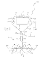
- FIG. 3 is a front view showing a schematic configuration of the weighing and packaging system 100.
- the weighing and packaging system 100 mainly includes a combination weighing unit 2, a bag making and packaging unit 3, a film supply unit 4, an operation switch 5, a liquid crystal display 6, and a control unit 7 (see FIG. 8).
- the combination weighing unit 2 measures a predetermined amount of the packaged item C by combination weighing.
- the package C is a light and brittle food such as potato chips.
- the combination weighing unit 2 discharges the measured packaging object C downward and supplies it to the bag making and packaging unit 3. The detailed configuration and operation of the combination weighing unit 2 will be described later.
- the bag making and packaging unit 3 is disposed below the combination weighing unit 2.
- the bag making and packaging unit 3 wraps the supplied packaging material C with the film F in accordance with the timing when the packaging material C is supplied from the combination weighing unit 2.
- the film F is a sheet-like thin packaging material.
- the bag making and packaging unit 3 manufactures the bag B in which the article to be packaged C is sealed. The detailed configuration and operation of the bag making and packaging unit 3 will be described later.
- the film supply unit 4 is installed adjacent to the bag making and packaging unit 3.
- the film supply unit 4 supplies the film F to the bag making and packaging unit 3.
- a film roll 4 a around which the film F is wound is set in the film supply unit 4.
- the film supply unit 4 unwinds the film F from the film roll 4 a and supplies it to the bag making and packaging unit 3.
- the operation switch 5 and the liquid crystal display 6 are attached to the front surface of the weighing packaging system 100 main body.
- the liquid crystal display 6 is a touch panel display disposed at a position where the operator of the operation switch 5 can visually recognize.
- the operation switch 5 and the liquid crystal display 6 function as an input device that receives instructions for the weighing and packaging system 100 and settings related to the weighing and packaging system 100.
- the liquid crystal display 6 functions as an output device that displays information related to the weighing packaging system 100.
- the control unit 7 is a computer including a CPU, a ROM, a RAM, and the like.
- the control unit 7 is connected to the combination weighing unit 2, the bag making and packaging unit 3, the film supply unit 4, the operation switch 5, and the liquid crystal display 6.
- the control unit 7 controls the combination weighing unit 2, the bag making and packaging unit 3, and the film supply unit 4 based on inputs from the operation switch 5 and the liquid crystal display 6, and outputs various information to the liquid crystal display 6.
- the detailed configuration and operation of the control unit 7 will be described later.
- the combination weighing unit 2 is a weighing machine for measuring a predetermined amount of the object to be packaged C.
- the article to be packaged C weighed by the combination weighing unit 2 is supplied to the bag making and packaging unit 3.
- the combination weighing unit 2 mainly includes a dispersion feeder 21, a plurality of troughs 22, a plurality of pool hoppers 23, a plurality of weighing hoppers 24, a collecting chute 25, and a plurality of weight sensors 26.
- the supplied object to be packaged C is dropped near the center of the dispersion feeder 21.
- a plurality of troughs 22 are provided on the periphery of the dispersion feeder 21.
- the dispersion feeder 21 and the trough 22 are given vibrations from a vibrating device (not shown). Thereby, as shown by the arrows in FIG. 3, the articles to be packaged C supplied to the dispersion feeder 21 fall through the troughs 22 and are stored in the pool hoppers 23 corresponding to the troughs 22.
- Each pool hopper 23 is disposed above the weighing hopper 24 corresponding to each pool hopper 23.
- the pool hopper 23 temporarily stores the articles C to be supplied to the corresponding weighing hoppers 24.
- Each weighing hopper 24 has a weight sensor 26.
- the weight sensor 26 outputs a load signal corresponding to the weight of the article to be packaged C supplied to the corresponding weighing hopper 24.
- the weight sensor 26 is, for example, a load cell.
- the combination weighing of the article C to be packaged by the combination weighing unit 2 is performed according to the following procedure.
- the weight sensor 26 detects the weight of the articles C to be stored in the weighing hoppers 24.
- the combination closest to the desired value is obtained by calculation.
- the desired value is the weight of a predetermined amount of the object to be packaged C supplied to the bag making and packaging unit 3.
- the articles to be packaged C are discharged from the weighing hopper 24 corresponding to the obtained combination toward the collecting chute 25.
- a predetermined amount of the articles C to be packaged discharged to the collecting chute 25 is supplied to the bag making and packaging unit 3.
- the weighing hopper 24 that has been emptied after being discharged is replenished with the weighing object C, whereby the combination weighing for measuring a predetermined amount of the weighing object C is executed again.
- the combination weighing unit 2 includes ten weighing hoppers 24.
- the ten weighing hoppers 24 are arranged at equal intervals along a virtual circumference (see FIG. 9).
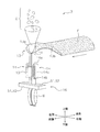
- FIG. 4 is a perspective view showing a schematic configuration of the bag making and packaging unit 3.
- six directions consisting of “front (front)”, “rear (back)”, “up”, “down”, “left” and “right” are defined as shown in FIG. .
- the bag making and packaging unit 3 mainly includes a forming mechanism 13, a pull-down belt mechanism 14, a vertical sealing mechanism 15, a horizontal sealing mechanism 16, and a rotary encoder 40.
- the forming mechanism 13 forms the sheet-like film F supplied from the film supply unit 4 into a cylindrical shape.
- the pull-down belt mechanism 14 conveys the film F formed into a cylindrical shape downward.
- the vertical sealing mechanism 15 seals the overlapping portion of both end portions of the film F formed into a cylindrical shape in the vertical direction parallel to the transport direction to form the cylindrical film Fc.
- the horizontal sealing mechanism 16 seals the cylindrical film Fc at two locations in the horizontal direction orthogonal to the transport direction, and forms a bag B in which the upper end and the lower end are horizontally sealed.
- the rotary encoder 40 detects the biting in the sealed portion of the tubular film Fc by the lateral sealing mechanism 16.
- the forming mechanism 13 includes a tube 13a and a former 13b.
- the tube 13a is a cylindrical member having an open upper end and a lower end.
- An article C to be packaged supplied from the combination weighing unit 2 is put into the opening at the upper end of the tube 13a.
- the former 13b is disposed so as to surround the tube 13a.
- the pull-down belt mechanism 14 conveys the film F wound around the tube 13a downward while adsorbing it.
- the pull-down belt mechanism 14 mainly includes a driving roller 14a, a driven roller 14b, and a pair of belts 14c. As shown in FIG. 4, the pair of belts 14c are arranged so as to sandwich the tube 13a on both the left and right sides of the tube 13a, and have a mechanism for adsorbing the film F formed into a cylindrical shape.
- the pull-down belt mechanism 14 conveys the film F formed into a cylindrical shape downward by rotating the pair of belts 14c by the driving roller 14a and the driven roller 14b.
- the vertical seal mechanism 15 seals the film F formed in a cylindrical shape in the vertical direction (vertical direction in FIG. 4).
- the vertical seal mechanism 15 is disposed on the front side of the tube 13a.
- the vertical seal mechanism 15 is moved in the front-rear direction so as to approach the tube 13a or away from the tube 13a by a drive mechanism (not shown).
- the vertical sealing mechanism 15 heats the overlapping portion of the film F in the vertical direction by heating the overlapping portion of the film F against the tube 13a with a constant pressure by the driving mechanism, thereby forming the tubular film Fc.
- the vertical sealing mechanism 15 includes a heater that heats the overlapping portion of the film F, a heater belt that contacts the overlapping portion of the film F, and the like.
- the lateral seal mechanism 16 includes a pair of seal jaws 51 (a seal jaw 51a and a seal jaw 51b) or a pair of seal jaws 52 (a seal jaw 52a and a seal jaw 52b). Accordingly, the sealed portion of the tubular film Fc conveyed downward is sandwiched along a direction (here, the left-right direction) intersecting the conveying direction of the tubular film Fc, and is laterally sealed.
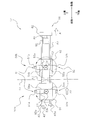
- FIG. 5 is a side view of the lateral seal mechanism 16 as viewed from the right.
- FIG. 6 is a side view of the trajectory of the pair of sealing jaws 51 and 52 of the lateral sealing mechanism 16 as viewed from the right direction.
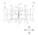
- FIG. 7 is a side view of a state in which the pair of sealing jaws 51 and 52 of the lateral sealing mechanism 16 is performing a sealing operation.
- the horizontal seal mechanism 16 mainly includes a first rotating body 50a, a second rotating body 50b, and a horizontal direction pressing mechanism 56 as shown in FIG.
- the first rotating body 50a is arranged on the front side of the tubular film Fc (left side in FIG. 5).
- the 2nd rotary body 50b is distribute
- the horizontal pressing mechanism 56 is a cylinder between the pair of sealing jaws 51 or the pair of sealing jaws 52 when the cylindrical film Fc is sandwiched between the pair of sealing jaws 51 or the pair of sealing jaws 52.
- the first rotating shaft 53a of the first rotating body 50a is constantly pressed toward the second rotating shaft 53b of the second rotating body 50b (rearward) so that the film-like film Fc is pressurized.
- the direction in which the first rotating shaft 53a is pressed toward the second rotating shaft 53b is drawn by a right-pointing arrow A1.
- the first rotating body 50a mainly includes a first rotating shaft 53a, a pair of levers 54a, a pair of levers 55a, a sealing jaw 51a, It has a seal jaw 52a.
- the first rotating shaft 53a is a rotating shaft of the first rotating body 50a extending in the left-right direction.
- the first rotating body 50a rotates around the rotation center C1 with the first rotation shaft 53a as a rotation axis in a side view (see FIG. 5).
- the pair of levers 54a is connected to the vicinity of both ends in the longitudinal direction of the first rotating shaft 53a (near both ends in the left-right direction). Each lever 54a extends from the first rotation shaft 53a in the radial direction of the first rotation shaft 53a. Each lever 54a extends in parallel from the first rotating shaft 53a in the same direction as the other lever 54a.
- the pair of levers 55a are connected to both ends in the longitudinal direction of the first rotating shaft 53a (near both ends in the left-right direction). Each lever 55a extends in the radial direction of the first rotation shaft 53a from the first rotation shaft 53a. Each lever 55a extends in parallel from the first rotation shaft 53a in the same direction as the other lever 55a.
- the lever 54a and the lever 55a connected to the vicinity of the right end of the first rotating shaft 53a extend symmetrically with respect to the rotation center C1 of the first rotating body 50a in a side view (see FIG. 5).
- the lever 54a and the lever 55a connected near the right end of the first rotating shaft 53a extend in the opposite direction with respect to the rotation center C1 of the first rotating body 50a in a side view (see FIG. 5).
- the lever 54a and the lever 55a connected to the vicinity of the left end of the first rotating shaft 53a extend in point symmetry with respect to the rotation center C1 of the first rotating body 50a in a side view.
- the lever 54a and the lever 55a connected to the vicinity of the left end of the first rotating shaft 53a extend in the opposite direction with respect to the rotation center C1 of the first rotating body 50a in a side view.
- the sealing jaw 51a constitutes one of the pair of sealing jaws 51.
- the seal jaw 51 is an example of a seal member.
- the seal jaw 51a has a seal surface 511a whose longitudinal direction is the left-right direction (see FIG. 7).
- the sealing jaw 51a functions as a pair with a sealing jaw 51b described later, and seals the sealed portion of the tubular film Fc. More specifically, the sealing jaw 51 includes a cylindrical film Fc including a sealing surface 511a whose longitudinal direction is the left-right direction of the sealing jaw 51a and a sealing surface 511b whose longitudinal direction is the lateral direction of a sealing jaw 51b described later. The part to be sealed is sandwiched and laterally sealed in the horizontal direction (see FIG. 7).
- the both ends of the sealing jaw 51a in the longitudinal direction (left-right direction) of the sealing surface 511a are respectively connected to the end of the lever 54a extending from the first rotating shaft 53a. Since the lever 54a is connected to the first rotation shaft 53a as described above, the seal jaw 51a is connected to the first rotation shaft at both ends in the longitudinal direction (left-right direction) of the seal surface 511a via the pair of levers 54a. 53a is supported.
- the seal jaw 52a constitutes one of the pair of seal jaws 52.
- the seal jaw 52 is an example of a seal member.
- the seal jaw 52a has a seal surface (not shown) whose longitudinal direction is the left-right direction.
- the sealing jaw 52a functions as a pair with a sealing jaw 52b described later, and seals the sealed portion of the tubular film Fc. More specifically, the sealing jaw 52 has a cylindrical shape with a sealing surface whose longitudinal direction is the left-right direction of the sealing jaw 52a and a sealing surface (not shown) whose longitudinal direction is the lateral direction of the sealing jaw 52b described later. The part to be sealed of the film Fc is sandwiched and horizontally sealed in the left-right direction.
- Both ends of the sealing jaw 52a in the longitudinal direction (left-right direction) of the sealing surface are respectively connected to the end of the lever 55a extending from the first rotating shaft 53a. Since the lever 55a is connected to the first rotating shaft 53a as described above, the sealing jaw 52a is connected to the first rotating shaft at both ends in the longitudinal direction (left-right direction) of the sealing surface via the pair of levers 55a. 53a is supported. Further, since the lever 54a and the lever 55a extend in opposite directions with respect to the rotation center C1 of the first rotating body 50a in a side view, the sealing jaw 52a rotates the sealing jaw 51a and the first rotating body 50a. It is arranged at a position 180 ° apart around the center C1.
- the second rotating body 50b mainly includes a second rotating shaft 53b, a pair of levers 54b, a pair of levers 55b, a sealing jaw 51b, It has a seal jaw 52b.
- the second rotating shaft 53b is a rotating shaft of the second rotating body 50b extending in the left-right direction.
- the second rotating body 50b rotates around the rotation center C2 with the second rotation shaft 53b as a rotation axis in a side view (see FIG. 5).
- the pair of levers 54b is connected to the vicinity of both ends in the longitudinal direction of the second rotating shaft 53b (near both ends in the left-right direction). Each lever 54b extends from the second rotation shaft 53b in the radial direction of the second rotation shaft 53b. Each lever 54b extends in parallel from the second rotating shaft 53b in the same direction as the other lever 54b.
- the pair of levers 55b are connected to both ends in the longitudinal direction of the second rotating shaft 53b (near both ends in the left-right direction). Each lever 55b extends from the second rotation shaft 53b in the radial direction of the second rotation shaft 53b. Each lever 55b extends in parallel from the second rotation shaft 53b in the same direction as the other lever 55b.
- the lever 54b and the lever 55b connected to the vicinity of the right end of the second rotating shaft 53b extend point-symmetrically with respect to the rotation center C2 of the second rotating body 50b in a side view (see FIG. 5).
- the lever 54b and the lever 55b connected near the right end of the second rotating shaft 53b extend in the opposite direction with respect to the rotation center C2 of the second rotating body 50b in a side view (see FIG. 5).
- the lever 54b and the lever 55b connected to the vicinity of the left end of the second rotating shaft 53b extend symmetrically with respect to the rotation center C2 of the second rotating body 50b in a side view.
- the lever 54b and the lever 55b connected near the left end of the second rotating shaft 53b extend in the opposite direction with respect to the rotation center C2 of the second rotating body 50b in a side view.
- the sealing jaw 51b constitutes one of the pair of sealing jaws 51.
- the seal jaw 51b has a seal surface 511b whose longitudinal direction is the left-right direction (see FIG. 7). As described above, the sealing jaw 51b functions as a pair with the sealing jaw 51a, and seals the sealed portion of the tubular film Fc.
- Both ends of the sealing jaw 51b in the longitudinal direction (left-right direction) of the sealing surface 511b are respectively connected to the end of the lever 54b extending from the second rotating shaft 53b. Since the lever 54b is connected to the second rotating shaft 53b as described above, the sealing jaw 51b is connected to the second rotating shaft at both ends in the longitudinal direction (left-right direction) of the sealing surface 511b via the pair of levers 54b. It is supported by 53b.
- the sealing jaw 52b constitutes one of the pair of sealing jaws 52.
- the seal jaw 52b has a seal surface (not shown) whose longitudinal direction is the left-right direction. As described above, the sealing jaw 52b functions as a pair with the sealing jaw 52a, and seals the sealed portion of the tubular film Fc.
- the both ends of the sealing jaw 52b in the longitudinal direction (left-right direction) of the sealing surface are respectively connected to the end of the lever 55b extending from the second rotating shaft 53b. Since the lever 55b is connected to the second rotating shaft 53b as described above, the sealing jaw 52b is connected to the second rotating shaft at both ends in the longitudinal direction (left-right direction) of the sealing surface via the pair of levers 55b. It is supported by 53b. Further, since the lever 54b and the lever 55b extend in opposite directions with respect to the rotation center C2 of the second rotating body 50b in the side view, the sealing jaw 52b rotates the sealing jaw 51b and the second rotating body 50b. It is arranged at a position 180 ° apart around the center C2.
- the first rotating body 50a is rotated in a side view when the first rotating shaft 53a is driven by a drive motor (not shown). It is rotated around the center C1 (see FIG. 6).
- the second rotating body 50b is rotated about the rotation center C2 in a side view when the second rotating shaft 53b is driven by a drive motor (not shown) (see FIG. 6).
- the seal jaw 51a and the seal jaw 52a are rotated along a circular orbit about the rotation center C1 and the seal jaw 51b and the seal jaw 52b are centered on the rotation center C2 (see FIG. 6).
- the first rotating body 50a is rotated clockwise around the rotation center C1 when viewed from the right side (see FIG. 6).
- the seal jaw 51a and the seal jaw 52a are rotated clockwise around the rotation center C1 when viewed from the right side.
- the second rotating body 50b is rotated counterclockwise around the rotation center C2 (see FIG. 6).
- the seal jaw 51b and the seal jaw 52b are rotated counterclockwise around the rotation center C2 when viewed from the right side.
- the first rotating body 50a is supported at its both ends by a horizontal moving plate 61 (see FIG. 5) in the horizontal sealing direction (in the left-right direction). More specifically, both ends of the first rotating shaft 53a of the first rotating body 50a in the left-right direction are supported by the horizontal moving plate 61.
- both ends of the second rotating body 50b are supported by the fixing plates 62 (see FIG. 5) in the horizontal sealing direction (in the left-right direction). More specifically, both ends of the second rotating shaft 53b of the second rotating body 50b in the left-right direction are supported by the fixed plate 62.
- the fixed plate 62 is fixed to a frame (not shown) of the bag making and packaging unit 3a.
- the horizontal moving plate 61 is pressed toward the fixed plate 62 by the horizontal direction pressing mechanism 56 (see arrow A1 in FIG. 5). As a result, the first rotating shaft 53 a supported by the horizontal moving plate 61 is pressed toward the second rotating shaft 53 b supported by the fixed plate 62 by the horizontal direction pressing mechanism 56.
- the horizontal direction pressing mechanism 56 will be described.
- the horizontal direction pressing mechanism 56 is an example of a fluid pressure utilization pressing mechanism.
- the horizontal direction pressing mechanism 56 presses the first rotating shaft 53a toward the second rotating shaft 53b using air pressure.
- the horizontal direction pressing mechanism 56 uses air pressure, but is not limited thereto, and may use, for example, oil pressure.
- the horizontal direction pressing mechanism 56 mainly has an air cylinder 80, a first connecting rod 81, a connecting plate 82, and a second connecting rod 83 as shown in FIG.
- the air cylinder 80 is driven by air pressure.
- the air cylinder 80 is connected to the connection plate 82 via a first connection rod 81 extending rearward from the air cylinder 80.
- force is transmitted through the first connecting rod 81 and the connecting plate 82 is pressed rearward.
- a direction in which the connecting plate 82 is pressed is indicated by a right-pointing arrow A ⁇ b> 1.
- the second connecting rod 83 is a rod-shaped member that connects the connecting plate 82 and the horizontal moving plate 61.
- the horizontal direction pressing mechanism 56 has four second connecting rods 83. One end of the second connecting rod 83 is connected to the connecting plate 82.
- the two second connecting rods 83 extend in parallel from the vicinity of the upper right corner and the lower right corner of the connecting plate 82 toward the front. Although not shown, the remaining two second connecting rods 83 extend in parallel from the vicinity of the upper left corner and the lower left corner of the connecting plate 82 toward the front.
- Two second connecting rods 83 extending forward from the vicinity of the right end of the connecting plate 82 are connected to the horizontal moving plate 61 disposed on the right side of the first rotating body 50a.
- the two second connecting rods 83 extending forward from the vicinity of the left end portion of the connecting plate 82 are connected to the horizontal moving plate 61 disposed on the left side of the first rotating body 50a.
- the second connecting rod 83 is not connected to the fixed plate 62 and extends through the fixed plate 62 so as to be slidable.
- the vicinity of the end (front end) of the second connecting rod 83 opposite to the connecting plate 82 is slidably supported by a rod support member 83a fixed to the frame of the bag making and packaging unit 3a. Since the second connecting rod 83 is slidably supported by the rod support member 83a, the horizontal moving plate 61 connected to the second connecting rod 83 can move in a direction approaching or moving away from the fixed plate 62. .
- the first rotating shaft 53a supported by the horizontal moving plate 61 is movable in a direction approaching or separating from the second rotating shaft 53b supported by the fixed plate 62.
- the force by the air cylinder 80 and the force acting on the sealing jaw 51a from the sealing jaw 51b or the sealing jaw 52a from the sealing jaw 52b when the cylindrical film Fc is laterally sealed by the sealing jaw 51 or the sealing jaw 52 The first rotating shaft 53a moves in a direction approaching or leaving the second rotating shaft 53b.
- the first rotating body 50a and the second rotating body 50b rotate (refer to the arrows shown in the two-dot chain line portion in FIG. 6 for the rotation direction), and the first rotating shaft 53a is moved to the second rotating shaft 53b by the horizontal direction pressing mechanism 56. (Refer to the arrow A2 shown below the first rotating body 50a in FIG. 6 for the pressing direction), the sealing jaw 51a and the sealing jaw 51b are connected to the sealing surface 511a and the sealing jaw of the sealing jaw 51a. Between the sealing surfaces 511b of 51b, the cylindrical film Fc conveyed downward is pinched and pressurized (see FIG. 7).
- the seal surface 511a and the seal surface 511b have serrations 512a and serrations 512b that mesh with each other, as shown in FIG.
- the seal jaw 51 sandwiches the tubular film Fc so that the teeth of the serration 512a of the seal surface 511a and the teeth of the serration 512b of the seal surface 511b are engaged, and pressurizes the tubular film Fc.
- a heater 71 (see FIG. 7) is provided inside the seal jaw 51a and the seal jaw 51b, and the heater 71 heats the seal surface 511a and the seal surface 511b.
- the sealed portion of the cylindrical film Fc is heat-sealed.
- the cylindrical film Fc conveyed downward is heat-sealed in order from the downstream side (front side in the conveyance direction) to the upstream side (rear side in the conveyance direction).
- a knife 72a for separating the bag B from the tubular film Fc is attached to the seal jaw 51b near the center in the short direction of the seal surface 511b (the direction orthogonal to the longitudinal direction of the seal surface 511b).
- the knife 72a is attached so that the cutting edge protrudes toward the sealing jaw 51a during the sealing operation by the sealing jaw 51a and the sealing jaw 51b (see FIG. 7).
- a groove 72b is formed near the center of the seal surface 511a in the short direction (a direction perpendicular to the longitudinal direction of the seal surface 511a).
- the groove 72b engages with the knife 72a protruding from the seal jaw 51b toward the seal jaw 51a.
- the knife 72a is formed as a slant blade, and cuts the bag B from the tubular film Fc from one end side to the other end side in the horizontal sealing direction (left-right direction).
- Step 1 The cylindrical film Fc is laterally sealed.
- Step 2 On the upstream side of the position where the horizontal sealing is performed in Step 1, the bag B which is horizontally sealed using the knife 72a is cut from the tubular film Fc.
- Step 3 The cylindrical film Fc is laterally sealed upstream from the position cut by the knife 72a in Step 2.
- the timing at which the horizontal seal or the tubular film Fc is cut in steps 1 to 3 may partially overlap with the timing at which other steps 1 to 3 are performed.
- the cutting of the tubular film Fc in Step 2 may be started at the timing when the horizontal seal in Step 1 is not completely finished, and the cutting of the tubular film Fc in Step 2 is not finished.
- the lateral seal of step 3 may be started.
- the rotary encoder 40 is fixed to the frame of the bag making and packaging unit 3a.
- the rotary shaft of the rotary encoder 40 has an end on the front side of the second connecting rod 83 (the side opposite to the side connected to the connecting plate 82) so that the second connecting rod 83 rotates in the front-rear direction. Is engaged with the part.
- Two rotary encoders 40 are provided.
- a rotary shaft of one rotary encoder 40 is engaged with an end portion of the second connecting rod 83 arranged on the upper right side among the four second connecting rods 83.
- the rotating shaft of the other rotary encoder 40 is engaged with the end of the second connecting rod 83 arranged on the upper left side.
- the rotating shaft of one rotary encoder 40 engages with the edge part of the 2nd connecting rod 83 distribute
- the rotating shaft may be engaged with the end of the second connecting rod 83 arranged on the lower left side.
- the rotary encoder 40 measures the amount of movement of the second connecting rod 83 in the front-rear direction by measuring the rotation angle of the rotary shaft of the rotary encoder 40.
- the amount of movement of the second connecting rod 83 in the front-rear direction is such that the second rotating shaft attached to the fixed plate 62 of the first rotating shaft 53a attached to the horizontal moving plate 61 connected to the second connecting rod 83. It is equal to the movement amount for 53b.
- the rotary encoder 40 measures the rotation angle of the rotary shaft of the rotary encoder 40, whereby the first rotary shaft 53a in the direction in which the first rotary shaft 53a approaches or separates from the second rotary shaft 53b. The amount of movement with respect to the two rotation shafts 53b is measured.
- the rotary encoder 40 moves the second connecting rod 83 connected to the horizontal moving plate 61 disposed on the right side of the first rotating shaft 53a and the first rotating shaft 53a.
- the amount of movement of the second connecting rod 83 connected to the horizontal moving plate 61 arranged on the left side is measured.
- the rotary encoder 40 moves the first rotation shaft 53a on the right end side with respect to the second rotation shaft 53b (right side movement amount) and the second rotation shaft 53b of the first rotation shaft 53a on the left end side.
- the amount of movement (the amount of left-side movement) is measured. Therefore, even when only one of the left and right end portions of the first rotation shaft 53a approaches or separates from the second rotation shaft 53b, this can be detected.
- the rotary encoder 40 is used to detect the occurrence of biting in the sealed portion of the tubular film Fc when the tubular film Fc is laterally sealed by the sealing jaws 51 and 52.
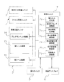
- FIG. 8 is a block diagram of the control unit 7.
- the control unit 7 is connected to the combination weighing unit 2, the film supply unit 4, the pull-down belt mechanism 14, the vertical sealing mechanism 15, the horizontal sealing mechanism 16, the operation switch 5, and the liquid crystal display 6.
- the control unit 7 includes a biting determination unit 7a, a discharge timing adjustment unit 7b, a discharge interval adjustment unit 7c, a discharge container number adjustment unit 7d, a discharge container position adjustment unit 7e, a discharge container order adjustment unit 7f, And a packaging capacity adjusting unit 7g.
- the discharge timing adjustment unit 7b, the discharge interval adjustment unit 7c, the discharge container number adjustment unit 7d, the discharge container position adjustment unit 7e, the discharge container order adjustment unit 7f, and the packaging capacity adjustment unit 7g are collectively adjusted as necessary. These are called parts 7b to 7g.
- the biting determination unit 7a and the adjustment units 7b to 7g are programs stored in the control unit 7. Details of these programs will be described later.
- the control unit 7 is connected to each component of the combination weighing unit 2 and constitutes a part of the combination weighing unit 2 as a control unit of the combination weighing unit 2.
- the control unit 7 also includes each component of the bag making and packaging unit 3 (mainly, a pull-down belt mechanism 14, a vertical seal mechanism 15, a horizontal seal mechanism 16 (drive motors for driving the first and second rotary shafts 53a and 53b, And the air cylinder 80 of the horizontal direction pressing mechanism 56), the rotary encoder 40, and the film supply unit 4).
- the control unit 7 constitutes a part of the bag making and packaging unit 3 as a control unit of the bag making and packaging unit 3.
- the control unit 7 controls the combination weighing unit 2 and the bag making and packaging unit 3 by executing the stored program. For example, the control unit 7 controls the combination weighing unit 2 and the bag making and packaging unit 3 so that the combination weighing unit 2 and the bag making and packaging unit 3 perform the following operations.
- the weight of the article to be packaged C is weighed by a plurality of weighing hoppers 24, and these weighed values are combined so as to have a predetermined total amount. It is discharged downward.
- the control unit 7 controls the combination weighing unit 2 so that these series of operations are performed.
- the article C to be packaged discharged from the combination weighing unit 2 is dropped onto the upper opening end of the tube 13a of the bag making and packaging unit 3.
- the control unit 7 controls the film supply unit 4 as a control unit for controlling the bag making and packaging unit 3 so that the film F is supplied to the forming mechanism 13. Further, the control unit 7 is a control unit for controlling the bag making and packaging unit 3 so that the film F (tubular film Fc) formed in a cylindrical shape by the forming mechanism 13 is transported downward. To control. Further, the control unit 7 controls the vertical sealing mechanism 15 as a control unit for controlling the bag making and packaging unit 3 so that the overlapping portion of both ends of the tubular film Fc conveyed downward is sealed in the vertical direction. To do.
- control unit 7 is a control unit for controlling the bag making and packaging unit 3 and is directed downward in accordance with the timing at which the articles C to be packaged discharged from the combination weighing unit 2 are discharged from the lower opening end of the tube 13a.
- the horizontal sealing mechanism 16 is controlled so that the cylindrical film Fc conveyed in this manner is sealed in the horizontal direction and the sealed bag B is separated from the upstream cylindrical film Fc.
- the control unit 7 has a biting determination unit 7 a as one of the functions of the bag making and packaging unit 3.
- the biting determination unit 7a is based on the amount of movement of the first rotating shaft 53a with respect to the second rotating shaft 53b (the amount of right-side movement and the amount of left-side movement) measured by the rotary encoder 40 during lateral sealing by the seal jaws 51 and 52. Then, it is determined whether or not biting has occurred in the sealed portion of the tubular film Fc.
- the biting in the sealed portion of the tubular film Fc occurs, for example, when the package C and the cutting residue of the tubular film Fc are sandwiched between the sealing jaws 51 and 52 in the sealed portion.
- the main cause of the occurrence of biting in the sealed portion of the tubular film Fc is the timing at which the falling behavior of the packaging object C in the tube 13a is disturbed and the packaging object C is put into the cylindrical film Fc. Is deviated from normal.
- the specific causes of the disorder of the fall behavior of the packaged article C are that the size and weight of the packaged article C vary, the packaged article C is temporarily clogged in the tube 13a, and the packaged article C Is swollen by an air current or the like in the tube 13a, and the packaging object C dropped from the plurality of weighing hoppers 24 collides in the tube 13a.
- the biting determination unit 7a of the control unit 7 moves the first rotary shaft 53a relative to the second rotary shaft 53b between when the sealed portion is not bitten and when the sealed portion is bitten. The presence / absence of biting is determined using the difference.
- the biting determination unit 7a can acquire the height position where biting has occurred based on a change in the amount of movement over time when the portion to be sealed is bitten. For example, in the sealing jaws 51a and 51b shown in FIG. 7, the biting determination unit 7a can acquire at which height position (vertical position) of the sealing surfaces 511a and 511b the biting has occurred. . Thereby, for example, the biting determination unit 7a determines whether biting has occurred above the knife 72a and the groove 72b or whether biting has occurred below the knife 72a and the groove 72b. it can.
- control unit 7 of the weighing packaging system 100 determines whether or not the packaged item C or the like is bitten in the sealed portion of the tubular film Fc based on the measurement data of the movement amount by the rotary encoder 40. To do. Each time the lateral sealing mechanism 16 laterally seals the tubular film Fc, the biting determination unit 7a determines whether or not biting has occurred in the laterally sealed portion.
- the control unit 7 controls the operations of the combination weighing unit 2 and the bag making and packaging unit 3 so that no further biting occurs when the biting rate exceeds the target upper limit value.
- the biting rate is calculated, for example, based on the number of times biting is detected by the biting determination unit 7a every time the bag making and packaging unit 3 performs the horizontal sealing operation a predetermined number of times.
- the predetermined number of times is, for example, 1000, but can be arbitrarily set.
- the biting occurrence rate is calculated as 10 out of 1000 times, that is, 1%.
- control unit 7 When the biting occurrence rate exceeds a predetermined target upper limit value (for example, 2%), the control unit 7 operates the combination weighing unit 2 and the bag making and packaging unit 3 to suppress the biting occurrence rate below the target upper limit value. To control. This control is executed by the adjusting units 7b to 7g of the control unit 7.
- a predetermined target upper limit value for example, 2%
- the control unit 7 controls the operations of the combination weighing unit 2 and the bag making and packaging unit 3 based on the biting information when the biting rate exceeds the target upper limit value.
- the biting information is information regarding the biting state in the sealed portion of the tubular film Fc.
- the biting information is, for example, information on the height position where biting has occurred on the seal surfaces of the seal jaws 51 and 52.
- the biting determination unit 7a can acquire biting information when detecting biting in the sealed portion of the tubular film Fc.
- the control unit 7 executes at least one of the adjusting units 7b to 7g.
- the program executed by the control unit 7 can be arbitrarily set.
- the control unit 7 may execute only one program of the adjusting units 7b to 7g, or may execute a combination of a plurality of programs of the adjusting units 7b to 7g.
- the discharge timing adjustment unit 7b discharges the packaging material C from the weighing hopper 24 so that the packaging material C discharged from the weighing hopper 24 is not sandwiched between the sealing jaws 51 and 52. Automatically adjust the timing.
- the discharge timing adjustment unit 7b discharges the packaged article C from the weighing hopper 24.
- the timing to be delayed is delayed by a predetermined time.
- the discharge timing adjustment unit 7b discharges the package C from the weighing hopper 24.
- the timing to be set is advanced by a predetermined time.
- the discharge timing adjusting section 7b can reduce the occurrence of biting in the sealed portion of the tubular film Fc by automatically adjusting the timing at which the package C is discharged.
- (5-2) Discharge Interval Adjustment Unit When the control unit 7 discharges the package C from the plurality of weighing hoppers 24 selected by the combination weighing unit 2, the control unit 7 simultaneously removes the package C from the plurality of weighing hoppers 24. The operation of discharging the package C from one weighing hopper 24 without discharging is performed a plurality of times while leaving a predetermined time interval (hereinafter referred to as “discharge interval”). The packaged item C can be discharged.
- the discharge interval adjusting unit 7c automatically adjusts the discharge interval.
- the discharge interval is set, for example, at an interval of 20 milliseconds.
- the upper limit value of the discharge interval is set to 200 milliseconds, for example, and can be set to other values.
- the longer the discharge interval the longer the discharge interval, which is the time from the time when the article to be packaged C is discharged from one weighing hopper 24 to the time when the object to be packaged C is discharged from the next weighing hopper 24. As the discharge interval is longer, the articles C to be packaged discharged from the plurality of weighing hoppers 24 are more dispersed and fall in the tube 13a.
- the discharge interval adjusting unit 7c disperses and drops the articles to be packaged C in the tube 13a, so that the articles to be packaged C discharged from the plurality of weighing hoppers 24 are dropped while being dropped in the tube 13a. Suppresses collision.
- the objects to be packaged C that collide may become a large lump, and the article to be packaged C may be temporarily clogged in the tube 13a.
- the frequency of collision of the article to be packaged C in the tube 13a decreases, and temporary clogging of the article to be packaged C in the tube 13a is also suppressed. .
- the timing at which the articles to be packaged C are put into the cylindrical film Fc is delayed, and the articles to be packaged C may be sandwiched between the seal jaws 51 and 52. is there. Therefore, as the article to be packaged C is more dispersed and falls in the tube 13a, the article to be packaged C is suppressed from being sandwiched between the seal jaws 51 and 52.
- the discharge interval adjusting unit 7c can reduce the occurrence of biting in the sealed portion of the tubular film Fc by automatically adjusting the discharge interval.
- the number of discharge containers adjusting section 7d is the number of discharge containers that are the number of weighing hoppers 24 that discharge the objects to be packaged C when the combination weighing unit 2 measures the objects to be packaged C in combination. Automatically adjust the number.
- the number of discharge containers may be different each time the combination weighing unit 2 combines and measures the articles to be packaged C. Therefore, as the number of discharge containers, it is assumed that an average value of the number of weighing hoppers 24 that discharge the packaged article C when the combination weighing unit 2 combines and measures the packaged article C a predetermined number of times is used.
- the number of discharge containers can be set in units of 0.5, for example.
- the discharge container number adjusting unit 7d increases the number of discharge containers so that the articles to be packaged C are dispersed and dropped in the tube 13a, and the articles to be packaged C discharged from the plurality of weighing hoppers 24 are contained in the tubes 13a. So as not to be temporarily clogged in the tube 13a by colliding with each other while being dropped. Therefore, as the article to be packaged C is more dispersed and dropped in the tube 13a, temporary clogging of the article to be packaged C in the tube 13a is suppressed, and the article to be packaged C is sandwiched between the seal jaws 51 and 52. Is suppressed.
- the discharge container number adjusting unit 7d can automatically adjust the number of discharge containers to reduce the occurrence of biting in the sealed portion of the tubular film Fc.
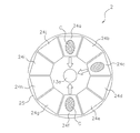
- FIG. 9 is a diagram schematically showing the arrangement of the ten weighing hoppers 24a to 24j when the combination weighing unit 2 is viewed from above along the vertical direction.
- the weighing hoppers 24b to 24j are arranged clockwise from the position where the weighing hopper 24a is arranged.
- the positions of the collecting chute 25 and the tube 13a of the bag making and packaging unit 3 are indicated by dotted lines for reference.
- the weighing hopper 24a and the weighing hopper 24f are arranged at positions facing each other across the tube 13a. Therefore, when the articles to be packaged C are simultaneously discharged from the weighing hopper 24a and the weighing hopper 24f, the articles to be packaged C discharged from the weighing hopper 24a and the articles to be packaged C discharged from the weighing hopper 24f are shown in FIG. As indicated by the arrows, the slides down on the collecting chute 25 in opposite directions may cause a frontal collision when entering the tube 13a. If the articles to be packaged C discharged from the different weighing hoppers 24a to 24j collide front in the tube 13a, the articles to be packaged C may be temporarily clogged in the tube 13a as described above.
- the weighing hopper 24a and the weighing hopper 24c are not disposed at positions facing each other across the tube 13a.
- the articles to be packaged C are simultaneously discharged from the weighing hopper 24a and the weighing hopper 24c
- the articles to be packaged C discharged from the weighing hopper 24a and the objects to be packaged C discharged from the weighing hopper 24c are As indicated by the arrow 9, since they do not face each other when entering the tube 13 a, it is possible to prevent the article C from being temporarily clogged in the tube 13 a.
- the discharge container position adjusting unit 7e faces each other across the tube 13a when selecting a combination of the weighing hopper 24 based on the weight of the article C to be packaged temporarily stored in the weighing hopper 24.
- the discharge container position is automatically adjusted so that the set of related weighing hoppers 24 is not included in the combination. Thereby, temporary clogging of the article to be packaged C in the tube 13a is suppressed, and the article to be packaged C is suppressed from being sandwiched between the sealing jaws 51 and 52.
- the discharge container position adjusting unit 7e can reduce the occurrence of biting in the sealed portion of the tubular film Fc by automatically adjusting the discharge container position.
- the discharge container order adjustment section 7f temporarily stores in each weighing hopper 24 that discharges the article to be packaged C when the combination weighing unit 2 performs combination weighing on the article to be packaged C. Based on the weight of the packaged goods C, the order in which the packages C are discharged from the weighing hoppers 24 is automatically adjusted.
- the discharge container order adjusting unit 7f discharges the packages C in descending order of the weight of the packages C temporarily stored in the weighing hopper 24 that discharges the packages C, for example.
- the combination weighing unit 2 selects a combination of four weighing hoppers 24 when combining and weighing the articles C to be packaged.
- the weights of the articles C to be temporarily stored in the four weighing hoppers 24 are set as W1, W2, W3, and W4, respectively.
- the magnitude relationship between the weights W1 to W4 is W1 ⁇ W2 ⁇ W3 ⁇ W4.
- the discharge container sequence adjustment unit 7f includes four packages in the order of a packaged object C having a weight W4, a packaged object C having a weight W3, a packaged object C having a weight W2, and a packaged object C having a weight W1.
- the packaged article C is discharged from the weighing hopper 24 four times.
- the packaged article C is a light article such as potato chips
- the weight of the packaged article C that is discharged from the weighing hopper 24 and falls inside the tube 13a is small, an airflow from below is applied during the fall in the tube 13a.
- the packaged item C may rise and become difficult to fall.
- the packaged article C that has risen in the tube 13a collides with the packaged article C that has been discharged from another weighing hopper 24 and dropped in the tube 13a, the packaged article C in the tube 13a is temporarily clogged. May occur. On the contrary, such a collision is suppressed, so that the weight of the to-be-packaged product C which is discharged
- the discharge container sequence adjusting unit 7f discharges the packages C in descending order of the weight of the packages C temporarily stored in the weighing hopper 24 that discharges the packages C.
- temporary clogging of the article to be packaged C is suppressed, and the article to be packaged C is prevented from being sandwiched between the sealing jaws 51 and 52.
- the discharge container order adjusting unit 7f can automatically reduce the occurrence of biting in the sealed portion of the tubular film Fc by automatically adjusting the order in which the articles C are discharged from each weighing hopper 24. it can.
- the packaging capability adjusting unit 7g automatically adjusts the packaging capability, which is the capability of the bag making and packaging unit 3 to wrap the article C to be packed in the bag B per unit time.
- the packaging capacity is expressed as 20 bpm.
- the packaging capacity can be set in units of 5 bmp, for example.
- the packaging capacity adjusting unit 7g temporarily reduces the packaging capacity, and the timing at which the packaged article C is discharged from the weighing hopper 24. It is possible to easily synchronize the timing with which the horizontal sealing mechanism 16 performs horizontal sealing on the tubular film Fc. Thereby, it is suppressed that the to-be-packaged goods C are pinched
- the packaging capacity adjusting unit 7g can reduce the occurrence of biting in the sealed portion of the tubular film Fc by automatically adjusting the packaging capacity.
- the control unit 7 of the weighing and packaging system 100 controls the operations of the combination weighing unit 2 and the bag making and packaging unit 3 by the adjusting units 7b to 7g.
- the biting rate can be suppressed to a target upper limit value or less. That is, the control unit 7 is configured so that the combination weighing unit 2 and the bag making and packaging unit 3 can be used when the articles to be packaged C are frequently caught by the sealing jaws 51 and 52 of the lateral seal mechanism 16 during the operation of the weighing and packaging system 100.
- the weighing and packaging system 100 can quickly optimize the operations of the combination weighing unit 2 and the bag making and packaging unit 3 even if an abnormality is detected when packaging the article C to be packaged. Can do. Therefore, the weighing packaging system 100 can effectively suppress the generation of defective products and improve the operating rate.
- the control unit 7 of the weighing and packaging system 100 executes an arbitrary program of the adjusting units 7b to 7g.
- the control unit 7 may execute a plurality of programs of the adjustment units 7b to 7g in order based on a predetermined priority order.
- the control unit 7 is another program of the adjusting units 7b to 7g when the biting occurrence rate still exceeds the target upper limit value after executing one program of the adjusting units 7b to 7g.
- a program having a lower priority than the previously executed program is executed.
- the execution order of the programs is the same as the predetermined priority order.
- the control unit 7 sets the discharge interval adjusting unit 7c, the discharge container number adjusting unit 7d, the discharge container position adjusting unit 7e, and the packaging capacity adjusting unit 7g in this order. You may execute it one by one. In this case, the control unit 7 first determines whether or not the biting rate is equal to or lower than the target upper limit value after executing the discharge interval adjusting unit 7c, and the biting rate still exceeds the target upper limit value. If so, the discharge container number adjusting unit 7d is executed.
- the lowest priority is assigned to the packaging capacity adjustment unit 7g that may greatly affect the overall efficiency of the weighing packaging system 100. That is, when the control unit 7 executes a plurality of programs of the adjustment units 7b to 7g, it is preferable to execute the packaging capacity adjustment unit 7g last.
- the packages C are discharged in descending order of the weight of the packages C temporarily stored in the weighing hopper 24 that discharges the packages C.
- the control to do was explained.
- the discharge container sequence adjustment unit 7f is configured to store the packages C temporarily stored in the weighing hoppers 24 that discharge the packages C. Based on the weight, the packages C may be discharged based on other orders. In this case, the order of discharging the articles to be packaged C may be set by the user of the weighing and packaging system 100 using the operation switch 5 and the liquid crystal display 6.
- the combination weighing unit 2 selects a combination of four weighing hoppers 24 when the combination weighing unit 2 weighs the package C.
- the weights of the articles C to be temporarily stored in the four weighing hoppers 24 are set as W1, W2, W3, and W4, respectively.
- the magnitude relationship between the weights W1 to W4 is W1 ⁇ W2 ⁇ W3 ⁇ W4.
- the following first to fourth modes can be given as the settings relating to the order of discharging the articles to be packaged C.
- the packages C are discharged in descending order of the weight of the packages C.
- the discharge container sequence adjustment unit 7f includes four packages in the order of a packaged object C having a weight W4, a packaged object C having a weight W3, a packaged object C having a weight W2, and a packaged object C having a weight W1.
- the packaged article C is discharged from the weighing hopper 24 four times.
- the discharge order of such a packaged article C is expressed as W4 ⁇ W3 ⁇ W2 ⁇ W1.
- the packages C are discharged in ascending order of the weight of the packages C. That is, the discharge order of the packaged goods C is W1 ⁇ W2 ⁇ W3 ⁇ W4.
- the heaviest package C is discharged first, the lightest package C is discharged next, and this is repeated. That is, the discharge order of the packaged article C is W4 ⁇ W1 ⁇ W3 ⁇ W2.
- the lightest package C is discharged first, the heaviest package C is discharged next, and this is repeated. That is, the discharge order of the packaged article C is W1 ⁇ W4 ⁇ W2 ⁇ W3.
- the combination weighing unit 2 discharges the package C according to the weight of the package C supplied to the bag making and packaging unit 3 at a time, the shape and specific gravity of the package C, and the like.
- the order of discharging the articles C to be packaged temporarily stored in the weighing hopper 24 can be selected from the first to fourth modes.
- the user of the weighing and packaging system 100 selects the setting (first to fourth modes, etc.) relating to the order of discharging the articles to be packaged C from the plurality of weighing hoppers 24, so that the articles to be packaged C in the tube 13a. Can be prevented from temporarily clogging, and the occurrence of biting in the sealed portion of the tubular film Fc can be reduced.
Landscapes
- Engineering & Computer Science (AREA)
- Mechanical Engineering (AREA)
- Physics & Mathematics (AREA)
- General Physics & Mathematics (AREA)
- Containers And Plastic Fillers For Packaging (AREA)
Abstract
本発明の目的は、物品を包装する際に異常を検知しても、組み合わせ計量装置および包装装置の動作を自動的に調整して、動作の最適化を図ることができる計量包装システムを提供することである。計量包装システム(100)は、組合せ計量ユニット(2)と、製袋包装ユニット(3)と、制御ユニット(7)とを備える。組合せ計量ユニット(2)は、被包装物(C)を組み合わせ計量する。製袋包装ユニット(3)は、フィルム(F)から袋(B)を成形しつつ、組み合わせ計量された被包装物(C)を袋(B)で受けて包装する。製袋包装ユニット(3)は、フィルム(F)を横シールする一対のシールジョー(51,52)と、シールジョー(51,52)による被包装物(C)の噛み込みを検知するロータリエンコーダ(40)とを有する。制御ユニット(7)は、ロータリエンコーダ(40)が被包装物(C)の噛み込みを検知した場合に、被包装物(C)の噛み込みに関する情報に基づいて組合せ計量ユニット(2)の動作を調整する。
Description
本発明は、物品を組み合わせ計量し、計量された物品を包装する計量包装システムに関する。
従来、組み合わせ計量装置と包装装置とを備える計量包装システムが用いられている。組み合わせ計量装置は、複数の計量容器に物品を小分けし、小分けされた物品の合計重量が所定範囲内となるように計量容器の組み合わせを選択して、計量容器から物品を排出する。包装装置は、チューブ状に成形された包材の下端部を横シールした後、計量容器から排出された物品を包材の内側に投入して、包材の上端部を横シールすることにより、物品が封入された袋を製造する。
特許文献1(特開2010-137953号公報)には、組み合わせ計量装置の集合ホッパが開示されている。この集合ホッパは、被計量物である物品を貯留部で貯留し、貯留された物品を、一対のゲートを開いたときに形成される下部開口から落下排出させることにより、下部開口の下方に配置された包装装置の受入れ口へ物品を供給する。貯留部は、下方に向かうにつれて先細りの形状となっている。貯留部を形成する各ゲートの内面は、曲面状となっている。そのため、物品が微粉の発生しやすいスナック菓子等であっても、ゲートを開いたときに物品の微粉が遅れて落下することによる、包装装置でのシール不良および物品詰まりを防止できる。
しかし、従来の計量包装システムは、横シール機構が物品を噛み込むこと等によるシール不良、および、組み合わせ計量装置から排出された物品の詰まり等の異常を検知した場合に、システム全体をただちに停止させたり、包装装置の下流側に設置される検査装置を用いて、物品が噛み込まれた状態で横シールされた袋を検知して除去したりする。そのため、システムの停止、および、異常が検知された袋の除去によって、組み合わせ計量装置および包装装置の動作効率が低下するという問題点があった。
本発明の目的は、物品を包装する際に異常を検知しても、組み合わせ計量装置および包装装置の動作を自動的に調整して、動作の最適化を図ることができる計量包装システムを提供することである。
本発明に係る計量包装システムは、計量装置と、包装装置と、制御部とを備える。計量装置は、複数の計量容器に物品を小分けし、小分けされた物品の合計重量が所定範囲内となるように計量容器の組み合わせを選択し、選択された組み合わせに含まれる計量容器から物品を排出する。包装装置は、包材から袋を成形しつつ、計量装置から排出された物品を袋で受けて包装する。制御部は、計量装置および包装装置を制御する。包装装置は、一対のシール部と、検知部とを有する。一対のシール部は、包材を横方向に挟み込んでシールするためのものである。検知部は、一対のシール部による物品の噛み込みを検知する。制御部は、検知部が物品の噛み込みを検知した場合に、物品の噛み込みに関する噛み込み情報を取得し、噛み込み情報に基づいて計量装置の動作を調整する。
この計量包装システムは、包装装置の一対のシール部が、包材を横方向にシールする際に物品も噛み込んでしまう噛み込み異常を検知する。計量包装システムの制御部は、噛み込み異常を検知すると、噛み込み情報に基づいて、噛み込み異常がこれ以上起こらないように、計量装置の動作を制御する。噛み込み情報は、例えば、一対のシール部において物品が噛み込まれた位置である。制御部は、計量装置による物品の排出タイミング等を制御する。従って、計量包装システムは、物品を包装する際に異常を検知しても、計量装置および包装装置の動作を自動的に調整して、動作の最適化を図ることができる。
また、制御部は、計量容器から物品が排出されるタイミングを調整することが好ましい。
この計量包装システムは、計量容器から排出された物品が一対のシール部に噛み込まれないように、物品が排出されるタイミングを調整する。
また、計量装置は、組み合わせに含まれる計量容器から所定の時間間隔を空けて物品を排出し、制御部は、時間間隔を調整することが好ましい。
この計量包装システムは、複数の計量容器から排出された物品が、落下中に互いに衝突して詰まらないように、例えば、複数の計量容器から物品を1つずつ排出する際の時間間隔を長くすることで、計量装置から物品を分散させて排出する。これにより、計量装置から排出される物品の落下挙動が安定する。
また、制御部は、計量装置によって選択される組み合わせに含まれる計量容器の数を調整することが好ましい。
この計量包装システムは、複数の計量容器から排出された物品が、落下中に互いに衝突して詰まらないように、例えば、物品を排出する計量容器の数を増やすことで、計量装置から物品を分散させて排出する。これにより、計量装置から排出される物品の落下挙動が安定する。
また、制御部は、計量装置によって選択される組み合わせに含まれる計量容器の位置を調整することが好ましい。
この計量包装システムは、複数の計量容器から排出された物品が、落下中に互いに衝突して詰まらないように、物品を排出する計量容器の位置を調整する。これにより、計量装置から排出される物品の落下挙動が安定する。
また、制御部は、計量装置によって選択される組み合わせに含まれる計量容器内の物品の重量に基づいて、計量容器から物品を排出する順番を調整することが好ましい。
この計量包装システムは、複数の計量容器から排出された物品が、落下中に互いに衝突して詰まらないように、複数の計量容器から物品を1つずつ排出する際の順番を調整する。これにより、計量装置から排出される物品の落下挙動が安定する。
また、制御部は、検知部が物品の噛み込みを検知した場合に、包装装置が物品を包装する速度を調整することが好ましい。
この計量包装システムは、計量容器から排出された物品が一対のシール部に噛み込まれないように、例えば、包装装置の包装能力を一時的に低下させる。
本発明に係る計量包装システムは、物品を包装する際に異常を検知しても、組み合わせ計量装置および包装装置の動作を自動的に調整して、動作の最適化を図ることができる。
本発明の実施形態について、図面を参照しながら説明する。以下に説明される実施形態は、本発明の具体例の一つであって、本発明の技術的範囲を限定するものではない。
(1)計量包装システムの全体構成
図1は、本発明の一実施形態である計量包装システム100の斜視図である。図2は、計量包装システム100の側面図である。図3は、計量包装システム100の概略的な構成を示す正面図である。計量包装システム100は、主として、組合せ計量ユニット2と、製袋包装ユニット3と、フィルム供給ユニット4と、操作スイッチ5と、液晶ディスプレイ6と、制御ユニット7(図8参照)とを備える。
図1は、本発明の一実施形態である計量包装システム100の斜視図である。図2は、計量包装システム100の側面図である。図3は、計量包装システム100の概略的な構成を示す正面図である。計量包装システム100は、主として、組合せ計量ユニット2と、製袋包装ユニット3と、フィルム供給ユニット4と、操作スイッチ5と、液晶ディスプレイ6と、制御ユニット7(図8参照)とを備える。
組合せ計量ユニット2は、所定量の被包装物Cを組み合わせ計量により計り取る。本実施形態において、被包装物Cは、例えば、ポテトチップスのような、軽くて脆い食品である。組合せ計量ユニット2は、計り取った被包装物Cを下方に排出して、製袋包装ユニット3に供給する。組合せ計量ユニット2の詳細な構成および動作については後述する。
製袋包装ユニット3は、組合せ計量ユニット2の下方に配置される。製袋包装ユニット3は、組合せ計量ユニット2から被包装物Cが供給されるタイミングに合わせて、供給された被包装物CをフィルムFで包装する。フィルムFは、シート状の薄い包材である。製袋包装ユニット3は、フィルムFをシールする過程で、被包装物Cが密封された袋Bを製造する。製袋包装ユニット3の詳細な構成および動作については後述する。
フィルム供給ユニット4は、製袋包装ユニット3に隣接して設置される。フィルム供給ユニット4は、フィルムFを製袋包装ユニット3に供給する。フィルム供給ユニット4には、フィルムFが巻かれたフィルムロール4aがセットされている。フィルム供給ユニット4は、フィルムロール4aからフィルムFを繰り出して、製袋包装ユニット3に供給する。
操作スイッチ5および液晶ディスプレイ6は、計量包装システム100本体の前面に取り付けられている。液晶ディスプレイ6は、操作スイッチ5の操作者が視認できる位置に配置されている、タッチパネル式のディスプレイである。操作スイッチ5および液晶ディスプレイ6は、計量包装システム100に対する指示、および、計量包装システム100に関する設定を受け付ける入力装置として機能する。液晶ディスプレイ6は、計量包装システム100に関する情報を表示する出力装置として機能する。
制御ユニット7は、CPU、ROMおよびRAM等から構成されるコンピュータである。制御ユニット7は、組合せ計量ユニット2、製袋包装ユニット3、フィルム供給ユニット4、操作スイッチ5および液晶ディスプレイ6に接続されている。制御ユニット7は、操作スイッチ5および液晶ディスプレイ6からの入力に基づいて、組合せ計量ユニット2、製袋包装ユニット3およびフィルム供給ユニット4を制御し、液晶ディスプレイ6に各種の情報を出力する。制御ユニット7の詳細な構成および動作については後述する。
(2)組合せ計量ユニットの構成
組合せ計量ユニット2は、所定量の被包装物Cを計り取るための計量機である。組合せ計量ユニット2によって計量された被包装物Cは、製袋包装ユニット3に供給される。組合せ計量ユニット2は、主として、分散フィーダ21と、複数のトラフ22と、複数のプールホッパ23と、複数の計量ホッパ24と、集合シュート25と、複数の重量センサ26とを備える。
組合せ計量ユニット2は、所定量の被包装物Cを計り取るための計量機である。組合せ計量ユニット2によって計量された被包装物Cは、製袋包装ユニット3に供給される。組合せ計量ユニット2は、主として、分散フィーダ21と、複数のトラフ22と、複数のプールホッパ23と、複数の計量ホッパ24と、集合シュート25と、複数の重量センサ26とを備える。
組合せ計量ユニット2に計量対象となる被包装物Cが供給されると、供給された被包装物Cは、分散フィーダ21の中央部付近に落下させられる。図3に示されるように、分散フィーダ21の周縁には、複数のトラフ22が設けられている。分散フィーダ21およびトラフ22には、加振装置(図示せず)からの振動が付与されている。これにより、図3の矢印で示されるように、分散フィーダ21に供給された被包装物Cは、各トラフ22を経由して落下し、各トラフ22に対応するプールホッパ23に貯留される。
各プールホッパ23は、各プールホッパ23に対応する計量ホッパ24の上方に配置されている。プールホッパ23は、対応する計量ホッパ24に供給する被包装物Cを一時的に貯留する。各計量ホッパ24は、重量センサ26を有している。重量センサ26は、対応する計量ホッパ24に供給される被包装物Cの重量に応じた荷重信号を出力する。重量センサ26は、例えば、ロードセルである。
組合せ計量ユニット2による被包装物Cの組み合わせ計量は次の手順によって実行される。最初に、各計量ホッパ24に貯留される被包装物Cの重量が重量センサ26により検出される。次に、検出された各重量の組合せによって得られる総和のうち、所望値に最も近い組合せが演算により得られる。所望値は、製袋包装ユニット3に供給される所定量の被包装物Cの重量である。次に、得られた組合せに対応する計量ホッパ24から集合シュート25に向けて被包装物Cが排出される。その結果、集合シュート25に排出された所定量の被包装物Cは、製袋包装ユニット3に供給される。そして、被包装物Cが排出されて空となった計量ホッパ24に被包装物Cが補充されることにより、再度、所定量の被包装物Cを計り取る組み合わせ計量が実行される。
なお、本実施形態では、組合せ計量ユニット2は、10個の計量ホッパ24を備えているとする。組合せ計量ユニット2を上方から鉛直方向に沿って見た場合、10個の計量ホッパ24は、仮想的な円周上に沿って等間隔に並んでいる(図9参照)。
(3)製袋包装ユニットの構成
図4は、製袋包装ユニット3の概略的な構成を示す斜視図である。以下の説明において、「前(正面)」、「後(背面)」、「上」、「下」、「左」および「右」からなる6つの方向を、図4に示されるように定義する。
図4は、製袋包装ユニット3の概略的な構成を示す斜視図である。以下の説明において、「前(正面)」、「後(背面)」、「上」、「下」、「左」および「右」からなる6つの方向を、図4に示されるように定義する。
製袋包装ユニット3は、主として、成形機構13と、プルダウンベルト機構14と、縦シール機構15と、横シール機構16と、ロータリエンコーダ40とを備える。成形機構13は、フィルム供給ユニット4から供給されるシート状のフィルムFを筒状に成形する。プルダウンベルト機構14は、筒状に成形されたフィルムFを下方に搬送する。縦シール機構15は、筒状に成形されたフィルムFの両端部の重なり部分を、搬送方向と平行な縦方向にシールして、筒状フィルムFcを形成する。横シール機構16は、筒状フィルムFcを、搬送方向と直交する横方向に2箇所シールして、上端部および下端部が横シールされた袋Bを形成する。ロータリエンコーダ40は、横シール機構16による筒状フィルムFcの被シール部分における噛み込みを検知する。
(3-1)成形機構
成形機構13は、チューブ13aとフォーマ13bとを有する。チューブ13aは、上端および下端が開口している、円筒形状の部材である。チューブ13aの上端の開口には、組合せ計量ユニット2から供給される被包装物Cが投入される。フォーマ13bは、チューブ13aを取り囲むように配置されている。フィルム供給ユニット4のフィルムロールから繰り出されてきたフィルムFは、チューブ13aとフォーマ13bとの間の隙間を通過する際に、チューブ13aに巻き付いて筒状に成形される。チューブ13aおよびフォーマ13bは、製造する袋Bの大きさに応じて取り替えることができる。
成形機構13は、チューブ13aとフォーマ13bとを有する。チューブ13aは、上端および下端が開口している、円筒形状の部材である。チューブ13aの上端の開口には、組合せ計量ユニット2から供給される被包装物Cが投入される。フォーマ13bは、チューブ13aを取り囲むように配置されている。フィルム供給ユニット4のフィルムロールから繰り出されてきたフィルムFは、チューブ13aとフォーマ13bとの間の隙間を通過する際に、チューブ13aに巻き付いて筒状に成形される。チューブ13aおよびフォーマ13bは、製造する袋Bの大きさに応じて取り替えることができる。
(3-2)プルダウンベルト機構
プルダウンベルト機構14は、チューブ13aに巻き付いたフィルムFを吸着しながら下方に搬送する。プルダウンベルト機構14は、主として、駆動ローラ14a、従動ローラ14bおよび一対のベルト14cを有する。一対のベルト14cは、図4に示されるように、チューブ13aの左右両側においてチューブ13aを挟むように配置され、筒状に成形されたフィルムFを吸着する機構を有する。プルダウンベルト機構14は、駆動ローラ14aおよび従動ローラ14bによって一対のベルト14cが回転駆動することで、筒状に成形されたフィルムFを下方に搬送する。
プルダウンベルト機構14は、チューブ13aに巻き付いたフィルムFを吸着しながら下方に搬送する。プルダウンベルト機構14は、主として、駆動ローラ14a、従動ローラ14bおよび一対のベルト14cを有する。一対のベルト14cは、図4に示されるように、チューブ13aの左右両側においてチューブ13aを挟むように配置され、筒状に成形されたフィルムFを吸着する機構を有する。プルダウンベルト機構14は、駆動ローラ14aおよび従動ローラ14bによって一対のベルト14cが回転駆動することで、筒状に成形されたフィルムFを下方に搬送する。
(3-3)縦シール機構
縦シール機構15は、筒状に成形されたフィルムFを縦方向(図4では、上下方向)にシールする。縦シール機構15は、チューブ13aの正面側に配置される。縦シール機構15は、駆動機構(図示せず)によって、チューブ13aに近づくように、あるいは、チューブ13aから遠ざかるように前後方向に移動する。
縦シール機構15は、筒状に成形されたフィルムFを縦方向(図4では、上下方向)にシールする。縦シール機構15は、チューブ13aの正面側に配置される。縦シール機構15は、駆動機構(図示せず)によって、チューブ13aに近づくように、あるいは、チューブ13aから遠ざかるように前後方向に移動する。
縦シール機構15が駆動機構によってチューブ13aに近づくように駆動することで、チューブ13aに巻き付いたフィルムFの縦方向の重なり部分は、縦シール機構15とチューブ13aとの間に挟まれる。縦シール機構15は、駆動機構によってフィルムFの重なり部分を一定の圧力でチューブ13aに押し付けながら加熱することで、フィルムFの重なり部分を縦方向に熱シールして、筒状フィルムFcを形成する。縦シール機構15は、フィルムFの重なり部分を加熱するヒータ、および、フィルムFの重なり部分と接触するヒータベルト等を有している。
(3-4)横シール機構
横シール機構16は、後述するように、一対のシールジョー51(シールジョー51aおよびシールジョー51b)、又は、一対のシールジョー52(シールジョー52aおよびシールジョー52b)により、下向きに搬送される筒状フィルムFcの被シール部分を、筒状フィルムFcの搬送方向と交差する方向(ここでは左右方向)に沿って挟み込み、横シールする機構である。
横シール機構16は、後述するように、一対のシールジョー51(シールジョー51aおよびシールジョー51b)、又は、一対のシールジョー52(シールジョー52aおよびシールジョー52b)により、下向きに搬送される筒状フィルムFcの被シール部分を、筒状フィルムFcの搬送方向と交差する方向(ここでは左右方向)に沿って挟み込み、横シールする機構である。
図5は、横シール機構16を右方向から見た側面図である。図6は、横シール機構16の一対のシールジョー51,52の軌跡を右方向から見た側面図である。図7は、横シール機構16の一対のシールジョー51,52がシール動作を行っている状態の側面図である。
横シール機構16は、図5のように、主に、第1回転体50a、第2回転体50b、および水平方向押圧機構56を有する。第1回転体50aは、筒状フィルムFcの正面側に配される(図5では左側)。第2回転体50bは、筒状フィルムFcの背面側に配される(図5では右側)。水平方向押圧機構56は、後述するように、一対のシールジョー51又は一対のシールジョー52の間で筒状フィルムFcを挟み込む際に、一対のシールジョー51又は一対のシールジョー52の間で筒状フィルムFcが加圧されるように、第1回転体50aの第1回転軸53aを、第2回転体50bの第2回転軸53bに向かって(後方に向かって)常時押圧する。図5では、第1回転軸53aを第2回転軸53bに向かって押圧する向きが、右向きの矢印A1で描画されている。
(3-4-1)回転体
第1回転体50aおよび第2回転体50bの構成および動作について詳しく説明する。
第1回転体50aおよび第2回転体50bの構成および動作について詳しく説明する。
(3-4-1-1)第1回転体
第1回転体50aは、図5のように、主に、第1回転軸53a、一対のレバー54a、一対のレバー55a、シールジョー51a、およびシールジョー52aを有する。
第1回転体50aは、図5のように、主に、第1回転軸53a、一対のレバー54a、一対のレバー55a、シールジョー51a、およびシールジョー52aを有する。
第1回転軸53aは、左右方向に延びる、第1回転体50aの回転軸である。第1回転体50aは、側面視において、第1回転軸53aを回転軸として、回転中心C1を中心として回転する(図5参照)。
一対のレバー54aは、第1回転軸53aの長手方向の両端付近(左右方向の両端付近)にそれぞれ接続されている。各レバー54aは、第1回転軸53aから、第1回転軸53aの半径方向に延びる。各レバー54aは、第1回転軸53aから、他方のレバー54aと同方向に、並行して延びる。
一対のレバー55aは、第1回転軸53aの長手方向の両端付近(左右方向の両端付近)にそれぞれ接続されている。各レバー55aは、第1回転軸53aから、第1回転軸53aの半径方向に延びる。各レバー55aは、第1回転軸53aから、他方のレバー55aと同方向に、並行して延びる。
なお、第1回転軸53aの右端付近に接続されたレバー54aとレバー55aとは、側面視において、第1回転体50aの回転中心C1に対して点対称に延びる(図5参照)。言い換えれば、第1回転軸53aの右端付近に接続されたレバー54aとレバー55aとは、側面視において、第1回転体50aの回転中心C1に対して反対方向に延びる(図5参照)。また、第1回転軸53aの左端付近に接続されたレバー54aとレバー55aとは、側面視において、第1回転体50aの回転中心C1に対して点対称に延びる。言い換えれば、第1回転軸53aの左端付近に接続されたレバー54aとレバー55aとは、側面視において、第1回転体50aの回転中心C1に対して反対方向に延びる。
シールジョー51aは、一対のシールジョー51の一方を構成する。シールジョー51は、シール部材の一例である。シールジョー51aは、左右方向を長手方向とするシール面511aを有する(図7参照)。
シールジョー51aは後述するシールジョー51bと対となって機能し、筒状フィルムFcの被シール部分をシールする。より具体的には、シールジョー51は、シールジョー51aの左右方向を長手方向とするシール面511aと、後述するシールジョー51bの左右方向を長手方向とするシール面511bと、により筒状フィルムFcの被シール部分を挟み込み、左右方向に横シールする(図7参照)。
シールジョー51aは、シール面511aの長手方向(左右方向)における両端が、第1回転軸53aから延びるレバー54aの端部と、それぞれ接続されている。上記のようにレバー54aは第1回転軸53aに接続されていることから、シールジョー51aは、一対のレバー54aを介して、シール面511aの長手方向(左右方向)における両端で第1回転軸53aにより支えられている。
シールジョー52aは、一対のシールジョー52の一方を構成する。シールジョー52は、シール部材の一例である。シールジョー52aは、左右方向を長手方向とするシール面(図示せず)を有する。
シールジョー52aは後述するシールジョー52bと対となって機能し、筒状フィルムFcの被シール部分をシールする。より具体的には、シールジョー52は、シールジョー52aの左右方向を長手方向とするシール面と、後述するシールジョー52bの左右方向を長手方向とするシール面(図示せず)とにより筒状フィルムFcの被シール部分を挟み込み、左右方向に横シールする。
シールジョー52aは、シール面の長手方向(左右方向)における両端が、第1回転軸53aから延びるレバー55aの端部と、それぞれ接続されている。上記のようにレバー55aは第1回転軸53aに接続されていることから、シールジョー52aは、一対のレバー55aを介して、そのシール面の長手方向(左右方向)における両端で第1回転軸53aにより支えられている。また、レバー54aとレバー55aとが、側面視において、第1回転体50aの回転中心C1に対して反対方向に延びることから、シールジョー52aは、シールジョー51aと、第1回転体50aの回転中心C1回りに180°離れた位置に配置される。
(3-4-1-2)第2回転体
第2回転体50bは、図5のように、主に、第2回転軸53b、一対のレバー54b、一対のレバー55b、シールジョー51b、およびシールジョー52bを有する。
第2回転体50bは、図5のように、主に、第2回転軸53b、一対のレバー54b、一対のレバー55b、シールジョー51b、およびシールジョー52bを有する。
第2回転軸53bは、左右方向に延びる、第2回転体50bの回転軸である。第2回転体50bは、側面視において、第2回転軸53bを回転軸として、回転中心C2を中心として回転する(図5参照)。
一対のレバー54bは、第2回転軸53bの長手方向の両端付近(左右方向の両端付近)にそれぞれ接続されている。各レバー54bは、第2回転軸53bから、第2回転軸53bの半径方向に延びる。各レバー54bは、第2回転軸53bから、他方のレバー54bと同方向に、並行して延びる。
一対のレバー55bは、第2回転軸53bの長手方向の両端付近(左右方向の両端付近)にそれぞれ接続されている。各レバー55bは、第2回転軸53bから、第2回転軸53bの半径方向に延びる。各レバー55bは、第2回転軸53bから、他方のレバー55bと同方向に、並行して延びる。
なお、第2回転軸53bの右端付近に接続されたレバー54bとレバー55bとは、側面視において、第2回転体50bの回転中心C2に対して点対称に延びる(図5参照)。言い換えれば、第2回転軸53bの右端付近に接続されたレバー54bとレバー55bとは、側面視において、第2回転体50bの回転中心C2に対して反対方向に延びる(図5参照)。また、第2回転軸53bの左端付近に接続されたレバー54bとレバー55bとは、側面視において、第2回転体50bの回転中心C2に対して点対称に延びる。言い換えれば、第2回転軸53bの左端付近に接続されたレバー54bとレバー55bとは、側面視において、第2回転体50bの回転中心C2に対して反対方向に延びる。
シールジョー51bは、一対のシールジョー51の一方を構成する。シールジョー51bは、左右方向を長手方向とするシール面511bを有する(図7参照)。シールジョー51bは,前述のようにシールジョー51aと対となって機能し、筒状フィルムFcの被シール部分をシールする。
シールジョー51bは、シール面511bの長手方向(左右方向)における両端が、第2回転軸53bから延びるレバー54bの端部と、それぞれ接続されている。上記のようにレバー54bは第2回転軸53bに接続されていることから、シールジョー51bは、一対のレバー54bを介して、シール面511bの長手方向(左右方向)における両端で第2回転軸53bにより支えられている。
シールジョー52bは、一対のシールジョー52の一方を構成する。シールジョー52bは、左右方向を長手方向とするシール面(図示せず)を有する。シールジョー52bは前述のようにシールジョー52aと対となって機能し、筒状フィルムFcの被シール部分をシールする。
シールジョー52bは、シール面の長手方向(左右方向)における両端が、第2回転軸53bから延びるレバー55bの端部と、それぞれ接続されている。上記のようにレバー55bは第2回転軸53bに接続されていることから、シールジョー52bは、一対のレバー55bを介して、そのシール面の長手方向(左右方向)における両端で第2回転軸53bにより支えられている。また、レバー54bとレバー55bとは、側面視において、第2回転体50bの回転中心C2に対して反対方向に延びることから、シールジョー52bは、シールジョー51bと、第2回転体50bの回転中心C2回りに180°離れた位置に配置されている。
(3-4-1-3)第1および第2回転体の動作
第1回転体50aは、第1回転軸53aが駆動モータ(図示せず)により駆動されることで、側面視において、回転中心C1を中心として回転させられる(図6参照)。第2回転体50bは、第2回転軸53bが駆動モータ(図示せず)により駆動されることで、側面視において、回転中心C2を中心として回転させられる(図6参照)。これにより、シールジョー51aとシールジョー52aとは回転中心C1を中心として、シールジョー51bとシールジョー52bとは回転中心C2を中心として、円軌道に沿って回転させられる(図6参照)。なお、第1回転体50aは、右側から見た場合、回転中心C1を中心に時計周りに回転させられる(図6参照)。言い換えれば、シールジョー51aおよびシールジョー52aは、右側から見た場合、回転中心C1を中心に時計周りに回転させられる。一方、第2回転体50bは、右側から見た場合、回転中心C2を中心に反時計周りに回転させられる(図6参照)。言い換えれば、シールジョー51bおよびシールジョー52bは、右側面から見た場合、回転中心C2を中心に反時計周りに回転させられる。
第1回転体50aは、第1回転軸53aが駆動モータ(図示せず)により駆動されることで、側面視において、回転中心C1を中心として回転させられる(図6参照)。第2回転体50bは、第2回転軸53bが駆動モータ(図示せず)により駆動されることで、側面視において、回転中心C2を中心として回転させられる(図6参照)。これにより、シールジョー51aとシールジョー52aとは回転中心C1を中心として、シールジョー51bとシールジョー52bとは回転中心C2を中心として、円軌道に沿って回転させられる(図6参照)。なお、第1回転体50aは、右側から見た場合、回転中心C1を中心に時計周りに回転させられる(図6参照)。言い換えれば、シールジョー51aおよびシールジョー52aは、右側から見た場合、回転中心C1を中心に時計周りに回転させられる。一方、第2回転体50bは、右側から見た場合、回転中心C2を中心に反時計周りに回転させられる(図6参照)。言い換えれば、シールジョー51bおよびシールジョー52bは、右側面から見た場合、回転中心C2を中心に反時計周りに回転させられる。
第1回転体50aは、横シール方向において(左右方向において)、その両端を、水平移動板61(図5参照)により支持されている。より具体的には、第1回転体50aの第1回転軸53aの左右方向における両端は、水平移動板61により支持されている。一方、第2回転体50bは、横シール方向において(左右方向において)、その両端を、固定板62(図5参照)により支持されている。より具体的には、第2回転体50bの第2回転軸53bの左右方向における両端は、固定板62により支持されている。固定板62は、製袋包装ユニット3aのフレーム(図示せず)に固定されている。
水平移動板61は、水平方向押圧機構56によって、固定板62に向かって押圧される(図5の矢印A1参照)。その結果、水平移動板61に支持された第1回転軸53aは、水平方向押圧機構56によって、固定板62に支持された第2回転軸53bに向かって押圧される。
(3-4-2)水平方向押圧機構
水平方向押圧機構56について説明する。水平方向押圧機構56は、流体圧利用押圧機構の一例である。水平方向押圧機構56は、空気圧を利用して第1回転軸53aを第2回転軸53bに向かって押圧する。なお、ここでは、水平方向押圧機構56は、空気圧を利用するものであるが、これに限定されるものではなく、例えば、油圧を利用するものであってもよい。
水平方向押圧機構56について説明する。水平方向押圧機構56は、流体圧利用押圧機構の一例である。水平方向押圧機構56は、空気圧を利用して第1回転軸53aを第2回転軸53bに向かって押圧する。なお、ここでは、水平方向押圧機構56は、空気圧を利用するものであるが、これに限定されるものではなく、例えば、油圧を利用するものであってもよい。
水平方向押圧機構56は、図5のように、エアシリンダ80、第1連結ロッド81、連結プレート82、および第2連結ロッド83を主に有している。
エアシリンダ80は、空気圧により駆動される。エアシリンダ80は、エアシリンダ80から後方に向かって延びる第1連結ロッド81を介して連結プレート82と接続されている。エアシリンダ80が駆動されると、第1連結ロッド81を介して力が伝えられ、連結プレート82が後方に向かって押圧される。図5では、右向きの矢印A1により連結プレート82が押圧される方向を示している。
第2連結ロッド83は、連結プレート82と水平移動板61とを接続する棒状部材である。水平方向押圧機構56は、4本の第2連結ロッド83を有する。第2連結ロッド83の一端は、連結プレート82と接続されている。2本の第2連結ロッド83は、連結プレート82の右上角付近および右下角付近から、前方に向かって並行して延びる。図示されていないが、残り2本の第2連結ロッド83は、連結プレート82の左上角付近および左下角付近から、前方に向かって並行して延びる。連結プレート82の右側端部付近から前方に向かって延びる2本の第2連結ロッド83は、第1回転体50aの右側に配置される水平移動板61と接続されている。また、連結プレート82の左側端部付近から前方に向かって延びる2本の第2連結ロッド83は、第1回転体50aの左側に配置される水平移動板61と接続されている。第2連結ロッド83は、固定板62とは接続されておらず、固定板62をスライド自在に貫通して延びる。第2連結ロッド83の連結プレート82と反対側の端部(前方側端部)近傍は、製袋包装ユニット3aのフレームと固定されたロッド支持部材83aにより、摺動自在に支持される。第2連結ロッド83がロッド支持部材83aにより摺動自在に支持されているため、第2連結ロッド83と接続された水平移動板61は、固定板62に接近又は離反する方向に移動可能である。言い換えれば、水平移動板61に支持される第1回転軸53aは、固定板62に支持される第2回転軸53bに接近又は離反する方向に移動可能である。エアシリンダ80による力と、シールジョー51又はシールジョー52により筒状フィルムFcの横シールが行われる時に、シールジョー51bからシールジョー51aに、又は,シールジョー52bからシールジョー52aに作用する力と、のバランスにより、第1回転軸53aは、第2回転軸53bに接近又は離反する方向に移動する。
(3-4-3)シールジョーによるシール動作
次に、シールジョー51によるシール動作について説明する。より具体的には、シールジョー51によるシール動作中の、シールジョー51による筒状フィルムFcの横シールと、シールジョー51における、横シール済みの袋Bの筒状フィルムFcからの切り離しについて説明する。
次に、シールジョー51によるシール動作について説明する。より具体的には、シールジョー51によるシール動作中の、シールジョー51による筒状フィルムFcの横シールと、シールジョー51における、横シール済みの袋Bの筒状フィルムFcからの切り離しについて説明する。
第1回転体50aおよび第2回転体50bが回転し(回転方向は、図6の二点鎖線部に示した矢印参照)、水平方向押圧機構56により第1回転軸53aが第2回転軸53bに向かって押圧されることで(押圧方向は、図6の第1回転体50aの下方に示した矢印A2参照)、シールジョー51aおよびシールジョー51bは、シールジョー51aのシール面511aおよびシールジョー51bのシール面511bの間で、下向きに搬送される筒状フィルムFcを挟み込んで加圧する(図7参照)。なお、シール面511aおよびシール面511bは、図7に示したように、互いに噛み合うセレーション512aおよびセレーション512bを有する。シールジョー51は、シール面511aが有するセレーション512aの歯と、シール面511bが有するセレーション512bの歯とが噛み合うようにして筒状フィルムFcを挟み込み、筒状フィルムFcを加圧する。シールジョー51aおよびシールジョー51bには、内部にヒータ71(図7参照)が設けられており、このヒータ71によってシール面511aおよびシール面511bを加熱する。筒状フィルムFcがシール面511aおよびシール面511bによって挟み込まれた状態で、シール面511aおよびシール面511bが加熱されると、筒状フィルムFcの被シール部分が熱シールされる。なお、下向きに搬送される筒状フィルムFcは、下流側(搬送方向の前方側)から、上流側(搬送方向の後方側)に向かって、順番に熱シールされる。
シールジョー51bには、シール面511bの短手方向(シール面511bの長手方向と直交する方向)における中央付近に、袋Bを筒状フィルムFcから切り離すためのナイフ72aが取り付けられている。ナイフ72aは、シールジョー51aとシールジョー51bとによるシール動作時に、シールジョー51a側に刃先が突出するように取り付けられている(図7参照)。シールジョー51aにはシール面511aの短手方向(シール面511aの長手方向と直交する方向)における中央付近に、シールジョー51bからシールジョー51aに向かって突出するナイフ72aが噛み合う溝72bが形成されている。ナイフ72aは、斜刃に形成されており、横シール方向(左右方向)の一端側から他端側に向かって、袋Bを筒状フィルムFcから切断する。
シールジョー51bのシール面511bの短手方向における中央付近にナイフ72aが取り付けられているため、シールジョー51は、1回のシール動作として、以下のステップ1~3をこの順番で行う。
ステップ1:筒状フィルムFcを横シールする。
ステップ2:ステップ1で横シールを行った位置より上流側において、ナイフ72aを用いて横シールした袋Bを筒状フィルムFcから切断する。
ステップ3:ステップ2でナイフ72aにより切断した位置より上流側において、筒状フィルムFcを横シールする。
ステップ1:筒状フィルムFcを横シールする。
ステップ2:ステップ1で横シールを行った位置より上流側において、ナイフ72aを用いて横シールした袋Bを筒状フィルムFcから切断する。
ステップ3:ステップ2でナイフ72aにより切断した位置より上流側において、筒状フィルムFcを横シールする。
ただし、ステップ1~3により横シール又は筒状フィルムFcの切断が行われるタイミングは、他のステップ1~3が行われるタイミングと一部が重なっていてもよい。つまり、ステップ1の横シールが完全には終了していないタイミングで、ステップ2の筒状フィルムFcの切断が開始されてもよく、ステップ2の筒状フィルムFcの切断が終了していない状態で、ステップ3の横シールが開始されてもよい。
シールジョー52による筒状フィルムFcの横シールと、シールジョー52における、横シール済みの袋Bの筒状フィルムFcからの切り離しについては、シールジョー51についてと同様であるので、ここでは説明を省略する。
(3-5)ロータリエンコーダ
ロータリエンコーダ40は、製袋包装ユニット3aのフレームに固定されている。ロータリエンコーダ40の回転軸は、第2連結ロッド83が前後方向に動くことで回転するように、第2連結ロッド83の前方側(連結プレート82と接続されている側とは反対側)の端部と係合している。ロータリエンコーダ40は、2台設けられている。1台のロータリエンコーダ40の回転軸は、4本の第2連結ロッド83のうち、右側上方に配される第2連結ロッド83の端部と係合している。他の1台のロータリエンコーダ40の回転軸は、左側上方に配される第2連結ロッド83の端部に係合している。なお、これに限定されるものではなく、1台のロータリエンコーダ40の回転軸は、右側下方に配される第2連結ロッド83の端部と係合し、他の1台のロータリエンコーダ40の回転軸は、左側下方に配される第2連結ロッド83の端部に係合していてもよい。
ロータリエンコーダ40は、製袋包装ユニット3aのフレームに固定されている。ロータリエンコーダ40の回転軸は、第2連結ロッド83が前後方向に動くことで回転するように、第2連結ロッド83の前方側(連結プレート82と接続されている側とは反対側)の端部と係合している。ロータリエンコーダ40は、2台設けられている。1台のロータリエンコーダ40の回転軸は、4本の第2連結ロッド83のうち、右側上方に配される第2連結ロッド83の端部と係合している。他の1台のロータリエンコーダ40の回転軸は、左側上方に配される第2連結ロッド83の端部に係合している。なお、これに限定されるものではなく、1台のロータリエンコーダ40の回転軸は、右側下方に配される第2連結ロッド83の端部と係合し、他の1台のロータリエンコーダ40の回転軸は、左側下方に配される第2連結ロッド83の端部に係合していてもよい。
ロータリエンコーダ40は、ロータリエンコーダ40の回転軸の回転角度を計測することで、第2連結ロッド83の前後方向の移動量を計測する。なお、第2連結ロッド83の前後方向の移動量は、第2連結ロッド83と接続された水平移動板61に取り付けられた第1回転軸53aの、固定板62に取り付けられた第2回転軸53bに対する移動量と等しい。つまり、ロータリエンコーダ40は、ロータリエンコーダ40の回転軸の回転角度を計測することで、第1回転軸53aが第2回転軸53bに対して接近又は離反する方向の、第1回転軸53aの第2回転軸53bに対する移動量を測定する。
なお、ここでは、上述のように、ロータリエンコーダ40により、第1回転軸53aの右側に配置された水平移動板61に接続された第2連結ロッド83の移動量と、第1回転軸53aの左側に配置された水平移動板61に接続された第2連結ロッド83の移動量と、が測定される。言い換えれば、ロータリエンコーダ40により、右側端部側における第1回転軸53aの第2回転軸53bに対する移動量(右側移動量)と、左側端部側における第1回転軸53aの第2回転軸53bに対する移動量(左側移動量)と、が測定される。そのため、第1回転軸53aの左右端部のいずれかだけが第2回転軸53bに対して接近又は離反する場合にも、これを検知することができる。
ロータリエンコーダ40は、後述するように、シールジョー51,52による筒状フィルムFcの横シール時における、筒状フィルムFcの被シール部分における噛み込みの発生を検知するために用いられる。
(4)制御ユニットの構成
図8は、制御ユニット7のブロック図である。制御ユニット7は、組合せ計量ユニット2、フィルム供給ユニット4、プルダウンベルト機構14、縦シール機構15、横シール機構16、操作スイッチ5および液晶ディスプレイ6に接続されている。制御ユニット7は、噛み込み判定部7aと、排出タイミング調整部7bと、排出間隔調整部7cと、排出容器数調整部7dと、排出容器位置調整部7eと、排出容器順調整部7fと、包装能力調整部7gとを有する。以下、排出タイミング調整部7b、排出間隔調整部7c、排出容器数調整部7d、排出容器位置調整部7e、排出容器順調整部7fおよび包装能力調整部7gを、必要に応じて、まとめて調整部7b~7gと呼ぶ。噛み込み判定部7aおよび調整部7b~7gは、制御ユニット7に記憶されているプログラムである。これらのプログラムの詳細については後述する。
図8は、制御ユニット7のブロック図である。制御ユニット7は、組合せ計量ユニット2、フィルム供給ユニット4、プルダウンベルト機構14、縦シール機構15、横シール機構16、操作スイッチ5および液晶ディスプレイ6に接続されている。制御ユニット7は、噛み込み判定部7aと、排出タイミング調整部7bと、排出間隔調整部7cと、排出容器数調整部7dと、排出容器位置調整部7eと、排出容器順調整部7fと、包装能力調整部7gとを有する。以下、排出タイミング調整部7b、排出間隔調整部7c、排出容器数調整部7d、排出容器位置調整部7e、排出容器順調整部7fおよび包装能力調整部7gを、必要に応じて、まとめて調整部7b~7gと呼ぶ。噛み込み判定部7aおよび調整部7b~7gは、制御ユニット7に記憶されているプログラムである。これらのプログラムの詳細については後述する。
制御ユニット7は、組合せ計量ユニット2の各構成要素と接続されており、組合せ計量ユニット2の制御部として、組合せ計量ユニット2の一部を構成する。また、制御ユニット7は、製袋包装ユニット3の各構成(主に、プルダウンベルト機構14、縦シール機構15、横シール機構16(第1および第2回転軸53a,53bを駆動する駆動モータ、および、水平方向押圧機構56のエアシリンダ80等)、ロータリエンコーダ40、および、フィルム供給ユニット4)と接続されている。制御ユニット7は、製袋包装ユニット3の制御部として、製袋包装ユニット3の一部を構成する。制御ユニット7は、記憶しているプログラムを実行することで、組合せ計量ユニット2および製袋包装ユニット3を制御する。制御ユニット7は、例えば、組合せ計量ユニット2および製袋包装ユニット3が以下のような動作を行うように、組合せ計量ユニット2および製袋包装ユニット3を制御する。
組合せ計量ユニット2では、被包装物Cの重量が複数の計量ホッパ24により計量され、これらの計量値が所定の合計量になるよう組み合わされ、組み合わされた所定の合計重量の被包装物Cが下方に排出される。制御ユニット7は、これらの一連の動作が行われるように、組合せ計量ユニット2を制御する。組合せ計量ユニット2から排出された被包装物Cは、製袋包装ユニット3のチューブ13aの上開口端に投下される。
制御ユニット7は、製袋包装ユニット3を制御する制御部として、成形機構13にフィルムFが供給されるように、フィルム供給ユニット4を制御する。また、制御ユニット7は、製袋包装ユニット3を制御する制御部として、成形機構13で筒状に形成されたフィルムF(筒状フィルムFc)が下方に搬送されるように、プルダウンベルト機構14を制御する。また、制御ユニット7は、製袋包装ユニット3を制御する制御部として、下方に搬送される筒状フィルムFcの両端部の重なり部分が縦方向にシールされるように、縦シール機構15を制御する。また、制御ユニット7は、製袋包装ユニット3を制御する制御部として、組合せ計量ユニット2から排出された被包装物Cがチューブ13aの下開口端から排出されるタイミングに合わせて、下方に向かって搬送される筒状フィルムFcが横方向にシールされ、シール済みの袋Bが上流側の筒状フィルムFcから切り離されるように、横シール機構16を制御する。
制御ユニット7は、製袋包装ユニット3の機能の一つとして、噛み込み判定部7aを有する。噛み込み判定部7aは、ロータリエンコーダ40が計測する第1回転軸53aの第2回転軸53bに対する移動量(右側移動量および左側移動量)に基づいて、シールジョー51,52による横シール時における、筒状フィルムFcの被シール部分における噛み込みの発生の有無を判定する。筒状フィルムFcの被シール部分における噛み込みは、例えば、被シール部分において、被包装物Cおよび筒状フィルムFcの切断カス等がシールジョー51,52によって挟まってしまった場合に発生する。
筒状フィルムFcの被シール部分における噛み込みの発生の主な原因は、チューブ13a内における被包装物Cの落下挙動が乱れて、被包装物Cが筒状フィルムFcの中に投入されるタイミングが正常時と比べてずれることである。被包装物Cの落下挙動が乱れる具体的な原因は、被包装物Cの大きさおよび重さにバラつきがあること、被包装物Cがチューブ13a内で一時的に詰まること、被包装物Cがチューブ13a内で気流等により舞い上がること、および、複数の計量ホッパ24から落下した被包装物Cがチューブ13a内で衝突すること等である。
制御ユニット7の噛み込み判定部7aは、被シール部分に噛み込みがない場合と、被シール部分に噛み込みがある場合との間の、第2回転軸53bに対する第1回転軸53aの移動量の違いを利用して、噛み込みの有無の判定を行う。
噛み込み判定部7aは、被シール部分に噛み込みがある場合において、移動量の時間変化等に基づいて、噛み込みが発生した高さ位置を取得することができる。例えば、図7に示されるシールジョー51a,51bにおいて、噛み込み判定部7aは、シール面511a,511bのどの高さ位置(上下方向の位置)で噛み込みが発生したかを取得することができる。これにより、例えば、噛み込み判定部7aは、ナイフ72aおよび溝72bよりも上方で噛み込みが発生したか、または、ナイフ72aおよび溝72bよりも下方で噛み込みが発生したかを判定することができる。
(5)制御ユニットの動作
計量包装システム100の制御ユニット7の動作について詳細に説明する。上述したように、制御ユニット7の噛み込み判定部7aは、ロータリエンコーダ40による移動量の計測データに基づいて、筒状フィルムFcの被シール部分における被包装物C等の噛み込みの有無を判定する。噛み込み判定部7aは、横シール機構16が筒状フィルムFcを横シールする度に、横シールされた部分において噛み込みが発生したか否かを判定する。
計量包装システム100の制御ユニット7の動作について詳細に説明する。上述したように、制御ユニット7の噛み込み判定部7aは、ロータリエンコーダ40による移動量の計測データに基づいて、筒状フィルムFcの被シール部分における被包装物C等の噛み込みの有無を判定する。噛み込み判定部7aは、横シール機構16が筒状フィルムFcを横シールする度に、横シールされた部分において噛み込みが発生したか否かを判定する。
制御ユニット7は、噛み込み発生率が目標上限値を上回ると、噛み込みがこれ以上発生しないように、組合せ計量ユニット2および製袋包装ユニット3の動作を制御する。噛み込み発生率は、例えば、製袋包装ユニット3が横シール動作を所定回数行う度に、噛み込み判定部7aによって噛み込みの発生が検知された回数に基づいて算出される。所定回数は、例えば、1000回であるが、任意に設定可能である。例えば、製袋包装ユニット3が横シール動作を所定回数である1000回行った時点で、その1000回の横シール動作の間で、噛み込みの発生が10回検知されたとする。このとき、噛み込み発生率は、1000回中の10回、すなわち、1%と算出される。制御ユニット7は、噛み込み発生率が所定の目標上限値(例えば2%)を上回ると、噛み込み発生率を目標上限値以下に抑えるために、組合せ計量ユニット2および製袋包装ユニット3の動作を制御する。この制御は、制御ユニット7の調整部7b~7gによって実行される。
なお、制御ユニット7は、噛み込み発生率が目標上限値を上回ると、噛み込み情報に基づいて、組合せ計量ユニット2および製袋包装ユニット3の動作を制御する。噛み込み情報とは、筒状フィルムFcの被シール部分における噛み込みの状態に関する情報である。噛み込み情報は、例えば、シールジョー51,52のシール面における、噛み込みが発生した高さ位置に関する情報である。噛み込み判定部7aは、筒状フィルムFcの被シール部分における噛み込みを検知した場合に、噛み込み情報を取得することができる。
次に、制御ユニット7の調整部7b~7gのそれぞれの動作について説明する。制御ユニット7は、噛み込み発生率が目標上限値を上回ると、調整部7b~7gのうちの少なくとも一つのプログラムを実行する。調整部7b~7gのうち、制御ユニット7が実行するプログラムは、任意に設定可能である。なお、制御ユニット7は、調整部7b~7gのうちの一つのプログラムのみを実行してもよく、また、調整部7b~7gのうちの複数のプログラムを組み合わせて実行してもよい。
(5-1)排出タイミング調整部
排出タイミング調整部7bは、計量ホッパ24から排出された被包装物Cがシールジョー51,52に挟まれないように、計量ホッパ24から被包装物Cが排出されるタイミングを自動的に調整する。
排出タイミング調整部7bは、計量ホッパ24から排出された被包装物Cがシールジョー51,52に挟まれないように、計量ホッパ24から被包装物Cが排出されるタイミングを自動的に調整する。
例えば、噛み込み判定部7aが、ナイフ72aおよび溝72bよりも上方で噛み込みが発生したという噛み込み情報を取得した場合、排出タイミング調整部7bは、計量ホッパ24から被包装物Cが排出されるタイミングを所定時間だけ遅らせる。これにより、シールジョー51,52によって筒状フィルムFcが完全に横シールされた後に、横シールされた部分の上方において、被包装物Cが筒状フィルムFcの中に投入される。そのため、被包装物Cがシールジョー51,52に挟み込まれることが回避される。
また、例えば、制御ユニット7が、ナイフ72aおよび溝72bよりも下方で噛み込みが発生したという噛み込み情報を取得した場合、排出タイミング調整部7bは、計量ホッパ24から被包装物Cが排出されるタイミングを所定時間だけ早くする。これにより、被包装物Cが筒状フィルムFcの中に投入された後に、投入された被包装物Cよりも上方において、シールジョー51,52によって筒状フィルムFcが横シールされる。そのため、被包装物Cがシールジョー51,52に挟み込まれることが回避される。
従って、排出タイミング調整部7bは、被包装物Cが排出されるタイミングを自動的に調整することで、筒状フィルムFcの被シール部分における噛み込みの発生を低減することができる。
(5-2)排出間隔調整部
制御ユニット7は、組合せ計量ユニット2によって選択された複数の計量ホッパ24から被包装物Cを排出する際に、複数の計量ホッパ24から同時に被包装物Cを排出せずに、一つの計量ホッパ24から被包装物Cを排出する動作を所定の時間間隔(以下、「排出間隔」と呼ぶ。)を空けながら複数回行うことで、複数の計量ホッパ24から被包装物Cを排出することができる。
制御ユニット7は、組合せ計量ユニット2によって選択された複数の計量ホッパ24から被包装物Cを排出する際に、複数の計量ホッパ24から同時に被包装物Cを排出せずに、一つの計量ホッパ24から被包装物Cを排出する動作を所定の時間間隔(以下、「排出間隔」と呼ぶ。)を空けながら複数回行うことで、複数の計量ホッパ24から被包装物Cを排出することができる。
排出間隔調整部7cは、排出間隔を自動的に調整する。排出間隔は、例えば、20ミリ秒間隔で設定される。排出間隔の上限値は、例えば、200ミリ秒に設定され、他の値にも設定可能である。排出間隔が長いほど、ある計量ホッパ24から被包装物Cが排出される時点から、次の計量ホッパ24から被包装物Cが排出される時点までの時間である排出間隔が長くなる。排出間隔が長いほど、複数の計量ホッパ24から排出された被包装物Cは、より分散されてチューブ13a内を落下する。
排出間隔調整部7cは、チューブ13a内において被包装物Cを分散させて落下させることで、複数の計量ホッパ24から排出された被包装物Cが、チューブ13a内を落下している間に互いに衝突することを抑制する。チューブ13a内で被包装物Cが互いに衝突すると、衝突した被包装物Cが大きな塊となって、チューブ13a内で被包装物Cが一時的に詰まってしまうおそれがある。チューブ13a内を被包装物Cがより分散されて落下するほど、チューブ13a内における被包装物Cの衝突の頻度が低下し、チューブ13a内における被包装物Cの一時的な詰まりも抑制される。また、チューブ13a内で被包装物Cが互いに衝突すると、被包装物Cが筒状フィルムFcの中に投入されるタイミングが遅れて、被包装物Cがシールジョー51,52に挟まれるおそれがある。そのため、チューブ13a内を被包装物Cがより分散されて落下するほど、被包装物Cがシールジョー51,52に挟み込まれることが抑制される。
従って、排出間隔調整部7cは、排出間隔を自動的に調整することで、筒状フィルムFcの被シール部分における噛み込みの発生を低減することができる。
(5-3)排出容器数調整部
排出容器数調整部7dは、組合せ計量ユニット2が被包装物Cを組み合わせ計量する際に、被包装物Cを排出する計量ホッパ24の数である排出容器数を自動的に調整する。なお、排出容器数は、組合せ計量ユニット2が被包装物Cを組み合わせ計量する度に異なる場合がある。そのため、排出容器数としては、組合せ計量ユニット2が被包装物Cを所定回数組み合わせ計量した場合における、被包装物Cを排出する計量ホッパ24の数の平均値を用いるとする。排出容器数は、例えば、0.5単位で設定可能である。
排出容器数調整部7dは、組合せ計量ユニット2が被包装物Cを組み合わせ計量する際に、被包装物Cを排出する計量ホッパ24の数である排出容器数を自動的に調整する。なお、排出容器数は、組合せ計量ユニット2が被包装物Cを組み合わせ計量する度に異なる場合がある。そのため、排出容器数としては、組合せ計量ユニット2が被包装物Cを所定回数組み合わせ計量した場合における、被包装物Cを排出する計量ホッパ24の数の平均値を用いるとする。排出容器数は、例えば、0.5単位で設定可能である。
排出容器数が小さいほど、計量ホッパ24に一時的に貯留される被包装物Cの平均重量が大きくなる。そのため、排出容器数が小さいほど、チューブ13a内を被包装物Cが落下している間に、チューブ13a内で被包装物Cが互いに衝突して、チューブ13a内で被包装物Cが一時的に詰まってしまうおそれがある。逆に、排出容器数が大きいほど、複数の計量ホッパ24から排出された被包装物Cは、チューブ13a内をより分散されて落下する。このように、排出間隔調整部7cによって排出間隔が適切に設定されることで、チューブ13a内における被包装物Cの落下挙動を制御することができる。
排出容器数調整部7dは、排出容器数を大きくすることで、チューブ13a内において被包装物Cを分散させて落下させ、複数の計量ホッパ24から排出された被包装物Cが、チューブ13a内を落下している間に互いに衝突してチューブ13a内で一時的に詰まらないようにする。そのため、チューブ13a内を被包装物Cがより分散されて落下するほど、チューブ13a内における被包装物Cの一時的な詰まりが抑制され、被包装物Cがシールジョー51,52に挟み込まれることが抑制される。
従って、排出容器数調整部7dは、排出容器数を自動的に調整することで、筒状フィルムFcの被シール部分における噛み込みの発生を低減することができる。
(5-4)排出容器位置調整部
排出容器位置調整部7eは、組合せ計量ユニット2が被包装物Cを組み合わせ計量する際に、被包装物Cを排出する計量ホッパ24の位置である排出容器位置を自動的に調整する。図9は、組合せ計量ユニット2を上方から鉛直方向に沿って見た場合において、10個の計量ホッパ24a~24jの配置を模式的に示す図である。図9において、計量ホッパ24aが配置される位置から時計回りに計量ホッパ24b~24jが配置されている。図9には、参考として、集合シュート25、および、製袋包装ユニット3のチューブ13aの位置が点線で示されている。
排出容器位置調整部7eは、組合せ計量ユニット2が被包装物Cを組み合わせ計量する際に、被包装物Cを排出する計量ホッパ24の位置である排出容器位置を自動的に調整する。図9は、組合せ計量ユニット2を上方から鉛直方向に沿って見た場合において、10個の計量ホッパ24a~24jの配置を模式的に示す図である。図9において、計量ホッパ24aが配置される位置から時計回りに計量ホッパ24b~24jが配置されている。図9には、参考として、集合シュート25、および、製袋包装ユニット3のチューブ13aの位置が点線で示されている。
図9において、計量ホッパ24aと計量ホッパ24fとは、チューブ13aを挟んで互いに対向する位置に配置されている。そのため、計量ホッパ24aおよび計量ホッパ24fから被包装物Cが同時に排出された場合、計量ホッパ24aから排出された被包装物Cと、計量ホッパ24fから排出された被包装物Cとは、図9の矢印で示されるように、集合シュート25の上を互いに反対方向に滑り落ちるので、チューブ13a内に入る際に正面衝突するおそれがある。チューブ13a内において、互いに異なる計量ホッパ24a~24jから排出された被包装物Cが正面衝突すると、上述したように、チューブ13a内で被包装物Cが一時的に詰まるおそれがある。
しかし、図9において、例えば、計量ホッパ24aと計量ホッパ24cとは、チューブ13aを挟んで互いに対向する位置に配置されていない関係にある。この場合、計量ホッパ24aおよび計量ホッパ24cから被包装物Cが同時に排出された場合、計量ホッパ24aから排出された被包装物Cと、計量ホッパ24cから排出された被包装物Cとは、図9の矢印で示されるように、チューブ13a内に入る際に互いに正面衝突しないので、チューブ13a内で被包装物Cが一時的に詰まることが抑制される。
そのため、排出容器位置調整部7eは、計量ホッパ24に一時的に貯留されている被包装物Cの重量に基づいて計量ホッパ24の組み合わせを選択する際において、チューブ13aを挟んで互いに対向する位置関係にある計量ホッパ24の組が組み合わせに含まれないように、排出容器位置を自動的に調整する。これにより、チューブ13a内における被包装物Cの一時的な詰まりが抑制され、被包装物Cがシールジョー51,52に挟み込まれることが抑制される。
従って、排出容器位置調整部7eは、排出容器位置を自動的に調整することで、筒状フィルムFcの被シール部分における噛み込みの発生を低減することができる。
(5-5)排出容器順調整部
排出容器順調整部7fは、組合せ計量ユニット2が被包装物Cを組み合わせ計量する際に、被包装物Cを排出する各計量ホッパ24に一時的に貯留されている被包装物Cの重量に基づいて、各計量ホッパ24から被包装物Cを排出する順番を自動的に調整する。
排出容器順調整部7fは、組合せ計量ユニット2が被包装物Cを組み合わせ計量する際に、被包装物Cを排出する各計量ホッパ24に一時的に貯留されている被包装物Cの重量に基づいて、各計量ホッパ24から被包装物Cを排出する順番を自動的に調整する。
排出容器順調整部7fは、例えば、被包装物Cを排出する計量ホッパ24に一時的に貯留されている被包装物Cの重量が大きい順に、被包装物Cを排出する。例えば、組合せ計量ユニット2が被包装物Cを組み合わせ計量する際に、4個の計量ホッパ24からなる組み合わせを選択したと仮定する。この場合、4個の計量ホッパ24に一時的に貯留されている被包装物Cの重量を、それぞれ、W1,W2,W3,W4とおく。重量W1~W4の大小関係は、W1<W2<W3<W4である。この場合、排出容器順調整部7fは、重量W4の被包装物C、重量W3の被包装物C、重量W2の被包装物C、および、重量W1の被包装物Cの順に、4個の計量ホッパ24から被包装物Cを4回排出する。
被包装物Cがポテトチップスのように軽い物品である場合、計量ホッパ24から排出されチューブ13a内を落下する被包装物Cの重量が小さいと、チューブ13a内の落下中に、下方からの気流等によって被包装物Cが舞い上がって落下しにくくなることがある。チューブ13a内で上昇した被包装物Cが、別の計量ホッパ24から排出されチューブ13a内を落下している被包装物Cと衝突すると、チューブ13a内における被包装物Cの一時的な詰まりが発生するおそれがある。反対に、計量ホッパ24から排出されチューブ13a内を落下する被包装物Cの重量が大きいほど、このような衝突が抑制される。そのため、排出容器順調整部7fが、被包装物Cを排出する計量ホッパ24に一時的に貯留されている被包装物Cの重量が大きい順に被包装物Cを排出することで、チューブ13a内における被包装物Cの一時的な詰まりが抑制され、被包装物Cがシールジョー51,52に挟み込まれることが抑制される。
従って、排出容器順調整部7fは、各計量ホッパ24から被包装物Cを排出する順番を自動的に調整することで、筒状フィルムFcの被シール部分における噛み込みの発生を低減することができる。
(5-6)包装能力調整部
包装能力調整部7gは、製袋包装ユニット3が単位時間当たりに被包装物Cを袋Bに包装する能力である包装能力を自動的に調整する。以下、例えば、製袋包装ユニット3が、被包装物Cが密封された袋Bを1分間に20個製造できる場合、その包装能力を20bpmと表す。包装能力は、例えば、5bmp単位で設定可能である。
包装能力調整部7gは、製袋包装ユニット3が単位時間当たりに被包装物Cを袋Bに包装する能力である包装能力を自動的に調整する。以下、例えば、製袋包装ユニット3が、被包装物Cが密封された袋Bを1分間に20個製造できる場合、その包装能力を20bpmと表す。包装能力は、例えば、5bmp単位で設定可能である。
製袋包装ユニット3の包装能力が高いほど、計量ホッパ24から被包装物Cが排出されるタイミングと、横シール機構16が筒状フィルムFcを横シールするタイミングとを同期させることが困難になる。そのため、筒状フィルムFcの被シール部分における噛み込みが検知された場合、包装能力調整部7gが包装能力を一時的に低下させることで、計量ホッパ24から被包装物Cが排出されるタイミングと、横シール機構16が筒状フィルムFcを横シールするタイミングとを同期させやすくすることができる。これにより、被包装物Cがシールジョー51,52に挟み込まれることが抑制される。
従って、包装能力調整部7gは、包装能力を自動的に調整することで、筒状フィルムFcの被シール部分における噛み込みの発生を低減することができる。
(6)特徴
計量包装システム100の制御ユニット7は、噛み込み発生率が目標上限値を上回ると、調整部7b~7gによって組合せ計量ユニット2および製袋包装ユニット3の動作を制御することで、噛み込み発生率を目標上限値以下に抑えることができる。すなわち、制御ユニット7は、計量包装システム100の運転中、横シール機構16のシールジョー51,52による被包装物C等の噛み込みが頻発した場合に、組合せ計量ユニット2および製袋包装ユニット3の動作を自動的に最適化して、筒状フィルムFcの被シール部分における噛み込みの発生を低減することができる。
計量包装システム100の制御ユニット7は、噛み込み発生率が目標上限値を上回ると、調整部7b~7gによって組合せ計量ユニット2および製袋包装ユニット3の動作を制御することで、噛み込み発生率を目標上限値以下に抑えることができる。すなわち、制御ユニット7は、計量包装システム100の運転中、横シール機構16のシールジョー51,52による被包装物C等の噛み込みが頻発した場合に、組合せ計量ユニット2および製袋包装ユニット3の動作を自動的に最適化して、筒状フィルムFcの被シール部分における噛み込みの発生を低減することができる。
従って、計量包装システム100は、被包装物Cを包装する際に異常を検知しても、組合せ計量ユニット2および製袋包装ユニット3の動作の最適化を、人手を介さずに迅速に行うことができる。そのため、計量包装システム100は、不良品の発生を効果的に抑え、稼働率を向上させることができる。
(7)変形例
以上、本発明の一実施形態について説明したが、本発明は上記実施形態に限定されるものではなく、発明の要旨を逸脱しない範囲で種々の変更が可能である。
以上、本発明の一実施形態について説明したが、本発明は上記実施形態に限定されるものではなく、発明の要旨を逸脱しない範囲で種々の変更が可能である。
(7-1)変形例A
実施形態では、計量包装システム100の制御ユニット7は、調整部7b~7gのうちの任意のプログラムを実行する。しかし、制御ユニット7は、調整部7b~7gのうちの複数のプログラムを、所定の優先順位に基づいて順番に実行してもよい。この場合、制御ユニット7は、調整部7b~7gの一つのプログラムを実行した後、噛み込み発生率が目標上限値を依然として上回っている場合に、調整部7b~7gの他のプログラムであって、前の実行したプログラムよりも優先順位が低いプログラムを実行する。プログラムの実行順は、所定の優先順位と同じである。
実施形態では、計量包装システム100の制御ユニット7は、調整部7b~7gのうちの任意のプログラムを実行する。しかし、制御ユニット7は、調整部7b~7gのうちの複数のプログラムを、所定の優先順位に基づいて順番に実行してもよい。この場合、制御ユニット7は、調整部7b~7gの一つのプログラムを実行した後、噛み込み発生率が目標上限値を依然として上回っている場合に、調整部7b~7gの他のプログラムであって、前の実行したプログラムよりも優先順位が低いプログラムを実行する。プログラムの実行順は、所定の優先順位と同じである。
例えば、制御ユニット7は、噛み込み発生率が目標上限値を上回ると、排出間隔調整部7c、排出容器数調整部7d、排出容器位置調整部7eおよび包装能力調整部7gを、この順番で一つずつ実行してもよい。この場合、制御ユニット7は、最初に排出間隔調整部7cを実行した後に、噛み込み発生率が目標上限値以下になっているか否かを判定し、噛み込み発生率が目標上限値を依然として上回っている場合に、排出容器数調整部7dを実行する。
なお、本変形例では、計量包装システム100の全体の効率に大きな影響を与えるおそれがある包装能力調整部7gには、一番低い優先順位が割り当てられることが好ましい。すなわち、制御ユニット7は、調整部7b~7gのうちの複数のプログラムを実行する場合、包装能力調整部7gを最後に実行することが好ましい。
(7-2)変形例B
実施形態では、排出容器順調整部7fによる制御の一例として、被包装物Cを排出する計量ホッパ24に一時的に貯留されている被包装物Cの重量が大きい順に、被包装物Cを排出する制御について説明した。しかし、排出容器順調整部7fは、組合せ計量ユニット2が被包装物Cを組み合わせ計量する際に、被包装物Cを排出する各計量ホッパ24に一時的に貯留されている被包装物Cの重量に基づいて、他の順番に基づいて被包装物Cを排出してもよい。この場合、被包装物Cを排出する順番を、計量包装システム100の利用者が、操作スイッチ5および液晶ディスプレイ6を用いて設定してもよい。
実施形態では、排出容器順調整部7fによる制御の一例として、被包装物Cを排出する計量ホッパ24に一時的に貯留されている被包装物Cの重量が大きい順に、被包装物Cを排出する制御について説明した。しかし、排出容器順調整部7fは、組合せ計量ユニット2が被包装物Cを組み合わせ計量する際に、被包装物Cを排出する各計量ホッパ24に一時的に貯留されている被包装物Cの重量に基づいて、他の順番に基づいて被包装物Cを排出してもよい。この場合、被包装物Cを排出する順番を、計量包装システム100の利用者が、操作スイッチ5および液晶ディスプレイ6を用いて設定してもよい。
例えば、組合せ計量ユニット2が被包装物Cを組み合わせ計量する際に、4個の計量ホッパ24からなる組み合わせを選択したと仮定する。この場合、4個の計量ホッパ24に一時的に貯留されている被包装物Cの重量を、それぞれ、W1,W2,W3,W4とおく。重量W1~W4の大小関係は、W1<W2<W3<W4である。この場合、被包装物Cを排出する順番に関する設定として、以下の第1~第4モードが挙げられる。
第1モードでは、実施形態と同様に、被包装物Cの重量が大きい順に被包装物Cを排出する。この場合、排出容器順調整部7fは、重量W4の被包装物C、重量W3の被包装物C、重量W2の被包装物C、および、重量W1の被包装物Cの順に、4個の計量ホッパ24から被包装物Cを4回排出する。以下、このような被包装物Cの排出順を、W4→W3→W2→W1と表す。
第2モードでは、被包装物Cの重量が小さい順に被包装物Cを排出する。すなわち、被包装物Cの排出順は、W1→W2→W3→W4である。
第3モードでは、最初に一番重い被包装物Cを排出し、次に一番軽い被包装物Cを排出し、以下これを繰り返す。すなわち、被包装物Cの排出順は、W4→W1→W3→W2である。
第4モードでは、最初に一番軽い被包装物Cを排出し、次に一番重い被包装物Cを排出し、以下これを繰り返す。すなわち、被包装物Cの排出順は、W1→W4→W2→W3である。
本変形例では、組合せ計量ユニット2は、製袋包装ユニット3に一度に供給される被包装物Cの重量、および、被包装物Cの形状および比重等に応じて、被包装物Cを排出する計量ホッパ24に一時的に貯留されている被包装物Cを排出する順番を、第1~第4モードの中から選択することができる。計量包装システム100の利用者は、複数の計量ホッパ24から被包装物Cを排出する順番に関する設定(第1~第4モード等)を適切に選択することで、チューブ13a内で被包装物Cが一時的に詰まることを抑制し、筒状フィルムFcの被シール部分における噛み込みの発生を低減することができる。
2 組合せ計量ユニット(計量装置)
3 製袋包装ユニット(包装装置)
7 制御ユニット(制御部)
24 計量ホッパ(計量容器)
40 ロータリエンコーダ(検知部)
51a,51b 一対の第1シールジョー(一対のシール部)
52a,52b 一対の第2シールジョー(一対のシール部)
100 計量包装システム
B 袋
C 被包装物(物品)
F フィルム(包材)
3 製袋包装ユニット(包装装置)
7 制御ユニット(制御部)
24 計量ホッパ(計量容器)
40 ロータリエンコーダ(検知部)
51a,51b 一対の第1シールジョー(一対のシール部)
52a,52b 一対の第2シールジョー(一対のシール部)
100 計量包装システム
B 袋
C 被包装物(物品)
F フィルム(包材)
Claims (7)
- 複数の計量容器に物品を小分けし、小分けされた前記物品の合計重量が所定範囲内となるように前記計量容器の組み合わせを選択し、選択された前記組み合わせに含まれる前記計量容器から前記物品を排出する計量装置と、
包材から袋を成形しつつ、前記計量装置から排出された前記物品を前記袋で受けて包装する包装装置と、
前記計量装置および前記包装装置を制御する制御部と、
を備え、
前記包装装置は、
前記包材を横方向に挟み込んでシールするための一対のシール部と、
前記一対のシール部による前記物品の噛み込みを検知する検知部と、
を有し、
前記制御部は、前記検知部が前記物品の噛み込みを検知した場合に、前記物品の噛み込みに関する噛み込み情報を取得し、前記噛み込み情報に基づいて前記計量装置の動作を調整する、
計量包装システム。 - 前記制御部は、前記計量容器から前記物品が排出されるタイミングを調整する、
請求項1に記載の計量包装システム。 - 前記計量装置は、前記組み合わせに含まれる前記計量容器から所定の時間間隔を空けて前記物品を排出し、
前記制御部は、前記時間間隔を調整する、
請求項1または2に記載の計量包装システム。 - 前記制御部は、前記計量装置によって選択される前記組み合わせに含まれる前記計量容器の数を調整する、
請求項1から3のいずれか1項に記載の計量包装システム。 - 前記制御部は、前記計量装置によって選択される前記組み合わせに含まれる前記計量容器の位置を調整する、
請求項1から4のいずれか1項に記載の計量包装システム。 - 前記制御部は、前記計量装置によって選択される前記組み合わせに含まれる前記計量容器内の前記物品の重量に基づいて、前記計量容器から前記物品を排出する順番を調整する、
請求項1から5のいずれか1項に記載の計量包装システム。 - 前記制御部は、前記検知部が前記物品の噛み込みを検知した場合に、前記包装装置が前記物品を包装する速度を調整する、
請求項1から6のいずれか1項に記載の計量包装システム。
Applications Claiming Priority (2)
| Application Number | Priority Date | Filing Date | Title |
|---|---|---|---|
| JP2015243364A JP6673685B2 (ja) | 2015-12-14 | 2015-12-14 | 計量包装システム |
| JP2015-243364 | 2015-12-14 |
Publications (1)
| Publication Number | Publication Date |
|---|---|
| WO2017104229A1 true WO2017104229A1 (ja) | 2017-06-22 |
Family
ID=59056038
Family Applications (1)
| Application Number | Title | Priority Date | Filing Date |
|---|---|---|---|
| PCT/JP2016/079339 Ceased WO2017104229A1 (ja) | 2015-12-14 | 2016-10-03 | 計量包装システム |
Country Status (2)
| Country | Link |
|---|---|
| JP (1) | JP6673685B2 (ja) |
| WO (1) | WO2017104229A1 (ja) |
Cited By (2)
| Publication number | Priority date | Publication date | Assignee | Title |
|---|---|---|---|---|
| EP3984894A1 (en) * | 2020-10-14 | 2022-04-20 | ISHIDA CO., Ltd. | Bag-making and packaging machine |
| EP4134638A1 (en) * | 2021-08-12 | 2023-02-15 | ISHIDA CO., Ltd. | Weighing and packaging system |
Citations (6)
| Publication number | Priority date | Publication date | Assignee | Title |
|---|---|---|---|---|
| JPS6222028A (ja) * | 1985-07-23 | 1987-01-30 | Ishida Scales Mfg Co Ltd | 組合せ計量方法 |
| JPH06229816A (ja) * | 1993-02-05 | 1994-08-19 | Ishida Co Ltd | 組合せ計量装置 |
| JP2000304598A (ja) * | 1999-04-26 | 2000-11-02 | Ishida Co Ltd | 組合せ計量装置 |
| JP2002249113A (ja) * | 2001-02-20 | 2002-09-03 | Tokyo Autom Mach Works Ltd | 縦形製袋充填包装機の充填サイクル調整装置およびその調整方法 |
| JP2003011927A (ja) * | 2001-06-27 | 2003-01-15 | Ishida Co Ltd | 縦型製袋包装機 |
| JP2013190331A (ja) * | 2012-03-14 | 2013-09-26 | Ishida Co Ltd | 組合せ計量装置 |
Family Cites Families (1)
| Publication number | Priority date | Publication date | Assignee | Title |
|---|---|---|---|---|
| IT1283264B1 (it) * | 1996-03-15 | 1998-04-16 | Simionato Spa | Gruppo di pesatura perfezionato. |
-
2015
- 2015-12-14 JP JP2015243364A patent/JP6673685B2/ja active Active
-
2016
- 2016-10-03 WO PCT/JP2016/079339 patent/WO2017104229A1/ja not_active Ceased
Patent Citations (6)
| Publication number | Priority date | Publication date | Assignee | Title |
|---|---|---|---|---|
| JPS6222028A (ja) * | 1985-07-23 | 1987-01-30 | Ishida Scales Mfg Co Ltd | 組合せ計量方法 |
| JPH06229816A (ja) * | 1993-02-05 | 1994-08-19 | Ishida Co Ltd | 組合せ計量装置 |
| JP2000304598A (ja) * | 1999-04-26 | 2000-11-02 | Ishida Co Ltd | 組合せ計量装置 |
| JP2002249113A (ja) * | 2001-02-20 | 2002-09-03 | Tokyo Autom Mach Works Ltd | 縦形製袋充填包装機の充填サイクル調整装置およびその調整方法 |
| JP2003011927A (ja) * | 2001-06-27 | 2003-01-15 | Ishida Co Ltd | 縦型製袋包装機 |
| JP2013190331A (ja) * | 2012-03-14 | 2013-09-26 | Ishida Co Ltd | 組合せ計量装置 |
Cited By (3)
| Publication number | Priority date | Publication date | Assignee | Title |
|---|---|---|---|---|
| EP3984894A1 (en) * | 2020-10-14 | 2022-04-20 | ISHIDA CO., Ltd. | Bag-making and packaging machine |
| US12030685B2 (en) | 2020-10-14 | 2024-07-09 | Ishida Co., Ltd. | Bag-making and packaging machine |
| EP4134638A1 (en) * | 2021-08-12 | 2023-02-15 | ISHIDA CO., Ltd. | Weighing and packaging system |
Also Published As
| Publication number | Publication date |
|---|---|
| JP2017110938A (ja) | 2017-06-22 |
| JP6673685B2 (ja) | 2020-03-25 |
Similar Documents
| Publication | Publication Date | Title |
|---|---|---|
| JP4094166B2 (ja) | 包装システム | |
| JP6239957B2 (ja) | 製袋包装機および製袋包装システム | |
| EP3098171B1 (en) | Bag making and packaging machine | |
| CN108290651B (zh) | 制袋包装机 | |
| JP6947393B2 (ja) | 製袋包装機及び製袋包装システム | |
| JP6673685B2 (ja) | 計量包装システム | |
| WO2017159541A1 (ja) | 検査ユニット支持装置、および、検査装置 | |
| EP3048054B1 (en) | Packaging machine | |
| JP2021001010A (ja) | 縦型製袋包装機 | |
| JP2015034010A (ja) | 2つ以上の製袋ラインを有する製袋包装装置 | |
| JP2021089251A (ja) | 改善判断システム | |
| AU2017378531B2 (en) | Bag making and packaging machine | |
| JP5188102B2 (ja) | 箱詰め装置 | |
| JP2021001011A (ja) | 縦型製袋包装機 | |
| JP2000229611A (ja) | 包装計量システム | |
| JP2023026035A (ja) | 計量包装システム | |
| JP2023007238A (ja) | 製袋包装機 | |
| CN111559543A (zh) | 计量包装系统 | |
| EP4653827A1 (en) | Item measurement and discharge apparatus | |
| JP2007084100A (ja) | 計量包装装置及び計量包装システム | |
| JP2019168398A (ja) | 計量システム及び組合せ計量装置 | |
| JP2024117617A (ja) | 製袋包装機 | |
| JP2008087834A (ja) | 箱詰め装置およびこれを備えた商品処理システム |
Legal Events
| Date | Code | Title | Description |
|---|---|---|---|
| 121 | Ep: the epo has been informed by wipo that ep was designated in this application |
Ref document number: 16875214 Country of ref document: EP Kind code of ref document: A1 |
|
| NENP | Non-entry into the national phase |
Ref country code: DE |
|
| 122 | Ep: pct application non-entry in european phase |
Ref document number: 16875214 Country of ref document: EP Kind code of ref document: A1 |