WO2017104125A1 - Transducteur électro-acoustique - Google Patents
Transducteur électro-acoustique Download PDFInfo
- Publication number
- WO2017104125A1 WO2017104125A1 PCT/JP2016/005103 JP2016005103W WO2017104125A1 WO 2017104125 A1 WO2017104125 A1 WO 2017104125A1 JP 2016005103 W JP2016005103 W JP 2016005103W WO 2017104125 A1 WO2017104125 A1 WO 2017104125A1
- Authority
- WO
- WIPO (PCT)
- Prior art keywords
- diaphragm
- electroacoustic transducer
- support
- convex
- frame
- Prior art date
Links
Images


Classifications
-
- H—ELECTRICITY
- H04—ELECTRIC COMMUNICATION TECHNIQUE
- H04R—LOUDSPEAKERS, MICROPHONES, GRAMOPHONE PICK-UPS OR LIKE ACOUSTIC ELECTROMECHANICAL TRANSDUCERS; DEAF-AID SETS; PUBLIC ADDRESS SYSTEMS
- H04R7/00—Diaphragms for electromechanical transducers; Cones
- H04R7/02—Diaphragms for electromechanical transducers; Cones characterised by the construction
- H04R7/04—Plane diaphragms
-
- H—ELECTRICITY
- H04—ELECTRIC COMMUNICATION TECHNIQUE
- H04R—LOUDSPEAKERS, MICROPHONES, GRAMOPHONE PICK-UPS OR LIKE ACOUSTIC ELECTROMECHANICAL TRANSDUCERS; DEAF-AID SETS; PUBLIC ADDRESS SYSTEMS
- H04R7/00—Diaphragms for electromechanical transducers; Cones
- H04R7/16—Mounting or tensioning of diaphragms or cones
- H04R7/18—Mounting or tensioning of diaphragms or cones at the periphery
- H04R7/20—Securing diaphragm or cone resiliently to support by flexible material, springs, cords, or strands
-
- H—ELECTRICITY
- H04—ELECTRIC COMMUNICATION TECHNIQUE
- H04R—LOUDSPEAKERS, MICROPHONES, GRAMOPHONE PICK-UPS OR LIKE ACOUSTIC ELECTROMECHANICAL TRANSDUCERS; DEAF-AID SETS; PUBLIC ADDRESS SYSTEMS
- H04R9/00—Transducers of moving-coil, moving-strip, or moving-wire type
- H04R9/02—Details
-
- H—ELECTRICITY
- H04—ELECTRIC COMMUNICATION TECHNIQUE
- H04R—LOUDSPEAKERS, MICROPHONES, GRAMOPHONE PICK-UPS OR LIKE ACOUSTIC ELECTROMECHANICAL TRANSDUCERS; DEAF-AID SETS; PUBLIC ADDRESS SYSTEMS
- H04R9/00—Transducers of moving-coil, moving-strip, or moving-wire type
- H04R9/02—Details
- H04R9/04—Construction, mounting, or centering of coil
Definitions
- the present disclosure relates to an electroacoustic transducer that converts an electrical signal into sound, such as a loudspeaker or a microphone, or converts sound into an electrical signal.
- the support body that supports the diaphragm with respect to the frame may cause harmonic distortion or the like in a low sound range where the amplitude of the diaphragm increases. That is, when the diaphragm has a large amplitude, there is a problem in that the support member cannot keep up with the amplitude of the diaphragm and this causes high frequency distortion.
- the diaphragm vibrates forward and rearward from the neutral point, and the support that supports the diaphragm vibrates accordingly.
- the sound pressure characteristic of the electroacoustic transducer includes a distortion component.
- the present disclosure has been made in view of the above problems, and an object thereof is to provide an electroacoustic transducer in which generation of distortion such as harmonic distortion is significantly reduced.
- an electroacoustic transducer is an electroacoustic transducer that mutually converts an electric signal and sound, and includes a front surface facing the front side and a rear surface facing the rear side.
- the diaphragm having the diaphragm, the frame disposed so as to surround the peripheral edge of the diaphragm, the peripheral edge of the diaphragm and the frame, and the convex portion bulging toward the front side, and bulging toward the rear side.
- a support having a recess, and a connecting portion for connecting the projection and the recess, a magnetic circuit having an annular magnetic gap facing the rear surface of the diaphragm, fixed to the frame, and a rear end portion
- a voice coil body that is disposed in the magnetic gap and whose front end is coupled to the diaphragm, and the connecting portion is longer than the radial cross-sectional length of the convex portion or the radial cross-sectional length of the concave portion It has a cross-sectional length in the radial direction.
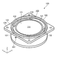
- FIG. 1 is a perspective view of a loudspeaker according to the present embodiment.
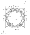
- FIG. 2 is a front view of the loudspeaker in the present exemplary embodiment.
- FIG. 3 is a cross-sectional view of the loudspeaker along line AA in FIG.
- FIG. 4 is a cross-sectional view of the loudspeaker along line BB in FIG.
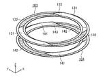
- FIG. 5 is a perspective view showing the front support and the rear support.
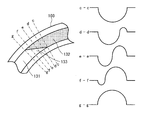
- FIG. 6 is a view showing a cross-sectional shape in the radial direction of the front connecting portion.
- FIG. 7 is a perspective view showing another example of the front support and the rear support.
- drawings are schematic diagrams in which emphasis, omission, and ratio adjustment are appropriately performed to show the present disclosure, and may differ from actual shapes, positional relationships, and ratios.
- a loudspeaker 100 that is one of electroacoustic transducers will be described as an example.
- the loudspeaker 100 is required to have various forms depending on applications.
- the loudspeaker 100 is thin to be installed in a narrow space such as a car dashboard, a car door, or a car ceiling. The loudspeaker 100 will be described.
- FIG. 1 is a perspective view of a loudspeaker according to the present embodiment.
- the dark color is attached
- FIG. 2 is a front view of the loudspeaker in the present embodiment.
- FIG. 3 is a cross-sectional view of the loudspeaker along line AA in FIG.
- FIG. 4 is a cross-sectional view of the loudspeaker along line BB in FIG.
- the loudspeaker 100 is an electroacoustic transducer that converts an electrical signal into sound, and includes a diaphragm 101, a frame 102, a front support 103 that is one support, and the other.
- a rear support 104, a magnetic circuit 105, and a voice coil 106 are provided.
- the diaphragm 101 is a member that vibrates air by being displaced in the front-rear direction (the Z-axis direction in the figure, the thickness direction of the diaphragm 101) based on the neutral position based on an electrical signal, and generates a sound. It has a front surface 111 arranged along the XY plane in the direction (Z axis positive side in the figure) and a rear surface 112 arranged in the XY plane in the rear side. In the case of the present embodiment, the peripheral portion of the diaphragm 101 is provided with a thick portion 113 that is relatively thicker than the central portion. The diaphragm 101 is disposed at the center of the hollow portion of the frame 102.
- the diaphragm 101 has a flat plate shape and is thinner than a cone-type diaphragm. As a result, the entire loudspeaker 100 can be thinned.
- the material which comprises the diaphragm 101 is not specifically limited,
- the diaphragm 101 formed with the core material made from a foamed resin can be illustrated. With this configuration, the diaphragm 101 can be lightened, and the response characteristics of the diaphragm 101 can be improved. Further, a reinforcing material layer made of aluminum, titanium, carbon or the like may be provided on the core material.
- the thick portion 113 is an annular portion that increases the structural strength of the diaphragm 101 and to which the front support 103 and the rear support 104 are attached.
- the thick portion 113 is formed integrally with the vibration plate 101.
- a separate thick portion 113 may be attached to the flat plate-like vibration plate by bonding or the like.
- the frame 102 is a member that is a structural basis of the loudspeaker 100, and is a cylindrical casing having a hollow portion inward.
- the frame 102 is disposed so as to surround the peripheral portion of the vibration plate 101, and is disposed at a position corresponding to the front portion of the thick portion 113 provided on the peripheral portion of the vibration plate 101 as shown in FIGS.
- the front ring part 121 and the rear ring part 122 disposed at a position corresponding to the rear part of the thick part 113 are provided.
- the front ring portion 121 and the rear ring portion 122 are the front surface and the rear surface of an annular flange that protrudes inward from the inner peripheral surface of the frame 102.
- the frame 102 has an attachment portion 123 as shown in FIGS. Since the frame 102 has the attachment portion 123, the loudspeaker 100 can be easily attached to a baffle plate (not shown) or the like by the attachment portion 123. Further, a screw hole 124 may be formed in the attachment portion 123. In this case, the loudspeaker 100 can be easily fixed to the baffle plate or the like through the screw hole 124 by screwing. Note that the frame 102 may not have the attachment portion 123.
- the frame 102 is preferably molded from a synthetic resin material.
- FIG. 5 is a perspective view showing the front support and the rear support.
- the front support 103 which is one support, is a member having flexibility and resiliency that connects the front portion of the thick portion 113 and the front ring portion 121 of the frame 102.
- the rear support 104 which is the other support, is a member having flexibility and resiliency for connecting the rear portion of the thick portion 113 and the rear ring portion 122 of the frame 102.
- the front side support body 103 and the rear side support body 104 are annular members arranged at intervals corresponding to the thickness of the thick portion 113.
- the support is a member that positions the diaphragm 101 in the center with respect to the frame 102 and places the diaphragm 101 in a neutral position when no electrical signal is supplied.
- the front support 103 includes a front convex portion 131 that bulges toward the front side (Z-axis positive side in the drawing) and a front concave portion 132 that bulges toward the rear side (Z-axis negative side in the drawing). A plurality of locations (two in the case of the present embodiment) are provided.
- the rear support 104 includes a rear convex portion 141 that bulges toward the front side and a rear concave portion 142 that bulges toward the rear side, each at a plurality of locations (two in the present embodiment). ing.
- the vibration of the vibration plate 101 can be made uniform between the front side and the rear side, and further on the front side and the rear side. Since the amount of excluded air can be made uniform, distortion can be reduced.
- front support body 103 and the rear support body 104 have an annular inner mounting portion with a rectangular cross section attached to the thick portion 113 of the diaphragm 101 and a rectangular cross section attached to the frame 102. And an annular outer mounting portion.
- the cross-sectional shape cut in the radial direction of the front convex portion 131 and the cross-sectional shape cut in the radial direction of the front concave portion 132 have a symmetrical structure in the front-rear direction (Z-axis direction in the figure). Further, in plan view (the state shown in FIG. 2), the area occupied by the front convex portion 131 and the area occupied by the front concave portion 132 are the same, that is, the radial length of the front convex portion 131 and the radial direction of the front concave portion 132. Are the same length. That is, the volume of the front convex part 131 and the volume of the front concave part 132 are the same.
- front convex portion 131 and the front concave portion 132 are connected by a front side connecting portion 133 which is one of the connecting portions in which the section cut in the radial direction gradually changes.
- FIG. 6 is a diagram showing the cross-sectional shape of the connecting portion in the radial direction.
- the front connecting part 133 that is one connecting part is a part that connects the front convex part 131 that is a convex part and the front concave part 132 that is a concave part, and the radial section has a convex shape. It is composed of two concave shapes.
- the front connecting portion 133 has a radial sectional length of the front convex portion 131 (the length of the curve (circumferential length) in the gg cross section in FIG. 6), or the radial sectional length of the front concave portion 132 (see FIG. 6 is a radial cross-sectional length (circumferential length) in the dd, ee, and ff cross-section in FIG. )have.
- the cross-sectional length of the connecting portion is desirably 115% or less of the cross-sectional length of the convex portion or the concave portion. 110% or less is particularly suitable.
- the cross-sectional length in the radial direction of the connecting portion at the central portion in the circumferential direction is longer than the end portion toward the central portion. It gradually becomes longer.
- the cross-sectional shape of the front convex portion 131 or the front concave portion 132 is a semicircular arc
- the cross-sectional shape of the front connecting portion 133 is formed by an elliptical arc, a hyperbola, a parabola, or the like.
- the concave shape of the front connecting portion 133 gradually decreases as the front concave portion 132 approaches the front convex portion 131.
- the convex shape of the front connecting portion 133 gradually increases as the front concave portion 132 approaches the front convex portion 131.
- the rear side support body 104 is provided with the rear side connection part 143 as the other connection part, and has a plane-symmetrical relationship with the front side connection part 133.
- the connecting portion may be pulled when the diaphragm 101 vibrates, and sound distortion may occur.
- the cross-sectional length of the connecting portion is longer than the cross-sectional length of the convex portion or the concave portion, the pulling of the connecting portion is suppressed, and the generation of sound distortion can be suppressed.
- the generation of distortion can be further suppressed by gradually increasing the cross-sectional length of the connecting portion from the end portion toward the central portion.
- cross-sectional shape of a convex part or a recessed part is not specifically limited, An arc, an elliptical arc, a parabola shape etc. may be sufficient.
- the front support 103 and the rear support 104 are such that the front convex portion 131 and the rear concave portion 142 face each other, and as shown in FIGS. It arrange
- the front support body 103 and the rear support body 104 are arranged in plane symmetry with the XY plane as the symmetry plane. That is, since the diaphragm 101 is supported by two structurally plane-symmetrical supports, the stiffness can be made symmetric in the front-rear direction, and the occurrence of distortion can be greatly suppressed. In addition, it is possible to suppress rolling of the diaphragm 101 caused by structural asymmetry.
- a wide space can be secured between the front support body 103 and the rear support body 104, and the lead wire 171 connecting the electrode terminal 107 and the voice coil body 106 to the space. Can be wired. Thereby, the loudspeaker 100 can be reduced in thickness.
- the lead wire 171 since the length of the lead wire 171 can be sufficiently secured, the lead wire 171 can be made to follow the amplitude of the vibration plate 101, and disconnection of the lead wire 171 can be avoided.
- the two pairs of the front convex portion 131 and the rear concave portion 142 facing each other are arranged in a rotational symmetry of 180 degrees, and are attached in an inserted state from the inside of the frame 102 to the outside. Since the two electrode terminals 107 connected to each other are disposed between the front convex portion 131 and the rear concave portion 142 that exist at two positions in a 180 degree relationship, the voice coil body 106 is connected to the lead coil 171 from the lead wire 171.
- the receiving force can be made uniform, and the occurrence of sound distortion can be suppressed.
- a sufficient space between the front support body 103 and the rear support body 104 is ensured by the thick part 113 of the vibration plate 101 and the front ring part 121 and the rear ring part 122 of the frame 102 corresponding thereto.
- the front concave portion 132, the rear support 104, and the rear convex portion 141 of the front support body 103 facing each other are prevented from colliding with each other. Therefore, it is possible to prevent the collision sound between the front support member 103 and the rear support member 104 from being generated, and it is possible to generate a high-quality sound with less distortion.
- the material which comprises the front side support body 103 and the back side support body 104 is not specifically limited, For example, what is necessary is just the material provided with the softness
- the magnetic circuit 105 is a component that acts on the magnetic flux generated in the voice coil body 106 based on the electrical signal and displaces the voice coil body 106 back and forth. As shown in FIGS. This is a component that has an annular magnetic gap 151 facing 112 and is fixed to the frame 102.
- the magnetic circuit 105 is an internal magnet type, magnetized in the front-rear direction, a magnet columnar magnet 152, a disk-shaped top plate 153 disposed on the upper surface of the magnet 152, and the top plate And a bottomed cylindrical yoke 154 disposed so as to surround 153.
- the top plate 153 and the yoke 154 are made of a magnetic material.
- the magnet 152 for example, a neodymium magnet having a high magnetic flux density is preferably used. Thereby, the thickness of the magnet 152 can be reduced and the thickness of the entire loudspeaker 100 can be reduced.
- the inner peripheral surface of the yoke 154 is disposed so as to face the outer peripheral surface of the top plate 153 at a predetermined interval.
- a magnetic gap 151 is formed between the inner peripheral surface of the yoke 154 and the outer peripheral side surface of the top plate 153. Is formed.
- the outer peripheral surface of the yoke 154 is tapered in order to avoid interference with the thick portion 113 when the vibration plate 101 vibrates.
- the voice coil body 106 is a component whose rear end is disposed in the magnetic gap 151 of the magnetic circuit 105, and whose front end is connected to the diaphragm 101.
- the voice coil body 106 generates magnetic flux based on an input electric signal, It is a component that can vibrate in the front-rear direction by interaction with the magnetic circuit 105.
- the winding axis (center axis) of the voice coil body 106 is arranged in the vibration (amplitude) direction (Z-axis direction in the drawing) of the diaphragm 101 and is orthogonal to the direction of the magnetic flux in the magnetic gap 151.
- the voice coil body 106 includes a bobbin and a coil wound around the bobbin.
- the bobbin is a cylindrical member made of a material such as aluminum or resin.
- the front end is coupled to the vibration plate 101 and the rear end is disposed in the magnetic gap 151.
- the voice coil body 106 is coupled to the center of the diaphragm 101 where the thickness is relatively thin. Further, the upper portion of the magnetic circuit 105 is disposed at a position surrounded by the thick portion 113. As a result, the distance between the magnetic circuit 105 and the diaphragm 101 can be reduced, and the thickness of the loudspeaker 100 can be reduced.
- the front support body 103 including the front convex portion 131 and the front concave portion 132, and the rear support body 104 including the rear convex portion 141 and the rear concave portion 142 are arranged on the diaphragm 101. It operates as a support for the diaphragm 101 without hindering the amplitude motion in the front-rear direction, and acoustically shields the sound emitted from the back surface of the diaphragm 101 together with the front support 103 and the rear support 104.
- the amount of air removed by the front convex portion 131 and the front concave portion 132 is the sum of the amount of air removed and when the diaphragm 101 is displaced rearward from the neutral position.
- the sum of the air removal amount of the front convex portion 131 and the air discharge amount of the front concave portion 132 is equal.
- the rear support 104 That is, even when the vibration plate 101 swings in the front-rear direction, there is no asymmetry in the amount of excluded air, and the occurrence of sound distortion can be suppressed.
- the present disclosure can avoid a state in which the connecting portion is pulled due to the displacement of the diaphragm by making the cross-sectional length of the connecting portion in the radial direction longer than the cross-sectional length of the convex portion or the concave portion. Therefore, it is possible to avoid the distortion that occurs when the connecting portion pulls and obstructs the displacement of the vibration plate 101.
- the diaphragm 101 is supported by the front support 103 having a front convex portion 131 and a front concave portion 132 that are symmetrical in the front-rear direction and rotational symmetry, and the rear support 104 that is plane-symmetric with the front support 103. Therefore, the amount of air removed by the front support 103 and the amount of air removed by the rear support 104 can be made the same with respect to the amplitude of the vibration plate 101 in the front-rear direction, and in the amplitude direction. Regardless of this, it is possible to make the amount of air excluded constant. Therefore, it is possible to greatly reduce the occurrence of distortion due to the asymmetry of the amount of air excluded by the support that has been generated conventionally. In addition, it is possible to provide the loudspeaker 100 with extremely low distortion and high input resistance such that the asymmetry of the support force due to the asymmetry of the support structure can be improved.
- a thick portion 113 is provided at the peripheral portion of the plate-like diaphragm 101 to ensure the structural strength of the diaphragm 101 and the front portion of the magnetic circuit 105 is disposed inside the annular thick portion 113.
- the thickness of the loudspeaker 100 can be reduced. As a result, a thin loudspeaker having a high sound pressure level and a small distortion can be provided.
- the present disclosure is not limited to the above embodiment.
- another embodiment realized by arbitrarily combining the components described in this specification and excluding some of the components may be used as an embodiment of the present disclosure.
- the present disclosure also includes modifications obtained by making various modifications conceivable by those skilled in the art without departing from the gist of the present disclosure, that is, the meanings of the words described in the claims. It is.
- a loudspeaker is exemplified, but the electroacoustic transducer may be a microphone or a sensor that converts sound into an electric signal.
- the front support body 103 and the rear support body 104 each having two convex portions and concave portions are illustrated, but the number of convex portions and concave portions is not limited to this, As shown in FIG. 7, you may provide more than three each.
- the shapes of the diaphragm 101, the magnetic circuit 105, and the voice coil body 106 have been described as circular in plan view, the shape is not limited to this, and the elliptical shape or rectangular shape in plan view may be used.
- the magnetic circuit 105 is not limited to the inner magnet type magnetic circuit 105, and may be an outer magnet type or a structure in which the inner magnet type and the outer magnet type are combined.
- any magnet such as a samarium iron magnet or a ferrite magnet can be adopted.
- the electroacoustic transducer according to the present disclosure can realize low distortion, and can be used particularly for an acoustic device mounted on an automobile or a household acoustic device.
Abstract
L'invention concerne un transducteur électro-acoustique comportant: une plaque vibrante; un cadre disposé de façon à entourer la circonférence de la plaque vibrante; un support qui relie la plaque vibrante et le cadre et qui possède une protubérance qui fait saillie vers le côté avant, un retrait qui se creuse vers le côté arrière, et une partie liaison qui relie la protubérance et le retrait; un circuit magnétique; et une bobine mobile. En outre, la partie liaison présente une longueur de section transversale en direction radiale supérieure à la longueur de section transversale en direction radiale de la protubérance ou du retrait.
Applications Claiming Priority (2)
| Application Number | Priority Date | Filing Date | Title |
|---|---|---|---|
| JP2015-246803 | 2015-12-17 | ||
| JP2015246803A JP2019024149A (ja) | 2015-12-17 | 2015-12-17 | 電気音響変換器 |
Publications (1)
| Publication Number | Publication Date |
|---|---|
| WO2017104125A1 true WO2017104125A1 (fr) | 2017-06-22 |
Family
ID=59056178
Family Applications (1)
| Application Number | Title | Priority Date | Filing Date |
|---|---|---|---|
| PCT/JP2016/005103 WO2017104125A1 (fr) | 2015-12-17 | 2016-12-12 | Transducteur électro-acoustique |
Country Status (2)
| Country | Link |
|---|---|
| JP (1) | JP2019024149A (fr) |
| WO (1) | WO2017104125A1 (fr) |
Citations (3)
| Publication number | Priority date | Publication date | Assignee | Title |
|---|---|---|---|---|
| JPS5656095A (en) * | 1979-10-12 | 1981-05-16 | Hitachi Ltd | Plane loudspeaker |
| JPH06178388A (ja) * | 1992-12-11 | 1994-06-24 | Matsushita Electric Ind Co Ltd | スピーカ |
| JP2001128284A (ja) * | 1999-11-01 | 2001-05-11 | Foster Electric Co Ltd | 電気音響変換器 |
-
2015
- 2015-12-17 JP JP2015246803A patent/JP2019024149A/ja active Pending
-
2016
- 2016-12-12 WO PCT/JP2016/005103 patent/WO2017104125A1/fr active Application Filing
Patent Citations (3)
| Publication number | Priority date | Publication date | Assignee | Title |
|---|---|---|---|---|
| JPS5656095A (en) * | 1979-10-12 | 1981-05-16 | Hitachi Ltd | Plane loudspeaker |
| JPH06178388A (ja) * | 1992-12-11 | 1994-06-24 | Matsushita Electric Ind Co Ltd | スピーカ |
| JP2001128284A (ja) * | 1999-11-01 | 2001-05-11 | Foster Electric Co Ltd | 電気音響変換器 |
Also Published As
| Publication number | Publication date |
|---|---|
| JP2019024149A (ja) | 2019-02-14 |
Similar Documents
| Publication | Publication Date | Title |
|---|---|---|
| JP4912922B2 (ja) | スピーカ | |
| US10932050B2 (en) | Micro-speaker | |
| US9485582B2 (en) | Speaker | |
| CN110178383B (zh) | 桥型边缘方式的高分辨率电磁扬声器 | |
| US10334367B2 (en) | Electroacoustic transducer | |
| US9756426B2 (en) | Loudspeaker | |
| WO2017104124A1 (fr) | Transducteur électro-acoustique | |
| JP4768823B2 (ja) | スピーカ | |
| JP6194741B2 (ja) | 動電型スピーカー | |
| US10820111B2 (en) | Acoustic membrane for a loudspeaker and corresponding loudspeaker | |
| WO2017104125A1 (fr) | Transducteur électro-acoustique | |
| JP4042732B2 (ja) | リング型スピーカー | |
| JP6253101B2 (ja) | 動電型電気音響変換器、及びその振動板、並びに動電型電気音響変換器の製造方法 | |
| JP4440001B2 (ja) | スピーカ | |
| JP2014003470A (ja) | スピーカ装置 | |
| JP2009159009A (ja) | スピーカ | |
| JP6989751B2 (ja) | ダストキャップおよびこれを用いる動電型スピーカー | |
| JP4962712B2 (ja) | リング型スピーカーおよびこれを用いたスピーカーシステム | |
| JP5278045B2 (ja) | スピーカ | |
| JP5198123B2 (ja) | スピーカ | |
| US20220416634A1 (en) | Separate coil mounting structure of coaxial exciter | |
| JP2016072914A (ja) | 動電型スピーカー | |
| JP6436530B2 (ja) | 動電型電気音響変換器及びその製造方法 | |
| WO2019087375A1 (fr) | Dispositif haut-parleur | |
| JP2005012694A (ja) | 平面スピーカ |
Legal Events
| Date | Code | Title | Description |
|---|---|---|---|
| 121 | Ep: the epo has been informed by wipo that ep was designated in this application |
Ref document number: 16875114 Country of ref document: EP Kind code of ref document: A1 |
|
| NENP | Non-entry into the national phase |
Ref country code: DE |
|
| 122 | Ep: pct application non-entry in european phase |
Ref document number: 16875114 Country of ref document: EP Kind code of ref document: A1 |
|
| NENP | Non-entry into the national phase |
Ref country code: JP |