WO2017104125A1 - Electroacoustic transducer - Google Patents
Electroacoustic transducer Download PDFInfo
- Publication number
- WO2017104125A1 WO2017104125A1 PCT/JP2016/005103 JP2016005103W WO2017104125A1 WO 2017104125 A1 WO2017104125 A1 WO 2017104125A1 JP 2016005103 W JP2016005103 W JP 2016005103W WO 2017104125 A1 WO2017104125 A1 WO 2017104125A1
- Authority
- WO
- WIPO (PCT)
- Prior art keywords
- diaphragm
- electroacoustic transducer
- support
- convex
- frame
- Prior art date
Links
Images


Classifications
-
- H—ELECTRICITY
- H04—ELECTRIC COMMUNICATION TECHNIQUE
- H04R—LOUDSPEAKERS, MICROPHONES, GRAMOPHONE PICK-UPS OR LIKE ACOUSTIC ELECTROMECHANICAL TRANSDUCERS; DEAF-AID SETS; PUBLIC ADDRESS SYSTEMS
- H04R7/00—Diaphragms for electromechanical transducers; Cones
- H04R7/02—Diaphragms for electromechanical transducers; Cones characterised by the construction
- H04R7/04—Plane diaphragms
-
- H—ELECTRICITY
- H04—ELECTRIC COMMUNICATION TECHNIQUE
- H04R—LOUDSPEAKERS, MICROPHONES, GRAMOPHONE PICK-UPS OR LIKE ACOUSTIC ELECTROMECHANICAL TRANSDUCERS; DEAF-AID SETS; PUBLIC ADDRESS SYSTEMS
- H04R7/00—Diaphragms for electromechanical transducers; Cones
- H04R7/16—Mounting or tensioning of diaphragms or cones
- H04R7/18—Mounting or tensioning of diaphragms or cones at the periphery
- H04R7/20—Securing diaphragm or cone resiliently to support by flexible material, springs, cords, or strands
-
- H—ELECTRICITY
- H04—ELECTRIC COMMUNICATION TECHNIQUE
- H04R—LOUDSPEAKERS, MICROPHONES, GRAMOPHONE PICK-UPS OR LIKE ACOUSTIC ELECTROMECHANICAL TRANSDUCERS; DEAF-AID SETS; PUBLIC ADDRESS SYSTEMS
- H04R9/00—Transducers of moving-coil, moving-strip, or moving-wire type
- H04R9/02—Details
-
- H—ELECTRICITY
- H04—ELECTRIC COMMUNICATION TECHNIQUE
- H04R—LOUDSPEAKERS, MICROPHONES, GRAMOPHONE PICK-UPS OR LIKE ACOUSTIC ELECTROMECHANICAL TRANSDUCERS; DEAF-AID SETS; PUBLIC ADDRESS SYSTEMS
- H04R9/00—Transducers of moving-coil, moving-strip, or moving-wire type
- H04R9/02—Details
- H04R9/04—Construction, mounting, or centering of coil
Abstract
This electroacoustic transducer is provided with: a diaphragm; a frame disposed so as to surround the diaphragm; a support which couples the diaphragm and the frame, and which is provided with a protruded portion which protrudes towards the front side, a recessed portion which protrudes towards the rear side, and a connecting portion which connects the protruded portion and the recessed portion; a magnetic circuit; and a voice coil body. Furthermore, the connecting portion has a cross-sectional length in the radial direction which is longer than that of the protruded portion or that of the recessed portion.
Description
本開示は、ラウドスピーカやマイクロフォンなど電気信号を音に変換する、または、音を電気信号に変換する電気音響変換器に関する。
The present disclosure relates to an electroacoustic transducer that converts an electrical signal into sound, such as a loudspeaker or a microphone, or converts sound into an electrical signal.
近年、デジダル信号処理技術が飛躍的に進歩し、音声信号の質が大幅に向上したため、これに対応して高音質再生の可能なラウドスピーカや、音を歪みなく正確に電気信号に変換するマイクロフォンなどの電気音響変換器が望まれている。
In recent years, digital signal processing technology has dramatically improved, and the quality of audio signals has been greatly improved. Correspondingly, loudspeakers that can reproduce high-quality sound and microphones that accurately convert sound into electrical signals without distortion Such an electroacoustic transducer is desired.
一方、電気音響変換器の薄型化も望まれており、例えば、特許文献1に記載のように、振動により音を発生させ、また、音の振動に伴って振動する振動板を平板状とすることにより薄型化を実現している電気音響変換器が存在している。
On the other hand, it is also desired to reduce the thickness of the electroacoustic transducer. For example, as described in Patent Document 1, sound is generated by vibration, and the vibration plate that vibrates with sound vibration is flat. Therefore, there are electroacoustic transducers that are thinned.
この様な従来の電気音響変換器では、振動板の振幅が大きくなる低音域において、フレームに対して振動板を支持する支持体が高調波歪などの発生要因となる場合がある。つまり振動板が大振幅した場合に、支持体が振動板の振幅に追随しきれずにつっぱり、これが高周波歪の原因となるという問題がある。
In such a conventional electroacoustic transducer, the support body that supports the diaphragm with respect to the frame may cause harmonic distortion or the like in a low sound range where the amplitude of the diaphragm increases. That is, when the diaphragm has a large amplitude, there is a problem in that the support member cannot keep up with the amplitude of the diaphragm and this causes high frequency distortion.
また、振動板は、中立点より前側、および、後側に振動し、振動板を支える支持体もこれに伴って振動する。しかし、中立点の位置から前側に向かって振動板が移動する際に支持体が排除する空気量と、中立点の位置から後側に向かって振動板が移動する際に支持体が排除する空気量とが相違する。このように排除する空気量が外向きと内向きとの動きによって異なる場合、電気音響変換器の音圧特性は歪成分を含んだものとなる。
Also, the diaphragm vibrates forward and rearward from the neutral point, and the support that supports the diaphragm vibrates accordingly. However, the amount of air that the support excludes when the diaphragm moves from the neutral point toward the front side and the air that the support excludes when the diaphragm moves from the neutral point toward the rear side. The amount is different. When the amount of air to be excluded differs depending on the outward movement and the inward movement, the sound pressure characteristic of the electroacoustic transducer includes a distortion component.
本開示は上記課題に鑑みなされたものであり、高調波歪などの歪の発生を大幅に低減させた電気音響変換器の提供を目的としている。
The present disclosure has been made in view of the above problems, and an object thereof is to provide an electroacoustic transducer in which generation of distortion such as harmonic distortion is significantly reduced.
上記目的を達成するために、本開示にかかる電気音響変換器は、電気信号と音とを相互に変換する電気音響変換器であって、前側に向く前方面と後側に向く後方面とを有する振動板と、振動板の周縁部を囲むように配置されるフレームと、振動板の周縁部とフレームとを結合し、前側に向かって膨出する凸部、後側に向かって膨出する凹部、および、凸部と凹部とを連結する連結部を有する支持体と、振動板の後方面に対向する環状の磁気ギャップを有し、フレームに固定される磁気回路と、後側端部が磁気ギャップ内に配置され、前側端部が振動板に結合されるボイスコイル体とを備え、連結部は、凸部の径方向の断面長さ、または、凹部の径方向の断面長さよりも長い径方向の断面長さを有することを特徴としている。
In order to achieve the above object, an electroacoustic transducer according to the present disclosure is an electroacoustic transducer that mutually converts an electric signal and sound, and includes a front surface facing the front side and a rear surface facing the rear side. The diaphragm having the diaphragm, the frame disposed so as to surround the peripheral edge of the diaphragm, the peripheral edge of the diaphragm and the frame, and the convex portion bulging toward the front side, and bulging toward the rear side. A support having a recess, and a connecting portion for connecting the projection and the recess, a magnetic circuit having an annular magnetic gap facing the rear surface of the diaphragm, fixed to the frame, and a rear end portion A voice coil body that is disposed in the magnetic gap and whose front end is coupled to the diaphragm, and the connecting portion is longer than the radial cross-sectional length of the convex portion or the radial cross-sectional length of the concave portion It has a cross-sectional length in the radial direction.
本開示によれば、歪の発生を大幅に低減させた電気音響変換器を実現することが可能となる。
According to the present disclosure, it is possible to realize an electroacoustic transducer that greatly reduces the occurrence of distortion.
次に、本開示に係る電気音響変換器の実施の形態について、図面を参照しつつ説明する。なお、以下の実施の形態は、本開示に係る電気音響変換器の一例を示したものに過ぎない。従って本開示は、以下の実施の形態を参考に請求の範囲の文言によって範囲が画定されるものであり、以下の実施の形態のみに限定されるものではない。よって、以下の実施の形態における構成要素のうち、本開示の最上位概念を示す独立請求項に記載されていない構成要素については、本開示の課題を達成するのに必ずしも必要ではないが、より好ましい形態を構成するものとして説明される。
Next, an embodiment of an electroacoustic transducer according to the present disclosure will be described with reference to the drawings. The following embodiments are merely examples of the electroacoustic transducer according to the present disclosure. Accordingly, the scope of the present disclosure is defined by the wording of the claims with reference to the following embodiments, and is not limited to the following embodiments. Therefore, among the constituent elements in the following embodiments, constituent elements that are not described in the independent claims indicating the highest concept of the present disclosure are not necessarily required to achieve the object of the present disclosure. It will be described as constituting a preferred form.
また、図面は、本開示を示すために適宜強調や省略、比率の調整を行った模式的な図となっており、実際の形状や位置関係、比率とは異なる場合がある。
In addition, the drawings are schematic diagrams in which emphasis, omission, and ratio adjustment are appropriately performed to show the present disclosure, and may differ from actual shapes, positional relationships, and ratios.
本実施の形態の場合、電気音響変換器の一つであるラウドスピーカ100を例示して説明する。ラウドスピーカ100は、用途によって種々の形態が要求されるが、本実施の形態の場合、たとえば、車のダッシュボードや、車のドアや、車の天井などの狭い空間内に設置するための薄いラウドスピーカ100について説明する。
In the case of this embodiment, a loudspeaker 100 that is one of electroacoustic transducers will be described as an example. The loudspeaker 100 is required to have various forms depending on applications. In the case of the present embodiment, for example, the loudspeaker 100 is thin to be installed in a narrow space such as a car dashboard, a car door, or a car ceiling. The loudspeaker 100 will be described.
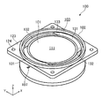
図1は、本実施の形態におけるラウドスピーカの斜視図である。なお、図に示す凹部については、濃い色を付して示している。
FIG. 1 is a perspective view of a loudspeaker according to the present embodiment. In addition, about the recessed part shown to a figure, the dark color is attached | subjected and shown.
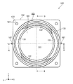
図2は、本実施の形態におけるラウドスピーカの正面図である。
FIG. 2 is a front view of the loudspeaker in the present embodiment.
図3は、図2の線A-Aにおけるラウドスピーカの断面図である。
FIG. 3 is a cross-sectional view of the loudspeaker along line AA in FIG.
図4は、図2の線B-Bにおけるラウドスピーカの断面図である。
FIG. 4 is a cross-sectional view of the loudspeaker along line BB in FIG.
これらの図に示すように、ラウドスピーカ100は、電気信号を音に変換する電気音響変換器であって、振動板101と、フレーム102と、一方の支持体である前側支持体103と、他方の支持体である後側支持体104と、磁気回路105と、ボイスコイル体106とを備えている。
As shown in these drawings, the loudspeaker 100 is an electroacoustic transducer that converts an electrical signal into sound, and includes a diaphragm 101, a frame 102, a front support 103 that is one support, and the other. A rear support 104, a magnetic circuit 105, and a voice coil 106 are provided.
振動板101は、電気信号に基づき中立位置を基準に前後方向(図中Z軸方向、振動板101の厚み方向)に変位することにより空気を振動させ、音を発生させる部材であり、前側(図中Z軸正側)に向きXY平面に沿って配置される前方面111と後側に向きXY平面に沿って配置される後方面112とを有している。本実施の形態の場合、振動板101の周縁部には中央部よりも肉厚が比較的厚い肉厚部113を備えている。振動板101は、フレーム102の中空部分の中央に配置されている。
The diaphragm 101 is a member that vibrates air by being displaced in the front-rear direction (the Z-axis direction in the figure, the thickness direction of the diaphragm 101) based on the neutral position based on an electrical signal, and generates a sound. It has a front surface 111 arranged along the XY plane in the direction (Z axis positive side in the figure) and a rear surface 112 arranged in the XY plane in the rear side. In the case of the present embodiment, the peripheral portion of the diaphragm 101 is provided with a thick portion 113 that is relatively thicker than the central portion. The diaphragm 101 is disposed at the center of the hollow portion of the frame 102.
本実施の形態の場合、振動板101は、平板状となっており、コーン型の振動板に比べて薄い形状となっている。これによりラウドスピーカ100全体を薄くすることが可能となる。
In the case of the present embodiment, the diaphragm 101 has a flat plate shape and is thinner than a cone-type diaphragm. As a result, the entire loudspeaker 100 can be thinned.
振動板101を構成する材料は特に限定されるものではないが、例えば、発泡樹脂製の芯材により形成される振動板101を例示できる。この構成により、振動板101を軽くすることができ、振動板101の応答特性を向上させることが可能となる。さらに、芯材に、アルミや、チタン、あるいはカーボンなどからなる補強材層を設けてもかまわない。
Although the material which comprises the diaphragm 101 is not specifically limited, For example, the diaphragm 101 formed with the core material made from a foamed resin can be illustrated. With this configuration, the diaphragm 101 can be lightened, and the response characteristics of the diaphragm 101 can be improved. Further, a reinforcing material layer made of aluminum, titanium, carbon or the like may be provided on the core material.
肉厚部113は、振動板101の構造的強度を高め、前側支持体103および後側支持体104が取り付けられる環状の部分である。本実施の形態の場合、肉厚部113は、振動板101と一体に形成されているが、平板状の振動板に別体の肉厚部113を接着などにより取り付けるものでもかまわない。
The thick portion 113 is an annular portion that increases the structural strength of the diaphragm 101 and to which the front support 103 and the rear support 104 are attached. In the case of the present embodiment, the thick portion 113 is formed integrally with the vibration plate 101. However, a separate thick portion 113 may be attached to the flat plate-like vibration plate by bonding or the like.
フレーム102は、ラウドスピーカ100の構造的基礎となる部材であり、内方に中空部を有する筒状の筐体である。フレーム102は、振動板101の周縁部を囲むように配置され、図3、図4に示すように、振動板101の周縁部に設けられる肉厚部113の前方部と対応する位置に配置される前側環部121と、肉厚部113の後方部と対応する位置に配置される後側環部122とを備えている。本実施の形態の場合、前側環部121と後側環部122は、フレーム102の内周面から内方に向かって突出する環状のフランジの前面と後面である。
The frame 102 is a member that is a structural basis of the loudspeaker 100, and is a cylindrical casing having a hollow portion inward. The frame 102 is disposed so as to surround the peripheral portion of the vibration plate 101, and is disposed at a position corresponding to the front portion of the thick portion 113 provided on the peripheral portion of the vibration plate 101 as shown in FIGS. The front ring part 121 and the rear ring part 122 disposed at a position corresponding to the rear part of the thick part 113 are provided. In the case of the present embodiment, the front ring portion 121 and the rear ring portion 122 are the front surface and the rear surface of an annular flange that protrudes inward from the inner peripheral surface of the frame 102.
本実施の形態の場合、フレーム102は、図1、図2に示すように、取付部123を有している。フレーム102が取付部123を有することにより、ラウドスピーカ100は、取付部123によりバッフル板(図示せず)などへ容易に装着することができる。また、取付部123にネジ孔124が形成されていても良い。この場合、ラウドスピーカ100は、ネジ孔124を通してバッフル板などにねじ止めによって容易に固定することができる。なお、フレーム102は、取付部123を有していなくてもよい。また、フレーム102は合成樹脂材料により成形されるのが好ましい。
In the case of the present embodiment, the frame 102 has an attachment portion 123 as shown in FIGS. Since the frame 102 has the attachment portion 123, the loudspeaker 100 can be easily attached to a baffle plate (not shown) or the like by the attachment portion 123. Further, a screw hole 124 may be formed in the attachment portion 123. In this case, the loudspeaker 100 can be easily fixed to the baffle plate or the like through the screw hole 124 by screwing. Note that the frame 102 may not have the attachment portion 123. The frame 102 is preferably molded from a synthetic resin material.
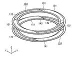
図5は、前側支持体と後側支持体を示す斜視図である。
FIG. 5 is a perspective view showing the front support and the rear support.
一方の支持体である前側支持体103は、肉厚部113の前方部とフレーム102の前側環部121とを接続する柔軟性および復元性を備えた部材である。また、他方の支持体である後側支持体104は、肉厚部113の後方部とフレーム102の後側環部122とを接続する柔軟性および復元性を備えた部材である。前側支持体103と、後側支持体104とは肉厚部113の厚みに対応する間隔で配置される環状の部材である。支持体は、フレーム102に対して振動板101を中央に位置させ、電気信号が供給されていない状態では、振動板101を中立の位置に配置する部材である。
The front support 103, which is one support, is a member having flexibility and resiliency that connects the front portion of the thick portion 113 and the front ring portion 121 of the frame 102. The rear support 104, which is the other support, is a member having flexibility and resiliency for connecting the rear portion of the thick portion 113 and the rear ring portion 122 of the frame 102. The front side support body 103 and the rear side support body 104 are annular members arranged at intervals corresponding to the thickness of the thick portion 113. The support is a member that positions the diaphragm 101 in the center with respect to the frame 102 and places the diaphragm 101 in a neutral position when no electrical signal is supplied.
また、前側支持体103は、前側(図中Z軸正側)に向かって膨出する前側凸部131と後側(図中Z軸負側)に向かって膨出する前側凹部132とをそれぞれ複数箇所(本実施の形態の場合二箇所ずつ)備えている。後側支持体104は、前側に向かって膨出する後側凸部141と後側に向かって膨出する後側凹部142とをそれぞれ複数箇所(本実施の形態の場合二箇所ずつ)に備えている。前側支持体103、および、後側支持体104がそれぞれ凸部と凹部とを備えることにより、振動板101の振動を前側と後側とで均等にすることができ、さらに前側と後側とで空気の排除量も均等にすることができるため、歪を低減させることができる。
The front support 103 includes a front convex portion 131 that bulges toward the front side (Z-axis positive side in the drawing) and a front concave portion 132 that bulges toward the rear side (Z-axis negative side in the drawing). A plurality of locations (two in the case of the present embodiment) are provided. The rear support 104 includes a rear convex portion 141 that bulges toward the front side and a rear concave portion 142 that bulges toward the rear side, each at a plurality of locations (two in the present embodiment). ing. Since the front support body 103 and the rear support body 104 are each provided with a convex portion and a concave portion, the vibration of the vibration plate 101 can be made uniform between the front side and the rear side, and further on the front side and the rear side. Since the amount of excluded air can be made uniform, distortion can be reduced.
また、前側支持体103、および、後側支持体104は、振動板101の肉厚部113に取り付けられる径方向の断面が矩形の円環状の内側取付部と、フレーム102に取り付けられる断面矩形の円環状の外側取付部とを備えている。
In addition, the front support body 103 and the rear support body 104 have an annular inner mounting portion with a rectangular cross section attached to the thick portion 113 of the diaphragm 101 and a rectangular cross section attached to the frame 102. And an annular outer mounting portion.
前側凸部131の径方向に切断した断面形状と前側凹部132の径方向に切断した断面形状は前後方向(図中Z軸方向)に対称構造となっている。また、平面視(図2に示す状態)において、前側凸部131が占める面積と前側凹部132が占める面積とは同じ、つまり、前側凸部131の径方向の長さと、前側凹部132の径方向の長さは同じになっている。すなわち前側凸部131の体積と前側凹部132の体積とは一致する。
The cross-sectional shape cut in the radial direction of the front convex portion 131 and the cross-sectional shape cut in the radial direction of the front concave portion 132 have a symmetrical structure in the front-rear direction (Z-axis direction in the figure). Further, in plan view (the state shown in FIG. 2), the area occupied by the front convex portion 131 and the area occupied by the front concave portion 132 are the same, that is, the radial length of the front convex portion 131 and the radial direction of the front concave portion 132. Are the same length. That is, the volume of the front convex part 131 and the volume of the front concave part 132 are the same.
また、前側凸部131と前側凹部132とは、その間を径方向に切断した断面が徐々に連続して変化する連結部の一つである前側連結部133によって接続されている。
Further, the front convex portion 131 and the front concave portion 132 are connected by a front side connecting portion 133 which is one of the connecting portions in which the section cut in the radial direction gradually changes.
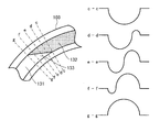
図6は、連結部の径方向の断面形状をそれぞれ示す図である。
FIG. 6 is a diagram showing the cross-sectional shape of the connecting portion in the radial direction.
同図に示すように、一方の連結部である前側連結部133は、凸部である前側凸部131と凹部である前側凹部132とを連結する部分であり、径方向の断面が凸形状と凹形状の2つの形状から構成されている。前側連結部133は、前側凸部131の径方向の断面長さ(図6中g-g断面における曲線の長さ(周長))、または、前側凹部132の径方向の断面長さ(図6中c-c断面における曲線の長さ(周長))よりも長い径方向の断面長さ(図6中d-d、e-e、f-f断面における曲線の長さ(周長))を有している。
As shown in the figure, the front connecting part 133 that is one connecting part is a part that connects the front convex part 131 that is a convex part and the front concave part 132 that is a concave part, and the radial section has a convex shape. It is composed of two concave shapes. The front connecting portion 133 has a radial sectional length of the front convex portion 131 (the length of the curve (circumferential length) in the gg cross section in FIG. 6), or the radial sectional length of the front concave portion 132 (see FIG. 6 is a radial cross-sectional length (circumferential length) in the dd, ee, and ff cross-section in FIG. )have.
ここで、連結部の断面長さは、凸部、または、凹部の断面長さの115%以下が望ましい。特に110%以下が適している。
Here, the cross-sectional length of the connecting portion is desirably 115% or less of the cross-sectional length of the convex portion or the concave portion. 110% or less is particularly suitable.
さらに本実施の形態の場合、周方向の中央部における前記連結部の径方向の断面長さ(図6中e-e断面における曲線の長さ(周長))は、周方向の両端部における前記連結部の径方向の断面長さ(図6中d-d、または、f-f断面における曲線の長さ(周長))よりも長く、端部から中央部に向かって断面長さが徐々に長くなるようになっている。
Further, in the case of the present embodiment, the cross-sectional length in the radial direction of the connecting portion at the central portion in the circumferential direction (the length of the curve in the ee cross section (circumferential length) in FIG. 6) is The cross-sectional length in the radial direction of the connecting portion (the length of the curve (circumferential length) in the dd or ff cross-section in FIG. 6) is longer than the end portion toward the central portion. It gradually becomes longer.
例えば、前側凸部131、または、前側凹部132の断面形状が半円弧である場合、前側連結部133の断面形状は、楕円弧や双曲線、放物線などで形成される。
For example, when the cross-sectional shape of the front convex portion 131 or the front concave portion 132 is a semicircular arc, the cross-sectional shape of the front connecting portion 133 is formed by an elliptical arc, a hyperbola, a parabola, or the like.
前側連結部133の凹形状は、前側凹部132から前側凸部131に近づくにつれて徐々に小さくなる。一方、前側連結部133の凸形状は、前側凹部132から前側凸部131に近づくにつれて徐々に大きくなる。
The concave shape of the front connecting portion 133 gradually decreases as the front concave portion 132 approaches the front convex portion 131. On the other hand, the convex shape of the front connecting portion 133 gradually increases as the front concave portion 132 approaches the front convex portion 131.
なお、後側支持体104は、他方の連結部として後側連結部143を備えており、前側連結部133とは面対称の関係となっている。
In addition, the rear side support body 104 is provided with the rear side connection part 143 as the other connection part, and has a plane-symmetrical relationship with the front side connection part 133.
連結部の断面長さを凸部や凹部の断面長さと同じにした場合は、振動板101が振動すると連結部が引きつった状態となり、音の歪が発生する場合があるが、上記のように、連結部の断面長さを凸部や凹部の断面長さより長くした場合、連結部の引きつりが抑制され、音の歪の発生を抑制することが可能となる。また、連結部の断面長さを端部から中央部に向けて徐々に長くすることにより、さらに歪の発生を抑制することができる。
If the cross-sectional length of the connecting portion is the same as the cross-sectional length of the convex portion or the concave portion, the connecting portion may be pulled when the diaphragm 101 vibrates, and sound distortion may occur. In addition, when the cross-sectional length of the connecting portion is longer than the cross-sectional length of the convex portion or the concave portion, the pulling of the connecting portion is suppressed, and the generation of sound distortion can be suppressed. Moreover, the generation of distortion can be further suppressed by gradually increasing the cross-sectional length of the connecting portion from the end portion toward the central portion.
また、前側凸部131と前側凹部132とを上記の関係にすることにより、振動板101の振幅とともに前側支持体103の前側凸部131により排除される空気と、前側凹部132より排除される空気の合成量は、電気信号を加えない時の中立点を境として前後方向の振幅時に対して等しくなる。さらに、構造の非対称性に起因する振動板101を支持する力の非対称性についても改善することができ、音の歪の発生を抑制することが可能となる。
Further, by making the front convex portion 131 and the front concave portion 132 in the above relationship, the air excluded by the front convex portion 131 of the front support body 103 together with the amplitude of the diaphragm 101 and the air excluded from the front concave portion 132. Is equal to the amplitude in the front-rear direction at the neutral point when no electrical signal is applied. Furthermore, the asymmetry of the force supporting the diaphragm 101 due to the asymmetry of the structure can also be improved, and the occurrence of sound distortion can be suppressed.
また、後側支持体104の後側凸部141と後側凹部142との関係も上記と同様となっており、同様の作用効果を奏するものとなっている。
Also, the relationship between the rear convex portion 141 and the rear concave portion 142 of the rear support 104 is the same as described above, and the same operational effects are achieved.
なお、凸部や凹部の断面形状は、特に限定されるものではなく、円弧や楕円弧、放物線形状などでもかまわない。
In addition, the cross-sectional shape of a convex part or a recessed part is not specifically limited, An arc, an elliptical arc, a parabola shape etc. may be sufficient.
さらに図3、図5に示すように、前側支持体103と後側支持体104とは、前側凸部131と後側凹部142とが対向し、かつ、図4、図5に示すように、前側凹部132と後側凸部141とが対向するように配置される。本実施の形態の場合は、前側支持体103と後側支持体104とは、XY平面を対称面とした面対称に配置されている。つまり、構造的に前後方向に面対称な二つの支持体により振動板101が支えられているため、スティフネスを前後方向で対称にでき、歪の発生を大幅に抑制することが可能となる。また、構造的非対称性が要因となる振動板101のローリングを抑制することが可能となる。
Further, as shown in FIGS. 3 and 5, the front support 103 and the rear support 104 are such that the front convex portion 131 and the rear concave portion 142 face each other, and as shown in FIGS. It arrange | positions so that the front side recessed part 132 and the rear side convex part 141 may oppose. In the case of the present embodiment, the front support body 103 and the rear support body 104 are arranged in plane symmetry with the XY plane as the symmetry plane. That is, since the diaphragm 101 is supported by two structurally plane-symmetrical supports, the stiffness can be made symmetric in the front-rear direction, and the occurrence of distortion can be greatly suppressed. In addition, it is possible to suppress rolling of the diaphragm 101 caused by structural asymmetry.
また、図3に示すように、前側支持体103と後側支持体104との間に広い空間を確保することができ、当該空間に電極端子107とボイスコイル体106とを接続するリード線171を配線することができる。これにより、ラウドスピーカ100を薄型化することができる。また、リード線171の長さを十分に確保することができるため、振動板101の振幅にリード線171を追随させることができ、リード線171の断線を回避することが可能となる。
Further, as shown in FIG. 3, a wide space can be secured between the front support body 103 and the rear support body 104, and the lead wire 171 connecting the electrode terminal 107 and the voice coil body 106 to the space. Can be wired. Thereby, the loudspeaker 100 can be reduced in thickness. In addition, since the length of the lead wire 171 can be sufficiently secured, the lead wire 171 can be made to follow the amplitude of the vibration plate 101, and disconnection of the lead wire 171 can be avoided.
さらに、二組の対向する前側凸部131と後側凹部142とが180度の回転対称に配置されており、フレーム102の内方から外方に向かって挿通状態で取り付けられ、ボイスコイル体106に接続される二つの電極端子107が、二箇所に180度の関係で存在する前側凸部131と後側凹部142との間にそれぞれ配置されているため、リード線171からボイスコイル体106が受ける力を均等にすることができ、音の歪の発生を抑制することができる。
Further, the two pairs of the front convex portion 131 and the rear concave portion 142 facing each other are arranged in a rotational symmetry of 180 degrees, and are attached in an inserted state from the inside of the frame 102 to the outside. Since the two electrode terminals 107 connected to each other are disposed between the front convex portion 131 and the rear concave portion 142 that exist at two positions in a 180 degree relationship, the voice coil body 106 is connected to the lead coil 171 from the lead wire 171. The receiving force can be made uniform, and the occurrence of sound distortion can be suppressed.
また、振動板101の肉厚部113とこれに対応するフレーム102の前側環部121と後側環部122とにより、前側支持体103と後側支持体104との間隔を十分に確保することができ、振動板101の厚みにかかわらず、対向する前側支持体103の前側凹部132と後側支持体104と後側凸部141とが衝突することが防止される。そのため、前側支持体103と後側支持体104との衝突音の発生を防ぐことができ、歪が少なく高音質の音を発生させることが可能となる。
Further, a sufficient space between the front support body 103 and the rear support body 104 is ensured by the thick part 113 of the vibration plate 101 and the front ring part 121 and the rear ring part 122 of the frame 102 corresponding thereto. Regardless of the thickness of the diaphragm 101, the front concave portion 132, the rear support 104, and the rear convex portion 141 of the front support body 103 facing each other are prevented from colliding with each other. Therefore, it is possible to prevent the collision sound between the front support member 103 and the rear support member 104 from being generated, and it is possible to generate a high-quality sound with less distortion.
なお、前側支持体103、および、後側支持体104を構成する材料は特に限定されるものではなく、例えばエラストマーや発泡ゴムなど柔軟性と復元性を備えた材質であればよい。
In addition, the material which comprises the front side support body 103 and the back side support body 104 is not specifically limited, For example, what is necessary is just the material provided with the softness | flexibility and resilience property, such as an elastomer and foamed rubber.
磁気回路105は、電気信号に基づきボイスコイル体106に発生する磁束に作用し、ボイスコイル体106を前後に変位させる部品であり、図3、図4に示すように、振動板101の後方面112に対向する環状の磁気ギャップ151を有し、フレーム102に固定される部品である。本実施の形態の場合、磁気回路105は、内磁型であり、前後方向に着磁されマグネット円柱状のマグネット152と、マグネット152の上面に配置される円盤状のトッププレート153と、トッププレート153を取り囲むように配置される有底円筒状のヨーク154とで構成されている。トッププレート153と、ヨーク154とは、磁性体材料によって構成されている。マグネット152は、高い磁束密度となる例えばネオジ系マグネットなどを使用するのが好ましい。これにより、マグネット152の厚みを薄くでき、ラウドスピーカ100全体の厚みを薄くすることができる。
The magnetic circuit 105 is a component that acts on the magnetic flux generated in the voice coil body 106 based on the electrical signal and displaces the voice coil body 106 back and forth. As shown in FIGS. This is a component that has an annular magnetic gap 151 facing 112 and is fixed to the frame 102. In the case of the present embodiment, the magnetic circuit 105 is an internal magnet type, magnetized in the front-rear direction, a magnet columnar magnet 152, a disk-shaped top plate 153 disposed on the upper surface of the magnet 152, and the top plate And a bottomed cylindrical yoke 154 disposed so as to surround 153. The top plate 153 and the yoke 154 are made of a magnetic material. As the magnet 152, for example, a neodymium magnet having a high magnetic flux density is preferably used. Thereby, the thickness of the magnet 152 can be reduced and the thickness of the entire loudspeaker 100 can be reduced.
ヨーク154の内周面は、トッププレート153の外周面と所定の間隔で対向するように配置されており、ヨーク154の内周面と、トッププレート153の外周側面との間で磁気ギャップ151が形成されている。また、振動板101が振動した際に肉厚部113との干渉を回避するためヨーク154の外周面はテーパー形状となっている。
The inner peripheral surface of the yoke 154 is disposed so as to face the outer peripheral surface of the top plate 153 at a predetermined interval. A magnetic gap 151 is formed between the inner peripheral surface of the yoke 154 and the outer peripheral side surface of the top plate 153. Is formed. Further, the outer peripheral surface of the yoke 154 is tapered in order to avoid interference with the thick portion 113 when the vibration plate 101 vibrates.
ボイスコイル体106は、後側端部が磁気回路105の磁気ギャップ151内に配置され、前側端部が振動板101に接続される部品であり、入力される電気信号に基づき磁束を発生させ、磁気回路105との相互作用により前後方向に振動することのできる部品である。
The voice coil body 106 is a component whose rear end is disposed in the magnetic gap 151 of the magnetic circuit 105, and whose front end is connected to the diaphragm 101. The voice coil body 106 generates magnetic flux based on an input electric signal, It is a component that can vibrate in the front-rear direction by interaction with the magnetic circuit 105.
ボイスコイル体106の巻き軸(中心軸)は、振動板101の振動(振幅)の方向(図中Z軸方向)に配置され、磁気ギャップ151内の磁束の方向と直交している。
The winding axis (center axis) of the voice coil body 106 is arranged in the vibration (amplitude) direction (Z-axis direction in the drawing) of the diaphragm 101 and is orthogonal to the direction of the magnetic flux in the magnetic gap 151.
本実施の形態の場合、ボイスコイル体106は、ボビンと、ボビンに巻き付けられたコイルとを備えている。ボビンはアルミニウムや樹脂等の材料から構成される筒状の部材であり、前側端部が振動板101に結合され後側端部は磁気ギャップ151内に配置されている。
In the case of the present embodiment, the voice coil body 106 includes a bobbin and a coil wound around the bobbin. The bobbin is a cylindrical member made of a material such as aluminum or resin. The front end is coupled to the vibration plate 101 and the rear end is disposed in the magnetic gap 151.
ボイスコイル体106は、振動板101の比較的肉厚が薄い中央に結合されている。また、磁気回路105の上部は、肉厚部113に囲まれる位置に配置されている。その結果、磁気回路105と、振動板101との間の距離を小さくでき、ラウドスピーカ100の厚みを薄くできる。
The voice coil body 106 is coupled to the center of the diaphragm 101 where the thickness is relatively thin. Further, the upper portion of the magnetic circuit 105 is disposed at a position surrounded by the thick portion 113. As a result, the distance between the magnetic circuit 105 and the diaphragm 101 can be reduced, and the thickness of the loudspeaker 100 can be reduced.
次に、上記実施の形態のラウドスピーカ100についてその動作を説明する。ボイスコイル体106に電気信号が入力されると、前側凸部131および前側凹部132を備える前側支持体103、後側凸部141および後側凹部142を備える後側支持体104は、振動板101の前後方向の振幅運動を阻害することなく振動板101の支持体として動作し、前側支持体103、後側支持体104とともに振動板101の背面より放射される音を音響的に遮蔽する。
Next, the operation of the loudspeaker 100 of the above embodiment will be described. When an electrical signal is input to the voice coil body 106, the front support body 103 including the front convex portion 131 and the front concave portion 132, and the rear support body 104 including the rear convex portion 141 and the rear concave portion 142 are arranged on the diaphragm 101. It operates as a support for the diaphragm 101 without hindering the amplitude motion in the front-rear direction, and acoustically shields the sound emitted from the back surface of the diaphragm 101 together with the front support 103 and the rear support 104.
また、振動板101が中立位置から前方に変位した時の前側凸部131による空気の排除量と前側凹部132は空気の排除量の和と、振動板101が中立位置から後方に変位した時の前側凸部131の空気排除量と前側凹部132空気の排除量の和は等しくなる。これは、後側支持体104も同様である。即ち、振動板101が前後方向に振幅したとしても空気の排除量の非対称性はなくなり、音の歪の発生を抑制することができる。
Further, when the diaphragm 101 is displaced forward from the neutral position, the amount of air removed by the front convex portion 131 and the front concave portion 132 is the sum of the amount of air removed and when the diaphragm 101 is displaced rearward from the neutral position. The sum of the air removal amount of the front convex portion 131 and the air discharge amount of the front concave portion 132 is equal. The same applies to the rear support 104. That is, even when the vibration plate 101 swings in the front-rear direction, there is no asymmetry in the amount of excluded air, and the occurrence of sound distortion can be suppressed.
以上のように本開示は、連結部の径方向の断面長さを凸部や凹部の断面長さよりも長くすることにより、振動板の変位により連結部が引きつる状態を回避できる。従って、振動板101の変位を連結部が引きつって邪魔することにより発生する歪を回避することができる。
As described above, the present disclosure can avoid a state in which the connecting portion is pulled due to the displacement of the diaphragm by making the cross-sectional length of the connecting portion in the radial direction longer than the cross-sectional length of the convex portion or the concave portion. Therefore, it is possible to avoid the distortion that occurs when the connecting portion pulls and obstructs the displacement of the vibration plate 101.
また、形状が前後方向で対称な前側凸部131と前側凹部132とを回転対称に備える前側支持体103と、前側支持体103と面対称の後側支持体104により、振動板101を支持しているため、振動板101の前後方向の振幅に対して前側支持体103による空気の排除量と、後側支持体104による空気の排除量を同じにすることができ、また、振幅の方向によらず空気の排除量を一定にすることができる。従って、従来発生していた支持体による空気の排除量の非対称性に起因する歪の発生を大幅に低減できる。また、支持構造の非対称性に起因する支持力の非対称性も改善することができるなど、極めて低歪で高耐入力なラウドスピーカ100を提供することができる。
Further, the diaphragm 101 is supported by the front support 103 having a front convex portion 131 and a front concave portion 132 that are symmetrical in the front-rear direction and rotational symmetry, and the rear support 104 that is plane-symmetric with the front support 103. Therefore, the amount of air removed by the front support 103 and the amount of air removed by the rear support 104 can be made the same with respect to the amplitude of the vibration plate 101 in the front-rear direction, and in the amplitude direction. Regardless of this, it is possible to make the amount of air excluded constant. Therefore, it is possible to greatly reduce the occurrence of distortion due to the asymmetry of the amount of air excluded by the support that has been generated conventionally. In addition, it is possible to provide the loudspeaker 100 with extremely low distortion and high input resistance such that the asymmetry of the support force due to the asymmetry of the support structure can be improved.
さらに、平板状の振動板101の周縁部に肉厚部113備えて振動板101の構造的強度を確保すると共に、磁気回路105の前方部を環状の肉厚部113の内方に配置することによりラウドスピーカ100の厚みを薄くすることが可能となる。その結果、高い音圧レベルで、歪みが小さい薄型のラウドスピーカを提供することができる。
Further, a thick portion 113 is provided at the peripheral portion of the plate-like diaphragm 101 to ensure the structural strength of the diaphragm 101 and the front portion of the magnetic circuit 105 is disposed inside the annular thick portion 113. Thus, the thickness of the loudspeaker 100 can be reduced. As a result, a thin loudspeaker having a high sound pressure level and a small distortion can be provided.
なお、本開示は、上記実施の形態に限定されるものではない。例えば、本明細書において記載した構成要素を任意に組み合わせて、また、構成要素のいくつかを除外して実現される別の実施の形態を本開示の実施の形態としてもよい。また、上記実施の形態に対して本開示の主旨、すなわち、請求の範囲に記載される文言が示す意味を逸脱しない範囲で当業者が思いつく各種変形を施して得られる変形例も本開示に含まれる。
Note that the present disclosure is not limited to the above embodiment. For example, another embodiment realized by arbitrarily combining the components described in this specification and excluding some of the components may be used as an embodiment of the present disclosure. Further, the present disclosure also includes modifications obtained by making various modifications conceivable by those skilled in the art without departing from the gist of the present disclosure, that is, the meanings of the words described in the claims. It is.
例えば、前記実施の形態では、ラウドスピーカを例示したが、電気音響変換器は、音を電気信号に変換するマイクロフォンやセンサであってもかまわない。
For example, in the above embodiment, a loudspeaker is exemplified, but the electroacoustic transducer may be a microphone or a sensor that converts sound into an electric signal.
また、前記実施の形態では、凸部と凹部をそれぞれ2箇所備える前側支持体103、および、後側支持体104を例示したが、凸部と凹部の数はこれに限定されるものではなく、図7に示すように、それぞれ3箇所以上備えるものでもかまわない。
In the embodiment, the front support body 103 and the rear support body 104 each having two convex portions and concave portions are illustrated, but the number of convex portions and concave portions is not limited to this, As shown in FIG. 7, you may provide more than three each.
また、振動板101や磁気回路105、ボイスコイル体106の形状を平面視円形のものとして説明したが、これに限らず、平面視が楕円形状や、矩形状のものであってもかまわない。
Further, although the shapes of the diaphragm 101, the magnetic circuit 105, and the voice coil body 106 have been described as circular in plan view, the shape is not limited to this, and the elliptical shape or rectangular shape in plan view may be used.
また、磁気回路105は、内磁型の磁気回路105に限られず、外磁型や、内磁型と外磁型とを組み合わせた構造でもよい。
Further, the magnetic circuit 105 is not limited to the inner magnet type magnetic circuit 105, and may be an outer magnet type or a structure in which the inner magnet type and the outer magnet type are combined.
また、磁気回路105に用いられるマグネットは、サマリウム鉄系マグネット、フェライト系マグネットなど任意のマグネットを採用することができる。
Further, as the magnet used for the magnetic circuit 105, any magnet such as a samarium iron magnet or a ferrite magnet can be adopted.
本開示による電気音響変換器は、低歪化を実現でき、特に自動車などに搭載される音響機器や、家庭用音響機器などに用いることができる。
The electroacoustic transducer according to the present disclosure can realize low distortion, and can be used particularly for an acoustic device mounted on an automobile or a household acoustic device.
100 ラウドスピーカ(電気音響変換器)
101 振動板
102 フレーム
103 前側支持体
104 後側支持体
105 磁気回路
106 ボイスコイル体
107 電極端子
111 前方面
112 後方面
113 肉厚部
121 前側環部
122 後側環部
123 取付部
124 ネジ孔
131 前側凸部
132 前側凹部
133 前側連結部
141 後側凸部
142 後側凹部
143 後側連結部
151 磁気ギャップ
152 マグネット
153 トッププレート
154 ヨーク
171 リード線 100 loudspeaker (electroacoustic transducer)
DESCRIPTION OFSYMBOLS 101 Diaphragm 102 Frame 103 Front side support body 104 Rear side support body 105 Magnetic circuit 106 Voice coil body 107 Electrode terminal 111 Front surface 112 Rear surface 113 Thick part 121 Front ring part 122 Rear ring part 123 Attachment part 124 Screw hole 131 Front convex portion 132 Front concave portion 133 Front coupling portion 141 Rear convex portion 142 Rear concave portion 143 Rear coupling portion 151 Magnetic gap 152 Magnet 153 Top plate 154 Yoke 171 Lead wire
101 振動板
102 フレーム
103 前側支持体
104 後側支持体
105 磁気回路
106 ボイスコイル体
107 電極端子
111 前方面
112 後方面
113 肉厚部
121 前側環部
122 後側環部
123 取付部
124 ネジ孔
131 前側凸部
132 前側凹部
133 前側連結部
141 後側凸部
142 後側凹部
143 後側連結部
151 磁気ギャップ
152 マグネット
153 トッププレート
154 ヨーク
171 リード線 100 loudspeaker (electroacoustic transducer)
DESCRIPTION OF
Claims (7)
- 電気信号と音とを相互に変換する電気音響変換器であって、
前側に向く前方面と後側に向く後方面とを有する振動板と、
前記振動板の周縁部を囲むように配置されるフレームと、
前記振動板の周縁部と前記フレームとを接続し、前側に向かって膨出する凸部、後側に向かって膨出する凹部、および、前記凸部と前記凹部とを連結する連結部を有する支持体と、
前記振動板の後方面に対向する環状の磁気ギャップを有し、前記フレームに固定される磁気回路と、
後側端部が前記磁気ギャップ内に配置され、前側端部が前記振動板に結合されるボイスコイル体とを備え、
前記連結部は、前記凸部の径方向の断面長さ、または、前記凹部の径方向の断面長さよりも長い径方向の断面長さを有する
電気音響変換器。 An electroacoustic transducer that converts electrical signals and sound to each other,
A diaphragm having a front surface facing the front side and a rear surface facing the rear side;
A frame disposed so as to surround a peripheral portion of the diaphragm;
The peripheral part of the diaphragm and the frame are connected, and a convex part that bulges toward the front side, a concave part that bulges toward the rear side, and a connecting part that connects the convex part and the concave part. A support;
A magnetic circuit having an annular magnetic gap facing the rear surface of the diaphragm, and fixed to the frame;
A voice coil body having a rear end portion disposed in the magnetic gap and a front end portion coupled to the diaphragm;
The coupling portion is an electroacoustic transducer having a radial cross-sectional length of the convex portion or a radial cross-sectional length longer than a radial cross-sectional length of the concave portion. - 周方向の中央部における前記連結部の径方向の断面長さは、周方向の両端部における前記連結部の径方向の断面長さよりも長い
請求項1に記載の電気音響変換器。 2. The electroacoustic transducer according to claim 1, wherein a cross-sectional length in a radial direction of the connecting portion at a central portion in a circumferential direction is longer than a cross-sectional length in a radial direction of the connecting portion at both end portions in the circumferential direction. - 前記振動板は、周縁部に中央部より比較的肉厚の厚い肉厚部を備え、
前記フレームは、前記肉厚部の前方部と対応する前側環部と前記肉厚部の後方部と対応する後側環部とを備え、
前記支持体は、
前記肉厚部の前方部と前記フレームの前側環部とを結合し、前記凸部である前側凸部と前記凹部である前側凹部とをそれぞれ複数箇所に有する前側支持体と、
前記肉厚部の後方部と前記フレームの後側環部とを結合し、前記凸部である後側凸部と前記凹部である後側凹部とをそれぞれ複数箇所に有する後側支持体とを備える
請求項1または2に記載の電気音響変換器。 The diaphragm includes a thick portion that is relatively thicker at the periphery than the central portion,
The frame includes a front ring portion corresponding to a front portion of the thick portion and a rear ring portion corresponding to a rear portion of the thick portion,
The support is
A front support body that combines the front portion of the thick portion and the front ring portion of the frame, and has a front convex portion that is the convex portion and a front concave portion that is the concave portion, respectively.
A rear support that combines a rear portion of the thick portion and a rear ring portion of the frame, and has a rear convex portion that is the convex portion and a rear concave portion that is the concave portion, respectively. The electroacoustic transducer of Claim 1 or 2 provided. - 前記前側支持体と前記後側支持体とは、前記前側凸部と前記後側凹部とが対向し、かつ、前記前側凹部と前記後側凸部とが対向するように配置される
請求項3に記載の電気音響変換器。 The said front side support body and the said back side support body are arrange | positioned so that the said front side convex part and the said back side recessed part may oppose, and the said front side recessed part and the said back side convex part oppose. The electroacoustic transducer described in 1. - 前記前側支持体と前記後側支持体とは、面対称に配置される
請求項3に記載の電気音響変換器。 The electroacoustic transducer according to claim 3, wherein the front support and the rear support are arranged in plane symmetry. - 対向する前記前側凸部と前記後側凹部との間に配置され、前記フレームの内方から外方に向かって挿通状態で取り付けられ、前記ボイスコイル体に接続される二つの電極端子をさらに備え、
前記電極端子は、相互に反対向きに配置される
請求項4または5に記載の電気音響変換器。 Two electrode terminals disposed between the front convex portion and the rear concave portion facing each other, attached in an inserted state from the inner side to the outer side of the frame, and further connected to the voice coil body ,
The electroacoustic transducer according to claim 4 or 5, wherein the electrode terminals are arranged in directions opposite to each other. - 前記前側凸部の径方向の長さと、前記前側凹部の径方向の長さは同じである
請求項1~6のいずれか一項に記載の電気音響変換器。 The electroacoustic transducer according to any one of claims 1 to 6, wherein a length of the front convex portion in the radial direction is the same as a length of the front concave portion in the radial direction.
Applications Claiming Priority (2)
| Application Number | Priority Date | Filing Date | Title |
|---|---|---|---|
| JP2015246803A JP2019024149A (en) | 2015-12-17 | 2015-12-17 | Electro-acoustic transducer |
| JP2015-246803 | 2015-12-17 |
Publications (1)
| Publication Number | Publication Date |
|---|---|
| WO2017104125A1 true WO2017104125A1 (en) | 2017-06-22 |
Family
ID=59056178
Family Applications (1)
| Application Number | Title | Priority Date | Filing Date |
|---|---|---|---|
| PCT/JP2016/005103 WO2017104125A1 (en) | 2015-12-17 | 2016-12-12 | Electroacoustic transducer |
Country Status (2)
| Country | Link |
|---|---|
| JP (1) | JP2019024149A (en) |
| WO (1) | WO2017104125A1 (en) |
Citations (3)
| Publication number | Priority date | Publication date | Assignee | Title |
|---|---|---|---|---|
| JPS5656095A (en) * | 1979-10-12 | 1981-05-16 | Hitachi Ltd | Plane loudspeaker |
| JPH06178388A (en) * | 1992-12-11 | 1994-06-24 | Matsushita Electric Ind Co Ltd | Speaker |
| JP2001128284A (en) * | 1999-11-01 | 2001-05-11 | Foster Electric Co Ltd | Electroacoustic transducer |
-
2015
- 2015-12-17 JP JP2015246803A patent/JP2019024149A/en active Pending
-
2016
- 2016-12-12 WO PCT/JP2016/005103 patent/WO2017104125A1/en active Application Filing
Patent Citations (3)
| Publication number | Priority date | Publication date | Assignee | Title |
|---|---|---|---|---|
| JPS5656095A (en) * | 1979-10-12 | 1981-05-16 | Hitachi Ltd | Plane loudspeaker |
| JPH06178388A (en) * | 1992-12-11 | 1994-06-24 | Matsushita Electric Ind Co Ltd | Speaker |
| JP2001128284A (en) * | 1999-11-01 | 2001-05-11 | Foster Electric Co Ltd | Electroacoustic transducer |
Also Published As
| Publication number | Publication date |
|---|---|
| JP2019024149A (en) | 2019-02-14 |
Similar Documents
| Publication | Publication Date | Title |
|---|---|---|
| JP4912922B2 (en) | Speaker | |
| US10932050B2 (en) | Micro-speaker | |
| US9485582B2 (en) | Speaker | |
| CN110178383B (en) | Bridge-type edge-mode high-resolution electromagnetic speaker | |
| US10334367B2 (en) | Electroacoustic transducer | |
| US9756426B2 (en) | Loudspeaker | |
| WO2017104124A1 (en) | Electroacoustic transducer | |
| JP4768823B2 (en) | Speaker | |
| JP6194741B2 (en) | Electrodynamic speaker | |
| US10820111B2 (en) | Acoustic membrane for a loudspeaker and corresponding loudspeaker | |
| WO2017104125A1 (en) | Electroacoustic transducer | |
| JP4042732B2 (en) | Ring type speaker | |
| JP6253101B2 (en) | Electrodynamic electroacoustic transducer, diaphragm thereof, and method for producing electrodynamic electroacoustic transducer | |
| JP4440001B2 (en) | Speaker | |
| JP2014003470A (en) | Speaker device | |
| JP2009159009A (en) | Speaker | |
| JP6989751B2 (en) | Dust cap and electrokinetic speaker using it | |
| JP4962712B2 (en) | Ring type speaker and speaker system using the same | |
| JP5278045B2 (en) | Speaker | |
| JP5198123B2 (en) | Speaker | |
| US20220416634A1 (en) | Separate coil mounting structure of coaxial exciter | |
| JP2016072914A (en) | Electrodynamic loudspeaker | |
| JP6436530B2 (en) | Electrodynamic electroacoustic transducer and manufacturing method thereof | |
| WO2019087375A1 (en) | Speaker device | |
| JP2005012694A (en) | Flat loudspeaker |
Legal Events
| Date | Code | Title | Description |
|---|---|---|---|
| 121 | Ep: the epo has been informed by wipo that ep was designated in this application |
Ref document number: 16875114 Country of ref document: EP Kind code of ref document: A1 |
|
| NENP | Non-entry into the national phase |
Ref country code: DE |
|
| 122 | Ep: pct application non-entry in european phase |
Ref document number: 16875114 Country of ref document: EP Kind code of ref document: A1 |
|
| NENP | Non-entry into the national phase |
Ref country code: JP |