WO2017103991A1 - 極端紫外光生成装置 - Google Patents
極端紫外光生成装置 Download PDFInfo
- Publication number
- WO2017103991A1 WO2017103991A1 PCT/JP2015/085048 JP2015085048W WO2017103991A1 WO 2017103991 A1 WO2017103991 A1 WO 2017103991A1 JP 2015085048 W JP2015085048 W JP 2015085048W WO 2017103991 A1 WO2017103991 A1 WO 2017103991A1
- Authority
- WO
- WIPO (PCT)
- Prior art keywords
- target
- laser beam
- light
- laser
- laser light
- Prior art date
- Legal status (The legal status is an assumption and is not a legal conclusion. Google has not performed a legal analysis and makes no representation as to the accuracy of the status listed.)
- Ceased
Links
Images




Classifications
-
- H—ELECTRICITY
- H05—ELECTRIC TECHNIQUES NOT OTHERWISE PROVIDED FOR
- H05G—X-RAY TECHNIQUE
- H05G2/00—Apparatus or processes specially adapted for producing X-rays, not involving X-ray tubes, e.g. involving generation of a plasma
- H05G2/001—Production of X-ray radiation generated from plasma
- H05G2/008—Production of X-ray radiation generated from plasma involving an energy-carrying beam in the process of plasma generation
- H05G2/0082—Production of X-ray radiation generated from plasma involving an energy-carrying beam in the process of plasma generation the energy-carrying beam being a laser beam
- H05G2/0088—Production of X-ray radiation generated from plasma involving an energy-carrying beam in the process of plasma generation the energy-carrying beam being a laser beam for preconditioning the plasma generating material
-
- G—PHYSICS
- G03—PHOTOGRAPHY; CINEMATOGRAPHY; ANALOGOUS TECHNIQUES USING WAVES OTHER THAN OPTICAL WAVES; ELECTROGRAPHY; HOLOGRAPHY
- G03F—PHOTOMECHANICAL PRODUCTION OF TEXTURED OR PATTERNED SURFACES, e.g. FOR PRINTING, FOR PROCESSING OF SEMICONDUCTOR DEVICES; MATERIALS THEREFOR; ORIGINALS THEREFOR; APPARATUS SPECIALLY ADAPTED THEREFOR
- G03F7/00—Photomechanical, e.g. photolithographic, production of textured or patterned surfaces, e.g. printing surfaces; Materials therefor, e.g. comprising photoresists; Apparatus specially adapted therefor
- G03F7/70—Microphotolithographic exposure; Apparatus therefor
- G03F7/70008—Production of exposure light, i.e. light sources
- G03F7/70033—Production of exposure light, i.e. light sources by plasma extreme ultraviolet [EUV] sources
-
- H—ELECTRICITY
- H05—ELECTRIC TECHNIQUES NOT OTHERWISE PROVIDED FOR
- H05G—X-RAY TECHNIQUE
- H05G2/00—Apparatus or processes specially adapted for producing X-rays, not involving X-ray tubes, e.g. involving generation of a plasma
- H05G2/001—Production of X-ray radiation generated from plasma
- H05G2/008—Production of X-ray radiation generated from plasma involving an energy-carrying beam in the process of plasma generation
- H05G2/0082—Production of X-ray radiation generated from plasma involving an energy-carrying beam in the process of plasma generation the energy-carrying beam being a laser beam
- H05G2/0086—Optical arrangements for conveying the laser beam to the plasma generation location
Definitions
- This disclosure relates to an extreme ultraviolet light generation apparatus.
- the EUV light generation apparatus includes an LPP (Laser Produced Plasma) type apparatus that uses plasma generated by irradiating a target material with pulsed laser light, and a DPP (Discharge Produced Plasma) that uses plasma generated by discharge. ) Type devices and SR (Synchrotron Radiation) type devices using synchrotron radiation light have been proposed.
- LPP Laser Produced Plasma
- DPP discharge Produced Plasma
- An extreme ultraviolet light generation device includes a target supply unit that outputs a target toward a predetermined region, a first laser beam that is irradiated to the target, and a target that is irradiated with the first laser beam.
- a laser system that outputs a second laser light to be irradiated and a third laser light to be irradiated to a target irradiated with the second laser light, and an irradiation diameter of the second laser light on the target is the third laser light on the target.
- an optical system configured to be larger than the irradiation diameter of the laser beam.
- FIG. 1 schematically shows the configuration of an exemplary LPP type EUV light generation system.
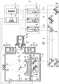
- FIG. 2 is a partial cross-sectional view showing a configuration of the EUV light generation system 11 applicable to the embodiment of the present disclosure.
- 3A to 3D show, as a first comparative example, the first prepulse laser beam P1, the second prepulse laser beam P2, and the main pulse when the irradiation diameter of the second prepulse laser beam P2 is smaller than the diameter of the secondary target.
- a state of the target 27 when the laser beam M is irradiated is schematically shown.
- FIG. 4A to 4D show, as a second comparative example, when the irradiation diameter of the second prepulse laser beam P2 is equal to the diameter of the secondary target, the first prepulse laser beam P1 and the second prepulse laser beam P2
- the state of the target 27 when the main pulse laser beam M is irradiated is schematically shown.
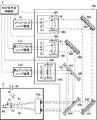
- FIG. 5 schematically illustrates a configuration example of the laser beam traveling direction control unit 34a and the periphery thereof in the EUV light generation system 11 according to the embodiment of the present disclosure.
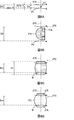
- 6A to 6D schematically show the state of the target 27 when the first prepulse laser beam P1, the second prepulse laser beam P2, and the main pulse laser beam M are irradiated in the embodiment of the present disclosure.
- FIG. 5 schematically illustrates a configuration example of the laser beam traveling direction control unit 34a and the periphery thereof in the EUV light generation system 11 according to the embodiment of the present disclosure.
- 6A to 6D schematically
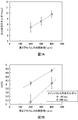
- FIG. 7A is a graph showing the relationship between the irradiation diameter of the second prepulse laser beam and the energy of the EUV light.
- FIG. 7B is a graph showing the relationship between the irradiation diameter of the second pre-pulse laser beam and the conversion efficiency (CE) from the laser beam energy to the EUV light energy.
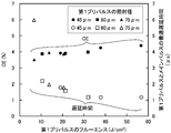
- FIG. 8 shows the relationship between the fluence of the first prepulse laser beam P1 and the conversion efficiency (CE) from the energy of the laser beam to the energy of the EUV light.
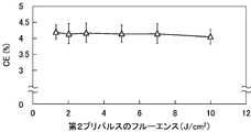
- FIG. 9 is a graph showing the relationship between the fluence of the second pre-pulse laser beam P2 and the conversion efficiency (CE) from the laser beam energy to the EUV light energy.
- FIG. 10 is a graph showing the relationship between the irradiation intensity of the main pulse laser beam M and the conversion efficiency (CE) from the laser beam energy to the EUV light energy.
- General description of extreme ultraviolet light generation system 1.1 Configuration 1.2 Operation EUV light generation system for irradiating a target with first to third laser beams 2.1 Configuration 2.1.1 Target supply unit 2.1.2 Target sensor and light emitting unit 2.1.3 Laser system 2.1.4 Laser beam traveling direction control unit 2.1.5 Condensing optical system 2.1.6 EUV collector mirror and EUV light sensor 2.2 Operation 2.2.1 Target output 2.2.2 Pulse laser beam output 2.2.3 Transmission of pulse laser beam 2.2.4 Condensing of pulse laser beam 2.3 Change of target irradiated with pulse laser beam 2.3.1 Radiation diameter of second pre-pulse laser beam P2 is 2 When smaller than the diameter of the secondary target 2.3.2 When the irradiation diameter of the second prepulse laser beam P2 is equal to the diameter of the secondary target 2.4 The irradiation diameter of the second prepulse laser beam P2 EUV light generation system larger than the irradiation diameter of the pulsed laser light M 2.4.1 Configuration 2.4.2 Change of the target irradiated
- FIG. 1 schematically shows a configuration of an exemplary LPP type EUV light generation system.
- the EUV light generation apparatus 1 may be used with at least one laser system 3.
- a system including the EUV light generation apparatus 1 and the laser system 3 is referred to as an EUV light generation system 11.
- the EUV light generation apparatus 1 may include a chamber 2 and a target supply unit 26.
- the chamber 2 may be sealable.
- the target supply unit 26 may be attached so as to penetrate the wall of the chamber 2, for example.
- the material of the target substance output from the target supply unit 26 may include, but is not limited to, tin, terbium, gadolinium, lithium, xenon, or a combination of any two or more thereof.
- the wall of the chamber 2 may be provided with at least one through hole.
- a window 21 may be provided in the through hole, and the pulse laser beam 32 output from the laser system 3 may pass through the window 21.
- an EUV collector mirror 23 having a spheroidal reflecting surface may be disposed.
- the EUV collector mirror 23 may have first and second focal points.
- On the surface of the EUV collector mirror 23, for example, a multilayer reflective film in which molybdenum and silicon are alternately laminated may be formed.
- the EUV collector mirror 23 is preferably arranged such that, for example, the first focal point thereof is located in the plasma generation region 25 and the second focal point thereof is located at the intermediate focal point (IF) 292.
- a through hole 24 may be provided at the center of the EUV collector mirror 23, and the pulse laser beam 33 may pass through the through hole 24.
- the EUV light generation apparatus 1 may include an EUV light generation control unit 5, a target sensor 4, and the like.
- the target sensor 4 may have an imaging function and may be configured to detect the presence, trajectory, position, speed, and the like of the target 27.
- the EUV light generation apparatus 1 may include a connection unit 29 that allows the inside of the chamber 2 and the inside of the exposure apparatus 6 to communicate with each other.
- a wall 291 in which an aperture is formed may be provided inside the connection portion 29.
- the wall 291 may be arranged such that its aperture is located at the second focal position of the EUV collector mirror 23.
- the EUV light generation apparatus 1 may include a laser beam traveling direction control unit 34, a laser beam focusing mirror 22, a target recovery unit 28 for recovering the target 27, and the like.
- the laser beam traveling direction control unit 34 may include an optical element for defining the traveling direction of the laser beam and an actuator for adjusting the position, posture, and the like of the optical element.
- the pulse laser beam 31 output from the laser system 3 passes through the window 21 as the pulse laser beam 32 through the laser beam traveling direction control unit 34 and enters the chamber 2. May be.
- the pulse laser beam 32 may travel through the chamber 2 along at least one laser beam path, be reflected by the laser beam collector mirror 22, and be irradiated to the at least one target 27 as the pulse laser beam 33.
- the target supply unit 26 may be configured to output the target 27 toward the plasma generation region 25 inside the chamber 2.
- the target 27 may be irradiated with at least one pulse included in the pulse laser beam 33.
- the target 27 irradiated with the pulsed laser light is turned into plasma, and radiation light 251 can be emitted from the plasma.
- the EUV collector mirror 23 may reflect the EUV light included in the emitted light 251 with a higher reflectance than light in other wavelength ranges.
- the reflected light 252 including the EUV light reflected by the EUV collector mirror 23 may be condensed at the intermediate condensing point 292 and output to the exposure apparatus 6.
- a single target 27 may be irradiated with a plurality of pulses included in the pulse laser beam 33.
- the EUV light generation controller 5 may be configured to control the entire EUV light generation system 11.
- the EUV light generation controller 5 may be configured to process image data of the target 27 imaged by the target sensor 4. Further, the EUV light generation control unit 5 may be configured to control the timing at which the target 27 is output, the output direction of the target 27, and the like, for example. Furthermore, the EUV light generation controller 5 may be configured to control, for example, the oscillation timing of the laser system 3, the traveling direction of the pulse laser light 32, the condensing position of the pulse laser light 33, and the like.
- the various controls described above are merely examples, and other controls may be added as necessary.
- FIG. 2 is a partial cross-sectional view showing a configuration of an EUV light generation system 11 applicable to the embodiment of the present disclosure.
- a condensing optical system 22 a, an EUV collector mirror 23, a target recovery unit 28, an EUV collector mirror holder 81, and plates 82 and 83 are provided inside the chamber 2. May be.
- a target supply unit 26, a target sensor 4, a light emitting unit 45, and an EUV light sensor 7 may be attached to the chamber 2.
- the EUV light generation control unit 5 may include an EUV control unit 50 and a delay circuit 51.
- the target supply unit 26 may include a reservoir 61.
- a part of the reservoir 61 may penetrate the through hole 2 a formed in the wall surface of the chamber 2, and the tip of the reservoir 61 may be located inside the chamber 2.
- An opening 62 may be formed at the tip of the reservoir 61.
- a vibration device (not shown) may be disposed near the opening 62 at the tip of the reservoir 61.
- the flange portion 61a of the reservoir 61 may be tightly fixed to the wall surface of the chamber 2 around the through hole 2a.
- the reservoir 61 may store the melted target material inside.
- the target material may be maintained at a temperature equal to or higher than its melting point by a heater (not shown) provided in the reservoir 61.
- the target material in the reservoir 61 may be pressurized by an inert gas supplied into the target supply unit 26.
- the target sensor 4 and the light emitting unit 45 may be arranged on opposite sides of the track of the target 27.
- Windows 21 a and 21 b may be attached to the chamber 2.
- the window 21 a may be located between the light emitting unit 45 and the trajectory of the target 27.
- the window 21 b may be located between the trajectory of the target 27 and the target sensor 4.
- the target sensor 4 may include an optical sensor 41, a condensing optical system 42, and a container 43.
- the container 43 may be fixed outside the chamber 2, and the optical sensor 41 and the condensing optical system 42 may be fixed in the container 43.
- the light emitting unit 45 may include a light source 46, a condensing optical system 47, and a container 48.
- the container 48 may be fixed outside the chamber 2, and the light source 46 and the condensing optical system 47 may be fixed in the container 48.
- the output light of the light source 46 can be condensed by the condensing optical system 47 at a position on the orbit of the target 27 between the target supply unit 26 and the plasma generation region 25.
- the target sensor 4 detects a change in the light intensity of the light passing through the trajectory of the target 27 and its surroundings, and outputs a target detection signal. Good.
- the laser system 3 may include a first prepulse laser apparatus La1, a second prepulse laser apparatus La2, and a main pulse laser apparatus Lb.
- Each of the first pre-pulse laser apparatus La1 and the second pre-pulse laser apparatus La2 may be a YAG laser apparatus.
- Each of the first prepulse laser apparatus La1 and the second prepulse laser apparatus La2 may be a laser apparatus using Nd: YVO 4 .
- the main pulse laser device Lb may be a CO 2 laser device.
- the YAG laser device may include a laser oscillator and, if necessary, a laser amplifier, and a YAG crystal may be used as a laser medium for either or both of the laser oscillator and the laser amplifier.
- the CO 2 laser device may include a laser oscillator and, if necessary, a laser amplifier, and one or both of the laser oscillator and the laser amplifier may use CO 2 gas as a laser medium.
- the first prepulse laser apparatus La1 may be configured to output the first prepulse laser beam P1.
- the first prepulse laser beam P1 may correspond to the first laser beam in the present disclosure.
- the second prepulse laser apparatus La2 may be configured to output the second prepulse laser beam P2.
- the second pre-pulse laser beam P2 can correspond to the second laser beam in the present disclosure.
- the main pulse laser device Lb may be configured to output the main pulse laser beam M.
- the main pulse laser beam M may correspond to the third laser beam in the present disclosure.
- the laser light travel direction control unit 34a may include high reflection mirrors 340, 341, and 342 and beam combiners 343 and 344.
- the high reflection mirror 340 may be supported by the holder 345.
- the high reflection mirror 341 may be supported by the holder 346.
- the high reflection mirror 342 may be supported by the holder 347.
- the beam combiner 343 may be supported by the holder 348.
- the beam combiner 343 transmits linearly polarized light whose polarization direction is parallel to the paper surface with a high transmittance, and reflects the linearly polarized light whose polarization direction is perpendicular to the paper surface with a high reflectance, so that the optical paths of the two lights are almost the same.
- a matching polarizer may be included.
- the beam combiner 344 may be supported by the holder 349.
- the beam combiner 344 transmits light including the first wavelength component with high transmittance, and reflects light including the second wavelength component with high reflectance, thereby substantially matching the optical paths of the two lights.
- a dichroic mirror may be included.
- the beam combiner 343 may also be a dichroic mirror.
- the plate 82 may be fixed to the chamber 2.
- a plate 83 may be supported on the plate 82.
- the condensing optical system 22a may include an off-axis paraboloid mirror 221 and a plane mirror 222.
- the off-axis parabolic mirror 221 may be supported by the holder 223.
- the plane mirror 222 may be supported by the holder 224.
- the holders 223 and 224 may be fixed to the plate 83.
- the position adjustment mechanism 84 may be capable of adjusting the position of the plate 83 relative to the plate 82 by a control signal output from the EUV control unit 50. By adjusting the position of the plate 83, the positions of the off-axis paraboloid mirror 221 and the plane mirror 222 may be adjusted. The positions of the off-axis paraboloid mirror 221 and the plane mirror 222 may be adjusted so that the pulsed laser light 33 reflected by these mirrors is collected in the plasma generation region 25.
- the EUV collector mirror 23 may be fixed to the plate 82 via the EUV collector mirror holder 81.
- the EUV light sensor 7 may receive a part of the EUV light generated in the plasma generation region 25 and detect the energy of the EUV light or the light intensity of the EUV light.
- the EUV light sensor 7 may output the detection result to the EUV control unit 50.
- the EUV control unit 50 included in the EUV light generation control unit 5 outputs a control signal to the target supply unit 26 so that the target supply unit 26 outputs the target 27. May be.
- the target material pressurized by the inert gas in the target supply unit 26 may be output through the opening 62.
- the target material may be separated into a plurality of droplets by applying vibration to the target supply unit 26 by the above-described vibration device. Each droplet may move in the direction of arrow Y along the trajectory from the target supply unit 26 to the plasma generation region 25 as the target 27.
- the target recovery unit 28 may be disposed on an extension of the trajectory of the target 27 and recover the target 27 that has passed through the plasma generation region 25.
- the EUV control unit 50 may receive a target detection signal output from the target sensor 4.
- the EUV control unit 50 may output a light emission trigger signal to the delay circuit 51 based on the target detection signal.
- the delay circuit 51 may output a first trigger signal indicating that the first delay time has elapsed with respect to the reception timing of the light emission trigger signal to the first prepulse laser apparatus La1.
- the first prepulse laser apparatus La1 may output the first prepulse laser light P1 in accordance with the first trigger signal.
- the delay circuit 51 outputs a second trigger signal indicating that a second delay time longer than the first delay time has elapsed with respect to the reception timing of the light emission trigger signal to the second prepulse laser apparatus La2. Also good.
- the second prepulse laser apparatus La2 may output the second prepulse laser beam P2 according to the second trigger signal.
- the delay circuit 51 outputs a third trigger signal indicating that a third delay time longer than the second delay time has elapsed with respect to the reception timing of the light emission trigger signal, to the main pulse laser device Lb.
- the main pulse laser device Lb may output the main pulse laser beam M in accordance with the third trigger signal.
- the difference between the first delay time and the third delay time may correspond to the delay time T1M from the irradiation timing of the first pre-pulse laser beam P1 to the irradiation timing of the main pulse laser beam M.
- the difference between the second delay time and the third delay time can correspond to the delay time T2M from the irradiation timing of the second pre-pulse laser beam P2 to the irradiation timing of the main pulse laser beam M.
- the delay time T1M and the delay time T2M will be described later.
- the laser system 3 may output the first pre-pulse laser beam P1, the second pre-pulse laser beam P2, and the main pulse laser beam M in this order.
- the first pre-pulse laser beam P1 preferably has a pulse time width on the order of picoseconds.
- the picosecond order may be 1 ps or more and less than 1 ns.
- the pulse time width of the second pre-pulse laser beam P2 is preferably shorter than the pulse time width of the main pulse laser beam M.
- the high reflection mirror 340 included in the laser beam traveling direction control unit 34a may be disposed in the optical path of the first prepulse laser beam P1 output by the first prepulse laser apparatus La1. .
- the high reflection mirror 340 may reflect the first pre-pulse laser beam P1 with a high reflectance.
- the beam combiner 343 is disposed at a position where the optical path of the first prepulse laser beam P1 reflected by the high reflection mirror 340 and the optical path of the second prepulse laser beam P2 output by the second prepulse laser apparatus La2 intersect. Also good.
- the first prepulse laser beam P1 may be linearly polarized light whose polarization direction is parallel to the paper surface.
- the second pre-pulse laser beam P2 may be linearly polarized light whose polarization direction is perpendicular to the paper surface.
- the first pre-pulse laser beam P1 may be incident on the beam combiner 343 from the upper side in the drawing.
- the second pre-pulse laser beam P2 may enter the beam combiner 343 from the left side in the drawing.
- the beam combiner 343 may transmit the first prepulse laser beam P1 with high transmittance, reflect the second prepulse laser beam P2 with high reflectivity, and guide the light to the beam combiner 344.
- the high reflection mirrors 341 and 342 may be disposed in the optical path of the main pulse laser beam M output by the main pulse laser device Lb.
- the high reflection mirrors 341 and 342 may sequentially reflect the main pulse laser beam M with a high reflectance.
- the beam combiner 344 may be disposed at a position where the optical paths of the first pre-pulse laser beam P1 and the second pre-pulse laser beam P2 intersect with the optical path of the main pulse laser beam M reflected by the high reflection mirror 342.
- the main pulse laser beam M may include a wavelength component different from the wavelength components included in the first prepulse laser beam P1 and the second prepulse laser beam P2.
- the first pre-pulse laser beam P1 and the second pre-pulse laser beam P2 may be incident on the beam combiner 344 from the upper side in the drawing.
- the main pulse laser beam M may enter the beam combiner 344 from the right side in the drawing.
- the beam combiner 344 reflects the first pre-pulse laser beam P1 and the second pre-pulse laser beam P2 with a high reflectance, transmits the main pulse laser beam M with a high transmittance, and condenses these lights as a pulse laser beam 32. You may guide to the optical system 22a.
- the off-axis parabolic mirror 221 included in the condensing optical system 22 a may be disposed in the optical path of the pulse laser light 32.
- the off-axis parabolic mirror 221 may reflect the pulse laser beam 32 toward the plane mirror 222.
- the plane mirror 222 may reflect the pulse laser beam 32 reflected by the off-axis paraboloid mirror 221 toward the plasma generation region 25 or the vicinity thereof as the pulse laser beam 33.
- the pulsed laser light 33 may be collected at or near the plasma generation region 25 according to the shape of the reflection surface of the off-axis paraboloidal mirror 221.
- one target 27 may be irradiated with the first pre-pulse laser beam P1, the second pre-pulse laser beam P2, and the main pulse laser beam M in this order.
- the droplet-shaped target 27 is irradiated with the first prepulse laser beam P1
- the droplet-shaped target 27 is broken into a plurality of fine particles and diffused, whereby a secondary target can be generated.
- a tertiary target including at least vapor or pre-plasma can be generated.
- the target can be efficiently converted into plasma and EUV light can be generated.
- the target may be irradiated with the fourth laser light between the first prepulse laser light P1 and the second prepulse laser light P2.
- the fifth laser beam may be irradiated on the target between the second pre-pulse laser beam P2 and the main pulse laser beam M.
- FIGS. 3A to 3D show the EUV light shown in FIG.
- the state of the target 27 when the first prepulse laser beam P1, the second prepulse laser beam P2, and the main pulse laser beam M are irradiated in the generation system is schematically shown.
- 3A to 3D show a case where the irradiation diameter D2 of the second prepulse laser beam P2 is smaller than the diameter of the secondary target 272 as a first comparative example.
- a broken line 270 indicates the trajectory of the target 27 and its extension line.
- the “irradiation diameter” refers to the diameter of the cross section of the optical path of the pulse laser beam at the irradiation position on the target.
- the irradiation diameter can correspond to the spot diameter.
- the diameter of the target 27 may be Dd.
- the variation in the position of the target 27 when the pre-pulse laser beam P1 is irradiated onto the target 27 may be ⁇ Dd.
- the positional variation ⁇ Dd of the target 27 may be the sum of the upward positional deviation amount ⁇ Dd / 2 in FIG. 3A and the downward positional deviation amount ⁇ Dd / 2 in FIG. 3A.
- the irradiation diameter D1 of the first prepulse laser beam P1 may be adjusted to Dd + ⁇ Dd.
- the droplet-shaped target 27 When the droplet-shaped target 27 is irradiated with the first pre-pulse laser beam P1, the droplet-shaped target 27 is broken into a plurality of fine particles and diffused to generate the secondary target 272 shown in FIG. 3B. Can be done.
- the density of the dots in FIGS. 3B-3D may correspond to the density of the target material.
- the secondary target 272 generated by irradiation with the first pre-pulse laser beam P1 having a pulse time width on the order of picoseconds may have an annular portion 27a and a dome portion 27b. .
- the annular portion 27a can be a region where the target material diffuses downstream of the optical path of the first pre-pulse laser beam P1 and the density of the target material is relatively high.
- the dome portion 27b can be a region where the target material is diffused upstream of the optical path of the first pre-pulse laser beam P1 and the density of the target material is relatively low.
- the upstream side of the optical path refers to the direction approaching the light source along the optical path, and the downstream side of the optical path refers to the direction away from the light source along the optical path.
- the secondary pre-pulse 272 may be irradiated with the second prepulse laser beam P2.
- the irradiation diameter D2 of the second prepulse laser beam P2 on the secondary target 272 may be smaller than the diameter of the secondary target 272.
- the secondary target 272 When the secondary pre-pulse laser beam P2 is irradiated to the secondary target 272, the secondary target 272 may be further broken down, evaporated, or pre-plasmaed to generate the tertiary target 273 shown in FIG. 3C. .
- the tertiary target 273 may include a dome portion 27d in which the dome portion 27b of the secondary target 272 is further finely broken, evaporated, or pre-plasmaized. Since the annular portion 27a of the secondary target 272 is irradiated with only the weak portion of the second pre-pulse laser beam P2 located on the outer peripheral portion or is hardly irradiated, most of the annular portion 27a is irradiated.
- the portion may be included in the tertiary target 273 as an annular portion 27c in which the density of the target material is relatively high.
- FIG. 3D shows the state of the tertiary target 273 in the latter half of the pulse time width of the main pulse laser beam M.
- the dome portion 27e containing plasma may have a lower density of the target material than the dome portion 27d.
- the annular portion 27c included in the tertiary target 273 may have a relatively high density of target material. If the density of the target material is higher than a certain threshold value, the target material is likely to reflect the main pulse laser beam M, and it may be difficult to absorb the energy of the main pulse laser beam M. For this reason, the generation of plasma from the annular portion 27c becomes insufficient, and the conversion efficiency from the energy of the laser light to the energy of the EUV light can be small.
- FIGS. 4A to 4D show the first prepulse laser beam P1 in the EUV light generation system shown in FIG.
- a state of the target 27 when the second pre-pulse laser beam P2 and the main pulse laser beam M are irradiated is schematically shown.
- 4A to 4D show a case where the irradiation diameter D2 of the second prepulse laser beam P2 is equal to the diameter of the secondary target 272 as a second comparative example.
- the relationship between the target 27 and the first prepulse laser beam P1 shown in FIG. 4A may be the same as that described with reference to FIG. 3A.
- the secondary target 272 shown in FIG. 4B may be similar to that described with reference to FIG. 3B.
- a broken line 270 indicates the trajectory of the target 27 and its extension line.
- the density of the dots in FIGS. 4B-4D may correspond to the density of the target material.
- the irradiation diameter D2 of the second pre-pulse laser beam P2 may be equal to the diameter of the secondary target 272.
- the tertiary target 273 generated by the irradiation with the second pre-pulse laser beam P2 may include a dome portion 27h in which the dome portion 27b of the secondary target 272 is further finely broken, evaporated, or pre-plasmaized. Since the second pre-pulse laser beam P2 is also applied to the annular portion 27a of the secondary target 272, the density of the target material can be reduced in a part of the annular portion 27a.
- the outer peripheral part of the annular part 27a is irradiated only with the weak part of the light located in the outer peripheral part of the second prepulse laser beam P2, the outer peripheral part of the annular part 27a is
- the tertiary target 273 may be included as an annular portion 27g having a relatively high target material density.
- FIG. 4D shows the state of the tertiary target 273 in the latter half of the pulse time width of the main pulse laser beam M.
- the conversion efficiency from the laser beam energy to the EUV light energy may decrease.
- the irradiation diameter D2 of the second pre-pulse laser beam P2 may be larger than the irradiation diameter Dm of the main pulse laser beam M. Therefore, the fall of the conversion efficiency from the energy of a laser beam to the energy of EUV light may be suppressed.
- FIG. 5 shows an EUV light generation system according to an embodiment of the present disclosure.
- 11 schematically shows a configuration example of the laser beam traveling direction control unit 34a in FIG.
- the configuration of the EUV collector mirror 23 and the target sensor 4 attached to the chamber 2 is not shown.
- the specific configurations of the condensing optical system 22a and the target supply unit 26 are also not shown.
- the laser beam traveling direction control unit 34 a may be an optical system that further includes a first beam expander 361, a second beam expander 362, and a third beam expander 363. .
- the first beam expander 361 is an optical path of the first prepulse laser beam P1, and may be disposed at a position different from the optical path of the second prepulse laser beam P2 and the optical path of the main pulse laser beam M.
- the second beam expander 362 is an optical path of the second prepulse laser light P2, and may be disposed at a position different from the optical path of the first prepulse laser light P1 and the optical path of the main pulse laser light M.
- the third beam expander 363 is an optical path of the main pulse laser beam M, and may be disposed at a position different from the optical path of the first prepulse laser beam P1 and the optical path of the second prepulse laser beam P2.
- the first beam expander 361, the second beam expander 362, and the third beam expander 363 may each include a spherical concave lens and a spherical convex lens.
- the third beam expander 363 may include a spherical convex mirror (not shown) and a spherical concave mirror (not shown) in order to withstand a large heat load.
- An actuator 365 may be attached to the spherical convex lens included in the first beam expander 361.
- An actuator 366 may be attached to the spherical convex lens included in the second beam expander 362.
- An actuator 367 may be attached to a spherical convex lens or a spherical concave mirror (not shown) included in the third beam expander 363.
- Actuators 365, 366, and 367 may be capable of moving the respective spherical convex lenses or spherical concave mirrors (not shown) along the optical path axes of the respective pulse laser beams. Accordingly, the first to third beam expanders 361 to 363 may adjust the wavefronts and beam diameters of the first pre-pulse laser beam P1, the second pre-pulse laser beam P2, and the main pulse laser beam M, respectively. By adjusting the wavefront and beam diameter, the irradiation diameter at the target may be adjusted.
- the first to third beam expanders 361 to 363 may correspond to adjustment mechanisms that adjust the irradiation diameters of the first pre-pulse laser beam P1, the second pre-pulse laser beam P2, and the main pulse laser beam M, respectively.
- the irradiation diameter D1 of the first pre-pulse laser beam P1 may be a size obtained by adding the position variation ⁇ Dd of the target 27 to the diameter Dd of the target 27.
- the irradiation diameter D2 of the second prepulse laser beam P2 may be larger than the diameter of the secondary target 272 generated by the irradiation of the first prepulse laser beam P1.
- the irradiation diameter Dm of the main pulse laser beam M may be smaller than the diameter of the tertiary target 273 generated by the irradiation of the second pre-pulse laser beam P2.
- the irradiation diameter D2 of the second pre-pulse laser beam P2 may be larger than the irradiation diameter Dm of the main pulse laser beam M.
- the condensing position of the second prepulse laser light P2 by the condensing optical system 22a is downstream of the optical path of the second prepulse laser light P2 relative to the position of the target 27. It may be located on the side.
- the second prepulse laser beam P2 incident on the condensing optical system 22a is a convex wave having a predetermined divergence angle. The wavefront of the prepulse laser beam P2 may be adjusted.
- the condensing position of the second prepulse laser light P2 by the condensing optical system 22a may be located upstream of the position of the target 27 in the optical path of the second prepulse laser light P2.
- the second prepulse laser beam P2 incident on the condensing optical system 22a may be adjusted to be a concave wave.
- the target 27 can move in the arrow Y direction from the irradiation timing of the first prepulse laser beam P1 to the target 27 until the irradiation timing of the second prepulse laser beam P2. Therefore, as shown in FIG. 5, the optical path axis of the first prepulse laser beam P ⁇ b> 1 may substantially intersect the trajectory of the target 27 at a position closer to the target supply unit 26 than the plasma generation region 25. Further, the optical path axis of the second pre-pulse laser beam P2 and the optical path axis of the main pulse laser beam M may pass through the plasma generation region 25.
- FIGS. 6A to 6D illustrate irradiation of the first prepulse laser beam P1, the second prepulse laser beam P2, and the main pulse laser beam M in the embodiment of the present disclosure.
- the state of the target 27 when being done is schematically shown.
- the relationship between the target 27 and the first prepulse laser beam P1 shown in FIG. 6A may be the same as that described with reference to FIG. 3A.
- the secondary target 272 shown in FIG. 6B may be the same as described with reference to FIG. 3B.
- a broken line 270 indicates the trajectory of the target 27 and its extension line.
- the density of the dots in FIGS. 6B-6D may correspond to the density of the target material.
- the irradiation diameter D2 of the second pre-pulse laser beam P2 is preferably larger than the diameter of the secondary target 272.
- the tertiary target 273 generated by the irradiation of the second pre-pulse laser beam P2 has a dome part 27b and an annular part 27a of the secondary target 272 broken down and evaporated more finely as shown in FIG. 6C.
- it may be a pre-plasmaized and fused mass.
- the tertiary target 273 may diffuse and expand over time.
- the main pulse laser beam M may be applied to the massive tertiary target 273.
- the irradiation diameter Dm of the main pulse laser beam M is smaller than the irradiation diameter D2 of the second pre-pulse laser beam P2.
- the main pulse laser beam M may be applied to the central portion of the tertiary target 273 excluding the outer peripheral portion.
- the tertiary target 273 may have a low density of the target material and can easily absorb the energy of the main pulse laser beam M. Thereby, the conversion efficiency from the energy of laser light to the energy of EUV light can be improved.
- the target material can efficiently absorb the energy of the main pulse laser beam M in the first half of the pulse time width of the main pulse laser beam M.
- the target material expands rapidly, and the density of the target material may decrease before the time of one pulse of the main pulse laser beam M ends. Therefore, in the second half of the pulse time width of the main pulse laser beam M, the density of the target material becomes too low, and the conversion efficiency from the laser beam energy to the EUV light energy may be reduced.
- the main pulse laser beam M may not be irradiated to the outer peripheral portion 27k outside the irradiation diameter of the main pulse laser beam M in the tertiary target 273. .
- the energy of the main pulse laser beam M is large, rapid expansion of the target material can be suppressed by the outer peripheral portion 27k.
- the target material can be supplied from the outer peripheral portion 27k within the irradiation diameter of the main pulse laser beam M.
- the decrease in the density of the target material within the irradiation diameter of the main pulse laser beam M can be alleviated.
- a decrease in conversion efficiency due to an increase in energy of the main pulse laser beam M can be mitigated.
- FIG. 7A is a graph showing the relationship between the irradiation diameter of the second pre-pulse laser beam P2 and the energy of the EUV light.
- a tin droplet having a diameter of 25 ⁇ m was used as the target 27.
- the first prepulse laser beam P1 had an irradiation diameter of 80 ⁇ m, a pulse time width of 14 ps, and a pulse energy of 0.77 mJ.
- the second prepulse laser beam P2 was measured with a pulse time width of 6 ns and a fluence of 10.0 J / cm 2 while changing the irradiation diameter D2.
- the main pulse laser beam M has an irradiation diameter of 325 ⁇ m, a pulse time width of 15 ns, and a pulse energy of 240 mJ.
- the EUV light energy was higher when the irradiation diameter D2 of the second pre-pulse laser beam P2 was 300 ⁇ m than when the irradiation diameter D2 was 200 ⁇ m. Further, the energy of the EUV light was higher when the irradiation diameter D2 of the second pre-pulse laser beam P2 was set to 400 ⁇ m, which was larger than the irradiation diameter of 325 ⁇ m of the main pulse laser beam M, compared to 300 ⁇ m.
- FIG. 7B is a graph showing the relationship between the irradiation diameter of the second pre-pulse laser beam P2 and the conversion efficiency (CE) from the laser beam energy to the EUV light energy.
- the measurement was performed both when the pulse energy of the main pulse laser beam M was 65 mJ and when it was 240 mJ.
- Other measurement conditions were the same as in FIG. 7A.
- the conversion efficiency from the laser beam energy to the EUV light energy is lowered when the pulse energy is increased to 240 mJ. That is, when the irradiation diameter D2 of the second pre-pulse laser beam P2 was 200 ⁇ m, the conversion efficiency was greatly reduced from about 4.1% to about 3.1%.
- the conversion efficiency decreases from about 4.7% to about 4.1%, and the irradiation diameter D2 of the second prepulse laser beam P2 The reduction in conversion efficiency was alleviated as compared with the case where the thickness was 200 ⁇ m.
- the diameter Dd of the target 27 may be in the following numerical range, which is typical in an LPP type EUV light generation apparatus. 1 ⁇ m ⁇ Dd ⁇ 100 ⁇ m
- the irradiation diameter D1 of the first pre-pulse laser beam P1 is preferably set so that the 5% width or 50% width is within a range obtained by adding the position variation ⁇ Dd of the target 27 to the diameter Dd of the target 27. Therefore, the irradiation diameter D1 of the first prepulse laser beam P1 may be larger than the diameter Dd of the target 27 as described below.
- 5% width means the diameter of the part which has 5% or more of peak intensity among the light intensity distribution in the irradiation position to a target.
- the 50% width means a diameter of a portion having a light intensity of 50% or more of the peak intensity in the light intensity distribution at the irradiation position on the target.
- the diameter Dd of the target 27 is 20 ⁇ m and the variation ⁇ Dd of the target 27 is 20 ⁇ m
- the range obtained by adding the variation DDd of the position of the target 27 to the diameter Dd of the target 27 is 40 ⁇ m.
- the light intensity distribution of the first prepulse laser beam P1 is a Gaussian distribution at the target irradiation position
- the irradiation diameter at which the 5% width is 40 ⁇ m is 68 ⁇ m at the 1 / e 2 width and the 50% width is 40 ⁇ m.
- the irradiation diameter can be 253 ⁇ m with a 1 / e 2 width.
- the irradiation diameter D1 of the first prepulse laser beam P1 may be in the following range. 50 ⁇ m ⁇ D1 ⁇ 300 ⁇ m
- the 1 / e 2 width means a diameter of a portion having a light intensity of 1 / e 2 or more of the peak intensity in the light intensity distribution at the irradiation position on the target.
- e is the number of Napier, and 1 / e 2 is about 13.5%.
- the irradiation diameter Dm of the main pulse laser beam M may be an irradiation diameter that realizes an irradiation intensity with high conversion efficiency from the energy of the laser beam to the energy of the EUV light.
- the irradiation intensity of the main pulse laser beam M is set to 5 ⁇ 10 9 W / cm 2 or more and 1 ⁇ 10 10 W / cm 2 or less from the energy of the laser beam. The result that it is preferable at the point of the conversion efficiency to the energy of is obtained.
- the irradiation intensity of the main pulse laser beam M will be described later with reference to FIG.
- the irradiation diameter Dm of the main pulse laser beam M may be in the following range. 450 ⁇ m ⁇ Dm ⁇ 900 ⁇ m
- the irradiation diameter Dm of the main pulse laser beam M may be smaller than the plasma diameter Dp.
- the irradiation diameter Dm of the main pulse laser beam M may be smaller than the diameter Dt of the tertiary target 273 when the main pulse laser beam M is irradiated.
- the plasma diameter Dp may be smaller than the diameter Dt of the tertiary target 273 when the main pulse laser beam M is irradiated.
- the irradiation diameter D2 of the second pre-pulse laser beam P2 may be equal to or greater than the diameter Dt of the tertiary target 273 when the main pulse laser beam M is irradiated.
- the upper limit of the irradiation diameter D2 of the second prepulse laser beam P2 can be determined by the distance between the targets 27.
- the upper limit of the irradiation diameter D2 of the second pre-pulse laser beam P2 may be 4000 ⁇ m.
- the irradiation diameter D2 of the second pre-pulse laser beam P2 is larger than the irradiation diameter Dm of the main pulse laser beam M. Therefore, the lower limit of the irradiation diameter D2 of the second prepulse laser beam P2 may be 300 ⁇ m.
- the irradiation diameter D2 of the second prepulse laser beam P2 may be in the following range. 300 ⁇ m ⁇ D2 ⁇ 4000 ⁇ m
- the irradiation diameter D2 of the second pre-pulse laser beam P2 may be in the following range. 300 ⁇ m ⁇ D2 ⁇ 900 ⁇ m
- the delay time T1M from the irradiation timing of the first pre-pulse laser beam P1 to the irradiation timing of the main pulse laser beam M is preferably in the following range. 0.5 ⁇ s ⁇ T1M ⁇ 3 ⁇ s
- the delay time T1M will be described later with reference to FIG.
- the delay time T2M from the irradiation timing of the second pre-pulse laser beam P2 to the irradiation timing of the main pulse laser beam M is preferably in the following range. 10ns ⁇ T2M ⁇ 300ns
- the delay time T2M is more preferably in the following range. 50ns ⁇ T2M ⁇ 100ns
- FIG. 8 shows EUV light energy from the fluence of the first prepulse laser light P1 and the laser light energy. It is a graph which shows the relationship with the conversion efficiency to (CE). FIG. 8 further shows the relationship between the fluence of the first prepulse laser beam P1 and the optimum value of the delay time T1M from the irradiation timing of the first prepulse laser beam P1 to the irradiation timing of the main pulse laser beam M.
- the first prepulse laser beam P1 has three values set as the irradiation diameter, and the pulse time width is 14 ps.
- the second prepulse laser beam P2 has a pulse time width of 12 ns and a pulse energy of 2 mJ, and a delay time T2M from the irradiation timing of the second prepulse laser beam P2 to the irradiation timing of the main pulse laser beam M is 120 ns.
- the main pulse laser beam M has an irradiation diameter of 300 ⁇ m, a pulse time width of 15 ns, and a pulse energy of 50 mJ.
- Measurement is performed at a plurality of delay times T1M with the irradiation diameter and fluence of the first prepulse laser beam P1 being constant, and the delay time T1M when the highest conversion efficiency is obtained is set as the optimum delay time, and the conversion efficiency at that time In addition, it is shown in FIG.
- the fluence of the first pre-pulse laser beam P1 may be 5 J / cm 2 or more and 60 J / cm 2 or less.
- the delay time T1M from the irradiation timing of the first pre-pulse laser beam P1 to the irradiation timing of the main pulse laser beam M is preferably in the following range. 0.5 ⁇ s ⁇ T1M ⁇ 3 ⁇ s
- FIG. 9 is a graph showing the relationship between the fluence of the second prepulse laser beam P2 and the conversion efficiency (CE) from the laser beam energy to the EUV light energy. It is.
- a tin droplet having a diameter of 25 ⁇ m was used as the target 27.
- the first prepulse laser beam P1 had an irradiation diameter of 80 ⁇ m, a pulse time width of 14 ps, and a pulse energy of 0.77 mJ.
- the second prepulse laser beam P2 was measured while changing the fluence with a pulse time width of 6 ns and an irradiation diameter of 400 ⁇ m.
- the main pulse laser beam M has an irradiation diameter of 404 ⁇ m, a pulse time width of 15 ns, and a pulse energy of 240 mJ.
- the fluence of the second pre-pulse laser beam P2 may be 1 J / cm 2 or more and 10 J / cm 2 or less.
- FIG. 10 is a graph showing the relationship between the main pulse laser light M irradiation intensity and the conversion efficiency (CE) from the laser light energy to the EUV light energy. It is.
- the irradiation intensity refers to the light intensity of the pulse laser beam at the irradiation position on the target. This light intensity may be an average value in a portion having a light intensity of 1 / e 2 or more of the peak intensity.
- the irradiation intensity of the main pulse laser beam M is preferably 5 ⁇ 10 9 W / cm 2 or more and 1 ⁇ 10 10 W / cm 2 or less.
Landscapes
- Physics & Mathematics (AREA)
- Optics & Photonics (AREA)
- Engineering & Computer Science (AREA)
- Plasma & Fusion (AREA)
- General Physics & Mathematics (AREA)
- Exposure And Positioning Against Photoresist Photosensitive Materials (AREA)
- X-Ray Techniques (AREA)
Abstract
極端紫外光生成装置は、所定領域に向けてターゲットを出力するターゲット供給部と、ターゲットに照射される第1レーザ光と、第1レーザ光が照射されたターゲットに照射される第2レーザ光と、第2レーザ光が照射されたターゲットに照射される第3レーザ光と、を出力するレーザシステムと、ターゲットにおける第2レーザ光の照射径が、ターゲットにおける第3レーザ光の照射径より大きくなるように構成された光学システムと、を備えてもよい。
Description
本開示は、極端紫外光生成装置に関する。
近年、半導体プロセスの微細化に伴って、半導体プロセスの光リソグラフィにおける転写パターンの微細化が急速に進展している。次世代においては、70nm~45nmの微細加工、さらには32nm以下の微細加工が要求されるようになる。このため、例えば32nm以下の微細加工の要求に応えるべく、波長13nm程度の極端紫外(EUV)光を生成する極端紫外光生成装置と縮小投影反射光学系(reduced projection reflection optics)とを組み合わせた露光装置の開発が期待されている。
EUV光生成装置としては、ターゲット物質にパルスレーザ光を照射することによって生成されるプラズマが用いられるLPP(Laser Produced Plasma)式の装置と、放電によって生成されるプラズマが用いられるDPP(Discharge Produced Plasma)式の装置と、シンクロトロン放射光が用いられるSR(Synchrotron Radiation)式の装置との3種類の装置が提案されている。
本開示の1つの観点に係る極端紫外光生成装置は、所定領域に向けてターゲットを出力するターゲット供給部と、ターゲットに照射される第1レーザ光と、第1レーザ光が照射されたターゲットに照射される第2レーザ光と、第2レーザ光が照射されたターゲットに照射される第3レーザ光と、を出力するレーザシステムと、ターゲットにおける第2レーザ光の照射径が、ターゲットにおける第3レーザ光の照射径より大きくなるように構成された光学システムと、を備えてもよい。
本開示のいくつかの実施形態を、単なる例として、添付の図面を参照して以下に説明する。
図1は、例示的なLPP式のEUV光生成システムの構成を概略的に示す。
図2は、本開示の実施形態に適用可能なEUV光生成システム11の構成を示す一部断面図である。
図3A~図3Dは、第1の比較例として、第2プリパルスレーザ光P2の照射径が2次ターゲットの直径より小さい場合に、第1プリパルスレーザ光P1、第2プリパルスレーザ光P2及びメインパルスレーザ光Mが照射されるときのターゲット27の様子を概略的に示す。
図4A~図4Dは、第2の比較例として、第2プリパルスレーザ光P2の照射径が、2次ターゲットの直径と同等である場合に、第1プリパルスレーザ光P1、第2プリパルスレーザ光P2及びメインパルスレーザ光Mが照射されるときのターゲット27の様子を概略的に示す。
図5は、本開示の実施形態に係るEUV光生成システム11におけるレーザ光進行方向制御部34a及びその周辺の構成例を概略的に示す。
図6A~図6Dは、本開示の実施形態において、第1プリパルスレーザ光P1、第2プリパルスレーザ光P2及びメインパルスレーザ光Mが照射されるときのターゲット27の様子を概略的に示す。
図7Aは、第2プリパルスレーザ光の照射径と、EUV光のエネルギーとの関係を示すグラフである。図7Bは、第2プリパルスレーザ光の照射径と、レーザ光のエネルギーからEUV光のエネルギーへの変換効率(CE)との関係を示すグラフである。
図8は、第1プリパルスレーザ光P1のフルーエンスと、レーザ光のエネルギーからEUV光のエネルギーへの変換効率(CE)との関係を示し、さらに、第1プリパルスレーザ光P1のフルーエンスと、第1プリパルスレーザ光P1の照射タイミングからメインパルスレーザ光Mの照射タイミングまでの遅延時間T1Mの最適値との関係も示す。
図9は、第2プリパルスレーザ光P2のフルーエンスと、レーザ光のエネルギーからEUV光のエネルギーへの変換効率(CE)との関係を示すグラフである。
図10は、メインパルスレーザ光Mの照射強度と、レーザ光のエネルギーからEUV光のエネルギーへの変換効率(CE)との関係を示すグラフである。
<内容>
1.極端紫外光生成システムの全体説明
1.1 構成
1.2 動作
2.第1~第3レーザ光をターゲットに照射するEUV光生成システム
2.1 構成
2.1.1 ターゲット供給部
2.1.2 ターゲットセンサ及び発光部
2.1.3 レーザシステム
2.1.4 レーザ光進行方向制御部
2.1.5 集光光学系
2.1.6 EUV集光ミラー及びEUV光センサ
2.2 動作
2.2.1 ターゲットの出力
2.2.2 パルスレーザ光の出力
2.2.3 パルスレーザ光の伝送
2.2.4 パルスレーザ光の集光
2.3 パルスレーザ光を照射されたターゲットの変化
2.3.1 第2プリパルスレーザ光P2の照射径が2次ターゲットの直径より小さい場合
2.3.2 第2プリパルスレーザ光P2の照射径が2次ターゲットの直径と同等である場合
2.4 第2プリパルスレーザ光P2の照射径を、メインパルスレーザ光Mの照射径より大きくしたEUV光生成システム
2.4.1 構成
2.4.2 パルスレーザ光を照射されたターゲットの変化
2.4.3 測定結果
2.4.4 照射径の数値範囲
2.4.4.1 液滴状のターゲットの直径Dd
2.4.4.2 第1プリパルスレーザ光の照射径D1
2.4.4.3 メインパルスレーザ光の照射径Dm
2.4.4.4 第2プリパルスレーザ光の照射径D2
2.4.5 遅延時間の範囲
2.4.6 パルスレーザ光のフルーエンス又は照射強度
2.4.6.1 第1プリパルスレーザ光のフルーエンス
2.4.6.2 第2プリパルスレーザ光のフルーエンス
2.4.6.3 メインパルスレーザ光の照射強度
3.補足
1.極端紫外光生成システムの全体説明
1.1 構成
1.2 動作
2.第1~第3レーザ光をターゲットに照射するEUV光生成システム
2.1 構成
2.1.1 ターゲット供給部
2.1.2 ターゲットセンサ及び発光部
2.1.3 レーザシステム
2.1.4 レーザ光進行方向制御部
2.1.5 集光光学系
2.1.6 EUV集光ミラー及びEUV光センサ
2.2 動作
2.2.1 ターゲットの出力
2.2.2 パルスレーザ光の出力
2.2.3 パルスレーザ光の伝送
2.2.4 パルスレーザ光の集光
2.3 パルスレーザ光を照射されたターゲットの変化
2.3.1 第2プリパルスレーザ光P2の照射径が2次ターゲットの直径より小さい場合
2.3.2 第2プリパルスレーザ光P2の照射径が2次ターゲットの直径と同等である場合
2.4 第2プリパルスレーザ光P2の照射径を、メインパルスレーザ光Mの照射径より大きくしたEUV光生成システム
2.4.1 構成
2.4.2 パルスレーザ光を照射されたターゲットの変化
2.4.3 測定結果
2.4.4 照射径の数値範囲
2.4.4.1 液滴状のターゲットの直径Dd
2.4.4.2 第1プリパルスレーザ光の照射径D1
2.4.4.3 メインパルスレーザ光の照射径Dm
2.4.4.4 第2プリパルスレーザ光の照射径D2
2.4.5 遅延時間の範囲
2.4.6 パルスレーザ光のフルーエンス又は照射強度
2.4.6.1 第1プリパルスレーザ光のフルーエンス
2.4.6.2 第2プリパルスレーザ光のフルーエンス
2.4.6.3 メインパルスレーザ光の照射強度
3.補足
以下、本開示の実施形態について、図面を参照しながら詳しく説明する。以下に説明される実施形態は、本開示のいくつかの例を示すものであって、本開示の内容を限定するものではない。また、各実施形態で説明される構成及び動作の全てが本開示の構成及び動作として必須であるとは限らない。なお、同一の構成要素には同一の参照符号を付して、重複する説明を省略する。
1.EUV光生成システムの全体説明
1.1 構成
図1に、例示的なLPP式のEUV光生成システムの構成を概略的に示す。EUV光生成装置1は、少なくとも1つのレーザシステム3と共に用いられてもよい。本願においては、EUV光生成装置1及びレーザシステム3を含むシステムを、EUV光生成システム11と称する。図1に示し、かつ、以下に詳細に説明するように、EUV光生成装置1は、チャンバ2、ターゲット供給部26を含んでもよい。チャンバ2は、密閉可能であってもよい。ターゲット供給部26は、例えば、チャンバ2の壁を貫通するように取り付けられてもよい。ターゲット供給部26から出力されるターゲット物質の材料は、スズ、テルビウム、ガドリニウム、リチウム、キセノン、又は、それらの内のいずれか2つ以上の組合せを含んでもよいが、これらに限定されない。
1.1 構成
図1に、例示的なLPP式のEUV光生成システムの構成を概略的に示す。EUV光生成装置1は、少なくとも1つのレーザシステム3と共に用いられてもよい。本願においては、EUV光生成装置1及びレーザシステム3を含むシステムを、EUV光生成システム11と称する。図1に示し、かつ、以下に詳細に説明するように、EUV光生成装置1は、チャンバ2、ターゲット供給部26を含んでもよい。チャンバ2は、密閉可能であってもよい。ターゲット供給部26は、例えば、チャンバ2の壁を貫通するように取り付けられてもよい。ターゲット供給部26から出力されるターゲット物質の材料は、スズ、テルビウム、ガドリニウム、リチウム、キセノン、又は、それらの内のいずれか2つ以上の組合せを含んでもよいが、これらに限定されない。
チャンバ2の壁には、少なくとも1つの貫通孔が設けられていてもよい。その貫通孔には、ウインドウ21が設けられてもよく、ウインドウ21をレーザシステム3から出力されるパルスレーザ光32が透過してもよい。チャンバ2の内部には、例えば、回転楕円面形状の反射面を有するEUV集光ミラー23が配置されてもよい。EUV集光ミラー23は、第1及び第2の焦点を有し得る。EUV集光ミラー23の表面には、例えば、モリブデンとシリコンとが交互に積層された多層反射膜が形成されていてもよい。EUV集光ミラー23は、例えば、その第1の焦点がプラズマ生成領域25に位置し、その第2の焦点が中間集光点(IF)292に位置するように配置されるのが好ましい。EUV集光ミラー23の中央部には貫通孔24が設けられていてもよく、貫通孔24をパルスレーザ光33が通過してもよい。
EUV光生成装置1は、EUV光生成制御部5、ターゲットセンサ4等を含んでもよい。ターゲットセンサ4は、撮像機能を有してもよく、ターゲット27の存在、軌跡、位置、速度等を検出するよう構成されてもよい。
また、EUV光生成装置1は、チャンバ2の内部と露光装置6の内部とを連通させる接続部29を含んでもよい。接続部29内部には、アパーチャが形成された壁291が設けられてもよい。壁291は、そのアパーチャがEUV集光ミラー23の第2の焦点位置に位置するように配置されてもよい。
さらに、EUV光生成装置1は、レーザ光進行方向制御部34、レーザ光集光ミラー22、ターゲット27を回収するためのターゲット回収部28等を含んでもよい。レーザ光進行方向制御部34は、レーザ光の進行方向を規定するための光学素子と、この光学素子の位置、姿勢等を調整するためのアクチュエータとを備えてもよい。
1.2 動作
図1を参照に、レーザシステム3から出力されたパルスレーザ光31は、レーザ光進行方向制御部34を経て、パルスレーザ光32としてウインドウ21を透過してチャンバ2内に入射してもよい。パルスレーザ光32は、少なくとも1つのレーザ光経路に沿ってチャンバ2内を進み、レーザ光集光ミラー22で反射されて、パルスレーザ光33として少なくとも1つのターゲット27に照射されてもよい。
図1を参照に、レーザシステム3から出力されたパルスレーザ光31は、レーザ光進行方向制御部34を経て、パルスレーザ光32としてウインドウ21を透過してチャンバ2内に入射してもよい。パルスレーザ光32は、少なくとも1つのレーザ光経路に沿ってチャンバ2内を進み、レーザ光集光ミラー22で反射されて、パルスレーザ光33として少なくとも1つのターゲット27に照射されてもよい。
ターゲット供給部26は、ターゲット27をチャンバ2内部のプラズマ生成領域25に向けて出力するよう構成されてもよい。ターゲット27には、パルスレーザ光33に含まれる少なくとも1つのパルスが照射されてもよい。パルスレーザ光が照射されたターゲット27はプラズマ化し、そのプラズマから放射光251が放射され得る。EUV集光ミラー23は、放射光251に含まれるEUV光を、他の波長域の光に比べて高い反射率で反射してもよい。EUV集光ミラー23によって反射されたEUV光を含む反射光252は、中間集光点292で集光され、露光装置6に出力されてもよい。なお、1つのターゲット27に、パルスレーザ光33に含まれる複数のパルスが照射されてもよい。
EUV光生成制御部5は、EUV光生成システム11全体の制御を統括するよう構成されてもよい。EUV光生成制御部5は、ターゲットセンサ4によって撮像されたターゲット27のイメージデータ等を処理するよう構成されてもよい。また、EUV光生成制御部5は、例えば、ターゲット27が出力されるタイミング、ターゲット27の出力方向等を制御するよう構成されてもよい。さらに、EUV光生成制御部5は、例えば、レーザシステム3の発振タイミング、パルスレーザ光32の進行方向、パルスレーザ光33の集光位置等を制御するよう構成されてもよい。上述の様々な制御は単なる例示に過ぎず、必要に応じて他の制御が追加されてもよい。
2.第1~第3レーザ光をターゲットに照射するEUV光生成システム
2.1 構成
図2は、本開示の実施形態に適用可能なEUV光生成システム11の構成を示す一部断面図である。図2に示されるように、チャンバ2の内部には、集光光学系22aと、EUV集光ミラー23と、ターゲット回収部28と、EUV集光ミラーホルダ81と、プレート82及び83とが設けられてもよい。チャンバ2には、ターゲット供給部26と、ターゲットセンサ4と、発光部45と、EUV光センサ7とが取り付けられてもよい。
2.1 構成
図2は、本開示の実施形態に適用可能なEUV光生成システム11の構成を示す一部断面図である。図2に示されるように、チャンバ2の内部には、集光光学系22aと、EUV集光ミラー23と、ターゲット回収部28と、EUV集光ミラーホルダ81と、プレート82及び83とが設けられてもよい。チャンバ2には、ターゲット供給部26と、ターゲットセンサ4と、発光部45と、EUV光センサ7とが取り付けられてもよい。
チャンバ2の外部には、レーザシステム3と、レーザ光進行方向制御部34aと、EUV光生成制御部5とが設けられてもよい。EUV光生成制御部5は、EUV制御部50と、遅延回路51とを含んでいても良い。
2.1.1 ターゲット供給部
ターゲット供給部26は、リザーバ61を有していても良い。リザーバ61の一部が、チャンバ2の壁面に形成された貫通孔2aを貫通しており、リザーバ61の先端がチャンバ2の内部に位置していてもよい。リザーバ61の上記先端には、開口62が形成されていてもよい。リザーバ61の上記先端の開口62付近に、図示しない加振装置が配置されてもよい。貫通孔2aの周囲のチャンバ2の壁面には、リザーバ61のフランジ部61aが密着して固定されてもよい。
ターゲット供給部26は、リザーバ61を有していても良い。リザーバ61の一部が、チャンバ2の壁面に形成された貫通孔2aを貫通しており、リザーバ61の先端がチャンバ2の内部に位置していてもよい。リザーバ61の上記先端には、開口62が形成されていてもよい。リザーバ61の上記先端の開口62付近に、図示しない加振装置が配置されてもよい。貫通孔2aの周囲のチャンバ2の壁面には、リザーバ61のフランジ部61aが密着して固定されてもよい。
リザーバ61は、溶融されたターゲットの材料を、内部に貯蔵してもよい。リザーバ61に備えられた図示しないヒータによって、ターゲットの材料がその融点以上の温度に維持されてもよい。リザーバ61内のターゲットの材料は、ターゲット供給部26の内部に供給される不活性ガスによって加圧されてもよい。
2.1.2 ターゲットセンサ及び発光部
ターゲットセンサ4と発光部45とは、ターゲット27の軌道を挟んで互いに反対側に配置されていてもよい。チャンバ2にはウインドウ21a及び21bが取り付けられていてもよい。ウインドウ21aは、発光部45とターゲット27の軌道との間に位置していてもよい。ウインドウ21bは、ターゲット27の軌道とターゲットセンサ4との間に位置していてもよい。
ターゲットセンサ4と発光部45とは、ターゲット27の軌道を挟んで互いに反対側に配置されていてもよい。チャンバ2にはウインドウ21a及び21bが取り付けられていてもよい。ウインドウ21aは、発光部45とターゲット27の軌道との間に位置していてもよい。ウインドウ21bは、ターゲット27の軌道とターゲットセンサ4との間に位置していてもよい。
ターゲットセンサ4は、光センサ41と、集光光学系42と、容器43とを含んでもよい。容器43はチャンバ2の外部に固定され、この容器43内に、光センサ41及び集光光学系42が固定されてもよい。発光部45は、光源46と、集光光学系47と、容器48とを含んでもよい。容器48はチャンバ2の外部に固定され、この容器48内に、光源46及び集光光学系47が固定されてもよい。
光源46の出力光は、集光光学系47によって、ターゲット供給部26とプラズマ生成領域25との間のターゲット27のほぼ軌道上の位置に、集光され得る。ターゲット27が発光部45による光の集光位置を通過するときに、ターゲットセンサ4は、ターゲット27の軌道及びその周囲を通る光の光強度の変化を検出し、ターゲット検出信号を出力してもよい。
2.1.3 レーザシステム
レーザシステム3は、第1プリパルスレーザ装置La1と、第2プリパルスレーザ装置La2と、メインパルスレーザ装置Lbとを含んでいてもよい。第1プリパルスレーザ装置La1及び第2プリパルスレーザ装置La2の各々は、YAGレーザ装置であってもよい。第1プリパルスレーザ装置La1及び第2プリパルスレーザ装置La2の各々は、Nd:YVO4を用いたレーザ装置であってもよい。メインパルスレーザ装置Lbは、CO2レーザ装置であってもよい。なお、YAGレーザ装置とは、レーザ発振器及び必要に応じてレーザ増幅器を含み、レーザ発振器及びレーザ増幅器のいずれか又は両方に、レーザ媒質としてYAG結晶を用いるものでもよい。CO2レーザ装置とは、レーザ発振器及び必要に応じてレーザ増幅器を含み、レーザ発振器及びレーザ増幅器のいずれか又は両方に、レーザ媒質としてCO2ガスを用いるものでもよい。
レーザシステム3は、第1プリパルスレーザ装置La1と、第2プリパルスレーザ装置La2と、メインパルスレーザ装置Lbとを含んでいてもよい。第1プリパルスレーザ装置La1及び第2プリパルスレーザ装置La2の各々は、YAGレーザ装置であってもよい。第1プリパルスレーザ装置La1及び第2プリパルスレーザ装置La2の各々は、Nd:YVO4を用いたレーザ装置であってもよい。メインパルスレーザ装置Lbは、CO2レーザ装置であってもよい。なお、YAGレーザ装置とは、レーザ発振器及び必要に応じてレーザ増幅器を含み、レーザ発振器及びレーザ増幅器のいずれか又は両方に、レーザ媒質としてYAG結晶を用いるものでもよい。CO2レーザ装置とは、レーザ発振器及び必要に応じてレーザ増幅器を含み、レーザ発振器及びレーザ増幅器のいずれか又は両方に、レーザ媒質としてCO2ガスを用いるものでもよい。
第1プリパルスレーザ装置La1は、第1プリパルスレーザ光P1を出力するように構成されてもよい。第1プリパルスレーザ光P1は、本開示における第1レーザ光に相当し得る。第2プリパルスレーザ装置La2は、第2プリパルスレーザ光P2を出力するように構成されてもよい。第2プリパルスレーザ光P2は、本開示における第2レーザ光に相当し得る。メインパルスレーザ装置Lbは、メインパルスレーザ光Mを出力するように構成されてもよい。メインパルスレーザ光Mは、本開示における第3レーザ光に相当し得る。
2.1.4 レーザ光進行方向制御部
レーザ光進行方向制御部34aは、高反射ミラー340、341及び342と、ビームコンバイナ343及び344と、を含んでもよい。高反射ミラー340は、ホルダ345によって支持されていてもよい。高反射ミラー341は、ホルダ346によって支持されていてもよい。高反射ミラー342は、ホルダ347によって支持されていてもよい。
レーザ光進行方向制御部34aは、高反射ミラー340、341及び342と、ビームコンバイナ343及び344と、を含んでもよい。高反射ミラー340は、ホルダ345によって支持されていてもよい。高反射ミラー341は、ホルダ346によって支持されていてもよい。高反射ミラー342は、ホルダ347によって支持されていてもよい。
ビームコンバイナ343は、ホルダ348によって支持されていてもよい。ビームコンバイナ343は、偏光方向が紙面に平行な直線偏光を、高い透過率で透過させ、偏光方向が紙面に垂直な直線偏光を、高い反射率で反射することにより、2つの光の光路をほぼ一致させる偏光子を含んでもよい。
ビームコンバイナ344は、ホルダ349によって支持されていてもよい。ビームコンバイナ344は、第1の波長成分が含まれる光を高い透過率で透過させ、第2の波長成分が含まれる光を高い反射率で反射することにより、2つの光の光路をほぼ一致させるダイクロイックミラーを含んでもよい。
なお、第1プリパルスレーザ光P1と第2プリパルスレーザ光P2とが異なる波長成分を有する場合には、ビームコンバイナ343も、ダイクロイックミラーであってよい。
なお、第1プリパルスレーザ光P1と第2プリパルスレーザ光P2とが異なる波長成分を有する場合には、ビームコンバイナ343も、ダイクロイックミラーであってよい。
2.1.5 集光光学系
プレート82は、チャンバ2に固定されてもよい。プレート82には、プレート83が支持されてもよい。集光光学系22aは、軸外放物面ミラー221及び平面ミラー222を含んでもよい。軸外放物面ミラー221は、ホルダ223によって支持されてもよい。平面ミラー222は、ホルダ224によって支持されてもよい。ホルダ223及び224は、プレート83に固定されてもよい。
プレート82は、チャンバ2に固定されてもよい。プレート82には、プレート83が支持されてもよい。集光光学系22aは、軸外放物面ミラー221及び平面ミラー222を含んでもよい。軸外放物面ミラー221は、ホルダ223によって支持されてもよい。平面ミラー222は、ホルダ224によって支持されてもよい。ホルダ223及び224は、プレート83に固定されてもよい。
位置調整機構84は、EUV制御部50から出力される制御信号により、プレート82に対するプレート83の位置を調整可能であってもよい。プレート83の位置が調整されることにより、軸外放物面ミラー221及び平面ミラー222の位置が調整されてもよい。軸外放物面ミラー221及び平面ミラー222の位置は、これらのミラーによって反射されたパルスレーザ光33がプラズマ生成領域25で集光するように調整されてもよい。
2.1.6 EUV集光ミラー及びEUV光センサ
EUV集光ミラー23は、EUV集光ミラーホルダ81を介してプレート82に固定されていてもよい。EUV光センサ7は、プラズマ生成領域25において発生したEUV光の一部を受光し、EUV光のエネルギー又はEUV光の光強度を検出してもよい。EUV光センサ7は、検出結果をEUV制御部50へ出力してもよい。
EUV集光ミラー23は、EUV集光ミラーホルダ81を介してプレート82に固定されていてもよい。EUV光センサ7は、プラズマ生成領域25において発生したEUV光の一部を受光し、EUV光のエネルギー又はEUV光の光強度を検出してもよい。EUV光センサ7は、検出結果をEUV制御部50へ出力してもよい。
2.2 動作
2.2.1 ターゲットの出力
EUV光生成制御部5に含まれるEUV制御部50は、ターゲット供給部26がターゲット27を出力するように、ターゲット供給部26に制御信号を出力してもよい。
ターゲット供給部26において、不活性ガスによって加圧されたターゲットの材料は、開口62を介して出力されてもよい。上述の加振装置によってターゲット供給部26に振動が与えられることにより、ターゲットの材料は複数のドロップレットに分離されてもよい。それぞれのドロップレットが、ターゲット27として、ターゲット供給部26からプラズマ生成領域25までの軌道に沿って矢印Y方向に移動してもよい。
2.2.1 ターゲットの出力
EUV光生成制御部5に含まれるEUV制御部50は、ターゲット供給部26がターゲット27を出力するように、ターゲット供給部26に制御信号を出力してもよい。
ターゲット供給部26において、不活性ガスによって加圧されたターゲットの材料は、開口62を介して出力されてもよい。上述の加振装置によってターゲット供給部26に振動が与えられることにより、ターゲットの材料は複数のドロップレットに分離されてもよい。それぞれのドロップレットが、ターゲット27として、ターゲット供給部26からプラズマ生成領域25までの軌道に沿って矢印Y方向に移動してもよい。
ターゲット回収部28は、ターゲット27の軌道の延長線上に配置され、プラズマ生成領域25を通過したターゲット27を回収してもよい。
EUV制御部50は、ターゲットセンサ4から出力されるターゲット検出信号を受信してもよい。
EUV制御部50は、ターゲットセンサ4から出力されるターゲット検出信号を受信してもよい。
2.2.2 パルスレーザ光の出力
EUV制御部50は、ターゲット検出信号に基づいて、発光トリガ信号を遅延回路51に出力してもよい。遅延回路51は、発光トリガ信号の受信タイミングに対して第1の遅延時間が経過したことを示す第1のトリガ信号を、第1プリパルスレーザ装置La1に出力してもよい。第1プリパルスレーザ装置La1は、第1のトリガ信号に従って、第1プリパルスレーザ光P1を出力してもよい。
EUV制御部50は、ターゲット検出信号に基づいて、発光トリガ信号を遅延回路51に出力してもよい。遅延回路51は、発光トリガ信号の受信タイミングに対して第1の遅延時間が経過したことを示す第1のトリガ信号を、第1プリパルスレーザ装置La1に出力してもよい。第1プリパルスレーザ装置La1は、第1のトリガ信号に従って、第1プリパルスレーザ光P1を出力してもよい。
遅延回路51は、発光トリガ信号の受信タイミングに対して、第1の遅延時間より長い第2の遅延時間が経過したことを示す第2のトリガ信号を、第2プリパルスレーザ装置La2に出力してもよい。第2プリパルスレーザ装置La2は、第2のトリガ信号に従って、第2プリパルスレーザ光P2を出力してもよい。
遅延回路51は、発光トリガ信号の受信タイミングに対して、第2の遅延時間より長い第3の遅延時間が経過したことを示す第3のトリガ信号を、メインパルスレーザ装置Lbに出力してもよい。メインパルスレーザ装置Lbは、第3のトリガ信号に従って、メインパルスレーザ光Mを出力してもよい。
第1の遅延時間と第3の遅延時間との差が、第1プリパルスレーザ光P1の照射タイミングからメインパルスレーザ光Mの照射タイミングまでの遅延時間T1Mに相当し得る。第2の遅延時間と第3の遅延時間との差が、第2プリパルスレーザ光P2の照射タイミングからメインパルスレーザ光Mの照射タイミングまでの遅延時間T2Mに相当し得る。遅延時間T1M及び遅延時間T2Mについては後述する。
第1の遅延時間と第3の遅延時間との差が、第1プリパルスレーザ光P1の照射タイミングからメインパルスレーザ光Mの照射タイミングまでの遅延時間T1Mに相当し得る。第2の遅延時間と第3の遅延時間との差が、第2プリパルスレーザ光P2の照射タイミングからメインパルスレーザ光Mの照射タイミングまでの遅延時間T2Mに相当し得る。遅延時間T1M及び遅延時間T2Mについては後述する。
このように、レーザシステム3は、第1プリパルスレーザ光P1、第2プリパルスレーザ光P2、メインパルスレーザ光Mを、この順で出力してもよい。第1プリパルスレーザ光P1は、ピコ秒オーダーのパルス時間幅を有することが好ましい。ピコ秒オーダーとは、1ps以上、1ns未満であってもよい。第2プリパルスレーザ光P2のパルス時間幅は、メインパルスレーザ光Mのパルス時間幅より短いことが好ましい。
2.2.3 パルスレーザ光の伝送
レーザ光進行方向制御部34aに含まれる高反射ミラー340は、第1プリパルスレーザ装置La1によって出力された第1プリパルスレーザ光P1の光路に配置されてもよい。高反射ミラー340は、第1プリパルスレーザ光P1を高い反射率で反射してもよい。
レーザ光進行方向制御部34aに含まれる高反射ミラー340は、第1プリパルスレーザ装置La1によって出力された第1プリパルスレーザ光P1の光路に配置されてもよい。高反射ミラー340は、第1プリパルスレーザ光P1を高い反射率で反射してもよい。
ビームコンバイナ343は、高反射ミラー340によって反射された第1プリパルスレーザ光P1の光路と、第2プリパルスレーザ装置La2によって出力された第2プリパルスレーザ光P2の光路とが交差する位置に配置されてもよい。第1プリパルスレーザ光P1は、偏光方向が紙面に平行な直線偏光であってもよい。第2プリパルスレーザ光P2は、偏光方向が紙面に垂直な直線偏光であってもよい。
第1プリパルスレーザ光P1は、ビームコンバイナ343に図中上側から入射してもよい。第2プリパルスレーザ光P2は、ビームコンバイナ343に図中左側から入射してもよい。ビームコンバイナ343は、第1プリパルスレーザ光P1を高い透過率で透過させ、第2プリパルスレーザ光P2を高い反射率で反射し、これらの光をビームコンバイナ344に導いてもよい。
高反射ミラー341及び342は、メインパルスレーザ装置Lbによって出力されたメインパルスレーザ光Mの光路に配置されてもよい。高反射ミラー341及び342は、メインパルスレーザ光Mを高い反射率で順次反射してもよい。
ビームコンバイナ344は、第1プリパルスレーザ光P1及び第2プリパルスレーザ光P2の光路と、高反射ミラー342によって反射されたメインパルスレーザ光Mの光路とが交差する位置に配置されてもよい。メインパルスレーザ光Mは、第1プリパルスレーザ光P1及び第2プリパルスレーザ光P2に含まれる波長成分と異なる波長成分を含んでもよい。
第1プリパルスレーザ光P1及び第2プリパルスレーザ光P2は、ビームコンバイナ344に図中上側から入射してもよい。メインパルスレーザ光Mは、ビームコンバイナ344に図中右側から入射してもよい。ビームコンバイナ344は、第1プリパルスレーザ光P1及び第2プリパルスレーザ光P2を高い反射率で反射し、メインパルスレーザ光Mを高い透過率で透過させ、これらの光をパルスレーザ光32として集光光学系22aに導いてもよい。
2.2.4 パルスレーザ光の集光
集光光学系22aに含まれる軸外放物面ミラー221は、パルスレーザ光32の光路に配置されてもよい。軸外放物面ミラー221は、パルスレーザ光32を平面ミラー222に向けて反射してもよい。平面ミラー222は、軸外放物面ミラー221によって反射されたパルスレーザ光32を、パルスレーザ光33としてプラズマ生成領域25又はその近傍に向けて反射してもよい。パルスレーザ光33は、軸外放物面ミラー221の反射面形状に従い、プラズマ生成領域25又はその近傍において集光されてもよい。
集光光学系22aに含まれる軸外放物面ミラー221は、パルスレーザ光32の光路に配置されてもよい。軸外放物面ミラー221は、パルスレーザ光32を平面ミラー222に向けて反射してもよい。平面ミラー222は、軸外放物面ミラー221によって反射されたパルスレーザ光32を、パルスレーザ光33としてプラズマ生成領域25又はその近傍に向けて反射してもよい。パルスレーザ光33は、軸外放物面ミラー221の反射面形状に従い、プラズマ生成領域25又はその近傍において集光されてもよい。
プラズマ生成領域25又はその近傍において、1つのターゲット27に、第1プリパルスレーザ光P1と、第2プリパルスレーザ光P2と、メインパルスレーザ光Mとが、この順で照射されてもよい。液滴状のターゲット27に第1プリパルスレーザ光P1が照射されると、液滴状のターゲット27が複数の微粒子状に破壊されて拡散することにより、2次ターゲットが生成され得る。この2次ターゲットに第2プリパルスレーザ光P2が照射されることにより、蒸気又はプリプラズマを少なくとも含む3次ターゲットが生成され得る。この3次ターゲットにメインパルスレーザ光Mが照射されることにより、ターゲットが効率よくプラズマ化し、EUV光が生成され得る。なお、本開示はこれに限らず、第1プリパルスレーザ光P1と第2プリパルスレーザ光P2との間に、第4レーザ光がターゲットに照射されてもよい。第2プリパルスレーザ光P2とメインパルスレーザ光Mとの間に、第5レーザ光がターゲットに照射されてもよい。
2.3 パルスレーザ光を照射されたターゲットの変化
2.3.1 第2プリパルスレーザ光P2の照射径が2次ターゲットの直径より小さい場合
図3A~図3Dは、図2に示されるEUV光生成システムにおいて第1プリパルスレーザ光P1、第2プリパルスレーザ光P2及びメインパルスレーザ光Mが照射されるときのターゲット27の様子を概略的に示す。図3A~図3Dは、第1の比較例として、第2プリパルスレーザ光P2の照射径D2が2次ターゲット272の直径より小さい場合を示す。破線270は、ターゲット27の軌道及びその延長線を示す。
なお、本開示において「照射径」とは、ターゲットへの照射位置におけるパルスレーザ光の光路断面の直径をいう。集光光学系22aによってパルスレーザ光が集光される位置にターゲットが位置する場合には、照射径はスポット径に相当し得る。
2.3.1 第2プリパルスレーザ光P2の照射径が2次ターゲットの直径より小さい場合
図3A~図3Dは、図2に示されるEUV光生成システムにおいて第1プリパルスレーザ光P1、第2プリパルスレーザ光P2及びメインパルスレーザ光Mが照射されるときのターゲット27の様子を概略的に示す。図3A~図3Dは、第1の比較例として、第2プリパルスレーザ光P2の照射径D2が2次ターゲット272の直径より小さい場合を示す。破線270は、ターゲット27の軌道及びその延長線を示す。
なお、本開示において「照射径」とは、ターゲットへの照射位置におけるパルスレーザ光の光路断面の直径をいう。集光光学系22aによってパルスレーザ光が集光される位置にターゲットが位置する場合には、照射径はスポット径に相当し得る。
図3Aに示されるように、ターゲット27の直径をDdとしてもよい。プリパルスレーザ光P1がターゲット27に照射されるときのターゲット27の位置のばらつきをΔDdとしてもよい。ターゲット27の位置のばらつきΔDdは、図3Aにおける上方向への位置ずれ量ΔDd/2と、図3Aにおける下方向への位置ずれ量ΔDd/2との合計であってもよい。第1プリパルスレーザ光P1の照射径D1は、Dd+ΔDdに調整されてもよい。
液滴状のターゲット27に第1プリパルスレーザ光P1が照射されると、液滴状のターゲット27が複数の微粒子状に破壊されて拡散することにより、図3Bに示される2次ターゲット272が生成され得る。図3B~図3Dにおけるドットの粗密は、ターゲット物質の密度に対応し得る。図3Bに示されるように、ピコ秒オーダーのパルス時間幅を有する第1プリパルスレーザ光P1が照射されて生成された2次ターゲット272は、円環部27aと、ドーム部27bとを有し得る。円環部27aは、第1プリパルスレーザ光P1の光路の下流側にターゲット物質が拡散し、ターゲット物質の密度が比較的高い領域となり得る。ドーム部27bは、第1プリパルスレーザ光P1の光路の上流側にターゲット物質が拡散し、ターゲット物質の密度が比較的低い領域となり得る。なお、光路の上流側とは、光路に沿って光源に近づく方向をいい、光路の下流側とは、光路に沿って光源から離れる方向をいう。
図3Bに示されるように、2次ターゲット272に、第2プリパルスレーザ光P2が照射されてもよい。第1の比較例においては、2次ターゲット272に対する第2プリパルスレーザ光P2の照射径D2が、2次ターゲット272の直径より小さくてもよい。
2次ターゲット272に第2プリパルスレーザ光P2が照射されると、2次ターゲット272がさらに細かく破壊、蒸発、又はプリプラズマ化されて、図3Cに示される3次ターゲット273が生成されてもよい。
3次ターゲット273は、2次ターゲット272のドーム部27bがさらに細かく破壊、蒸発、又はプリプラズマ化されたドーム部27dを含んでもよい。2次ターゲット272の円環部27aには、第2プリパルスレーザ光P2のうちの外周部に位置する光の弱い部分のみが照射されるか、あるいはほとんど照射されないため、円環部27aのほとんどの部分が、ターゲット物質の密度が比較的高い円環部27cとして3次ターゲット273に含まれてもよい。
3次ターゲット273は、2次ターゲット272のドーム部27bがさらに細かく破壊、蒸発、又はプリプラズマ化されたドーム部27dを含んでもよい。2次ターゲット272の円環部27aには、第2プリパルスレーザ光P2のうちの外周部に位置する光の弱い部分のみが照射されるか、あるいはほとんど照射されないため、円環部27aのほとんどの部分が、ターゲット物質の密度が比較的高い円環部27cとして3次ターゲット273に含まれてもよい。
3次ターゲット273にメインパルスレーザ光Mが照射されると、3次ターゲット273の一部がプラズマ化してもよい。3次ターゲット273に含まれるドーム部27dはターゲット物質の密度が低く、メインパルスレーザ光Mのエネルギーを吸収しやすいため、ドーム部27dの多くの部分がプラズマ化されてもよい。プラズマからは、EUV光が放射されてもよい。図3Dは、メインパルスレーザ光Mのパルス時間幅の後半における3次ターゲット273の様子を示す。ドーム部27dよりも、プラズマを含むドーム部27eの方がターゲット物質の密度が低くてもよい。
3次ターゲット273に含まれる円環部27cは、ターゲット物質の密度が比較的高くてもよい。ある閾値よりもターゲット物質の密度が高いと、ターゲット物質がメインパルスレーザ光Mを反射しやすくなり、メインパルスレーザ光Mのエネルギーを吸収しにくくなり得る。このため、円環部27cからのプラズマの生成は不十分となり、レーザ光のエネルギーからEUV光のエネルギーへの変換効率が小さいものとなり得る。
2.3.2 第2プリパルスレーザ光P2の照射径が、2次ターゲットの直径と同等である場合
図4A~図4Dは、図2に示されるEUV光生成システムにおいて第1プリパルスレーザ光P1、第2プリパルスレーザ光P2及びメインパルスレーザ光Mが照射されるときのターゲット27の様子を概略的に示す。図4A~図4Dは、第2の比較例として、第2プリパルスレーザ光P2の照射径D2が、2次ターゲット272の直径と同等である場合を示す。図4Aに示されるターゲット27と第1プリパルスレーザ光P1との関係は、図3Aを参照しながら説明したものと同様でよい。図4Bに示される2次ターゲット272は、図3Bを参照しながら説明したものと同様でよい。破線270は、ターゲット27の軌道及びその延長線を示す。図4B~図4Dにおけるドットの粗密は、ターゲット物質の密度に対応し得る。
図4A~図4Dは、図2に示されるEUV光生成システムにおいて第1プリパルスレーザ光P1、第2プリパルスレーザ光P2及びメインパルスレーザ光Mが照射されるときのターゲット27の様子を概略的に示す。図4A~図4Dは、第2の比較例として、第2プリパルスレーザ光P2の照射径D2が、2次ターゲット272の直径と同等である場合を示す。図4Aに示されるターゲット27と第1プリパルスレーザ光P1との関係は、図3Aを参照しながら説明したものと同様でよい。図4Bに示される2次ターゲット272は、図3Bを参照しながら説明したものと同様でよい。破線270は、ターゲット27の軌道及びその延長線を示す。図4B~図4Dにおけるドットの粗密は、ターゲット物質の密度に対応し得る。
第2の比較例においては、第2プリパルスレーザ光P2の照射径D2が、2次ターゲット272の直径と同等であってもよい。この場合、第2プリパルスレーザ光P2の照射によって生成される3次ターゲット273は、2次ターゲット272のドーム部27bがさらに細かく破壊、蒸発、又はプリプラズマ化されたドーム部27hを含んでもよい。2次ターゲット272の円環部27aにも第2プリパルスレーザ光P2が照射されるので、円環部27aの一部においてはターゲット物質の密度が低下し得る。但し、円環部27aのうちの外周部分には、第2プリパルスレーザ光P2のうちの外周部に位置する光の弱い部分のみが照射されるため、円環部27aのうちの外周部分は、ターゲット物質の密度が比較的高い円環部27gとして3次ターゲット273に含まれてもよい。
3次ターゲット273にメインパルスレーザ光Mが照射されると、3次ターゲット273の一部がプラズマ化してもよい。3次ターゲット273の多くの部分はターゲット物質の密度が低く、メインパルスレーザ光Mのエネルギーを吸収しやすいため、3次ターゲット273の多くの部分がプラズマ化されてもよい。これにより、レーザ光のエネルギーからEUV光のエネルギーへの変換効率が向上し得る。図4Dは、メインパルスレーザ光Mのパルス時間幅の後半における3次ターゲット273の様子を示す。
しかしながら、EUV光のエネルギーを向上するために、メインパルスレーザ光Mのエネルギーを大きくすると、レーザ光のエネルギーからEUV光のエネルギーへの変換効率が低下することがある。
以下に説明される実施形態においては、第2プリパルスレーザ光P2の照射径D2を、メインパルスレーザ光Mの照射径Dmより大きくしてもよい。これにより、レーザ光のエネルギーからEUV光のエネルギーへの変換効率の低下が抑制されてもよい。
2.4 第2プリパルスレーザ光P2の照射径を、メインパルスレーザ光Mの照射径より大きくしたEUV光生成システム
2.4.1 構成
図5は、本開示の実施形態に係るEUV光生成システム11におけるレーザ光進行方向制御部34a及びその周辺の構成例を概略的に示す。チャンバ2に付帯するEUV集光ミラー23やターゲットセンサ4などの構成については、図示が省略されている。集光光学系22aやターゲット供給部26についても、その具体的な構成の図示は省略されている。
2.4.1 構成
図5は、本開示の実施形態に係るEUV光生成システム11におけるレーザ光進行方向制御部34a及びその周辺の構成例を概略的に示す。チャンバ2に付帯するEUV集光ミラー23やターゲットセンサ4などの構成については、図示が省略されている。集光光学系22aやターゲット供給部26についても、その具体的な構成の図示は省略されている。
図5に示されるように、レーザ光進行方向制御部34aは、第1のビームエキスパンダ361、第2のビームエキスパンダ362及び第3のビームエキスパンダ363をさらに含む光学システムであってもよい。
第1のビームエキスパンダ361は、第1プリパルスレーザ光P1の光路であって、第2プリパルスレーザ光P2の光路及びメインパルスレーザ光Mの光路とは異なる位置に配置されてもよい。第2のビームエキスパンダ362は、第2プリパルスレーザ光P2の光路であって、第1プリパルスレーザ光P1の光路及びメインパルスレーザ光Mの光路とは異なる位置に配置されてもよい。第3のビームエキスパンダ363は、メインパルスレーザ光Mの光路であって、第1プリパルスレーザ光P1の光路及び第2プリパルスレーザ光P2の光路とは異なる位置に配置されてもよい。
第1のビームエキスパンダ361、第2のビームエキスパンダ362及び第3のビームエキスパンダ363は、それぞれ、球面凹レンズと球面凸レンズとを含んでもよい。あるいは、第3のビームエキスパンダ363は、大きな熱負荷に耐えるために、図示しない球面凸面ミラーと図示しない球面凹面ミラーとを含んでもよい。第1のビームエキスパンダ361に含まれる球面凸レンズには、アクチュエータ365が取り付けられていてもよい。第2のビームエキスパンダ362に含まれる球面凸レンズには、アクチュエータ366が取り付けられていてもよい。第3のビームエキスパンダ363に含まれる球面凸レンズ又は図示しない球面凹面ミラーには、アクチュエータ367が取り付けられていてもよい。
アクチュエータ365、366及び367は、それぞれの球面凸レンズ又は図示しない球面凹面ミラーを、それぞれのパルスレーザ光の光路軸に沿って移動可能であってもよい。これにより、第1~第3のビームエキスパンダ361~363は、それぞれ、第1プリパルスレーザ光P1、第2プリパルスレーザ光P2及びメインパルスレーザ光Mの波面及びビーム径を調節してもよい。波面及びビーム径を調節することにより、ターゲットにおける照射径が調節されてもよい。第1~第3のビームエキスパンダ361~363は、それぞれ、第1プリパルスレーザ光P1、第2プリパルスレーザ光P2及びメインパルスレーザ光Mの照射径を調節する調節機構に相当し得る。
本開示の実施形態においては、第1プリパルスレーザ光P1の照射径D1は、ターゲット27の直径Ddにターゲット27の位置のばらつきΔDdを加えた大きさとしてもよい。第2プリパルスレーザ光P2の照射径D2は、第1プリパルスレーザ光P1の照射によって生成された2次ターゲット272の直径より大きくてもよい。メインパルスレーザ光Mの照射径Dmは、第2プリパルスレーザ光P2の照射によって生成された3次ターゲット273の直径より小さくてもよい。そして、第2プリパルスレーザ光P2の照射径D2は、メインパルスレーザ光Mの照射径Dmより大きくてもよい。
第2プリパルスレーザ光P2の照射径D2を大きくするために、第2プリパルスレーザ光P2の集光光学系22aによる集光位置は、ターゲット27の位置よりも第2プリパルスレーザ光P2の光路の下流側に位置してもよい。第2プリパルスレーザ光P2の集光位置を光路の下流側にずらすために、集光光学系22aに入射する第2プリパルスレーザ光P2が所定の広がり角を有する凸面波となるように、第2プリパルスレーザ光P2の波面が調節されてもよい。あるいは、第2プリパルスレーザ光P2の集光光学系22aによる集光位置は、ターゲット27の位置よりも第2プリパルスレーザ光P2の光路の上流側に位置してもよい。第2プリパルスレーザ光P2の集光位置を光路の上流側にずらすために、集光光学系22aに入射する第2プリパルスレーザ光P2が凹面波となるように調節されてもよい。
ターゲット27に対する第1プリパルスレーザ光P1の照射タイミングから第2プリパルスレーザ光P2の照射タイミングまでの間に、ターゲット27は矢印Y方向に移動し得る。そこで、図5に示されるように、第1プリパルスレーザ光P1の光路軸は、プラズマ生成領域25よりもターゲット供給部26に近い位置で、ターゲット27の軌道とほぼ交差してもよい。また、第2プリパルスレーザ光P2の光路軸と、メインパルスレーザ光Mの光路軸とは、プラズマ生成領域25を通ってもよい。
2.4.2 パルスレーザ光を照射されたターゲットの変化
図6A~図6Dは、本開示の実施形態において、第1プリパルスレーザ光P1、第2プリパルスレーザ光P2及びメインパルスレーザ光Mが照射されるときのターゲット27の様子を概略的に示す。図6Aに示されるターゲット27と第1プリパルスレーザ光P1との関係は、図3Aを参照しながら説明したものと同様でよい。図6Bに示される2次ターゲット272は、図3Bを参照しながら説明したものと同様でよい。破線270は、ターゲット27の軌道及びその延長線を示す。図6B~図6Dにおけるドットの粗密は、ターゲット物質の密度に対応し得る。
図6A~図6Dは、本開示の実施形態において、第1プリパルスレーザ光P1、第2プリパルスレーザ光P2及びメインパルスレーザ光Mが照射されるときのターゲット27の様子を概略的に示す。図6Aに示されるターゲット27と第1プリパルスレーザ光P1との関係は、図3Aを参照しながら説明したものと同様でよい。図6Bに示される2次ターゲット272は、図3Bを参照しながら説明したものと同様でよい。破線270は、ターゲット27の軌道及びその延長線を示す。図6B~図6Dにおけるドットの粗密は、ターゲット物質の密度に対応し得る。
第2プリパルスレーザ光P2の照射径D2は、2次ターゲット272の直径より大きいことが好ましい。この場合、第2プリパルスレーザ光P2の照射によって生成される3次ターゲット273は、図6Cに示されるように、2次ターゲット272のドーム部27bと円環部27aとがさらに細かく破壊、蒸発、又はプリプラズマ化されて、且つ融合した塊状であってもよい。3次ターゲット273は時間とともに拡散し膨張してもよい。
塊状の3次ターゲット273にメインパルスレーザ光Mが照射されてもよい。本開示の実施形態において、メインパルスレーザ光Mの照射径Dmは、第2プリパルスレーザ光P2の照射径D2よりも小さいことが好ましい。メインパルスレーザ光Mは、3次ターゲット273のうちの外周部分を除いた中央部分に照射されてもよい。3次ターゲット273は、ターゲット物質の密度が低く、メインパルスレーザ光Mのエネルギーを吸収しやすくなっていてもよい。これにより、レーザ光のエネルギーからEUV光のエネルギーへの変換効率が向上し得る。
上述の図4A~図4Dの場合においては、メインパルスレーザ光Mのエネルギーを大きくすると、レーザ光のエネルギーからEUV光のエネルギーへの変換効率が低下した。これに対し、図6A~図6Dの場合においては、メインパルスレーザ光Mのエネルギーを大きくすることによる変換効率の低下が緩和され得る。その理由は、以下のように推測される。
上述の図4A~図4Dの場合においては、メインパルスレーザ光Mのパルス時間幅の前半においては、ターゲット物質がメインパルスレーザ光Mのエネルギーを効率的に吸収し得る。しかしながら、メインパルスレーザ光Mのエネルギーが大きいと、ターゲット物質が急激に膨張し、メインパルスレーザ光Mの1パルスの時間が終わらないうちにターゲット物質の密度の低下が進み得る。従って、メインパルスレーザ光Mのパルス時間幅の後半においては、ターゲット物質の密度が低くなり過ぎてしまい、レーザ光のエネルギーからEUV光のエネルギーへの変換効率が低下する可能性がある。
これに対し、図6A~図6Dの場合においては、3次ターゲット273のうちのメインパルスレーザ光Mの照射径より外側の外周部分27kには、メインパルスレーザ光Mが照射されないことがあり得る。この場合には、メインパルスレーザ光Mのエネルギーが大きくても、ターゲット物質の急激な膨張が外周部分27kによって抑制され得る。あるいは、ターゲット物質が急激に膨張しても、外周部分27kからメインパルスレーザ光Mの照射径内にターゲット物質が供給され得る。これにより、メインパルスレーザ光Mの照射径内のターゲット物質の密度の低下が緩和され得る。この結果として、メインパルスレーザ光Mのエネルギーを大きくすることによる変換効率の低下が緩和され得る。
2.4.3 測定結果
図7Aは、第2プリパルスレーザ光P2の照射径と、EUV光のエネルギーとの関係を示すグラフである。図7Aにおいては、ターゲット27として直径25μmのスズの液滴を用いた。第1プリパルスレーザ光P1は、照射径80μm、パルス時間幅14ps、パルスエネルギー0.77mJとした。第2プリパルスレーザ光P2は、パルス時間幅6ns、フルーエンス10.0J/cm2とし、照射径D2を変えながら測定を行った。メインパルスレーザ光Mは、照射径325μm、パルス時間幅15ns、パルスエネルギー240mJとした。
図7Aは、第2プリパルスレーザ光P2の照射径と、EUV光のエネルギーとの関係を示すグラフである。図7Aにおいては、ターゲット27として直径25μmのスズの液滴を用いた。第1プリパルスレーザ光P1は、照射径80μm、パルス時間幅14ps、パルスエネルギー0.77mJとした。第2プリパルスレーザ光P2は、パルス時間幅6ns、フルーエンス10.0J/cm2とし、照射径D2を変えながら測定を行った。メインパルスレーザ光Mは、照射径325μm、パルス時間幅15ns、パルスエネルギー240mJとした。
図7Aに示されるように、第2プリパルスレーザ光P2の照射径D2を200μmとした場合よりも、300μmとした場合の方が、EUV光のエネルギーが高かった。さらに、第2プリパルスレーザ光P2の照射径D2を300μmとした場合よりも、メインパルスレーザ光Mの照射径325μmより大きい400μmとした場合の方が、EUV光のエネルギーが高かった。
図7Bは、第2プリパルスレーザ光P2の照射径と、レーザ光のエネルギーからEUV光のエネルギーへの変換効率(CE)との関係を示すグラフである。図7Bにおいては、メインパルスレーザ光Mのパルスエネルギーを65mJとした場合と、240mJとした場合との両方で測定を行った。その他の測定条件は図7Aの場合と同様とした。
図7Bに示されるように、メインパルスレーザ光Mのパルスエネルギーを65mJとした場合に比べて、240mJまで高くした場合には、レーザ光のエネルギーからEUV光のエネルギーへの変換効率が低下した。すなわち、第2プリパルスレーザ光P2の照射径D2が200μmであった場合には、変換効率が約4.1%から約3.1%にまで大幅に低下した。一方、第2プリパルスレーザ光P2の照射径D2が400μmであった場合には、変換効率が約4.7%から4.1%程度への低下となり、第2プリパルスレーザ光P2の照射径D2が200μmであった場合に比べて変換効率の低下が緩和されていた。
2.4.4 照射径の数値範囲
以下に、照射径の数値範囲について考察を加える。まず、以下の説明で用いられる変数を定義する。
液滴状のターゲットの直径Dd
第1プリパルスレーザ光の照射径D1
第2プリパルスレーザ光の照射径D2
メインパルスレーザ光の照射径Dm
メインパルスレーザ光を照射するときの3次ターゲットの直径Dt
プラズマの直径Dp
以下に、照射径の数値範囲について考察を加える。まず、以下の説明で用いられる変数を定義する。
液滴状のターゲットの直径Dd
第1プリパルスレーザ光の照射径D1
第2プリパルスレーザ光の照射径D2
メインパルスレーザ光の照射径Dm
メインパルスレーザ光を照射するときの3次ターゲットの直径Dt
プラズマの直径Dp
2.4.4.1 液滴状のターゲットの直径Dd
ターゲット27の直径Ddは、LPP式のEUV光生成装置において典型的な、以下の数値範囲でよい。
1μm≦Dd≦100μm
ターゲット27の直径Ddは、LPP式のEUV光生成装置において典型的な、以下の数値範囲でよい。
1μm≦Dd≦100μm
2.4.4.2 第1プリパルスレーザ光の照射径D1
第1プリパルスレーザ光P1の照射径D1は、5%幅又は50%幅が、ターゲット27の直径Ddにターゲット27の位置のばらつきΔDdを加えた範囲となるように設定されることが望ましい。従って、以下のように、第1プリパルスレーザ光P1の照射径D1は、ターゲット27の直径Ddより大きくてよい。
D1>Dd (式1)
なお、5%幅とは、ターゲットへの照射位置における光強度分布のうち、ピーク強度の5%以上の光強度を有する部分の直径をいう。50%幅とは、ターゲットへの照射位置における光強度分布のうち、ピーク強度の50%以上の光強度を有する部分の直径をいう。
第1プリパルスレーザ光P1の照射径D1は、5%幅又は50%幅が、ターゲット27の直径Ddにターゲット27の位置のばらつきΔDdを加えた範囲となるように設定されることが望ましい。従って、以下のように、第1プリパルスレーザ光P1の照射径D1は、ターゲット27の直径Ddより大きくてよい。
D1>Dd (式1)
なお、5%幅とは、ターゲットへの照射位置における光強度分布のうち、ピーク強度の5%以上の光強度を有する部分の直径をいう。50%幅とは、ターゲットへの照射位置における光強度分布のうち、ピーク強度の50%以上の光強度を有する部分の直径をいう。
ここで、ターゲット27の直径Ddを20μmとし、ターゲット27の位置のばらつきΔDdを20μmとすると、ターゲット27の直径Ddにターゲット27の位置のばらつきΔDdを加えた範囲は、40μmとなる。
ターゲットへの照射位置において、第1プリパルスレーザ光P1の光強度分布がガウス分布であるとすると、5%幅が40μmとなる照射径は、1/e2幅で68μmとなり、50%幅が40μmとなる照射径は、1/e2幅で253μmとなり得る。従って、第1プリパルスレーザ光P1の照射径D1は以下の範囲でよい。
50μm≦D1≦300μm
なお、1/e2幅とは、ターゲットへの照射位置における光強度分布のうち、ピーク強度の1/e2以上の光強度を有する部分の直径をいう。eは、ネイピア数であり、1/e2は、約13.5%である。
ターゲットへの照射位置において、第1プリパルスレーザ光P1の光強度分布がガウス分布であるとすると、5%幅が40μmとなる照射径は、1/e2幅で68μmとなり、50%幅が40μmとなる照射径は、1/e2幅で253μmとなり得る。従って、第1プリパルスレーザ光P1の照射径D1は以下の範囲でよい。
50μm≦D1≦300μm
なお、1/e2幅とは、ターゲットへの照射位置における光強度分布のうち、ピーク強度の1/e2以上の光強度を有する部分の直径をいう。eは、ネイピア数であり、1/e2は、約13.5%である。
2.4.4.3 メインパルスレーザ光の照射径Dm
メインパルスレーザ光Mの照射径Dmは、レーザ光のエネルギーからEUV光のエネルギーへの変換効率がよい照射強度を実現するような照射径としてもよい。本発明者らの実験によれば、メインパルスレーザ光Mの照射強度を5×10⁹W/cm2以上、1×1010W/cm2以下とすることが、レーザ光のエネルギーからEUV光のエネルギーへの変換効率の点で好ましいとの結果が得られている。なお、メインパルスレーザ光Mの照射強度については、図10を参照しながら後述する。メインパルスレーザ光Mのパルスエネルギーを例えば400mJとし、パルス時間幅を15nsとすると、メインパルスレーザ光Mの照射径Dmは、以下の範囲でよい。
450μm≦Dm≦900μm
メインパルスレーザ光Mの照射径Dmは、レーザ光のエネルギーからEUV光のエネルギーへの変換効率がよい照射強度を実現するような照射径としてもよい。本発明者らの実験によれば、メインパルスレーザ光Mの照射強度を5×10⁹W/cm2以上、1×1010W/cm2以下とすることが、レーザ光のエネルギーからEUV光のエネルギーへの変換効率の点で好ましいとの結果が得られている。なお、メインパルスレーザ光Mの照射強度については、図10を参照しながら後述する。メインパルスレーザ光Mのパルスエネルギーを例えば400mJとし、パルス時間幅を15nsとすると、メインパルスレーザ光Mの照射径Dmは、以下の範囲でよい。
450μm≦Dm≦900μm
但し、露光装置の光源としてのEUV光生成装置においては、プラズマの直径Dpの上限が存在し得る。プラズマの直径Dpの上限は、EUV集光ミラー23の倍率と、中間集光点(IF)のエタンデュリミットとによって決定され得る。以下のように、メインパルスレーザ光Mの照射径Dmは、プラズマの直径Dpより小さくてよい。
Dp>Dm (式2)
仮にプラズマの直径Dpを400μmとした場合、メインパルスレーザ光Mの照射径Dmは、300μm程度でもよい。従って、メインパルスレーザ光Mの照射径Dmは、第1プリパルスレーザ光P1の照射径D1より大きくてよい。
Dm>D1 (式3)
Dp>Dm (式2)
仮にプラズマの直径Dpを400μmとした場合、メインパルスレーザ光Mの照射径Dmは、300μm程度でもよい。従って、メインパルスレーザ光Mの照射径Dmは、第1プリパルスレーザ光P1の照射径D1より大きくてよい。
Dm>D1 (式3)
また、図6Cに示されるように、メインパルスレーザ光Mの照射径Dmは、メインパルスレーザ光Mを照射するときの3次ターゲット273の直径Dtより小さくてよい。
Dt>Dm
また、プラズマの直径Dpは、メインパルスレーザ光Mを照射するときの3次ターゲット273の直径Dtより小さくてよい。
Dt>Dp (式4)
Dt>Dm
また、プラズマの直径Dpは、メインパルスレーザ光Mを照射するときの3次ターゲット273の直径Dtより小さくてよい。
Dt>Dp (式4)
2.4.4.4 第2プリパルスレーザ光の照射径D2
図6B及び図6Cの説明を前提とすると、第2プリパルスレーザ光P2の照射径D2は、メインパルスレーザ光Mを照射するときの3次ターゲット273の直径Dtと同等以上でよい。
D2≧Dt (式5)
図6B及び図6Cの説明を前提とすると、第2プリパルスレーザ光P2の照射径D2は、メインパルスレーザ光Mを照射するときの3次ターゲット273の直径Dtと同等以上でよい。
D2≧Dt (式5)
第2プリパルスレーザ光P2の照射径D2の上限は、ターゲット27の間隔によって決定され得る。ターゲット27の間隔を2000μmとすると、第2プリパルスレーザ光P2の照射径D2の上限は、4000μmでよい。
本実施形態において、第2プリパルスレーザ光P2の照射径D2は、メインパルスレーザ光Mの照射径Dmより大きい。そこで、第2プリパルスレーザ光P2の照射径D2の下限は、300μmでよい。
従って、第2プリパルスレーザ光P2の照射径D2は以下の範囲でよい。
300μm≦D2≦4000μm
好ましくは、第2プリパルスレーザ光P2の照射径D2は以下の範囲でよい。
300μm≦D2≦900μm
本実施形態において、第2プリパルスレーザ光P2の照射径D2は、メインパルスレーザ光Mの照射径Dmより大きい。そこで、第2プリパルスレーザ光P2の照射径D2の下限は、300μmでよい。
従って、第2プリパルスレーザ光P2の照射径D2は以下の範囲でよい。
300μm≦D2≦4000μm
好ましくは、第2プリパルスレーザ光P2の照射径D2は以下の範囲でよい。
300μm≦D2≦900μm
上述の(式1)~(式5)により、以下の式が成立し得る。
D2≧Dt>Dp>Dm>D1>Dd
D2≧Dt>Dp>Dm>D1>Dd
2.4.5 遅延時間の範囲
本発明者らの実験によれば、遅延時間T1M及び遅延時間T2Mは以下の範囲が好ましいという結果が得られている。
第1プリパルスレーザ光P1の照射タイミングからメインパルスレーザ光Mの照射タイミングまでの遅延時間T1Mは、以下の範囲が好ましい。
0.5μs<T1M<3μs
遅延時間T1Mについては、図8を参照しながら後述する。
本発明者らの実験によれば、遅延時間T1M及び遅延時間T2Mは以下の範囲が好ましいという結果が得られている。
第1プリパルスレーザ光P1の照射タイミングからメインパルスレーザ光Mの照射タイミングまでの遅延時間T1Mは、以下の範囲が好ましい。
0.5μs<T1M<3μs
遅延時間T1Mについては、図8を参照しながら後述する。
第2プリパルスレーザ光P2の照射タイミングからメインパルスレーザ光Mの照射タイミングまでの遅延時間T2Mは、以下の範囲が好ましい。
10ns<T2M<300ns
遅延時間T2Mは、以下の範囲がさらに好ましい。
50ns<T2M<100ns
10ns<T2M<300ns
遅延時間T2Mは、以下の範囲がさらに好ましい。
50ns<T2M<100ns
2.4.6 パルスレーザ光のフルーエンス又は照射強度
2.4.6.1 第1プリパルスレーザ光のフルーエンス
図8は、第1プリパルスレーザ光P1のフルーエンスと、レーザ光のエネルギーからEUV光のエネルギーへの変換効率(CE)との関係を示すグラフである。図8は、さらに、第1プリパルスレーザ光P1のフルーエンスと、第1プリパルスレーザ光P1の照射タイミングからメインパルスレーザ光Mの照射タイミングまでの遅延時間T1Mの最適値との関係も示す。
2.4.6.1 第1プリパルスレーザ光のフルーエンス
図8は、第1プリパルスレーザ光P1のフルーエンスと、レーザ光のエネルギーからEUV光のエネルギーへの変換効率(CE)との関係を示すグラフである。図8は、さらに、第1プリパルスレーザ光P1のフルーエンスと、第1プリパルスレーザ光P1の照射タイミングからメインパルスレーザ光Mの照射タイミングまでの遅延時間T1Mの最適値との関係も示す。
図8においては、ターゲット27として直径25μmのスズの液滴を用いた。第1プリパルスレーザ光P1は、照射径として3通りの値を設定し、パルス時間幅は14psとした。第2プリパルスレーザ光P2は、パルス時間幅12ns、パルスエネルギー2mJとし、第2プリパルスレーザ光P2の照射タイミングからメインパルスレーザ光Mの照射タイミングまでの遅延時間T2Mを120nsとした。メインパルスレーザ光Mは、照射径300μm、パルス時間幅15ns、パルスエネルギー50mJとした。
第1プリパルスレーザ光P1の照射径とフルーエンスを一定にして、複数の遅延時間T1Mで測定を行い、最も高い変換効率が得られた場合の遅延時間T1Mを最適遅延時間とし、そのときの変換効率とともに図8に示した。
第1プリパルスレーザ光P1の照射径とフルーエンスを一定にして、複数の遅延時間T1Mで測定を行い、最も高い変換効率が得られた場合の遅延時間T1Mを最適遅延時間とし、そのときの変換効率とともに図8に示した。
図8に示されるように、第1プリパルスレーザ光P1のフルーエンスは、5J/cm2以上、60J/cm2以下でよい。
第1プリパルスレーザ光P1の照射タイミングからメインパルスレーザ光Mの照射タイミングまでの遅延時間T1Mは、以下の範囲が好ましい。
0.5μs<T1M<3μs
0.5μs<T1M<3μs
2.4.6.2 第2プリパルスレーザ光のフルーエンス
図9は、第2プリパルスレーザ光P2のフルーエンスと、レーザ光のエネルギーからEUV光のエネルギーへの変換効率(CE)との関係を示すグラフである。
図9は、第2プリパルスレーザ光P2のフルーエンスと、レーザ光のエネルギーからEUV光のエネルギーへの変換効率(CE)との関係を示すグラフである。
図9においては、ターゲット27として直径25μmのスズの液滴を用いた。第1プリパルスレーザ光P1は、照射径80μm、パルス時間幅14ps、パルスエネルギー0.77mJとした。第2プリパルスレーザ光P2は、パルス時間幅6ns、照射径400μmとし、フルーエンスを変えながら測定を行った。メインパルスレーザ光Mは、照射径404μm、パルス時間幅15ns、パルスエネルギー240mJとした。
図9に示されるように、第2プリパルスレーザ光P2のフルーエンスは、1J/cm2以上、10J/cm2以下でよい。
2.4.6.3 メインパルスレーザ光の照射強度
図10は、メインパルスレーザ光Mの照射強度と、レーザ光のエネルギーからEUV光のエネルギーへの変換効率(CE)との関係を示すグラフである。本開示において、照射強度とは、ターゲットへの照射位置におけるパルスレーザ光の光強度をいう。この光強度は、ピーク強度の1/e2以上の光強度を有する部分における平均値でもよい。
図10は、メインパルスレーザ光Mの照射強度と、レーザ光のエネルギーからEUV光のエネルギーへの変換効率(CE)との関係を示すグラフである。本開示において、照射強度とは、ターゲットへの照射位置におけるパルスレーザ光の光強度をいう。この光強度は、ピーク強度の1/e2以上の光強度を有する部分における平均値でもよい。
図10においては、メインパルスレーザ光Mの照射径Dmとして3通りの値を設定し、それぞれの場合に照射強度を変えながら測定を行った。
図10に示されるように、メインパルスレーザ光Mの照射強度は、5×10⁹W/cm2以上、1×1010W/cm2以下が好ましい。
3.補足
上記の説明は、制限ではなく単なる例示を意図したものである。従って、添付の特許請求の範囲を逸脱することなく本開示の実施形態に変更を加えることができることは、当業者には明らかであろう。
上記の説明は、制限ではなく単なる例示を意図したものである。従って、添付の特許請求の範囲を逸脱することなく本開示の実施形態に変更を加えることができることは、当業者には明らかであろう。
本明細書及び添付の特許請求の範囲全体で使用される用語は、「限定的でない」用語と解釈されるべきである。例えば、「含む」又は「含まれる」という用語は、「含まれるものとして記載されたものに限定されない」と解釈されるべきである。「有する」という用語は、「有するものとして記載されたものに限定されない」と解釈されるべきである。また、本明細書及び添付の特許請求の範囲に記載される修飾句「1つの」は、「少なくとも1つ」又は「1又はそれ以上」を意味すると解釈されるべきである。
Claims (16)
- 所定領域に向けてターゲットを出力するターゲット供給部と、
前記ターゲットに照射される第1レーザ光と、前記第1レーザ光が照射された前記ターゲットに照射される第2レーザ光と、前記第2レーザ光が照射された前記ターゲットに照射される第3レーザ光と、を出力するレーザシステムと、
前記ターゲットにおける前記第2レーザ光の照射径が、前記ターゲットにおける前記第3レーザ光の照射径より大きくなるように構成された光学システムと、
を備える極端紫外光生成装置。 - 前記第3レーザ光は、前記ターゲットをプラズマ化してEUV光を生成するためのレーザ光である、請求項1記載の極端紫外光生成装置。
- 前記光学システムは、前記ターゲットにおける前記第2レーザ光の照射径が、前記第2レーザ光が照射されるときの前記ターゲットの直径よりも大きくなるように構成された、請求項1記載の極端紫外光生成装置。
- 前記光学システムは、前記ターゲットにおける前記第2レーザ光の照射径が、前記第3レーザ光が照射されるときの前記ターゲットの直径以上となるように構成された、請求項1記載の極端紫外光生成装置。
- 前記ターゲット供給部は、前記ターゲットを含む複数のターゲットを順次出力するように構成され、
前記光学システムは、前記ターゲットにおける前記第2レーザ光の照射径が、前記複数のターゲットの間の間隔の2倍以下となるように構成された、請求項1記載の極端紫外光生成装置。 - 前記光学システムは、前記ターゲットにおける前記第1レーザ光の照射径が、前記ターゲットにおける前記第3レーザ光の照射径より小さくなるように構成された、請求項1記載の極端紫外光生成装置。
- 前記光学システムは、前記第1レーザ光の光路に配置され、前記第1レーザ光の照射径を調節する調節機構を含む、請求項6記載の極端紫外光生成装置。
- 前記光学システムは、前記第2レーザ光の光路に配置され、前記第2レーザ光の照射径を調節する調節機構を含む、請求項1記載の極端紫外光生成装置。
- 前記光学システムは、前記第3レーザ光の光路に配置され、前記第3レーザ光の照射径を調節する調節機構を含む、請求項1記載の極端紫外光生成装置。
- 前記光学システムは、前記第2レーザ光の光路に配置され、前記第2レーザ光の照射径を、300μm以上、4000μm以下にする、請求項1記載の極端紫外光生成装置。
- 前記レーザシステムは、前記ターゲットにおける前記第2レーザ光のフルーエンスを、1J/cm2以上、10J/cm2以下にする、請求項1記載の極端紫外光生成装置。
- 前記レーザシステムは、前記第2レーザ光のパルス時間幅を、前記第3レーザ光のパルス時間幅より短くする、請求項1記載の極端紫外光生成装置。
- 前記レーザシステムは、前記第1レーザ光の照射タイミングから前記第3レーザ光の照射タイミングまでの遅延時間を、0.5μs以上、3μs以下にする、請求項1記載の極端紫外光生成装置。
- 前記レーザシステムは、前記第2レーザ光の照射タイミングから前記第3レーザ光の照射タイミングまでの遅延時間を、0.01μs以上、0.3μs以下にする、請求項1記載の極端紫外光生成装置。
- 前記レーザシステムは、前記第1レーザ光が照射された前記ターゲットに、前記第2レーザ光が照射される前に照射される第4レーザ光をさらに出力する、請求項1記載の極端紫外光生成装置。
- 前記レーザシステムは、前記第2レーザ光が照射された前記ターゲットに、前記第3レーザ光が照射される前に照射される第5レーザ光をさらに出力する、請求項1記載の極端紫外光生成装置。
Priority Applications (3)
| Application Number | Priority Date | Filing Date | Title |
|---|---|---|---|
| PCT/JP2015/085048 WO2017103991A1 (ja) | 2015-12-15 | 2015-12-15 | 極端紫外光生成装置 |
| JP2017555900A JP6616427B2 (ja) | 2015-12-15 | 2015-12-15 | 極端紫外光生成装置 |
| US15/972,590 US10582601B2 (en) | 2015-12-15 | 2018-05-07 | Extreme ultraviolet light generating apparatus using differing laser beam diameters |
Applications Claiming Priority (1)
| Application Number | Priority Date | Filing Date | Title |
|---|---|---|---|
| PCT/JP2015/085048 WO2017103991A1 (ja) | 2015-12-15 | 2015-12-15 | 極端紫外光生成装置 |
Related Child Applications (1)
| Application Number | Title | Priority Date | Filing Date |
|---|---|---|---|
| US15/972,590 Continuation US10582601B2 (en) | 2015-12-15 | 2018-05-07 | Extreme ultraviolet light generating apparatus using differing laser beam diameters |
Publications (1)
| Publication Number | Publication Date |
|---|---|
| WO2017103991A1 true WO2017103991A1 (ja) | 2017-06-22 |
Family
ID=59056144
Family Applications (1)
| Application Number | Title | Priority Date | Filing Date |
|---|---|---|---|
| PCT/JP2015/085048 Ceased WO2017103991A1 (ja) | 2015-12-15 | 2015-12-15 | 極端紫外光生成装置 |
Country Status (3)
| Country | Link |
|---|---|
| US (1) | US10582601B2 (ja) |
| JP (1) | JP6616427B2 (ja) |
| WO (1) | WO2017103991A1 (ja) |
Cited By (2)
| Publication number | Priority date | Publication date | Assignee | Title |
|---|---|---|---|---|
| WO2019057584A1 (en) * | 2017-09-20 | 2019-03-28 | Asml Netherlands B.V. | SOURCE OF RADIATION |
| JP2022044162A (ja) * | 2020-09-07 | 2022-03-17 | ギガフォトン株式会社 | 極端紫外光生成装置及び電子デバイスの製造方法 |
Citations (5)
| Publication number | Priority date | Publication date | Assignee | Title |
|---|---|---|---|---|
| JP2002289397A (ja) * | 2001-03-23 | 2002-10-04 | Takayasu Mochizuki | レーザプラズマ発生方法およびそのシステム |
| JP2012169241A (ja) * | 2010-03-29 | 2012-09-06 | Gigaphoton Inc | 極端紫外光生成装置 |
| JP2013004258A (ja) * | 2011-06-15 | 2013-01-07 | Gigaphoton Inc | 極端紫外光生成装置及び極端紫外光の生成方法 |
| JP2013251100A (ja) * | 2012-05-31 | 2013-12-12 | Gigaphoton Inc | 極紫外光生成装置及び極紫外光生成方法 |
| JP2015029116A (ja) * | 2010-02-19 | 2015-02-12 | ギガフォトン株式会社 | 極端紫外光源装置及び極端紫外光の発生方法 |
Family Cites Families (8)
| Publication number | Priority date | Publication date | Assignee | Title |
|---|---|---|---|---|
| DE102005014433B3 (de) | 2005-03-24 | 2006-10-05 | Xtreme Technologies Gmbh | Verfahren und Anordnung zur effizienten Erzeugung von kurzwelliger Strahlung auf Basis eines lasererzeugten Plasmas |
| JP5335298B2 (ja) | 2008-06-20 | 2013-11-06 | ギガフォトン株式会社 | 極端紫外光源装置及び極端紫外光の生成方法 |
| EP2159638B1 (en) | 2008-08-26 | 2015-06-17 | ASML Netherlands BV | Radiation source and lithographic apparatus |
| US9113540B2 (en) * | 2010-02-19 | 2015-08-18 | Gigaphoton Inc. | System and method for generating extreme ultraviolet light |
| US9072153B2 (en) * | 2010-03-29 | 2015-06-30 | Gigaphoton Inc. | Extreme ultraviolet light generation system utilizing a pre-pulse to create a diffused dome shaped target |
| US9072152B2 (en) | 2010-03-29 | 2015-06-30 | Gigaphoton Inc. | Extreme ultraviolet light generation system utilizing a variation value formula for the intensity |
| JP6121414B2 (ja) * | 2012-06-22 | 2017-04-26 | ギガフォトン株式会社 | 極端紫外光生成システム |
| WO2014192872A1 (ja) | 2013-05-31 | 2014-12-04 | ギガフォトン株式会社 | 極端紫外光生成システム |
-
2015
- 2015-12-15 WO PCT/JP2015/085048 patent/WO2017103991A1/ja not_active Ceased
- 2015-12-15 JP JP2017555900A patent/JP6616427B2/ja active Active
-
2018
- 2018-05-07 US US15/972,590 patent/US10582601B2/en active Active
Patent Citations (5)
| Publication number | Priority date | Publication date | Assignee | Title |
|---|---|---|---|---|
| JP2002289397A (ja) * | 2001-03-23 | 2002-10-04 | Takayasu Mochizuki | レーザプラズマ発生方法およびそのシステム |
| JP2015029116A (ja) * | 2010-02-19 | 2015-02-12 | ギガフォトン株式会社 | 極端紫外光源装置及び極端紫外光の発生方法 |
| JP2012169241A (ja) * | 2010-03-29 | 2012-09-06 | Gigaphoton Inc | 極端紫外光生成装置 |
| JP2013004258A (ja) * | 2011-06-15 | 2013-01-07 | Gigaphoton Inc | 極端紫外光生成装置及び極端紫外光の生成方法 |
| JP2013251100A (ja) * | 2012-05-31 | 2013-12-12 | Gigaphoton Inc | 極紫外光生成装置及び極紫外光生成方法 |
Cited By (4)
| Publication number | Priority date | Publication date | Assignee | Title |
|---|---|---|---|---|
| WO2019057584A1 (en) * | 2017-09-20 | 2019-03-28 | Asml Netherlands B.V. | SOURCE OF RADIATION |
| CN111108815A (zh) * | 2017-09-20 | 2020-05-05 | Asml荷兰有限公司 | 辐射源 |
| JP2022044162A (ja) * | 2020-09-07 | 2022-03-17 | ギガフォトン株式会社 | 極端紫外光生成装置及び電子デバイスの製造方法 |
| JP7544316B2 (ja) | 2020-09-07 | 2024-09-03 | ギガフォトン株式会社 | 極端紫外光生成装置及び電子デバイスの製造方法 |
Also Published As
| Publication number | Publication date |
|---|---|
| US10582601B2 (en) | 2020-03-03 |
| JPWO2017103991A1 (ja) | 2018-09-27 |
| US20180255631A1 (en) | 2018-09-06 |
| JP6616427B2 (ja) | 2019-12-04 |
Similar Documents
| Publication | Publication Date | Title |
|---|---|---|
| US9439275B2 (en) | System and method for generating extreme ultraviolet light | |
| TWI654906B (zh) | 用於降低極紫外(euv)光系統中背向反射之方法、用於產生極紫外光之方法及極紫外光源 | |
| US9055657B2 (en) | Extreme ultraviolet light generation by polarized laser beam | |
| US10057972B2 (en) | Extreme ultraviolet light generation system and method of generating extreme ultraviolet light | |
| US12133319B2 (en) | Apparatus and method for generating extreme ultraviolet radiation | |
| JP2012212641A (ja) | 極端紫外光生成装置及び極端紫外光生成方法 | |
| CN102823330A (zh) | Euv辐射源以及euv辐射产生方法 | |
| JP6305426B2 (ja) | Euvリソグラフィ装置用ビーム搬送装置 | |
| US10667375B2 (en) | Extreme ultraviolet light generation method | |
| JP6441946B2 (ja) | レーザシステム | |
| WO2016027346A1 (ja) | 極端紫外光生成システムおよび極端紫外光生成方法 | |
| JP6434404B2 (ja) | 極端紫外光生成システム | |
| US11226565B2 (en) | Extreme ultraviolet light generating system and electronic device manufacturing method | |
| US20190239329A1 (en) | Extreme ultraviolet light generation apparatus | |
| JP6616427B2 (ja) | 極端紫外光生成装置 | |
| US20190289707A1 (en) | Extreme ultraviolet light generation system | |
| JP7434096B2 (ja) | 極端紫外光生成システム、及び電子デバイスの製造方法 | |
| JPWO2019008719A1 (ja) | レーザシステム、極端紫外光生成装置、及び極端紫外光生成方法 | |
| WO2018029863A1 (ja) | ドロップレット検出器及び極端紫外光生成装置 | |
| CN105474101A (zh) | 辐射源和光刻设备 | |
| WO2019092831A1 (ja) | 極端紫外光生成装置及び電子デバイスの製造方法 | |
| JP2022044162A (ja) | 極端紫外光生成装置及び電子デバイスの製造方法 | |
| EP3850918A1 (en) | Method and device for generating electromagnetic radiation by means of a laser-produced plasma | |
| JP2023063958A (ja) | 極端紫外光生成方法、極端紫外光生成装置、及び電子デバイスの製造方法 |
Legal Events
| Date | Code | Title | Description |
|---|---|---|---|
| 121 | Ep: the epo has been informed by wipo that ep was designated in this application |
Ref document number: 15910682 Country of ref document: EP Kind code of ref document: A1 |
|
| ENP | Entry into the national phase |
Ref document number: 2017555900 Country of ref document: JP Kind code of ref document: A |
|
| NENP | Non-entry into the national phase |
Ref country code: DE |
|
| 122 | Ep: pct application non-entry in european phase |
Ref document number: 15910682 Country of ref document: EP Kind code of ref document: A1 |