WO2017099014A1 - 加熱装置及び加熱方法 - Google Patents
加熱装置及び加熱方法 Download PDFInfo
- Publication number
- WO2017099014A1 WO2017099014A1 PCT/JP2016/085892 JP2016085892W WO2017099014A1 WO 2017099014 A1 WO2017099014 A1 WO 2017099014A1 JP 2016085892 W JP2016085892 W JP 2016085892W WO 2017099014 A1 WO2017099014 A1 WO 2017099014A1
- Authority
- WO
- WIPO (PCT)
- Prior art keywords
- heating
- heated
- expansion
- temperature
- carbon fiber
- Prior art date
- Legal status (The legal status is an assumption and is not a legal conclusion. Google has not performed a legal analysis and makes no representation as to the accuracy of the status listed.)
- Ceased
Links
Images




Classifications
-
- B—PERFORMING OPERATIONS; TRANSPORTING
- B29—WORKING OF PLASTICS; WORKING OF SUBSTANCES IN A PLASTIC STATE IN GENERAL
- B29B—PREPARATION OR PRETREATMENT OF THE MATERIAL TO BE SHAPED; MAKING GRANULES OR PREFORMS; RECOVERY OF PLASTICS OR OTHER CONSTITUENTS OF WASTE MATERIAL CONTAINING PLASTICS
- B29B13/00—Conditioning or physical treatment of the material to be shaped
- B29B13/02—Conditioning or physical treatment of the material to be shaped by heating
-
- B—PERFORMING OPERATIONS; TRANSPORTING
- B29—WORKING OF PLASTICS; WORKING OF SUBSTANCES IN A PLASTIC STATE IN GENERAL
- B29C—SHAPING OR JOINING OF PLASTICS; SHAPING OF MATERIAL IN A PLASTIC STATE, NOT OTHERWISE PROVIDED FOR; AFTER-TREATMENT OF THE SHAPED PRODUCTS, e.g. REPAIRING
- B29C43/00—Compression moulding, i.e. applying external pressure to flow the moulding material; Apparatus therefor
- B29C43/32—Component parts, details or accessories; Auxiliary operations
- B29C43/52—Heating or cooling
Definitions
- the present invention relates to a heating apparatus and a heating method for a material having a property that its apparent volume expands while generating a void inside by heating, and a high-frequency heating apparatus and high-frequency heating for heating a non-heated object by high frequency It is also related to the method.
- carbon fibers and carbon fiber composite materials have been mainly used in fields such as aerospace and sports leisure, taking advantage of characteristics such as light weight, high strength, and high elastic modulus. It can be said that this field was applicable even if the material cost and production cost were somewhat high because of priority on performance and function.
- carbon fiber and carbon fiber composite materials are expected to be applied to fields such as automobiles, energy-related, and general industrial machines from the viewpoint of weight reduction and energy saving, and carbon fiber composite materials that can be mass-produced at lower cost.
- manufacturing and molding methods thereof For low-cost and mass production of carbon fiber composite parts, it is essential to improve the production speed and molding speed, and one of the solutions is expected to be the use of thermoplastic resin.
- Conventional carbon fiber composite materials are mainly in a form in which carbon fibers are dispersed and encapsulated in a thermosetting resin as a matrix resin typified by epoxy and the like, and are excellent in mechanical strength and elastic modulus,
- a thermosetting resin as a matrix resin typified by epoxy and the like
- mechanical strength and elastic modulus In the production of parts using it, it is necessary for the fields such as automobiles, energy-related, and general industrial machinery, such as a mainstream molding process and a heating process for several hours in a firing furnace called an autoclave. The production cost and productivity were not always sufficient.
- the carbon fiber composite material using thermoplastic resin is slightly inferior in mechanical strength and elastic modulus, but because it is thermoplastic, it is particularly excellent in moldability and molding speed. Further, existing molding methods such as injection, extrusion and pressing And the apparatus can be used as it is or with minor changes.
- thermoplastic carbon fiber composite material is expected to be a sheet-like, plate-like carbon fiber composite material called stampable sheet, LFTP (Long Fiber Thermoplastic), thermoplastic SMC (Sheet Molding Compound), etc. It is an intermediate material (hereinafter collectively referred to as a stampable sheet). These are carbon fibers or carbon fiber bundles that have been cut into a state (0.1 to 10 cm, preferably 1 to 7 cm, more preferably 2 to 5 cm) closer to long fibers than the carbon fiber composite material for injection molding.
- a thermoplastic resin which is a matrix resin, is randomly distributed, dispersed and encapsulated. The thickness is often provided as a sheet-like or flat-plate intermediate material having a thickness of about 1 mm to 10 mm.
- the stamped sheet is heated to a temperature higher than the softening start temperature of the thermoplastic resin (referred to as preheating) and pressed in a softened state, whereby a molded product having a desired shape can be manufactured.
- preheating a temperature higher than the softening start temperature of the thermoplastic resin
- the sheet metal material in the sheet metal pressing is replaced with a stampable sheet.
- a sheet metal material in sheet metal press processing is basically a metal that is an isotropic material, and therefore, a flat sheet metal material before molding can be plastically deformed into a three-dimensional shape without wrinkling or tearing. That is, in order to replace a sheet metal material in sheet metal pressing with a carbon fiber composite material, it is essential to impart isotropic properties to the carbon fiber composite material. However, it is not easy to impart isotropic properties to the carbon fiber composite material without sacrificing strength and rigidity.
- a carbon fiber single yarn or fiber bundle having a considerable length is finished into a planar carbon fiber fabric by arranging, weaving or knitting, and the fabric is heated. It is customary to impregnate a curable or thermoplastic resin. For this reason, it is normal that it becomes an anisotropic material from which physical properties, such as elasticity and rigidity, differ in the direction where the carbon fiber (bundle) is distributed, and other directions.
- the carbon fiber composite material by injection molding.
- the carbon fiber or the fiber bundle is usually cut to a length of about 1 mm or less.
- Each carbon fiber or fiber bundle is randomly distributed and dispersed mainly by kneading and stirring before injection molding, so that a quasi-isotropic property is realized as a carbon fiber composite material. Therefore, it is conceivable that the carbon fiber composite material composed of such short fibers can be easily pressed, but the strength and rigidity of the composite material are inferior due to the relatively short carbon fiber or fiber bundle length. It is often difficult to do this.
- stampable sheets must have the isotropic properties necessary for press processing, and must realize the necessary and sufficient strength and rigidity, and the length and distribution state of the carbon fiber or fiber bundle. It can be said that it was realized by.
- the stampable sheet manufacturing method is generally performed in the following steps. First, a carbon fiber bundle that has been appropriately opened is cut into a desired length. This is laminated on a flat surface while being randomly distributed by natural fall, vibration, stirring, or the like. At this time, a powdery thermoplastic resin may be supplied at the same time to form a layer in which the carbon fiber bundle and the powdery thermoplastic resin are uniformly mixed. Or a film-like thermoplastic resin and a carbon fiber bundle layer may be laminated
- thermoplastic resin heated and melted while being compressed is impregnated between the carbon fiber bundles, or the already existing granular or film-shaped thermoplastic resin is melted and impregnated into the carbon fiber bundle. Thereafter, it is cooled to obtain a stampable sheet having a desired thickness.
- the volume content of carbon fibers, so-called Vf is usually about 30%.
- the laminated carbon fiber bundle is in a compressed state in the stampable sheet. Therefore, when the stampable sheet is preheated and its thermoplastic resin is softened, the compression of the laminated carbon fiber bundle is released, and the thickness of the stampable sheet is increased while creating a void in the stampable sheet (between each carbon fiber bundle). It is common to apparently expand in the direction. In press molding, a stampable sheet that is apparently expanded by preheating is placed between press molds, and the mold is clamped to mold, thereby eliminating the voids and performing desired molding.
- the property that the apparent volume expands while generating voids is not limited to the stampable sheet using carbon fibers, but may be a state in which the fiber bundle layer is compressed in the stampable sheet.
- it is the property seen similarly regardless of glass fiber, metal fiber, organic fiber represented by polyimide, etc.
- stamping a stampable sheet when stamping a stampable sheet, it is pre-heated at least above the softening start temperature of the thermoplastic resin and then press-molded.
- This preheating has an optimum temperature range, and the preheating temperature is not preferable to be higher or lower.
- thermoplastic resin exhibits appropriate fluidity for press molding, and it is necessary to preheat within this appropriate range. If the temperature is lower than this, the flowability of the thermoplastic resin will be insufficient and defective molding will occur. On the other hand, if it is too high, the resin will flow too much, and the deterioration (degradation) such as decomposition of the resin itself, oxidation, and vaporization of low molecular weight components ) Is significant. This may lead to problems such as insufficient strength of the molded product after molding and promotion of deterioration over time.
- the stampable sheet is heated by being left in a furnace having a known heat source such as electric heat and heated by radiation such as infrared rays from a far-near (including visible region in some cases) infrared lamp. Use the method.
- Such a conventional technique has the following problems.
- atmosphere heating and infrared heating are heating from the surface of an object to be heated, and a temperature difference often occurs between the surface of the stampable sheet and the inside thereof (Reference 1).
- the stampable sheet is mainly composed of a thermoplastic resin and has a lower thermal conductivity than a metal or the like. For this reason, even if the surface reaches the optimum temperature range, the inside may not reach the optimum temperature lower limit. Conversely, when the inside reaches the optimum temperature range, the surface may exceed the optimum temperature range upper limit.
- the temperature difference between the surface and the interior is basically preferable to reduce the temperature difference between the surface and the interior as much as possible by lowering the output of the heating source and heating slowly over time.
- the output of the heat source is reduced.
- the output of the infrared lamp is lowered, and it is necessary to heat for a long time.
- the heating device While it is possible to adjust the output of the heating source appropriately while monitoring the temperature of the stampable sheet that is the object to be heated, the heating device becomes complicated and expensive, and its operation and control are complicated. The problem of becoming.
- the time required for preheating may be longer than the time required for press molding of the stampable sheet (usually possible in about 1 minute).
- a plurality of preheating devices are required for one press machine, which leads to problems such as an increase in equipment cost and installation place. .
- the stampable sheet apparently expands while generating voids inside by heating.
- the softening start temperature is usually lower than the above-mentioned optimum temperature range. Therefore, the stampable sheet starts apparent expansion before reaching the optimum temperature range until the optimum temperature range is reached. In the meantime, heating is continued in a state where voids are generated.
- the air gap When the air gap begins to be generated, the air gap is expected to be thermally close to the insulator and the heat transfer coefficient seen macroscopically. This is considered to further promote the temperature difference between the inside and the surface.
- the above-described degradation (degradation) such as decomposition, oxidation, and vaporization of low molecular weight components may occur due to heating for a long time.
- degradation such as decomposition, oxidation, and vaporization of low molecular weight components
- a heating technology that preheats the stampable sheet in a short time and without generating a gap as much as possible without causing a temperature difference between the surface and the inside.
- a heating device for a heated object made of a material having a property that an apparent volume expands while generating a void inside by heating, and at least the heated object is
- a heating device comprising an expansion suppression member that contacts with the object to be heated and suppresses expansion of the object to be heated until reaching a temperature at which the expansion starts (expansion start temperature) or higher.
- the object to be heated has a flat plate shape, and the heating device places the object to be heated between a pair of opposed heating surfaces as the expansion suppression member.
- a heating apparatus is provided that heats the object to be heated while suppressing the expansion of the object to be heated by bringing the pair of heating surfaces into contact with the object to be heated.
- the contact between at least one of the pair of heating surfaces and the object to be heated is released.
- a heating device is provided.
- the pair of heating surfaces are conductive
- the heating device further includes an electromagnetic wave generation source for applying an electromagnetic wave between the pair of heating surfaces
- an electromagnetic wave generation source for applying an electromagnetic wave between the pair of heating surfaces
- a heating apparatus characterized in that the frequency of the electromagnetic wave is in the range of 10 MHz to 100 MHz.
- a heating device characterized in that an insulating material layer exists between the object to be heated and at least one of the pair of heating surfaces.
- a heating apparatus characterized in that the object to be heated has a structure in which reinforcing fibers are included in a matrix resin.
- a heating device characterized in that at least a part of the reinforcing fibers is carbon fibers.
- thermoplastic resin a thermoplastic resin
- the gist of the present invention is to make use of the effect of rapid heating by contact heat transfer by bringing the stampable sheet into contact with the heating surface from the viewpoint of shortening the heating time, and to further reduce the temperature difference between the surface and the inside.
- the effect of internal heating by so-called high frequency heating is exhibited by applying a high frequency from the surface.
- the surface also exhibits the effect of suppressing the apparent volume expansion of the stampable sheet.
- Non-Patent Document 2 Heating technology using electromagnetic waves such as high frequency and microwaves is widely used for heating, dissolution, heat treatment, adhesion, thawing, etc., as can be seen from the publication of various handbook-like books (Non-Patent Document 2). Heating technology.
- the frequencies used for heating and other purposes in various industrial fields are substantially approved in Japan in three frequency bands of 13.56 MHz, 27.12 MHz, and 40.68 MHz. (So-called ISM band frequency). Note that high frequencies other than these three frequency bands can be used for industrial purposes if measures are taken to reduce the leakage electromagnetic field strength to a specified value or less.
- Heating by electromagnetic waves such as high-frequency waves and microwaves is due to the interaction between the electromagnetic wave and the substance represented by the formula (1).
- 2 is also called a dielectric term, and indicates heat generation due to dielectric loss caused by the electric field of the applied electromagnetic wave.
- the second term that are marked as 2 also referred to as magnetic sections by an alternating magnetic field of the applied electromagnetic wave, Joule heat of the eddy current generated in the object to be heated is much a conductor It is a term which shows the induction heat generation by.
- 2 is called a current term and represents Joule heat generation due to an electrostatic induction current generated by an electric field of an applied electromagnetic wave.
- the case where the first term is dominant is called dielectric heating, and the case where the second term is dominant is sometimes called induction heating.
- Dielectric heating is often used when the object to be heated is an insulator (dielectric), and is often used for the purpose of heating, drying, etc. of plastic, wood, paper, adhesives and the like.
- a typical example is dielectric heating of water molecules by a microwave of 2.45 GHz in a so-called microwave oven.
- a dielectric heating device using a high frequency as schematically shown in FIG. 1, an object to be heated is disposed between a pair of electrodes facing each other, a high frequency is applied between both electrodes, and the object to be heated is made a high frequency dielectric. Many are heated.
- the electrode shape is substantially flat in FIG. 1, the electrode shape can be changed according to the shape of the object to be heated, such as a curved surface of the electrode.
- the induction heating is often a conductor to be heated, and heat treatment such as quenching to steel materials, melting and heating of materials in powder metallurgy, and the like are typical.
- a cooking device using an alternating magnetic field called a so-called IH cooker can also be said to be applied.
- Feature 1 Rapid heating In general heating methods, except for radiant heating, heat energy from a heating source generally propagates slowly by conduction and convection. On the other hand, heating by electromagnetic waves can be expressed as that energy required for heating is transmitted through the space at the speed of light in the form of electromagnetic waves, and is characterized by rapid heating.
- Feature 2 Although the internal heating electromagnetic wave depends on the physical properties of the object to be heated, the object to be heated is absorbed and penetrated into the inside of the object and converted into thermal energy. Therefore, heating can be performed not only from the surface of the object to be heated but also from the inside.
- Feature 3 Selective heating Depending on the physical properties of the object to be heated, there is a wavelength (frequency) selectivity of the absorbed electromagnetic wave. Accordingly, even a mixture of a plurality of substances can be selectively heated only by selecting a specific substance by selecting the wavelength of the electromagnetic wave.
- the present invention solves the problem of using the second effect positively, hardly causing a temperature difference between the surface and the inside, and heating in a short time.
- an apparatus capable of preheating the stampable sheet in a short time without generating a gap as much as possible can be realized without causing a temperature difference between the surface and the inside.
- an electromagnetic wave in the range of 10 MHz to 100 MHz is referred to as a high frequency.
- the schematic diagram of the preheating device 1 according to the present invention is shown in FIG.
- An object to be heated 11 is disposed between a pair of opposed heating electrodes 10 (the opposed surfaces are heating surfaces referred to in the present invention, and the heating electrodes also serve as an expansion suppressing member).
- the heating electrode 10 is made of a conductive material, and one (lower side in the figure) heating electrode (lower electrode 2) is electrically insulated from the casing 12 of the heating device 1 and grounded.
- the other electrode (referred to as the upper electrode 3) is also electrically insulated from the casing 12 of the preheating device 1 and connected to the high frequency power source 6 (electromagnetic wave generation source) via the matching device 5.
- the conductive material for the heating electrode 10 an aluminum alloy, stainless steel or the like can be used. Stainless steel is preferably non-magnetic.
- the lower electrode 2 is fixed to the casing 12 of the preheating device 1 via an insulating member 4, and the upper electrode 3 can be moved up and down with respect to the lower electrode 2 by an electrode lifting device 9 as indicated by an arrow A in the figure. It has become.
- Both the upper electrode 2 and the lower electrode 3 have a heater and a temperature measuring element (not shown) inside, and the entire electrode (that is, the heating surface) is heated to a desired temperature by a temperature control device (not shown).
- the heating temperature of the electrode is preferably not less than the softening start temperature of the thermoplastic resin in the article to be heated 11 and not more than the upper limit of the optimum heating range. Within this temperature range, no matter how long the object to be heated 11 is in contact with the upper electrode 2 or the lower electrode 3, the temperature of the object to be heated 11 does not exceed the upper limit of the optimum heating range.
- the object to be heated 11 is placed on the lower electrode 2.
- the upper electrode 3 is lowered by the electrode lifting device 9 and is brought into close contact with the object to be heated 11 at a predetermined pressure.
- a high frequency is oscillated from the high frequency power source 6.
- the object to be heated 11 is heated both by heating from the surface by heat conduction from the heating electrode 10 in contact with it and from inside by the applied high frequency.
- the object to be heated 11 is sandwiched between the upper and lower electrodes 2 and 3 that are expansion suppressing members, and the apparent volume expands while generating voids inside. Absent. Needless to say, the predetermined pressure of the upper electrode 3 must be larger than the pressure generated by the expansion of the article 11 to be heated.
- the object to be heated 11 When the object to be heated 11 reaches a predetermined temperature within the optimum temperature range from the measurement result of a temperature measuring device (not shown) of the object to be heated 11 provided separately after a predetermined heating time elapses, the upper electrode 3 Are separated upward. From this moment, the article to be heated 11 starts to expand.
- the high frequency may stop oscillating when the upper electrode 3 starts to separate, or may be applied for a predetermined time after the upper electrode 3 starts to separate or until the upper electrode 3 reaches a predetermined height. You may continue.
- the object to be heated 11 is taken out from between the heating electrodes 10 and conveyed to the pressing step.
- the expansion is suppressed by the upper and lower heating electrodes 10 serving as the expansion suppression members after reaching the softening start temperature at which the heated object 11 starts to expand until reaching the optimum heating temperature. Therefore, the effect that the time during which the article to be heated 11 is in the expanded state is shortened and the time during which the gap is generated can be shortened as much as possible can be exhibited.
- Example 10 By using both heating from the surface of the object to be heated 11 by heat conduction from the heating electrode 10 and heating from inside by high frequency, the heating time is shortened and the temperature difference between the surface of the object to be heated 11 and the inside is heated. The effect of reduction can be demonstrated.
- Examples of the present invention will be described below.
- a preheating device a device made by Yamamoto Vinita Co., Ltd. and modified from a compact high frequency welder YRP-400T-RC was used.
- the apparatus has a high frequency oscillation frequency of 40.68 MHz and a maximum output of 400 W.
- the heating electrode is made of aluminum and has a size of 85 mm wide ⁇ 55 mm long ⁇ 15 mm thick.
- a sheathed heater (200 W) and a temperature sensor are incorporated inside, and the heating surface temperature can be maintained at a maximum of 300 ° C.
- the upper electrode is directly connected to the ROBO Cylinder (registered trademark), and can be moved up and down by arbitrarily setting a start position, a stop position, timing, moving speed, and the like.
- the optimum heating temperature range of the stampable sheet is a lower limit of 250 ° C. and an upper limit of 290 ° C.
- FIG. 2 shows the relationship between temperature and expansion when the stampable sheet is placed in a thermostatic chamber and heated slowly.
- the stampable sheet starts to expand from around 190 ° C., and apparently expands to about 15 mm, which is about 5 times the original thickness (3 mm).
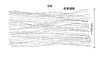
- FIG. 3 shows a schematic cross-sectional view of the expanded stampable sheet.
- the inner carbon fibers are laminated in layers, and voids are generated so that the layers are separated.
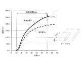
- FIG. 4 shows an example of a temperature profile when a sample obtained by cutting this stampable sheet into 80 mm ⁇ 50 mm is heated by the preheating device.
- the high frequency oscillation output at this time is 200 W, and the electrode heating temperature is 250 ° C.
- the upper electrode descends and comes into contact with the stampable sheet.
- high-frequency oscillation starts.
- the upper electrode separates and simultaneously stops high-frequency oscillation. To do.
- the high-frequency oscillation may be stopped simultaneously with the start of the separation of the upper electrode as described above, or may be continued for a predetermined time even during or after the separation of the upper electrode.
- the stampable sheet reaches the expansion start temperature of 190 ° C.
- its expansion is suppressed by the heating electrode, that is, the expansion suppressing member, and after reaching 260 ° C. within the optimum heating range, Expansion begins only after the gaps are separated.
- the heating device incorporates an automatic matching tracking circuit and a reflected wave measuring circuit, and the reflected wave energy during high-frequency oscillation is 2 W or less (that is, the matching efficiency is 99% or more).
- the matching efficiency may be 100%.
- the temperature was measured by combining an optical fiber thermometer FL-2000 manufactured by Anritsu Keiki Co., Ltd. with a fluorescent optical fiber thermometer probe FS-1M, and a diameter of 1.8 mm with a hole in the end surface of the stampable sheet as shown on the right side of FIG. Measurement is performed by inserting the probe into a small hole having a depth of 15 mm.
- the broken line in the figure is the temperature profile when heating is performed without high-frequency oscillation, that is, only by heat transfer from the heating electrode.
- the temperature difference between the two about 70 ° C. around 70 s
- the temperature difference between the two can be said to be the effect of heating by high frequency.
- the white circles (without high-frequency oscillation) and black circles (with high-frequency oscillation) in the figure are measured with a radiation thermometer (THI-500, manufactured by TASCO) immediately after the upper electrode is separated from the upper electrode in 70 s. It is. Those applied with high frequency are considered to show that the temperature difference between the measurement with the temperature probe is small and the temperature difference between the inside and the surface is small, that is, the effect of internal heating by high frequency is exhibited.
- TTI-500 radiation thermometer
- FIG. 5 shows the heating results at different frequencies. Measurement was performed by replacing the high-frequency power source, matching circuit, and the like of the preheating device of the example. The electrode is not heated. Although only 27.12 MHz has a slight temperature rise, it can be seen that heating is performed at any frequency. Equivalent temperature when stampable sheets of the same size are heated with the conventional atmosphere heating (manufactured by Yamato Kagaku Co., Ltd., vacuum drying furnace DP-21 is used at 260 ° C, normal pressure, built-in heater 680W) It took 4-5 minutes to reach the expanded state.
- the preheating device as compared with the heating device according to the prior art, the temperature difference between the surface and the inside is less likely to be generated, and the stampable sheet is preliminarily prepared without generating a gap in a short time. It is possible to heat.
- a sample such as carbon fiber itself or a carbon fiber composite material such as a stampable sheet in this preheating device
- local leak or spark may occur between the electrode and the sample depending on the composition of the sample. is there.
- a material for the insulating layer a material having excellent heat resistance and being less likely to be heated at a high frequency and having a small dielectric loss is preferable.
- fluorine-based resins such as PTFE (Teflon (registered trademark)), polyamide-based resins (trade name: Kapton, etc.), PPS resins, inorganic materials such as ceramics, and the like are preferable.
- a sheet or film material made of these may be sandwiched between the sample and the electrode, or the electrode itself may be coated with a fluorine-based resin, ceramic, or the like.
- leaks and sparks are more frequently generated between the lower electrode that is grounded than the upper electrode and the sample, and an insulating layer is provided only between the lower electrode and the sample. Is preferred.
- the stampable sheet which is a carbon fiber composite material
- a high frequency 10 MHz-100 MHz.
- FIG. 6 shows the results of heating carbon fiber, carbon fiber composite material, and resin from room temperature under the conditions of 40.68 MHz, 200 W, 30 seconds using the preheating device of the example.
- the sample surface after heating was measured with the above-mentioned radiation thermometer.
- the size, shape, mass, and physical properties (carbon fiber content, specific heat, thermal conductivity, etc.) of each sample are different and of course not a quantitative comparison, but it is certain that all materials are heated. That is, when the carbon fiber composite material is heated at a high frequency, it is considered that both the carbon fiber and the resin are heated by the high frequency to some extent.
- the effect of induction heating in the second term of the above formula or the effect of heating by the third term current can be considered.
- microwave heating using a microwave band of higher frequency.
- 2.45 GHz which is one of the ISM bands, is frequently used.
- the present inventors have also confirmed the phenomenon of ignition in about 20 seconds when a carbon fiber bundle is heated in a microwave oven set at 200 W.
- the high frequency band is considered to be more suitable than the microwave band.
Landscapes
- Engineering & Computer Science (AREA)
- Mechanical Engineering (AREA)
- Physics & Mathematics (AREA)
- Thermal Sciences (AREA)
- Casting Or Compression Moulding Of Plastics Or The Like (AREA)
- Constitution Of High-Frequency Heating (AREA)
- Heating, Cooling, Or Curing Plastics Or The Like In General (AREA)
- Moulding By Coating Moulds (AREA)
- Blow-Moulding Or Thermoforming Of Plastics Or The Like (AREA)
- Molding Of Porous Articles (AREA)
Abstract
表面と内部の温度差を生じさせにくく、短時間で、かつ極力空隙を生じさせずに、スタンパブルシートを予備加熱する加熱装置及び加熱方法を提供すること。具体的には、加熱により内部に空隙を生じながらその見掛け体積が膨張する性状を有する材料からなる被加熱物の加熱装置であって、少なくとも該被加熱物が前記膨張が開始する温度(膨張開始温度)以上に到達するまで、前記被加熱物と接触し前記被加熱物の膨張を抑制する膨張抑制部材を有することを特徴とする加熱装置及び加熱方法を提供する。
Description
本発明は、加熱により内部に空隙を生じながらその見掛け体積が膨張する性状を有する材料の加熱装置及び加熱方法に関わるものであり、また、高周波により非加熱物を加熱する高周波加熱装置および高周波加熱方法にも関連するものである。
これまで、炭素繊維及び炭素繊維複合材料は、軽量、高強度、高弾性率といった特性を生かして、航空宇宙、スポーツレジャーといった分野で主に用いられてきていた。この分野は、性能、機能優先のため材料コスト、生産コストが多少高くても通用する分野であったと言える。現在、軽量化、省エネルギーといった観点から、自動車、エネルギー関連、一般産業機械といった分野への炭素繊維及び炭素繊維複合材の応用が期待されており、より低コストで大量生産が可能な炭素繊維複合材料およびその製造、成型方法が求められている。炭素繊維複合材部品の低コスト、大量生産に当たってはその生産速度、成型速度の向上が必須であり、その解決策のひとつとして期待されているのが熱可塑性樹脂の採用である。
従来の炭素繊維複合材は、エポキシ等に代表されるマトリクス樹脂としての熱硬化性樹脂中に炭素繊維を分散等させて内包させた形態が主流であり、機械的強度や弾性率に優れるものの、それを用いた部品製造に当たっては、人手が主流の成型工程、オートクレーブと称する焼成炉内で数時間にも渡る加熱工程が必要であるなど、自動車、エネルギー関連、一般産業機械といった分野に対しては、必ずしもその生産コスト、生産性は十分なものではなかった。
一方、熱可塑性樹脂による炭素繊維複合材料は、機械的強度や弾性率はやや劣るものの、熱可塑性であることから特に成型性、成型速度に優れ、さらに、既存の射出、押出、プレスといった成型方法や装置がそのまま、或いは軽度の変更で使用可能であるといった特長も有する。
特に大量生産が要求される自動車及び自動車部品用途において、既存の射出成型方法、装置やプレス成型方法、装置が転用等できるメリットは大きく、そこそこの強度で済む部材の熱可塑性炭素繊維複合材の適用検討が進んでいる。
熱可塑性炭素繊維複合材料のひとつの形態として期待されているのが、スタンパブルシート、LFTP(Long Fiber Thremoplastic)、熱可塑性SMC(Sheet Molding Compound)などと呼ばれるシート状、板状の炭素繊維複合材中間素材である(以下スタンパブルシートと総称する)。これらは、射出成型用の炭素繊維複合材よりは比較的長繊維寄りの(0.1~10cm、好ましくは1~7cm、さらに好ましくは2~5cm)状態に切断された炭素繊維若しくは炭素繊維束を、マトリクス樹脂たる熱可塑性樹脂中にランダムに配行、分散させて内包させた構造を有するものである。厚みは1mmから10mm程度のシート状、平板状の中間素材として提供されることが多い。
このスタンパブルシートを、その熱可塑性樹脂の軟化開始温度以上に加熱(予備加熱と称する)して軟化させた状態でプレス加工することにより、所望の形状が付与された成型品が製造できる。これはいわば、板金プレス加工における板金材がスタンパブルシートに置き換わったものと考えてもよい。
さて、板金プレス加工における板金材は基本的に等方性材料である金属であり、よって成型前に平面状であった板金材がしわや破れなしに立体形状に塑性変形可能なわけである。即ち板金プレス加工おける板金材を炭素繊維複複合材に置き換えるには、炭素繊維複合材に等方性の性状を付与することが必須となる。然るに、炭素繊維複合材に強度、剛性を犠牲にすることなく等方性の性状を付与する事は容易ではない。
一般に、平面状の炭素繊維複合材の製造方法としては、相当長を有する炭素繊維の単糸若しくは繊維束を、配列、織り、編みによって平面状にいわば炭素繊維の布帛に仕上げ、該布帛に熱硬化又は熱可塑の樹脂を含浸させて製造するのが通例である。このため、炭素繊維(束)の配行している方向とそれ以外の方向では、弾性、剛性等の物性が異なる非等方性材料となるのが普通である。
このような非等方性材料を板金プレス同様のプレス加工を施すと、材料の変形がその非等方性の影響を受け、易変形部、非易変形部、非変形部が発生し、所望の成型形状が得られない場合が殆どである。これは、布帛を無理やり立体形状に成型した場合に、布帛が余ってしわが発生する部分、布帛が不足して緊張~破断する部分が発生することからも容易に類推される。
一方、炭素繊維複合材を射出成型で成型することも可能であり、この場合、炭素繊維又は繊維束はその長さが1mm程度以下に切断されたものが用いられるのが通例である。各炭素繊維又は繊維束は主として射出成型前の混錬、撹拌によって、ランダムに配行、分散し、よって炭素繊維複合材として擬似等方的的な性状が実現されている。よって斯様な短繊維からなる炭素繊維複合材ならばプレス加工が容易となる場合も考えられるが、炭素繊維又は繊維束長が相対的に短いこと起因する、複合材料としての強度、剛性が劣ることは如何ともし難い場合が多い。
即ち、スタンパブルシートはプレス加工に必要な等方性性状を確保しつつ、かつ、必要十分な強度、剛性の実現を、その炭素繊維又は繊維束の長さ、配行状態を最適化することにより実現したものともいえる。
スタンパブルシートの製法は概略次の様な工程で行われることが多い。まず、適度に開繊された炭素繊維束を所望の長さに切断する。これを平面上に自然落下、振動、撹拌等によって、ランダムに配行させつつ積層させる。このとき、同時に粉粒体形状の熱可塑性樹脂を供給して、炭素繊維束と粉粒体形状の熱可塑性樹脂が均一に交じり合った層を形成させる場合もある。あるいはフィルム状の熱可塑性樹脂と炭素繊維束層を交互に積層させていくこともある。いずれの方式にせよ炭素繊維束層は綿状といってもよく、その見かけ厚みは、成型後の厚みよりも遙かに厚い。次に、これを圧縮させながら加熱溶融した熱可塑性樹脂を炭素繊維束間に含浸させる、或いは、既に存在する粉粒体形状またはフィルム状の熱可塑性樹脂を溶融させて炭素繊維束中に含浸させ、その後冷却して所望の厚みのスタンパブルシートを得る。炭素繊維の体積含有割合、いわゆるVfは30%程度が普通である。
以上述べた製法に起因するが、スタンパブルシート内では積層された炭素繊維束は圧縮された状態にある。したがって、スタンパブルシートが予備加熱されてその熱可塑性樹脂が軟化すると、積層された炭素繊維束の圧縮が開放され、スタンパブルシート内(各炭素繊維束間)に空隙を生じさせながら、その厚み方向に見かけ膨張するのが普通である。プレス成型に当たっては予備加熱によって見掛け膨張したスタンパブルシートをプレス成型の金型間に置き、金型締めして成型することで、前記空隙は解消し所望の成型が行われる。
尚、空隙を生じさせながら見掛け体積が膨張するという性状は、炭素繊維を用いたスタンパブルシートに限定されるものでなく、スタンパブルシート内で繊維束層が圧縮された状態にあるものであれば、ガラス繊維、金属繊維、ポリイミドに代表される有機繊維などを問わず、同様に見られる性状である。
石川県工業技術試験所 平成24年度研究方向vol.24
エレクトロヒートハンドブック 一般社団法人日本エレクトロヒートセンター編 第1版第1冊 2015.9.25刊
公益法人日本化学会主催 日本化学会秋季事業 第4回CSJ化学フェスタ2014予行集講演番号H2-08
スタンパブルシートのプレス成型に当たっては、少なくともその熱可塑性樹脂の軟化開始温度以上に予備加熱してからプレス成型することは前述したとおりである。この予備加熱には最適温度範囲があり予備加熱温度はそれ以上でもそれ以下でも好ましくない。
プレス成型に対して熱可塑性樹脂が適度な流動性を示す温度範囲があり、この適正範囲内に予備加熱することが必要である。これ以下の温度では熱可塑性樹脂の流動性が不足し成型不良が発生したり、逆に、高すぎると樹脂が流動しすぎるほか、樹脂そのものの分解、酸化、低分子量成分の気化といった変質(劣化)が著しいといった問題がある。これは成型後の成型品の強度不足、経時劣化の促進といった問題に繋がることがある。
従来技術に於いては、予備加熱には雰囲気加熱や赤外線加熱を用いることが多い。即ちスタンパブルシートを、電熱等公知の熱源を有する炉内に静置して加熱する雰囲気加熱や、遠~近(場合によっては可視領域も含む)赤外ランプからの赤外線等の輻射により加熱する方法を用いる。
このような従来技術においては、次のような問題がある。
まず、雰囲気加熱や赤外線加熱は被加熱物の表面からの加熱であり、スタンパブルシートの表面とその内部に温度差が出来てしまう場合が多い(文献1)。スタンパブルシートは熱可塑性樹脂を主成分としたものであり金属等に比べれば熱伝導性は低い。このため表面が最適温度範囲内に達したとしても内部は最適温度下限にも達しない場合が発生する。又、逆に内部が最適温度範囲に到達したときには、表面は最適温度範囲上限を超えてしまう場合もある。
まず、雰囲気加熱や赤外線加熱は被加熱物の表面からの加熱であり、スタンパブルシートの表面とその内部に温度差が出来てしまう場合が多い(文献1)。スタンパブルシートは熱可塑性樹脂を主成分としたものであり金属等に比べれば熱伝導性は低い。このため表面が最適温度範囲内に達したとしても内部は最適温度下限にも達しない場合が発生する。又、逆に内部が最適温度範囲に到達したときには、表面は最適温度範囲上限を超えてしまう場合もある。
この問題を軽減するためには、基本的には加熱源の出力を下げ、かつ時間をかけてゆっくり加熱することで、表面と内部の温度差を極力小さくするのが好ましい。雰囲気温度に於いては熱源の出力、赤外線加熱に於いては赤外線ランプの出力を下げ、長時間加熱することが必要となり、加熱時間が長くなるという問題が発生する。
又、被加熱物であるスタンパブルシートの温度をモニタしながら、適宜加熱源の出力を調整する等の手段も可能であるが、加熱装置が複雑、高価になり、かつその操作、制御も煩雑になるという問題も発生する。
さらに、スタンパブルシートのプレス成型に要する時間(通常1分程度で可能)よりも、予備加熱に要する時間が長くなる場合も発生する。この場合には、予備加熱からプレス成型の工程スループットを維持するためには、1台のプレス機に対して予備加熱装置が複数台必要になり、設備費、設置場所の増大といった問題にも繋がる。
さらに、前述したようにスタンパブルシートは加熱により内部に空隙を生じながら見掛け膨張する。軟化開始温度は前述の最適温度範囲よりは低温であるのが普通であり、よってスタンパブルシートは、最適温度範囲に到達する以前から空隙を生じながら見掛け膨張を開始し、最適温度に到達するまでの間、空隙を生じた状態で加熱され続ける。
空隙が発生し始めると、当該空隙は熱的には絶縁物に近くマクロに見た熱伝達率も下がると予想される。これは、前述の内部、表面との温度差をさらに助長させると考えられる。
また、熱可塑性樹脂は前述の最適温度範囲内又はそれ以下といえども、長時間の加熱によっては、前述した分解、酸化、低分子量成分の気化といった変質(劣化)が発生する場合がある。特にそれは表面において著しく、空隙を生じさせた状態では空隙による実質表面の増大も相まって、より、分解、酸化、低分子量成分の気化といった変質(劣化)が促進されるという問題も発生する
即ち、従来技術に付きまとうこれらの問題を回避するため、表面と内部の温度差を生じさせにくく、短時間で、かつ極力空隙を生じさせずに、スタンパブルシートを予備加熱する加熱技術が求められていた。
即ち、従来技術に付きまとうこれらの問題を回避するため、表面と内部の温度差を生じさせにくく、短時間で、かつ極力空隙を生じさせずに、スタンパブルシートを予備加熱する加熱技術が求められていた。
上記課題を解決するために、本願発明によれば、加熱により内部に空隙を生じながらその見掛け体積が膨張する性状を有する材料からなる被加熱物の加熱装置であって、少なくとも該被加熱物が前記膨張が開始する温度(膨張開始温度)以上に到達するまで、前記被加熱物と接触し前記被加熱物の膨張を抑制する膨張抑制部材を有することを特徴とする加熱装置が提供される。
本願発明の好ましい態様によれば、前記被加熱物が平板状の形状を有するものであり、前記加熱装置は、前記膨張抑制部材たる対向する一対の加熱表面間に前記被加熱物を載置し、該一対の加熱表面を前記被加熱物に接触させることにより、前記被加熱物の前記膨張を抑制しながら前記被加熱物を加熱することを特徴とする加熱装置が提供される。
本願発明によるさらに好ましい態様によれば、前記被加熱物の少なくとも一部が前記膨張開始温度以上に到達した後に、前記一対の加熱表面の少なくとも一方と前記被加熱物との接触を解除することを特徴とする加熱装置が提供される。
本願発明によるさらに好ましい態様によれば、前記一対の加熱表面は導電性を有するものであり、前記加熱装置がさらに前記一対の加熱表面間に電磁波を印加するための電磁波発生源を有し、該電磁波によっても前記被加熱物を加熱することを特徴とする加熱装置が提供される。
本願発明によるさらに好ましい態様によれば、前記電磁波の周波数が10MHz以上100MHz以下の範囲のものであることを特徴とする加熱装置が提供される。
本願発明によるさらに好ましい態様によれば、前記被加熱物と前記一対の加熱表面の少なくとも一方との間に絶縁材層が存在することを特徴とする加熱装置が提供される。
本願発明によるさらに好ましい態様によれば、前記被加熱物が、マトリクス樹脂中に強化繊維を内包する構造を有するものであることを特徴とする加熱装置が提供される。
本願発明によるさらに好ましい態様によれば、前記強化繊維の少なくとも一部が炭素繊維であることを特徴とする加熱装置が提供される。
本願発明によるさらに好ましい態様によれば、前記マトリクス樹脂が熱可塑性の樹脂を含むものであることを特徴とする加熱装置が提供される。
本発明の趣旨は、まず、加熱時間を短くする観点から、スタンパブルシートを加熱表面と接触させて接触伝熱による急速加熱の効果を利用し、さらに、表面と内部の温度差を低減させるべく、該表面から高周波を印加していわゆる高周波加熱による内部加熱の効果を発揮させたものである。
さらには、該表面によって、スタンパブルシートの見かけ体積膨張を抑制するという効果もあわせて発揮させている。
高周波、マイクロ波など電磁波による加熱技術は、各種ハンドブック的書籍(非特許文献2)が発刊されていることからも分かるようにように、加熱、溶解、熱処理、接着、解凍などを目的に遍く用いられている加熱技術である。
高周波領域において、各種産業分野において加熱等の目的で使用される周波数は、日本国内においては実質的には13.56MHz、27.12MHz,40.68MHzの3周波数帯がその使用が認められている(いわゆるISMバンド周波数)。尚、この3周波数帯以外の周波数の高周波も漏洩電磁界強度が規定値以下となるような対策を施せば、産業用途として使用可能である。
高周波、マイクロ波など電磁波による加熱は、式(1)で示される電磁波と物質の相互作用によるものである。
P=πfε0εr”|E|2+πfμ0μr”|H|2+(1/2)σ|E|2
・・(1)
ここで、
P:単位体積あたりのエネルギー損失(=発熱量)[W/m3]
π:円周率
f:電磁波の周波数[s-1]
ε0:真空の誘電率[F/m]
εr”:物質の誘電損失[F/m]
E:電磁波の電場[V/m]
μ0:真空の透磁率[H/m]
μr”:物資の磁気損失[H/m]
H:電磁波の磁場[A/m]
σ:物質の電気伝導度[S/m]
である。
・・(1)
ここで、
P:単位体積あたりのエネルギー損失(=発熱量)[W/m3]
π:円周率
f:電磁波の周波数[s-1]
ε0:真空の誘電率[F/m]
εr”:物質の誘電損失[F/m]
E:電磁波の電場[V/m]
μ0:真空の透磁率[H/m]
μr”:物資の磁気損失[H/m]
H:電磁波の磁場[A/m]
σ:物質の電気伝導度[S/m]
である。
式(1)において、πfε0εr”|E|2 と記されている第1項は誘電項とも呼ばれ、印加される電磁波の電界によって生じる誘電損失による発熱を示す。
また、πfμ0μr”|H|2 と記されている第2項は磁性項ともよばれ、印加される電磁波の交番磁界によって、多くは導電体である被加熱物に生じる渦電流のジュール発熱による誘導発熱を示す項である。
更に、(1/2)σ|E|2 と記されている第3項は電流項と呼ばれ、印加される電磁波の電界によって生じる静電誘導電流によるジュール発熱を表す。
また、πfμ0μr”|H|2 と記されている第2項は磁性項ともよばれ、印加される電磁波の交番磁界によって、多くは導電体である被加熱物に生じる渦電流のジュール発熱による誘導発熱を示す項である。
更に、(1/2)σ|E|2 と記されている第3項は電流項と呼ばれ、印加される電磁波の電界によって生じる静電誘導電流によるジュール発熱を表す。
第1項が支配的な場合を誘電加熱と呼び、第2項が支配的な場合を誘導加熱と呼ぶ場合もある。
誘電加熱は、被加熱物が絶縁体(誘電体)の場合に多く用いられ、プラスチック、木材、紙、接着剤等の加熱、乾燥などの目的で用いられることが多い。いわゆる電子レンジでの2.45GHzのマイクロ波による水分子の誘電加熱はその代表例である。
高周波を用いた誘電加熱装置の形態としては、図1に概略示すように、対向する一対の電極間に被加熱物を配置し、両電極間に高周波を印加して、被加熱物を高周波誘電加熱する形態のものが多い。電極形状は図1では略平板状となっているが、電極面を曲面等で構成する等、被加熱物の形状に合わせて、電極形状を変更することも可能である。
高周波を用いた誘電加熱装置の形態としては、図1に概略示すように、対向する一対の電極間に被加熱物を配置し、両電極間に高周波を印加して、被加熱物を高周波誘電加熱する形態のものが多い。電極形状は図1では略平板状となっているが、電極面を曲面等で構成する等、被加熱物の形状に合わせて、電極形状を変更することも可能である。
一方、誘導加熱は、被加熱物が導電体の場合が多く、鉄鋼材料への焼入れ等の熱処理、粉末冶金における材料の溶解、加熱などが代表的なものである。いわゆるIH調理器など称されている交番磁界を用いた加熱調理器具もこの応用ともいえる。
尚、電磁波による加熱方法で、第3項(電流項)が支配的となっている応用例は少ない。
マイクロ波、高周波など電磁波による加熱の特徴として次の3点が考えられる。
特徴1:急速加熱
一般的な加熱方法は、輻射加熱を除けば加熱源からの熱エネルギーが伝導、対流によって、いわばゆっくりと伝播してくるのが普通である。これに対し、電磁波による加熱は加熱に要するエネルギーが電磁波の形態で空間を光速で伝達して来るとも表現でき、急速な加熱が出来るのが特徴のひとつである。
特徴2:内部加熱
電磁波は被加熱物の物性にも因るが、その内部に浸透、透過しながら被加熱物吸収され、熱エネルギーに変換される。したがって、加熱を被加熱物の表面からだけでなく内部から行なうことも可能である。
特徴3:選択加熱
被加熱物の物性によって、吸収される電磁波の波長(周波数)選択性がある。よって、複数の物質の混合物であっても、電磁波の波長を選択すれば特定の物質だけを選択的に加熱することも可能である。
特徴1:急速加熱
一般的な加熱方法は、輻射加熱を除けば加熱源からの熱エネルギーが伝導、対流によって、いわばゆっくりと伝播してくるのが普通である。これに対し、電磁波による加熱は加熱に要するエネルギーが電磁波の形態で空間を光速で伝達して来るとも表現でき、急速な加熱が出来るのが特徴のひとつである。
特徴2:内部加熱
電磁波は被加熱物の物性にも因るが、その内部に浸透、透過しながら被加熱物吸収され、熱エネルギーに変換される。したがって、加熱を被加熱物の表面からだけでなく内部から行なうことも可能である。
特徴3:選択加熱
被加熱物の物性によって、吸収される電磁波の波長(周波数)選択性がある。よって、複数の物質の混合物であっても、電磁波の波長を選択すれば特定の物質だけを選択的に加熱することも可能である。
本発明は、この第2の効果を積極的に利用し、表面と内部の温度差を生じさせにくく、短時間で加熱するという課題を解決しているといえる。
本発明に寄れば、表面と内部の温度差を生じさせにくく、短時間で、極力空隙を生じさせずにスタンパブルシートを予備加熱できる装置が実現できる。
本明細書の以降の記載に於いては、特に断らない限り10MHz~100MHzの範囲の電磁波を高周波と呼ぶこととする。
本発明に関わる、予備加熱装置1の該略図を図1に示す。
対向する一対の加熱電極10(その対向する表面が本発明にいう加熱表面であり、該加熱電極が膨張抑制部材を兼ねる)間に被加熱物11が配置される。加熱電極10は導電材料からなり、一方(図では下側)の加熱電極(下電極2)は加熱装置1の筐体12と電気的に絶縁され接地されている。他方の電極(上電極3と呼ぶ)も、予備加熱装置1の筐体12等からは電気的に絶縁され、マッチング装置5を介して高周波電源6(電磁波発生源)に接続される。加熱電極10の導電材料としてはアルミニウム系合金、ステンレスなどが使用できる。ステンレスは非磁性のものが好ましい。
対向する一対の加熱電極10(その対向する表面が本発明にいう加熱表面であり、該加熱電極が膨張抑制部材を兼ねる)間に被加熱物11が配置される。加熱電極10は導電材料からなり、一方(図では下側)の加熱電極(下電極2)は加熱装置1の筐体12と電気的に絶縁され接地されている。他方の電極(上電極3と呼ぶ)も、予備加熱装置1の筐体12等からは電気的に絶縁され、マッチング装置5を介して高周波電源6(電磁波発生源)に接続される。加熱電極10の導電材料としてはアルミニウム系合金、ステンレスなどが使用できる。ステンレスは非磁性のものが好ましい。
下電極2は予備加熱装置1の筐体12に絶縁部材4を介して固定されており、上電極3は電極昇降装置9よって下電極2に対し図中矢印Aで示すように上下動作可能となっている。
上電極2、下電極3とも内部にヒータ及び温度度測定素子を有し(図示せず)、温度制御装置(図示せず)によって電極全体(即ち加熱表面も)を所望の温度に加熱する。電極の加熱温度は被加熱物11中の熱可塑性樹脂の軟化開始温度以上かつ最適加熱範囲上限以下が好ましい。この温度範囲内であれば、どんなに長時間被加熱物11が上電極2または下電極3と接触したとしても、被加熱物11の温度は最適加熱範囲上限を超えることが無く好適である。
被加熱物11は下電極2上に載置される。次いで上電極3が電極昇降装置9によって降下し所定圧力で被加熱物11に密着する。同時に高周波電源6から高周波が発振される。被加熱物11は接触した加熱電極10からの熱伝導による表面からの加熱と印加された高周波による内部から加熱、双方で加熱される。
被加熱物11の温度が軟化開始温度以上となっても、被加熱物11は膨張抑制部材たる上下電極2および3に挟まれており、内部に空隙を生じながらその見かけ体積が膨張することはない。尚、当然ではあるが上電極3の前記所定圧力は、被加熱物11の膨張によって生じる圧力より大きくなければならない。
所定の加熱時間経過後、又は、別途設けた被加熱物11の温度測定装置(図示せず)の測定結果より、被加熱物11が最適温度範囲内の所定の温度に到達すると、上電極3を上方に離間させる。この瞬間から被加熱物11は膨張を開始する。
高周波は、上電極3が離間を開始した時点で発振を止めても良いし、上電極3が離間開始した後も所定の時間、又は上電極3が所定の高さに到達するまで、印加を継続しても良い。
上電極3が所定の高さに到達すれば、被加熱物11を加熱電極10間から取り出し、プレス工程に搬送する。
上記態様に於いては、被加熱物11が膨張を開始する軟化開始温度に到達した後も、最適加熱温度に達するまでの間、膨張抑制部材たる上下の加熱電極10でその膨張が抑制されるため、被加熱物11が膨張状態にある時間が短縮され、空隙を生じている時間が極力短く出来るという効果が発揮できる。
さらに、加熱電極10からの熱伝導による被加熱物11の表面からの加熱と、高周波による内部からの加熱を併用することで、加熱時間の短縮と、被加熱物11の表面と内部の温度差低減の効果が発揮できる。
(実施例)
以下に、本発明の実施例を述べる。
予備加熱装置として山本ビニター株式会社製、コンパクト型高周波ウェルダーYRP-400T-RCを改造した装置を用いた。該装置の高周波発振周波数は40.68MHz、最大出力400Wである。
(実施例)
以下に、本発明の実施例を述べる。
予備加熱装置として山本ビニター株式会社製、コンパクト型高周波ウェルダーYRP-400T-RCを改造した装置を用いた。該装置の高周波発振周波数は40.68MHz、最大出力400Wである。
加熱電極はアルミニウム製、横85mm×縦55mm×厚み15mmの大きさで、内部にシーズヒータ(200W)及び温度センサを内蔵し、加熱表面温度最大300℃に維持可能である。上電極はロボシリンダ(登録商標)に直結され、スタート位置、ストップ位置、及びそれらにタイミング、移動速度などを任意に設定して上下動作できるようになっている。
被加熱物たるスタンパブルシートは、厚み3mm、ナイロン6系熱可塑性樹脂に体積含有量Vf=30%で、炭素繊維束(長さ3~5cm)をランダムに配行、分散させたものである。該スタンパブルシートの最適加熱温度範囲は下限250℃、上限290℃である。
該スタンパブルシートを恒温槽内に静置し、ゆっくりと加熱していったときの温度と膨張の関係を図2に示す。該スタンパブルシートは190℃付近より膨張を開始し、元の厚み(3mm)の5倍程度である15mm程度まで見かけ膨張する。図3に膨張した該スタンパブルシートの断面模式図を示す。内部の炭素繊維は層状に積層されており、その層間が剥離する様に空隙が発生している。
このスタンパブルシートを80mm×50mmに切り出したサンプルを、該予備加熱装置で加熱したときの温度プロファイルの一例を図4に示す。
このときの高周波発振出力200W、電極の加熱温度250℃である。横軸10秒において、上電極が降下してスタンパブルシートと接触、同時に高周波の発振が開始する、高周波は60秒間発振し、横軸70秒において上電極が離間し、同時に高周波の発振も停止する。
なお、高周波の発振は上述のように上電極の離間開始と同時に停止しても構わないし、上電極の離間動作中或いは離間完了後も所定の時間継続させてもかまわない。
図4より分かるように、スタンパブルシートは膨張開始温度190℃に達しても加熱電極即ち膨張抑制部材でその膨張が抑制されており、最適加熱範囲内である260℃に達して後、上電極が離間した後に始めて膨張が開始する。
図4より分かるように、スタンパブルシートは膨張開始温度190℃に達しても加熱電極即ち膨張抑制部材でその膨張が抑制されており、最適加熱範囲内である260℃に達して後、上電極が離間した後に始めて膨張が開始する。
また、該加熱装置には自動マッチング追従回路、反射波測定回路も組み込まれており、高周波発振中の反射波エネルギーは2W以下(即ちマッチング効率99%以上)であり、以下の議論に於いてはマッチング効率は100%としても差し支えない。
温度測定は、安立計器株式会社製蛍光式光ファイバー温度計FL-2000と蛍光式光ファイバー温度計プローブFS-1Mを組み合わせ、図4右側に示すようにスタンパブルシートの端面に窄孔した直径1.8mm、深さ15mmの小孔に該プローブを挿入して測定している。
温度測定は、安立計器株式会社製蛍光式光ファイバー温度計FL-2000と蛍光式光ファイバー温度計プローブFS-1Mを組み合わせ、図4右側に示すようにスタンパブルシートの端面に窄孔した直径1.8mm、深さ15mmの小孔に該プローブを挿入して測定している。
図中破線は高周波の発振無し、すなわち加熱電極からの伝熱だけで加熱されたときの温度プロファイルである。両者の温度差(70s付近で70℃程度ある)が高周波による加熱の効果といえる。
図中白丸(高周波発振無し)及び黒丸(高周波発振あり)は、70sで上電極が離間した直後のスタンパブルシートの上面の温度を放射温度計(TASCO社製、THI-500)で測定したものである。高周波を印加したものは、温度プローブによる測定との温度差が小さく、内部と表面の温度差が小さいこと、即ち高周波による内部加熱の効果が発揮されていることを示していると考えられる。
図5には異なる周波数での加熱結果を示す。実施例の予備加熱装置の高周波電源、マッチング回路等を取り替えて測定した。電極加熱は行っていない。27.12MHzのみやや温度上昇が小さいが、いずれの周波数でも加熱が行われていることがわかる。
同じ大きさのスタンパブルシートを、従来技術である雰囲気加熱(ヤマト科学株式会社製、真空乾燥炉DP-21を260℃設定、常圧で使用。内蔵ヒータ680W)で加熱した場合、同等の温度、膨張状態となるのに4~5分を要した。
同じ大きさのスタンパブルシートを、従来技術である雰囲気加熱(ヤマト科学株式会社製、真空乾燥炉DP-21を260℃設定、常圧で使用。内蔵ヒータ680W)で加熱した場合、同等の温度、膨張状態となるのに4~5分を要した。
以上の結果より、本発明による予備加熱装置では、従来技術による加熱装置に比して、表面と内部の温度差を生じさせにくく、短時間で極力空隙を生じさせずに、スタンパブルシートを予備加熱することが可能である。
尚、本予備加熱装置において炭素繊維そのものや、スタンパブルシートなどの炭素繊維複合材等のサンプルを加熱するに当たって、サンプルの組成によっては電極とサンプル間で局所的なリークやスパークが発生する場合がある。このような場合、加熱電極とサンプルの間に絶縁層を設ければ、リークやスパークが抑制でき好適である。絶縁層の材質としては、耐熱性に優れかつそれ自体が高周波で加熱されることの少ない、誘電損失の小さい材質が好ましい。具体的にはPTFE(テフロン(登録商標))などのフッ素系樹脂、ポリアミド系樹脂(商標名カプトンなど)、PPS樹脂、セラミック等の無機材料などが好ましい。これらでできたシート、フィルム材をサンプルと電極間に挟んでもよく、また電極自体にフッ素系樹脂、セラミック等をコーティングすることでもよい。
本発明者の観察によれば、上電極に比べアース接地されている下電極とサンプル間でリークやスパークが発生することが相対的に多く、下電極とサンプル間にのみ絶縁層を設けるのも好適である。
さて、本発明によれば10MHz-100MHzの高周波を用いて炭素繊維複合材であるスタンパブルシートを加熱している。このときスタンパブルシートの構成要素である炭素繊維とナイロン6系樹脂のどちらが主体的に加熱されているかは興味深い問題である。
図6には実施例の予備加熱装置を用い、40.68MHz、200W、30秒の条件で炭素繊維や炭素繊維複合材、樹脂を室温から加熱した結果である。加熱後のサンプル表面を前述の放射温度計で測定した。各サンプルの大きさ、形状、質量、物性(炭素繊維含有量、比熱、熱伝導度など)が異なりもちろん定量的な比較はではないが、いずれの材料も加熱されることは確かである。即ち炭素繊維複合材を高周波で加熱した場合、程度の差はあれ炭素繊維と樹脂双方とも高周波により加熱されていると考えられる。
図6には実施例の予備加熱装置を用い、40.68MHz、200W、30秒の条件で炭素繊維や炭素繊維複合材、樹脂を室温から加熱した結果である。加熱後のサンプル表面を前述の放射温度計で測定した。各サンプルの大きさ、形状、質量、物性(炭素繊維含有量、比熱、熱伝導度など)が異なりもちろん定量的な比較はではないが、いずれの材料も加熱されることは確かである。即ち炭素繊維複合材を高周波で加熱した場合、程度の差はあれ炭素繊維と樹脂双方とも高周波により加熱されていると考えられる。
炭素繊維そのものの高周波による加熱のメカニズムについては、前掲の式第2項の誘導加熱の効果、もしくは、第3項電流項による加熱の効果も考えられる。
さて、電磁波を用いた加熱方法としてはより高い周波数のマイクロ波帯を用いるマイクロ波加熱もある。マイクロ波加熱に於いてはISMバンドのひとつである2.45GHzが多用される。このマイクロ波でも炭素繊維は容易に加熱できることは知られており、逆に加熱されすぎる故、文献3で述べられている、炭素繊維複合材において炭素繊維と樹脂界面で樹脂の過昇温の問題も知られている。本発明者らも200W設定の電子レンジで炭素繊維束を加熱したところ20秒程度で発火する現象を確認している。
さて、電磁波を用いた加熱方法としてはより高い周波数のマイクロ波帯を用いるマイクロ波加熱もある。マイクロ波加熱に於いてはISMバンドのひとつである2.45GHzが多用される。このマイクロ波でも炭素繊維は容易に加熱できることは知られており、逆に加熱されすぎる故、文献3で述べられている、炭素繊維複合材において炭素繊維と樹脂界面で樹脂の過昇温の問題も知られている。本発明者らも200W設定の電子レンジで炭素繊維束を加熱したところ20秒程度で発火する現象を確認している。
一方、本発明に用いた高周波領域であれば、図6に示したように炭素繊維単独でも発火することはなく、比較的緩やかな加熱が可能であり、炭素繊維複合材の電磁波による加熱では、マイクロ波帯よりも高周波帯の方が適していると考えられる。
1 予備加熱装置
2 下電極
3 上電極
4 絶縁部材
5 マッチング回路
6 高周波電源
7 上電極ベース
8 連結部材
9 電極昇降装置
10 加熱電極
11 被加熱物
12 筐体
2 下電極
3 上電極
4 絶縁部材
5 マッチング回路
6 高周波電源
7 上電極ベース
8 連結部材
9 電極昇降装置
10 加熱電極
11 被加熱物
12 筐体
Claims (12)
- 加熱により内部に空隙を生じながらその見掛け体積が膨張する性状を有する材料からなる被加熱物の加熱装置であって、少なくとも該被加熱物が前記膨張が開始する温度(膨張開始温度)以上に到達するまで、前記被加熱物と接触し前記被加熱物の膨張を抑制する膨張抑制部材を有することを特徴とする加熱装置。
- 前記被加熱物が平板状の形状を有するものであり、前記加熱装置は、前記膨張抑制部材たる対向する一対の加熱表面間に前記被加熱物を載置し、該一対の加熱表面を前記被加熱物に接触させることにより、前記被加熱物の前記膨張を抑制しながら前記被加熱物を加熱することを特徴とする請求項1に記載の加熱装置。
- 前記被加熱物の少なくとも一部が前記膨張開始温度以上に到達した後に、前記一対の加熱表面の少なくとも一方と前記被加熱物との接触を解除することを特徴とする請求項2に記載の加熱装置。
- 前記一対の加熱表面は導電性を有するものであり、前記加熱装置がさらに前記一対の加熱表面間に電磁波を印加するための電磁波発生源を有し、該電磁波によっても前記被加熱物を加熱することを特徴とする請求項2または3のいずれかに記載の加熱装置。
- 前記電磁波の周波数が10MHz以上100MHz以下の範囲のものであることを特徴とする請求項4に記載の加熱方法。
- 前記被加熱物と前記一対の加熱表面の少なくとも一方との間に絶縁材層が存在することを特徴とする請求項2乃至5のいずれかに記載の加熱装置。
- 前記被加熱物が、マトリクス樹脂中に強化繊維を内包する構造を有するものであることを特徴とする請求項1乃至6のいずれかに記載の加熱装置。
- 前記強化繊維の少なくとも一部が炭素繊維であることを特徴とする請求項7に記載の加熱装置。
- 前記マトリクス樹脂が熱可塑性の樹脂を含むものであることを特徴とする請求項7又は8に記載の加熱装置。
- 加熱により内部に空隙を生じながらその見掛け体積が膨張する性状を有する材料からなる被加熱物の加熱方法であって、少なくとも該被加熱物が前記膨張が開始する温度(膨張開始温度)以上に到達するまで、前記被加熱物の膨張を抑制しながら加熱することを特徴とする加熱方法。
- 請求項10に記載の加熱方法であって、前記被加熱物の膨張を抑制つつ、同時に前記被加熱物を高周波によって加熱することを特徴とする加熱方法。
- 前記被加熱物が熱可塑性マトリクス樹脂中に炭素繊維を内包した構造を有するものであることを特徴とする請求項10又は11に記載の加熱方法。
Applications Claiming Priority (2)
| Application Number | Priority Date | Filing Date | Title |
|---|---|---|---|
| JP2015241511A JP6684086B2 (ja) | 2015-12-10 | 2015-12-10 | 加熱装置及び加熱方法 |
| JP2015-241511 | 2015-12-10 |
Publications (1)
| Publication Number | Publication Date |
|---|---|
| WO2017099014A1 true WO2017099014A1 (ja) | 2017-06-15 |
Family
ID=59013101
Family Applications (1)
| Application Number | Title | Priority Date | Filing Date |
|---|---|---|---|
| PCT/JP2016/085892 Ceased WO2017099014A1 (ja) | 2015-12-10 | 2016-12-02 | 加熱装置及び加熱方法 |
Country Status (2)
| Country | Link |
|---|---|
| JP (1) | JP6684086B2 (ja) |
| WO (1) | WO2017099014A1 (ja) |
Citations (2)
| Publication number | Priority date | Publication date | Assignee | Title |
|---|---|---|---|---|
| JP2012206515A (ja) * | 2010-04-02 | 2012-10-25 | Hirotani:Kk | 車両用内装部材の成形方法 |
| JP2014198838A (ja) * | 2013-03-11 | 2014-10-23 | 三菱レイヨン株式会社 | 繊維強化熱可塑性樹脂成形板の製造方法 |
Family Cites Families (2)
| Publication number | Priority date | Publication date | Assignee | Title |
|---|---|---|---|---|
| FR2355643A1 (fr) * | 1976-03-04 | 1978-01-20 | Rhone Poulenc Ind | Procede et dispositif de reproduction d'une piece de precision en matiere thermoplastique |
| JPH0813467B2 (ja) * | 1987-04-25 | 1996-02-14 | 鬼怒川ゴム工業株式会社 | 高周波成形機の成形型 |
-
2015
- 2015-12-10 JP JP2015241511A patent/JP6684086B2/ja active Active
-
2016
- 2016-12-02 WO PCT/JP2016/085892 patent/WO2017099014A1/ja not_active Ceased
Patent Citations (2)
| Publication number | Priority date | Publication date | Assignee | Title |
|---|---|---|---|---|
| JP2012206515A (ja) * | 2010-04-02 | 2012-10-25 | Hirotani:Kk | 車両用内装部材の成形方法 |
| JP2014198838A (ja) * | 2013-03-11 | 2014-10-23 | 三菱レイヨン株式会社 | 繊維強化熱可塑性樹脂成形板の製造方法 |
Also Published As
| Publication number | Publication date |
|---|---|
| JP6684086B2 (ja) | 2020-04-22 |
| JP2017105095A (ja) | 2017-06-15 |
Similar Documents
| Publication | Publication Date | Title |
|---|---|---|
| CN100596249C (zh) | 用于加热材料以制造产品的方法及实施所述方法的设备 | |
| US5082436A (en) | Apparatus for deforming thermoplastic material using RF heating | |
| US2341617A (en) | Method of and apparatus for molding | |
| CN114536617B (zh) | 一种改善碳纤维复合材料微波固化加热均匀性的方法 | |
| JP7594148B2 (ja) | 熱硬化性複合材料を硬化させるための方法及びシステム | |
| JP5443138B2 (ja) | 複合積層材料体の成形装置及び方法 | |
| US2463054A (en) | Apparatus for heating insulating material by subjecting it to a highfrequency field of electric force | |
| WO2017170480A1 (ja) | 高周波加熱装置および高周波加熱方法 | |
| WO2017099014A1 (ja) | 加熱装置及び加熱方法 | |
| KR101963256B1 (ko) | 금속 도금된 탄소 섬유를 이용한 발열 필름의 제조 방법 | |
| US6359273B1 (en) | Method and apparatus for producing a unified laminated body by dielectric heating and method for dielectrically preheating a laminate structure for the unified laminated body | |
| CN2878025Y (zh) | 高周波加热模具 | |
| Wei et al. | Industrial Processing Via Variable Frequency Microwaves Part Bonding Applications | |
| KR20130046104A (ko) | 방열판을 지닌 면상발열히터의 제조방법 | |
| JP2011049072A (ja) | エナメル線の焼付方法及び焼付装置 | |
| JPH04147595A (ja) | 発熱体およびヒータ | |
| JP2019179663A (ja) | 高周波加熱装置および高周波加熱方法 | |
| CN107901306B (zh) | 阻抗匹配的碳纤维复合材料高效微波固化方法 | |
| JP3168411B2 (ja) | 積層体の予熱方法 | |
| JPH0714664A (ja) | 面状ヒーターおよびその製造方法 | |
| JPS5918760A (ja) | 熱硬化性樹脂成形品 | |
| JPH11297458A (ja) | フレキシブルヒータ | |
| WO2019121333A1 (en) | Method of consolidating a wound body | |
| CN110421761B (zh) | 一种平板橡胶硫化的高频电介质极化加热装备及工艺 | |
| JP2000058234A (ja) | 発熱装置及びその構成部品、並びにそれらの製造方法及び応用 |
Legal Events
| Date | Code | Title | Description |
|---|---|---|---|
| 121 | Ep: the epo has been informed by wipo that ep was designated in this application |
Ref document number: 16872912 Country of ref document: EP Kind code of ref document: A1 |
|
| NENP | Non-entry into the national phase |
Ref country code: DE |
|
| 122 | Ep: pct application non-entry in european phase |
Ref document number: 16872912 Country of ref document: EP Kind code of ref document: A1 |