WO2017098948A1 - ナースコールシステム、情報端末、制御方法、および制御プログラム - Google Patents
ナースコールシステム、情報端末、制御方法、および制御プログラム Download PDFInfo
- Publication number
- WO2017098948A1 WO2017098948A1 PCT/JP2016/085265 JP2016085265W WO2017098948A1 WO 2017098948 A1 WO2017098948 A1 WO 2017098948A1 JP 2016085265 W JP2016085265 W JP 2016085265W WO 2017098948 A1 WO2017098948 A1 WO 2017098948A1
- Authority
- WO
- WIPO (PCT)
- Prior art keywords
- nurse call
- nurse
- area
- terminal
- mobile terminals
- Prior art date
- Legal status (The legal status is an assumption and is not a legal conclusion. Google has not performed a legal analysis and makes no representation as to the accuracy of the status listed.)
- Ceased
Links
Images






Classifications
-
- A—HUMAN NECESSITIES
- A61—MEDICAL OR VETERINARY SCIENCE; HYGIENE
- A61G—TRANSPORT, PERSONAL CONVEYANCES, OR ACCOMMODATION SPECIALLY ADAPTED FOR PATIENTS OR DISABLED PERSONS; OPERATING TABLES OR CHAIRS; CHAIRS FOR DENTISTRY; FUNERAL DEVICES
- A61G12/00—Accommodation for nursing, e.g. in hospitals, not covered by groups A61G1/00 - A61G11/00, e.g. trolleys for transport of medicaments or food; Prescription lists
-
- H—ELECTRICITY
- H04—ELECTRIC COMMUNICATION TECHNIQUE
- H04M—TELEPHONIC COMMUNICATION
- H04M9/00—Arrangements for interconnection not involving centralised switching
- H04M9/02—Arrangements for interconnection not involving centralised switching involving a common line for all parties
-
- H—ELECTRICITY
- H04—ELECTRIC COMMUNICATION TECHNIQUE
- H04M—TELEPHONIC COMMUNICATION
- H04M9/00—Arrangements for interconnection not involving centralised switching
Definitions
- the present disclosure relates to control of a nurse call system, and more particularly to control of a nurse call system that can notify a nurse of a nurse call from a patient.
- Nurse call systems are widely used to watch over patients and caregivers.
- the nurse call system is installed in, for example, a hospital or a nursing facility.
- the nurse call system detects a nurse call from a patient, the nurse call system transmits the nurse call to each nurse's mobile terminal.
- each portable terminal receives the nurse call, it informs the nurse that the patient is in an emergency.
- each nurse can quickly detect the risk of the patient and can quickly reach the patient.
- Patent Document 1 Japanese Patent Laid-Open No. 2007-268020
- Patent Document 2 Japanese Patent Laid-Open No. 2008-111369
- Patent Document 3 discloses a nurse call system in which a call notification is made to a nurse's portable terminal nearby for a call from a patient.
- Patent Document 3 states that “a nurse call system allows a nurse to recognize that he / she is a nurse who should respond to the nurse call” Is disclosed.
- the nurse call system disclosed in Patent Document 1 detects a nurse who is in a different room from the room from which the nurse call is sent, and does not send the nurse call to the nurse's mobile terminal. That is, nurses in other hospital rooms cannot recognize the nurse call. Thus, if the number of nurses who are notified of the nurse call is reduced, it may not be possible to quickly rush to the patient.
- the nurse call system disclosed in Patent Documents 2 and 3 notifies a nurse call only to a nurse nearby in response to a nurse call from a patient. That is, the nurse call system does not notify the nurse who is far away from the nurse call from the patient. Thus, if the number of nurses who are notified of the nurse call is reduced, it may not be possible to quickly rush to the patient.
- the nurse call system includes an information terminal for receiving a nurse call and a plurality of mobile terminals connected to the information terminal via a network.
- the information terminal receives the nurse call
- the information terminal transmits an instruction for notifying each of the plurality of mobile terminals of the nurse call to each of the plurality of mobile terminals.
- the mobile terminal that has reached the first area including the place where the nurse call is received is detected and the mobile terminal that has reached the first area is detected, the mobile terminals of at least some of the plurality of mobile terminals are detected.
- a command for stopping the notification of the nurse call is transmitted to the terminal.
- an information terminal capable of communicating with a plurality of portable terminals includes a nurse call receiving unit for receiving a nurse call, and each of the plurality of portable terminals when receiving the nurse call.
- a first instruction area including a notification command transmitting unit for notifying each of the plurality of mobile terminals of a command for informing the nurse call, and a location where the nurse call is received from the plurality of mobile terminals.
- notification of the nurse call to at least some of the mobile terminals is stopped.
- a stop command transmission unit for transmitting a command to perform the command.
- a method for controlling an information terminal capable of communicating with a plurality of portable terminals includes a step of receiving a nurse call, and each of the plurality of portable terminals when receiving the nurse call. Transmitting a command for informing the nurse call to each of the plurality of mobile terminals; and from among the plurality of mobile terminals, a mobile terminal that has reached the first area including the place where the nurse call is received Detecting, and transmitting a command for stopping the notification of the nurse call to at least some of the plurality of portable terminals when a portable terminal that has reached the first area is detected; Is provided.
- an information terminal control program capable of communicating with a plurality of portable terminals receives a nurse call to the information terminal, and when the nurse call is received, Transmitting a command for informing each of the mobile terminals of the nurse call to each of the plurality of mobile terminals; and from among the plurality of mobile terminals, a first area including a place where the nurse call is received A step of detecting a mobile terminal that has reached, and a command for stopping notification of the nurse call to at least some mobile terminals of the plurality of mobile terminals when a mobile terminal that has reached the first area is detected And a step of transmitting.
- the nurse's burden can be reduced after notifying the nurse of the patient's nurse call.
- FIG. 1 is a diagram illustrating an example of a system configuration of a nurse call system 500.
- the nurse call system 500 is installed in, for example, a hospital or a nursing facility. As shown in FIG. 1, the nurse call system 500 includes a detection unit 200, a management server 300 as an information terminal, and a mobile terminal 400. The detection unit 200 and the management server 300 are connected to each other via a network. The management server 300 and the mobile terminal 400 are connected to each other via a network.
- the call button 100 is connected to the detection unit 200.
- the call button 100 and the detection unit 200 may be connected by wire or may be connected wirelessly.
- the call button 100 is installed near the bed 20, for example.
- the patient 10 presses the call button 100 when he / she is in a dangerous state or needs some assistance.
- the detection unit 200 detects pressing of the call button 100 as a nurse call.
- the management server 300 transmits a command for informing the nurse call to each of the mobile terminals 400 via the base station.
- Communication between the management server 300 and the portable terminal 400 is realized by, for example, WiFi (Wireless Fidelity).
- WiFi Wireless Fidelity
- the portable terminal 400 receives the nurse call notification command from the management server 300, the portable terminal 400 notifies the nurse 11 that the patient 10 is in a dangerous state.
- the mobile terminal 400 displays a warning indicating that the patient 10 is in a dangerous state as a message or issues the warning by voice. Accordingly, the nurse 11 can quickly notice the danger of the patient 10 and can quickly rush to the patient 10.
- FIG. 1 shows an example in which the call button 100 is a push button type, the call button 100 may be a grip button type.
- 1 shows an example in which the nurse call system 500 is configured by one detection unit 200, the nurse call system 500 may be configured by a plurality of detection units 200.
- FIG. 1 shows an example in which the nurse call system 500 is configured with one management server 300, but the nurse call system 500 may be configured with a plurality of management servers 300.
- the call button 100 and the detection unit 200 are configured as separate apparatuses, but the call button 100 and the detection unit 200 may be configured integrally.
- FIG. 2 is a conceptual diagram schematically showing nurse call stop processing.
- the nurse call system 500 includes the detection unit 200, the management server 300, and the mobile terminal 400.
- the management server 300 receives a nurse call from the patient 10 from the detection unit 200, the management server 300 transmits a command for notifying the nurse call to the mobile terminals 400 of the nurses 11 and 12.
- the management server 300 receives the current location of the mobile terminal from each of the mobile terminals 400 after transmitting a nurse call notification command to the mobile terminal 400. Based on the current location of each mobile terminal 400, the management server 300 detects the mobile terminal that has reached the area C ⁇ b> 1 including the place where the nurse call is received from the mobile terminal 400.
- the range of the area C1 is set in advance by an administrator of the management server 300 or the like. The range of the area C1 is set on the basis of the installation location of the call button 100 that accepts a nurse call, for example. In the example of FIG. 2, the area C ⁇ b> 1 is set as the range of the patient room of the patient 10.
- the management server 300 acquires the current position from each of the mobile terminals 400 at regular intervals, and determines whether each of the current positions is included in the area C1.
- the management server 300 detects that the nurse has reached the patient 10 when any of the current positions of the mobile terminal 400 is included in the area C1.
- the management server 300 When the management server 300 detects a mobile terminal that has reached the area C1, the management server 300 transmits an instruction to stop notification of the nurse call to at least a part of the mobile terminal 400.
- the nurse call stop command may be transmitted to all of the mobile terminals 400 or may be transmitted to a part of the mobile terminals 400.
- the nurse call system 500 notifies the nurses 11 and 12 of the nurse call from the patient 10 and notifies the nurses 11 and 12 of the nurse call after the nurse 11 hooks the patient 10. To stop. Thereby, the nurse call system 500 can prevent the nurse 12 from rushing to the patient 10 after making the nurses 11 and 12 aware of the nurse call of the patient 10.
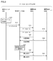
- FIG. 3 is a sequence diagram showing a data flow among the detection unit 200, the management server 300, and the portable terminals 400A and 400B.
- step S10 the detection unit 200 detects a nurse call from a patient.
- the nurse call is detected based on, for example, the patient pressing the call button 100 (see FIG. 2).
- step S12 the detection unit 200 transmits a nurse call to the management server 300.
- step S14 the management server 300 transmits a command for informing the nurse call to each of the mobile terminals 400A and 400B.
- step S20 the management server 300 acquires the current positions of the mobile terminals 400A and 400B from the mobile terminals 400A and 400B, respectively.
- the method for acquiring the current position is arbitrary.
- the mobile terminals 400A and 400B incorporate a GPS (Global Positioning System) signal receiver.
- the portable terminals 400A and 400B transmit the position information specified from the received GPS signal to the management server 300 as the current position.
- step S30 the management server 300, based on the current position received from each mobile terminal, the mobile terminal that has reached the area C1 (see FIG. 2) including the place where the nurse call is received from the mobile terminals 400A and 400B. Is detected.
- step S32 the management server 300 transmits a nurse call stop command to each of the mobile terminals 400A and 400B.
- Each of portable terminal 400A, 400B stops the alert
- the management server 300 identifies each location of the portable terminal 400 by a GPS signal. However, the management server 300 detects a nurse by an IC tag or biometric authentication, which will be described later, and owns the portable terminal owned by the nurse. It may be determined whether or not terminal 400 exists in a predetermined area (for example, area C1).
- FIG. 4 is a diagram illustrating an example of a functional configuration of the management server 300.
- the management server 300 includes a nurse call receiving unit 350, a notification command transmitting unit 352, a room specifying unit 354, a location information receiving unit 360, a terminal managing unit 362, as functional configurations.
- a room entry detection unit 370, a stop command transmission unit 375, and a history management unit 380 are provided. These functions are realized by the control device 301 (see FIG. 12) of the management server 300, for example.
- the nurse call receiving unit 350 receives a nurse call from the detection unit 200 when the detection unit 200 (see FIG. 2) detects the patient's nurse call.
- the notification command transmission unit 352 transmits a nurse call notification command to each of the mobile terminals 400 based on the reception of the nurse call from the detection unit 200 (see FIG. 2). Thereby, each of the portable terminals 400 notifies a nurse call.
- the room identification unit 354 identifies the room from which the nurse call is transmitted (hereinafter also referred to as “transmission room”). As an example, the call room for the nurse call is specified based on the detection unit information 322.
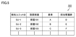
- FIG. 5 is a diagram showing the contents of the detection unit information 322.
- the detection unit information 322 includes identification information (for example, ID: Identification) of the detection unit 200, an installation room of the detection unit 200, a patient who is hospitalized in the installation room, and a nurse in charge of the patient. Are related to each other.
- the room specifying unit 354 receives the identification information of the detection unit from the detection unit that is the source of the nurse call, refers to the detection unit information 322, and transmits the nurse call to the installation room associated with the identification information. Identify as a room.
- the nurse call receiving unit 350 outputs room information for identifying the specified transmission room to the room entry detecting unit 370.
- the location information receiving unit 360 receives the current location of the mobile terminal from each of the mobile terminals 400 at regular intervals.
- the current position of the mobile terminal 400 is represented by a two-dimensional or three-dimensional coordinate value.
- the location information receiving unit 360 outputs the current location of each mobile terminal to the terminal management unit 362.
- the terminal management unit 362 writes each current position of the mobile terminal 400 in the mobile terminal information 324.
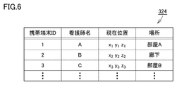
- FIG. 6 is a diagram showing the contents of the mobile terminal information 324.
- the terminal management unit 362 includes identification information (for example, ID) of the mobile terminal, the name of the nurse who owns the mobile terminal, the current position of the mobile terminal, and the name of the place indicated by the current position. Are written in the portable terminal information 324 in association with each other.
- the room entry detecting unit 370 refers to the room information 326 and detects the mobile terminal that has reached the area C1 (see FIG. 2) including the place where the nurse call is received.
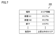
- FIG. 7 is a diagram showing the contents of the room information 326.
- the room information 326 associates a place name with area information indicating the position of the place.
- the area information is represented by, for example, the coordinate value of the end point of the rectangular area, the horizontal width of the rectangular area, and the width of the rectangular area.
- the room entry detection unit 370 refers to the room information 326 and acquires area information associated with the room identified by the room identification unit 354. Thereafter, the room entry detection unit 370 acquires the current position of each mobile terminal with reference to the mobile terminal information 324 in FIG. 6, and whether or not the current position of each mobile terminal is included in the area indicated by the acquired area information. Determine whether. When it is determined that the current position of each mobile terminal is included in the area, the room entry detection unit 370 determines that the nurse has entered the nurse call call room.
- the stop command transmission unit 375 transmits a nurse call notification stop command to at least a part of the portable terminal 400 when entry into the nurse call transmission room is detected.
- the nurse call stop command may be transmitted to all of the mobile terminals 400 or may be transmitted to a part of the mobile terminals 400.
- the history management unit 380 records the detection result of the patient's nurse call and the result of the nurse's response to the nurse call in the history information 328.
- FIG. 8 is a diagram showing the contents of the history information 328.
- the history information 328 includes nurse call detection unit identification information (for example, ID), a detection result of the detection unit, a detection time, a flag indicating whether the nurse call is being reported, A flag indicating whether or not the mobile terminal is compatible with identification information (for example, ID) of the mobile terminal.
- the detection result of the detection unit includes not only the reception of the nurse call but also the detected behavior of the patient (for example, behavior or getting out of bed).
- the flag indicating whether or not the nurse call is being notified is set to “1” during the notification of the nurse call, and is set to “0” when the nurse call is not notified.
- the flag indicating whether or not the nurse is responding is set to “1” when the nurse enters the nurse call transmission room, and “0” when the nurse leaves the nurse call transmission room. "Is set.
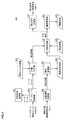
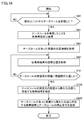
- FIG. 9 is a flowchart showing a part of processing executed by detection unit 200.
- the processing in FIG. 9 is realized by the control device 201 (see FIG. 12) of the detection unit 200 executing a program. In other aspects, some or all of the processing may be performed by circuit elements or other hardware.
- step S50 the control device 201 determines whether a nurse call has been detected.
- control device 201 determines that a nurse call has been detected (YES in step S50)
- control is switched to step S52. If not (NO in step S50), control device 201 executes step S50 again.
- step S52 the control device 201 transmits to the management server 300 that a nurse call has been detected.
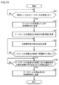
- FIG. 10 is a flowchart showing a part of processing executed by management server 300 according to the first embodiment.
- the processing in FIG. 10 is realized by the control device 301 (see FIG. 12) of the management server 300 executing the program. In other aspects, some or all of the processing may be performed by circuit elements or other hardware.
- step S60 the control device 301 determines whether the nurse call is received from the detection unit 200 as the nurse call receiving unit 350 (see FIG. 4). When control device 301 determines that a nurse call has been received from detection unit 200 (YES in step S60), control device 301 switches control to step S62. If not (NO in step S60), control device 301 executes step S60 again.
- step S62 the control device 301 transmits the reception of the nurse call from the detection unit 200 to each nurse's mobile terminal.
- step S64 the control device 301 refers to the detection unit information 322 (see FIG. 5) as the room identifying unit 354 (see FIG. 4), identifies the nurse call transmission room, and room information 326 (see FIG. 7). ) To obtain area information of the calling room. In the following, it is assumed that the range indicated by the identified area information is the area C1 (see FIG. 2).
- step S66 the control device 301 acquires the position information of the mobile terminal as the current position from each nurse's mobile terminal as the position information receiving unit 360 (see FIG. 4).
- step S70 the control device 301 determines whether any of the current positions of the mobile terminals is included in the area C1 (see FIG. 2) specified in step S64 as the room entry detection unit 370 (see FIG. 4). to decide.
- the control device 301 determines that the nurse has entered the nurse call room when any of the current positions of the mobile terminals is included in the area C1.
- control is switched to step S80. If not (NO in step S70), control device 301 returns control to step S66.
- step S80 the control device 301 transmits a nurse call notification stop command to at least a part of the portable terminal 400.
- the nurse call stop command may be transmitted to all of the mobile terminals 400 or may be transmitted to a part of the mobile terminals 400.
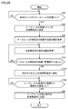
- FIG. 11 is a flowchart showing a part of processing executed by portable terminal 400.
- the processing in FIG. 11 is realized by the control device 401 (see FIG. 12) of the mobile terminal 400 executing the program. In other aspects, some or all of the processing may be performed by circuit elements or other hardware.
- step S90 the control device 401 determines whether a nurse call is received from the management server 300 or not.
- control device 401 determines that a nurse call has been received from management server 300 (YES in step S90)
- control device 401 switches control to step S92. If not (NO in step S90), control device 401 executes step S90 again.
- step S92 the control device 401 notifies a nurse call.
- the room number of the call room for the nurse call, the name of the patient who sent the nurse call, etc. may be notified.
- step S94 the control device 401 transmits the current position to the management server 300.
- the current position is transmitted at regular intervals, for example.
- step S100 the control device 401 determines whether a nurse call stop command has been received from the management server 300 or not.
- control device 401 determines that a nurse call stop command has been received from management server 300 (YES in step S100)
- control device 401 switches control to step S102. If not (NO in step S100), control device 401 returns control to step S94.
- step S102 the control device 401 stops the notification of the nurse call. More specifically, the control device 401 deletes the warning message from the display screen and returns to the normal screen, or stops outputting the warning sound.
- FIG. 12 is a block diagram illustrating a main hardware configuration of the nurse call system 500.
- the nurse call system 500 includes a detection unit 200, a management server 300, and a mobile terminal 400.
- the detection unit 200, the management server 300, and the portable terminal 400 are connected to each other via a network.
- the hardware configuration of the detection unit 200, the hardware configuration of the management server 300, and the hardware configuration of the mobile terminal 400 will be described in order.
- the detection unit 200 includes a control device 201, a ROM (Read Only Memory) 202, a RAM (Random Access Memory) 203, a network interface 204, a camera interface 205, a storage device 220, and the like. including.
- the control device 201 is configured by at least one integrated circuit, for example.
- the integrated circuit includes, for example, at least one CPU (Central Processing Unit), at least one ASIC (Application Specific Integrated Circuit), at least one FPGA (Field Programmable Gate Array), or a combination thereof.
- CPU Central Processing Unit
- ASIC Application Specific Integrated Circuit
- FPGA Field Programmable Gate Array
- the control device 201 controls the operation of the detection unit 200 by executing various programs such as the control program 222 according to the present embodiment.
- the control device 201 reads the control program 222 from the storage device 220 to the ROM 202 based on receiving the execution instruction of the control program 222.
- the RAM 203 functions as a working memory and temporarily stores various data necessary for executing the control program 222.
- the network interface 204 is connected to a communication device such as an antenna or a NIC (Network Interface Card).
- the detection unit 200 transmits / receives data to / from other communication terminals via the communication device.
- Other communication terminals include, for example, the management server 300, the portable terminal 400, and the like.
- the detection unit 200 may be configured so that the control program 222 can be downloaded from a server via a network.
- the camera interface 205 is an interface for connecting the camera 206 and the detection unit 200 in a wired or wireless manner.
- the detection unit 200 acquires an image from the camera 206 via the camera interface 205.
- the camera 206 includes, for example, a network camera or other imaging device capable of photographing a subject.
- the camera 206 may be configured integrally with the detection unit 200, or may be configured separately from the detection unit 200 as shown in FIG.
- the camera 206 is installed at the entrance of a hospital room, for example.
- the detection unit 200 detects a nurse who has entered a hospital room based on an image from the camera 206.
- Storage device 220 is a storage medium such as a hard disk or an external storage device. As an example, storage device 220 stores control program 222 according to the present embodiment.
- control program 222 may be provided by being incorporated in a part of an arbitrary program, not as a single program. In this case, processing according to the present embodiment is realized in cooperation with an arbitrary program. Even such a program that does not include some modules does not depart from the spirit of the detection unit 200 according to the present embodiment. Furthermore, part or all of the functions provided by control program 222 according to the present embodiment may be realized by dedicated hardware. Furthermore, a part or all of the functions provided by the control program 222 may be realized by the cooperation of the detection unit 200, the management server 300, and the portable terminal 400. Furthermore, the detection unit 200 may be configured in the form of a so-called cloud service in which at least one server realizes processing according to the present embodiment.
- the management server 300 includes a control device 301, a ROM 302, a RAM 303, a network interface 304, and a storage device 320.
- the control device 301 is configured by at least one integrated circuit, for example.
- the integrated circuit includes, for example, at least one CPU, at least one ASIC, at least one FPGA, or a combination thereof.
- the control device 301 controls the operation of the management server 300 by executing various programs such as the control program 329 according to the present embodiment.
- the control device 301 reads the control program 329 from the storage device 320 to the ROM 302 based on receiving the execution instruction of the control program 329.
- the RAM 303 functions as a working memory and temporarily stores various data necessary for executing the control program 329.
- the network interface 304 is connected to a communication device such as an antenna or a NIC.
- the management server 300 transmits / receives data to / from other communication terminals via the communication device.
- Other communication terminals include, for example, the detection unit 200, the portable terminal 400, and the like.
- the management server 300 may be configured to download the control program 329 from the server via a network.
- the storage device 320 is, for example, a storage medium such as a hard disk or an external storage device.
- the storage device 320 includes detection unit information 322 (see FIG. 5), portable terminal information 324 (see FIG. 6), room information 326 (see FIG. 7), history information 328 (see FIG. 8), and the present embodiment.
- a control program 329 and the like according to the form are stored.
- the storage location of the portable terminal information 324, the room information 326, the history information 328, and the control program 329 is not limited to the storage device 320.
- the storage area of the control device 301 for example, a cache
- ROM 302, RAM 303 or It may be stored in an external storage device or the like.
- control program 329 may be provided by being incorporated in a part of an arbitrary program, not as a single program. In this case, processing according to the present embodiment is realized in cooperation with an arbitrary program. Even such a program that does not include some modules does not depart from the spirit of the management server 300 according to the present embodiment. Furthermore, part or all of the functions provided by control program 329 according to the present embodiment may be realized by dedicated hardware. Furthermore, a part or all of the functions provided by the control program 329 may be realized by the cooperation of the detection unit 200, the management server 300, and the portable terminal 400. Furthermore, the management server 300 may be configured in the form of a so-called cloud service in which at least one server realizes processing according to the present embodiment.
- the mobile terminal 400 includes a control device 401, a ROM 402, a RAM 403, a network interface 404, a display unit 405, a GPS receiver 406, and a storage device 420.
- the control device 401 is constituted by at least one integrated circuit, for example.
- the integrated circuit includes, for example, at least one CPU, at least one ASIC, at least one FPGA, or a combination thereof.
- Control device 401 controls the operation of portable terminal 400 by executing various programs such as control program 422 according to the present embodiment.
- the control device 401 reads the control program 422 from the storage device 420 to the ROM 402 based on receiving the execution instruction of the control program 422.
- the RAM 403 functions as a working memory and temporarily stores various data necessary for executing the control program 422.
- the antenna etc. are connected to the network interface 404.
- the portable terminal 400 transmits / receives data to / from other communication terminals via the antenna.
- Other communication terminals include, for example, the detection unit 200, the management server 300, and the like.
- the portable terminal 400 may be configured to download the control program 422 from a server via a network.
- the display unit 405 displays a message indicating an emergency when a nurse call is accepted.
- the message includes the room number of the nurse caller, the name of the patient, and the like.
- the GPS receiver 406 receives a GPS signal via an antenna (not shown).
- the control device 401 identifies the current position of the mobile terminal 400 from the GPS signal.
- the storage device 420 is a storage medium such as eMMC (Embedded MultiMediaCard). As an example, storage device 420 stores control program 422 according to the present embodiment.
- eMMC embedded MultiMediaCard
- control program 422 may be provided by being incorporated in a part of an arbitrary program, not as a single program. In this case, processing according to the present embodiment is realized in cooperation with an arbitrary program. Even such a program that does not include some modules does not depart from the spirit of portable terminal 400 according to the present embodiment. Furthermore, part or all of the functions provided by control program 422 according to the present embodiment may be realized by dedicated hardware. Furthermore, a part or all of the functions provided by the control program 422 may be realized by the cooperation of the detection unit 200, the management server 300, and the portable terminal 400. Furthermore, the mobile terminal 400 may be configured in a form such as a so-called cloud service in which at least one server realizes processing according to the present embodiment.
- nurse call system 500 transmits a nurse call notification command to each mobile terminal when a nurse call is detected. Thereafter, based on the fact that the nurse has reached the nurse call transmission room, the nurse call system 500 transmits a nurse call notification stop command to each portable terminal.
- the nurse call system 500 notifies the nurse call to all nurses before the nurse hangs on the patient, and stops the nurse call notification after the nurse hangs on the patient. To do.
- the nurse call system 500 can prevent the nurse from rushing to the patient after making the nurse aware of the patient's nurse call.
- the nurse call system 500 specifies the nurse's mobile terminal corresponding to another room based on the nurse entering the nurse call transmission room. Then, a nurse call stop command is transmitted to the portable terminal.
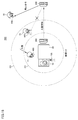
- FIG. 13 is a conceptual diagram schematically showing nurse call stop processing according to the second embodiment.
- the nurse call system 500 includes a detection unit 200, a management server 300, and a mobile terminal 400.
- the management server 300 receives a nurse call from the patient 10 from the detection unit 200, the management server 300 transmits a command for informing the nurse call to the portable terminals 400 of the nurses 11, 13, and 14. Thereby, each of the portable terminals 400 notifies a nurse call.
- the management server 300 receives the current position of the mobile terminal from each of the mobile terminals 400 after transmitting a nurse call notification command to the mobile terminal 400. Based on the current location of each mobile terminal 400, the management server 300 detects a mobile terminal that has reached the area C ⁇ b> 1 including the place where the nurse call originated from among the mobile terminals 400. In the example of FIG. 13, the portable terminal 400 of the nurse 11 is detected.
- the management server 300 When the management server 300 detects a mobile terminal that has reached the area C1, the management server 300 identifies a mobile terminal that exists in the area C2 different from the area C1 from the mobile terminals 400 based on the current position of each mobile terminal 400. To do. Area C2 is set as the range of the patient's 9 room. The management server 300 transmits a nurse call stop command to the portable terminal 400 of the nurse 13 in the area C2, and does not transmit a nurse call stop command to the nurse 14 not in the areas C1 and C2. In other words, the portable terminal 400 of the nurse 14 who is not in the hospital room remains informed of the nurse call.
- the mobile terminals that stop the notification of the nurse call include mobile terminals that exist in the area C2. Since the portable terminal 400 in the other room is stopped from the nurse call, the nurse 13 who is responding is not hindered from working. Further, since the nurse terminal that is not compatible with the portable terminal 400 does not stop the nurse call, the nurse 14 can assist the nurse 11 by placing it on the nurse 11.
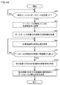
- FIG. 14 is a flowchart showing a part of processing executed by management server 300 according to the second embodiment.
- step 14 is realized by the control device 301 (see FIG. 12) of the management server 300 executing the program. In other aspects, some or all of the processing may be performed by circuit elements or other hardware. Since each process other than steps S72A and S80A is as described in FIG. 10, the description thereof will not be repeated.
- step S72A the control device 301 identifies the nurse's mobile terminal that is currently working in another room based on the nurse entering the nurse call room. More specifically, the control device 301 acquires area information of each room from the room information 326 (see FIG. 7), and refers to the mobile terminal information 324 (see FIG. 6) to determine the current position of each mobile terminal. get. The control device 301 determines for each mobile terminal whether or not the current position of the mobile terminal is included in the area of each room. The control device 301 identifies a mobile terminal included in the area of each room as a mobile terminal possessed by a nurse who is handling in another room.
- step S80A the control device 301 transmits a nurse call stop command to the portable terminal of the nurse who is handling in another room.
- the control device 301 does not transmit a nurse call stop command to the portable terminal of the non-supporting nurse.
- the nurse call system 500 is based on the fact that the nurse has entered the nurse call transmission room, and the portable terminal possessed by the nurse who is in another room. Stop the nurse call. Thereby, the nurse call system 500 can prevent obstructing the work of the nurse who is handling in another room.
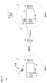
- FIG. 15 is a conceptual diagram schematically showing nurse call stop processing in the third embodiment.
- the nurse call system 500 includes a detection unit 200, a management server 300, and a mobile terminal 400.
- the management server 300 receives a nurse call from the patient 10 from the detection unit 200, the management server 300 transmits a command for notifying the nurse call to the mobile terminals 400 of the nurses 11, 15, and 16. Thereby, each portable terminal 400 notifies a nurse call.
- the management server 300 receives the current position of the mobile terminal from each of the mobile terminals 400 after transmitting a nurse call notification command to the mobile terminal 400. Based on the current location of each mobile terminal 400, the management server 300 detects the mobile terminal that has reached the area C ⁇ b> 1 including the place where the nurse call originated from the mobile terminal 400. In the example of FIG. 15, the portable terminal 400 of the nurse 11 is detected.
- the management server 300 When the management server 300 detects a mobile terminal that has reached the area C1, the management server 300 is an area outside the area C1 and surrounding the area C1 based on the current position of each mobile terminal 400. A mobile terminal existing in C3 (outer area) is specified. The management server 300 does not transmit a nurse call stop command to the portable terminal 400 of the nurse 15 in the area C3. That is, the portable terminal existing in the area C3 remains informed of the nurse call. The management server 300 transmits a nurse call stop command to the portable terminal 400 of the nurse 16 outside the area C3.
- mobile terminals that do not stop nurse call notification include mobile terminals that exist in area C3. Thereby, since the nurse call is not stopped for the nurse 15 in the vicinity of the nurse call transmission room, the nurse 15 can rush to the nurse 11 to assist the nurse 11.
- the management server 300 may stop informing the mobile terminals in order from the mobile terminals that are far from the area C1.
- the timing for stopping the notification of the nurse call is earlier for mobile terminals that are located away from the area C1, and is delayed for mobile terminals that are located near the area C1.
- FIG. 16 is a flowchart showing a part of processing executed by management server 300 according to the third embodiment.
- the processing in FIG. 16 is realized by the control device 301 (see FIG. 12) of the management server 300 executing the program. In other aspects, some or all of the processing may be performed by circuit elements or other hardware. Since the processes other than steps S72B and S80B are as described with reference to FIG. 10, their description will not be repeated.
- the control device 301 identifies a mobile terminal that is located away from the nurse call room. That is, the control device 301 specifies a mobile terminal that exists outside the area C3 (see FIG. 15). More specifically, the control device 301 acquires area information of the area C3 from the room information 326 (see FIG. 7), and refers to the mobile terminal information 324 (see FIG. 6) to determine the current position of each mobile terminal. get. The control device 301 determines for each mobile terminal whether or not the current position of the mobile terminal exists outside the area C3. The control device 301 identifies a mobile terminal that exists outside the area C3 as a mobile terminal that is located away from the nurse call call room.
- step S80B the control device 301 transmits a nurse call stop command to a mobile terminal existing outside the area C3.
- the control device 301 does not transmit a nurse call stop command to the mobile terminals existing in the area C3.
- the nurse call system 500 is based on the fact that the nurse has entered the nurse call transmission room, and the nurse call system for the mobile terminal that is located away from the call room. The call is stopped, and the nurse call is not stopped for the mobile terminals existing in the vicinity of the calling room. As a result, the nurse in the vicinity of the transmission room can be applied to the nurse being dealt with and can assist the nurse being dealt with.
- the nurse call system 500 does not stop the nurse call on the portable terminal of the nurse who is in charge of the patient who has issued the nurse call, and is not in charge of the patient who has made the nurse call. The nurse call is stopped for the nurse's mobile terminal.
- FIG. 17 is a conceptual diagram schematically showing nurse call stop processing in the fourth embodiment.
- the nurse call system 500 includes a detection unit 200, a management server 300, and a mobile terminal 400.
- the management server 300 receives a nurse call from the patient 10 from the detection unit 200, the management server 300 transmits a command for notifying the nurse call to the portable terminals 400 of the nurses 11, 17-19. Thereby, each portable terminal 400 notifies a nurse call.
- the management server 300 receives the current position of the mobile terminal from each of the mobile terminals 400 after transmitting a nurse call notification command to the mobile terminal 400. Based on the current location of each mobile terminal 400, the management server 300 detects the mobile terminal that has reached the area C ⁇ b> 1 including the place where the nurse call originated from the mobile terminal 400. In the example of FIG. 17, the portable terminal 400 of the nurse 11 is detected.
- the management server 300 identifies the mobile terminal of the person in charge of the patient 10 when detecting the mobile terminal that has reached the area C1. For example, the identification information of the portable terminal of the person in charge is associated in advance with the area C1. A nurse call stop command is not transmitted to the portable terminal identified by the identification information. That is, the management server 300 does not transmit a nurse call stop command to the portable terminal of the nurse 17 who is in charge of the patient 10. Thereby, the nurse call system 500 can make the nurse 17 who is the person in charge hang on the patient 10.
- the management server 300 transmits a nurse call stop command to the mobile terminals of the nurses 18 and 19 who are not in charge of the patient 10. Thereby, the management server 300 can prevent the nurses 18 and 19, who are not in charge, from being used unnecessarily on the patient 10.
- FIG. 18 is a flowchart showing a part of processing executed by management server 300 according to the fourth embodiment.
- step S72C the control device 301 identifies the portable terminal possessed by the nurse in charge of the nurse call transmission room. More specifically, the control device 301 refers to the detection unit information 322 (see FIG. 5), specifies the name of the nurse in charge associated with the detection unit that is the source of the nurse call, and the mobile terminal information The mobile terminal ID associated with the nurse name is specified with reference to 324 (see FIG. 6). The control device 301 specifies the mobile terminal identified by the ID as a mobile terminal owned by the nurse in charge.
- step S80C the control device 301 transmits a nurse call stop command to a portable terminal possessed by a nurse other than the nurse in charge. Thereby, the notification of the nurse call in the non-person-in-charge portable terminal is stopped.
- the nurse call system 500 notifies the nurse call of the mobile terminal of the person in charge of the call room based on the fact that the nurse has entered the call room of the nurse call.
- the nurse call notification is stopped for the portable terminal of the non-in-charge nurse in the transmission room.
- the nurse call system 500 can cause the nurse in charge to be placed on the patient and reduce the burden on the non-care nurse.
- the timing for transmitting the nurse call stop command is not particularly limited.
- nurse call system 500 according to the fifth embodiment is configured to stop nurse call after a predetermined time has elapsed since it was detected that a nurse entered the nurse call transmission room. To each mobile device. That is, the nurse call stop command is transmitted when the stay time in the area C1 of the mobile terminal that has reached the area C1 exceeds a predetermined time. As a result, the nurse call system 500 can prevent the nurse call from being stopped in a state where the patient is not supported, such as when the nurse has passed the nurse call transmission room.
- FIG. 19 is a flowchart showing a part of processing executed by management server 300 according to the fifth embodiment.
- step S72D is realized by the control device 301 (see FIG. 12) of the management server 300 executing the program. In other aspects, some or all of the processing may be performed by circuit elements or other hardware. Since each process other than step S72D is as described in FIG. 10, the description thereof will not be repeated.
- step S72D the control device 301 determines whether or not the stay time of the mobile terminal in the nurse call call room has exceeded a predetermined time. More specifically, the control device 301 starts counting time based on detection of a nurse who has entered the transmission room in step S70. As an example, the control device 301 counts time using the timer function of the control device 301. The control device 301 determines that the stay time of the mobile terminal in the nurse call call room has exceeded a predetermined time when a predetermined time has elapsed since the start of time counting. If control device 301 determines that the stay time of the mobile terminal in the nurse call call room has exceeded a predetermined time (YES in step S72D), control is switched to step S80. If not (NO in step S72D), control device 301 executes step S72D again.
- nurse call system 500 issues a nurse call stop instruction after a predetermined time has elapsed since it was detected that a nurse entered the nurse call transmission room. Send to each mobile device.
- the nurse call system 500 can prevent the nurse call from being stopped in a state where the patient is not supported, such as when the nurse has passed the nurse call transmission room.
- the nurse call system 500 according to the first embodiment transmits a nurse call stop command to each mobile terminal based on the fact that the nurse has reached the nurse call transmission room.
- the nurse call system 500 according to the sixth embodiment transmits a nurse call stop command to each mobile terminal based on the fact that the nurse has left the nurse call transmission room.
- FIG. 20 is a flowchart showing a part of processing executed by management server 300 according to the sixth embodiment.
- step S72E the control device 301 causes each mobile terminal to display a message indicating that the nurse is responding based on the fact that the nurse has reached the nurse call room.
- the content of the message includes the name of the nurse who is responding, the name of the patient, and the like.
- step S74E the control device 301 monitors the current position of the mobile terminal existing in the nurse call transmission room, and determines whether the corresponding nurse has left the transmission room.
- the control device 301 transmits a nurse call stop command to each portable terminal when it is determined that the corresponding nurse has left the call room.
- Each portable terminal displays a message indicating that it has been handled based on the receipt of the stop command. If control nurse 301 determines that the corresponding nurse has left the transmission room (YES in step S74E), control device 301 switches control to step S80. If not (NO in step S74E), control device 301 executes step S74E again.
- nurse call system 500 transmits a nurse call stop command to each mobile terminal based on the fact that the nurse has left the nurse call transmission room. As a result, other nurses do not have to rush to the patient who has already been treated.
- Nurse call system 500 detects a nurse who has entered the nurse call transmission room based on the current position of the nurse's mobile terminal.
- the nurse call system 500 according to the seventh embodiment detects a nurse who has entered the nurse call transmission room using a plurality of detection means.
- the nurse call system 500 detects a nurse who enters the nurse call transmission room using an IC (Integrated Circuit) tag. More specifically, each nurse has an IC tag in advance. An IC tag reader is installed in each hospital room. Preferably, the reading device is installed in the vicinity of the call button 100 (see FIG. 1). The nurse call system 500 detects the entry of the nurse based on the detection of the IC tag by the reading device.
- IC Integrated Circuit
- the nurse call system 500 detects the entry of the nurse call to the calling room by biometric authentication.
- Biometric authentication includes, for example, image authentication. More specifically, a camera 206 (see FIG. 12) is installed at the entrance of the hospital room. The nurse call system 500 uses an image processing technique such as face authentication to determine whether or not the person shown in the image is a nurse. When the nurse call system 500 determines that the person shown in the image is a nurse, the nurse call system 500 detects the entry of the nurse.
- the nurse call system 500 detects a nurse's entry into a room in combination with other detection information (for example, a patient's getting up, a patient's getting out of bed, a patient's falling or falling motion detection sensor).
- other detection information for example, a patient's getting up, a patient's getting out of bed, a patient's falling or falling motion detection sensor.
- nurse call system 500 detects a mobile terminal that has reached area C1 (see FIG. 2), which is a nurse call transmission room, using a plurality of different detection means.
- the nurse call system 500 transmits a nurse call stop command to each mobile terminal when all of the plurality of detection means detect the mobile terminal that has reached the area C1.
- the nurse call system 500 can more reliably detect that the nurse has entered the nurse call transmission room.
- the nurse call system includes an information terminal for receiving a nurse call and a plurality of portable terminals connected to the information terminal via a network.
- the information terminal receives the nurse call
- the information terminal transmits an instruction for notifying each of the plurality of mobile terminals of the nurse call to each of the plurality of mobile terminals.
- the mobile terminal that has reached the first area including the place where the nurse call is received is detected and the mobile terminal that has reached the first area is detected, the mobile terminals of at least some of the plurality of mobile terminals are detected.
- a command for stopping the notification of the nurse call is transmitted to the terminal.
- the information terminal receives a current position of the mobile terminal from each of the plurality of mobile terminals, and based on the current position of each of the plurality of mobile terminals, the information terminal A mobile terminal that has reached one area is detected.
- the information terminal specifies a mobile terminal existing in a second area different from the first area from the plurality of mobile terminals based on the current positions of the plurality of mobile terminals.
- the portable terminal that stops the notification of the nurse call includes the portable terminal that exists in the second area.
- the information terminal is located in an area outside the first area and surrounding the first area, out of the plurality of portable terminals, based on a current position of each of the plurality of portable terminals. Identify existing mobile devices.
- the portable terminal that does not stop the notification of the nurse call includes the portable terminal that exists in the outer area.
- the information terminal stores identification information of a mobile terminal associated with the first area.
- the portable terminal that does not stop the notification of the nurse call includes a portable terminal identified by the identification information among the plurality of portable terminals.
- the command for stopping the notification of the nurse call is transmitted when a stay time in the first area of the mobile terminal that has reached the first area exceeds a predetermined time.
- the information terminal detects the mobile terminal that has reached the first area with a plurality of different detection means.
- the command for stopping the notification of the nurse call is transmitted when all of the plurality of detection means detect a mobile terminal that has reached the first area.
Landscapes
- Engineering & Computer Science (AREA)
- Signal Processing (AREA)
- Health & Medical Sciences (AREA)
- Nursing (AREA)
- Life Sciences & Earth Sciences (AREA)
- Animal Behavior & Ethology (AREA)
- General Health & Medical Sciences (AREA)
- Public Health (AREA)
- Veterinary Medicine (AREA)
- Accommodation For Nursing Or Treatment Tables (AREA)
- Interconnected Communication Systems, Intercoms, And Interphones (AREA)
Abstract
患者のナースコールを看護師に報知した上で看護師の負担を減らすことができるナースコールシステムを提供する。ナースコールシステム(500)の管理サーバー(300)は、ナースコールを受信した場合に、複数の携帯端末(400)のそれぞれにナースコールを報知させるための命令を複数の携帯端末(400)のそれぞれに送信し、複数の携帯端末(400)の中から、ナースコールを受け付けた場所を含むエリア(C1)に到達した携帯端末(400)を検知し、エリア(C1)に到達した携帯端末(400)が検知された場合に、複数の携帯端末(400)の少なくとも一部の携帯端末にナースコールの報知を停止するための命令を送信する、ナースコールシステム。
Description
本開示は、ナースコールシステムの制御に関し、特に、患者からのナースコールを看護師に報知することが可能なナースコールシステムの制御に関する。
患者や介護者を見守るためのナースコールシステムが普及している。ナースコールシステムは、たとえば病院や介護施設などに設置される。ナースコールシステムは、患者からのナースコールを検知した場合に、ナースコールを各看護師の携帯端末に送信する。各携帯端末は、ナースコールを受信すると、患者が緊急事態にあることを看護師に報知する。これにより、各看護師は、患者の危険を逸早く察知でき、患者の元に素早く駆け付けることができる。
このようなナースコールシステムに関し、特開2007-268020号公報(特許文献1)は、「手が放せない看護業務に従事中の看護師に対しては、携帯端末の呼び出しを一時中止または呼び出しの優先順位を下げて従事中の看護業務を継続可能とし、看護業務の集中処理による効率化を達成することのできる」ナースコールシステムを開示している。特開2008-113679号公報(特許文献2)は、「患者からの呼び出しに対して近くに居る看護師の携帯端末に呼出通知がなされる」ナースコールシステムを開示している。特開2014-204751号公報(特許文献3)は、「患者からのナースコールに対し、最寄りの看護師に、自らが該ナースコールに対応すべき看護師であることを認識させる」ナースコールシステムを開示している。
ところで、患者からのナースコールが全ての看護師に通知されると、看護師の負担が増えてしまう。一方で、ナースコールが通知される看護師が減ると、患者への対応が遅れてしまう可能性がある。そのため、患者のナースコールを看護師に報知した上で看護師の負担を減らすことが可能なナースコールシステムが望まれている。
特許文献1に開示されるナースコールシステムは、ナースコールの発信元の病室とは異なる病室に居る看護師を検知し、当該看護師の携帯端末にはナースコールを送らない。すなわち、他の病室に居る看護師は、ナースコールに気付くことができない。このように、ナースコールが通知される看護師が減ってしまうと、患者の元に素早く駆け付けることができない可能性がある。
特許文献2,3に開示されるナースコールシステムは、患者からのナースコールに対して近くに居る看護師のみにナースコールを通知する。すなわち、当該ナースコールシステムは、患者からのナースコールに対して遠くに居る看護師にはナースコールを通知しない。このように、ナースコールが通知される看護師が減ってしまうと、患者の元に素早く駆け付けることができない可能性がある。
本開示は上述のような問題点を解決するためになされたものであって、ある局面における目的は、患者のナースコールを看護師に報知した上で看護師の負担を減らすことが可能なナースコールシステムを提供することである。他の局面における目的は、患者のナースコールを看護師に報知した上で看護師の負担を減らすことが可能な情報端末を提供することである。さらに他の局面における目的は、患者のナースコールを看護師に報知した上で看護師の負担を減らすことが可能な情報端末の制御方法を提供することである。さらに他の局面における目的は、患者のナースコールを看護師に報知した上で看護師の負担を減らすことが可能な情報端末の制御プログラムを提供することである。
ある局面に従うと、ナースコールシステムは、ナースコールを受信するための情報端末と、上記情報端末にネットワーク接続されている複数の携帯端末とを備える。上記情報端末は、上記ナースコールを受信した場合に、上記複数の携帯端末のそれぞれに上記ナースコールを報知させるための命令を上記複数の携帯端末のそれぞれに送信し、上記複数の携帯端末の中から、上記ナースコールを受け付けた場所を含む第1エリアに到達した携帯端末を検知し、上記第1エリアに到達した携帯端末が検知された場合に、上記複数の携帯端末の少なくとも一部の携帯端末に上記ナースコールの報知を停止するための命令を送信する。
他の局面に従うと、複数の携帯端末と通信することが可能な情報端末は、ナースコールを受信するためのナースコール受信部と、上記ナースコールを受信した場合に、上記複数の携帯端末のそれぞれに上記ナースコールを報知させるための命令を上記複数の携帯端末のそれぞれに報知させるための報知命令送信部と、上記複数の携帯端末の中から、上記ナースコールを受け付けた場所を含む第1エリアに到達した携帯端末を検知するための検知部と、上記第1エリアに到達した携帯端末が検知された場合に、上記複数の携帯端末の少なくとも一部の携帯端末に上記ナースコールの報知を停止するための命令を送信するための停止命令送信部とを備える。
さらに他の局面に従うと、複数の携帯端末と通信することが可能な情報端末の制御方法は、ナースコールを受信するステップと、上記ナースコールを受信した場合に、上記複数の携帯端末のそれぞれに上記ナースコールを報知させるための命令を上記複数の携帯端末のそれぞれに送信するステップと、上記複数の携帯端末の中から、上記ナースコールを受け付けた場所を含む第1エリアに到達した携帯端末を検知するステップと、上記第1エリアに到達した携帯端末が検知された場合に、上記複数の携帯端末の少なくとも一部の携帯端末に上記ナースコールの報知を停止するための命令を送信するステップとを備える。
さらに他の局面に従うと、複数の携帯端末と通信することが可能な情報端末の制御プログラムは、上記情報端末に、ナースコールを受信するステップと、上記ナースコールを受信した場合に、上記複数の携帯端末のそれぞれに上記ナースコールを報知させるための命令を上記複数の携帯端末のそれぞれに送信するステップと、上記複数の携帯端末の中から、上記ナースコールを受け付けた場所を含む第1エリアに到達した携帯端末を検知するステップと、上記第1エリアに到達した携帯端末が検知された場合に、上記複数の携帯端末の少なくとも一部の携帯端末に上記ナースコールの報知を停止するための命令を送信するステップとを実行させる。
ある局面において、患者のナースコールを看護師に報知した上で看護師の負担を減らすことができる。
本発明の上記および他の目的、特徴、局面および利点は、添付の図面と関連して理解される本発明に関する次の詳細な説明から明らかとなるであろう。
以下、図面を参照しつつ、本発明に従う各実施の形態について説明する。以下の説明では、同一の部品および構成要素には同一の符号を付してある。それらの名称および機能も同じである。したがって、これらについての詳細な説明は繰り返さない。なお、以下で説明される各実施の形態および各変形例は、適宜選択的に組み合わされてもよい。
<第1の実施の形態>
[ナースコールシステム500の装置構成]
図1を参照して、ナースコールシステム500のシステム構成について説明する。図1は、ナースコールシステム500のシステム構成の一例を示す図である。
[ナースコールシステム500の装置構成]
図1を参照して、ナースコールシステム500のシステム構成について説明する。図1は、ナースコールシステム500のシステム構成の一例を示す図である。
ナースコールシステム500は、たとえば、病院や介護施設などに設置される。図1に示されるように、ナースコールシステム500は、検知ユニット200と、情報端末としての管理サーバー300と、携帯端末400とを備える。検知ユニット200および管理サーバー300は、互いにネットワーク接続されている。管理サーバー300および携帯端末400は、互いにネットワーク接続されている。
検知ユニット200にはコールボタン100が接続されている。コールボタン100および検知ユニット200は、有線で接続されていてもよいし、無線で接続されていてもよい。コールボタン100は、たとえばベッド20の付近に設置されている。患者10は、自身が危険な状態にあるときや何らかの介助を要するときにコールボタン100を押す。検知ユニット200は、コールボタン100の押下をナースコールとして検知する。
ナースコールが検知ユニット200によって検知された場合に、管理サーバー300は、ナースコールを報知させるための命令を基地局を介して携帯端末400のそれぞれに送信する。管理サーバー300と携帯端末400との通信は、たとえばWiFi(Wireless Fidelity)により実現される。携帯端末400は、ナースコールの報知命令を管理サーバー300から受信すると、患者10が危険状態にあることを看護師11に報知する。報知方法の一例として、携帯端末400は、患者10が危険状態にあることを示す警告をメッセージとして表示したり、当該警告を音声で発したりする。これにより、看護師11は、患者10の危険に逸早く気付くことができ、患者10の元に素早く駆け付けることができる。
なお、図1には、コールボタン100が押しボタン式である例が示されているが、コールボタン100は、握りボタン式であってもよい。また、図1には、ナースコールシステム500が1つの検知ユニット200で構成されている例が示されているが、ナースコールシステム500は、複数の検知ユニット200で構成されてもよい。また、図1には、ナースコールシステム500が1つの管理サーバー300で構成されている例が示されているが、ナースコールシステム500は、複数の管理サーバー300で構成されてもよい。また、図1には、コールボタン100と検知ユニット200とが別個の装置として構成されているが、コールボタン100と検知ユニット200とは一体的に構成されてもよい。
[ナースコールの停止処理]
図2を参照して、ナースコールシステム500によるナースコールの停止処理について説明する。図2は、ナースコールの停止処理を概略的に示す概念図である。
図2を参照して、ナースコールシステム500によるナースコールの停止処理について説明する。図2は、ナースコールの停止処理を概略的に示す概念図である。
上述したように、ナースコールシステム500は、検知ユニット200と、管理サーバー300と、携帯端末400とを備える。管理サーバー300は、患者10からのナースコールを検知ユニット200から受信すると、ナースコールを報知させるための命令を看護師11,12の各携帯端末400に送信する。
管理サーバー300は、携帯端末400に対してナースコールの報知命令を送信した後に、携帯端末400の各々から当該携帯端末の現在位置を受信する。管理サーバー300は、携帯端末400の各々の現在位置に基づいて、携帯端末400の中から、ナースコールを受け付けた場所を含むエリアC1に到達した携帯端末を検知する。エリアC1の範囲は、管理サーバー300の管理者などによって予め設定されている。エリアC1の範囲は、たとえばナースコールを受け付けるコールボタン100の設置場所を基準として設定される。図2の例では、エリアC1は、患者10の病室の範囲として設定されている。管理サーバー300は、携帯端末400の各々から現在位置を一定時間ごとに取得し、現在位置の各々がエリアC1に含まれるか否かを判断する。管理サーバー300は、携帯端末400の現在位置のいずれかがエリアC1に含まれた場合に、看護師が患者10の元に到達したことを検知する。
管理サーバー300は、エリアC1に到達した携帯端末を検知した場合に、携帯端末400の少なくとも一部にナースコールの報知を停止するための命令を送信する。ナースコールの停止命令は、携帯端末400の全てに送信されてもよいし、携帯端末400の一部に送信されてもよい。
このように、ナースコールシステム500は、患者10からのナースコールを看護師11,12に報知し、看護師11が患者10の元に掛け付けた後には看護師11,12に対するナースコールの報知を停止する。これにより、ナースコールシステム500は、患者10のナースコールを看護師11,12に気付かせた上で、看護師12が患者10の元に無駄に駆け付けることを防止するこができる。
[ナースコールシステム500のデータフロー]
図3を参照して、ナースコールシステム500におけるデータの流れについて説明する。図3は、検知ユニット200と管理サーバー300と携帯端末400A,400Bとの間のデータの流れを示すシーケンス図である。
図3を参照して、ナースコールシステム500におけるデータの流れについて説明する。図3は、検知ユニット200と管理サーバー300と携帯端末400A,400Bとの間のデータの流れを示すシーケンス図である。
ステップS10において、検知ユニット200は、患者からナースコールを検知したとする。当該ナースコールは、たとえば患者がコールボタン100(図2参照)を押したことに基づいて検知される。
ステップS12において、検知ユニット200は、ナースコールを管理サーバー300に送信する。
ステップS14において、管理サーバー300は、携帯端末400A,400Bのそれぞれに、ナースコールを報知させるための命令を送信する。これにより、携帯端末400A,400Bは、患者のナースコールを看護師に報知する。
ステップS20において、管理サーバー300は、携帯端末400A,400Bのそれぞれから、携帯端末400A,400Bのそれぞれの現在位置を取得する。現在位置の取得方法は任意である。ある局面において、携帯端末400A,400Bには、GPS(Global Positioning System)信号の受信器が内蔵される。携帯端末400A,400Bは、受信したGPS信号から特定された位置情報を現在位置として管理サーバー300に送信する。
ステップS30において、管理サーバー300は、各携帯端末から受信した現在位置に基づいて、携帯端末400A,400Bの中から、ナースコールを受け付けた場所を含むエリアC1(図2参照)に到達した携帯端末を検知する。
ステップS32において、管理サーバー300は、携帯端末400A,400Bのそれぞれにナースコールの停止命令を送信する。携帯端末400A,400Bのそれぞれは、当該停止命令を受信したことに基づいてナースコールの報知を停止する。
上述の例では、管理サーバー300は、携帯端末400の各々の場所をGPS信号により特定しているが、後述するICタグや生体認証によって看護師を検出し、当該看護師が所有している携帯端末400が所定エリア(たとえば、エリアC1)に存在するか否かを判断してもよい。
[管理サーバー300の機能構成]
図4~図8を参照して、ナースコールシステム500を構成する管理サーバー300の機能について説明する。図4は、管理サーバー300の機能構成の一例を示す図である。図4に示されるように、管理サーバー300は、機能構成として、ナースコール受信部350と、報知命令送信部352と、部屋特定部354と、位置情報受信部360と、端末管理部362と、入室検知部370と、停止命令送信部375と、履歴管理部380とを備える。これらの機能は、たとえば管理サーバー300の制御装置301(図12参照)によって実現される。
図4~図8を参照して、ナースコールシステム500を構成する管理サーバー300の機能について説明する。図4は、管理サーバー300の機能構成の一例を示す図である。図4に示されるように、管理サーバー300は、機能構成として、ナースコール受信部350と、報知命令送信部352と、部屋特定部354と、位置情報受信部360と、端末管理部362と、入室検知部370と、停止命令送信部375と、履歴管理部380とを備える。これらの機能は、たとえば管理サーバー300の制御装置301(図12参照)によって実現される。
ナースコール受信部350は、検知ユニット200(図2参照)が患者のナースコールを検知した場合に、当該検知ユニット200からナースコールを受信する。
報知命令送信部352は、検知ユニット200(図2参照)からナースコールを受け付けたことに基づいて、ナースコールの報知命令を携帯端末400の各々に送信する。これにより、携帯端末400の各々は、ナースコールを報知する。
部屋特定部354は、ナースコールの発信元の部屋(以下、「発信部屋」ともいう。)を特定する。一例として、ナースコールの発信部屋は、検知ユニット情報322に基づいて特定される。図5は、検知ユニット情報322の内容を示す図である。一例として、検知ユニット情報322は、検知ユニット200の識別情報(たとえば、ID:Identification)と、検知ユニット200の設置部屋と、当該設置部屋に入院している患者と、当該患者の担当看護師とを互いに関連付けている。
部屋特定部354は、ナースコールの発信元の検知ユニットから当該検知ユニットの識別情報を受信し、検知ユニット情報322を参照して、当該識別情報に対応付けられている設置部屋をナースコールの発信部屋として特定する。ナースコール受信部350は、特定した発信部屋を識別するための部屋情報を入室検知部370に出力する。
位置情報受信部360は、携帯端末400の各々から当該携帯端末の現在位置を一定時間ごとに受信する。一例として、携帯端末400の現在位置は、2次元または3次元の座標値で表わされる。位置情報受信部360は、各携帯端末の現在位置を端末管理部362に出力する。
端末管理部362は、携帯端末400の各々の現在位置を携帯端末情報324に書き込む。図6は、携帯端末情報324の内容を示す図である。一例として、端末管理部362は、携帯端末の識別情報(たとえば、ID)と、当該携帯端末を所持する看護師の名前と、当該携帯端末の現在位置と、当該現在位置が示す場所の名前とを関連付けて携帯端末情報324に書き込む。
入室検知部370は、部屋情報326を参照して、ナースコールを受け付けた場所を含むエリアC1(図2参照)に到達した携帯端末を検知する。図7は、部屋情報326の内容を示す図である。部屋情報326は、場所の名前と当該場所の位置を表わすエリア情報とを互いに関連付けている。エリア情報は、たとえば、矩形領域の端点の座標値と、矩形領域の横幅と、矩形領域の楯幅とで表わされる。
より具体的には、入室検知部370は、部屋情報326を参照して、部屋特定部354によって特定された部屋に対応付けられているエリア情報を取得する。その後、入室検知部370は、図6の携帯端末情報324を参照して各携帯端末の現在位置を取得し、各携帯端末の現在位置が取得されたエリア情報によって示されるエリアに含まれるか否かを判断する。入室検知部370は、各携帯端末の現在位置が当該エリアに含まれると判断した場合、看護師がナースコールの発信部屋に入室したと判断する。
停止命令送信部375は、ナースコールの発信部屋への入室が検知された場合に、ナースコールの報知の停止命令を携帯端末400の少なくとも一部に送信する。ナースコールの停止命令は、携帯端末400の全てに送信されてもよいし、携帯端末400の一部に送信されてもよい。
履歴管理部380は、患者のナースコールの検知結果や当該ナースコールに対する看護師の対応結果を履歴情報328に記録する。図8は、履歴情報328の内容を示す図である。履歴情報328は、ナースコールの検知ユニットの識別情報(たとえば、ID)と、検知ユニットの検知結果と、検知時刻と、ナースコールを報知中であるか否かを示すフラグと、看護師が患者に対応しているか否かを示すフラグと、携帯端末の識別情報(たとえば、ID)とを互いに関連付けている。
好ましくは、検知ユニットの検知結果には、ナースコールを受け付けたことだけでなく、検知された患者の行動(たとえば、行動や離床など)が書き込まれる。ナースコールの報知中であるか否かを示すフラグは、ナースコールの報知中に「1」に設定され、ナースコールを報知していないときに「0」に設定される。看護師が対応中であるか否かを示すフラグは、ナースコールの発信部屋に看護師が入室した場合に「1」に設定され、ナースコールの発信部屋から看護師が退室した場合に「0」に設定される。
[検知ユニット200の制御構造]
図9を参照して、図2に示される検知ユニット200の制御構造について説明する。図9は、検知ユニット200が実行する処理の一部を表わすフローチャートである。図9の処理は、検知ユニット200の制御装置201(図12参照)がプログラムを実行することにより実現される。他の局面において、処理の一部または全部が、回路素子またはその他のハードウェアによって実行されてもよい。
図9を参照して、図2に示される検知ユニット200の制御構造について説明する。図9は、検知ユニット200が実行する処理の一部を表わすフローチャートである。図9の処理は、検知ユニット200の制御装置201(図12参照)がプログラムを実行することにより実現される。他の局面において、処理の一部または全部が、回路素子またはその他のハードウェアによって実行されてもよい。
ステップS50において、制御装置201は、ナースコールを検知したか否かを判断する。ステップS50において、制御装置201は、ナースコールを検知したと判断した場合(ステップS50においてYES)、制御をステップS52に切り替える。そうでない場合には(ステップS50においてNO)、制御装置201は、ステップS50の処理を再び実行する。
ステップS52において、制御装置201は、ナースコールを検知したことを管理サーバー300に送信する。
[管理サーバー300の制御構造]
図10を参照して、図2に示される管理サーバー300の制御構造について説明する。図10は、第1の実施の形態に従う管理サーバー300が実行する処理の一部を表わすフローチャートである。図10の処理は、管理サーバー300の制御装置301(図12参照)がプログラムを実行することにより実現される。他の局面において、処理の一部または全部が、回路素子またはその他のハードウェアによって実行されてもよい。
図10を参照して、図2に示される管理サーバー300の制御構造について説明する。図10は、第1の実施の形態に従う管理サーバー300が実行する処理の一部を表わすフローチャートである。図10の処理は、管理サーバー300の制御装置301(図12参照)がプログラムを実行することにより実現される。他の局面において、処理の一部または全部が、回路素子またはその他のハードウェアによって実行されてもよい。
ステップS60において、制御装置301は、ナースコール受信部350(図4参照)として、検知ユニット200からナースコールを受信したか否かを判断する。制御装置301は、検知ユニット200からナースコールを受信したと判断した場合(ステップS60においてYES)、制御をステップS62に切り替える。そうでない場合には(ステップS60においてNO)、制御装置301は、ステップS60の処理を再び実行する。
ステップS62において、制御装置301は、検知ユニット200からナースコールを受信したことを各看護師の携帯端末に送信する。
ステップS64において、制御装置301は、部屋特定部354(図4参照)として、検知ユニット情報322(図5参照)を参照してナースコールの発信部屋を特定するとともに、部屋情報326(図7参照)を参照して当該発信部屋のエリア情報を取得する。以下では、特定されたエリア情報が示す範囲は、エリアC1(図2参照)であったとする。
ステップS66において、制御装置301は、位置情報受信部360(図4参照)として、各看護師の携帯端末から当該携帯端末の位置情報を現在位置として取得する。
ステップS70において、制御装置301は、入室検知部370(図4参照)として、各携帯端末の現在位置のいずれかがステップS64で特定されたエリアC1(図2参照)に含まれたか否かを判断する。制御装置301は、各携帯端末の現在位置のいずれかがエリアC1に含まれる場合に、看護師がナースコールの発信部屋に入室したと判断する。制御装置301は、各携帯端末の現在位置のいずれかがエリアC1内に到達したと判断した場合(ステップS70においてYES)、制御をステップS80に切り替える。そうでない場合には(ステップS70においてNO)、制御装置301は、制御をステップS66に戻す。
ステップS80において、制御装置301は、携帯端末400の少なくとも一部にナースコールの報知の停止命令を送信する。ナースコールの停止命令は、携帯端末400の全てに送信されてもよいし、携帯端末400の一部に送信されてもよい。
[携帯端末400の制御構造]
図11を参照して、図2に示される携帯端末400の制御構造について説明する。図11は、携帯端末400が実行する処理の一部を表わすフローチャートである。図11の処理は、携帯端末400の制御装置401(図12参照)がプログラムを実行することにより実現される。他の局面において、処理の一部または全部が、回路素子またはその他のハードウェアによって実行されてもよい。
図11を参照して、図2に示される携帯端末400の制御構造について説明する。図11は、携帯端末400が実行する処理の一部を表わすフローチャートである。図11の処理は、携帯端末400の制御装置401(図12参照)がプログラムを実行することにより実現される。他の局面において、処理の一部または全部が、回路素子またはその他のハードウェアによって実行されてもよい。
ステップS90において、制御装置401は、管理サーバー300からナースコールを受信したか否かを判断する。制御装置401は、管理サーバー300からナースコールを受信したと判断した場合(ステップS90においてYES)、制御をステップS92に切り替える。そうでない場合には(ステップS90においてNO)、制御装置401は、ステップS90の処理を再び実行する。
ステップS92において、制御装置401は、ナースコールを報知する。同時に、ナースコールの発信部屋の部屋番号やナースコールの発信元の患者の名前などが報知されてもよい。
ステップS94において、制御装置401は、現在位置を管理サーバー300に送信する。当該現在位置は、たとえば一定時間ごとに送信される。
ステップS100において、制御装置401は、管理サーバー300からナースコールの停止命令を受信したか否かを判断する。制御装置401は、管理サーバー300からナースコールの停止命令を受信したと判断した場合(ステップS100においてYES)、制御をステップS102に切り替える。そうでない場合には(ステップS100においてNO)、制御装置401は、制御をステップS94に戻す。
ステップS102において、制御装置401は、ナースコールの報知を停止する。より具体的には、制御装置401は、警告メッセージを表示画面から消去して通常画面に戻したり、警告音声の出力を停止したりする。
[ナースコールシステム500のハードウェア構成]
図12を参照して、ナースコールシステム500のハードウェア構成の一例について説明する。図12は、ナースコールシステム500の主要なハードウェア構成を示すブロック図である。
図12を参照して、ナースコールシステム500のハードウェア構成の一例について説明する。図12は、ナースコールシステム500の主要なハードウェア構成を示すブロック図である。
図12に示されるように、ナースコールシステム500は、検知ユニット200と、管理サーバー300と、携帯端末400とを含む。検知ユニット200と管理サーバー300と携帯端末400とは、互いにネットワーク接続されている。以下では、検知ユニット200のハードウェア構成と、管理サーバー300のハードウェア構成と、携帯端末400のハードウェア構成とについて順に説明する。
(検知ユニット200のハードウェア構成)
図12に示されるように、検知ユニット200は、制御装置201と、ROM(Read Only Memory)202と、RAM(Random Access Memory)203と、ネットワークインターフェイス204と、カメラインターフェイス205と、記憶装置220とを含む。
図12に示されるように、検知ユニット200は、制御装置201と、ROM(Read Only Memory)202と、RAM(Random Access Memory)203と、ネットワークインターフェイス204と、カメラインターフェイス205と、記憶装置220とを含む。
制御装置201は、たとえば、少なくとも1つの集積回路によって構成される。集積回路は、たとえば、少なくとも1つのCPU(Central Processing Unit)、少なくとも1つのASIC(Application Specific Integrated Circuit)、少なくとも1つのFPGA(Field Programmable Gate Array)、またはそれらの組み合わせなどによって構成される。
制御装置201は、本実施の形態に従う制御プログラム222などの各種プログラムを実行することで検知ユニット200の動作を制御する。制御装置201は、制御プログラム222の実行命令を受け付けたことに基づいて、制御プログラム222を記憶装置220からROM202に読み出す。RAM203は、ワーキングメモリとして機能し、制御プログラム222の実行に必要な各種データを一時的に格納する。
ネットワークインターフェイス204には、アンテナやNIC(Network Interface Card)などの通信機器が接続される。検知ユニット200は、当該通信機器を介して、他の通信端末との間でデータを送受信する。他の通信端末は、たとえば、管理サーバー300、携帯端末400などを含む。検知ユニット200は、ネットワークを介して制御プログラム222をサーバーからダウンロードできるように構成されてもよい。
カメラインターフェイス205は、カメラ206と検知ユニット200とを有線または無線で接続するためのインタフェースである。検知ユニット200は、カメラインターフェイス205を介してカメラ206から画像を取得する。カメラ206は、たとえば、ネットワークカメラまたは被写体を撮影することが可能なその他の撮像装置を含む。カメラ206は、検知ユニット200と一体的に構成されてもよいし、図12に示されるように、検知ユニット200と別個に構成されてもよい。カメラ206は、たとえば病室の入口に設置されている。検知ユニット200は、カメラ206からの画像に基づいて病室に入室した看護師を検知する。
記憶装置220は、たとえば、ハードディスクや外付けの記憶装置などの記憶媒体である。一例として、記憶装置220は、本実施の形態に従う制御プログラム222などを格納する。
なお、制御プログラム222は、単体のプログラムとしてではなく、任意のプログラムの一部に組み込まれて提供されてもよい。この場合、任意のプログラムと協働して本実施の形態に従う処理が実現される。このような一部のモジュールを含まないプログラムであっても、本実施の形態に従う検知ユニット200の趣旨を逸脱するものではない。さらに、本実施の形態に従う制御プログラム222によって提供される機能の一部または全部は、専用のハードウェアによって実現されてもよい。さらに、検知ユニット200と管理サーバー300と携帯端末400とが協働して、制御プログラム222によって提供される機能の一部または全部が実現されてもよい。さらに、少なくとも1つのサーバーが本実施の形態に従う処理を実現する、所謂クラウドサービスのような形態で検知ユニット200が構成されてもよい。
(管理サーバー300のハードウェア構成)
引き続き図12を参照して、管理サーバー300のハードウェア構成について説明する。図12に示されるように、管理サーバー300は、制御装置301と、ROM302と、RAM303と、ネットワークインターフェイス304と、記憶装置320とを含む。
引き続き図12を参照して、管理サーバー300のハードウェア構成について説明する。図12に示されるように、管理サーバー300は、制御装置301と、ROM302と、RAM303と、ネットワークインターフェイス304と、記憶装置320とを含む。
制御装置301は、たとえば、少なくとも1つの集積回路によって構成される。集積回路は、たとえば、少なくとも1つのCPU、少なくとも1つのASIC、少なくとも1つのFPGA、またはそれらの組み合わせなどによって構成される。
制御装置301は、本実施の形態に従う制御プログラム329などの各種プログラムを実行することで管理サーバー300の動作を制御する。制御装置301は、制御プログラム329の実行命令を受け付けたことに基づいて、制御プログラム329を記憶装置320からROM302に読み出す。RAM303は、ワーキングメモリとして機能し、制御プログラム329の実行に必要な各種データを一時的に格納する。
ネットワークインターフェイス304には、アンテナやNICなどの通信機器が接続される。管理サーバー300は、当該通信機器を介して、他の通信端末との間でデータを送受信する。他の通信端末は、たとえば、検知ユニット200、携帯端末400などを含む。管理サーバー300は、ネットワークを介して制御プログラム329をサーバーからダウンロードできるように構成されてもよい。
記憶装置320は、たとえば、ハードディスクや外付けの記憶装置などの記憶媒体である。一例として、記憶装置320は、検知ユニット情報322(図5参照)、携帯端末情報324(図6参照)、部屋情報326(図7参照)、履歴情報328(図8参照)、および本実施の形態に従う制御プログラム329などを格納する。携帯端末情報324と部屋情報326と履歴情報328と制御プログラム329との格納場所は、記憶装置320に限定されず、たとえば、制御装置301の記憶領域(たとえば、キャッシュなど)、ROM302、RAM303、または外部記憶装置などに格納されてもよい。
なお、制御プログラム329は、単体のプログラムとしてではなく、任意のプログラムの一部に組み込まれて提供されてもよい。この場合、任意のプログラムと協働して本実施の形態に従う処理が実現される。このような一部のモジュールを含まないプログラムであっても、本実施の形態に従う管理サーバー300の趣旨を逸脱するものではない。さらに、本実施の形態に従う制御プログラム329によって提供される機能の一部または全部は、専用のハードウェアによって実現されてもよい。さらに、検知ユニット200と管理サーバー300と携帯端末400とが協働して、制御プログラム329によって提供される機能の一部または全部が実現されてもよい。さらに、少なくとも1つのサーバーが本実施の形態に従う処理を実現する、所謂クラウドサービスのような形態で管理サーバー300が構成されてもよい。
(携帯端末400のハードウェア構成)
引き続き図12を参照して、携帯端末400のハードウェア構成について説明する。図12に示されるように、携帯端末400は、制御装置401と、ROM402と、RAM403と、ネットワークインターフェイス404と、表示部405と、GPS受信器406と、記憶装置420とを含む。
引き続き図12を参照して、携帯端末400のハードウェア構成について説明する。図12に示されるように、携帯端末400は、制御装置401と、ROM402と、RAM403と、ネットワークインターフェイス404と、表示部405と、GPS受信器406と、記憶装置420とを含む。
制御装置401は、たとえば、少なくとも1つの集積回路によって構成される。集積回路は、たとえば、少なくとも1つのCPU、少なくとも1つのASIC、少なくとも1つのFPGA、またはそれらの組み合わせなどによって構成される。
制御装置401は、本実施の形態に従う制御プログラム422などの各種プログラムを実行することで携帯端末400の動作を制御する。制御装置401は、制御プログラム422の実行命令を受け付けたことに基づいて、制御プログラム422を記憶装置420からROM402に読み出す。RAM403は、ワーキングメモリとして機能し、制御プログラム422の実行に必要な各種データを一時的に格納する。
ネットワークインターフェイス404には、アンテナなどが接続される。携帯端末400は、当該アンテナを介して、他の通信端末との間でデータを送受信する。他の通信端末は、たとえば、検知ユニット200、管理サーバー300などを含む。携帯端末400は、サーバーからネットワークを介して制御プログラム422をダウンロードできるように構成されてもよい。
表示部405は、ナースコールを受け付けた場合に緊急を示すメッセージなどを表示する。当該メッセージは、ナースコールの発信元の部屋番号や患者の名前などを含む。
GPS受信器406は、アンテナ(図示しない)を介して、GPS信号を受信する。制御装置401は、当該GPS信号から携帯端末400の現在位置を特定する。
記憶装置420は、たとえば、eMMC(Embedded MultiMediaCard)などの記憶媒体である。一例として、記憶装置420は、本実施の形態に従う制御プログラム422などを格納する。
なお、制御プログラム422は、単体のプログラムとしてではなく、任意のプログラムの一部に組み込まれて提供されてもよい。この場合、任意のプログラムと協働して本実施の形態に従う処理が実現される。このような一部のモジュールを含まないプログラムであっても、本実施の形態に従う携帯端末400の趣旨を逸脱するものではない。さらに、本実施の形態に従う制御プログラム422によって提供される機能の一部または全部は、専用のハードウェアによって実現されてもよい。さらに、検知ユニット200と管理サーバー300と携帯端末400とが協働して、制御プログラム422によって提供される機能の一部または全部が実現されてもよい。さらに、少なくとも1つのサーバーが本実施の形態に従う処理を実現する、所謂クラウドサービスのような形態で携帯端末400が構成されてもよい。
[小括]
以上のようにして、本実施の形態に従うナースコールシステム500は、ナースコールを検知した場合に、ナースコールの報知命令を各携帯端末に送信する。その後、看護師がナースコールの発信部屋に到達したことに基づいて、ナースコールシステム500は、ナースコールの報知の停止命令を各携帯端末に送信する。このように、ナースコールシステム500は、看護師が患者の元に掛け付ける前には全ての看護師にナースコールを報知し、看護師が患者の元に掛けた後にはナースコールの報知を停止する。これにより、ナースコールシステム500は、患者のナースコールを看護師に気付かせた上で、看護師が患者の元に無駄に駆け付けることを防止することができる。
以上のようにして、本実施の形態に従うナースコールシステム500は、ナースコールを検知した場合に、ナースコールの報知命令を各携帯端末に送信する。その後、看護師がナースコールの発信部屋に到達したことに基づいて、ナースコールシステム500は、ナースコールの報知の停止命令を各携帯端末に送信する。このように、ナースコールシステム500は、看護師が患者の元に掛け付ける前には全ての看護師にナースコールを報知し、看護師が患者の元に掛けた後にはナースコールの報知を停止する。これにより、ナースコールシステム500は、患者のナースコールを看護師に気付かせた上で、看護師が患者の元に無駄に駆け付けることを防止することができる。
<第2の実施の形態>
[概要]
第1の実施の形態においては、ナースコールを停止する対象の携帯端末については特に限定していなかった。これに対して、第2の実施の形態に従うナースコールシステム500は、看護師がナースコールの発信部屋に入室したことに基づいて、他の部屋で対応している看護師の携帯端末を特定し、当該携帯端末にナースコールの停止命令を送信する。
[概要]
第1の実施の形態においては、ナースコールを停止する対象の携帯端末については特に限定していなかった。これに対して、第2の実施の形態に従うナースコールシステム500は、看護師がナースコールの発信部屋に入室したことに基づいて、他の部屋で対応している看護師の携帯端末を特定し、当該携帯端末にナースコールの停止命令を送信する。
以下では、図13を参照して、第2の実施の形態に従うナースコールシステム500について説明する。図13は、第2の実施の形態におけるナースコールの停止処理を概略的に示す概念図である。
図13に示されるように、ナースコールシステム500は、検知ユニット200と、管理サーバー300と、携帯端末400とを備える。管理サーバー300は、患者10からのナースコールを検知ユニット200から受信すると、ナースコールを報知させるための命令を看護師11,13,14の携帯端末400に送信する。これにより、携帯端末400の各々は、ナースコールを報知する。
管理サーバー300は、ナースコールの報知命令を携帯端末400に送信した後に、携帯端末400の各々から当該携帯端末の現在位置を受信する。管理サーバー300は、携帯端末400の各々の現在位置に基づいて、携帯端末400の中から、ナースコールを発信元の場所を含むエリアC1に到達した携帯端末を検知する。図13の例では、看護師11の携帯端末400が検知される。
管理サーバー300は、エリアC1に到達した携帯端末を検知した場合に、携帯端末400の各々の現在位置に基づいて、携帯端末400の中からエリアC1とは異なるエリアC2に存在する携帯端末を特定する。エリアC2は、患者9の病室の範囲として設定されている。管理サーバー300は、エリアC2に居る看護師13の携帯端末400にはナースコールの停止命令を送信し、エリアC1,C2に居ない看護師14にはナースコールの停止命令を送信しない。すなわち、病室に居ない看護師14の携帯端末400は、ナースコールを報知したままとなる。
このように、ナースコールの報知を停止する携帯端末は、エリアC2に存在する携帯端末を含む。他の部屋に存在する携帯端末400がナースコールを停止されるので、対応中の看護師13は業務を妨げられない。また、非対応中の看護師14の携帯端末400はナースコールを停止されないので、看護師14は、看護師11の元に掛け付けて看護師11を手助けすることができる。
[管理サーバー300の制御構造]
図14を参照して、第2の実施の形態に従う管理サーバー300の制御構造について説明する。図14は、第2の実施の形態に従う管理サーバー300が実行する処理の一部を表わすフローチャートである。
図14を参照して、第2の実施の形態に従う管理サーバー300の制御構造について説明する。図14は、第2の実施の形態に従う管理サーバー300が実行する処理の一部を表わすフローチャートである。
図14の処理は、管理サーバー300の制御装置301(図12参照)がプログラムを実行することにより実現される。他の局面において、処理の一部または全部が、回路素子またはその他のハードウェアによって実行されてもよい。なお、ステップS72A,S80A以外の各処理については図10で説明した通りであるので、それらの説明については繰り返さない。
ステップS72Aにおいて、制御装置301は、看護師がナースコールの発信部屋に入室したことに基づいて、他の部屋で対応中の看護師の携帯端末を特定する。より具体的には、制御装置301は、部屋情報326(図7参照)から各部屋のエリア情報を取得するとともに、携帯端末情報324(図6参照)を参照して各携帯端末の現在位置を取得する。制御装置301は、携帯端末の現在位置が各部屋のエリア内に含まれるか否かを各携帯端末について判断する。制御装置301は、各部屋のエリア内に含まれる携帯端末を他の部屋で対応中の看護師が所持する携帯端末として特定する。
ステップS80Aにおいて、制御装置301は、他の部屋で対応中の看護師の携帯端末にナースコールの停止命令を送信する。好ましくは、制御装置301は、非対応中の看護師の携帯端末にはナースコールの停止命令を送信しない。
[小括]
以上のようにして、第2の実施の形態に従うナースコールシステム500は、看護師がナースコールの発信部屋に入室したことに基づいて、他の部屋で対応している看護師が所持する携帯端末のナースコールを停止する。これにより、ナースコールシステム500は、他の部屋で対応中の看護師の業務を妨げることを防止することができる。
以上のようにして、第2の実施の形態に従うナースコールシステム500は、看護師がナースコールの発信部屋に入室したことに基づいて、他の部屋で対応している看護師が所持する携帯端末のナースコールを停止する。これにより、ナースコールシステム500は、他の部屋で対応中の看護師の業務を妨げることを防止することができる。
<第3の実施の形態>
[概要]
第1の実施の形態においては、ナースコールを停止する対象の携帯端末については特に限定していなかった。これに対して、第3の実施の形態に従うナースコールシステム500は、ナースコールの発信部屋の近くに存在する携帯端末のナースコールを停止せずに、ナースコールの発信部屋から離れた位置に存在する携帯端末のナースコールを停止する。
[概要]
第1の実施の形態においては、ナースコールを停止する対象の携帯端末については特に限定していなかった。これに対して、第3の実施の形態に従うナースコールシステム500は、ナースコールの発信部屋の近くに存在する携帯端末のナースコールを停止せずに、ナースコールの発信部屋から離れた位置に存在する携帯端末のナースコールを停止する。
以下では、図15を参照して、第3の実施の形態に従うナースコールシステム500について説明する。図15は、第3の実施の形態におけるナースコールの停止処理を概略的に示す概念図である。
図15に示されるように、ナースコールシステム500は、検知ユニット200と、管理サーバー300と、携帯端末400とを備える。管理サーバー300は、患者10からのナースコールを検知ユニット200から受信すると、ナースコールを報知させるための命令を看護師11,15,16の各携帯端末400に送信する。これにより、各携帯端末400は、ナースコールを報知する。
管理サーバー300は、ナースコールの報知命令を携帯端末400に送信した後に、携帯端末400の各々から当該携帯端末の現在位置を受信する。管理サーバー300は、携帯端末400の各々の現在位置に基づいて、携帯端末400の中からナースコールを発信元の場所を含むエリアC1に到達した携帯端末を検知する。図15の例では、看護師11の携帯端末400が検知される。
管理サーバー300は、エリアC1に到達した携帯端末を検知した場合に、携帯端末400の各々の現在位置に基づいて、携帯端末400の中から、エリアC1外のエリアであってエリアC1を囲むエリアC3(外側エリア)に存在する携帯端末を特定する。管理サーバー300は、エリアC3に居る看護師15の携帯端末400にはナースコールの停止命令を送信しない。すなわち、エリアC3に存在する携帯端末は、ナースコールを報知したままとなる。管理サーバー300は、エリアC3の外側に居る看護師16の携帯端末400にはナースコールの停止命令を送信する。
このように、ナースコールの報知を停止しない携帯端末は、エリアC3に存在する携帯端末を含む。これにより、ナースコールの発信部屋の付近に居る看護師15についてはナースコールが停止されないので、看護師15は、看護師11の元に駆け付けて看護師11を手助けすることができる。
好ましくは、管理サーバー300は、エリアC1から遠方に存在する携帯端末から順に携帯端末の報知を停止してもよい。すなわち、ナースコールの報知を停止するタイミングは、エリアC1から離れている場所に存在する携帯端末ほど早くなり、エリアC1の近くに存在する携帯端末ほど遅くなる。
[管理サーバー300の制御構造]
図16を参照して、第3の実施の形態に従う管理サーバー300の制御構造について説明する。図16は、第3の実施の形態に従う管理サーバー300が実行する処理の一部を表わすフローチャートである。
図16を参照して、第3の実施の形態に従う管理サーバー300の制御構造について説明する。図16は、第3の実施の形態に従う管理サーバー300が実行する処理の一部を表わすフローチャートである。
図16の処理は、管理サーバー300の制御装置301(図12参照)がプログラムを実行することにより実現される。他の局面において、処理の一部または全部が、回路素子またはその他のハードウェアによって実行されてもよい。なお、ステップS72B,S80B以外の各処理については図10で説明した通りであるので、それらの説明については繰り返さない。
ステップS72Bにおいて、制御装置301は、ナースコールの発信部屋から離れた位置に存在する携帯端末を特定する。すなわち、制御装置301は、エリアC3(図15参照)外に存在する携帯端末を特定する。より具体的には、制御装置301は、部屋情報326(図7参照)からエリアC3のエリア情報を取得するとともに、携帯端末情報324(図6参照)を参照して各携帯端末の現在位置を取得する。制御装置301は、携帯端末の現在位置がエリアC3外に存在するか否かを各携帯端末について判断する。制御装置301は、エリアC3外に存在する携帯端末をナースコールの発信部屋から離れた位置に存在する携帯端末として特定する。
ステップS80Bにおいて、制御装置301は、エリアC3外に存在する携帯端末にナースコールの停止命令を送信する。好ましくは、制御装置301は、エリアC3内に存在する携帯端末にはナースコールの停止命令を送信しない。
[小括]
以上のようにして、第3の実施の形態に従うナースコールシステム500は、看護師がナースコールの発信部屋に入室したことに基づいて、当該発信部屋から離れた位置に存在する携帯端末についてはナースコールを停止し、当該発信部屋付近に存在する携帯端末についてはナースコールを停止しない。これにより、当該発信部屋付近に居る看護師は、対応中の看護師の元に掛け付けることができ対応中の看護師を手助けすることができる。
以上のようにして、第3の実施の形態に従うナースコールシステム500は、看護師がナースコールの発信部屋に入室したことに基づいて、当該発信部屋から離れた位置に存在する携帯端末についてはナースコールを停止し、当該発信部屋付近に存在する携帯端末についてはナースコールを停止しない。これにより、当該発信部屋付近に居る看護師は、対応中の看護師の元に掛け付けることができ対応中の看護師を手助けすることができる。
<第4の実施の形態>
[概要]
第1の実施の形態においては、ナースコールを停止する対象の携帯端末については特に限定していなかった。これに対して、第4の実施の形態に従うナースコールシステム500は、ナースコールを発した患者の担当看護師の携帯端末についてはナースコールを停止せずに、ナースコールを発した患者の非担当看護師の携帯端末についてはナースコールを停止する。
[概要]
第1の実施の形態においては、ナースコールを停止する対象の携帯端末については特に限定していなかった。これに対して、第4の実施の形態に従うナースコールシステム500は、ナースコールを発した患者の担当看護師の携帯端末についてはナースコールを停止せずに、ナースコールを発した患者の非担当看護師の携帯端末についてはナースコールを停止する。
以下では、図17を参照して、第4の実施の形態に従うナースコールシステム500について説明する。図17は、第4の実施の形態におけるナースコールの停止処理を概略的に示す概念図である。
図15に示されるように、ナースコールシステム500は、検知ユニット200と、管理サーバー300と、携帯端末400とを備える。管理サーバー300は、患者10からのナースコールを検知ユニット200から受信すると、ナースコールを報知させるための命令を看護師11,17~19の各携帯端末400に送信する。これにより、各携帯端末400は、ナースコールを報知する。
管理サーバー300は、ナースコールの報知命令を携帯端末400に送信した後に、携帯端末400の各々から当該携帯端末の現在位置を受信する。管理サーバー300は、携帯端末400の各々の現在位置に基づいて、携帯端末400の中からナースコールを発信元の場所を含むエリアC1に到達した携帯端末を検知する。図17の例では、看護師11の携帯端末400が検知される。
管理サーバー300は、エリアC1に到達した携帯端末を検知した場合に、患者10の担当者の携帯端末を特定する。当該担当者の携帯端末の識別情報は、たとえば、エリアC1に予め関連付けられている。当該識別情報で識別される携帯端末には、ナースコールの停止命令が送信されない。すなわち、管理サーバー300は、患者10の担当者である看護師17の携帯端末にはナースコールの停止命令を送信しない。これにより、ナースコールシステム500は、担当者である看護師17を患者10の元に掛け付けさせることができる。
一方で、管理サーバー300は、患者10の非担当者である看護師18,19の携帯端末にはナースコールの停止命令を送信する。これにより、管理サーバー300は、非担当者である看護師18,19が患者10の元に無駄に掛け付けることを防止できる。
なお、上述では、エリアC1に到達した看護師が患者10の非担当者である例について説明を行ったが、エリアC1に到達した看護師が患者10の担当者である場合には、管理サーバー300は、ナースコールの報知の停止命令を全ての携帯端末に送信してもよい。
[管理サーバー300の制御構造]
図18を参照して、第4の実施の形態に従う管理サーバー300の制御構造について説明する。図18は、第4の実施の形態に従う管理サーバー300が実行する処理の一部を表わすフローチャートである。
図18を参照して、第4の実施の形態に従う管理サーバー300の制御構造について説明する。図18は、第4の実施の形態に従う管理サーバー300が実行する処理の一部を表わすフローチャートである。
図18の処理は、管理サーバー300の制御装置301(図12参照)がプログラムを実行することにより実現される。他の局面において、処理の一部または全部が、回路素子またはその他のハードウェアによって実行されてもよい。なお、ステップS72C,S80C以外の各処理については図10で説明した通りであるので、それらの説明については繰り返さない。
ステップS72Cにおいて、制御装置301は、ナースコールの発信部屋の担当看護師が所持する携帯端末を特定する。より具体的には、制御装置301は、検知ユニット情報322(図5参照)を参照してナースコールの送信元の検知ユニットに対応付けられている担当看護師名を特定するとともに、携帯端末情報324(図6参照)を参照して当該看護師名に対応付けられている携帯端末のIDを特定する。制御装置301は、当該IDによって識別される携帯端末を担当看護師が所持する携帯端末として特定する。
ステップS80Cにおいて、制御装置301は、担当看護師以外の看護師が所持する携帯端末にナースコールの停止命令を送信する。これにより、非担当者の携帯端末におけるナースコールの報知が停止される。
[小括]
以上のようにして、第4の実施の形態に従うナースコールシステム500は、看護師がナースコールの発信部屋に入室したことに基づいて、当該発信部屋の担当者の携帯端末についてはナースコールの報知を停止せずに、当該発信部屋の非担当看護師の携帯端末についてはナースコールの報知を停止する。これにより、ナースコールシステム500は、担当看護師を患者の元に掛け付けさせることができ、非担当看護師の負担を減らすことができる。
以上のようにして、第4の実施の形態に従うナースコールシステム500は、看護師がナースコールの発信部屋に入室したことに基づいて、当該発信部屋の担当者の携帯端末についてはナースコールの報知を停止せずに、当該発信部屋の非担当看護師の携帯端末についてはナースコールの報知を停止する。これにより、ナースコールシステム500は、担当看護師を患者の元に掛け付けさせることができ、非担当看護師の負担を減らすことができる。
<第5の実施の形態>
[概要]
第1の実施の形態においては、ナースコールの停止命令を送信するタイミングについては特に限定していなかった。これに対して、第5の実施の形態に従うナースコールシステム500は、看護師がナースコールの発信部屋に入室したことを検知してから予め定められた時間が経過した後に、ナースコールの停止命令を各携帯端末に送信する。すなわち、ナースコールの停止命令は、エリアC1に到達した携帯端末のエリアC1における滞在時間が予め定められた時間を超えた場合に送信される。これにより、ナースコールシステム500は、看護師がナースコールの発信部屋を通り過ぎたなど患者を未対応の状態でナースコールを停止することを防ぐことができる。
[概要]
第1の実施の形態においては、ナースコールの停止命令を送信するタイミングについては特に限定していなかった。これに対して、第5の実施の形態に従うナースコールシステム500は、看護師がナースコールの発信部屋に入室したことを検知してから予め定められた時間が経過した後に、ナースコールの停止命令を各携帯端末に送信する。すなわち、ナースコールの停止命令は、エリアC1に到達した携帯端末のエリアC1における滞在時間が予め定められた時間を超えた場合に送信される。これにより、ナースコールシステム500は、看護師がナースコールの発信部屋を通り過ぎたなど患者を未対応の状態でナースコールを停止することを防ぐことができる。
[管理サーバー300の制御構造]
図19を参照して、第5の実施の形態に従う管理サーバー300の制御構造について説明する。図19は、第5の実施の形態に従う管理サーバー300が実行する処理の一部を表わすフローチャートである。
図19を参照して、第5の実施の形態に従う管理サーバー300の制御構造について説明する。図19は、第5の実施の形態に従う管理サーバー300が実行する処理の一部を表わすフローチャートである。
図19の処理は、管理サーバー300の制御装置301(図12参照)がプログラムを実行することにより実現される。他の局面において、処理の一部または全部が、回路素子またはその他のハードウェアによって実行されてもよい。なお、ステップS72D以外の各処理については図10で説明した通りであるので、それらの説明については繰り返さない。
ステップS72Dにおいて、制御装置301は、ナースコールの発信部屋における携帯端末の滞在時間が予め定められた時間を超えたか否かを判断する。より具体的には、制御装置301は、ステップS70において当該発信部屋に入室した看護師が検知されたことに基づいて、時間のカウントを開始する。一例として、制御装置301は、制御装置301のタイマー機能を用いて時間をカウントする。制御装置301は、時間のカウントを開始してから予め定められた時間を経過した場合に、ナースコールの発信部屋における携帯端末の滞在時間が予め定められた時間を超えたと判断する。制御装置301は、ナースコールの発信部屋における携帯端末の滞在時間が予め定められた時間を超えたと判断した場合(ステップS72DにおいてYES)、制御をステップS80に切り替える。そうでない場合には(ステップS72DにおいてNO)、制御装置301は、ステップS72Dの処理を再び実行する。
[小括]
以上のようにして、本実施の形態に従うナースコールシステム500は、看護師がナースコールの発信部屋に入室したことを検知してから予め定められた時間が経過した後に、ナースコールの停止命令を各携帯端末に送信する。これにより、ナースコールシステム500は、看護師がナースコールの発信部屋を通り過ぎたなど患者を未対応の状態でナースコールを停止することを防ぐことができる。
以上のようにして、本実施の形態に従うナースコールシステム500は、看護師がナースコールの発信部屋に入室したことを検知してから予め定められた時間が経過した後に、ナースコールの停止命令を各携帯端末に送信する。これにより、ナースコールシステム500は、看護師がナースコールの発信部屋を通り過ぎたなど患者を未対応の状態でナースコールを停止することを防ぐことができる。
<第6の実施の形態>
[概要]
第1の実施の形態に従うナースコールシステム500は、看護師がナースコールの発信部屋に到達したことに基づいて、ナースコールの停止命令を各携帯端末に送信していた。これに対して、第6の実施の形態に従うナースコールシステム500は、看護師がナースコールの発信部屋から退室したことに基づいて、ナースコールの停止命令を各携帯端末に送信する。
[概要]
第1の実施の形態に従うナースコールシステム500は、看護師がナースコールの発信部屋に到達したことに基づいて、ナースコールの停止命令を各携帯端末に送信していた。これに対して、第6の実施の形態に従うナースコールシステム500は、看護師がナースコールの発信部屋から退室したことに基づいて、ナースコールの停止命令を各携帯端末に送信する。
[管理サーバー300の制御構造]
図20を参照して、第6の実施の形態に従う管理サーバー300の制御構造について説明する。図20は、第6の実施の形態に従う管理サーバー300が実行する処理の一部を表わすフローチャートである。
図20を参照して、第6の実施の形態に従う管理サーバー300の制御構造について説明する。図20は、第6の実施の形態に従う管理サーバー300が実行する処理の一部を表わすフローチャートである。
図20の処理は、管理サーバー300の制御装置301(図12参照)がプログラムを実行することにより実現される。他の局面において、処理の一部または全部が、回路素子またはその他のハードウェアによって実行されてもよい。なお、ステップS72E,S74E以外の各処理については図10で説明した通りであるので、それらの説明については繰り返さない。
ステップS72Eにおいて、制御装置301は、看護師がナースコールの発信部屋に到達したことに基づいて、対応中を示すメッセージを各携帯端末に表示させる。一例として、当該メッセージの内容は、対応中の看護師の名前や患者の名前などを含む。
ステップS74Eにおいて、制御装置301は、ナースコールの発信部屋に存在する携帯端末の現在位置を監視し、対応中の看護師が当該発信部屋から退室したか否かを判断する。制御装置301は、対応中の看護師が当該発信部屋から退室したと判断した場合、ナースコールの停止命令を各携帯端末に送信する。各携帯端末は、当該停止命令を受信したことに基づいて、対応済みを示すメッセージを表示する。制御装置301は、対応中の看護師が当該発信部屋から退室したと判断した場合(ステップS74EにおいてYES)、制御をステップS80に切り替える。そうでない場合には(ステップS74EにおいてNO)、制御装置301は、ステップS74Eの処理を再び実行する。
[小括]
以上のようにして、第6の実施の形態に従うナースコールシステム500は、看護師がナースコールの発信部屋から退室したことに基づいて、ナースコールの停止命令を各携帯端末に送信する。これにより、他の看護師は、対応済みの患者の元に無駄に駆け付けずに済む。
以上のようにして、第6の実施の形態に従うナースコールシステム500は、看護師がナースコールの発信部屋から退室したことに基づいて、ナースコールの停止命令を各携帯端末に送信する。これにより、他の看護師は、対応済みの患者の元に無駄に駆け付けずに済む。
<第7の実施の形態>
第1の実施の形態に従うナースコールシステム500は、ナースコールの発信部屋に入室した看護師を、看護師の携帯端末の現在位置に基づいて検知していた。これに対して、第7の実施の形態に従うナースコールシステム500は、ナースコールの発信部屋に入室した看護師を複数の検知手段で検知する。
第1の実施の形態に従うナースコールシステム500は、ナースコールの発信部屋に入室した看護師を、看護師の携帯端末の現在位置に基づいて検知していた。これに対して、第7の実施の形態に従うナースコールシステム500は、ナースコールの発信部屋に入室した看護師を複数の検知手段で検知する。
ある局面において、ナースコールシステム500は、IC(Integrated Circuit)タグを用いてナースコールの発信部屋に入室した看護師を検知する。より具体的には、各看護師は、ICタグを予め所持する。ICタグの読取装置は、各病室に設置される。好ましくは、当該読取装置は、コールボタン100(図1参照)の付近に設置される。ナースコールシステム500は、読取装置がICタグを検知したことに基づいて、看護師の入室を検知する。
他の局面において、ナースコールシステム500は、生体認証によってナースコールの発信部屋への入室を検知する。生体認証は、たとえば画像認証を含む。より具体的には、カメラ206(図12参照)が病室の入口に設置される。ナースコールシステム500は、顔認証などの画像処理技術を利用して、画像に写る人物が看護師であるか否かを判断する。ナースコールシステム500は、画像に写る人物が看護師であると判断した場合、看護師の入室を検知する。
さらに他の局面において、ナースコールシステム500は、他の検知情報(たとえば、患者の起床、患者の離床、患者の転倒転落または動体検知センサ)との組み合わせで、看護師の入室を検知する。
このように、本実施の形態に従うナースコールシステム500は、ナースコールの発信部屋であるエリアC1(図2参照)に到達した携帯端末を異なる複数の検知手段で検知する。ナースコールシステム500は、複数の検知手段の全てがエリアC1に到達した携帯端末を検知した場合に、ナースコールの停止命令を各携帯端末に送信する。これにより、ナースコールシステム500は、看護師がナースコールの発信部屋に入室したことをより確実に検知することができる。
<まとめ>
以上のようにして、ナースコールシステムは、ナースコールを受信するための情報端末と、上記情報端末にネットワーク接続されている複数の携帯端末とを備える。上記情報端末は、上記ナースコールを受信した場合に、上記複数の携帯端末のそれぞれに上記ナースコールを報知させるための命令を上記複数の携帯端末のそれぞれに送信し、上記複数の携帯端末の中から、上記ナースコールを受け付けた場所を含む第1エリアに到達した携帯端末を検知し、上記第1エリアに到達した携帯端末が検知された場合に、上記複数の携帯端末の少なくとも一部の携帯端末に上記ナースコールの報知を停止するための命令を送信する。
以上のようにして、ナースコールシステムは、ナースコールを受信するための情報端末と、上記情報端末にネットワーク接続されている複数の携帯端末とを備える。上記情報端末は、上記ナースコールを受信した場合に、上記複数の携帯端末のそれぞれに上記ナースコールを報知させるための命令を上記複数の携帯端末のそれぞれに送信し、上記複数の携帯端末の中から、上記ナースコールを受け付けた場所を含む第1エリアに到達した携帯端末を検知し、上記第1エリアに到達した携帯端末が検知された場合に、上記複数の携帯端末の少なくとも一部の携帯端末に上記ナースコールの報知を停止するための命令を送信する。
好ましくは、上記情報端末は、上記複数の携帯端末の各々から当該携帯端末の現在位置を受信し、上記複数の携帯端末の各々の現在位置に基づいて、上記複数の携帯端末の中から上記第1エリアに到達した携帯端末を検知する。
好ましくは、上記情報端末は、上記複数の携帯端末の各々の現在位置に基づいて、上記複数の携帯端末の中から、上記第1エリアとは異なる第2エリアに存在する携帯端末を特定する。上記ナースコールの報知を停止する携帯端末は、上記第2エリアに存在する上記携帯端末を含む。
好ましくは、上記情報端末は、上記複数の携帯端末の各々の現在位置に基づいて、上記複数の携帯端末の中から、上記第1エリア外のエリアであって当該第1エリアを囲む外側エリアに存在する携帯端末を特定する。上記ナースコールの報知を停止しない携帯端末は、上記外側エリアに存在する上記携帯端末を含む。
好ましくは、上記情報端末は、上記第1エリアに関連付けられている携帯端末の識別情報を記憶している。上記ナースコールの報知を停止しない携帯端末は、上記複数の携帯端末のうちの上記識別情報で識別される携帯端末を含む。
好ましくは、上記ナースコールの報知を停止するための上記命令は、上記第1エリアに到達した携帯端末の上記第1エリアにおける滞在時間が予め定められた時間を超えた場合に送信される。
好ましくは、上記情報端末は、上記第1エリアに到達した携帯端末を異なる複数の検知手段で検知する。上記ナースコールの報知を停止するための上記命令は、上記複数の検知手段の全てが上記第1エリアに到達した携帯端末を検知した場合に送信される。
今回開示された実施の形態は全ての点で例示であって制限的なものではないと考えられるべきである。本発明の範囲は上記した説明ではなくて請求の範囲によって示され、請求の範囲と均等の意味および範囲内での全ての変更が含まれることが意図される。
9,10 患者、11~19 看護師、20 ベッド、100 コールボタン、200 検知ユニット、201,301,401 制御装置、202,302,402 ROM、203,303,403 RAM、204,304,404 ネットワークインターフェイス、205 カメラインターフェイス、206 カメラ、220,320,420 記憶装置、222,329,422 制御プログラム、300 管理サーバー、322 検知ユニット情報、324 携帯端末情報、326 部屋情報、328 履歴情報、350 ナースコール受信部、352 報知命令送信部、354 部屋特定部、360 位置情報受信部、362 端末管理部、370 入室検知部、375 停止命令送信部、380 履歴管理部、400,400A,400B 携帯端末、405 表示部、406 GPS受信器、500 ナースコールシステム。
Claims (10)
- ナースコールシステムであって、
前記ナースコールシステムは、
ナースコールを受信するための情報端末と、
前記情報端末にネットワーク接続されている複数の携帯端末とを備え、
前記情報端末は、
前記ナースコールを受信した場合に、前記複数の携帯端末のそれぞれに前記ナースコールを報知させるための命令を前記複数の携帯端末のそれぞれに送信し、
前記複数の携帯端末の中から、前記ナースコールを受け付けた場所を含む第1エリアに到達した携帯端末を検知し、
前記第1エリアに到達した携帯端末が検知された場合に、前記複数の携帯端末の少なくとも一部の携帯端末に前記ナースコールの報知を停止するための命令を送信する、ナースコールシステム。 - 前記情報端末は、
前記複数の携帯端末の各々から当該携帯端末の現在位置を受信し、
前記複数の携帯端末の各々の現在位置に基づいて、前記複数の携帯端末の中から前記第1エリアに到達した携帯端末を検知する、請求項1に記載のナースコールシステム。 - 前記情報端末は、前記複数の携帯端末の各々の現在位置に基づいて、前記複数の携帯端末の中から、前記第1エリアとは異なる第2エリアに存在する携帯端末を特定し、
前記ナースコールの報知を停止する携帯端末は、前記第2エリアに存在する前記携帯端末を含む、請求項1または2に記載のナースコールシステム。 - 前記情報端末は、前記複数の携帯端末の各々の現在位置に基づいて、前記複数の携帯端末の中から、前記第1エリア外のエリアであって当該第1エリアを囲む外側エリアに存在する携帯端末を特定し、
前記ナースコールの報知を停止しない携帯端末は、前記外側エリアに存在する前記携帯端末を含む、請求項1~3のいずれか1項に記載のナースコールシステム。 - 前記情報端末は、前記第1エリアに関連付けられている携帯端末の識別情報を記憶しており、
前記ナースコールの報知を停止しない携帯端末は、前記複数の携帯端末のうちの前記識別情報で識別される携帯端末を含む、請求項1~4のいずれか1項に記載のナースコールシステム。 - 前記ナースコールの報知を停止するための前記命令は、前記第1エリアに到達した携帯端末の前記第1エリアにおける滞在時間が予め定められた時間を超えた場合に送信される、請求項1~5のいずれか1項に記載のナースコールシステム。
- 前記情報端末は、前記第1エリアに到達した携帯端末を異なる複数の検知手段で検知し、
前記ナースコールの報知を停止するための前記命令は、前記複数の検知手段の全てが前記第1エリアに到達した携帯端末を検知した場合に送信される、請求項1~6のいずれか1項に記載のナースコールシステム。 - 複数の携帯端末と通信することが可能な情報端末であって、
ナースコールを受信するためのナースコール受信部と、
前記ナースコールを受信した場合に、前記複数の携帯端末のそれぞれに前記ナースコールを報知させるための命令を前記複数の携帯端末のそれぞれに報知させるための報知命令送信部と、
前記複数の携帯端末の中から、前記ナースコールを受け付けた場所を含む第1エリアに到達した携帯端末を検知するための検知部と、
前記第1エリアに到達した携帯端末が検知された場合に、前記複数の携帯端末の少なくとも一部の携帯端末に前記ナースコールの報知を停止するための命令を送信するための停止命令送信部とを備える、情報端末。 - 複数の携帯端末と通信することが可能な情報端末の制御方法であって、
ナースコールを受信するステップと、
前記ナースコールを受信した場合に、前記複数の携帯端末のそれぞれに前記ナースコールを報知させるための命令を前記複数の携帯端末のそれぞれに送信するステップと、
前記複数の携帯端末の中から、前記ナースコールを受け付けた場所を含む第1エリアに到達した携帯端末を検知するステップと、
前記第1エリアに到達した携帯端末が検知された場合に、前記複数の携帯端末の少なくとも一部の携帯端末に前記ナースコールの報知を停止するための命令を送信するステップとを備える、制御方法。 - 複数の携帯端末と通信することが可能な情報端末の制御プログラムであって、
前記制御プログラムは、前記情報端末に、
ナースコールを受信するステップと、
前記ナースコールを受信した場合に、前記複数の携帯端末のそれぞれに前記ナースコールを報知させるための命令を前記複数の携帯端末のそれぞれに送信するステップと、
前記複数の携帯端末の中から、前記ナースコールを受け付けた場所を含む第1エリアに到達した携帯端末を検知するステップと、
前記第1エリアに到達した携帯端末が検知された場合に、前記複数の携帯端末の少なくとも一部の携帯端末に前記ナースコールの報知を停止するための命令を送信するステップとを実行させる、制御プログラム。
Priority Applications (1)
| Application Number | Priority Date | Filing Date | Title |
|---|---|---|---|
| JP2017516003A JP6197976B1 (ja) | 2015-12-08 | 2016-11-29 | ナースコールシステム、情報端末、制御方法、および制御プログラム |
Applications Claiming Priority (2)
| Application Number | Priority Date | Filing Date | Title |
|---|---|---|---|
| JP2015-239146 | 2015-12-08 | ||
| JP2015239146 | 2015-12-08 |
Publications (1)
| Publication Number | Publication Date |
|---|---|
| WO2017098948A1 true WO2017098948A1 (ja) | 2017-06-15 |
Family
ID=59013159
Family Applications (1)
| Application Number | Title | Priority Date | Filing Date |
|---|---|---|---|
| PCT/JP2016/085265 Ceased WO2017098948A1 (ja) | 2015-12-08 | 2016-11-29 | ナースコールシステム、情報端末、制御方法、および制御プログラム |
Country Status (2)
| Country | Link |
|---|---|
| JP (1) | JP6197976B1 (ja) |
| WO (1) | WO2017098948A1 (ja) |
Cited By (1)
| Publication number | Priority date | Publication date | Assignee | Title |
|---|---|---|---|---|
| CN111163429A (zh) * | 2019-12-27 | 2020-05-15 | 阿克索健康科技(广州)有限公司 | 一种基于Lora通信的护士手环连接系统 |
Families Citing this family (1)
| Publication number | Priority date | Publication date | Assignee | Title |
|---|---|---|---|---|
| JP7338268B2 (ja) * | 2019-07-01 | 2023-09-05 | コニカミノルタ株式会社 | 見守りシステムおよび見守り方法 |
Citations (4)
| Publication number | Priority date | Publication date | Assignee | Title |
|---|---|---|---|---|
| JP2007268020A (ja) * | 2006-03-31 | 2007-10-18 | Keakomu:Kk | ナースコールシステム |
| JP2008113679A (ja) * | 2006-10-31 | 2008-05-22 | Aiphone Co Ltd | ナースコールシステム |
| JP2010075582A (ja) * | 2008-09-29 | 2010-04-08 | Carecom Co Ltd | ナースコールシステム |
| JP2015019741A (ja) * | 2013-07-17 | 2015-02-02 | 太陽誘電株式会社 | 被介助者の動作に応じてナースコール等の報知を行うシステム及び方法 |
-
2016
- 2016-11-29 JP JP2017516003A patent/JP6197976B1/ja active Active
- 2016-11-29 WO PCT/JP2016/085265 patent/WO2017098948A1/ja not_active Ceased
Patent Citations (4)
| Publication number | Priority date | Publication date | Assignee | Title |
|---|---|---|---|---|
| JP2007268020A (ja) * | 2006-03-31 | 2007-10-18 | Keakomu:Kk | ナースコールシステム |
| JP2008113679A (ja) * | 2006-10-31 | 2008-05-22 | Aiphone Co Ltd | ナースコールシステム |
| JP2010075582A (ja) * | 2008-09-29 | 2010-04-08 | Carecom Co Ltd | ナースコールシステム |
| JP2015019741A (ja) * | 2013-07-17 | 2015-02-02 | 太陽誘電株式会社 | 被介助者の動作に応じてナースコール等の報知を行うシステム及び方法 |
Cited By (1)
| Publication number | Priority date | Publication date | Assignee | Title |
|---|---|---|---|---|
| CN111163429A (zh) * | 2019-12-27 | 2020-05-15 | 阿克索健康科技(广州)有限公司 | 一种基于Lora通信的护士手环连接系统 |
Also Published As
| Publication number | Publication date |
|---|---|
| JP6197976B1 (ja) | 2017-09-20 |
| JPWO2017098948A1 (ja) | 2017-12-07 |
Similar Documents
| Publication | Publication Date | Title |
|---|---|---|
| JP2015058030A (ja) | 見守りシステム | |
| JP2015507494A (ja) | 遠隔監視システム内での患者識別のためのシステムおよび方法 | |
| KR200459614Y1 (ko) | 스마트폰을 이용한 환자관리 시스템 | |
| JP6146552B1 (ja) | 被監視者監視システムの操作受付装置および該方法ならびに被監視者監視システム | |
| JPWO2017082037A1 (ja) | 被監視者監視システムの中央処理装置および該方法ならびに前記被監視者監視システム | |
| JP6197976B1 (ja) | ナースコールシステム、情報端末、制御方法、および制御プログラム | |
| CN104616408B (zh) | 门铃控制方法及装置 | |
| JP6336324B2 (ja) | 看護業務支援システム | |
| CN108282769A (zh) | 紧急呼叫方法、装置、系统以及电子设备 | |
| JP6357857B2 (ja) | 緊急通報システム | |
| JP2007172536A (ja) | 医療機器監視システム | |
| JP2010286971A (ja) | 警報装置 | |
| JP6577259B2 (ja) | ナースコールシステム | |
| JP6504255B2 (ja) | 介護支援システム及び介護支援方法 | |
| JP5939612B2 (ja) | ナースコールシステム | |
| JP7352457B2 (ja) | ナースコールシステム | |
| CN114973597A (zh) | 家庭监护方法及系统 | |
| JP4648644B2 (ja) | 在床者監視システム | |
| KR20210068276A (ko) | 스마트폰을 이용한 노인 요양환자 관리 시스템 | |
| JP6135832B1 (ja) | 被監視者監視システム、被監視者監視システムの作動方法および被監視者監視システムの中央処理装置 | |
| JP5311661B2 (ja) | 徘徊検出システム | |
| KR102047924B1 (ko) | M2m 통신을 이용한 응급상황 대처 서비스 제공방법,및 응급상황 대처 서비스 제공 시스템 | |
| JP5892870B2 (ja) | ナースコールシステム | |
| JP2014007566A (ja) | 安否確認システム、端末装置、安否確認方法およびプログラム | |
| JP6910054B2 (ja) | 関連医療従事者報知システム |
Legal Events
| Date | Code | Title | Description |
|---|---|---|---|
| ENP | Entry into the national phase |
Ref document number: 2017516003 Country of ref document: JP Kind code of ref document: A |
|
| 121 | Ep: the epo has been informed by wipo that ep was designated in this application |
Ref document number: 16872848 Country of ref document: EP Kind code of ref document: A1 |
|
| NENP | Non-entry into the national phase |
Ref country code: DE |
|
| 122 | Ep: pct application non-entry in european phase |
Ref document number: 16872848 Country of ref document: EP Kind code of ref document: A1 |