WO2017098891A1 - ホログラフィック光学素子及びホログラフィック光学素子の製造方法 - Google Patents
ホログラフィック光学素子及びホログラフィック光学素子の製造方法 Download PDFInfo
- Publication number
- WO2017098891A1 WO2017098891A1 PCT/JP2016/084243 JP2016084243W WO2017098891A1 WO 2017098891 A1 WO2017098891 A1 WO 2017098891A1 JP 2016084243 W JP2016084243 W JP 2016084243W WO 2017098891 A1 WO2017098891 A1 WO 2017098891A1
- Authority
- WO
- WIPO (PCT)
- Prior art keywords
- holographic optical
- optical element
- fine particles
- hologram recording
- layer
- Prior art date
- Legal status (The legal status is an assumption and is not a legal conclusion. Google has not performed a legal analysis and makes no representation as to the accuracy of the status listed.)
- Ceased
Links
Images
Classifications
-
- G—PHYSICS
- G02—OPTICS
- G02B—OPTICAL ELEMENTS, SYSTEMS OR APPARATUS
- G02B5/00—Optical elements other than lenses
- G02B5/32—Holograms used as optical elements
-
- G—PHYSICS
- G03—PHOTOGRAPHY; CINEMATOGRAPHY; ANALOGOUS TECHNIQUES USING WAVES OTHER THAN OPTICAL WAVES; ELECTROGRAPHY; HOLOGRAPHY
- G03H—HOLOGRAPHIC PROCESSES OR APPARATUS
- G03H1/00—Holographic processes or apparatus using light, infrared or ultraviolet waves for obtaining holograms or for obtaining an image from them; Details peculiar thereto
- G03H1/02—Details of features involved during the holographic process; Replication of holograms without interference recording
-
- G—PHYSICS
- G03—PHOTOGRAPHY; CINEMATOGRAPHY; ANALOGOUS TECHNIQUES USING WAVES OTHER THAN OPTICAL WAVES; ELECTROGRAPHY; HOLOGRAPHY
- G03H—HOLOGRAPHIC PROCESSES OR APPARATUS
- G03H1/00—Holographic processes or apparatus using light, infrared or ultraviolet waves for obtaining holograms or for obtaining an image from them; Details peculiar thereto
- G03H1/04—Processes or apparatus for producing holograms
Definitions
- the present invention relates to a holographic optical element using a photocatalyst. More specifically, the present invention relates to a holographic optical element having a high light transmittance, a small half-value width of a diffraction peak, and ghost light being suppressed, and a manufacturing method thereof.
- Holographic optical elements having a volume hologram recording layer function as an optical combiner and are applied to optical lenses, display elements and the like, and the demand is increasing.
- a holographic optical element as a display element such as a head-mounted display or a head-up display can be used as a see-through display element because the volume hologram recording layer has high transparency (for example, Patent Document 1). .
- a method for forming a volume hologram recording layer of a holographic optical element for example, a method of performing interference exposure on a photosensitive layer containing metal oxide fine particles, a polymerizable monomer, a photopolymerization initiator and the like is disclosed.
- Patent Document 2 a method of performing interference exposure on a photosensitive layer containing metal oxide fine particles, a polymerizable monomer, a photopolymerization initiator and the like is disclosed.
- Patent Document 2 a polymer is formed in a region where light is strong, and metal oxide fine particles are extruded in a region where light is weak, so that a volume hologram recording layer having regions having different refractive indexes can be formed.
- a method for forming a volume hologram recording layer a method of performing interference exposure on a photosensitive layer containing a polymerizable monomer, a photopolymerization initiator, a thermoplastic resin, and the like is disclosed.
- Patent Document 3 a polymer is formed in a region where light is strong, and a thermoplastic resin component is extruded in a region where light is weak, so that a volume hologram recording layer having regions having different refractive indexes can be formed.
- the polymerization reaction rate of the monomer is faster than the movement rate of the constituent components, so that the constituent components It is difficult to completely move and separate. For this reason, there is a problem in that the component remaining in the polymer causes white turbidity in the volume hologram recording layer and the light transmittance decreases.
- light transmittance is reduced due to diffraction other than the desired wavelength.
- volume refractive index recording layer having a high refractive index in the production method involving the movement of these components
- a high refractive index substrate such as a polyethylene terephthalate (PET) film.
- PET polyethylene terephthalate
- the volume hologram recording layer there is a problem that reflection occurs at the interface between the base material and the volume hologram recording layer (ghost light is generated).
- a new manufacturing method based on a principle different from the manufacturing method is required.
- JP 2014-215410 A Japanese Patent Laid-Open No. 2005-77740 JP-A-3-46687
- the present invention has been made in view of the above problems and circumstances, and a solution to that problem is a holographic optical element having high light transmittance, a small half-value width of a diffraction peak, and suppressed ghost light, and a method for manufacturing the same. Is to provide.
- the present inventors in the process of examining the cause of the above-mentioned problem, the volume hologram recording layer of the holographic optical element, a high refractive index layer containing a high molecular weight resin composition,
- the resin composition having a low refractive index layer containing a low molecular weight resin composition decomposed by a photocatalytic decomposition reaction has high transparency, high reflected light selectivity, and ghost light is suppressed.
- the present inventors have found that a holographic optical element can be provided, and have reached the present invention. That is, the subject concerning this invention is solved by the following means.
- a holographic optical element in which a volume hologram recording layer is provided between two ultraviolet absorbing layers, The volume hologram recording layer has a high refractive index layer containing a high molecular weight resin composition and a low refractive index layer containing a low molecular weight resin composition obtained by decomposing the high molecular weight resin composition, A holographic optical element, wherein photocatalyst fine particles are dispersed in at least the high refractive index layer.
- It has a step of forming a volume hologram recording layer by interference exposure of a photosensitive layer containing a resin composition, photocatalyst fine particles that decompose the resin composition, and a sensitizing dye that activates the photocatalyst.
- a method for manufacturing a holographic optical element is a method for manufacturing a holographic optical element.
- the volume hologram recording layer according to the holographic optical element of the present invention is obtained by interference exposure of a photosensitive layer containing a resin composition, photocatalyst fine particles, and a sensitizing dye that activates (excites) the photocatalyst. It is formed by activating the photocatalyst in a strong region (hereinafter also referred to as “light irradiation region”) and decomposing the resin composition in the light irradiation region.
- non-irradiated region a region where light is weak
- the molecular weight of the compound contained in the resin composition is different in the light irradiated region and the non-irradiated region. Differently, regions having different refractive indexes are formed.
- the component that has failed to move since the component does not move, the component that has failed to move does not cause white turbidity and has a high light transmittance. It is thought that it can be.
- the interface between the light irradiation region and the non-irradiation region can be formed more sharply, and the half-value width of the diffraction peak can be narrowed. it is conceivable that.
- the high refractive index layer of the volume hologram recording layer is a volume hologram recording layer having a high refractive index because photocatalyst fine particles such as zinc oxide fine particles are dispersed. Therefore, even when a volume hologram recording layer is formed on a high refractive index substrate (ultraviolet absorption layer) such as a polyethylene terephthalate (PET) film containing an ultraviolet absorber, the refraction of the substrate and the volume hologram recording layer is performed. It is thought that the rate difference could be reduced and ghost light could be suppressed.
- a high refractive index substrate such as a polyethylene terephthalate (PET) film containing an ultraviolet absorber
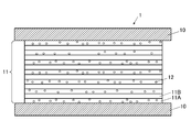
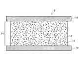
- Cross-sectional schematic diagram of holographic optical element Cross-sectional schematic diagram showing a photosensitive film
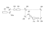
- Schematic showing an example of an exposure apparatus used for interference exposure
- the holographic optical element of the present invention is a holographic optical element in which a volume hologram recording layer is provided between two ultraviolet absorbing layers, wherein the volume hologram recording layer contains a high molecular weight resin composition. It has a refractive index layer and a low refractive index layer containing a low molecular weight resin composition obtained by decomposing the high molecular weight resin composition, and at least the high refractive index layer has photocatalyst fine particles dispersed therein. It is characterized by.
- This feature is a technical feature common to or corresponding to the claimed invention.
- the resin composition contained in the volume hologram recording layer contains a compound having an ether bond from the viewpoint of facilitating decomposition.
- the photocatalyst fine particles contain at least one of titanium oxide fine particles, zinc oxide fine particles and cadmium sulfide fine particles. Titanium oxide fine particles have a large photocatalytic activity, and zinc oxide fine particles and cadmium sulfide fine particles are decomposed by light irradiation. Therefore, when these photocatalytic fine particles are used, the refractive index difference between the high refractive index layer and the low refractive index layer is further increased. be able to.
- the method for producing a holographic optical element according to the present invention comprises subjecting a photosensitive composition containing a resin composition, photocatalyst fine particles for decomposing the resin composition, and a sensitizing dye for activating the photocatalyst to interference volume exposure. It has the process of forming a recording layer, It is characterized by the above-mentioned.
- the resin composition contained in the photosensitive layer contains a compound having an ether bond from the viewpoint of facilitating decomposition.
- the absorption maximum wavelength of the sensitizing dye is in the range of 400 to 700 nm from the viewpoint of manifesting the effect of the present invention.
- the photocatalyst fine particles contain at least one of zinc oxide fine particles and cadmium sulfide fine particles. Titanium oxide fine particles have a large photocatalytic activity, and zinc oxide fine particles and cadmium sulfide fine particles are decomposed by light irradiation. Therefore, when these photocatalytic fine particles are used, the refractive index difference between the high refractive index layer and the low refractive index layer is further increased. be able to.
- X to Y indicating a range means “X or more and Y or less”.
- the holographic optical element 1 has a configuration in which a volume hologram recording layer 11 is provided between two ultraviolet absorbing layers 10, and the volume hologram recording layer 11 includes a high refractive index layer 11A containing a high molecular weight resin composition. And a low refractive index layer 11B containing a low molecular weight resin composition obtained by decomposing the high molecular weight resin composition, and photocatalyst fine particles 12 are dispersed in at least the high refractive index layer 11A.
- FIG. 1 shows an example in which zinc oxide (ZnO) decomposed by light irradiation is used as the photocatalyst fine particles 12.
- ZnO zinc oxide
- the volume hologram recording layer contains photocatalyst particles that are activated (excited) by ultraviolet rays. However, since the ultraviolet rays are cut by the ultraviolet absorption layer sandwiching the volume hologram recording layer, the photocatalytic reaction occurs in the volume hologram recording layer. Not proceed.
- the photosensitive layer which is a volume hologram recording layer before the interference exposure, contains a sensitizing dye that can activate the photocatalyst with visible light (see FIG. 2). In the volume hologram recording layer after the interference exposure, Since the sensitizing dye is decolored by heat treatment or the like, the photocatalytic reaction does not proceed even when the volume hologram recording layer is irradiated with visible light. In the example of the holographic optical element in FIG.
- the ultraviolet absorbing layer 10 is provided on the upper and lower surfaces in the stacking direction in which the high refractive index layers 11A and the low refractive index layers 11B are alternately stacked.
- the ultraviolet absorbing layer 10 may be provided on the left and right surfaces in a direction perpendicular to the stacking direction.
- the ultraviolet absorbing layer (base material), any material can be used as long as it has necessary strength and durability and can cut ultraviolet rays.
- an ultraviolet absorber is added to a transparent material. Things can be used.
- Preferred transparent materials used for the ultraviolet absorbing layer include inorganic materials such as glass, silicone and quartz, organic materials such as polybutylene terephthalate (PET), polyethylene naphthalate (PEN), acrylic resin, and cycloolefin copolymer (COC). Is mentioned.
- the surface of the ultraviolet absorbing layer may be subjected to a surface treatment.
- This surface treatment is usually performed in order to improve the adhesion between the ultraviolet absorbing layer and the volume hologram recording layer.
- the surface treatment include performing a corona discharge treatment on the ultraviolet absorbing layer or forming an undercoat layer in advance on the ultraviolet absorbing layer.
- the composition of the undercoat layer include halogenated phenol, partially hydrolyzed vinyl chloride-vinyl acetate copolymer, polyurethane resin, and the like.
- the surface treatment may be performed for purposes other than improving the adhesiveness.
- examples thereof include a reflective coating treatment for forming a reflective coating layer made of a metal such as gold, silver, and aluminum; a dielectric coating treatment for forming a dielectric layer such as magnesium fluoride and zirconium oxide, and the like. It is done.
- these layers may be formed of a single layer or two or more layers.
- These surface treatments may be provided for the purpose of controlling the gas and moisture permeability of the holographic optical element. Thereby, the reliability of the holographic optical element can be further improved.
- the ultraviolet absorbing layer needs to be provided on both the upper side and the lower side of the holographic optical element, and is made of a transparent material so as to transmit active energy rays (recording light, reference light, reproduction light, etc.).
- a highly transparent adhesive such as a silicone adhesive or an acrylic adhesive can be used.
- the volume hologram recording layer has a high refractive index layer containing a high molecular weight resin composition and a low refractive index layer containing a low molecular weight resin composition obtained by decomposing the high molecular weight resin composition.
- the high refractive index layer and the low refractive index layer are alternately laminated.
- the volume hologram recording layer is a layer in which a volume hologram is recorded by interference exposure on a photosensitive layer containing photocatalyst fine particles and a sensitizing dye in a resin composition described later.
- the “high molecular weight” of the “high molecular weight resin composition” of the volume hologram recording layer refers to the molecular weight before being decomposed by the photocatalyst.
- the “low molecular weight” of the “low molecular weight resin composition obtained by decomposing a high molecular weight resin composition” of the volume hologram recording layer is a weight average from the molecular weight before being decomposed by the photocatalyst.
- the molecular weight (Mw) is a molecular weight that is less than half.
- photocatalyst fine particles are dispersed in at least the high refractive index layer of the volume hologram recording layer.
- photocatalyst fine particles metal fine particles
- the photocatalyst fine particles are dispersed in the volume hologram recording layer, it is a layer having a high refractive index as a whole. Therefore, when the ultraviolet absorbing layer is a layer having a high refractive index such as a PET film, the difference in refractive index between the ultraviolet absorbing layer and the volume hologram recording layer can be reduced, so that reflection at the interface between the ultraviolet absorbing layer and the volume hologram recording layer can be achieved. (Generation of ghost light) can be made difficult to occur.
- the layer thickness of the volume hologram recording layer is not particularly limited, but is preferably 10 to 100 ⁇ m, more preferably 20 to 50 ⁇ m from the viewpoint of durability.
- the layer thickness of the high refractive index layer and the low refractive index layer is not particularly limited, but is preferably formed to be 400 nm or less.
- the “layer thickness” refers to the thickness in the stacking direction of the volume hologram recording layer.
- the resin constituting the volume hologram recording layer is not limited as long as it contains a resin composition that is easily decomposed by a photocatalyst.
- the resin composition preferably contains a compound having an ether bond.
- thermoplastic resin for example, a thermoplastic resin, a thermosetting resin, an active energy ray curable resin and the like can be used without limitation, and can be used alone or in combination of two or more.
- thermoplastic resins include, for example, polyethylene glycol methyl ether, polyether ether ketone, polyphenylene ether, polyether ketone, polyether sulfone, polyvinyl acetate, polyvinyl butyrate, polyvinyl formal, polyvinyl carbazole, polyacrylic acid, poly Methacrylic acid, polymethyl acrylate, polymethyl methacrylate, polyethyl acrylate, polybutyl acrylate, polymethacrylonitrile, polyethyl methacrylate, polybutyl methacrylate, polyacrylonitrile, poly-1,2-dichloroethylene, ethylene-vinyl acetate copolymer , Syndiotactic polymethyl methacrylate, poly- ⁇ -vinyl naphthalate, polycarbonate, cellulose acetate, Rulose triacetate, cellulose acetate butyrate, polystyrene, poly- ⁇ -methylstyrene, poly-o-methyls
- thermosetting resin examples include unsaturated polyester, acrylic urethane resin, epoxy-modified acrylic resin, epoxy-modified unsaturated polyester, polyurethane, alkyd resin, phenol resin and the like.
- Examples of the active energy ray-curable resin include epoxy acrylate, urethane acrylate, and acrylic-modified polyester. These active energy ray-curable resins can include other monofunctional or polyfunctional monomers, oligomers, and the like as described below for the purpose of adjusting the cross-linked structure and viscosity.
- mono (meth) acrylates such as tetrahydrofurfuryl (meth) acrylate, hydroxyethyl (meth) acrylate, vinyl pyrrolidone, (meth) acryloyloxyethyl succinate, (meth) acryloyloxyethyl phthalate, etc.
- polyol (meth) acrylate epoxy-modified polyol (meth) acrylate, lactone-modified polyol (meth) acrylate, etc.
- polyester (meth) acrylate epoxy (meth) acrylate, urethane (meth) acrylate, and other polybutadienes
- Poly (meth) acrylates with isocyanuric acid-based, hydantoin-based, melamine-based, phosphoric acid-based, imide-based, phosphazene-based skeletons, and are UV- and electron-beam curable Monomers, oligomers, polymers may be utilized such.
- the photocatalyst fine particles are not particularly limited, but zinc oxide (ZnO), cadmium sulfide (CdS), tungsten oxide (WO 3 ), titanium oxide (TiO 2 ), zirconium oxide (ZrO 2 ), tin oxide (SnO) 3 ) and the like can be used. Among these, it is preferable to use titanium oxide fine particles having high photocatalytic activity or fine particles of zinc oxide (ZnO) or cadmium sulfide (CdS) that are decomposed by light irradiation.
- the difference in molecular weight between the compounds contained in the resin composition of the high refractive index layer and the low refractive index layer can be further increased. This is because only the photocatalyst fine particles in the low refractive index layer are decomposed by irradiation, so that the difference in refractive index between the high refractive index layer and the low refractive index layer can be increased. And thereby, the half value width of the diffraction peak of a holographic optical element can be made narrower.
- the average particle diameter of the photocatalyst fine particles is not particularly limited as long as the refractive index of the volume hologram recording layer can be increased and transparency can be secured when dispersed in the resin constituting the volume hologram recording layer, but it is in the range of 5 to 50 nm. It is preferable to be within. Further, the “average particle diameter” in the present specification refers to a volume-based average particle diameter corresponding to 50% of the cumulative distribution obtained by a particle size distribution measuring apparatus using a dynamic light scattering method.
- a plasticizer for the volume hologram recording layer, if necessary, a plasticizer, a compatibilizer, a polymerization inhibitor, a surfactant, a silane coupling agent, an antifoaming agent, a release agent, a stabilizer, an antioxidant, a flame retardant, Additives such as an optical brightener and an ultraviolet absorber may further be included.
- a method for producing a holographic optical element includes a volume hologram recording layer formed by interference exposure of a photosensitive layer containing a resin composition, photocatalyst fine particles that decompose the resin composition, and a sensitizing dye that activates the photocatalyst. It has the process of forming.
- FIG. 2 is a schematic cross-sectional view showing a holographic optical element (hereinafter, also referred to as a photosensitive film) in the middle of production immediately before the interference exposure.
- the photosensitive film 2 is obtained by applying a hologram recording material solution on the ultraviolet absorbing layer 10 and drying it to form the photosensitive layer 13, and further laminating the ultraviolet absorbing layer 10 on the photosensitive layer 13. is there.
- the photosensitive layer 13 contains a resin composition, photocatalyst fine particles 12 that decompose the resin composition, and a sensitizing dye 14 that activates the photocatalyst.
- the photocatalyst is usually activated only by ultraviolet rays. However, since the sensitizing dye activated by visible light activates the photocatalyst, the photocatalytic reaction can be promoted by irradiation with visible light.
- the hologram recording material contains at least photocatalyst fine particles and a sensitizing dye in a resin composition serving as a binder. Since the resin is the same as the resin constituting the volume hologram recording layer described above, the description thereof is omitted. In addition to the photocatalyst fine particles and the sensitizing dye, the above-described other additives may be added to the hologram recording material.
- Photocatalyst fine particles similar to those of the volume hologram recording layer described above can be used.
- the content of the photocatalyst fine particles is preferably in the range of 5 to 50% by mass with respect to the total amount of the hologram recording material excluding the solvent, from the viewpoint of sufficiently decomposing the resin composition.
- sensitizing dye The photocatalyst fine particles are preferably used together with a sensitizing dye having an absorption maximum wavelength in the range of 400 to 700 nm. When the sensitizing dye absorbs light in the above range, a sensitizing action can be generated on the photocatalyst.
- sensitizing dyes include polymethine compounds such as cyanine dyes and styryl dyes, xanthene compounds such as rhodamine B, rhodamine 6G, and pyronin GY, phenazine compounds such as safranin O, cresyl violet, and brilliant cresyl.
- Phenoxazine compounds such as blue, phenothiazine compounds such as methylene blue and new methylene blue, diarylmethane compounds such as auramine, triarylmethane compounds such as crystal violet, brilliant green and lissamine green, (thio) pyrylium salt compounds , Squarylium compounds, coumarin dyes, thioxanthene dyes, acene dyes, merocyanine dyes, thiazolium dyes, and the like can be used. These sensitizing dyes can be used alone or in combination of two or more.
- sensitizing dyes examples include 3,3′-diethylthiacarbocyanine iodide, 3,3′-dipropylthiadicarbocyanine iodide, 2,4-bis [4- (diethylamino)- 2-hydroxyphenyl] squarein, 2,4-bis [8-hydroxy-1,1,7,7-tetramethyljulolidin-9-yl] squarein, basic blue 7, crocin and the like can be used.
- the content of the sensitizing dye is preferably in the range of 0.1 to 10% by mass with respect to the total amount of the hologram recording material excluding the solvent.
- solvent A solvent may be added to the hologram recording material, if necessary, when the hologram recording material is applied to the ultraviolet absorbing layer. However, when the hologram recording material contains a component that is liquid at room temperature, a solvent may not be necessary.
- the solvent examples include aliphatic solvents such as n-pentane, n-hexane, n-heptane, n-octane, cyclohexane and methylcyclohexane; ketone solvents such as methyl ethyl ketone (2-butanone), acetone and cyclohexanone; diethyl Ether solvents such as ether, isopropyl ether, tetrahydrofuran, dioxane, ethylene glycol dimethyl ether, ethylene glycol diethyl ether, diethylene glycol dimethyl ether, diethylene glycol diethyl ether, propylene glycol monomethyl ether, anisole, phenetole; ethyl acetate, butyl acetate, ethylene glycol diacetate, etc.
- aliphatic solvents such as n-pentane, n-hexane, n-heptane, n
- Ester solvents aromatic solvents such as toluene and xylene; methyl cellosolve, ethyl cello Cellosolve solvents such as Rub and Butylcellosolve; Alcohol solvents such as methanol, ethanol, propanol and isopropyl alcohol; Ether solvents such as tetrahydrofuran and dioxane; Halogen solvents such as dichloromethane and chloroform; Nitriles such as acetonitrile and propionitrile Solvent; polar solvents such as N-methyl-2-pyrrolidone, N-ethyl-2-pyrrolidone, N, N-dimethylformamide, N, N-dimethylacetamide and the like. These solvents can be used alone or in combination of two or more.
- the hologram recording material can be obtained by mixing the above-described components all together or sequentially.
- the apparatus used for mixing include stirring or mixing apparatuses such as a magnetic stirrer, homodisper, quick homomixer, and planetary mixer.
- the obtained hologram recording material may be used after being filtered, if necessary.
- the photosensitive layer is formed by applying a hologram recording material solution on the ultraviolet absorbing layer and drying it.
- the thickness of the formed photosensitive layer is not particularly limited, but is preferably 10 to 100 ⁇ m and more preferably 20 to 50 ⁇ m from the viewpoint of forming a durable volume hologram recording layer.
- a conventionally known method can be used as a method of applying the hologram recording material to the ultraviolet absorbing layer.
- a conventionally known method can be used. Specific examples include a spray method, a spin coat method, a wire bar method, a dip coat method, an air knife coat method, a roll coat method, a blade coat method, and a doctor roll coat method.
- the drying method various conventionally known methods using a hot plate, oven, belt furnace or the like can be adopted.
- the drying temperature is not particularly limited, and is, for example, in the range of 10 to 80 ° C.
- the drying time is not particularly limited, and is, for example, in the range of 1 to 60 minutes.
- the volume hologram recording layer is formed by performing interference exposure (holographic exposure) on a photosensitive layer containing a resin composition, photocatalyst fine particles that decompose the resin composition, and a sensitizing dye that activates the photocatalyst. .
- interference exposure holographic exposure
- the photosensitive layer By subjecting the photosensitive layer to interference exposure, the photocatalyst is activated and the resin composition is decomposed in a strong light region (hereinafter, also referred to as “light irradiation region”), and the light composition (hereinafter referred to as “non-irradiation region”). In this case, the resin composition is not decomposed.
- the light irradiation region and the non-irradiation region have different molecular weights of the compounds contained in the resin composition, and regions having different refractive indexes are formed. That is, the pattern of the high refractive index layer and the low refractive index layer formed on the volume hologram recording layer is formed in the same pattern as the interference wave irradiated by the interference exposure.
- the method of performing interference exposure on the photosensitive layer and recording (writing) the volume hologram is not particularly limited, and examples thereof include the following method.
- recording information light having a wavelength capable of activating the sensitizing dye is used as recording light (also referred to as object light).
- the interference light causes a decomposition reaction of the resin composition in the photosensitive layer.
- the interference fringes cause a refractive index difference in the photosensitive layer, and are recorded as a volume hologram by the interference fringes recorded in the photosensitive layer to form a volume hologram recording layer.
- the recording light used for recording the volume hologram (the wavelength in the parentheses indicates a wavelength)
- a visible light laser having excellent coherence for example, an argon ion laser (458 nm, 488 nm, 514 nm), a krypton ion laser (647). 0.1 nm), helium-neon laser (633 nm), YAG laser (532 nm), etc. can be used.
- the irradiation energy amount (exposure amount) at the time of hologram recording is not particularly limited, but is preferably in the range of 10 to 10,000 mJ / cm 2 .
- a hologram recording system there are a polarization collinear hologram recording system, a reference light incident angle multiplexing type hologram recording system, etc., and any recording system can provide good recording quality.
- the exposure apparatus is not particularly limited.
- an exposure apparatus having a schematic configuration shown in FIG. 4 can be used.
- the light beam (recording light) emitted from the laser light source 201 guides the light beam to a suitable position in the exposure system by the beam steerers 202a and 202b composed of two pairs of mirrors.
- a shutter 203 controls ON / OFF of a light beam (recording light).
- a beam expander 204 has a function of expanding the beam diameter and changing the aperture ratio (NA) according to the exposure area of the photosensitive layer.
- the light beam (recording light) that has passed through the beam expander 204 is divided into two light beams by the beam splitter 205.
- the divided light beams (recording light) are guided to the spatial filters 211 and 212 by the mirrors 206 and 207 and the mirrors 209 and 208, respectively.
- Spatial filters 211 and 212 are composed of a lens and a pinhole, and collect light rays (recording light) with the lenses, and guide the light rays (recording light) to the manufacturing optical system 213 through the pinholes.
- the production optical system 213 has a sample such as a glass or optical plastic prism provided with a photosensitive layer serving as a volume hologram recording layer placed at a suitable position so that the reflection angle of the light beam of the holographic optical element can be controlled. Can be fixed.
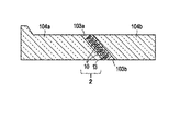
- FIG. 3 shows an example of a state in which the photosensitive layer 13 sandwiched between the ultraviolet absorbing layers 10 is sandwiched between a pair of prism bases 104a and 104b coated with silicone adhesives 103a and 103b.
- a photosensitive layer provided on a prism or the like fixed to the manufacturing optical system 213 is divided into two light beams, and is subjected to interference exposure (holographic exposure) by light beams (recording light) guided through the spatial filters 211 and 212, respectively.
- a dichroic mirror is inserted in the optical path before the shutter 203 to emit light from the plurality of light sources.
- the laser beam to be generated may be synthesized stepwise.
- the volume hologram recording layer can be further subjected to a treatment such as heating for the purpose of promoting the refractive index modulation and completing the decomposition reaction.
- a treatment such as heating for the purpose of promoting the refractive index modulation and completing the decomposition reaction.
- the temperature during the heat treatment is preferably 50 to 150 ° C.
- the treatment time is preferably 30 minutes to 3 hours.
- the volume hologram recorded on the volume hologram recording layer is reproduced by irradiating the volume hologram recording layer with predetermined reproduction light (usually reference light).
- the irradiated reproduction light is diffracted according to the interference fringes. Since this diffracted light contains the same information as the volume hologram recording layer, the information recorded on the volume hologram recording layer can be reproduced by reading the diffracted light with an appropriate detection means.
- the holographic optical element of the present embodiment may have other layers such as a protective layer and an antireflection film.
- the protective layer is a layer for preventing the influence of deterioration of storage stability of the recording layer.
- a protective layer There is no restriction
- a layer made of a water-soluble polymer, an organic / inorganic material, or the like can be formed as a protective layer.
- limiting in particular in the formation position of a protective layer For example, you may form between a volume hologram recording layer and an ultraviolet absorption layer, and may form in the outer surface side of an ultraviolet absorption layer.
- an antireflection film is provided on the side on which object light and reproduction light enter and exit, or between the volume hologram recording layer and the ultraviolet absorbing layer. Also good.
- the antireflection film functions to improve light utilization efficiency and suppress the generation of ghost images.
- As the antireflection film conventionally known ones can be referred to as appropriate.
- the holographic optical element of the present embodiment includes, for example, a head mounted display (HMD), a head-up display (HUD), an optical memory, an optical disk pickup lens, a liquid crystal color filter, a reflective liquid crystal reflector, a lens, a diffraction grating, and an interference.
- HMD head mounted display
- HUD head-up display
- an optical memory for example, a liquid crystal color filter, a reflective liquid crystal reflector, a lens, a diffraction grating, and an interference.
- holographic optical element 1 100 parts by mass of titanium oxide fine particles (ST-01, manufactured by Ishihara Sangyo) with an average particle diameter of 20 nm as photocatalyst fine particles, and 200 parts by mass of polyethylene glycol methyl ether (mPEG, manufactured by Sigma Aldrich) with a weight average molecular weight of 200,000 as resin.
- a holographic optical element 1 having a volume hologram recording layer was obtained by performing a heat treatment at 100 ° C. for 3 hours.
- holographic optical elements 2 to 6 Production of holographic optical elements 2 to 6
- the sensitizing dye was changed in the same manner except that the sensitizing dye was changed from 3,3′-diethylthiacarbocyanine iodide (S1) to the sensitizing dyes (S2 to S6) shown in Table 1.
- S1 represents 3,3′-diethylthiacarbocyanine iodide.
- S2 represents 3,3′-dipropylthiadicarbocyanine iodide (manufactured by Tokyo Chemical Industry).
- S3 represents 2,4-bis [4- (diethylamino) -2-hydroxyphenyl] squarein (manufactured by Tokyo Chemical Industry).
- S4 represents 2,4-bis [8-hydroxy-1,1,7,7-tetramethyljulolidin-9-yl] squarein (manufactured by Tokyo Chemical Industry).
- S5 represents Basic Blue 7 (manufactured by Tokyo Chemical Industry).
- S6 represents crocin (manufactured by Tokyo Chemical Industry).
- the absorption maximum wavelengths of the sensitizing dyes are S1 of 555 nm, S2 of 640 nm, S3 of 645 nm, S4 of 670 nm, S5 of 615 nm, and S6 of 440 nm.
- holographic optical element 7 Production of holographic optical element 7
- the photocatalyst fine particles are changed from titanium oxide fine particles having an average particle size of 20 nm (ST-01 manufactured by Ishihara Sangyo) to zinc oxide fine particles having an average particle size of 20 nm (FINEX-50 manufactured by Sakai Chemical Industry).
- a holographic optical element 7 was produced in the same manner except that.
- holographic optical elements 8-12 Production of holographic optical elements 8-12
- the sensitizing dye was changed in the same manner except that 3,3′-diethylthiacarbocyanine iodide (S1) was changed to the sensitizing dyes (S2 to S6) shown in Table 1.
- S1 3,3′-diethylthiacarbocyanine iodide
- S2 to S6 the sensitizing dyes shown in Table 1.
- holographic optical element 13 ⁇ Production of holographic optical element 13
- the photocatalyst fine particles were changed from titanium oxide fine particles having an average particle size of 20 nm (ST-01 made by Ishihara Sangyo) to tungsten oxide fine particles having an average particle size of 50 nm (W691 made by Hong International Group).
- a holographic optical element 13 was produced.
- holographic optical elements 14-18 Production of holographic optical elements 14-18
- the sensitizing dye was changed from 3,3′-diethylthiacarbocyanine iodide (S1) to the sensitizing dyes (S2 to S6) shown in Table 1 in the same manner.
- S1 3,3′-diethylthiacarbocyanine iodide
- S2 to S6 the sensitizing dyes shown in Table 1 in the same manner.
- holographic optical elements 14 to 18 were produced.
- holographic optical element 19 Production of holographic optical element 19
- the photocatalyst fine particles were changed from titanium oxide fine particles having an average particle size of 20 nm (ST-01 manufactured by Ishihara Sangyo) to cadmium sulfide fine particles having an average particle size of 20 nm prepared as described below.
- a holographic optical element 19 was produced.
- a mixture of 50 mL of a 0.1 mol / L sodium sulfide solution and 10 mL of a 1 mol / L sodium sulfite solution was suspended therein, and this suspension was irradiated with simulated sunlight using a 500 W-Xe lamp. .
- the particle color changed from reddish brown to green brown, and hydrogen was generated.
- the suspension was subjected to suction filtration, and the photocatalyst powder was dried together with the filter. Thereby, cadmium sulfide fine particles having a greenish brown color on the filter were obtained, and the average particle size was 20 nm.
- holographic optical elements 25-30 In the production of the holographic optical elements 1 to 6, a holographic optical element was similarly obtained except that the resin was changed from polyethylene glycol methyl ether (mPEG, manufactured by Sigma Aldrich) to polymethyl methacrylate resin (PMMA, manufactured by Sigma Aldrich). 25-30 were produced.
- mPEG polyethylene glycol methyl ether
- PMMA polymethyl methacrylate resin
- Titanium oxide sol TKS-251 (20% by mass toluene solution) having an average particle diameter of 10 nm made by Teika as the metal oxide fine particles, 250 parts by mass as a coupling agent, Prenact KR TTS (one isopropoxy group made by Ajinomoto Fine Techno) And 1 part by weight of titanate having three -O-CO-C 17 H 35 groups), 50 parts by weight of 2-phenoxyethyl acrylate as a polymerizable monomer, 1 part of DAROCURE 1173 from BASF as a photopolymerization initiator As a sensitizing dye, 0.13 parts by mass of 3,3′-diethylthiacarbocyanine iodide made by Tokyo Chemical Industry is added to a container and mixed, and stirred to stir the metal oxide fine particles in the solution.
- a hologram recording material solution was prepared by uniformly dispersing.
- regions having different refractive indexes can be formed in a strong light region and a weak light region.
- the holographic optical elements 1 to 30 of the example form the volume hologram recording layer by the decomposition reaction by the photocatalyst
- the holographic optical elements 31 and 32 of the comparative example have the volume hologram recording by the polymerization reaction by the photocatalyst. A layer was formed.
- the light transmittance was measured using a spectrophotometer U-3900 (manufactured by Hitachi, Ltd.) under the conditions of a measurement wavelength of 350 to 800 nm, a scan speed of 600 nm / min, and a measurement region of 3 mm. Then, the baseline of the diffraction spectrum is calculated, and the wavelength width at the light transmittance intermediate between the light transmittance and the baseline light transmittance at the diffraction grating ⁇ max is defined as the half width of the diffraction peak, and the half width of the diffraction peak is evaluated. Went. A half-value width of 45 nm or less was accepted. The results are shown in Table 1.
- the holographic optical element was evaluated for light transmittance at a wavelength of 450 nm using a spectrophotometer U-3900 (manufactured by Hitachi, Ltd.) under the same conditions as described above.
- the light transmittance at a wavelength of 450 nm was determined to be 75% or more. The results are shown in Table 1.
- the holographic optical element was evaluated for whether reflection occurs at the interface between the base material (ultraviolet absorbing layer) and the volume hologram recording layer (ghost light is generated). Specifically, it is assumed that ghost light is generated when an image is projected using each holographic optical element, the projected image is visually observed, and an image is formed at an unintended location. The case where no ghost light was generated was evaluated as ⁇ , and the case where ghost light was generated was evaluated as x. The results are shown in Table 1.
- the holographic optical elements 1 to 30 of the examples have a high light transmittance at a wavelength of 450 nm, a small half-value width of the diffraction peak, and a base material (ultraviolet absorption layer). It was found that it was difficult to reflect at the interface (no ghost light was generated). On the other hand, the holographic optical elements 31 and 32 of the comparative example were inferior in any item.
- the holographic optical element 31 as a comparative example has a volume hologram recording layer formed by interference exposure on a photosensitive layer containing metal oxide fine particles, a polymerizable monomer, a photopolymerization initiator, and the like. It is a method of forming. In this method, a polymerizable monomer is photopolymerized in a region with strong light to form a polymer. In addition, since the concentration of the polymerizable monomer is reduced in the region where the light is strong, the polymerizable monomer is supplied by diffusion from the region where the light is weak, and the formation of the polymer is promoted.
- a volume hologram recording layer can be formed.
- a holographic optical element 32 as a comparative example is a method for forming a volume hologram recording layer by performing interference exposure on a photosensitive layer containing a polymerizable monomer, a photopolymerization initiator, a thermoplastic resin, and the like. It is.
- a polymerizable monomer is photopolymerized in a region with strong light to form a polymer.
- the concentration of the polymerizable monomer is reduced in the region where the light is strong, the polymerizable monomer is supplied by diffusion from the region where the light is weak, and the formation of the polymer is promoted.
- the thermoplastic thermoplastic resin component is extruded from the strong light region where the polymer is formed into the weak light region, a volume hologram recording layer having regions having different refractive indexes can be formed.
- the holographic optical elements 31 and 32 of these comparative examples are manufactured by a conventional method for manufacturing a holographic optical element that involves movement of molecules.
- a production method involving movement of molecules since the polymerization reaction rate of the monomer is faster than the movement rate of the molecules, the movement of the molecules cannot be performed completely, and this is caused by the components remaining in the polymer. Thus, it is considered that the light transmittance was lowered. Further, it is considered that the interface between the high refractive index layer and the low refractive index layer could not be sharply formed due to the molecules that could not move, and the half width of the diffraction peak was increased.
- the holographic optical element 31 and 32 of the comparative example ghost light was generated. Since the holographic optical element 32 does not contain metal particles having a high refractive index in the volume hologram recording layer, a high refractive index volume hologram recording layer cannot be formed, and a high refractive index substrate (ultraviolet absorption layer) and It is thought that ghost light was generated due to reflection at the interface.
- the holographic optical element 31 contains metal fine particles having a high refractive index in the volume hologram recording layer, a sufficient amount of metal fine particles can be moved in the vicinity of the base material (ultraviolet absorption layer) having a high refractive index. Therefore, it is considered that reflection occurred at the interface with the base material (ultraviolet absorption layer) having a high refractive index and ghost light was generated.
- the holographic optical elements 1 to 30 of the examples are manufactured by a method that does not involve the movement of molecules, there is no molecule that failed to move as in the comparative example, and the movement failed. It is considered that the light transmittance was increased because the components did not cause white turbidity.
- only the light irradiation region is selectively decomposed and a difference in refractive index is generated in the volume hologram recording layer, so that the interface between the light irradiation region and the non-irradiation region can be formed more sharply, and the half-value width of the diffraction peak can be reduced. It seems that it was made narrower.
- a high refractive index layer can be formed, and a PET film substrate (ultraviolet absorbing layer) having a high refractive index can be formed. It is considered that reflection (generation of ghost light) did not occur at the interface with
- the holographic optical elements 1 to 24 use a compound having an ether bond as the resin constituting the photosensitive layer, the decomposition reaction of the resin by the photocatalyst easily proceeds, and the high refractive index layer and the low refractive index It is thought that the difference in the molecular weight of the compounds contained in the resin composition of the layer could be made larger. As a result, the refractive index difference between the high refractive index layer and the low refractive index layer can be increased, and the interface between the high refractive index layer and the low refractive index layer can be more sharply formed. It seems that it was made narrower.
- the holographic optical elements 1 to 6 using titanium oxide (TiO 2 ) fine particles as photocatalyst fine particles have a high light transmittance and a narrow half-value width of the diffraction peak. . This is considered to be because the photocatalytic activity of the titanium oxide fine particles was large and the difference in molecular weight between the compounds contained in the resin composition of the high refractive index layer and the low refractive index layer could be further increased.
- the holographic optical elements 7 to 12 and 19 to 24 using zinc oxide (ZnO) or cadmium sulfide (CdS) fine particles as photocatalyst fine particles have particularly narrow half-widths of diffraction peaks. This is thought to be because the difference in refractive index between the high refractive index layer and the low refractive index layer was increased as a result of the photoirradiation of the photocatalyst fine particles in the low refractive index layer being excited, decomposed, and disappeared by light irradiation. .
- the holographic optical element of the present embodiment includes, for example, a head mounted display (HMD), a head-up display (HUD), an optical memory, an optical disk pickup lens, a liquid crystal color filter, a reflective liquid crystal reflector, a lens, a diffraction grating, and an interference.
- HMD head mounted display
- HUD head-up display
- an optical memory for example, a hard disk drive (HDD)
- an optical disk pickup lens for example, a liquid crystal color filter, a reflective liquid crystal reflector, a lens, a diffraction grating, and an interference.
- Suitable for use in credit cards, banknotes, packaging, etc. for security purposes such as filters, optical fiber couplers, facsimile light polarizers, architectural window glass, covers for books, magazines, displays such as POPs, gifts, and counterfeiting it can.
Landscapes
- Physics & Mathematics (AREA)
- General Physics & Mathematics (AREA)
- Optics & Photonics (AREA)
- Holo Graphy (AREA)
- Diffracting Gratings Or Hologram Optical Elements (AREA)
Abstract
解決しようとする課題は、光透過率が高く、回折ピークの半値幅が小さく、ゴースト光が抑制されたホログラフィック光学素子及びその製造方法を提供することである。上記課題は、二つの紫外線吸収層10の間に体積ホログラム記録層11が設けられたホログラフィック光学素子1であって、体積ホログラム記録層11が、高分子量の樹脂組成物を含有する高屈折率層11Aと、当該高分子量の樹脂組成物が分解された低分子量の樹脂組成物を含有する低屈折率層11Bを有し、少なくとも高屈折率層11Aには、光触媒微粒子12が分散されているホログラフィック光学素子1によって解決される。
Description
本発明は、光触媒を用いたホログラフィック光学素子に関する。より詳細には、本発明は、光透過率が高く、回折ピークの半値幅が小さく、ゴースト光が抑制されたホログラフィック光学素子及びその製造方法に関する。
体積ホログラム記録層を有するホログラフィック光学素子は、光コンバイナとして機能し、光学レンズ、表示素子等に応用され、需要が高まりつつある。とりわけ、ヘッドマウントディスプレイやヘッドアップディスプレイ等の表示素子としてのホログラフィック光学素子は、体積ホログラム記録層の透明性が高いが故、シースルータイプの表示素子として利用が可能である(例えば特許文献1)。
ホログラフィック光学素子の体積ホログラム記録層の形成方法としては、例えば、金属酸化物微粒子と、重合可能なモノマーと、光重合開始剤等とを含有する感光層に、干渉露光する方法が開示されている(特許文献2)。この方法では、光の強い領域にはポリマーが形成され、光の弱い領域には金属酸化物微粒子が押し出されるため、屈折率の異なる領域を有する体積ホログラム記録層を形成できる。
また、他の体積ホログラム記録層を形成する方法の例としては、重合可能なモノマーと、光重合開始剤と、熱可塑性樹脂等とを含有する感光層に、干渉露光する方法が開示されている(特許文献3)。この方法では、光の強い領域にはポリマーが形成され、光の弱い領域には熱可塑性樹脂成分が押し出されるため、屈折率の異なる領域を有する体積ホログラム記録層を形成できる。
しかしながら、これらの金属酸化物微粒子や熱可塑性樹脂成分等の構成成分の移動をともなう体積ホログラム記録層の形成方法では、モノマーの重合反応速度が、当該構成成分の移動速度よりも速いため、構成成分を完全に移動させて分離することは難しい。そのため、ポリマー中に残った構成成分が原因となって、体積ホログラム記録層に白濁が生じ、光透過率が低下するという問題があった。
また、これらの構成成分の移動をともなう製造方法では、屈折率の異なる層の屈折率差を大きくすることや、屈折率の異なる層の界面をシャープに形成することが難しく、回折ピークの半値幅が大きくなり、所望の波長以外も回折して光透過率が低下するという問題があった。
さらに、これらの構成成分の移動をともなう製造方法では、高屈折率の体積ホログラム記録層を形成することが難しいため、ポリエチレンテレフタレート(PET)フィルム等の高屈折率の基材(紫外線吸収層)上に体積ホログラム記録層を形成する場合、基材と体積ホログラム記録層との界面で反射が起きる(ゴースト光が発生する)という問題があった。上述したシースルータイプの表示素子での利用の高まりを鑑みると、従来のような、原理上、成分の移動を伴う製造方法では、十分その要請に応えることが難しくなっているものと思われ、従来の製造方法とは異なる原理に基づく新規な製造方法が必要となっている。
また、これらの構成成分の移動をともなう製造方法では、屈折率の異なる層の屈折率差を大きくすることや、屈折率の異なる層の界面をシャープに形成することが難しく、回折ピークの半値幅が大きくなり、所望の波長以外も回折して光透過率が低下するという問題があった。
さらに、これらの構成成分の移動をともなう製造方法では、高屈折率の体積ホログラム記録層を形成することが難しいため、ポリエチレンテレフタレート(PET)フィルム等の高屈折率の基材(紫外線吸収層)上に体積ホログラム記録層を形成する場合、基材と体積ホログラム記録層との界面で反射が起きる(ゴースト光が発生する)という問題があった。上述したシースルータイプの表示素子での利用の高まりを鑑みると、従来のような、原理上、成分の移動を伴う製造方法では、十分その要請に応えることが難しくなっているものと思われ、従来の製造方法とは異なる原理に基づく新規な製造方法が必要となっている。
本発明は上記問題及び状況に鑑みてなされたものであり、その解決課題は、光透過率が高く、回折ピークの半値幅が小さく、ゴースト光が抑制されたホログラフィック光学素子及びその製造方法を提供することである。
本発明者らは、上記課題を解決すべく、上記問題の原因等について検討する過程において、ホログラフィック光学素子の体積ホログラム記録層を、高分子量の樹脂組成物を含有する高屈折率層と、前記樹脂組成物が光触媒の分解反応によって分解された低分子量の樹脂組成物を含有する低屈折率層を有する構成とすることによって、透明度が高く、反射光選択性が高く、ゴースト光が抑制されたホログラフィック光学素子を提供できることを見いだし、本発明に至った。
すなわち、本発明に係る課題は、以下の手段によって解決される。
すなわち、本発明に係る課題は、以下の手段によって解決される。
1.二つの紫外線吸収層の間に体積ホログラム記録層が設けられたホログラフィック光学素子であって、
前記体積ホログラム記録層が、高分子量の樹脂組成物を含有する高屈折率層と、前記高分子量の樹脂組成物が分解された低分子量の樹脂組成物を含有する低屈折率層を有し、
少なくとも前記高屈折率層には、光触媒微粒子が分散されていることを特徴とするホログラフィック光学素子。
前記体積ホログラム記録層が、高分子量の樹脂組成物を含有する高屈折率層と、前記高分子量の樹脂組成物が分解された低分子量の樹脂組成物を含有する低屈折率層を有し、
少なくとも前記高屈折率層には、光触媒微粒子が分散されていることを特徴とするホログラフィック光学素子。
2.前記体積ホログラム記録層に含有される樹脂組成物が、エーテル結合を有する化合物を含有することを特徴とする第1項に記載のホログラフィック光学素子。
3.前記光触媒微粒子として、酸化チタン微粒子、酸化亜鉛微粒子及び硫化カドミウム微粒子のうち少なくとも一種を含有することを特徴とする第1項又は第2項に記載のホログラフィック光学素子。
4.樹脂組成物と、前記樹脂組成物を分解する光触媒微粒子と、光触媒を活性化する増感色素とを含有する感光層を、干渉露光することによって体積ホログラム記録層を形成する工程を有することを特徴とするホログラフィック光学素子の製造方法。
5.前記感光層に含有される前記樹脂組成物が、エーテル結合を有する化合物を含有することを特徴とする第4項に記載のホログラフィック光学素子の製造方法。
6.前記増感色素の吸収極大波長が、400~700nmの範囲内であることを特徴とする第4項又は第5項に記載のホログラフィック光学素子の製造方法。
7.前記光触媒微粒子として、酸化チタン微粒子、酸化亜鉛微粒子及び硫化カドミウム微粒子のうち少なくとも一種を含有することを特徴とする第4項から第6項までのいずれか一項に記載のホログラフィック光学素子の製造方法。
本発明の上記手段により、光透過率が高く、回折ピークの半値幅が小さく、ゴースト光が抑制されたホログラフィック光学素子及びその製造方法を提供することができる。
上記効果の発現機構又は作用機構については、明確にはなっていないが、以下のように推察している。
上記効果の発現機構又は作用機構については、明確にはなっていないが、以下のように推察している。
本発明のホログラフィック光学素子に係る体積ホログラム記録層は、樹脂組成物と、光触媒微粒子と、光触媒を活性化(励起)する増感色素とを含有する感光層を干渉露光することで、光の強い領域(以下、「光照射領域」ともいう。)において光触媒が活性化され、光照射領域の樹脂組成物が分解されることで形成される。ここで、光の弱い領域(以下、「非照射領域」ともいう。)では、樹脂組成分が分解されないため、光照射領域と非照射領域では、樹脂組成物に含有されている化合物の分子量が異なり、屈折率の異なる領域が形成されている。
また、本発明のホログラフィック光学素子の製造方法では、構成成分の移動をともなわないので、移動し損なった構成成分が原因となって白濁が生じることはなく、光透過率の高いホログラフィック光学素子とすることができると考えられる。
また、光照射領域のみが分解反応されて、体積ホログラム記録層内に屈折率差を生じさせるので、光照射領域と非照射領域の界面をよりシャープに形成でき、回折ピークの半値幅を狭くできると考えられる。
さらに、体積ホログラム記録層の少なくとも高屈折率層は、酸化亜鉛微粒子等の光触媒微粒子が分散された状態となっているため、高屈折率な体積ホログラム記録層となっている。そのため、紫外線吸収剤を含むポリエチレンテレフタレート(PET)フィルム等の高屈折率の基材(紫外線吸収層)上に体積ホログラム記録層を形成した場合であっても、基材と体積ホログラム記録層の屈折率差を小さくでき、ゴースト光を抑制できたと考えられる。
また、光照射領域のみが分解反応されて、体積ホログラム記録層内に屈折率差を生じさせるので、光照射領域と非照射領域の界面をよりシャープに形成でき、回折ピークの半値幅を狭くできると考えられる。
さらに、体積ホログラム記録層の少なくとも高屈折率層は、酸化亜鉛微粒子等の光触媒微粒子が分散された状態となっているため、高屈折率な体積ホログラム記録層となっている。そのため、紫外線吸収剤を含むポリエチレンテレフタレート(PET)フィルム等の高屈折率の基材(紫外線吸収層)上に体積ホログラム記録層を形成した場合であっても、基材と体積ホログラム記録層の屈折率差を小さくでき、ゴースト光を抑制できたと考えられる。
本発明のホログラフィック光学素子は、二つの紫外線吸収層の間に体積ホログラム記録層が設けられたホログラフィック光学素子であって、前記体積ホログラム記録層が、高分子量の樹脂組成物を含有する高屈折率層と、前記高分子量の樹脂組成物が分解された低分子量の樹脂組成物を含有する低屈折率層を有し、少なくとも前記高屈折率層には、光触媒微粒子が分散されていることを特徴とする。この特徴は、各請求項に係る発明に共通又は対応する技術的特徴である。
また、ホログラフィック光学素子の実施態様としては、分解が促進されやすくする観点から、前記体積ホログラム記録層に含有される樹脂組成物が、エーテル結合を有する化合物を含有することが好ましい。
また、ホログラフィック光学素子の実施態様としては、光触媒微粒子として、酸化チタン微粒子、酸化亜鉛微粒子及び硫化カドミウム微粒子のうち少なくとも一種を含有することが好ましい。酸化チタン微粒子は光触媒活性が大きく、酸化亜鉛微粒子及び硫化カドミウム微粒子は光照射によって分解されるため、これらの光触媒微粒子を用いると、高屈折率層と低屈折率層の屈折率差をより大きくすることができる。
本発明のホログラフィック光学素子の製造方法は、樹脂組成物と、前記樹脂組成物を分解する光触媒微粒子と、光触媒を活性化する増感色素を含有する感光層を、干渉露光することによって体積ホログラム記録層を形成する工程を有することを特徴とする。
また、ホログラフィック光学素子の製造方法の実施態様としては、分解が促進されやすくする観点から、前記感光層に含有される前記樹脂組成物が、エーテル結合を有する化合物を含有することが好ましい。
また、ホログラフィック光学素子の製造方法の実施態様としては、本発明の効果発現の観点から、前記増感色素の吸収極大波長が、400~700nmの範囲内であることが好ましい。
また、ホログラフィック光学素子の製造方法の実施態様としては、前記光触媒微粒子として、酸化亜鉛微粒子及び硫化カドミウム微粒子のうち少なくとも一種を含有することが好ましい。酸化チタン微粒子は光触媒活性が大きく、酸化亜鉛微粒子及び硫化カドミウム微粒子は光照射によって分解されるため、これらの光触媒微粒子を用いると、高屈折率層と低屈折率層の屈折率差をより大きくすることができる。
以下、本発明の実施形態について説明する。なお、本明細書において、範囲を示す「X~Y」は「X以上Y以下」を意味する。
[ホログラフィック光学素子]
ホログラフィック光学素子の好ましい実施形態の一例の概略構成について、図1を用いて説明する。ホログラフィック光学素子1は、二つの紫外線吸収層10の間に体積ホログラム記録層11を設けた構成であり、体積ホログラム記録層11には、高分子量の樹脂組成物を含有する高屈折率層11Aと、当該高分子量の樹脂組成物が分解された低分子量の樹脂組成物を含有する低屈折率層11Bを有し、少なくとも高屈折率層11Aには、光触媒微粒子12が分散されている。なお、図1には、光触媒微粒子12として、光照射によって分解される酸化亜鉛(ZnO)を用いた例を示す。
ホログラフィック光学素子の好ましい実施形態の一例の概略構成について、図1を用いて説明する。ホログラフィック光学素子1は、二つの紫外線吸収層10の間に体積ホログラム記録層11を設けた構成であり、体積ホログラム記録層11には、高分子量の樹脂組成物を含有する高屈折率層11Aと、当該高分子量の樹脂組成物が分解された低分子量の樹脂組成物を含有する低屈折率層11Bを有し、少なくとも高屈折率層11Aには、光触媒微粒子12が分散されている。なお、図1には、光触媒微粒子12として、光照射によって分解される酸化亜鉛(ZnO)を用いた例を示す。
体積ホログラム記録層には、紫外線で活性化(励起)される光触媒微粒子が含有されているが、体積ホログラム記録層を挟む紫外線吸収層で紫外線がカットされるため、体積ホログラム記録層では光触媒反応は進まない。また、干渉露光する前の体積ホログラム記録層である感光層には、光触媒を可視光で活性化できる増感色素が含有されているが(図2参照)、干渉露光後の体積ホログラム記録層においては、熱処理等によって増感色素が消色されているため、体積ホログラム記録層に可視光が照射されても光触媒反応は進まない。
なお、図1のホログラフィック光学素子の一例では、高屈折率層11Aと低屈折率層11Bが交互に積層された積層方向の上面及び下面に紫外線吸収層10が設けられた構成としたが、これに限定されず、例えば、当該積層方向に垂直な方向の左面及び右面に、紫外線吸収層10が設けられた構成としてもよい。
なお、図1のホログラフィック光学素子の一例では、高屈折率層11Aと低屈折率層11Bが交互に積層された積層方向の上面及び下面に紫外線吸収層10が設けられた構成としたが、これに限定されず、例えば、当該積層方向に垂直な方向の左面及び右面に、紫外線吸収層10が設けられた構成としてもよい。
<紫外線吸収層>
紫外線吸収層(基材)は、必要な強度及び耐久性を有しかつ紫外線がカットされるものであれば、任意の材料を使用することができ、例えば、透明材料に紫外線吸収剤を添加したものが使用できる。また、紫外線吸収層の形状にも制限は無いが、平板状又はフィルム状に形成されることが好ましい。
紫外線吸収層に用いられる好ましい透明材料としては、ガラス、シリコーン、石英等の無機材料、ポリブチレンテレフタレート(PET)、ポリエチレンナフタレート(PEN)、アクリル樹脂、シクロオレフィン・コポリマー(COC)等の有機材料が挙げられる。
紫外線吸収層(基材)は、必要な強度及び耐久性を有しかつ紫外線がカットされるものであれば、任意の材料を使用することができ、例えば、透明材料に紫外線吸収剤を添加したものが使用できる。また、紫外線吸収層の形状にも制限は無いが、平板状又はフィルム状に形成されることが好ましい。
紫外線吸収層に用いられる好ましい透明材料としては、ガラス、シリコーン、石英等の無機材料、ポリブチレンテレフタレート(PET)、ポリエチレンナフタレート(PEN)、アクリル樹脂、シクロオレフィン・コポリマー(COC)等の有機材料が挙げられる。
また、紫外線吸収層の表面には、表面処理を施してもよい。この表面処理は、通常、紫外線吸収層と体積ホログラム記録層との接着性を向上させるためになされる。表面処理の例としては、紫外線吸収層にコロナ放電処理を施したり、紫外線吸収層上に予め下塗り層を形成したりすることが挙げられる。ここで、下塗り層の組成物としては、ハロゲン化フェノール、又は部分的に加水分解された塩化ビニル-酢酸ビニル共重合体、ポリウレタン樹脂等が挙げられる。
さらに、表面処理は、接着性の向上以外の目的で行ってもよい。その例としては、例えば、金、銀、アルミニウム等の金属を素材とする反射コート層を形成する反射コート処理;フッ化マグネシウムや酸化ジルコニウム等の誘電体層を形成する誘電体コート処理等が挙げられる。また、これらの層は、単層で形成してもよく2層以上で形成してもよい。
また、これらの表面処理は、ホログラフィック光学素子の気体や水分の透過性を制御する目的で設けてもよい。これにより、ホログラフィック光学素子の信頼性をより向上させることができる。
紫外線吸収層は、ホログラフィック光学素子の上側及び下側の両方に設ける必要があり、活性エネルギー線(記録光、参照光、再生光など)を透過させるように、透明材料で構成する。紫外線吸収層と体積ホログラム記録層とを貼り合わせる場合は、シリコーン粘着剤やアクリル粘着剤等、透明性の高い粘着剤を使用することができる。
<体積ホログラム記録層>
体積ホログラム記録層は、高分子量の樹脂組成物を含有する高屈折率層と、当該高分子量の樹脂組成物が分解された低分子量の樹脂組成物を含有する低屈折率層を有しており、高屈折率層と低屈折率層が交互に積層されて形成されている。
体積ホログラム記録層は、後述する樹脂組成物中に光触媒微粒子や増感色素を含有する感光層に、干渉露光して体積ホログラムが記録された層である。
また、本明細書において、体積ホログラム記録層が有する「高分子量の樹脂組成物」の「高分子量」とは、光触媒によって分解される前の分子量を指す。
また、本明細書において、体積ホログラム記録層が有する「高分子量の樹脂組成物が分解された低分子量の樹脂組成物」の「低分子量」とは、光触媒によって分解される前の分子量から重量平均分子量(Mw)が半分以下になった分子量を指す。
体積ホログラム記録層は、高分子量の樹脂組成物を含有する高屈折率層と、当該高分子量の樹脂組成物が分解された低分子量の樹脂組成物を含有する低屈折率層を有しており、高屈折率層と低屈折率層が交互に積層されて形成されている。
体積ホログラム記録層は、後述する樹脂組成物中に光触媒微粒子や増感色素を含有する感光層に、干渉露光して体積ホログラムが記録された層である。
また、本明細書において、体積ホログラム記録層が有する「高分子量の樹脂組成物」の「高分子量」とは、光触媒によって分解される前の分子量を指す。
また、本明細書において、体積ホログラム記録層が有する「高分子量の樹脂組成物が分解された低分子量の樹脂組成物」の「低分子量」とは、光触媒によって分解される前の分子量から重量平均分子量(Mw)が半分以下になった分子量を指す。
また、体積ホログラム記録層の少なくとも高屈折率層には、光触媒微粒子(金属微粒子)が分散されている。また、高屈折率層と低屈折率層の両方に、光触媒微粒子(金属微粒子)が分散された構成としてもよいが、高屈折率層と低屈折率層の屈折率差を大きくする観点から、高屈折率層のみ光触媒微粒子が分散された構成とすることが好ましい。
また、体積ホログラム記録層には、光触媒微粒子が分散されているため、全体として屈折率の高い層である。そのため、紫外線吸収層をPETフィルム等の屈折率の高い層とした場合に、紫外線吸収層と体積ホログラム記録層の屈折率差を小さくできるため、紫外線吸収層と体積ホログラム記録層の界面での反射(ゴースト光の発生)を起きにくくすることができる。
また、体積ホログラム記録層には、光触媒微粒子が分散されているため、全体として屈折率の高い層である。そのため、紫外線吸収層をPETフィルム等の屈折率の高い層とした場合に、紫外線吸収層と体積ホログラム記録層の屈折率差を小さくできるため、紫外線吸収層と体積ホログラム記録層の界面での反射(ゴースト光の発生)を起きにくくすることができる。
また、体積ホログラム記録層の層厚は、特に限定されないが、耐久性の観点から、10~100μmであることが好ましく、20~50μmであることがより好ましい。
高屈折率層と低屈折率層の層厚は、特に限定されないが、400nm以下で形成されることが好ましい。
なお、ここでいう「層厚」とは、体積ホログラム記録層の積層方向への厚さのことである。
高屈折率層と低屈折率層の層厚は、特に限定されないが、400nm以下で形成されることが好ましい。
なお、ここでいう「層厚」とは、体積ホログラム記録層の積層方向への厚さのことである。
(体積ホログラム記録層を構成する樹脂)
体積ホログラム記録層を構成する樹脂は、光触媒によって分解が促進されやすい樹脂組成物を含有するものであれば制限されない。また、分解が促進されやすくする観点から、樹脂組成物はエーテル結合を有する化合物を含有することが好ましい。
体積ホログラム記録層を構成する樹脂は、光触媒によって分解が促進されやすい樹脂組成物を含有するものであれば制限されない。また、分解が促進されやすくする観点から、樹脂組成物はエーテル結合を有する化合物を含有することが好ましい。
樹脂としては、例えば、熱可塑性樹脂、熱硬化性樹脂、活性エネルギー線硬化性樹脂等、いずれも制限なく使用することができ、単独でも又は2種以上組み合わせても用いることができる。
熱可塑性樹脂の例としては、例えば、ポリエチレングリコールメチルエーテル、ポリエーテルエーテルケトン、ポリフェニレンエーテル、ポリエーテルケトン、ポリエーテルサルホン、ポリビニルアセテート、ポリビニルブチラート、ポリビニルホルマール、ポリビニルカルバゾール、ポリアクリル酸、ポリメタクリル酸、ポリメチルアクリレート、ポリメチルメタクリレート、ポリエチルアクリレート、ポリブチルアクリレート、ポリメタクリロニトリル、ポリエチルメタクリレート、ポリブチルメタクリレート、ポリアクリロニトリル、ポリ-1,2-ジクロロエチレン、エチレン-酢酸ビニル共重合体、シンジオタクチック型ポリメチルメタクリレート、ポリ-α-ビニルナフタレート、ポリカーボネート、セルロースアセテート、セルローストリアセテート、セルロースアセテートブチラート、ポリスチレン、ポリ-α-メチルスチレン、ポリ-o-メチルスチレン、ポリ-p-メチルスチレン、ポリ-p-フェニルスチレン、ポリ-2,5-ジクロロスチレン、ポリ-p-クロロスチレン、ポリ-2,5-ジクロロスチレン、ポリアリーレート、ポリスルホン、ポリエーテルスルホン、スチレン-アクリロニトリル共重合体、スチレン-ジビニルベンゼン共重合体、スチレン-ブタジエン共重合体、スチレン-無水マレイン酸共重合体、ABS樹脂、ポリエチレン、ポリ塩化ビニル、ポリプロピレン、ポリエチレンテレフタレート、ポリブチレンテレフタレート、ポリエチレンナフタレート、ポリビニルピロリドン、ポリ塩化ビニリデン、水素化スチレン-ブタジエン-スチレン共重合体、ポリウレタン、ポリテトラフルオロエチレン、ポリフッ化ビニリデン、テトラフルオロエチレンやヘキサフルオロエチレンとビニルアルコール、ビニルエステル、ビニルエーテル、ビニルアセタールビニルブチラールなどとの共重合体、(メタ)アクリル酸環状脂肪族エステルとメチル(メタ)アクリレートとの共重合体、ポリ酢酸ビニル、メチルメタクリレート-エチルアクリレート-アクリル酸共重合体等が挙げられる。
熱硬化性樹脂としては、不飽和ポリエステル、アクリルウレタン樹脂、エポキシ変性アクリル樹脂、エポキシ変性不飽和ポリエステル、ポリウレタン、アルキド樹脂、フェノール樹脂等が挙げられる。
活性エネルギー線硬化性樹脂としては、エポキシアクリレート、ウレタンアクリレート、アクリル変性ポリエステル等が挙げられる。これらの活性エネルギー線硬化性樹脂に、架橋構造、粘度の調整等を目的として、下記のようなその他の単官能又は多官能モノマー、オリゴマー等を包含させることができる。例えば、単官能ではテトラヒドロフルフリル(メタ)アクリレート、ヒドロキシエチル(メタ)アクリレート、ビニルピロリドン、(メタ)アクリロイルオキシエチルサクシネート、(メタ)アクリロイルオキシエチルフタレート等のモノ(メタ)アクリレート、多官能では骨格構造で分類するとポリオール(メタ)アクリレート(エポキシ変性ポリオール(メタ)アクリレート、ラクトン変性ポリオール(メタ)アクリレート等)、ポリエステル(メタ)アクリレート、エポキシ(メタ)アクリレート、ウレタン(メタ)アクリレート、その他ポリブタジエン系、イソシアヌール酸系、ヒダントイン系、メラミン系、リン酸系、イミド系、ホスファゼン系等の骨格を有するポリ(メタ)アクリレートであり、紫外線、電子線硬化性である様々なモノマー、オリゴマー、ポリマーが利用できる。
(光触媒微粒子)
光触媒微粒子は、特に制限されるわけではないが、酸化亜鉛(ZnO)、硫化カドミウム(CdS)、酸化タングステン(WO3)、酸化チタン(TiO2)、酸化ジルコニウム(ZrO2)、酸化スズ(SnO3)等の微粒子を使用できる。
また、これらのなかでも、光触媒活性の大きな酸化チタン微粒子、又は、光照射によって分解される酸化亜鉛(ZnO)や硫化カドミウム(CdS)の微粒子を用いることが好ましい。光触媒活性の大きな光触媒微粒子を用いれば、高屈折率層と低屈折率層の樹脂組成物に含有されている化合物の分子量差をより大きくでき、光照射によって分解される光触媒微粒子を用いれば、光照射によって低屈折率層の光触媒微粒子のみ分解されるため、それぞれ高屈折率層と低屈折率層の屈折率の差をより大きくできるためである。そして、これにより、ホログラフィック光学素子の回折ピークの半値幅をより狭くすることができる。
光触媒微粒子は、特に制限されるわけではないが、酸化亜鉛(ZnO)、硫化カドミウム(CdS)、酸化タングステン(WO3)、酸化チタン(TiO2)、酸化ジルコニウム(ZrO2)、酸化スズ(SnO3)等の微粒子を使用できる。
また、これらのなかでも、光触媒活性の大きな酸化チタン微粒子、又は、光照射によって分解される酸化亜鉛(ZnO)や硫化カドミウム(CdS)の微粒子を用いることが好ましい。光触媒活性の大きな光触媒微粒子を用いれば、高屈折率層と低屈折率層の樹脂組成物に含有されている化合物の分子量差をより大きくでき、光照射によって分解される光触媒微粒子を用いれば、光照射によって低屈折率層の光触媒微粒子のみ分解されるため、それぞれ高屈折率層と低屈折率層の屈折率の差をより大きくできるためである。そして、これにより、ホログラフィック光学素子の回折ピークの半値幅をより狭くすることができる。
また、光触媒微粒子の平均粒子径は、体積ホログラム記録層の屈折率を高め、かつ体積ホログラム記録層を構成する樹脂に分散させた際に透明性を確保できれば特に限定されないが、5~50nmの範囲内であることが好ましい。また、本明細書でいう「平均粒子径」とは、動的光散乱法を用いた粒度分布測定装置によって求めた累積分布の50%に相当する体積基準の平均粒子径をいう。
(その他添加剤)
体積ホログラム記録層には、必要に応じて、可塑剤、相溶化剤、重合抑制剤、界面活性剤、シランカップリング剤、消泡剤、剥離剤、安定化剤、酸化防止剤、難燃剤、光学増白剤、紫外線吸収剤等の添加剤がさらに含まれていてもよい。
体積ホログラム記録層には、必要に応じて、可塑剤、相溶化剤、重合抑制剤、界面活性剤、シランカップリング剤、消泡剤、剥離剤、安定化剤、酸化防止剤、難燃剤、光学増白剤、紫外線吸収剤等の添加剤がさらに含まれていてもよい。
[ホログラフィック光学素子の製造方法]
ホログラフィック光学素子の製造方法は、樹脂組成物と、当該樹脂組成物を分解する光触媒微粒子と、光触媒を活性化する増感色素とを含有する感光層を、干渉露光することによって体積ホログラム記録層を形成する工程を有することを特徴とする。
ホログラフィック光学素子の製造方法は、樹脂組成物と、当該樹脂組成物を分解する光触媒微粒子と、光触媒を活性化する増感色素とを含有する感光層を、干渉露光することによって体積ホログラム記録層を形成する工程を有することを特徴とする。
図2は、干渉露光する直前の製造途中のホログラフィック光学素子(以下、感光性フィルムともいう。)を示す断面模式図である。感光性フィルム2は、紫外線吸収層10の上に、ホログラム用記録材料溶液を塗布後、乾燥することで感光層13を形成させ、さらに感光層13の上に紫外線吸収層10を積層したものである。また、感光層13には、樹脂組成物と、当該樹脂組成物を分解する光触媒微粒子12と、光触媒を活性化する増感色素14が含有されている。ここで、通常、光触媒は通常紫外線でしか活性化しないが、可視光により活性化された増感色素が、光触媒を活性化するため、可視光を照射することで光触媒反応を進めることができる。
<ホログラム用記録材料>
ホログラム用記録材料には、バインダーとなる樹脂組成物中に、少なくとも光触媒微粒子と、増感色素が含有されている。樹脂は、上述した体積ホログラム記録層を構成する樹脂と同様であるため、説明を省略する。また、ホログラム用記録材料には、光触媒微粒子と増感色素以外に、上述したその他添加剤を添加してもよい。
ホログラム用記録材料には、バインダーとなる樹脂組成物中に、少なくとも光触媒微粒子と、増感色素が含有されている。樹脂は、上述した体積ホログラム記録層を構成する樹脂と同様であるため、説明を省略する。また、ホログラム用記録材料には、光触媒微粒子と増感色素以外に、上述したその他添加剤を添加してもよい。
(光触媒微粒子)
上述した体積ホログラム記録層と同様の光触媒微粒子を使用できる。光触媒微粒子の含有量は、樹脂組成物の分解を十分進行させる観点から、溶媒を除くホログラム用記録材料全量に対して、5~50質量%の範囲内であることが好ましい。
上述した体積ホログラム記録層と同様の光触媒微粒子を使用できる。光触媒微粒子の含有量は、樹脂組成物の分解を十分進行させる観点から、溶媒を除くホログラム用記録材料全量に対して、5~50質量%の範囲内であることが好ましい。
(増感色素)
上記光触媒微粒子は、400~700nmの範囲内に吸収極大波長を有する増感色素とともに使用されることが好ましい。増感色素が上記範囲の光を吸収することで、光触媒に対して増感作用を生じさせることができる。
増感色素としては、例えば、シアニン系色素、スチリル系色素等のポリメチン系化合物、ローダミンB、ローダミン6G、ピロニンGY等のキサンテン系化合物、サフラニンO等のフェナジン系化合物、クレシルバイオレット、ブリリアントクレシルブルー等のフェノキサジン系化合物、メチレンブルー、ニューメチレンブルー等のフェノチアジン系化合物、オーラミン等のジアリールメタン系化合物、クリスタルバイオレット、ブリリアントグリーン、リサミングリーン等のトリアリールメタン系化合物、(チオ)ピリリウム塩系化合物、スクアリリウム系化合物、クマリン系色素、チオキサンテン系色素、アセン系色素、メロシアニン系色素、チアゾリウム系色素等を用いることができる。これらの増感色素は、単独でも又は2種以上組み合わせても用いることができる。
また、これらの増感色素としては、例えば、3,3′-ジエチルチアカルボシアニンヨージド、3,3′-ジプロピルチアジカルボシアニンヨージド、2,4-ビス[4-(ジエチルアミノ)-2-ヒドロキシフェニル]スクアライン、2,4-ビス[8-ヒドロキシ-1,1,7,7-テトラメチルジュロリジン-9-イル]スクアライン、ベーシックブルー7、クロシン等を用いることができる。
また、増感色素の含有量は、溶媒を除くホログラム用記録材料全量に対して、0.1~10質量%の範囲内であることが好ましい。
上記光触媒微粒子は、400~700nmの範囲内に吸収極大波長を有する増感色素とともに使用されることが好ましい。増感色素が上記範囲の光を吸収することで、光触媒に対して増感作用を生じさせることができる。
増感色素としては、例えば、シアニン系色素、スチリル系色素等のポリメチン系化合物、ローダミンB、ローダミン6G、ピロニンGY等のキサンテン系化合物、サフラニンO等のフェナジン系化合物、クレシルバイオレット、ブリリアントクレシルブルー等のフェノキサジン系化合物、メチレンブルー、ニューメチレンブルー等のフェノチアジン系化合物、オーラミン等のジアリールメタン系化合物、クリスタルバイオレット、ブリリアントグリーン、リサミングリーン等のトリアリールメタン系化合物、(チオ)ピリリウム塩系化合物、スクアリリウム系化合物、クマリン系色素、チオキサンテン系色素、アセン系色素、メロシアニン系色素、チアゾリウム系色素等を用いることができる。これらの増感色素は、単独でも又は2種以上組み合わせても用いることができる。
また、これらの増感色素としては、例えば、3,3′-ジエチルチアカルボシアニンヨージド、3,3′-ジプロピルチアジカルボシアニンヨージド、2,4-ビス[4-(ジエチルアミノ)-2-ヒドロキシフェニル]スクアライン、2,4-ビス[8-ヒドロキシ-1,1,7,7-テトラメチルジュロリジン-9-イル]スクアライン、ベーシックブルー7、クロシン等を用いることができる。
また、増感色素の含有量は、溶媒を除くホログラム用記録材料全量に対して、0.1~10質量%の範囲内であることが好ましい。
(溶媒)
ホログラム用記録材料には、紫外線吸収層にホログラム用記録材料を塗布する際に、必要に応じて溶媒を添加してもよい。ただし、ホログラム用記録材料に、常温で液状である成分が含有されている場合は、溶媒が必要ない場合もある。
ホログラム用記録材料には、紫外線吸収層にホログラム用記録材料を塗布する際に、必要に応じて溶媒を添加してもよい。ただし、ホログラム用記録材料に、常温で液状である成分が含有されている場合は、溶媒が必要ない場合もある。
溶媒としては、例えば、n-ペンタン、n-ヘキサン、n-ヘプタン、n-オクタン、シクロヘキサン、メチルシクロヘキサンなどの脂肪族系溶媒;メチルエチルケトン(2-ブタノン)、アセトン、シクロヘキサノンなどのケトン系溶媒;ジエチルエーテル、イソプロピルエーテル、テトラヒドロフラン、ジオキサン、エチレングリコールジメチルエーテル、エチレングリコールジエチルエーテル、ジエチレングリコールジメチルエーテル、ジエチレングリコールジエチルエーテル、プロピレングリコールモノメチルエーテル、アニソール、フェネトールなどのエーテル系溶媒;酢酸エチル、酢酸ブチル、エチレングリコールジアセテートなどのエステル系溶媒;トルエン、キシレンなどの芳香族系溶媒;メチルセロソルブ、エチルセロソルブ、ブチルセロソルブなどのセロソルブ系溶媒;メタノール、エタノール、プロパノール、イソプロピルアルコールなどのアルコール系溶媒;テトラヒドロフラン、ジオキサンなどのエーテル系溶媒;ジクロロメタン、クロロホルムなどのハロゲン系溶媒;アセトニトリル、プロピオニトリルなどのニトリル系溶媒;N-メチル-2-ピロリドン、N-エチル-2-ピロリドン、N,N-ジメチルホルムアミド、N,N-ジメチルアセトアミド等の極性溶媒などが挙げられる。これら溶媒は、単独でも又は2種以上を組み合わせても用いることができる。
(ホログラム用記録材料の調製方法)
ホログラム用記録材料は、上記した各成分を一括又は順次混合することにより得ることができる。混合の際用いる装置としては、例えば、マグネチックスターラー、ホモディスパー、クイックホモミキサー、プラネタリーミキサーなどの撹拌又は混合装置が挙げられる。得られたホログラム用記録材料は、必要に応じて、濾過してから用いてもよい。
ホログラム用記録材料は、上記した各成分を一括又は順次混合することにより得ることができる。混合の際用いる装置としては、例えば、マグネチックスターラー、ホモディスパー、クイックホモミキサー、プラネタリーミキサーなどの撹拌又は混合装置が挙げられる。得られたホログラム用記録材料は、必要に応じて、濾過してから用いてもよい。
<感光層>
感光層は、紫外線吸収層上にホログラム用記録材料溶液を塗布し、乾燥させることによって形成される。形成される感光層の厚さは、特に限定されないが、耐久性のある体積ホログラム記録層を形成する観点から、10~100μmであることが好ましく、20~50μmであることがより好ましい。
感光層は、紫外線吸収層上にホログラム用記録材料溶液を塗布し、乾燥させることによって形成される。形成される感光層の厚さは、特に限定されないが、耐久性のある体積ホログラム記録層を形成する観点から、10~100μmであることが好ましく、20~50μmであることがより好ましい。
紫外線吸収層にホログラム用記録材料を塗布する方法は、従来公知の方法を使用できる。具体例としては、スプレー法、スピンコート法、ワイヤーバー法、ディップコート法、エアーナイフコート法、ロールコート法、ブレードコート法、ドクターロールコート法などが挙げられる。
乾燥方法は、ホットプレート、オーブン、ベルト炉等を用いた従来公知の種々の方法を採用することができる。乾燥温度は特に制限されず、例えば10~80℃の範囲であり、乾燥時間も特に制限されず、例えば1~60分の範囲である。
<体積ホログラム記録層>
体積ホログラム記録層は、樹脂組成物と、当該樹脂組成物を分解する光触媒微粒子と、光触媒を活性化する増感色素とを含有する感光層を、干渉露光(ホログラフィ露光)することによって形成される。感光層を干渉露光することによって、光の強い領域(以下、「光照射領域」ともいう。)において光触媒が活性化されて樹脂組成物が分解され、光の弱い領域(以下、「非照射領域」ともいう。)においては樹脂組成分が分解されないため、光照射領域と非照射領域では、樹脂組成物に含有されている化合物の分子量が異なり、屈折率の異なる領域が形成される。つまり、体積ホログラム記録層に形成される高屈折率層と低屈折率層のパターンは、干渉露光で照射された干渉波と同一のパターンで形成される。
体積ホログラム記録層は、樹脂組成物と、当該樹脂組成物を分解する光触媒微粒子と、光触媒を活性化する増感色素とを含有する感光層を、干渉露光(ホログラフィ露光)することによって形成される。感光層を干渉露光することによって、光の強い領域(以下、「光照射領域」ともいう。)において光触媒が活性化されて樹脂組成物が分解され、光の弱い領域(以下、「非照射領域」ともいう。)においては樹脂組成分が分解されないため、光照射領域と非照射領域では、樹脂組成物に含有されている化合物の分子量が異なり、屈折率の異なる領域が形成される。つまり、体積ホログラム記録層に形成される高屈折率層と低屈折率層のパターンは、干渉露光で照射された干渉波と同一のパターンで形成される。
(体積ホログラムの記録方法)
感光層に干渉露光を行い、体積ホログラムを記録(書き込み)は特に制限されないが、例えば、下記の方法が挙げられる。情報の記録時には、増感色素を活性化することができる波長の光を、記録光(物体光とも呼ばれる。)として用いる。
感光層に干渉露光を行い、体積ホログラムを記録(書き込み)は特に制限されないが、例えば、下記の方法が挙げられる。情報の記録時には、増感色素を活性化することができる波長の光を、記録光(物体光とも呼ばれる。)として用いる。
例えば、情報を体積ホログラムとして記録する場合には、物体光を参照光と共に感光層に対して照射し、感光層において物体光と参照光とを干渉させるようにする。これによってその干渉光が、感光層内の樹脂組成物の分解反応を生じさせる。その結果、干渉縞が感光層内に屈折率差を生じさせ、感光層内に記録された干渉縞により体積ホログラムとして記録され、体積ホログラム記録層となる。これにより、ホログラフィック光学素子を得ることができる。
体積ホログラムの記録に用いられる記録光(カッコ内は波長を示す)としては、コヒーレンス性に優れる可視光レーザーを用いることが好ましく、例えばアルゴンイオンレーザー(458nm、488nm、514nm)、クリプトンイオンレーザー(647.1nm)、ヘリウム-ネオンレーザー(633nm)、YAGレーザー(532nm)等を使用することができる。
ホログラム記録時の照射エネルギー量(露光量)としては、特に制限されないが、10~10000mJ/cm2の範囲であることが好ましい。
また、ホログラム記録方式としては、偏光コリニアホログラム記録方式、参照光入射角多重型ホログラム記録方式等があるが、いずれの記録方式でも良好な記録品質を提供することが可能である。
露光装置としては、特に制限されないが、例えば、概略構成が図4によって示される形式の露光装置を用いることができる。図4に示す露光装置においては、レーザー光源201から出射された光線(記録光)は、2対のミラーよりなるビームステアラー202a、202bによって露光系の適した位置に光線を誘導する。203はシャッターであり、光線(記録光)のON/OFFを制御する。204はビームエキスパンダーであり、感光層の露光面積に応じて、光束径を広げ、開口率(NA)を変化させる機能を有する。
ビームエキスパンダー204を通った光線(記録光)は、ビームスプリッター205で二光束に分けられる。分けられた光線(記録光)は、それぞれミラー206、207、及びミラー209、208によってスペイシャルフィルター211、212に誘導される。スペイシャルフィルター211、212はレンズとピンホールとから構成され、該レンズで光線(記録光)を集光し、ピンホールを介して製造光学系213に光線(記録光)を誘導する。
製造光学系213は、ホログラフィック光学素子の光線の反射角を制御できるように、体積ホログラム記録層となる感光層を具備したガラスや光学用プラスチックからなるプリズム等のサンプルを好適な位置に設置及び固定することができる。
また、図3に、紫外線吸収層10の間に挟まれた感光層13が、シリコーン粘着剤103a、103bが塗設された1対のプリズム基体104a、104bで挟持された状態の一例を示す。
また、図3に、紫外線吸収層10の間に挟まれた感光層13が、シリコーン粘着剤103a、103bが塗設された1対のプリズム基体104a、104bで挟持された状態の一例を示す。
製造光学系213に固定されたプリズムなどに具備された感光層は、二光束に分けられ、各々スペイシャルフィルター211、212を介して誘導された光線(記録光)によって干渉露光(ホログラフィ露光)される。
なお、図4に示す光源は一つのみであるが、異なる波長を有する複数のレーザー光源を用いて干渉露光する場合には、シャッター203手前の光路にダイクロイックミラーを挿入し、複数の光源から発せられるレーザー光線を段階的に合成させてもよい。
体積ホログラムを記録した後、屈折率変調の促進や分解反応完結のために、体積ホログラム記録層に対して、さらに加熱等の処理を適宜行うことができる。また、加熱処理を行う時の温度は50~150℃が好ましく、処理時間は30分間~3時間が好ましい。
(体積ホログラムの再生方法)
体積ホログラム記録層に記録された体積ホログラムの再生は、所定の再生光(通常は参照光)を体積ホログラム記録層に照射することによって行われる。照射された再生光は前記の干渉縞に応じて回折を生じる。この回折光は、体積ホログラム記録層と同様の情報を含むものであるので、当該回折光を適当な検出手段によって読み取ることにより、体積ホログラム記録層に記録された情報の再生を行うことができる。
体積ホログラム記録層に記録された体積ホログラムの再生は、所定の再生光(通常は参照光)を体積ホログラム記録層に照射することによって行われる。照射された再生光は前記の干渉縞に応じて回折を生じる。この回折光は、体積ホログラム記録層と同様の情報を含むものであるので、当該回折光を適当な検出手段によって読み取ることにより、体積ホログラム記録層に記録された情報の再生を行うことができる。
[他の層]
本実施形態のホログラフィック光学素子は、上記以外に、保護層、反射防止膜等、他の層を有していてもよい。
本実施形態のホログラフィック光学素子は、上記以外に、保護層、反射防止膜等、他の層を有していてもよい。
保護層は、記録層の保存安定性の劣化等の影響を防止するための層である。保護層の具体的構成に制限は無く、公知のものを任意に適用することが可能である。例えば、水溶性ポリマー、有機/無機材料等からなる層を保護層として形成することができる。保護層の形成位置は、特に制限はなく、例えば、体積ホログラム記録層と紫外線吸収層との間に形成してもよく、また紫外線吸収層の外表面側に形成してもよい。
さらに、透過型及び反射型のいずれのホログラフィック光学素子においても、物体光及び再生光が入射及び出射する側や、又は体積ホログラム記録層と紫外線吸収層との間に、反射防止膜を設けてもよい。反射防止膜は、光の利用効率を向上させ、かつゴースト像の発生を抑制する働きをする。反射防止膜としては、従来公知のものを適宜参照して適用することができる。
[ホログラフィック光学素子の使用用途]
本実施形態のホログラフィック光学素子は、例えば、ヘッドマウントディスプレイ(HMD)、ヘッドアップディスプレイ(HUD)、光メモリ、光ディスク用ピックアップレンズ、液晶用カラーフィルター、反射型液晶反射板、レンズ、回折格子、干渉フィルター、光ファイバー用結合器、ファクシミリ用光偏光器、建築用窓ガラス、書籍、雑誌等の表紙、POPなどのディスプレイ、ギフト、偽造防止用のセキュリティ目的としてクレジットカード、紙幣、包装等に好適に用いられる。
本実施形態のホログラフィック光学素子は、例えば、ヘッドマウントディスプレイ(HMD)、ヘッドアップディスプレイ(HUD)、光メモリ、光ディスク用ピックアップレンズ、液晶用カラーフィルター、反射型液晶反射板、レンズ、回折格子、干渉フィルター、光ファイバー用結合器、ファクシミリ用光偏光器、建築用窓ガラス、書籍、雑誌等の表紙、POPなどのディスプレイ、ギフト、偽造防止用のセキュリティ目的としてクレジットカード、紙幣、包装等に好適に用いられる。
以下、具体的な実施例及び比較例について説明する。ただし、本発明の技術的範囲が以下の実施例のみに制限されるわけではない。また、ホログラフィック光学素子の作製の操作は、特記しない限り、暗室下で行った。
≪ホログラフィック光学素子1の作製≫
(ホログラム用記録材料溶液の調製)
光触媒微粒子として、平均粒子径20nmの酸化チタン微粒子(石原産業製ST-01)を100質量部、樹脂として、重量平均分子量200000のポリエチレングリコールメチルエーテル(mPEG、SigmaAldrich製)を200質量部、増感色素として、3,3′-ジエチルチアカルボシアニンヨージド(S1、東京化成工業製)を0.1質量部、溶媒として、メチルエチルケトン(MEK)を1000質量部、を容器に投入して混合し、撹拌して光触媒微粒子を溶液中に均一に分散させ、ホログラム用記録材料溶液を調製した。
(ホログラム用記録材料溶液の調製)
光触媒微粒子として、平均粒子径20nmの酸化チタン微粒子(石原産業製ST-01)を100質量部、樹脂として、重量平均分子量200000のポリエチレングリコールメチルエーテル(mPEG、SigmaAldrich製)を200質量部、増感色素として、3,3′-ジエチルチアカルボシアニンヨージド(S1、東京化成工業製)を0.1質量部、溶媒として、メチルエチルケトン(MEK)を1000質量部、を容器に投入して混合し、撹拌して光触媒微粒子を溶液中に均一に分散させ、ホログラム用記録材料溶液を調製した。
(感光性フィルムの作製)
得られた溶液を、紫外線吸収剤を含むPETフィルム(帝人デュポンフィルム製)上に、ブレードコーターを用いて層厚100μmで塗布し、20℃、50%RHの環境下で30分間乾燥させ、層厚20μmの感光層を形成した。次に、感光層の上面に、紫外線吸収剤を含むPETフィルム(帝人デュポンフィルム製)を積層し、感光性フィルム1を作製した。
得られた溶液を、紫外線吸収剤を含むPETフィルム(帝人デュポンフィルム製)上に、ブレードコーターを用いて層厚100μmで塗布し、20℃、50%RHの環境下で30分間乾燥させ、層厚20μmの感光層を形成した。次に、感光層の上面に、紫外線吸収剤を含むPETフィルム(帝人デュポンフィルム製)を積層し、感光性フィルム1を作製した。
(感光性フィルムの干渉露光)
得られた感光性フィルム1を、図3に示すように、シリコーン粘着剤103a、103bが塗設された1対のガラスのプリズム基体104a、104bで挟持した後、図4と同様の基本構造を備える露光装置(光源:YAGレーザー、露光波長532nm)を用い、感光層面における照射エネルギー量が24mJ/cm2となるように干渉露光(ホログラフィ露光)を行った。
得られた感光性フィルム1を、図3に示すように、シリコーン粘着剤103a、103bが塗設された1対のガラスのプリズム基体104a、104bで挟持した後、図4と同様の基本構造を備える露光装置(光源:YAGレーザー、露光波長532nm)を用い、感光層面における照射エネルギー量が24mJ/cm2となるように干渉露光(ホログラフィ露光)を行った。
干渉露光を行った後、次いで100℃で3時間の熱処理を行うことにより、体積ホログラム記録層を有するホログラフィック光学素子1を得た。
≪ホログラフィック光学素子2~6の作製≫
ホログラフィック光学素子1の作製において、増感色素を、3,3′-ジエチルチアカルボシアニンヨージド(S1)から、表1に記載の増感色素(S2~S6)に変更した以外は同様にして、ホログラフィック光学素子2~6を作製した。
なお、表1において、S1は、3,3′-ジエチルチアカルボシアニンヨージドを表す。S2は、3,3′-ジプロピルチアジカルボシアニンヨージド(東京化成工業製)を表す。S3は、2,4-ビス[4-(ジエチルアミノ)-2-ヒドロキシフェニル]スクアライン(東京化成工業製)を表す。S4は、2,4-ビス[8-ヒドロキシ-1,1,7,7-テトラメチルジュロリジン-9-イル]スクアライン(東京化成工業製)を表す。S5は、ベーシックブルー7(東京化成工業製)を表す。S6は、クロシン(東京化成工業製)を表す。
また、上記増感色素(S1~S6)のそれぞれの吸収極大波長は、S1が555nm、S2が640nm、S3が645nm、S4が670nm、S5が615nm、S6が440nmである。
ホログラフィック光学素子1の作製において、増感色素を、3,3′-ジエチルチアカルボシアニンヨージド(S1)から、表1に記載の増感色素(S2~S6)に変更した以外は同様にして、ホログラフィック光学素子2~6を作製した。
なお、表1において、S1は、3,3′-ジエチルチアカルボシアニンヨージドを表す。S2は、3,3′-ジプロピルチアジカルボシアニンヨージド(東京化成工業製)を表す。S3は、2,4-ビス[4-(ジエチルアミノ)-2-ヒドロキシフェニル]スクアライン(東京化成工業製)を表す。S4は、2,4-ビス[8-ヒドロキシ-1,1,7,7-テトラメチルジュロリジン-9-イル]スクアライン(東京化成工業製)を表す。S5は、ベーシックブルー7(東京化成工業製)を表す。S6は、クロシン(東京化成工業製)を表す。
また、上記増感色素(S1~S6)のそれぞれの吸収極大波長は、S1が555nm、S2が640nm、S3が645nm、S4が670nm、S5が615nm、S6が440nmである。
≪ホログラフィック光学素子7の作製≫
ホログラフィック光学素子1の作製において、光触媒微粒子を、平均粒子径20nmの酸化チタン微粒子(石原産業製ST-01)から、平均粒子径20nmの酸化亜鉛微粒子(堺化学工業製FINEX-50)に変更した以外は同様にして、ホログラフィック光学素子7を作製した。
ホログラフィック光学素子1の作製において、光触媒微粒子を、平均粒子径20nmの酸化チタン微粒子(石原産業製ST-01)から、平均粒子径20nmの酸化亜鉛微粒子(堺化学工業製FINEX-50)に変更した以外は同様にして、ホログラフィック光学素子7を作製した。
≪ホログラフィック光学素子8~12の作製≫
ホログラフィック光学素子7の作製において、増感色素を、3,3′-ジエチルチアカルボシアニンヨージド(S1)から、表1に記載の増感色素(S2~S6)に変更した以外は同様にして、ホログラフィック光学素子8~12を作製した。
ホログラフィック光学素子7の作製において、増感色素を、3,3′-ジエチルチアカルボシアニンヨージド(S1)から、表1に記載の増感色素(S2~S6)に変更した以外は同様にして、ホログラフィック光学素子8~12を作製した。
≪ホログラフィック光学素子13の作製≫
ホログラフィック光学素子1の作製において、光触媒微粒子を、平均粒子径20nmの酸化チタン微粒子(石原産業製ST-01)から、平均粒子径50nmの酸化タングステン微粒子(洪インターナショナルグループ製W691)に変更した以外は同様にして、ホログラフィック光学素子13を作製した。
ホログラフィック光学素子1の作製において、光触媒微粒子を、平均粒子径20nmの酸化チタン微粒子(石原産業製ST-01)から、平均粒子径50nmの酸化タングステン微粒子(洪インターナショナルグループ製W691)に変更した以外は同様にして、ホログラフィック光学素子13を作製した。
≪ホログラフィック光学素子14~18の作製≫
ホログラフィック光学素子13の作製において、増感色素を、3,3′-ジエチルチアカルボシアニンヨージド(S1)から、表1に記載の増感色素(S2~S6)に変更した以外は同様にして、ホログラフィック光学素子14~18を作製した。
ホログラフィック光学素子13の作製において、増感色素を、3,3′-ジエチルチアカルボシアニンヨージド(S1)から、表1に記載の増感色素(S2~S6)に変更した以外は同様にして、ホログラフィック光学素子14~18を作製した。
≪ホログラフィック光学素子19の作製≫
ホログラフィック光学素子1の作製において、光触媒微粒子を、平均粒子径20nmの酸化チタン微粒子(石原産業製ST-01)から、後述のように調製した平均粒子径20nmの硫化カドミウム微粒子に変更した以外は同様にして、ホログラフィック光学素子19を作製した。
ホログラフィック光学素子1の作製において、光触媒微粒子を、平均粒子径20nmの酸化チタン微粒子(石原産業製ST-01)から、後述のように調製した平均粒子径20nmの硫化カドミウム微粒子に変更した以外は同様にして、ホログラフィック光学素子19を作製した。
(硫化カドミウム微粒子の調製)
0.1モル/Lの水酸化ナトリウム溶液100mLに、塩化ナトリウム4.0gを溶解し、この液に0.01モル/L硝酸カドミウム溶液を100mL滴下混合し、室温で撹拌し、これにより白色を有した水酸化カドミウム粒子懸濁液を得た。この懸濁液に、0.1モル/Lの硫化ナトリウム溶液を5mL混合して撹拌し、硫化カドミウム微粒子懸濁液を調製した。この硫化カドミウム微粒子懸濁液に、9.65×10-3モル/Lヘキサクロロ白金酸溶液10mL添加し、2分間撹拌し、水銀灯式紫外線照射装置を用いて紫外光を5分間照射した。この紫外光照射後の溶液を、孔径0.2μmのメンブランフィルターを用いて吸引濾過し、固形分を60℃で乾燥した。ここに0.1モル/L硫化ナトリウム溶液50mLと1モル/L亜硫酸ナトリウム溶液10mLの混合液を入れて懸濁させ、この懸濁液に500W-Xeランプを用いて、擬似太陽光を照射した。これにより、粒子色が赤褐色から緑褐色に変化し水素が発生した。上記懸濁液を吸引ろ過し、フィルターごと光触媒粉を乾燥した。これにより、フィルター上に緑褐色を有した硫化カドミウム微粒子が得られ、平均粒子径は20nmであった。
0.1モル/Lの水酸化ナトリウム溶液100mLに、塩化ナトリウム4.0gを溶解し、この液に0.01モル/L硝酸カドミウム溶液を100mL滴下混合し、室温で撹拌し、これにより白色を有した水酸化カドミウム粒子懸濁液を得た。この懸濁液に、0.1モル/Lの硫化ナトリウム溶液を5mL混合して撹拌し、硫化カドミウム微粒子懸濁液を調製した。この硫化カドミウム微粒子懸濁液に、9.65×10-3モル/Lヘキサクロロ白金酸溶液10mL添加し、2分間撹拌し、水銀灯式紫外線照射装置を用いて紫外光を5分間照射した。この紫外光照射後の溶液を、孔径0.2μmのメンブランフィルターを用いて吸引濾過し、固形分を60℃で乾燥した。ここに0.1モル/L硫化ナトリウム溶液50mLと1モル/L亜硫酸ナトリウム溶液10mLの混合液を入れて懸濁させ、この懸濁液に500W-Xeランプを用いて、擬似太陽光を照射した。これにより、粒子色が赤褐色から緑褐色に変化し水素が発生した。上記懸濁液を吸引ろ過し、フィルターごと光触媒粉を乾燥した。これにより、フィルター上に緑褐色を有した硫化カドミウム微粒子が得られ、平均粒子径は20nmであった。
≪ホログラフィック光学素子20~24の作製≫
ホログラフィック光学素子19の作製において、増感色素を、3,3′-ジエチルチアカルボシアニンヨージド(S1)から、表1に記載の増感色素(S2~S6)に変更した以外は同様にして、ホログラフィック光学素子20~24を作製した。
ホログラフィック光学素子19の作製において、増感色素を、3,3′-ジエチルチアカルボシアニンヨージド(S1)から、表1に記載の増感色素(S2~S6)に変更した以外は同様にして、ホログラフィック光学素子20~24を作製した。
≪ホログラフィック光学素子25~30の作製≫
ホログラフィック光学素子1~6の作製において、樹脂を、ポリエチレングリコールメチルエーテル(mPEG、SigmaAldrich製)から、ポリメタクリル酸メチル樹脂(PMMA、SigmaAldrich製)に変更した以外は同様にして、ホログラフィック光学素子25~30を作製した。
ホログラフィック光学素子1~6の作製において、樹脂を、ポリエチレングリコールメチルエーテル(mPEG、SigmaAldrich製)から、ポリメタクリル酸メチル樹脂(PMMA、SigmaAldrich製)に変更した以外は同様にして、ホログラフィック光学素子25~30を作製した。
≪ホログラフィック光学素子31の作製≫
ホログラフィック光学素子1の作製において、ホログラム用記録材料溶液の調製を以下のように変更した以外は同様にして、ホログラフィック光学素子31を作製した。
ホログラフィック光学素子1の作製において、ホログラム用記録材料溶液の調製を以下のように変更した以外は同様にして、ホログラフィック光学素子31を作製した。
(ホログラム用記録材料溶液の調製)
金属酸化物微粒子として、テイカ製の平均粒子径10nmの酸化チタンゾルTKS-251(20質量%トルエン溶液)を250質量部、カップリング剤として、味の素ファインテクノ製のプレンアクト KR TTS(イソプロポキシ基を一つ及び-O-CO-C17H35基を三つ有するチタネート)を1質量部、重合性モノマーとして、アクリル酸2-フェノキシエチル50質量部、光重合開始剤として、BASF製のDAROCURE1173を1質量部、増感色素として、東京化成工業製の3,3′-ジエチルチアカルボシアニンヨージド0.1質量部、を容器に投入して混合し、撹拌して金属酸化物微粒子を溶液中に均一に分散させ、ホログラム用記録材料溶液を調製した。
金属酸化物微粒子として、テイカ製の平均粒子径10nmの酸化チタンゾルTKS-251(20質量%トルエン溶液)を250質量部、カップリング剤として、味の素ファインテクノ製のプレンアクト KR TTS(イソプロポキシ基を一つ及び-O-CO-C17H35基を三つ有するチタネート)を1質量部、重合性モノマーとして、アクリル酸2-フェノキシエチル50質量部、光重合開始剤として、BASF製のDAROCURE1173を1質量部、増感色素として、東京化成工業製の3,3′-ジエチルチアカルボシアニンヨージド0.1質量部、を容器に投入して混合し、撹拌して金属酸化物微粒子を溶液中に均一に分散させ、ホログラム用記録材料溶液を調製した。
なお、上記金属酸化物微粒子は、体積ホログラム記録層を形成する際に、光の弱い領域に押し出されるため、光の強い領域と光の弱い領域で屈折率の異なる領域を形成することができる。
≪ホログラフィック光学素子32の作製≫
ホログラフィック光学素子1の作製において、ホログラム用記録材料溶液の調製を以下のように変更した以外は同様にして、ホログラフィック光学素子32を作製した。
ホログラフィック光学素子1の作製において、ホログラム用記録材料溶液の調製を以下のように変更した以外は同様にして、ホログラフィック光学素子32を作製した。
(ホログラム用記録材料溶液の調製)
メチルエチルケトン70質量部とトルエン30質量部の混合液に、熱可塑性樹脂として、SigmaAldrich製ポリ酢酸ビニル(PVAc、重量平均分子量(Mw)~500000)20質量部を溶解した。ここに、重合性モノマーとして、東京化成工業製アクリル酸2-フェノキシエチル10質量部、光重合開始剤として、東京化成工業製2,2′-ビス(2-クロロフェニル)-4,4′,5,5′-テトラフェニル-1,2′-ビイミダゾール1質量部、水素供与体として、東京化成工業製4-メチル-4H-1,2,4-トリアゾール-3-チオール1質量部、増感色素として、東京化成工業製3,3′-ジエチルチアカルボシアニンヨージド0.03質量部を入れて混合し、ホログラム用記録材料溶液を調製した。
メチルエチルケトン70質量部とトルエン30質量部の混合液に、熱可塑性樹脂として、SigmaAldrich製ポリ酢酸ビニル(PVAc、重量平均分子量(Mw)~500000)20質量部を溶解した。ここに、重合性モノマーとして、東京化成工業製アクリル酸2-フェノキシエチル10質量部、光重合開始剤として、東京化成工業製2,2′-ビス(2-クロロフェニル)-4,4′,5,5′-テトラフェニル-1,2′-ビイミダゾール1質量部、水素供与体として、東京化成工業製4-メチル-4H-1,2,4-トリアゾール-3-チオール1質量部、増感色素として、東京化成工業製3,3′-ジエチルチアカルボシアニンヨージド0.03質量部を入れて混合し、ホログラム用記録材料溶液を調製した。
以上のように、実施例のホログラフィック光学素子1~30は、光触媒による分解反応により体積ホログラム記録層を形成し、比較例のホログラフィック光学素子31、32は、光触媒による重合反応によって体積ホログラム記録層を形成した。
≪ホログラフィック光学素子の評価≫
作製したホログラフィック光学素子のそれぞれに対して、以下のように、回折ピークの半値幅、波長450nmでの光透過率、ゴースト光の評価を行った。
作製したホログラフィック光学素子のそれぞれに対して、以下のように、回折ピークの半値幅、波長450nmでの光透過率、ゴースト光の評価を行った。
(回折ピークの半値幅の評価)
ホログラフィック光学素子について、分光光度計U-3900(株式会社日立製作所製)を用いて、測定波長350~800nm、スキャン速度600nm/min、測定領域φ3mmの条件で光透過率を測定した。そして、回折スペクトルのベースラインを算出し、回折格子λmaxにおける光透過率とベースライン光透過率の中間の光透過率における波長幅を、回折ピークの半値幅とし、回折ピークの半値幅の評価を行った。半値幅が45nm以下を合格とした。結果は、表1に示す。
ホログラフィック光学素子について、分光光度計U-3900(株式会社日立製作所製)を用いて、測定波長350~800nm、スキャン速度600nm/min、測定領域φ3mmの条件で光透過率を測定した。そして、回折スペクトルのベースラインを算出し、回折格子λmaxにおける光透過率とベースライン光透過率の中間の光透過率における波長幅を、回折ピークの半値幅とし、回折ピークの半値幅の評価を行った。半値幅が45nm以下を合格とした。結果は、表1に示す。
(透明度(波長450nmにおける光透過率)の評価)
ホログラフィック光学素子について、分光光度計U-3900(株式会社日立製作所製)を用い、上記と同条件で、波長450nmにおける光透過率を評価した。波長450nmにおける光透過率が、75%以上を合格とした。結果は、表1に示す。
ホログラフィック光学素子について、分光光度計U-3900(株式会社日立製作所製)を用い、上記と同条件で、波長450nmにおける光透過率を評価した。波長450nmにおける光透過率が、75%以上を合格とした。結果は、表1に示す。
(ゴースト光の評価)
ホログラフィック光学素子について、基材(紫外線吸収層)と体積ホログラム記録層の界面で反射が起きる(ゴースト光が発生する)か否かを評価した。具体的には、各ホログラフィック光学素子を用いて画像を投影し、その投影画像を目視し、意図しない場所に結像している場合をゴースト光が発生しているとした。そして、ゴースト光が発生していなかった場合を○とし、ゴースト光が発生していた場合を×として評価した。結果は、表1に示す。
ホログラフィック光学素子について、基材(紫外線吸収層)と体積ホログラム記録層の界面で反射が起きる(ゴースト光が発生する)か否かを評価した。具体的には、各ホログラフィック光学素子を用いて画像を投影し、その投影画像を目視し、意図しない場所に結像している場合をゴースト光が発生しているとした。そして、ゴースト光が発生していなかった場合を○とし、ゴースト光が発生していた場合を×として評価した。結果は、表1に示す。

<評価結果の考察>
表1に示した結果から明らかなように、実施例のホログラフィック光学素子1~30は、波長450nmでの光透過率が高く、回折ピークの半値幅が小さく、基材(紫外線吸収層)との界面で反射しにくい(ゴースト光が発生しない)ことが分かった。これに対し、比較例のホログラフィック光学素子31、32は、いずれかの項目について劣るものであった。
表1に示した結果から明らかなように、実施例のホログラフィック光学素子1~30は、波長450nmでの光透過率が高く、回折ピークの半値幅が小さく、基材(紫外線吸収層)との界面で反射しにくい(ゴースト光が発生しない)ことが分かった。これに対し、比較例のホログラフィック光学素子31、32は、いずれかの項目について劣るものであった。
ここで、比較例であるホログラフィック光学素子31は、金属酸化物微粒子と、重合可能なモノマーと、光重合開始剤等とを含有する感光層に、干渉露光することによって、体積ホログラム記録層を形成する方法である。この方法では、光の強い領域で重合性モノマーが光重合してポリマーが形成される。また、光の強い領域で重合性モノマーの濃度が減少するので、光の弱い領域から重合性モノマーが拡散により供給され、ポリマーの形成が促進される。ここで、ポリマーが形成される光の強い領域から光の弱い領域に金属酸化物微粒子が押し出されるため、光の弱い領域では当該金属酸化物微粒子の濃度が高くなり、屈折率の異なる領域を有する体積ホログラム記録層を形成できる。
また、比較例であるホログラフィック光学素子32は、重合性モノマーと、光重合開始剤と、熱可塑性樹脂等とを含有する感光層に、干渉露光することによって、体積ホログラム記録層を形成する方法である。この方法では、光の強い領域で重合性モノマーが光重合してポリマーが形成される。また、光の強い領域で重合性モノマーの濃度が減少するので、光の弱い領域から重合性モノマーが拡散により供給され、ポリマーの形成が促進される。ここで、ポリマーが形成される光の強い領域から光の弱い領域に熱可塑性の熱可塑性樹脂成分が押し出されるため、屈折率の異なる領域を有する体積ホログラム記録層を形成できる。
これらの比較例のホログラフィック光学素子31、32は、分子の移動をともなう従来のホログラフィック光学素子の製造方法で製造されたものである。このような分子の移動をともなう製造方法では、モノマーの重合反応速度が、分子の移動速度よりも速いため、分子の移動を完全に行うことができず、ポリマー中に残った当該成分が原因となって、光透過率が低下したものと考えられる。
また、移動しきれなかった分子が原因となって、高屈折率層と低屈折率層の界面をシャープに形成することができず、回折ピークの半値幅が大きくなったものと考えられる。
また、移動しきれなかった分子が原因となって、高屈折率層と低屈折率層の界面をシャープに形成することができず、回折ピークの半値幅が大きくなったものと考えられる。
また、比較例のホログラフィック光学素子31、32では、ゴースト光が発生した。
ホログラフィック光学素子32は、体積ホログラム記録層に屈折率の高い金属微粒子を含有していないため、高屈折率の体積ホログラム記録層を形成できず、屈折率の高い基材(紫外線吸収層)との界面で反射が起き、ゴースト光が発生したと考えられる。
また、ホログラフィック光学素子31は、体積ホログラム記録層に屈折率の高い金属微粒子を含有しているものの、屈折率の高い基材(紫外線吸収層)付近に、十分な量の金属微粒子を移動できなかったため、屈折率の高い基材(紫外線吸収層)との界面で反射が起き、ゴースト光が発生したと考えられる。
ホログラフィック光学素子32は、体積ホログラム記録層に屈折率の高い金属微粒子を含有していないため、高屈折率の体積ホログラム記録層を形成できず、屈折率の高い基材(紫外線吸収層)との界面で反射が起き、ゴースト光が発生したと考えられる。
また、ホログラフィック光学素子31は、体積ホログラム記録層に屈折率の高い金属微粒子を含有しているものの、屈折率の高い基材(紫外線吸収層)付近に、十分な量の金属微粒子を移動できなかったため、屈折率の高い基材(紫外線吸収層)との界面で反射が起き、ゴースト光が発生したと考えられる。
これらに対して、実施例のホログラフィック光学素子1~30は、分子の移動をともなわない方法で製造しているため、比較例のような移動し損なった分子は存在せず、移動し損なった構成成分が原因となって白濁等が生じることもないため、光透過率が高くなったと考えられる。
また、光照射領域のみが選択的に分解反応され、体積ホログラム記録層内に屈折率差を生じさせるので、光照射領域と非照射領域の界面をよりシャープに形成でき、回折ピークの半値幅を狭くできたと考えられる。
また、実施例のホログラフィック光学素子1~30は、体積ホログラム記録層に光触媒微粒子が分散されているため、高屈折率の層を形成でき、屈折率の高いPETフィルムの基材(紫外線吸収層)との界面で反射(ゴースト光の発生)が起きなかったと考えられる。
また、光照射領域のみが選択的に分解反応され、体積ホログラム記録層内に屈折率差を生じさせるので、光照射領域と非照射領域の界面をよりシャープに形成でき、回折ピークの半値幅を狭くできたと考えられる。
また、実施例のホログラフィック光学素子1~30は、体積ホログラム記録層に光触媒微粒子が分散されているため、高屈折率の層を形成でき、屈折率の高いPETフィルムの基材(紫外線吸収層)との界面で反射(ゴースト光の発生)が起きなかったと考えられる。
また、ホログラフィック光学素子1~24は、感光層を構成する樹脂に、エーテル結合を有する化合物を使用しているため、光触媒による当該樹脂の分解反応が進みやすく、高屈折率層と低屈折率層の樹脂組成物に含有されている化合物の分子量の差をより大きくできたと考えられる。そして、これにより、高屈折率層と低屈折率層屈折率差も大きくでき、高屈折率層と低屈折率層屈折率差の界面をよりシャープに形成できたため、回折ピークの半値幅をより狭くできたと考えられる。
また、ホログラフィック光学素子1~24のうち、光触媒微粒子として、酸化チタン(TiO2)微粒子を用いたホログラフィック光学素子1~6は、光透過率が高く、回折ピークの半値幅が狭くなった。これは、酸化チタン微粒子の光触媒活性が大きく、高屈折率層と低屈折率層の樹脂組成物に含有されている化合物の分子量差をより大きくできたためであると考えられる。
また、光触媒微粒子として、酸化亜鉛(ZnO)又は硫化カドミウム(CdS)の微粒子を用いたホログラフィック光学素子7~12、19~24は、特に回折ピークの半値幅が狭くなった。これは、光照射によって、低屈折率層の光触媒微粒子が励起されて、分解・消失等した結果、高屈折率層と低屈折率層の屈折率の差をより大きくできたためであると考えられる。
本実施形態のホログラフィック光学素子は、例えば、ヘッドマウントディスプレイ(HMD)、ヘッドアップディスプレイ(HUD)、光メモリ、光ディスク用ピックアップレンズ、液晶用カラーフィルター、反射型液晶反射板、レンズ、回折格子、干渉フィルター、光ファイバー用結合器、ファクシミリ用光偏光器、建築用窓ガラス、書籍、雑誌等の表紙、POPなどのディスプレイ、ギフト、偽造防止用のセキュリティ目的としてクレジットカード、紙幣、包装等に好適に利用できる。
1 ホログラフィック光学素子
2 感光性フィルム
10 紫外線吸収層
11 体積ホログラム記録層
11A 高屈折率層
11B 低屈折率層
12 光触媒微粒子
13 感光層
14 増感色素
103a、103b シリコーン粘着剤
104a、104b プリズム基体
201 レーザー光源
202a、202b ビームステアラー
203 シャッター
204 ビームエキスパンダー
205 ビームスプリッター
206、207、208、209 ミラー
211、212 スペイシャルフィルター
213 製造光学系
2 感光性フィルム
10 紫外線吸収層
11 体積ホログラム記録層
11A 高屈折率層
11B 低屈折率層
12 光触媒微粒子
13 感光層
14 増感色素
103a、103b シリコーン粘着剤
104a、104b プリズム基体
201 レーザー光源
202a、202b ビームステアラー
203 シャッター
204 ビームエキスパンダー
205 ビームスプリッター
206、207、208、209 ミラー
211、212 スペイシャルフィルター
213 製造光学系
Claims (7)
- 二つの紫外線吸収層の間に体積ホログラム記録層が設けられたホログラフィック光学素子であって、
前記体積ホログラム記録層が、高分子量の樹脂組成物を含有する高屈折率層と、前記高分子量の樹脂組成物が分解された低分子量の樹脂組成物を含有する低屈折率層を有し、
少なくとも前記高屈折率層には、光触媒微粒子が分散されていることを特徴とするホログラフィック光学素子。 - 前記体積ホログラム記録層に含有される樹脂組成物が、エーテル結合を有する化合物を含有することを特徴とする請求項1に記載のホログラフィック光学素子。
- 前記光触媒微粒子として、酸化チタン微粒子、酸化亜鉛微粒子及び硫化カドミウム微粒子のうち少なくとも一種を含有することを特徴とする請求項1又は請求項2に記載のホログラフィック光学素子。
- 樹脂組成物と、前記樹脂組成物を分解する光触媒微粒子と、光触媒を活性化する増感色素とを含有する感光層を、干渉露光することによって体積ホログラム記録層を形成する工程を有することを特徴とするホログラフィック光学素子の製造方法。
- 前記感光層に含有される前記樹脂組成物が、エーテル結合を有する化合物を含有することを特徴とする請求項4に記載のホログラフィック光学素子の製造方法。
- 前記増感色素の吸収極大波長が、400~700nmの範囲内であることを特徴とする請求項4又は請求項5に記載のホログラフィック光学素子の製造方法。
- 前記光触媒微粒子として、酸化チタン微粒子、酸化亜鉛微粒子及び硫化カドミウム微粒子のうち少なくとも一種を含有することを特徴とする請求項4から請求項6までのいずれか一項に記載のホログラフィック光学素子の製造方法。
Applications Claiming Priority (2)
| Application Number | Priority Date | Filing Date | Title |
|---|---|---|---|
| JP2015-241737 | 2015-12-11 | ||
| JP2015241737A JP2019023668A (ja) | 2015-12-11 | 2015-12-11 | ホログラフィック光学素子及びホログラフィック光学素子の製造方法 |
Publications (1)
| Publication Number | Publication Date |
|---|---|
| WO2017098891A1 true WO2017098891A1 (ja) | 2017-06-15 |
Family
ID=59014022
Family Applications (1)
| Application Number | Title | Priority Date | Filing Date |
|---|---|---|---|
| PCT/JP2016/084243 Ceased WO2017098891A1 (ja) | 2015-12-11 | 2016-11-18 | ホログラフィック光学素子及びホログラフィック光学素子の製造方法 |
Country Status (2)
| Country | Link |
|---|---|
| JP (1) | JP2019023668A (ja) |
| WO (1) | WO2017098891A1 (ja) |
Families Citing this family (1)
| Publication number | Priority date | Publication date | Assignee | Title |
|---|---|---|---|---|
| JPWO2022185729A1 (ja) * | 2021-03-05 | 2022-09-09 |
Citations (4)
| Publication number | Priority date | Publication date | Assignee | Title |
|---|---|---|---|---|
| JPH0346687A (ja) * | 1989-07-14 | 1991-02-27 | E I Du Pont De Nemours & Co | ホログラムの波長応答を変えるためのドライフィルムプロセス |
| JP2005077740A (ja) * | 2003-08-29 | 2005-03-24 | Tdk Corp | ホログラム用記録材料、ホログラム用記録媒体、及び、ホログラム用記録材料の製造方法 |
| JP2008242452A (ja) * | 2007-02-28 | 2008-10-09 | Dainippon Printing Co Ltd | 体積ホログラム積層体の製造方法 |
| JP2014215410A (ja) * | 2013-04-24 | 2014-11-17 | 大日本印刷株式会社 | ホログラフィック光学素子の製造方法並びに当該製造方法によって製造されたホログラフィック光学素子を備えるホログラフィック光コンバイナ |
-
2015
- 2015-12-11 JP JP2015241737A patent/JP2019023668A/ja active Pending
-
2016
- 2016-11-18 WO PCT/JP2016/084243 patent/WO2017098891A1/ja not_active Ceased
Patent Citations (4)
| Publication number | Priority date | Publication date | Assignee | Title |
|---|---|---|---|---|
| JPH0346687A (ja) * | 1989-07-14 | 1991-02-27 | E I Du Pont De Nemours & Co | ホログラムの波長応答を変えるためのドライフィルムプロセス |
| JP2005077740A (ja) * | 2003-08-29 | 2005-03-24 | Tdk Corp | ホログラム用記録材料、ホログラム用記録媒体、及び、ホログラム用記録材料の製造方法 |
| JP2008242452A (ja) * | 2007-02-28 | 2008-10-09 | Dainippon Printing Co Ltd | 体積ホログラム積層体の製造方法 |
| JP2014215410A (ja) * | 2013-04-24 | 2014-11-17 | 大日本印刷株式会社 | ホログラフィック光学素子の製造方法並びに当該製造方法によって製造されたホログラフィック光学素子を備えるホログラフィック光コンバイナ |
Also Published As
| Publication number | Publication date |
|---|---|
| JP2019023668A (ja) | 2019-02-14 |
Similar Documents
| Publication | Publication Date | Title |
|---|---|---|
| JP2849021B2 (ja) | 体積ホログラム記録用感光性組成物 | |
| JP2873126B2 (ja) | 体積ホログラム記録用感光性組成物 | |
| JP6652136B2 (ja) | ホログラフィック光学素子およびその製造方法 | |
| WO2017195541A1 (ja) | 体積ホログラム記録層形成用組成物およびホログラフィック光学素子 | |
| JP6064607B2 (ja) | 体積型ホログラム記録用感光性組成物、体積型ホログラム記録体、及び体積型ホログラム記録体の製造方法 | |
| CN107533318B (zh) | 全息记录组合物、全息记录介质和全息记录介质的制造方法 | |
| JP4365494B2 (ja) | 体積ホログラム記録用感光組成物およびこれから得られるホログラム | |
| JP2010261977A (ja) | 透過型体積ホログラム記録媒体、及びその製造法 | |
| JP3532675B2 (ja) | 体積ホログラム記録用感光性組成物、及びそれを用いた記録媒体ならびに体積ホログラム形成方法 | |
| WO2017098891A1 (ja) | ホログラフィック光学素子及びホログラフィック光学素子の製造方法 | |
| WO2017195877A1 (ja) | 光学素子およびその製造方法 | |
| JPH08101501A (ja) | 体積ホログラム記録用感光性組成物、及びそれを用いた記録媒体ならびに体積ホログラム形成方法 | |
| JPWO2017104402A1 (ja) | ホログラム記録材料、体積ホログラム媒体及び体積ホログラム媒体の製造方法 | |
| JP2003241625A (ja) | 体積ホログラム記録用組成物及び体積ホログラム記録媒体 | |
| JP4809789B2 (ja) | 体積ホログラム記録方法 | |
| WO2017014106A1 (ja) | ホログラフィック光学素子およびその製造方法 | |
| WO2017110537A1 (ja) | 体積ホログラム製造用感光性組成物、体積ホログラムの製造方法、体積ホログラム、ホログラフィック光学素子 | |
| JP4351940B2 (ja) | ホログラム記録材料、ホログラム記録方法及び光記録媒体 | |
| JP2008275671A (ja) | ホログラフィック記録用組成物、ホログラフィック記録媒体、情報記録方法、および酸発生促進剤 | |
| JP2005077740A (ja) | ホログラム用記録材料、ホログラム用記録媒体、及び、ホログラム用記録材料の製造方法 | |
| JP2005241820A (ja) | ホログラム記録媒体及びその記録方法 | |
| JP2005077741A (ja) | ホログラム記録材料の製造方法、ホログラム記録媒体の製造方法、ホログラム記録材料、及び、ホログラム記録媒体 | |
| JP7331556B2 (ja) | 体積ホログラム、頭部装着型センサ装置 | |
| TWI901763B (zh) | 全像光學元件以及其製造方法 | |
| JP2007034334A (ja) | 体積ホログラム記録用感光性組成物、及びそれを用いた記録媒体ならびに体積ホログラム形成方法 |
Legal Events
| Date | Code | Title | Description |
|---|---|---|---|
| 121 | Ep: the epo has been informed by wipo that ep was designated in this application |
Ref document number: 16872791 Country of ref document: EP Kind code of ref document: A1 |
|
| NENP | Non-entry into the national phase |
Ref country code: DE |
|
| 122 | Ep: pct application non-entry in european phase |
Ref document number: 16872791 Country of ref document: EP Kind code of ref document: A1 |
|
| NENP | Non-entry into the national phase |
Ref country code: JP |