WO2017098604A1 - 包装機及び包装方法 - Google Patents
包装機及び包装方法 Download PDFInfo
- Publication number
- WO2017098604A1 WO2017098604A1 PCT/JP2015/084526 JP2015084526W WO2017098604A1 WO 2017098604 A1 WO2017098604 A1 WO 2017098604A1 JP 2015084526 W JP2015084526 W JP 2015084526W WO 2017098604 A1 WO2017098604 A1 WO 2017098604A1
- Authority
- WO
- WIPO (PCT)
- Prior art keywords
- film
- product
- press
- packaging
- sealing means
- Prior art date
- Legal status (The legal status is an assumption and is not a legal conclusion. Google has not performed a legal analysis and makes no representation as to the accuracy of the status listed.)
- Ceased
Links
Images





Classifications
-
- B—PERFORMING OPERATIONS; TRANSPORTING
- B65—CONVEYING; PACKING; STORING; HANDLING THIN OR FILAMENTARY MATERIAL
- B65B—MACHINES, APPARATUS OR DEVICES FOR, OR METHODS OF, PACKAGING ARTICLES OR MATERIALS; UNPACKING
- B65B9/00—Enclosing successive articles, or quantities of material, e.g. liquids or semiliquids, in flat, folded, or tubular webs of flexible sheet material; Subdividing filled flexible tubes to form packages
- B65B9/02—Enclosing successive articles, or quantities of material between opposed webs
-
- B—PERFORMING OPERATIONS; TRANSPORTING
- B65—CONVEYING; PACKING; STORING; HANDLING THIN OR FILAMENTARY MATERIAL
- B65B—MACHINES, APPARATUS OR DEVICES FOR, OR METHODS OF, PACKAGING ARTICLES OR MATERIALS; UNPACKING
- B65B11/00—Wrapping, e.g. partially or wholly enclosing, articles or quantities of material, in strips, sheets or blanks, of flexible material
- B65B11/50—Enclosing articles, or quantities of material, by disposing contents between two sheets, e.g. pocketed sheets, and securing their opposed free margins
- B65B11/52—Enclosing articles, or quantities of material, by disposing contents between two sheets, e.g. pocketed sheets, and securing their opposed free margins one sheet being rendered plastic, e.g. by heating, and forced by fluid pressure, e.g. vacuum, into engagement with the other sheet and contents, e.g. skin-, blister-, or bubble- packaging
Definitions
- the present invention relates to a packaging machine and a packaging method, and more specifically to a technique for packaging a product in a compressed state.
- a packaging machine that supplies a compressed article in a packaging film and seals and cuts a predetermined position of the packaging film that stores the article to manufacture a packaging body improves the number of production compared to the one manufactured manually.
- This method can be applied to an article that can be compressed with a relatively small force, such as a sponge, and can maintain a compressed state.
- the article is highly elastic or has a large elastic restoring force, for example, the article cannot be packaged in a greatly compressed state, and the final package may be too tall and cannot be thinned. .
- the packaging machine of the present invention includes: (1) a press unit that compresses a product sandwiched between films from above and below at a fixed position; Sealing means for adhering the exposed side edges of the upper and lower films, and the sealing means is configured to adhere while moving along the side edges of the film.
- sandwiching the film from above and below such as when the product is sandwiched between separate films, or when the product is sandwiched by folding a single film.
- the side edge of the film is, for example, a belt-like film as in the first embodiment, and is supplied continuously to sandwich the product, and is cut from the belt-like film by cutting it in the traveling direction and the lateral direction of the film.
- the periphery of a film becomes a side edge.
- the product sandwiched between the upper and lower sides is placed in a fixed position and compressed by the pressing means, for example, the product can be easily set in the film, and the product can be reliably compressed. Can do.
- the present invention bonds the side edges of the film with the sealing means in such a compressed state, even if it is a product with strong elasticity, it keeps the compressed state with the pressing means during the bonding process. It can suppress that the product compressed at the time of an adhesion
- the film portion that is exposed to the outside in a state compressed by the pressing means and is located inside the side edge of the film to be adhered by the sealing means is sandwiched from above and below. It is advisable to provide a film restraining mechanism that is fixed in place. In this case, the side edges of the film are fixed by the film restraining mechanism, so that the side edges of the upper and lower films will be in close contact with each other, and the thickness of the product compressed by the press means is thick Even so, it can be securely bonded and the sealed state is stabilized.
- the sealing means may be configured such that a press roller is disposed behind the sealer that heats the upper and lower films, and the film is bonded by pressing the film with the press roller. In this way, since it can be surely sealed in a short time, the productivity is excellent.
- the sealing means may be configured to adhere by pressurizing and heating the film with a press roller provided with a heater. By doing in this way, since it can adhere
- the sealing means may be configured to adhere by pressing and heating the upper and lower films in multiple stages while moving intermittently. If it does in this way, films can be sealed stably reliably.
- the packaging method according to the present invention compresses a product sandwiched between films from above and below at a fixed position, and sandwiches the side edges of the upper and lower films exposed to the outside with the sealing means while being compressed, The sealing means was moved along the side edge to bond the side edge.
- the packaging machine and the packaging method of the present invention are suitable for packaging products with high elasticity.
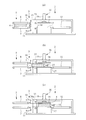
- FIG. 4A is an enlarged side view showing the state of FIG. 3B
- FIG. 4B is a view showing a state in which the product 4 is sandwiched between the upper film 10 and the lower film 11.
- FIG.4 (A) is an enlarged side view which shows the state of Fig.4 (a), (b) is a front view which shows the sealing device which abbreviate
- (A) is an enlarged plan view which shows the state of Fig.4 (a), (b) is a figure which shows the state of the product and film after a side seal.
- (A) is an enlarged plan view which shows the state of FIG.4 (b), (b) is a perspective view which shows the package body manufactured. It is a side view which shows suitable 2nd embodiment of the packaging machine which concerns on this invention. It is a front view which shows suitable 2nd embodiment of the packaging machine which concerns on this invention. It is a front view of the side seal device which shows the suitable modification of the packaging machine concerning the present invention. It is a front view of the side seal device which shows the suitable modification of the packaging machine concerning the present invention.
- the packaging machine 1 includes a packaging machine body 2, a film supply device 3, and a product supply device 5.
- the film supply device 3 is disposed on the upstream side of the packaging machine body 2 and supplies a packaging film to the packaging machine body 2.
- the product supply device 5 is arranged on the upstream side of the packaging machine body 2 and supplies the product 4 to the packaging machine body 2.
- the product 4 of the present invention has elasticity.
- the product 4 is described as having a flat rectangular shape, but the present invention is not limited to this.
- the product 4 when the product 4 is sandwiched and compressed from above and below, the product 4 is elastically deformed and crushed to reduce the thickness, but when the sandwiching force is released, the product 4 expands due to the elastic restoring force.
- the product supply device 5 includes a lower transfer conveyor 7 and an upper transfer conveyor 8.
- the lower conveyance conveyor 7 has a conveyance surface installed in a horizontal plane, and conveys the product 4 placed on the conveyance surface toward the front.
- the upper conveyor 8 has a belt surface that can rotate forward and backward around the front side in the traveling direction. Specifically, as shown in FIG. 1 and the like, the upstream side is lifted up, and the belt surface is placed in a horizontal state as shown in FIG. Transition between the operation positions to be arranged.
- the separation distance between the upper transport conveyor 8 and the lower transport conveyor 7 at the upstream end on the carry-in side is set to be longer than the height of the product 4.
- the upper conveyance conveyor 8 when the upper conveyance conveyor 8 is set at the standby position, the carry-in entrance is greatly opened, and the product 4 can be smoothly set on the lower conveyance conveyor 7. If the upper conveyor 8 is moved to the operating position while the product 4 is placed on the lower conveyor 7, the product 4 is sandwiched between the lower conveyor 7 and the upper conveyor 8, and the state When the lower conveyor 7 and the upper conveyor 8 are rotationally driven, the sandwiched product 4 receives a forward conveying force.
- the upper film 10 and the lower film 11 are used as the packaging film for storing the product 4 used in this embodiment.
- the film supply device 3 supplies the upper film 10 and the lower film 11 to the product 4 so as to be sandwiched from above and below.
- the film supply device 3 rotatably holds the original fabric roll at a predetermined upper position and a predetermined lower position of the product supply device 5.
- the film supply device 3 includes a plurality of rollers 12 that regulate the film conveyance path, and is continuously drawn from the upper film 10 that is continuously drawn from the upper original roll and the lower original roll.
- the lower film 11 is passed over the rollers 12 and the respective leading ends thereof are guided near the downstream end of the product supply device 5.
- the ends of the upper film 10 and the lower film 11 are sealed and joined. As will be described later, this seal is a top seal portion formed in a top seal process performed in manufacturing the previous package.
- the upper film 10 and the lower film 11 are arranged so as to block the conveyance path in front of the product carried out from the product supply device 5. Therefore, when the product 4 is carried out from the product supply device 5, the front end surface of the product 4 comes into contact with the upper film 10 and the lower film 11. When the product 4 further moves forward, the upper film 10 and the lower film 11 are urged by the product 4 and pulled forward in the traveling direction. Further, although not shown in the drawing, the film supply device 3 prevents the upper film 10 and the lower film 11 to be drawn from being urged so that a certain tension is applied, and prevents the film from being loosened by being drawn more than necessary. Equipped with a dancer roller and brake mechanism.
- the seal portion 36 of the upper film 10 and the lower film 11 is gripped by the first clamp 15 and moved forward in the traveling direction by the first clamp 15.
- the product 4 is moved forward together with the upper film 10 and the lower film 11 and moved to the compression / seal work location of the packaging machine body 2.
- the first clamp 15 can be adjusted in the vertical direction according to the product height.
- the packaging machine main body 2 includes a press device 16 at a compression / seal work location, and the press device 16 includes a press lower plate 17, a press upper plate 18, a cylinder 19 and the like.
- the press lower plate 17 is fixedly installed at a predetermined height.
- the predetermined height is, for example, substantially matched with the transport surface of the lower transport conveyor 7.
- the tip of the cylinder rod of the cylinder 19 is connected to the upper surface of the press upper plate 18 and moves up and down following the reciprocation of the cylinder 19.
- the separation distance between the press upper plate 18 and the press lower plate 17 becomes longer than the height of the product 4, and when the press upper plate 18 moves downward, the press lower plate 17 and the press The product 4 is compressed between the upper plate 18.
- lower film restraining portions 20 that stand upward are provided on both side edges of the upper surface of the press lower plate 17 in the traveling direction.
- upper side film holding portions 21 that hang downward are provided on both side edges of the lower surface of the press upper plate 18 in the traveling direction.
- the lower film holding portion 20 and the upper film holding portion 21 are arranged at positions facing each other in the vertical direction, and when the press upper plate 18 moves downward, the upper film holding portion 21 also moves downward together with the press upper plate 18, When the plate 18 reaches the lowered position, the upper film holding portion 21 and the lower film holding portion 20 come into contact with each other.
- the lateral widths of the upper press plate 18 and the lower press plate 17 are set to be shorter than the lateral widths of the upper film 10 and the lower film 11.
- both side edges of the upper film 10 and the lower film 11 protrude to the outside while the product 4 is compressed by the press device 16.
- part is pinched
- both side edges of the upper film 10 and the lower film 11 protrude further outward from the upper film holding portion 21 and the lower film holding portion 20.
- the side edges of the upper film 10 and the lower film 11 are close to each other and in contact with each other. And even if the thickness of the product in the state compressed by the press means is thick, it can seal reliably. Therefore, as shown in FIG.9 (b), the length L1 from the edge part of a product to the edge part of the upper film 10 and the lower film 11 can be shortened, and a package can be manufactured at low cost. . In addition, since both side edges of the film projecting to the outside maintain a taut state, as shown in FIG. 9B, even if the length L2 of the packaging bag 37 is long, the film is securely sealed. can do.
- suppressing part 21 is connected with the press upper board 18, and goes up and down integrally.
- a drive source for raising and lowering the upper film holding portion 21 is also used by the cylinder 19 of the press device 16.
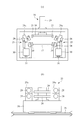
- side seal devices 25 are arranged on the outer sides of both sides of the press device 16, respectively. As shown in FIG. 2B and the like, the side seal device 25 is for heat-sealing both side edges of the upper film 10 and the lower film 11.
- the side seal device 25 includes a pair of bar sealers 26 that sandwich the films from above and below, a pair of upper and lower nip rollers 28 disposed on both front and rear sides of the bar sealer 26, and a pair of upper and lower press rollers 29.
- the nip roller 28 is disposed in front of the film in the traveling direction (in other words, in the forward direction of the side seal device 25), and the press roller 29 is disposed in the rear of the film in the traveling direction (in other words, behind the side seal device 25 in the traveling direction). Deploy. In addition, you may arrange
- the nip roller 28 is made of rubber and sandwiches both side edges of the upper film 10 and the lower film 11 with a predetermined pressure.
- the bar sealer 26 is adjacent to both side edges of the upper film 10 and the lower film 11 and heats the film portion.
- the press roller 29 pressurizes both side edges of the upper film 10 and the lower film 11 heated by the bar sealer 26 with a predetermined pressure, and heat-seals the film portion.
- the pair of upper and lower bar sealers 26, the nip roller 28, and the press roller 29 are configured to be openable and closable, and transition between a standby position separated from each other and an operating position where the upper film 10 and the lower film 11 can be sandwiched by approaching each other. .
- the pair of upper and lower bar sealers 26 move up and down to approach and move away from each other, and the upper film 10 and the lower film 11 passing between the standby positions where the opposing seal surfaces are separated and the seal surfaces are close to each other. Transition between operating positions to heat.
- the support plate 28a to which the upper nip roller 28 is attached rotates in the forward and reverse directions with the lower end edge as the rotation center, and in the standby position, as shown in FIGS. 2 (a), 5 (a), etc. It inclines so that the upper side of 28a may open outside.
- the rotating shaft of the upper nip roller 28 is tilted upward integrally with the support plate 28a, and the upper nip roller 28 and the lower rotating shaft are separated from the horizontal nip roller 28 (FIGS. 2 and 5). Etc.). Further, at the operating position, as shown in FIG.
- the support plate 28a stands up, and the rotation axis of the upper nip roller 28 becomes horizontal with the support plate 28a, so that the upper and lower nip rollers 28 are Contact (see FIG. 7 etc.).
- a pair of upper and lower bar sealers 26, a nip roller 28, and a press roller 29 are installed on a movable table 30.
- the moving table 30 is linked to a guide rail 31 arranged along the film conveyance direction.
- the guide rail 31 is formed over the entire length of the packaging machine body 2.
- a top seal device 33 is disposed upstream of the press device 16.
- the top seal device 33 includes a pair of upper and lower top sealers 34.
- the top sealer 34 moves up and down, and the seal surfaces of the top sealer 34 approach and separate from each other. Further, a cutter is built in the top sealer 34 to cut the seal portion.
- a second clamp 35 is provided on the downstream side of the press device 16 as shown in FIG.
- the second clamp 35 moves in a section from the vicinity of the press device 16 to the vicinity of the downstream side of the carry-out conveyor 32.
- the second clamp 35 can be adjusted in the vertical direction according to the thickness of the compressed product 4.
- the product 4 is set on the lower transport conveyor 7 in a state where the upper transport conveyor 8 is in the downwardly inclined standby position and the carry-in entrance side is open.
- the upper conveyor 8 shifts the belt surface to the upper horizontal operating position and sandwiches the product 4 from above and below.
- the product 4 may be compressed by the upper conveyor 8 and the lower conveyor 7.
- the separation distance between the upper conveyor 8 and the lower conveyor 7 can be set to 1/10 to 1/2 of the height of the product 4.
- the 1st clamp 15 is located in the vicinity of the seal
- the press upper plate 18 of the press device 16 is located at the raised position and is located above the upper surface of the product 4.
- the upper transport conveyor 8 and the lower transport conveyor 7 are rotationally driven to transport the product 4 so that the front end surfaces are brought into contact with the upper film 10 and the lower film 11, and the product 4 is moved to the packaging machine body 2 side together with the both films.
- the first clamp 15 is closed to grip the seal portion 36, and the first clamp 15 is moved into the packaging machine body 2.
- the 1st clamp 15 pulls out the product 4 with the upper film 10 and the lower film 11, and these films and the product 4 move forward within the press apparatus 16 (refer FIG.3 (b)).
- the product 4, the upper film 10 and the lower film 11 moving in the press device 16 are in a state where the upper and lower sides of the product 4 are wrapped by the upper film 10 and the lower film 11 as shown in FIG.
- the both side edges 10a and 11a are not sealed and overlap with each other, and become a sealed portion 36 where the front end edges are joined.
- predetermined positions of the seal portion 36 in this embodiment, two locations in the vicinity of both side edges (see FIG. 6)) are gripped by the first clamp 15.
- the packaging machine 1 drives the press device 16 and compresses the product 4 in a state where the product 4 sandwiched between the upper film 10 and the lower film 11 from above and below is placed at a fixed position. That is, as shown in FIG. 4A, FIG. 7A, etc., the press upper plate 18 moves downward to compress the product 4 together with the upper film 10 and the lower film 11. Moreover, as shown to Fig.7 (a), while the side edge 10a of the upper film 10 and the side edge 11a of the lower film 11 are hold
- the pair of upper and lower bar sealers 26 of the side seal device 25 are close to the side edges 10a and 11a of the film, and the nip roller 28 and the press roller 29 protrude outside the upper film holding portion 21 and the lower film holding portion 20.
- the side edges 10a and 11a of the film are sandwiched (see FIG. 7 etc.).
- the moving table 30 moves forward in the film traveling direction (see FIG. 8A and the like).
- the pair of upper and lower bar sealers 26, the nip roller 28, and the press roller 29 are sealed while moving along the side edges 10a and 11a while sandwiching the side edges 10a and 11a.
- the top seal device 33 is driven, and the pair of top sealers 34 move close to each other to sandwich the upper film 10 and the lower film 11 to form the top seal portion 36, and then the top seal portion 36 is divided into two. Cut (see FIG. 4B, etc.).
- the press upper plate 18 is positioned at the lowered position, and the product 4 remains in a compressed state.
- the compressed state is maintained until the product is sealed.
- the packaging body 38 in the compressed state can be manufactured (see FIG. 9B, etc.).
- the packaging machine 1 performs an unloading process of the package 38.
- the second clamp 35 holds the seal portion 36 as shown in FIG.
- the press upper plate 18 moves upward, and the second clamp 35 moves along the transport direction of the carry-out conveyor 32.
- the package 38 is pulled out from the press device 16 and moves to the carry-out conveyor 32 side (see FIG. 4C and the like).
- the carry-out conveyor 32 is rotationally driven with the movement of the second clamp 35, for example, and assists the withdrawal of the package 38 by the second clamp 35. Thereafter, the carry-out conveyor 32 is driven and the package 38 is carried out.
- the top seal device 33 is provided and both the front and rear sides in the film traveling direction are sealed.
- the present invention is not limited to this, and one or both top seals are not performed. It is good also as the state which both opened.
- the top seal device 33 is fixedly installed.
- a press sealer may be moved, and may be a mobile sealer that seals while moving following the device.
- the total length of the top sealer 34 is longer than the film width, and the top sealer 34 sandwiches the film at one time and seals the lateral direction of the film, but the present invention is not limited to this. Sealing may be performed while moving in the width direction.
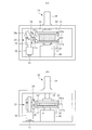
- 10 and 11 show a second embodiment of the present invention.
- a sheet-like film for each sheet is used instead of a continuous film.
- one side seal device 25 is installed on one side, and both side edges are sealed by the one side seal device 25.
- the lower press plate 17 is attached to the rotary table 40 as shown in FIG. Thereby, the press lower plate 17 rotates in a horizontal plane.
- the press upper plate 18 is supported so as to be rotatable with respect to the cylinder 19.
- symbol is attached
- a sheet-like lower film 11 ′, a product 4, and a sheet-like upper film 10 ′ are placed on the lower press plate 17 in this order (see FIG. 10A).
- the press upper plate 18 moves downward to compress the product 4 (see FIG. 10B).
- the side edges 10 ′ a and 11 ′ a of the film are sandwiched and held by the upper film holding portion 21 and the lower film holding portion 20 and protrude outward.
- the side edges 10'a and 11'a of the film are two opposite sides of the four sides of the lower film 11 'and the upper film 10' in this embodiment.
- the press upper plate 18 and the press lower plate 17 compress the product 4 and hold the side edges 10'a and 11'a of the film.
- the moving table 30 of the side seal device 25 moves along the guide rail 31. Accordingly, a pair of upper and lower bar sealers 26, a nip roller 28, and a press roller 29 move while sandwiching the side edges 10'a and 11'a of the film to seal the side edges 10'a and 11'a.
- the side seal device 25 since the side seal device 25 is provided on one side, a side seal is formed on one side edge in the sealing process.
- the side seal device 25 moves backward with the pair of upper and lower bar sealers 26, the nip roller 28, and the press roller 29 opened, and returns to the position shown in FIG.
- the rotary table 40 is driven to rotate the press lower plate 17 by 180 degrees.
- the press upper plate 18 is positioned at the lowered position and compresses the product 4.
- the product 4 and thus the press upper plate 18 also rotate 180 degrees.
- the other unsealed side edges 10'a and 11'a are located on the side seal device 25 side. Therefore, the moving base 30 moves forward in the same manner as described above, and side seal portions are formed on the other side edges 10'a and 11'a.
- the side edges 10'a and 11'a of the film can be side-sealed in a state where the product 4 is compressed.
- the packaging in a state where the other two sides are opened in a state in which both side edges are side-sealed and the product is wound in a cylindrical shape Become a body.
- the turntable 40 is rotated 180 °, and side sealing is performed with respect to two opposite sides of the periphery of the film.
- the present invention is not limited to this, for example, every 90 °. You may make it rotate. If it does in this way, a sealing process can be performed using the side seal apparatus 25 with respect to all four sides of the periphery of a film.
- the upper film holding portion 20 and the lower film holding portion 21 are preferably provided on the four sides of the press lower plate 17 and the press upper plate 18.
- a top seal device may be arranged as in the first embodiment.
- the two adjacent sides are sealed by the top seal device and the side seal device 25 in the first sealing process, and the remaining two sides are sealed in the second sealing process performed by rotating 180 °. it can.
- the side seal can be moved by moving the side seal device starting from the top seal side or the already sealed side as a starting point. Can be suppressed.
- the side seal device 25 is sealed while continuously moving, but the present invention is not limited to this.
- the side seal device 45 shown in FIG. It is also possible to use a seal by repeatedly contacting and separating the bar sealer 46 against the film while moving intermittently, and heating and pressurizing in multiple stages while sequentially changing the sealing position.
- the bar sealer 46 of the side seal device 45 is for sandwiching the film and heating and pressurizing it.
- a side seal device 47 may be used in which a film is sandwiched between the nip roller 48 and the heated press roller 49 shown in FIG.
- the means for heating and pressurizing the film is not limited to using a heating plate, and for example, a sealing method using ultrasonic waves may be used.
- a packaging apparatus and a packaging method for manufacturing a four-sided sealed package in which a product is sandwiched between two films and four sides are sealed have been described, but the present invention is not limited thereto.
- an unsealed part may be provided in one side and may be provided in two or more sides.
- the side seal device can be configured to be able to seal in both reciprocating directions. For example, if the nip roller is changed to a press roller so that the press roller is arranged on both sides of the bar sealer, the upper and lower surfaces heated by the bar sealer can be moved in either the forward direction or the backward direction. The film can be pressed and adhered with a press roller.
Landscapes
- Engineering & Computer Science (AREA)
- Mechanical Engineering (AREA)
- Physics & Mathematics (AREA)
- Fluid Mechanics (AREA)
- Basic Packing Technique (AREA)
Abstract
製品の寸法形状や弾力性などの材質に関係なく、圧縮した状態の製品を収納した包装体を製造する包装機を提供する。上フィルム(10)と下フィルム(11)で挟んだ製品(4)を定位置で圧縮状態にするプレス装置(16)と、プレス装置(16)で圧縮している状態で外部に露出するフィルムの側縁(10a,1a)を挟み込んでシールするサイドシール装置(25)を備える。サイドシール装置(25)は、移動台(30)の上に移動方向に沿って順にニップローラ(28),バーシーラ(26),プレスローラ(29)を備える。移動台(30)は、ガイドレール(31)に沿って移動し、これによりバーシーラ(26)等はフィルムの側縁に沿って移動しながらシールする。
Description
本発明は、包装機及び包装方法に関するもので、より具体的には、製品を圧縮した状態のまま包装する技術に関する。
製品を包装フィルムで包装するに際し、当該製品を圧縮状態で収納し包装フィルムの所定部位をシールして製造される包装体がある。かかる包装体を製造するには、例えば、一辺が開口した袋体に対し、人手により圧縮した製品を袋詰めし、次いで開口した一辺をシールして密封した包装体を製造する。係る人手による袋詰め作業では、単位時間あたりの製造個数をあまり多くすることができないという課題がある。また、人手による包装方法では、製品の全体をきれいに圧縮した状態で袋体に挿入することが困難となる。また、そのように人手で袋詰めするのではなく、包装機により自動的に圧縮状態の物品を包装フィルムで包み込むものがある(特許文献1)。
例えば包装フィルム内に圧縮状態の物品を供給し、係る物品を収納する包装フィルムの所定位置をシール・カットして包装体を製造する包装機は、人手により製造するものに比べると生産数を向上させることができる。この方法は、例えば、スポンジのように比較的弾力性が弱く、比較的小さい力で圧縮でき、圧縮状態を保持できる物品に適用できる。しかし、物品が、例えば弾力性が強かったり、弾性復元力が大きかったりすると、物品を大きく圧縮した状態で包装することができず、最終的な包装体の高さがかさみ、薄くできないおそれがある。
また、包装フィルムの進行方向に沿って物品の寸法が大きい場合、人手あるいは機械のいずれも所望の圧縮した状態でフィルムを供給することが煩雑あるいは困難となる。
上述した課題を解決するために、本発明の包装機は、(1)上下からフィルムで挟んだ製品を定位置で圧縮状態にするプレス手段と、前記プレス手段で圧縮している状態で外部に露出する上下の前記フィルムの側縁を接着するシール手段とを備え、前記シール手段は、前記フィルムの前記側縁に沿って移動しながら接着するように構成した。上下からフィルムで挟むとは、別々のフィルムで製品を挟む場合や、一枚のフィルムを折り曲げて製品を挟み込む場合など各種の態様がある。また、フィルムの側縁とは、例えば、第一実施形態のように帯状のフィルムを用い、連続して供給して製品を挟み、フィルムの進行方向と横方向にカットして帯状フィルムから分離して個々の包装体を包装するような場合は、帯状フィルムのサイドとなる。また、第二実施形態のように包装体毎のシート状のフィルムを用いる場合、フィルムの周縁が側縁となる。
本発明は、上下からフィルムで挟んだ製品を定位置に置いた状態で、プレス手段で圧縮するため、例えば、製品を簡単にフィルム内にセットすることができるとともに、確実に製品を圧縮することができる。そして、本発明は、係る圧縮した状態でフィルムの側縁をシール手段で接着するため、弾力性が強い製品であっても接着処理中はプレス手段で圧縮した状態を保持しているので、例えば接着処理時に圧縮した製品が元に戻ろうとして上下に位置するフィルムを引き離す方向に付勢されることを抑制でき、シール手段で確実に接着することができる。その他に、寸法の変更にもシール手段の移動距離を変更するだけで容易に対応をすることができる。
(2)前記シール手段により接着する際に、前記プレス手段で圧縮している状態で外部に露出し、前記シール手段により接着する前記フィルムの側縁よりも内側に位置するフィルム部位を上下から挟み込んで固定するフィルム抑え機構を備えるとよい。このようにすると、フィルムの側縁がフィルム抑え機構で固定されるので、上下のフィルムの側縁同士が近接・接触することになり、プレス手段で圧縮している状態の製品の厚みが厚い場合であっても、確実に接着することができてシール状態が安定する。
(3)前記シール手段は、上下の前記フィルムを加熱するシーラの進行方向後方にプレスローラを配置し、前記プレスローラにより前記フィルムを加圧することで接着するように構成すると良い。このようにすると、短時間で確実にシールすることができるため、生産性に優れる。
(4)前記シール手段は、ヒーターを備えたプレスローラにより前記フィルムを加圧加熱することで接着するように構成してもよい。このようにすることで、短時間で接着することができるため、生産性に優れる。
(5)前記シール手段は、間欠的に移動しながら上下の前記フィルムを多段階に加圧加熱することで接着するように構成しても良い。このようにすると、安定して確実にフィルム同士をシールすることができる。
(6)本発明に係る包装方法は、上下からフィルムで挟んだ製品を定位置で圧縮し、その圧縮している状態で外部に露出する上下の前記フィルムの側縁をシール手段で挟み込むとともに、そのシール手段を前記側縁に沿って移動して前記側縁を接着するようにした。
(7)前記圧縮している状態で外部に露出し、前記シール手段により接着する前記フィルムの側縁よりも内側に位置するフィルム部位を上下から挟み込んで固定した状態で前記シール手段により接着を行うとよい。
本発明によれば、製品の寸法形状や弾力性などの材質に関係なく、高い圧縮率で圧縮された製品を収納した包装体を製造することができる。特に本発明の包装機および包装方法は、弾性の大きい製品を包装する場合に好適である。
以下、本発明の第一実施形態について図面に基づき、詳細に説明する。なお、本発明は、これに限定されて解釈されるものではなく、本発明の範囲を逸脱しない限りにおいて、当業者の知識に基づいて、種々の変更、修正、改良を加え得るものである。
図1~図9は、本発明に係る包装機の第一実施形態を示している。本実施形態の包装機1は、包装機本体2と、フィルム供給装置3と、製品供給装置5を備える。フィルム供給装置3は、包装機本体2の上流側に配置され、包装機本体2に包装フィルムを供給する。製品供給装置5は、包装機本体2の上流側に配置され、包装機本体2に製品4を供給する。
本発明の製品4は、弾性を有するものである。第一実施形態では、製品4を外形が偏平な矩形状であるものとして説明するが、これに限定されるものではない。例えば製品4を上下から挟み込んで圧縮すると、製品4は弾性変形して押しつぶされて厚みが薄くなるが、挟み込む力を解除すると弾性復元力により膨らむ。
製品供給装置5は、下側搬送コンベア7と、上側搬送コンベア8を備える。下側搬送コンベア7は、搬送面が水平面内に設置され、搬送面上に置かれた製品4を前方に向けて搬送する。上側搬送コンベア8は、進行方向前方側を中心にベルト面が正逆回転可能となる。具体的には、図1等に示すように上流側が持ち上がり進行方向に対して下方傾斜状にベルト面が配置される待機位置と、図3(a)等に示すようにベルト面が水平状態に配置される動作位置との間を遷移する。上側搬送コンベア8が待機位置にあるとき、搬入側となる上流端における上側搬送コンベア8と下側搬送コンベア7との離反距離は、製品4の高さよりも長くなるように設定している。これにより、上側搬送コンベア8を待機位置にセットすると、搬入口が大きく開き、製品4を下側搬送コンベア7上にスムーズにセットすることができる。製品4を下側搬送コンベア7上に置いた状態で上側搬送コンベア8を動作位置に遷移させると、下側搬送コンベア7と上側搬送コンベア8との間で製品4を挟み込むことになり、その状態で下側搬送コンベア7と上側搬送コンベア8を回転駆動すると、挟まれた製品4は前方への搬送力を受ける。
本実施形態で用いる製品4を収納する包装フィルムは、上フィルム10と下フィルム11を用いる。フィルム供給装置3は、それら上フィルム10と下フィルム11を、製品4に上下から挟み込み可能に供給する。具体的には、フィルム供給装置3は、図示省略するが製品供給装置5の上方所定位置と下方所定位置にそれぞれ原反ロールを回転可能に保持する。フィルム供給装置3は、フィルムの搬送経路を規制する複数のローラ12を備え、上側の原反ロールから連続して引き出された上フィルム10と、下側の原反ロールから連続して引き出された下フィルム11を、それぞれローラ12に掛け渡し、それぞれの先端を製品供給装置5の下流側端近傍に導く。上フィルム10と下フィルム11の先端同士は、シールされて接合される。このシールは、後述するように一つ前の包装体の製造に際し行ったトップシール処理に形成されたトップシール部である。
これにより、上フィルム10と下フィルム11とは、製品供給装置5から搬出される製品の前方において搬送経路を遮る様に配置される。よって、製品供給装置5から製品4が搬出されてくると、製品4の前端面が上フィルム10,下フィルム11に接触する。そして、製品4がさらに前進移動すると、上フィルム10と下フィルム11は、製品4に付勢されて進行方向前方に引き出される。また、フィルム供給装置3は、図示省略するが、引き出される上フィルム10や下フィルム11に一定のテンションがかかるように付勢するテンションローラや、必要以上に引き出されてフィルムが弛むのを防止するためのダンサーローラーやブレーキ機構を備える。
さらに、製品4の前端が下側搬送コンベア7,上側搬送コンベア8の前端より先に至り、さらに搬送が進むと、下側搬送コンベア7,上側搬送コンベア8からの搬送力から徐々に弱まり、スムーズな搬送が行えなくなる。そこで、本実施形態では、図3(b)や図6に示すように、上フィルム10と下フィルム11のシール部位36を第一クランプ15で把持し、第一クランプ15にて進行方向前方に引っ張り出すように付勢し、上フィルム10と下フィルム11とともに製品4を前進移動し、包装機本体2の圧縮・シール作業箇所に移動する。第一クランプ15は製品高さに応じて上下方向の位置調整が可能になっている。
包装機本体2は、圧縮・シール作業箇所に、プレス装置16を備える、プレス装置16は、プレス下板17と、プレス上板18と、シリンダ19等を備える。プレス下板17は、所定の高さに固定設置される。所定の高さは、例えば、下側搬送コンベア7の搬送面とほぼ一致させる。このようにすることで、製品供給装置5から搬出された製品4は、その上下が上フィルム10と下フィルム11で挟み込まれた状態でプレス下板17上の定位置にスムーズに位置する。
一方、プレス上板18は、その上面にシリンダ19のシリンダロッドの先端が連結され、シリンダ19の往復動作に追従して昇降する。プレス上板18が上昇位置にあるとき、プレス上板18とプレス下板17の間の離反距離は、製品4の高さよりも長くなり、プレス上板18が下降移動するとプレス下板17とプレス上板18との間で製品4を圧縮する。
図2(a)等に示すように、プレス下板17の上面の進行方向両側縁には、上方に向けて起立する下側フィルム抑え部20を設ける。また、プレス上板18の下面の進行方向両側縁には、下方に向けて垂下する上側フィルム抑え部21を設ける。下側フィルム抑え部20と上側フィルム抑え部21は、上下方向で対向する位置に配置され、プレス上板18が下降移動すると、それと一体となって上側フィルム抑え部21も下降移動し、プレス上板18が下降位置に至ると、上側フィルム抑え部21と下側フィルム抑え部20は接触する。
プレス上板18,プレス下板17の横幅は、上フィルム10,下フィルム11の横幅よりも短い設定とする。これにより、例えば図5,図7等に示すように、プレス装置16で製品4を圧縮している状態で上フィルム10と下フィルム11の両側縁は外部に突出する。そして、その突出したフィルム部位の所定領域は、上側フィルム抑え部21と下側フィルム抑え部20に挟まれて保持される。そして、係る保持された状態において、上フィルム10と下フィルム11の両側縁は、上側フィルム抑え部21と下側フィルム抑え部20のさらに外側に突出した状態となる。上フィルム10と下フィルム11の両側縁近傍部位が上側フィルム抑え部21と下側フィルム抑え部20にて挟み込まれて保持されるため、上フィルム10と下フィルム11の側縁同士が近接・接触し、プレス手段で圧縮している状態の製品の厚みが厚い場合であっても、確実にシールすることができる。そのため、図9(b)に示すように、製品の端部から上フィルム10と下フィルム11の端部までの長さL1を短くすることができ、低コストで包装体を製造することができる。また、その外側に突出したフィルムの両側縁は、ぴんと張った状態を維持するため、図9(b)に示すように、包装袋37の長さL2が長い場合であっても、確実にシールすることができる。
また、本実施形態では、上側フィルム抑え部21は、プレス上板18に連結され、一体になって昇降する。上側フィルム抑え部21を昇降させる駆動源は、プレス装置16のシリンダ19で兼用している。
図2(a)等に示すように、プレス装置16の両サイドの外側には、それぞれサイドシール装置25を配置する。図2(b)等に示すように、サイドシール装置25は、上フィルム10と下フィルム11の両側縁を熱シールするためのものである。サイドシール装置25は、それらフィルムを上下から挟み込む一対のバーシーラ26と、バーシーラ26の前後両側にそれぞれ配置された上下一対のニップローラ28と、上下一対のプレスローラ29を備える。ニップローラ28は、フィルムの進行方向前方(換言すればサイドシール装置25の進行方向前方)に配置し、プレスローラ29は、フィルムの進行方向後方(換言すればサイドシール装置25の進行方向後方)に配置する。なお、プレスローラ29は、フィルムの進行方向前方に配置してもよい。こうすると、サイドシール装置25はバックする際にも上下フィルム10、11を加圧し接着することができるようになり、サイドシール装置25の終端の停止位置において、バーシーラ26で加熱されている未接着のフィルム部位を接着できる機能を付加することができる。
ニップローラ28は、ゴム製であり、上フィルム10と下フィルム11の両側縁を所定の圧力で挟み込む。バーシーラ26は、上フィルム10と下フィルム11の両側縁に近接し、フィルム部位を加熱する。プレスローラ29は、バーシーラ26で加熱された上フィルム10と下フィルム11の両側縁を所定の圧力で加圧し、当該フィルム部位を熱シールする。
上下一対のバーシーラ26,ニップローラ28,プレスローラ29は、開閉可能に構成され、互い離反した待機位置と、互いに接近して上フィルム10と下フィルム11を挟み込み可能な動作位置との間で遷移する。具体的には、上下一対のバーシーラ26は、昇降移動して互いに接近離反し,対向するシール面が離れた待機位置と、シール面どうしが接近してその間を通る上フィルム10と下フィルム11を加熱する動作位置との間で遷移する。上下一対のニップローラ28は、上側のニップローラ28を取り付ける支持板28aが下端縁を回転中心に正逆回転し、待機位置では、図2(a),図5(a)等に示すように支持板28aの上側が外側に開くように傾斜する。これにより、支持板28aと一体になって上側のニップローラ28の回転軸が上向きに傾斜し、当該上側のニップローラ28と下側の回転軸が水平のニップローラ28とが離反する(図2,図5等参照)。また、動作位置では、図7(a)等に示すように、支持板28aは起立し、その支持板28aと一体になって上側のニップローラ28の回転軸も水平になり、上下のニップローラ28が接触する(図7等参照)。プレスローラ29についても同様で、上側のプレスローラ29を取り付ける支持板29aを回転可能に配置することで待機位置と動作位置を採る。
上下一対のバーシーラ26,ニップローラ28,プレスローラ29は、移動台30の上に設置される。移動台30は、フィルムの搬送方向に沿って配置されたガイドレール31に連係される。ガイドレール31は、包装機本体2の全長に渡って形成される。これにより、移動台30ひいてはバーシーラ26,ニップローラ28,プレスローラ29は、プレス装置16に対向するシール作業位置からプレス装置16の下流側に設置された搬出コンベア32に対向する待機位置まで移動する。
さらに、プレス装置16の上流側には、トップシール装置33が配置される。トップシール装置33は、上下一対のトップシーラ34を備える。トップシーラ34は、昇降移動し、互いのシール面が接近離反する。さらに、トップシーラ34内にはカッターが内蔵され、シール部位をカットする。
さらにまた、プレス装置16の下流側には、図4(b)等に示すように、第二クランプ35を備える。第二クランプ35は、プレス装置16の近傍位置から、搬出コンベア32の下流側近傍までの区間を移動する。第二クランプ35は圧縮された製品4の厚みに応じて上下方向の位置調整が可能になっている。
次に上述した構成の包装機1を用いた包装方法の一実施形態を説明する。まず、図1に示すように、上側搬送コンベア8が下方傾斜状の待機位置で、搬入口側が開いた状態において、下側搬送コンベア7の上に製品4をセットする。
次いで、図3(a)に示すように、上側搬送コンベア8は、ベルト面が水平上位の動作位置に遷移し、製品4を上下から挟む。このとき、上側搬送コンベア8と下側搬送コンベア7とで製品4を圧縮するようにしてもよい。例えば、上側搬送コンベア8と下側搬送コンベア7の離反距離を製品4の高さの1/10~1/2とすることができる。また、適宜のタイミングで第一クランプ15は、上フィルム10と下フィルム11を接合したシール部位36の近傍に位置する。また、プレス装置16のプレス上板18は上昇位置に位置し、製品4の上面よりも上方に位置する。
その後、上側搬送コンベア8と下側搬送コンベア7が回転駆動し、製品4を搬送して前端面を上フィルム10と下フィルム11に接触させ、製品4をそれら両フィルムとともに包装機本体2側に向けて搬出・供給する。また、第一クランプ15は閉じてシール部位36を把持するとともに、第一クランプ15が包装機本体2内に移動する。これにより、第一クランプ15は、上フィルム10と下フィルム11とともに製品4を引っ張りだし、それらフィルムと製品4はプレス装置16内を前進移動する(図3(b)参照)。
本実施形態では、製品4とともに上フィルム10と下フィルム11がプレス装置16内を移動する際、サイドシール装置25はプレス装置16に対向するシール作業位置に位置させている。このシール作業位置に位置しているサイドシール装置25のバーシーラ26,ニップローラ28,プレスローラ29は、待機位置に位置する。よって、図5(a)に示すように上フィルム10と下フィルム11の両側縁10a,11aは、ニップローラ28等と非接触の状態となる。また、上述したように、プレス上板18も上昇位置に位置しているため、製品4はスムーズにプレス下板17の上を前進移動し、その際、上フィルム10と下フィルム11の両側縁10a,11aは、上下一対のバーシーラ26,ニップローラ28,プレスローラ29間の空間内を進む。
また、このプレス装置16内を移動する製品4,上フィルム10,下フィルム11は、図5(b)に示すように、製品4の上下が上フィルム10と下フィルム11で包まれた状態で、その両側縁10a,11aはシールされておらず重なった状態であり、前端縁が接合されたシール部位36となる。さらに上述したようにこのシール部位36の所定位置(本実施形態では、両側縁近傍の二カ所(図6参照))が第一クランプ15で把持される。
そして、第一クランプ15により製品4がプレス下板17上の定位置まで引き出されると、第一クランプ15の前進移動が停止し、製品4を定位置に至る(図3(c),図6参照)。また、製品4が定位置に至ると、製品4の全体がプレス下板17上に乗った状態となり、トップシール装置33のトップシーラ34間には、製品4は位置せずに上フィルム10と下フィルム11が存在する。
包装機1は、このように上下から上フィルム10と下フィルム11で挟んだ製品4を定位置に置いた状態で、プレス装置16を駆動し、製品4を圧縮する。つまり、図4(a),図7(a)等に示すように、プレス上板18は下降移動し、製品4を上フィルム10,下フィルム11ごと圧縮する。また、図7(a)に示すように、上フィルム10の側縁10a,下フィルム11の側縁11aは、上側フィルム抑え部21,下側フィルム抑え部20により保持されるとともに、さらにその側縁先端が外側に突出する。
次いで、サイドシール装置25の上下一対のバーシーラ26は、フィルムの側縁10a,11aに近接するとともに、ニップローラ28,プレスローラ29が上側フィルム抑え部21,下側フィルム抑え部20の外側に突出しているフィルムの側縁10a,11aを挟み込む(図7等参照)。その状態で移動台30がフィルム進行方向前方に移動する(図8(a)等参照)。すると、上下一対のバーシーラ26,ニップローラ28,プレスローラ29は、側縁10a,11aを挟み込んだ状態のまま側縁10a,11aに沿って移動しながらシールする。これにより、図8(b)に示すように、上フィルム10の側縁10a,下フィルム11の側縁11aは熱シールされてサイドシール部37が形成される。このサイドシールする際も、プレス上板18は下降位置にいるため、製品4は圧縮状態のままシール処理がなされる。
次に、トップシール装置33が駆動し、一対のトップシーラ34が互いに接近移動して上フィルム10と下フィルム11を挟み込み、トップシール部36を形成した後、トップシール部36を二分するようにカットする(図4(b)等参照)。このトップシール処理をする際も、プレス上板18が下降位置に位置し、製品4は圧縮状態のままとなる。このように、シール処理する間、プレス上板18とプレス下板17の間で製品を圧縮しているため、たとえ製品4が弾力性の強い材料であってもシールするまで圧縮状態が保持され、係る圧縮状態のままの包装体38が製造できる(図9(b)等参照)。
次に包装機1は、包装体38の搬出処理を行う。まず、包装体が製造されたならば、図9(a)に示すように、第二クランプ35がシール部位36を把持する。次いで、プレス上板18が上昇移動するとともに、第二クランプ35が、搬出コンベア32の搬送方向に沿って移動する。これにより、包装体38は、プレス装置16から引き出され、搬出コンベア32側に移行する(図4(c)等参照)。搬出コンベア32は、例えば第二クランプ35の移動に伴い回転駆動し、第二クランプ35による包装体38の引き出しを補助する。以後、搬出コンベア32が駆動し、包装体38を搬出する。
上述した実施形態では、トップシール装置33を設け、フィルム進行方向の前後の両側をシールしたが、本発明はこれに限ることはなく、一方或いは双方のトップシールを行わず、包装体の一方或いは双方が開封した状態としてもよい。
さらに上述した実施形態では、トップシール装置33は固定設置されたが、例えば、サイドシール装置25と同様に、プレス装置が移動し、それに追従して移動しながらシールする移動式シーラとしてもよい。また、上述した実施形態では、トップシーラ34の全長はフィルム幅よりも長くし、トップシーラ34は一度にフィルムを挟み込んでフィルムの横方向をシールしたが、本発明はこれに限ることはなく、幅方向に移動しながらシールするようにしてもよい。
図10,図11は、本発明の第二実施形態を示している。本実施形態では、第一実施形態と相違し、包装フィルムが連続したフィルムではなく一枚毎のシート状のフィルムを用いる。また、サイドシール装置25は、片側に一台設置し、その一台のサイドシール装置25で両側縁をシールするようにした。
具体的には、図10に示すように、プレス下板17を回転テーブル40に取り付ける。これにより、プレス下板17は水平面内で回転する。また、プレス上板18は、シリンダ19に対し回転可能に支持される。なお、上述した第一実施形態の装置と同一・対応する部材については、同一符号を付し、その説明を省略する。
次に上述した構成の包装機1を用いた包装方法の一実施形態を説明する。まず、プレス下板17の上に、一枚のシート状の下フィルム11′,製品4,一枚のシート状の上フィルム10′の順に重ねた状態で置く(図10(a)参照)。次いで、プレス上板18が下降移動し、製品4を圧縮する(図10(b)参照)。このとき、フィルムの側縁10′a,11′aは、上側フィルム抑え部21と下側フィルム抑え部20とにより挟み込まれて保持されるとともに、その外側に突出する。ここで、フィルムの側縁10’a,11’aは、本実施形態では下フィルム11′,上フィルム10′の四辺のうちの対向する二辺としている。
次いで、図10(b)に示すように、プレス上板18とプレス下板17が製品4を圧縮するとともにフィルムの側縁10′a,11′aを保持した状態で、図11(a)から図11(b)に示すようにサイドシール装置25の移動台30がガイドレール31に沿って移動する。これに伴い、上下一対のバーシーラ26,ニップローラ28,プレスローラ29がフィルムの側縁10′a,11′aを挟み込んだ状態で移動し、側縁10′a,11′aをシールする。本実施形態では、サイドシール装置25は片側に設けているため、係るシール処理で一方の側縁についてサイドシールを形成する。係る一方の側縁のシール処理が完了すると、サイドシール装置25は、上下一対のバーシーラ26,ニップローラ28,プレスローラ29を開いた状態で後退移動し、図11(a)の位置に復帰する。
また、回転テーブル40が駆動し、プレス下板17を180度回転する。このとき、プレス上板18は、下降位置に位置して製品4を圧縮している状態であり、プレス下板17の回転を受けて製品4ひいてはプレス上板18も180度回転する。これにより、未シールの他方の側縁10′a,11′aがサイドシール装置25側に位置する。よって、上記と同様に移動台30が前進移動し、他方の側縁10′a,11′aにサイドシール部を形成する。
上記の処理を行うことで、製品4を圧縮した状態でフィルムの両側縁10′a,11′aをサイドシールすることができる。そして、本実施形態では、第一実施形態と相違しトップシール装置を設けていないため、両側縁をサイドシールして製品を筒状に巻いた状態で、他の2辺側が開放した状態の包装体となる。
また、本実施形態では、回転テーブル40が180°回転し、フィルムの周縁のうち対向する二辺に対してサイドシールするようにしたが、本発明はこれに限ることはなく、例えば90°毎に回転するようにしてもよい。このようにすると、フィルムの周縁の4辺全てに対し、サイドシール装置25を用いてシール処理を行うことができる。また、このように4辺全てにサイドシールを施す場合、好ましくは、上側フィルム抑え部20,下側フィルム抑え部21は、プレス下板17,プレス上板18の4辺に設ける。
また、本実施形態の包装機においても、第一実施形態と同様にトップシール装置を配置するとよい。このようにすると、1回目のシール処理でトップシール装置とサイドシール装置25にて隣接する2辺をシールし、180°回転して行う2回目のシール処理で残りの2辺をシールすることができる。また、上記実施形態において、サイドシールをトップシール側又は既にシールされている側を始点としてサイドシール装置を移動させシールを行うこともでき、こうすることで、フィルムのシワの発生を可及的に抑えることができる。
さらにまた、上述した各実施形態並びに変形例では、サイドシール装置25は、連続して移動しながらシールしたが、本発明はこれに限ることはなく、例えば、図12に示すサイドシール装置45を用いて、間欠的に移動しながらフィルムに対してバーシーラ46の接触離反を繰り返し、シール位置を順次変えながら多段階に加熱加圧することによりシールするものでもよい。なお、サイドシール装置45のバーシーラ46は、フィルムを挟み込んで加熱加圧するためのものである。また、図13に示すニップローラ48と加熱したプレスローラ49によりフィルムを挟み込んで移動しながらシールするサイドシール装置47を用いてもよい。フィルムを加熱加圧する手段として加熱板によるものだけではなく例えば、超音波によるシール方法などでも良い。
上述した各実施形態並びに各種の変形例では、2枚のフィルムで製品を挟み込み、4辺をシールする四方シール包装体を製造する包装装置・包装方法について説明したが、本発明はこれに限ることはなく、例えば、1枚のフィルムを折り曲げて製品を挟み込んで所定部位をシールする三方シール包装体を製造する包装装置・包装方法としてもよい。また、各種の包装処理をするに際し、シール部に部分的に未シール部を設けた包装体を製造する包装装置・包装方法としてもよい。また、未シール部は、一辺に設けてもよいし、二辺以上に設けてもよい。サイドシール装置は、往復両方向でシールできるようにすることも可能である。例えば、ニップローラをプレスローラに変更して、バーシーラの両側にプレスローラが配置された構造にすれば、往方向及び復方向のいずれの方向に移動する場合であっても、バーシーラで加熱された上下フィルムをプレスローラで加圧し接着することができる。
1 包装機
2 包装機本体
3 フィルム供給装置
4 製品
5 製品供給装置
10 上フィルム
10a 側縁
10′上フィルム
10′a 側縁
11 下フィルム
11a 側縁
11′下フィルム
11′a 側縁
16 プレス装置
17 プレス下板
18 プレス上板
19 シリンダ
20 下側フィルム抑え部
21 上側フィルム抑え部
25 サイドシール装置
26 バーシーラ
28 ニップローラ
29 プレスローラ
30 移動台
31 ガイドレール
38 包装体
2 包装機本体
3 フィルム供給装置
4 製品
5 製品供給装置
10 上フィルム
10a 側縁
10′上フィルム
10′a 側縁
11 下フィルム
11a 側縁
11′下フィルム
11′a 側縁
16 プレス装置
17 プレス下板
18 プレス上板
19 シリンダ
20 下側フィルム抑え部
21 上側フィルム抑え部
25 サイドシール装置
26 バーシーラ
28 ニップローラ
29 プレスローラ
30 移動台
31 ガイドレール
38 包装体
Claims (7)
- 上下からフィルムで挟んだ製品を定位置で圧縮状態にするプレス手段と、
前記プレス手段で圧縮している状態で外部に露出する上下の前記フィルムの側縁を接着するシール手段と
を備え、
前記シール手段は、前記フィルムの前記側縁に沿って移動しながら接着するように構成したことを特徴とする包装機。 - 前記シール手段により接着する際に、前記プレス手段で圧縮している状態で外部に露出し、前記シール手段により接着する前記フィルムの側縁よりも内側に位置するフィルム部位を上下から挟み込んで固定するフィルム抑え機構を備えることを特徴とする請求項1に記載の包装機。
- 前記シール手段は、上下の前記フィルムを加熱するシーラの進行方向後方にプレスローラを配置し、
前記プレスローラにより、加熱された上下の前記フィルムを加圧することで接着するように構成したことを特徴とする請求項1または2に記載の包装機。 - 前記シール手段は、ヒーターを備えたプレスローラにより上下の前記フィルムを加圧加熱することで接着するように構成したことを特徴とする請求項1または2に記載の包装機。
- 前記シール手段は、間欠的に移動しながら上下の前記フィルムを多段階に加圧加熱することで接着するように構成したことを特徴とする請求項1または2に記載の包装機。
- 上下からフィルムで挟んだ製品を定位置で圧縮し、
その圧縮している状態で外部に露出する上下の前記フィルムの側縁をシール手段で挟み込むとともに、そのシール手段を前記側縁に沿って移動して前記側縁を接着することを特徴とする包装方法。 - 前記圧縮している状態で外部に露出し、前記シール手段により接着する前記フィルムの側縁よりも内側に位置するフィルム部位を上下から挟み込んで固定した状態で、前記シール手段により接着を行うことを特徴とする請求項6に記載の包装方法。
Priority Applications (1)
| Application Number | Priority Date | Filing Date | Title |
|---|---|---|---|
| PCT/JP2015/084526 WO2017098604A1 (ja) | 2015-12-09 | 2015-12-09 | 包装機及び包装方法 |
Applications Claiming Priority (1)
| Application Number | Priority Date | Filing Date | Title |
|---|---|---|---|
| PCT/JP2015/084526 WO2017098604A1 (ja) | 2015-12-09 | 2015-12-09 | 包装機及び包装方法 |
Publications (1)
| Publication Number | Publication Date |
|---|---|
| WO2017098604A1 true WO2017098604A1 (ja) | 2017-06-15 |
Family
ID=59012838
Family Applications (1)
| Application Number | Title | Priority Date | Filing Date |
|---|---|---|---|
| PCT/JP2015/084526 Ceased WO2017098604A1 (ja) | 2015-12-09 | 2015-12-09 | 包装機及び包装方法 |
Country Status (1)
| Country | Link |
|---|---|
| WO (1) | WO2017098604A1 (ja) |
Cited By (3)
| Publication number | Priority date | Publication date | Assignee | Title |
|---|---|---|---|---|
| CN112124666A (zh) * | 2020-10-17 | 2020-12-25 | 湖南亲零嘴食品有限公司 | 基于压合密封包装的素牛排密封装置 |
| CN115520462A (zh) * | 2021-06-25 | 2022-12-27 | 北京星昊医药股份有限公司 | 一种冻干口崩片剂塑封设备 |
| CN115520455A (zh) * | 2022-09-05 | 2022-12-27 | 杭州职业技术学院 | 超声波电缆束连续封装设备 |
Citations (6)
| Publication number | Priority date | Publication date | Assignee | Title |
|---|---|---|---|---|
| JPS5516884B2 (ja) * | 1973-04-12 | 1980-05-07 | ||
| JPS57123701U (ja) * | 1981-01-27 | 1982-08-02 | ||
| WO2005080208A1 (en) * | 2004-02-20 | 2005-09-01 | Rockwool International A/S | Apparatus and method for packaging mineral wool products and a mineral wool package |
| JP2008100730A (ja) * | 2006-10-19 | 2008-05-01 | Omori Mach Co Ltd | ピロー包装機 |
| JP2013199020A (ja) * | 2012-03-23 | 2013-10-03 | Takao Tanaka | 樹脂フィルムのヒートシール装置及びヒートシール方法 |
| JP2014180775A (ja) * | 2013-03-18 | 2014-09-29 | Dainippon Printing Co Ltd | 製袋機および製袋方法 |
-
2015
- 2015-12-09 WO PCT/JP2015/084526 patent/WO2017098604A1/ja not_active Ceased
Patent Citations (6)
| Publication number | Priority date | Publication date | Assignee | Title |
|---|---|---|---|---|
| JPS5516884B2 (ja) * | 1973-04-12 | 1980-05-07 | ||
| JPS57123701U (ja) * | 1981-01-27 | 1982-08-02 | ||
| WO2005080208A1 (en) * | 2004-02-20 | 2005-09-01 | Rockwool International A/S | Apparatus and method for packaging mineral wool products and a mineral wool package |
| JP2008100730A (ja) * | 2006-10-19 | 2008-05-01 | Omori Mach Co Ltd | ピロー包装機 |
| JP2013199020A (ja) * | 2012-03-23 | 2013-10-03 | Takao Tanaka | 樹脂フィルムのヒートシール装置及びヒートシール方法 |
| JP2014180775A (ja) * | 2013-03-18 | 2014-09-29 | Dainippon Printing Co Ltd | 製袋機および製袋方法 |
Cited By (4)
| Publication number | Priority date | Publication date | Assignee | Title |
|---|---|---|---|---|
| CN112124666A (zh) * | 2020-10-17 | 2020-12-25 | 湖南亲零嘴食品有限公司 | 基于压合密封包装的素牛排密封装置 |
| CN115520462A (zh) * | 2021-06-25 | 2022-12-27 | 北京星昊医药股份有限公司 | 一种冻干口崩片剂塑封设备 |
| CN115520455A (zh) * | 2022-09-05 | 2022-12-27 | 杭州职业技术学院 | 超声波电缆束连续封装设备 |
| CN115520455B (zh) * | 2022-09-05 | 2025-11-07 | 杭州职业技术学院 | 超声波电缆束连续封装设备 |
Similar Documents
| Publication | Publication Date | Title |
|---|---|---|
| JP6614572B2 (ja) | 包装機 | |
| CN107848644B (zh) | 将单个或成组的产品包装在包装件中的包装机及其方法 | |
| US8616768B2 (en) | Pleated stand-up packaging pouch, pleated stand-up packaging body, feed roll for pleated stand-up packaging body, and method of manufacturing pleated stand-up packaging body | |
| CN102239043A (zh) | 用于闭合最好为袋式的包装用具的闭合设备 | |
| JPH05262335A (ja) | パッケージフィルムに閉鎖手段を整列装着する方法及び装置 | |
| JP6334283B2 (ja) | 包装機及び包装方法 | |
| WO2017098604A1 (ja) | 包装機及び包装方法 | |
| JP6279455B2 (ja) | 容器の帯巻き装置 | |
| JP3831351B2 (ja) | 包装袋の製造方法および縦型充填包装機 | |
| KR101616933B1 (ko) | 물품 포장 장치 및 이를 이용한 물품 포장 방법 | |
| JP6695675B2 (ja) | センターシール装置 | |
| JP2016141397A (ja) | 包装機 | |
| WO1998054055A1 (en) | Film tuck-in device of packaging apparatus | |
| CN101528548B (zh) | 揭取式包装装置以及用于该装置的夹持装置 | |
| JP6595799B2 (ja) | 包装機 | |
| JP2005119746A (ja) | 包装装置 | |
| JP5635542B2 (ja) | 製袋充填機における袋開封部形成装置 | |
| JP4741636B2 (ja) | 横形製袋充填機におけるエンドシール部のしわ取り装置 | |
| JP2018154388A (ja) | 包装体、製袋袋、包装方法および包装機 | |
| JP6378488B2 (ja) | ピロー包装装置 | |
| JP2017206292A (ja) | パウチの開口装置 | |
| CN114531867B (zh) | 改进的密封装置 | |
| JP2010269810A (ja) | 縦形製袋充填包装機 | |
| JPH06336207A (ja) | サンドイッチ等の軟質被包装物の包装方法および装置 | |
| JP2019038566A (ja) | 押さえ付け装置 |
Legal Events
| Date | Code | Title | Description |
|---|---|---|---|
| 121 | Ep: the epo has been informed by wipo that ep was designated in this application |
Ref document number: 15910220 Country of ref document: EP Kind code of ref document: A1 |
|
| NENP | Non-entry into the national phase |
Ref country code: DE |
|
| 122 | Ep: pct application non-entry in european phase |
Ref document number: 15910220 Country of ref document: EP Kind code of ref document: A1 |
|
| NENP | Non-entry into the national phase |
Ref country code: JP |