WO2017094652A1 - 照明装置 - Google Patents
照明装置 Download PDFInfo
- Publication number
- WO2017094652A1 WO2017094652A1 PCT/JP2016/085140 JP2016085140W WO2017094652A1 WO 2017094652 A1 WO2017094652 A1 WO 2017094652A1 JP 2016085140 W JP2016085140 W JP 2016085140W WO 2017094652 A1 WO2017094652 A1 WO 2017094652A1
- Authority
- WO
- WIPO (PCT)
- Prior art keywords
- light emitting
- unit
- heater
- emitting element
- light source
- Prior art date
- Legal status (The legal status is an assumption and is not a legal conclusion. Google has not performed a legal analysis and makes no representation as to the accuracy of the status listed.)
- Ceased
Links
Images




Classifications
-
- F—MECHANICAL ENGINEERING; LIGHTING; HEATING; WEAPONS; BLASTING
- F21—LIGHTING
- F21L—LIGHTING DEVICES OR SYSTEMS THEREOF, BEING PORTABLE OR SPECIALLY ADAPTED FOR TRANSPORTATION
- F21L14/00—Electric lighting devices without a self-contained power source, e.g. for mains connection
-
- F—MECHANICAL ENGINEERING; LIGHTING; HEATING; WEAPONS; BLASTING
- F17—STORING OR DISTRIBUTING GASES OR LIQUIDS
- F17C—VESSELS FOR CONTAINING OR STORING COMPRESSED, LIQUEFIED OR SOLIDIFIED GASES; FIXED-CAPACITY GAS-HOLDERS; FILLING VESSELS WITH, OR DISCHARGING FROM VESSELS, COMPRESSED, LIQUEFIED, OR SOLIDIFIED GASES
- F17C13/00—Details of vessels or of the filling or discharging of vessels
- F17C13/02—Special adaptations of indicating, measuring, or monitoring equipment
-
- F—MECHANICAL ENGINEERING; LIGHTING; HEATING; WEAPONS; BLASTING
- F21—LIGHTING
- F21V—FUNCTIONAL FEATURES OR DETAILS OF LIGHTING DEVICES OR SYSTEMS THEREOF; STRUCTURAL COMBINATIONS OF LIGHTING DEVICES WITH OTHER ARTICLES, NOT OTHERWISE PROVIDED FOR
- F21V23/00—Arrangement of electric circuit elements in or on lighting devices
-
- F—MECHANICAL ENGINEERING; LIGHTING; HEATING; WEAPONS; BLASTING
- F21—LIGHTING
- F21V—FUNCTIONAL FEATURES OR DETAILS OF LIGHTING DEVICES OR SYSTEMS THEREOF; STRUCTURAL COMBINATIONS OF LIGHTING DEVICES WITH OTHER ARTICLES, NOT OTHERWISE PROVIDED FOR
- F21V29/00—Protecting lighting devices from thermal damage; Cooling or heating arrangements specially adapted for lighting devices or systems
- F21V29/90—Heating arrangements
-
- F—MECHANICAL ENGINEERING; LIGHTING; HEATING; WEAPONS; BLASTING
- F21—LIGHTING
- F21Y—INDEXING SCHEME ASSOCIATED WITH SUBCLASSES F21K, F21L, F21S and F21V, RELATING TO THE FORM OR THE KIND OF THE LIGHT SOURCES OR OF THE COLOUR OF THE LIGHT EMITTED
- F21Y2115/00—Light-generating elements of semiconductor light sources
- F21Y2115/10—Light-emitting diodes [LED]
Definitions
- the present disclosure relates to a lighting device.
- This application claims priority based on Japanese Patent Application No. 2015-234760 for which it applied to Japan on December 1, 2015, and uses the content here.
- Patent Document 1 in order to observe the inside of an LNG (Liquefied Natural Gas) tank, an observation device equipped with an illumination device is used.
- This observation apparatus is provided with a plurality of light sources so that the entire area inside the wide LNG tank can be imaged.
- an observation apparatus is usually placed in the LNG tank through a nozzle having a small inner diameter provided on the ceiling of the LNG tank. For this reason, a plurality of light sources are arranged in the vertical direction of the apparatus in order to prevent the apparatus from becoming large in plan view.
- Patent Documents 2 to 4 also disclose illumination devices.
- Japanese Unexamined Patent Publication No. 9-43030 Japanese Laid-Open Patent Publication No. 3-223599 Japanese Unexamined Patent Publication No. 2012-182152 Japanese Unexamined Patent Publication No. 2011-086602
- LED light source including an LED (light emitting diode)
- the current value that can be flowed becomes small due to the characteristics of the semiconductor, and the illuminance cannot be secured.
- each light-emitting element can be appropriately heated to a temperature at which luminous efficiency is increased. It aims to be.
- a first aspect of the present disclosure is an illumination device that can be immersed in a low-temperature liquefied gas, and includes a base portion and a plurality of light source units installed in the base portion, and each light source unit of the plurality of light source units is And a light-emitting element including a light-emitting diode, a heater that generates heat by power supply, and a thermostat that is installed in a power supply line to the heater and changes an energization state of the heater according to temperature.
- a plurality of light source units including light emitting elements including light emitting diodes are provided, and a heater and a thermostat are installed for each light source unit. For this reason, it is possible to control the temperature for each light source unit, prevent the occurrence of temperature unevenness, and appropriately heat each light emitting element to a temperature at which the light emission efficiency is increased. .
- FIG. 4A It is a perspective view which shows schematic structure of the illuminating device in one Embodiment of this indication. It is a side view of the illumination unit with which the illuminating device in one Embodiment of this indication is provided. It is a longitudinal cross-sectional view of the illumination unit with which the illuminating device in one Embodiment of this indication is provided. It is an enlarged side view including the board
- FIG. 4 is a sectional view taken along the line CC of FIG. 3. It is a wiring diagram showing typically the connection relation in the lighting unit with which the illuminating device in one embodiment of this indication is provided.
- FIG. 1 is a perspective view showing a schematic configuration of a lighting device 1 of the present embodiment.
- the illuminating device 1 of this embodiment is suspended and supported by a cable K, and is lifted and lowered when the cable K is wound or sent out by a winding drum.
- the illuminating device 1 in this embodiment includes a turning unit 2 and an illuminating unit 3.
- the turning unit 2 constitutes an upper part of the lighting device 1 in the present embodiment, and includes a trunk portion 2a, a rotating shaft portion 2b, and a drive mechanism (not shown).
- drum 2a is a substantially cylindrical member which accommodates the drive mechanism etc. which are not shown in figure.
- drum 2a has the connection part 2a1 to which the cable K is connected in an upper end part.
- the rotating shaft portion 2b is provided so as to protrude downward from the lower end portion of the body portion 2a, and is connected to the body portion 2a so as to be able to turn.
- the rotating shaft portion 2b is connected to a drive mechanism housed inside the trunk portion 2a, and is rotatable about the vertical axis with respect to the trunk portion 2a by the drive mechanism.
- the lower end portion of the rotating shaft portion 2b is fixed to the illumination unit 3.
- the lighting unit 3 constitutes a lower part of the lighting device 1 in the present embodiment.
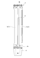
- FIG. 2 is a side view of the lighting unit 3.
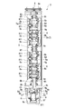
- FIG. 3 is a longitudinal sectional view of the lighting unit 3.
- the illumination unit 3 includes a base part 4, a connector 5, a trunk unit 6 (light source unit), a trunk case 7, a lower end unit 8 (light source unit), and a lower end case. 9 and.
- the base portion 4 is a member that supports the body unit 6, the body case 7, the lower end unit 8, and the lower end case 9, and the upper flange 4 a connected to the turning unit 2 and the lower end unit 8 are fixed. And a lower flange 4b. Two openings 4c in which the body unit 6 is accommodated are formed at the center of the base portion 4 in the vertical direction. Such a base part 4 also functions as a heat sink for preventing overheating of the body unit 6 and the lower end unit 8.
- the connector 5 is provided in the center of the upper flange 4a of the base portion 4 in plan view, and protrudes upward from the upper surface of the upper flange 4a.
- the connector 5 is connected to the turning unit 2 and electrically connects the turning unit 2 and the illumination unit 3.
- Each trunk unit 6 is fixed to the base unit 4 so as to pass through the opening 4 c of the base unit 4.
- the body unit 6 includes a substrate 6a, a light emitting element 6b, a lens unit 6c, a heater 6d, a thermostat 6e, a front cover 6f, a back cover 6g, and a gasket 6h.
- the substrate 6a is a plate member on which the light emitting element 6b, the lens unit 6c, the heater 6d, and the thermostat 6e are mounted, and is fixed to the base portion 4.
- the light emitting element 6b is mounted on the front surface of the substrate 6a.
- the light emitting element 6b includes a light emitting diode (LED) and emits light when power is supplied through a wiring (not shown).
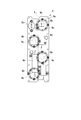
- FIG. 4A is an enlarged side view including the substrate 6a
- FIG. 4B is a front view seen from the direction of arrow A in FIG. 4A
- FIG. 4C is a rear view seen from the direction of arrow B in FIG.
- four light emitting elements 6b are mounted on the substrate 6a. These light emitting elements 6b are arranged along a vertical axis L passing through the center of the substrate 6a, and are alternately arranged on the left and right of the vertical axis L with the vertical axis L as a central axis in the downward direction.
- the lens unit 6c is fixed to the substrate 6a, and is disposed in front of the light emitting element 6b so as to cover the light emitting element 6b.
- the lens unit 6c is provided for each of the light emitting elements 6b. That is, as shown in FIG. 4B, four lens units 6c are mounted on the substrate 6a. These lens units 6c guide the light emitted from the light emitting element 6b toward the front side of the substrate 6a.
- the heater 6d is mounted on the back surface of the substrate 6a.
- the heater 6d generates heat when power is supplied through a wiring (not shown).
- two heaters 6d are mounted on the substrate 6a. These heaters 6d have a long shape along the vertical axis L.
- the heaters 6d are arranged along the vertical axis L.
- One heater 6d is arranged on one side of the vertical axis L, and the other heater 6d is arranged on the other side of the vertical axis L. That is, one heater 6d and the other heater 6d are disposed on the opposite sides with the vertical axis L in between.
- the thermostat 6e is mounted on the back surface of the substrate 6a. This thermostat 6e is installed in the power supply line of the heater 6d, and switches the power supply state to the heater 6d by switching the power supply state of the power supply line. The thermostat 6e switches the energization state between a power supply state where power is supplied to the heater 6d and a disconnected state where power is not supplied to the heater 6d.
- FIG. 5A is a graph showing an example of the relationship between the temperature and the illuminance of the light emitting element 6b used in the present embodiment.
- FIG. 5B is a graph showing the relationship between the temperature of the light emitting element 6b used in this embodiment and the power consumption.
- FIG. 5C is a graph showing the relationship between the power consumption and the illuminance of the light emitting element 6b used in the present embodiment. The graphs shown in FIGS.
- 5A to 5C were obtained by an experiment in which a plate on which the light emitting element 6b and the thermocouple were installed was immersed in liquid nitrogen, and after being brought to a very low temperature, pulled up to return to room temperature.
- the illuminance is normalized with a value when the temperature of the thermocouple is 20 ° C.
- the light emitting element 6b used in this embodiment has the highest illuminance in the vicinity of 0 ° C.
- the power consumption increases as the temperature increases.
- the power consumption has a peak in the vicinity of 25 W, which corresponds to the light emitting element 6b in the vicinity of 0 ° C.
- the light emitting element 6b has the highest luminous efficiency in the vicinity of 0 ° C.
- the switching temperature of the energized state is set so that the ambient temperature becomes 0 ° C. That is, when the ambient temperature is lower than 0 ° C., the thermostat 6e sets the energization state to the heater 6d to the power supply state, and when the ambient temperature is higher than 0 ° C., the thermostat 6e disconnects the energization state to the heater 6d. And
- the energized state is switched based on 0 ° C., the energized state is frequently switched.
- the energized state when the temperature is greatly displaced from 0 ° C.
- the energized state is switched from the power supply state to the disconnected state when the temperature is 20 ° C. or higher, and the energized state is switched from the disconnected state to the power supplied state when it is ⁇ 20 ° C. or lower.
- the front cover 6f is a member that covers the substrate 6a from the front side of the substrate 6a together with the light emitting element 6b and the lens unit 6c, and is fastened to the base portion 4 via the gasket 6h.
- a front cover 6f prevents the outside liquid such as LNG (low temperature liquefied gas) from entering the front cover 6f together with the gasket 6h.
- the front cover 6f has a viewport 6f1 including a transparent member in a region facing the lens unit 6c. That is, the front cover 6f has four viewports 6f1.
- Such a view port 6f1 allows light of the light emitting element 6b emitted from the lens unit 6c to pass through without being blocked.
- the back cover 6g is a member that covers the substrate 6a from the back side of the substrate 6a together with the heater 6d and the thermostat 6e, and is fastened to the base portion 4 via the gasket 6h. Such a back cover 6g prevents external liquid from entering the back cover 6g together with the gasket 6h.
- the gasket 6h is interposed between the front cover 6f and the base portion 4 and between the back cover 6g and the base portion 4, and is inserted into the front cover 6f and the back cover 6g. Prevents ingress of liquid.
- Each of the trunk unit 6 is supported in a posture in which the optical axis of the lens unit 6c is horizontal so that the irradiation direction is horizontal. Further, the two trunk unit 6 are arranged in the vertical direction with the space S therebetween. With such a space S, it is possible to suppress the transmission of heat from each of the trunk unit 6.
- the trunk case 7 is a case that is fixed to the base portion 4 and covers the trunk unit 6.
- a front case 7 a that covers the front side of the trunk unit 6 and a back case 7 b that covers the rear side of the trunk unit 6 are installed as the trunk case 7. These trunk cases 7 protect the trunk unit 6.
- the lower end unit 8 includes a substrate 8a, a light emitting element 8b, a lens unit 8c, a heater 8d, a thermostat 8e, a lower surface cover 8f, a stay 8g, an upper surface plate 8h, and a gasket. 8i.
- the substrate 8a is a plate member on which the light emitting element 8b, the lens unit 8c, the heater 8d, and the thermostat 8e are mounted, and is fixed to the upper surface plate 8h via the stay 8g.
- the light emitting element 8b is mounted on the lower surface of the substrate 8a.
- the light emitting element 8b includes a light emitting diode (LED), and emits light when power is supplied through a wiring (not shown).
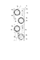
- FIG. 6 is a cross-sectional view taken along the line CC of FIG.
- one light emitting element 8b is mounted on the substrate 8a.
- the lens unit 8c is fixed to the substrate 8a and is disposed on the lower surface of the light emitting element 8b so as to cover the light emitting element 8b.
- the lens unit 8c guides the light emitted from the light emitting element 8b toward the lower surface side.
- the heater 8d is mounted on the upper surface of the substrate 8a.
- the heater 8d generates heat when power is supplied through a wiring (not shown).
- one heater 8d is mounted on the substrate 8a.
- the thermostat 8e is mounted on the upper surface of the substrate 8a.
- the thermostat 8e is installed in the power supply line of the heater 8d, and switches the power supply state to the heater 8d by switching the power supply state of the power supply line.
- the thermostat 8e switches the energized state between a power supply state where power is supplied to the heater 8d and a disconnected state where power is not supplied to the heater 8d. Note that the thermostat 8e switches the power supply state to the heater 8d so that the ambient temperature is maintained at the highest light emission efficiency of the light emitting element 8b, similarly to the thermostat 6e of the body unit 6.
- the lower surface cover 8f is a member that covers the substrate 8a together with the light emitting element 8b and the lens unit 8c from the lower surface side of the substrate 8a, and is fastened to the lower end case 9 via a gasket 8i.
- the lower surface cover 8f prevents the outside liquid such as LNG from entering the lower surface cover 8f together with the gasket 8i.
- the lower surface cover 8f has a viewport 8f1 including a transparent member in a region facing the lens unit 8c. Such a view port 8f1 allows light of the light emitting element 8b emitted from the lens unit 8c to pass through without being blocked.
- the stays 8g are members for connecting the substrate 8a and the top plate 8h, and as shown in FIG. 6, four stays 8g are provided so as to surround the light emitting element 8b and the lens unit 8c.
- the upper surface plate 8h is a substantially circular member, and is fastened to the lower flange 4b of the base portion 4 as shown in FIG.
- the gasket 8 i is inserted between the lower surface cover 8 f and the lower end case 9, and prevents liquid from entering the lower end case 9.
- the upper surface plate 8 h is fastened to the lower flange 4 b of the base portion 4, so that the optical axis of the lens unit 8 c is vertical so that the irradiation direction is downward in the vertical direction. It is supported.
- the lower end case 9 has a substantially cylindrical shape whose lower end is an open end, and is fastened to the lower flange 4 b of the base portion 4 via a gasket 10.
- the lower end case 9 surrounds the lower end unit 8 from the horizontal direction and protects the lower end unit 8.
- Such an illumination unit 3 is electrically connected to an external power source via the turning unit 2, illuminates the front direction (horizontal direction) with light emitted from the light emitting element 6 b of the trunk unit 6, and has a lower end portion. The lower part is illuminated by light emitted from the light emitting element 8b of the unit 8.
- FIG. 7 is a wiring diagram schematically showing the connection relationship in the lighting unit 3.
- all the light emitting elements 6b and the light emitting elements 8b are connected in series with the external power supply D by the one electric power feeding line L1.
- the number of power supply lines can be reduced as compared with the case where they are connected in parallel. For this reason, for example, the number of pins of the connector 5 can be reduced.
- the heater 6d and the heater 8d are connected in parallel to the external power source D for each of the trunk unit 6 and the lower end unit 8.
- the heater 6d included in one body unit 6 is connected to the external power source D through the branch line L2
- the heater 6d included in the other body unit 6 is connected to the external power source D through the branch line L3.
- a heater 8d included in the heater 8 is connected to the external power source D through the branch line L4.
- thermostats thermostats (thermostat 6e and thermostat 8e) are installed for each of the branch line L2, the branch line L3, and the branch line L4.
- a thermostat 6e included in one trunk unit 6 is installed in the branch line L2
- a thermostat 6e included in the other trunk unit 6 is installed in the branch line L3
- a thermostat 8e is installed in the branch line L4.
- the illuminating device 1 according to the present embodiment having such a configuration can be immersed in LNG and is supplied with power from the outside through a wiring disposed along the cable K.
- the lighting unit 3 of the lighting device 1 is turned, the rotating shaft 2b of the turning unit 2 is rotated, and the lighting unit 3 connected to the rotating shaft 2b is turned.
- the illumination unit 3 By turning the illumination unit 3 in this way, a wide area in the LNG tank can be illuminated.
- the thermostat 6e switches the electric power feeding state to the heater 6d so that the ambient temperature is maintained at the highest light emission efficiency of the light emitting element 6b. For this reason, the light emitting element 6b emits light with the highest efficiency. Since the light emitted from such a light emitting element 6b illuminates the front direction, according to the illumination device 1 of the present embodiment, the front direction can always be illuminated brightly. Furthermore, in the illuminating device 1 of this embodiment, the thermostat 8e switches the electric power feeding state to the heater 8d so that the ambient temperature is maintained at the highest light emission efficiency of the light emitting element 8b. For this reason, the light emitting element 8b emits light with the highest efficiency. Since the light emitted from the light emitting element 8b illuminates the lower part, the illuminating device 1 according to the present embodiment can always illuminate the lower part brightly.
- a plurality of light source units including light emitting elements (light emitting element 6b or light emitting element 8b) including light emitting diodes are provided.
- a heater heat (heater 6d or heater 8d) and a thermostat (thermostat 6e or thermostat 8e) are installed for each of the unit units 6 and the lower end unit 8. For this reason, it is possible to control the energization state according to the temperature for each of the trunk unit 6 and the lower end unit 8.
- each light emitting element (the light emitting element 6b and the light emitting element 8b) to a temperature at which the light emission efficiency is increased. It becomes possible to heat.
- the amount of heat generated by the light emitting diode increases as the illuminance increases. For this reason, once the light emitting element 6b and the light emitting element 8b are heated by the heater 6d or the heater 8d, the amount of heat generation is increased by increasing the illuminance, and the surroundings are warmed by the amount of heat. For this reason, once heated by the heater 6d or the heater 8d, the amount of heat generated by the heater 6d and the heater 8d can be reduced, and the temperature suitable for the light-emitting element 6b and the light-emitting element 8b can be maintained with extremely low power consumption. it can.
- drum unit 6 is provided with the board
- the heater 6d is installed on the surface of the substrate 6a opposite to the surface on which the light emitting element 6b is mounted. For this reason, the heater 6d can be brought close to the light emitting element 6b, and the entire light emitting element 6b can be efficiently heated.
- the lower end unit 8 includes a substrate 8a on which the light emitting element 8b is mounted.
- a heater 8d is installed on the surface of the substrate 8a opposite to the surface on which the light emitting element 8b is mounted. For this reason, the heater 8d can be brought close to the light emitting element 8b, and the entire light emitting element 8b can be efficiently heated.
- substrate 6a is carried out.
- a single thermostat 6e to be changed is installed. For this reason, the power supply state to all the heaters 6d in one trunk unit 6 can be switched by one thermostat 6e, and the device configuration of the trunk unit 6 can be simplified.
- a space S is formed between the plurality of light source units, that is, the body unit 6. For this reason, it can suppress that the calorie
- the light emitting element with which each light source unit of a some light source unit is provided ie, the light emitting element 6b of the two trunk
- the configuration in which the heater 6d is installed on the surface opposite to the surface on which the light emitting element 6b is mounted with respect to the substrate 6a has been described.
- the present disclosure is not limited to this, and the heater 6d may be installed on the same surface as the surface of the substrate 6a on which the light emitting element 6b is installed.
- the heater 8d of the lower end unit 8 may be installed on the surface on which the light emitting element 8b of the substrate 8a is mounted.
- an imaging unit (not shown) can be attached to the illumination device 1 in the above embodiment to form an observation device. That is, the present disclosure may be applied not only to the illumination device but also to an observation device having a function of the illumination device.
- the temperature sensor not shown is installed in the trunk
- the temperature can be controlled for each light source unit, temperature unevenness can be prevented, and each light emitting element can be appropriately heated to a temperature at which light emission efficiency is increased. Possible lighting devices can be provided.
Landscapes
- Engineering & Computer Science (AREA)
- General Engineering & Computer Science (AREA)
- Mechanical Engineering (AREA)
- Non-Portable Lighting Devices Or Systems Thereof (AREA)
- Arrangement Of Elements, Cooling, Sealing, Or The Like Of Lighting Devices (AREA)
Abstract
Description
本願は、2015年12月1日に日本国に出願された特願2015-234760号に基づき優先権を主張し、その内容をここに援用する。
このため、多数のLED光源の各々を適した温度に加温することが求められている。
この図に示すように、照明ユニット3は、ベース部4と、コネクタ5と、胴部ユニット6(光源ユニット)と、胴部ケース7と、下端部ユニット8(光源ユニット)と、下端部ケース9とを備えている。
レンズユニット6cは、基板6aに固定されており、発光素子6bを覆うように発光素子6bの正面に配置されている。このレンズユニット6cは、発光素子6bの各々に対して設けられている。つまり、図4Bに示すように、レンズユニット6cは、基板6aに対して4つ実装されている。これらのレンズユニット6cは、発光素子6bから射出された光を基板6aの正面側に向けて導光する。
本実施形態においては、胴部ケース7として、胴部ユニット6の正面側を覆う正面側ケース7aと、胴部ユニット6の背面側を覆う背面側ケース7bとが設置されている。これらの胴部ケース7は、胴部ユニット6を保護している。
このため、発光素子6bが最も効率が高い状態で発光される。このような発光素子6bから射出された光は、正面方向を照らすことから、本実施形態の照明装置1によれば、常に正面方向を明るく照らすことが可能となる。さらに、本実施形態の照明装置1では、サーモスタット8eは、周囲の温度が発光素子8bの最も発光効率が高い温度に保たれるようにヒータ8dへの給電状態を切り替える。このため、発光素子8bが最も効率が高い状態で発光される。このような発光素子8bから射出された光は、下方を照らすことから、本実施形態の照明装置1によれば、常に下方を明るく照らすことが可能となる。
2 旋回ユニット
2a 胴部
2a1 接続部
2b 回転軸部
3 照明ユニット
4 ベース部
4a 上部フランジ
4b 下部フランジ
4c 開口
5 コネクタ
6 胴部ユニット(光源ユニット)
6a 基板
6b 発光素子
6c レンズユニット
6d ヒータ
6e サーモスタット
6f 正面カバー
6f1 ビューポート
6g 背面カバー
6h ガスケット
7 胴部ケース
7a 正面側ケース
7b 背面側ケース
8 下端部ユニット(光源ユニット)
8a 基板
8b 発光素子
8c レンズユニット
8d ヒータ
8e サーモスタット
8f 下面カバー
8f1 ビューポート
8g ステー
8h 上面プレート
8i ガスケット
9 下端部ケース
10 ガスケット
D 外部電源
K ケーブル
L 鉛直軸
L1 給電ライン
L2 分岐ライン
L3 分岐ライン
L4 分岐ライン
S 空間
Claims (6)
- 低温液化ガスに浸漬可能な照明装置であって、
ベース部と、
前記ベース部に設置された複数の光源ユニットとを備え、
前記複数の光源ユニットの各々の光源ユニットは、
発光ダイオードを含む発光素子と、
給電により発熱するヒータと、
前記ヒータへの給電ラインに設置されると共に温度に応じて前記ヒータへの通電状態を変更するサーモスタットとを有する
照明装置。 - 前記複数の光源ユニットの前記各々の光源ユニットは、前記発光素子が実装される基板を備え、
前記ヒータは、前記発光素子が実装された前記基板の面と反対側の面に設置されている
請求項1記載の照明装置。 - 単一の前記基板に対して、複数の前記ヒータと、前記単一の基板に設置された前記複数の前記ヒータへの通電状態を変更する単一の前記サーモスタットとが設置されている請求項2記載の照明装置。
- 前記複数の光源ユニットが、互いに空間を空けて配列されている請求項1~3いずれか一項に記載の照明装置。
- 前記複数の光源ユニットの前記各々の光源ユニットが備える前記発光素子同士が直列接続されている請求項1~3いずれか一項に記載の照明装置。
- 前記複数の光源ユニットの前記各々の光源ユニットが備える前記発光素子同士が直列接続されている請求項4記載の照明装置。
Priority Applications (2)
| Application Number | Priority Date | Filing Date | Title |
|---|---|---|---|
| KR1020187015011A KR102019450B1 (ko) | 2015-12-01 | 2016-11-28 | 조명 장치 |
| SG11201804319XA SG11201804319XA (en) | 2015-12-01 | 2016-11-28 | Illumination device |
Applications Claiming Priority (2)
| Application Number | Priority Date | Filing Date | Title |
|---|---|---|---|
| JP2015234760A JP6584937B2 (ja) | 2015-12-01 | 2015-12-01 | 照明装置 |
| JP2015-234760 | 2015-12-01 |
Publications (1)
| Publication Number | Publication Date |
|---|---|
| WO2017094652A1 true WO2017094652A1 (ja) | 2017-06-08 |
Family
ID=58797313
Family Applications (1)
| Application Number | Title | Priority Date | Filing Date |
|---|---|---|---|
| PCT/JP2016/085140 Ceased WO2017094652A1 (ja) | 2015-12-01 | 2016-11-28 | 照明装置 |
Country Status (5)
| Country | Link |
|---|---|
| JP (1) | JP6584937B2 (ja) |
| KR (1) | KR102019450B1 (ja) |
| SG (1) | SG11201804319XA (ja) |
| TW (1) | TWI627370B (ja) |
| WO (1) | WO2017094652A1 (ja) |
Citations (2)
| Publication number | Priority date | Publication date | Assignee | Title |
|---|---|---|---|---|
| JP2004356020A (ja) * | 2003-05-30 | 2004-12-16 | Tokyo Gas Co Ltd | 貯槽内部照明装置及びそれを備えた貯槽内部観察システム |
| US20050276045A1 (en) * | 2004-05-28 | 2005-12-15 | Kovacik James D | LED utility light |
Family Cites Families (8)
| Publication number | Priority date | Publication date | Assignee | Title |
|---|---|---|---|---|
| JP2786499B2 (ja) | 1990-01-26 | 1998-08-13 | 東京電力株式会社 | 可燃性液化ガス貯槽の内部照明装置 |
| JP3556740B2 (ja) | 1995-07-31 | 2004-08-25 | 三菱重工業株式会社 | 低温貯槽の内部観察装置 |
| JPH10106331A (ja) * | 1996-09-24 | 1998-04-24 | Fujikura Ltd | 低温槽用観察装置 |
| JP4431260B2 (ja) * | 2000-08-31 | 2010-03-10 | 東京瓦斯株式会社 | 低温槽内観察装置用照明装置 |
| US7731377B2 (en) | 2006-03-21 | 2010-06-08 | Semiconductor Energy Laboratory Co., Ltd. | Backlight device and display device |
| JP2011086602A (ja) | 2009-09-18 | 2011-04-28 | Self:Kk | 灯具 |
| US8511858B2 (en) * | 2009-10-07 | 2013-08-20 | Adb Airfield Solutions, Llc | Airfield luminaire having optical removability |
| CN103294079B (zh) * | 2013-06-16 | 2015-07-29 | 复旦大学 | 一种循环介质加热、制冷半导体温控装置 |
-
2015
- 2015-12-01 JP JP2015234760A patent/JP6584937B2/ja active Active
-
2016
- 2016-11-28 KR KR1020187015011A patent/KR102019450B1/ko active Active
- 2016-11-28 WO PCT/JP2016/085140 patent/WO2017094652A1/ja not_active Ceased
- 2016-11-28 SG SG11201804319XA patent/SG11201804319XA/en unknown
- 2016-11-29 TW TW105139222A patent/TWI627370B/zh active
Patent Citations (2)
| Publication number | Priority date | Publication date | Assignee | Title |
|---|---|---|---|---|
| JP2004356020A (ja) * | 2003-05-30 | 2004-12-16 | Tokyo Gas Co Ltd | 貯槽内部照明装置及びそれを備えた貯槽内部観察システム |
| US20050276045A1 (en) * | 2004-05-28 | 2005-12-15 | Kovacik James D | LED utility light |
Non-Patent Citations (1)
| Title |
|---|
| KOICHI SAITO ET AL: "Biological Effects of Endocrine Disrupting Chemicals on Wildlife Using Nuclear Hormone Receptor Superfamily", JOURNAL OF ENVIRONMENTAL BIOTECHNOLOGY, vol. 3, 2003, pages 3 - 13 * |
Also Published As
| Publication number | Publication date |
|---|---|
| SG11201804319XA (en) | 2018-06-28 |
| TW201727151A (zh) | 2017-08-01 |
| JP2017103086A (ja) | 2017-06-08 |
| KR20180077225A (ko) | 2018-07-06 |
| KR102019450B1 (ko) | 2019-09-06 |
| TWI627370B (zh) | 2018-06-21 |
| JP6584937B2 (ja) | 2019-10-02 |
Similar Documents
| Publication | Publication Date | Title |
|---|---|---|
| JP5630624B2 (ja) | 照明装置 | |
| KR101191218B1 (ko) | 조명 장치 | |
| JP2013254889A (ja) | 光源装置および照明装置 | |
| US8746927B1 (en) | Systems, methods, and devices for providing flexible heat sinks to light modules | |
| JP6112782B2 (ja) | 照明装置 | |
| JP2010135747A (ja) | 発光モジュールおよび照明装置 | |
| JP2014522554A (ja) | 冷却システム及びそれを備えるledベース照明 | |
| JP5857261B2 (ja) | 照明器具 | |
| JP2014526774A5 (ja) | ||
| JP6584937B2 (ja) | 照明装置 | |
| JP2015173007A (ja) | 照明装置、照明ユニット | |
| JP6316045B2 (ja) | 照明器具 | |
| KR101479635B1 (ko) | 고출력 led 조명등 장치 | |
| JP5948293B2 (ja) | 照明装置 | |
| JP2014067504A (ja) | 照明器具 | |
| JP2014086166A (ja) | 照明器具 | |
| WO2013046333A1 (ja) | 照明器具 | |
| JP2013008488A (ja) | 照明器具 | |
| JP2010108731A (ja) | 照明装置 | |
| JP2016058405A (ja) | 照明器具 | |
| JP6578270B2 (ja) | 照明器具 | |
| CN204141323U (zh) | 直管形灯及照明器具 | |
| JP3203576U (ja) | Led散光灯 | |
| US20120195048A1 (en) | Light device having LED light member | |
| KR101170437B1 (ko) | 우수한 방열성과 시인성을 가지는 열리는 구조의 보조 케이스가 내장된 조명장치 |
Legal Events
| Date | Code | Title | Description |
|---|---|---|---|
| 121 | Ep: the epo has been informed by wipo that ep was designated in this application |
Ref document number: 16870589 Country of ref document: EP Kind code of ref document: A1 |
|
| WWE | Wipo information: entry into national phase |
Ref document number: 11201804319X Country of ref document: SG |
|
| ENP | Entry into the national phase |
Ref document number: 20187015011 Country of ref document: KR Kind code of ref document: A |
|
| NENP | Non-entry into the national phase |
Ref country code: DE |
|
| 122 | Ep: pct application non-entry in european phase |
Ref document number: 16870589 Country of ref document: EP Kind code of ref document: A1 |