WO2017094446A1 - 破断分離型コネクティングロッド用鋼、破断分離型コネクティングロッド、およびこれらの製造方法 - Google Patents
破断分離型コネクティングロッド用鋼、破断分離型コネクティングロッド、およびこれらの製造方法 Download PDFInfo
- Publication number
- WO2017094446A1 WO2017094446A1 PCT/JP2016/082914 JP2016082914W WO2017094446A1 WO 2017094446 A1 WO2017094446 A1 WO 2017094446A1 JP 2016082914 W JP2016082914 W JP 2016082914W WO 2017094446 A1 WO2017094446 A1 WO 2017094446A1
- Authority
- WO
- WIPO (PCT)
- Prior art keywords
- less
- connecting rod
- steel
- amount
- fracture
- Prior art date
- Legal status (The legal status is an assumption and is not a legal conclusion. Google has not performed a legal analysis and makes no representation as to the accuracy of the status listed.)
- Ceased
Links
Images

Classifications
-
- B—PERFORMING OPERATIONS; TRANSPORTING
- B21—MECHANICAL METAL-WORKING WITHOUT ESSENTIALLY REMOVING MATERIAL; PUNCHING METAL
- B21J—FORGING; HAMMERING; PRESSING METAL; RIVETING; FORGE FURNACES
- B21J5/00—Methods for forging, hammering, or pressing; Special equipment or accessories therefor
-
- B—PERFORMING OPERATIONS; TRANSPORTING
- B21—MECHANICAL METAL-WORKING WITHOUT ESSENTIALLY REMOVING MATERIAL; PUNCHING METAL
- B21K—MAKING FORGED OR PRESSED METAL PRODUCTS, e.g. HORSE-SHOES, RIVETS, BOLTS OR WHEELS
- B21K1/00—Making machine elements
- B21K1/14—Making machine elements fittings
-
- C—CHEMISTRY; METALLURGY
- C21—METALLURGY OF IRON
- C21D—MODIFYING THE PHYSICAL STRUCTURE OF FERROUS METALS; GENERAL DEVICES FOR HEAT TREATMENT OF FERROUS OR NON-FERROUS METALS OR ALLOYS; MAKING METAL MALLEABLE, e.g. BY DECARBURISATION OR TEMPERING
- C21D9/00—Heat treatment, e.g. annealing, hardening, quenching or tempering, adapted for particular articles; Furnaces therefor
-
- C—CHEMISTRY; METALLURGY
- C22—METALLURGY; FERROUS OR NON-FERROUS ALLOYS; TREATMENT OF ALLOYS OR NON-FERROUS METALS
- C22C—ALLOYS
- C22C38/00—Ferrous alloys, e.g. steel alloys
-
- C—CHEMISTRY; METALLURGY
- C22—METALLURGY; FERROUS OR NON-FERROUS ALLOYS; TREATMENT OF ALLOYS OR NON-FERROUS METALS
- C22C—ALLOYS
- C22C38/00—Ferrous alloys, e.g. steel alloys
- C22C38/60—Ferrous alloys, e.g. steel alloys containing lead, selenium, tellurium, or antimony, or more than 0.04% by weight of sulfur
-
- F—MECHANICAL ENGINEERING; LIGHTING; HEATING; WEAPONS; BLASTING
- F16—ENGINEERING ELEMENTS AND UNITS; GENERAL MEASURES FOR PRODUCING AND MAINTAINING EFFECTIVE FUNCTIONING OF MACHINES OR INSTALLATIONS; THERMAL INSULATION IN GENERAL
- F16C—SHAFTS; FLEXIBLE SHAFTS; ELEMENTS OR CRANKSHAFT MECHANISMS; ROTARY BODIES OTHER THAN GEARING ELEMENTS; BEARINGS
- F16C7/00—Connecting-rods or like links pivoted at both ends; Construction of connecting-rod heads
Definitions
- the present disclosure relates to a steel for fracture separation type connecting rod, a fracture separation type connecting rod using the steel, and a method of manufacturing the same.
- the steel for fracture separation type connecting rods of the present invention is a tempered steel on the premise that a tempering treatment is performed.
- a connecting rod is used as a part that connects a piston and a crankshaft and transmits the reciprocating motion of the piston to the crankshaft to convert it into a rotational motion.
- the connecting rod is composed of a connecting rod body and a connecting rod cap, and these are attached to the crankshaft so as to sandwich the crankshaft.
- the connecting rod main body and the connecting rod cap have been manufactured separately.
- knock pin processing It is common to apply knock pin processing.
- Such a manufacturing method has a problem that the yield of the material is reduced and the manufacturing becomes complicated.
- the connecting rod body and the connecting rod cap are integrally formed by hot forging, and after cutting the through hole for inserting the crankshaft or the hole for inserting the bolt, the through hole portion A method of breaking and separating the connecting rod main body and the connecting rod cap by cold working is employed so that becomes approximately two semicircles.
- the connecting rod main body and the connecting rod cap thus obtained are assembled by fitting the broken surfaces of the connecting rod main body and the connecting rod cap with the crankshaft interposed therebetween, and fastening with bolts to form the connecting rod. .
- the connecting rod manufactured in this way is hereinafter referred to as a fracture separation type connecting rod.
- Patent Document 1 proposes a technique for providing a hot forged part that can ensure good fracture splitting when a notch is provided by a laser or the like for a hot forged part used for an internal combustion engine part for an automobile or the like.
- the hot forged part described in Patent Document 1 contains 0.03 to less than 0.20% V and 0.015 to 0.1% Ti, and the total area ratio of the ferrite structure and the pearlite structure is included in the entire structure. On the other hand, it is 90% or more and is characterized in that (ferrite grain size number F) ⁇ (former austenite grain size number A) ⁇ 3.
- F Ferrite grain size number F
- A former austenite grain size number A
- the connecting rod is required to have high strength.
- the hot forged part disclosed in Patent Document 1 has a limit to increase the strength because the total area ratio of the ferrite structure and the pearlite structure is 90% or more with respect to the entire structure.
- the metal structure is tempered martensite.
- the toughness is increased and the fracture separability is deteriorated. Therefore, in order to improve the break separation property, it is conceivable to increase the C content.
- the amount of C is excessively increased, the risk of occurrence of quench cracks during quenching increases.
- the strength becomes excessively high, there is a possibility that the workability to the part shape is deteriorated.
- the embodiment of the present invention has been made paying attention to the above-described circumstances, and its purpose is to increase the strength by making the metal structure tempered martensite and to generate tempering cracks during quenching. It is another object of the present invention to provide a fracture separation type connecting rod having improved fracture separation, a fracture separation type connecting rod steel as a material for producing the fracture separation type connecting rod, and a method for producing these.
- the fracture separating type connecting rod steel according to an embodiment of the present invention that has solved the above-mentioned problems is, by mass%, C: 0.01 to 0.5%, Si: more than 0% and 0.7% or less, Mn: 0.01 to 3%, P: 0.001 to 0.2%, S: more than 0% to 0.2% or less, Cr: 0.01 to 3%, Al: more than 0% to 0.1% or less N: more than 0% and 0.03% or less, with the balance being iron and inevitable impurities.
- the DI value calculated by the following formula (1) is 55 to 200 mm, and the gist is that the total area ratio of tempered martensite and bainite is 80 area% or more with respect to the entire metal structure.
- [] indicates the content of each element in mass%.
- DI (mm) 1.16 ⁇ ([C] / 10) 1/2 ⁇ (0.7 ⁇ [Si] +1) ⁇ [5.1 ⁇ ⁇ [Mn] ⁇ 1.2 ⁇ (55/32 ⁇ [S]) ⁇ + 5] ⁇ (0.35 ⁇ [Cu] +1) ⁇ (0.36 ⁇ [Ni] +1) ⁇ (2.16 ⁇ [Cr] +1) ⁇ (3 ⁇ [Mo] +1) ⁇ 25.4 (1)
- [] indicates the content of each element in mass%. 0 ⁇ [B] / [N] ⁇ 14 / 10.8 ⁇ 1 (2)
- the embodiment of the present invention also includes a fracture separation type connecting rod using the steel for fracture separation type connecting rod.
- the fracture separating type connecting rod steel can be manufactured by hot forging a steel material satisfying the above component composition, quenching at a quenching temperature of 700 ° C. or higher, and then tempering at a tempering temperature of 200 to 400 ° C. .
- the fracture separation type connecting rod can be manufactured by cutting and breaking the steel for fracture separation type connecting rod.
- the strength can be increased.
- the component composition is appropriately controlled, it is possible to prevent occurrence of quench cracks during quenching, and furthermore, the DI value, which is a hardenability index, is appropriately controlled, so that toughness can be lowered.
- the DI value which is a hardenability index
- a fracture separation type connecting rod using this steel has high strength and excellent fracture separation.
- FIG. 1 is a graph showing the relationship between the DI value and the Charpy impact value.
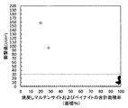
- FIG. 2 is a graph showing the relationship between the total area ratio of tempered martensite and bainite and the Charpy impact value.
- the inventors of the present invention have made extensive studies in order to realize a fracture separation type connecting rod with improved strength while preventing cracking during quenching and improving fracture separation. As a result, it is possible to increase the strength if the metal structure is mainly composed of a tempered martensite and bainite composite structure, and even in such a composite structure, if the component composition is appropriately controlled, quench cracking during quenching can be achieved.
- the inventors have found that the risk of occurrence can be reduced and that the fracture separability can be improved by appropriately controlling the DI value, which is a hardenability index, and the embodiments of the present invention have been completed.
- the above connecting rod steel has a total area ratio of tempered martensite and bainite of 80 area% or more with respect to the entire metal structure. Since the strength of the steel for connecting rods can be increased by setting the total area ratio to 80 area% or more, the strength of the connecting rod can be increased.
- the total area ratio of tempered martensite and bainite was determined by calculating the total area ratio of ferrite, pearlite, and retained austenite with respect to the metal structure as described in the Examples section below. What is necessary is just to obtain
- the total area ratio of the tempered martensite and bainite is preferably 85 area% or more, more preferably 90 area% or more, based on the entire metal structure.
- the upper limit of the total area ratio is not particularly limited, but is most preferably 100 area%.
- the total area ratio of the tempered martensite and bainite can be controlled by adjusting the DI value described later to a range of 55 to 200 mm.
- % means mass%
- the C amount is an element necessary for ensuring strength and reducing toughness. Moreover, when the amount of C decreases, the martensitic transformation start temperature increases, and it becomes difficult for the steel material to be baked and the strength is decreased. From such a viewpoint, the C amount needs to be 0.01% or more.
- the amount of C is preferably 0.05% or more, more preferably 0.10% or more.
- the C amount needs to be 0.5% or less.
- the amount of C is preferably 0.4% or less, more preferably 0.35% or less.
- the Si is an element that acts as a deoxidizer, and is an element that acts to improve yield strength and fatigue strength by increasing hardenability and improving strength.
- the Si amount is preferably 0.01% or more, more preferably 0.04% or more.
- the Si amount needs to be 0.7% or less.
- the amount of Si is preferably 0.5% or less, more preferably 0.4% or less.
- Mn is an element necessary for enhancing hardenability and ensuring strength. When the amount of Mn is too small, the strength decreases and temper embrittlement is suppressed. Therefore, in the embodiment of the present invention, the amount of Mn is 0.01% or more.
- the amount of Mn is preferably 0.3% or more, more preferably 1.0% or more.
- Mn is an element that stabilizes austenite, when the amount of Mn becomes excessive, retained austenite is generated after tempering. As a result, the strength is lowered, the toughness is increased, and the break separation property cannot be improved. From such a viewpoint, the amount of Mn needs to be 3% or less.
- the amount of Mn is preferably 2.5% or less, more preferably 2.3% or less.
- P is an element necessary for suppressing toughness and suppressing deformation when the connecting rod obtained by cutting is broken and separated. From this viewpoint, the P amount is set to 0.001% or more.
- the amount of P is preferably 0.01% or more, more preferably 0.03% or more. However, when P is contained excessively, the occurrence of casting defects is induced during continuous casting. From this point of view, the P amount needs to be 0.2% or less.
- the amount of P is preferably 0.15% or less, more preferably 0.08% or less.
- the amount of S is an element that contributes to improving machinability by being hardly dissolved in steel and concentrating stress on the chips.
- the amount of S is preferably 0.01% or more.
- the amount of S is more preferably 0.02% or more, still more preferably 0.03% or more.
- the S amount needs to be 0.2% or less.
- the amount of S is preferably 0.15% or less, more preferably 0.12% or less.
- the Cr amount is an element necessary for improving hardenability and ensuring strength.
- the Cr amount is 0.01% or more.
- the amount of Cr is preferably 0.05% or more, more preferably 0.5% or more.
- the Cr amount needs to be 3% or less.
- the amount of Cr is preferably 2.5% or less, more preferably 2.3% or less.
- Al is an element that acts as a deoxidizer.
- the Al content is preferably 0.0001% or more.
- the amount of Al is more preferably 0.001% or more, and still more preferably 0.002% or more.
- the Al amount needs to be 0.1% or less.
- the amount of Al is preferably 0.08% or less, more preferably 0.05% or less.
- N is an unavoidable impurity, and if the amount of N is excessive, the hot workability deteriorates, making it difficult to manufacture. From this point of view, the N amount needs to be 0.03% or less.
- the N amount is preferably 0.025% or less, more preferably 0.020% or less. N is preferably as small as possible, but it is difficult to make it 0% by ordinary steelmaking technology, and usually about 0.005% is contained.
- the balance of the steel is substantially iron. However, it is naturally allowed that inevitable impurities brought from raw materials, materials, manufacturing facilities, etc. are contained in the steel.
- the fracture separating type connecting rod steel according to an embodiment of the present invention, as other elements, (A) at least one selected from Cu: more than 0% and 0.2% or less, Ni: more than 0% and 0.2% or less, and Mo: more than 0% and 0.2% or less, (B) selected from Pb: more than 0% and 0.2% or less, Bi: more than 0% and 0.2% or less, Te: more than 0% and 0.2% or less, and Ca: more than 0% and 0.005% or less At least one (C) Mg: more than 0% and 0.01% or less, Zr: more than 0% and 0.01% or less, REM: more than 0% and 0.01% or less, Sn: more than 0% and 0.20% or less, and B: At least one selected from the following formula (2): Etc. may be contained.
- [] indicates the content of each element in mass%. 0 ⁇ [B] / [N] ⁇ 14 / 10.8 ⁇ 1 (2)
- Cu, Ni, and Mo are all elements that improve the hardenability and can increase the strength.
- Cu, Ni, and Mo can be used alone or in combination of two or more.
- the amount of Cu is preferably more than 0.05%, more preferably 0.06% or more, and still more preferably 0.10% or more.
- the amount of Ni is preferably more than 0.05%, more preferably 0.06% or more, and further preferably 0.10% or more.
- the amount of Mo is preferably more than 0.05%, more preferably 0.06% or more, still more preferably 0.10% or more.
- the amount of Cu is preferably 0.2% or less.
- the amount of Cu is more preferably 0.15% or less, and still more preferably 0.10% or less.
- the Ni amount is preferably 0.2% or less.
- the amount of Ni is more preferably 0.15% or less, and still more preferably 0.10% or less.
- the Mo amount is preferably 0.2% or less.
- the amount of Mo is more preferably 0.15% or less, still more preferably 0.10% or less.
- Pb, Bi, Te, and Ca are elements that enhance machinability.
- Pb, Bi, Te, and Ca can be used alone or in combination of two or more.
- Pb, Bi, and Te are hardly dissolved in steel and have an effect of improving machinability due to effects such as melt embrittlement.
- the amount of Pb is more preferably 0.03% or more, still more preferably 0.1% or more.
- Bi is preferably contained in an amount of 0.01% or more.
- the Bi amount is more preferably 0.03% or more, and still more preferably 0.1% or more.
- Te is preferably contained in an amount of 0.01% or more.
- the amount of Te is more preferably 0.03% or more, and still more preferably 0.1% or more.
- the Pb amount is preferably 0.2% or less.
- the amount of Pb is more preferably 0.15% or less, still more preferably 0.12% or less.
- the amount of Bi is preferably 0.2% or less.
- the amount of Bi is more preferably 0.15% or less, still more preferably 0.12% or less.
- the amount of Te is preferably 0.2% or less.
- the amount of Te is more preferably 0.15% or less, and still more preferably 0.12% or less.
- Ca is an element that enhances machinability due to effects such as the formation of a bellag (tool protective film). It also has the effect of spheroidizing sulfide inclusions to promote embrittlement.
- Ca is preferably contained in an amount of 0.0001% or more.
- the amount of Ca is more preferably 0.0005% or more, and further preferably 0.0010% or more. It is better to contain Ca as much as possible, but even if it is contained excessively, the effect is saturated and the cost is increased. Therefore, in the embodiment of the present invention, the Ca content is preferably 0.005% or less.
- the amount of Ca is more preferably 0.004% or less, and still more preferably 0.003% or less.
- Mg, Zr, REM and Sn are free-cutting elements. Further, B is a free-cutting element because BN is formed when N is sufficient, and BN brings about a lubricating action with the tool. Mg, Zr, REM, Sn and B can be used alone or in combination of two or more.
- Mg, Zr, and REM are hardly dissolved in steel, but are dissolved in sulfide inclusions and the like, and also have an effect of promoting the embrittlement by spheroidizing the sulfide inclusions.
- Mg may be positively contained in an amount of 0.0001% or more, and more preferably 0.001% or more.
- Zr may be positively contained in an amount of 0.0001% or more, and more preferably 0.001% or more.
- REM may be positively contained in an amount of 0.0001% or more, more preferably 0.001% or more.
- Mg, Zr or REM is contained excessively, the manufacturing cost is increased.
- the Mg content is preferably 0.01% or less, more preferably 0.008% or less, and still more preferably 0.005% or less.
- the amount of Zr is preferably 0.01% or less, more preferably 0.008% or less, and still more preferably 0.005% or less.
- the amount of REM is preferably 0.01% or less, more preferably 0.008% or less, and still more preferably 0.005% or less.
- Sn is hardly dissolved in steel and has the effect of improving machinability due to effects such as melt embrittlement.
- Sn may be positively contained in an amount of 0.01% or more, and more preferably 0.03% or more.
- the Sn content is preferably 0.20% or less, more preferably 0.15% or less, and still more preferably 0.12% or less.
- B forms BN when N is sufficient, and BN brings about a lubricating action with the tool, and therefore becomes a free-cutting element.
- B may be positively contained in an amount of 0.0001% or more, and more preferably 0.0005% or more.
- the B amount preferably satisfies the following formula (2).
- [] indicates the content of each element in mass%. 0 ⁇ [B] / [N] ⁇ 14 / 10.8 ⁇ 1 (2)
- the upper limit of the formula (2) is more preferably 0.95 or less, and still more preferably 0.90 or less.
- the DI value calculated by the following formula (1) satisfies 55 to 200 mm after satisfying the above component composition.
- the DI value is called a hardenability index, and represents the depth at which quenching occurs when quenched.
- the greater the DI value the easier it is for martensite to be generated. Since martensite is a main cause of embrittlement, the greater the DI value, the better the brittleness and the stable strength.
- the above DI value is the characteristics and structure of a low YR type 780 MPa class round steel pipe for building structures with excellent HAZ toughness published in “R & D, Kobe Steel Engineering, Vol. 61, No. 2, August 2011”. It is a value calculated based on the following formula (1) designed by modifying the following formula (a) described in “Control Technology (pages 16 to 19)”. That is, in the following formula (a), it is not taken into account that when the amount of S increases, the amount of dissolved Mn decreases due to the generation of MnS.
- a decrease in the amount of solid solution Mn due to MnS generation is added to the following formula (a) from the atomic weight ratio between the atomic weight 55 of Mn and the atomic weight 32 of S, and the following formula (1) Designed.
- [] means content in the mass% of each element.
- V and B since V and B are not contained, the terms V and B defined by the following formula (a) are deleted. In order to convert the unit from inch to mm, 25.4 was multiplied in the following formula (1).
- the DI value is 55 mm or more.
- the DI value is preferably 60 mm or more, more preferably 70 mm or more.
- the DI value is 200 mm or less.
- the DI value is preferably 190 mm or less, more preferably 180 mm or less.
- the embodiment of the present invention also includes a fracture separation type connecting rod obtained using the above steel for connecting rods.
- This connecting rod satisfies all the requirements for the component composition, DI value, and metal structure defined in the steel for connecting rods.
- the connecting rod according to the embodiment of the present invention has high strength because the metal structure is tempered martensite and bainite, and the strength is about 800 to 1400 MPa.
- the above steel for connecting rods is a tempered material that is hot-forged from a steel material satisfying the above-mentioned composition prepared according to a conventional method, and then quenched at a quenching temperature of 700 ° C. or higher and then tempered at a tempering temperature of 200 to 400 ° C. It can be manufactured by processing.
- the metal structure of the steel can be completely austenitic.
- the quenching temperature is preferably 800 ° C. or higher, more preferably 850 ° C. or higher.
- the upper limit of the quenching temperature is not particularly limited, but is preferably 1300 ° C. or lower so as not to melt.
- the quenching temperature is more preferably 1200 ° C. or less, further preferably 1100 ° C. or less, and particularly preferably 1000 ° C. or less.
- the quenching may be water quenching or oil quenching.
- the average cooling rate during quenching is preferably 20 ° C./second or more, more preferably 100 ° C./second or more.
- the upper limit of the average cooling rate at the time of quenching is not particularly limited, but if the cooling rate is too high, the risk of occurrence of quenching cracks increases, so the upper limit is preferably 500 ° C./second or less.
- the average cooling rate at the time of quenching is more preferably 400 ° C./second or less, and still more preferably 300 ° C./second or less.
- the tempering temperature is 200 ° C. or higher, preferably 250 ° C. or higher.
- the tempering temperature is 400 ° C. or lower, preferably 375 ° C. or lower.
- the steel for connecting rods obtained by quenching and tempering has a thickness of about 10 to 50 mm on one side of a portion excluding a through hole at a large end portion where fracture separation is performed.
- the obtained steel bar was cut perpendicularly to the longitudinal direction to produce a steel bar having a length of 90 mm.
- the obtained 90 mm long steel bar was held at 900 ° C. for 30 minutes, and then water quenched at a quenching temperature of 900 ° C.
- the average cooling rate during water quenching was about 100 ° C./second.
- Burn cracking means cracks as well as cracks.
- the number of samples was set to 7 each, and the case where no burning cracks occurred was judged as “no burning cracks” and the case where even one burning crack occurred was judged as “burning cracks”.
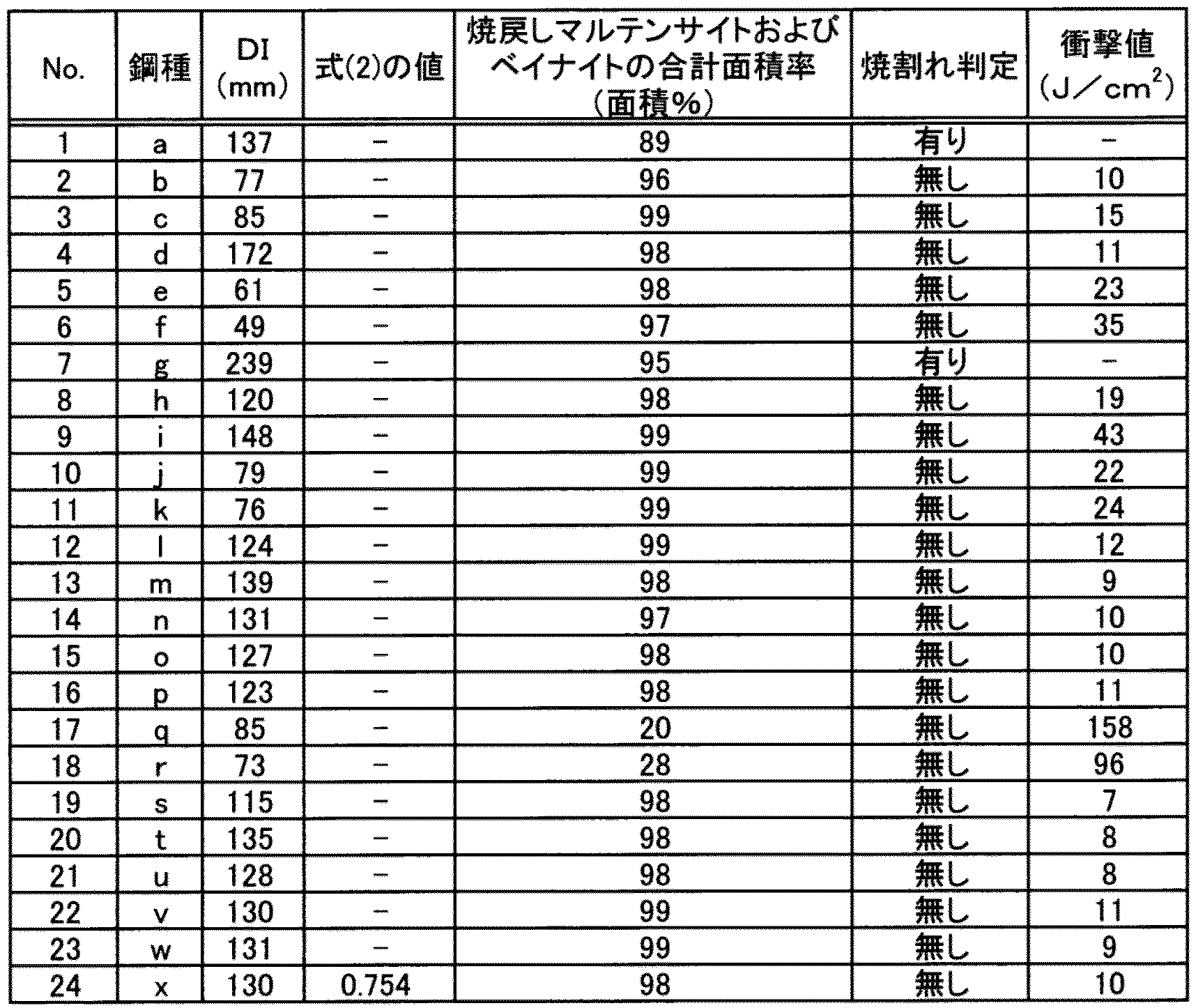
- Table 2 shows the determination results. The case where there was no burning crack was regarded as acceptable, and the case where there was burning crack was regarded as unacceptable.
- the metal structure of the steel bar obtained by tempering was observed according to the following procedure.
- the steel bar was embedded in the resin so that the center position in the longitudinal direction of the steel bar obtained by tempering and in the diametrical direction could be observed, the surface was mirror-polished, and it was corroded with nital to test the metal structure.
- Pieces were produced.
- the obtained test piece was photographed with an optical microscope at a magnification of 400 with a photographic size of one field of view of 9 cm ⁇ 7 cm, the photographed image was subjected to image analysis, and the total area ratio of ferrite and pearlite with respect to the entire metal structure was measured. .
- the surface of the test piece that was corroded with nital and observed the metal structure was polished by 100 ⁇ m by electrolytic polishing, and the ratio of retained austenite to the entire metal structure (100% by volume) using an X-ray diffractometer ( Volume fraction) was measured.
- the total area ratio (area%) of ferrite, pearlite, and residual austenite with respect to the entire metal structure was determined by regarding the volume ratio of retained austenite as the area ratio.
- the total area ratio (area%) of tempered martensite and bainite is obtained by subtracting the total area ratio (area%) of ferrite, pearlite, and retained austenite from the total (100 area%). %).
- the case where the Charpy impact value was 30 J / cm 2 or less was excellent in break separation and was evaluated as acceptable.
- the Charpy impact value is 30 J / cm 2 or less, deformation at break separation can be sufficiently suppressed.
- No. Nos. 2 to 5, 8, 10 to 16, and 19 to 24 are examples that satisfy the requirements defined in the embodiment of the present invention, and the total area ratio of tempered martensite and bainite is 80% or more. Regardless, since the component composition and DI value are appropriately controlled, no quench cracking occurs during quenching, and the fracture separation is excellent.
- No. 1, 6, 7, 9, 17, and 18 are examples that do not satisfy any of the requirements defined in the embodiment of the present invention.
- No. No. 1 is an example in which the amount of C is excessive, and quenching cracks occurred during quenching.
- No. No. 6 is an example in which the DI value falls below the range specified in the embodiment of the present invention, and the Charpy impact value becomes large, and deformation occurs at the time of break separation, so the break separation property cannot be improved.
- No. No. 7 is an example in which the DI value exceeds the range specified in the embodiment of the present invention, and a quench crack occurred during quenching.
- No. Nos. 17 and 18 are examples in which the total area ratio of tempered martensite and bainite was less than 80 area% with respect to the entire metal structure because no quenching was performed. As a result, the Charpy impact value is increased, and the fracture separability cannot be improved.
- FIG. 1 shows No. 1 that satisfies the requirements defined in the embodiment of the present invention.
- the component composition satisfies the requirements specified in the embodiment of the present invention.
- the DI value does not satisfy the range defined in the embodiment of the present invention. 6 is plotted with ⁇ .
- No. 7 also corresponds to an example in which the DI value does not satisfy the range specified in the embodiment of the present invention even though the component composition satisfies the requirements specified in the embodiment of the present invention. Since the Charpy impact value was not measured, it was not plotted.
- the Charpy impact value can be suppressed to 30 J / cm 2 or less, so that the fracture separation can be improved.
- FIG. 2 shows No. 1 that satisfies the requirements defined in the embodiment of the present invention.
- the component composition and the DI value are the requirements specified in the embodiment of the present invention.
- the total area ratio of tempered martensite and bainite does not satisfy the range defined in the embodiment of the present invention. 17 and 18 were plotted with ⁇ .
- the Charpy impact value can be suppressed to 30 J / cm 2 or less by controlling the total area ratio of tempered martensite and bainite to 80 area% or more, and it can be seen that the fracture separability can be improved. .
- the present application includes a Japanese patent application filed on December 3, 2015, Japanese Patent Application No. 2015-236842, and a Japanese patent application filed on August 25, 2016, Japanese Patent Application No. 2016- Accompanying priority claim with 164611 as the basic application.
- Japanese Patent Application No. 2015-236842 and Japanese Patent Application No. 2016-164611 are incorporated herein by reference.
Landscapes
- Engineering & Computer Science (AREA)
- Chemical & Material Sciences (AREA)
- Mechanical Engineering (AREA)
- Materials Engineering (AREA)
- Metallurgy (AREA)
- Organic Chemistry (AREA)
- General Engineering & Computer Science (AREA)
- Physics & Mathematics (AREA)
- Thermal Sciences (AREA)
- Crystallography & Structural Chemistry (AREA)
- Heat Treatment Of Steel (AREA)
Abstract
金属組織を焼戻しマルテンサイトとすることによって強度を高めたうえで、焼入れ時に焼割れを発生させることなく、破断分離性を改善した破断分離型コネクティングロッド、および該破断分離型コネクティングロッドを製造する素材となる破断分離型コネクティングロッド用鋼、並びにこれらの製造方法を提供する。 下記式(1)で算出されるDI値が55~200mmであり、金属組織全体に対して、焼戻しマルテンサイトおよびベイナイトの合計面積率が80面積%以上である破断分離型コネクティングロッド用鋼。下記式(1)において、[ ]は、各元素の質量%での含有量を示す。 DI(mm)=1.16×([C]/10)1/2×(0.7×[Si]+1)×〔5.1×{[Mn]-1.2-(55/32×[S])}+5〕×(0.35×[Cu]+1)×(0.36×[Ni]+1)×(2.16×[Cr]+1)×(3×[Mo]+1)×25.4 ・・・(1)
Description
本開示は、破断分離型コネクティングロッド用鋼、該鋼を用いた破断分離型コネクティングロッド、およびこれらの製造方法に関する。なお、本発明の破断分離型コネクティングロッド用鋼は、調質処理を施すことを前提とした調質鋼である。
自動車エンジン等の内燃機関には、ピストンとクランクシャフトとの間を連結し、ピストンの往復運動をクランクシャフトに伝えて回転運動に変換する部品としてコネクティングロッドが用いられている。このコネクティングロッドは、コネクティングロッド本体とコネクティングロッドキャップから構成され、これらがクランクシャフトを挟むようにしてクランクシャフトに取り付けられる。
従来、コネクティングロッド本体とコネクティングロッドキャップは別々に製造されていた。しかし、別々に製造されたコネクティングロッドでは、コネクティングロッド本体とコネクティングロッドキャップの嵌合性を高めるために、嵌合面を切削などによって精密加工する必要があり、また嵌合面がずれないようにノックピン加工を施すのが一般的であった。こうした製造方法では、材料の歩留まりが低下したり、製造が煩雑となるといった問題があった。
そこで、近年では、コネクティングロッド本体とコネクティングロッドキャップを熱間鍛造によって一体的に成型し、クランクシャフトを挿入するための貫通孔またはボルトを挿入するための穴等を切削加工した後、貫通孔部分が2つの略半円になるように、冷間加工によってコネクティングロッド本体とコネクティングロッドキャップに破断分離する方法が採用されている。このようにして得られたコネクティングロッド本体とコネクティングロッドキャップは、クランクシャフトを挟んでコネクティングロッド本体とコネクティングロッドキャップの破面同士を嵌合し、ボルトで締結して組み立てられ、コネクティングロッドとされる。こうした製造方法では、嵌合面となる破面を切削などによって精密加工することも、ノックピン加工を施す必要もなくなる。このようにして製造されるコネクティングロッドを、以下では破断分離型コネクティングロッドと呼ぶ。
自動車用内燃機関部品等に用いられる熱間鍛造部品に関し、レーザー等によるノッチを設けた際に良好な破断分割性を確保できる熱間鍛造部品を提供する技術が特許文献1に提案されている。特許文献1に記載の熱間鍛造部品は、Vを0.03~0.20%未満、Tiを0.015~0.1%含有し、フェライト組織とパーライト組織の合計面積率が全組織に対して90%以上であるとともに、(フェライト粒度番号F)-(旧オーステナイト粒度番号A)≧3を満たすところに特徴がある。しかし上記特許文献1では、高価なVおよびTiなどの元素を含有させているためコストが高くなる。
ところで、自動車の燃費向上のため、上記コネクティングロッドには高強度化が求められている。しかし、上記特許文献1に開示されている熱間鍛造部品は、フェライト組織とパーライト組織の合計面積率が全組織に対して90%以上であるため、高強度化するには限界があった。
コネクティングロッドを高強度化する方法として、金属組織を焼戻しマルテンサイトとすることが考えられる。しかし、金属組織を焼戻しマルテンサイトにすると、靭性が高くなり、破断分離性が悪化することが分かった。そこで、破断分離性を改善するには、Cの含有量を多くすることが考えられる。しかし、C量を過剰に高めると、焼入れ時に焼割れ発生のリスクが高くなる。また、強度が過剰に高くなるため、部品形状への加工性が劣化するおそれがある。
本発明の実施形態は上記の様な事情に着目してなされたものであって、その目的は、金属組織を焼戻しマルテンサイトとすることによって強度を高めたうえで、焼入れ時に焼割れを発生させることなく、破断分離性を改善した破断分離型コネクティングロッド、および該破断分離型コネクティングロッドを製造する素材となる破断分離型コネクティングロッド用鋼、並びにこれらの製造方法を提供することにある。
上記課題を解決することのできた本発明の実施形態に係る破断分離型コネクティングロッド用鋼は、質量%で、C:0.01~0.5%、Si:0%超0.7%以下、Mn:0.01~3%、P:0.001~0.2%、S:0%超0.2%以下、Cr:0.01~3%、Al:0%超0.1%以下、およびN:0%超0.03%以下を含有し、残部が鉄および不可避的不純物である。そして、下記式(1)で算出されるDI値が55~200mmであり、金属組織全体に対して、焼戻しマルテンサイトおよびベイナイトの合計面積率が80面積%以上である点に要旨を有する。下記式(1)において、[ ]は、各元素の質量%での含有量を示す。
DI(mm)=1.16×([C]/10)1/2×(0.7×[Si]+1)×〔5.1×{[Mn]-1.2-(55/32×[S])}+5〕×(0.35×[Cu]+1)×(0.36×[Ni]+1)×(2.16×[Cr]+1)×(3×[Mo]+1)×25.4 ・・・(1)
DI(mm)=1.16×([C]/10)1/2×(0.7×[Si]+1)×〔5.1×{[Mn]-1.2-(55/32×[S])}+5〕×(0.35×[Cu]+1)×(0.36×[Ni]+1)×(2.16×[Cr]+1)×(3×[Mo]+1)×25.4 ・・・(1)
更に、他の元素として、質量%で、
(a)Cu:0%超0.2%以下、Ni:0%超0.2%以下、およびMo:0%超0.2%以下から選択される少なくとも1種、
(b)Pb:0%超0.2%以下、Bi:0%超0.2%以下、Te:0%超0.2%以下、およびCa:0%超0.005%以下から選択される少なくとも1種、
(c)Mg:0%超0.01%以下、Zr:0%超0.01%以下、REM:0%超0.01%以下、Sn:0%超0.20%以下、およびB:下記式(2)を満足する量から選択される少なくとも1種、
等を含有してもよい。下記式(2)において、[ ]は、各元素の質量%での含有量を示す。
0<[B]/[N]×14/10.8≦1 ・・・(2)
(a)Cu:0%超0.2%以下、Ni:0%超0.2%以下、およびMo:0%超0.2%以下から選択される少なくとも1種、
(b)Pb:0%超0.2%以下、Bi:0%超0.2%以下、Te:0%超0.2%以下、およびCa:0%超0.005%以下から選択される少なくとも1種、
(c)Mg:0%超0.01%以下、Zr:0%超0.01%以下、REM:0%超0.01%以下、Sn:0%超0.20%以下、およびB:下記式(2)を満足する量から選択される少なくとも1種、
等を含有してもよい。下記式(2)において、[ ]は、各元素の質量%での含有量を示す。
0<[B]/[N]×14/10.8≦1 ・・・(2)
本発明の実施形態には、上記破断分離型コネクティングロッド用鋼を用いた破断分離型コネクティングロッドも包含される。
上記破断分離型コネクティングロッド用鋼は、上記成分組成を満足する鋼材を、熱間鍛造した後、焼入れ温度700℃以上で焼入れを行い、次いで焼戻し温度200~400℃で焼戻しを行うことによって製造できる。
上記破断分離型コネクティングロッドは、上記破断分離型コネクティングロッド用鋼を、切削加工した後、破断分離することによって製造できる。
なお、焼戻しマルテンサイトは、後述するようにベイナイトと区別がつきにくいため、本発明の実施形態に係る破断分離型コネクティングロッド用鋼では、金属組織全体に対する焼戻しマルテンサイトおよびベイナイトの合計面積率を規定している。破断分離型コネクティングロッドについても同じである。
本発明の実施形態によれば、金属組織を焼戻しマルテンサイトおよびベイナイトとしているため高強度化できる。また、成分組成を適切に制御しているため、焼入れ時に焼割れが発生するのを防止でき、更に焼入れ性指数であるDI値を適切に制御しているため、靭性を低くできる。その結果、破断分離性を改善した高強度の破断分離型コネクティングロッド用鋼を提供できる。この鋼を用いた破断分離型コネクティングロッドは、高強度で、しかも破断分離性に優れている。
本発明者らは、強度を高めたうえで、焼入れ時に焼割れが発生するのを防止しつつ、破断分離性を改善した破断分離型コネクティングロッドを実現するために、鋭意検討を重ねた。その結果、金属組織は、焼戻しマルテンサイトとベイナイトの複合組織を主体とすれば、強度を高めることができること、こうした複合組織であっても、成分組成を適切に制御すれば、焼入れ時の焼割れ発生リスクを低減できること、焼入れ性指数であるDI値を適切に制御すれば破断分離性を改善できることを見出し、本発明の実施形態を完成した。
まず、本発明の実施形態に係る破断分離型コネクティングロッドの素材となる破断分離型コネクティングロッド用鋼について説明する。
上記コネクティングロッド用鋼は、金属組織全体に対して、焼戻しマルテンサイトおよびベイナイトの合計面積率が80面積%以上である。上記合計面積率を80面積%以上とすることによって、コネクティングロッド用鋼の強度を高めることができるため、コネクティングロッドを高強度化できる。
なお、焼戻しマルテンサイトおよびベイナイトの合計面積率は、後記する実施例の項で説明するように、金属組織に対するフェライト、パーライト、および残留オーステナイトの合計面積率を求め、これを金属組織全体(100%)から引いた残部として求めればよい。また、焼戻しマルテンサイトとベイナイトは区別しにくいため、本発明の実施形態では、これらを区別せずに合計量として算出すればよい。
上記焼戻しマルテンサイトおよびベイナイトの合計面積率は、金属組織全体に対して、好ましくは85面積%以上、より好ましくは90面積%以上である。上記合計面積率の上限は特に限定されないが、最も好ましくは100面積%である。
上記焼戻しマルテンサイトおよびベイナイトの合計面積率は、後述するDI値を55~200mmの範囲に調整することによって制御できる。
次に、上記コネクティングロッド用鋼の成分組成について説明する。以下、%は、質量%を意味する。
Cは、強度を確保すると共に、靭性を小さくするために必要な元素である。また、C量が少なくなると、マルテンサイト変態開始温度が上昇し、鋼材に焼きが入りにくくなり、強度が低下する。こうした観点から、C量は0.01%以上とする必要がある。C量は、好ましくは0.05%以上、更に好ましくは0.10%以上である。しかし、C量が過剰になると、強度が高くなり過ぎて被削性が劣化する。また、焼入れ時における焼割れの主要因にもなる。こうした観点からC量は0.5%以下とする必要がある。C量は、好ましくは0.4%以下、より好ましくは0.35%以下である。
Siは、脱酸剤として作用する元素であり、また、焼入れ性を高め、強度を向上させることにより耐力および疲労強度を向上させるのに作用する元素である。こうした効果を有効に発揮させるには、Si量は、好ましくは0.01%以上、より好ましくは0.04%以上である。しかし、Si量が過剰になると、強度が高くなり過ぎて被削性が劣化する。また、過剰なSiは、焼戻し脆化を抑制し、靭性を高め、破断分離性を劣化する原因となる。従って、本発明の実施形態では、Si量は0.7%以下とする必要がある。Si量は、好ましくは0.5%以下、より好ましくは0.4%以下である。
Mnは、焼入れ性を高め、強度を確保するために必要な元素である。Mn量が少なすぎると、強度が低下すると共に、焼戻し脆化が抑制される。従って、本発明の実施形態では、Mn量は、0.01%以上とする。Mn量は、好ましくは0.3%以上、より好ましくは1.0%以上である。しかし、Mnは、オーステナイトを安定化させる元素であるため、Mn量が過剰になると、調質後に残留オーステナイトが生成する。その結果、強度が却って低下し、靭性が高くなり、破断分離性を改善できない。こうした観点からMn量は、3%以下とする必要がある。Mn量は、好ましくは2.5%以下、より好ましくは2.3%以下である。
Pは、靭性を抑え、切削加工して得られたコネクティングロッドを破断分離するときの変形を抑制するために必要な元素である。こうした観点からP量は、0.001%以上とする。P量は、好ましくは0.01%以上、より好ましくは0.03%以上である。しかし、Pを過剰に含有すると、連続鋳造時に鋳造欠陥の発生が誘発される。こうした観点からP量は0.2%以下とする必要がある。P量は、好ましくは0.15%以下、より好ましくは0.08%以下である。
Sは、鋼中にほとんど固溶せず、切り屑へ応力集中させることによって被削性を高めるのに寄与する元素である。こうした効果を有効に発揮させるには、S量は、0.01%以上とすることが好ましい。S量は、より好ましくは0.02%以上、更に好ましくは0.03%以上である。しかし、Sを過剰に含有すると、連鋳割れ、熱間鍛造割れ、疲労強度低下の原因となる。従って、本発明の実施形態では、S量は、0.2%以下とする必要がある。S量は、好ましくは0.15%以下、より好ましくは0.12%以下である。
Crは、焼入れ性を高め、強度を確保するために必要な元素である。Cr量が少なすぎると、焼戻し脆化が抑制される。従って、本発明の実施形態では、Cr量は、0.01%以上とする。Cr量は、好ましくは0.05%以上、より好ましくは0.5%以上である。しかし、Crを過剰に含有すると、焼戻し脆化が抑制されるため、靭性が高くなり過ぎ、破断分離性を改善できない。こうした観点からCr量は、3%以下とする必要がある。Cr量は、好ましくは2.5%以下、より好ましくは2.3%以下である。
Alは、脱酸剤として作用する元素である。こうした効果を有効に発揮させるには、Al量は、0.0001%以上が好ましい。Al量は、より好ましくは0.001%以上、更に好ましくは0.002%以上である。しかし、Al量が過剰になると、熱間加工性が悪くなるため、製造することが困難になる。こうした観点からAl量は、0.1%以下とする必要がある。Al量は、好ましくは0.08%以下、より好ましくは0.05%以下である。
Nは、不可避的不純物であり、N量が過剰になると、熱間加工性が悪くなるため、製造することが困難になる。こうした観点からN量は、0.03%以下とする必要がある。N量は、好ましくは0.025%以下、より好ましくは0.020%以下である。Nは、できるだけ少ない方が好ましいが、通常の製鋼技術では0%にすることは困難であり、通常、0.005%程度は含有する。
上記鋼の残部は、実質的に鉄である。但し、原材料、資材または製造設備等から持ち込まれる不可避的不純物が鋼中に含まれることは当然に許容される。
本発明の実施形態に係る破断分離型コネクティングロッド用鋼は、上記元素に加え、更に、他の元素として、
(a)Cu:0%超0.2%以下、Ni:0%超0.2%以下、およびMo:0%超0.2%以下から選択される少なくとも1種、
(b)Pb:0%超0.2%以下、Bi:0%超0.2%以下、Te:0%超0.2%以下、およびCa:0%超0.005%以下から選択される少なくとも1種、
(c)Mg:0%超0.01%以下、Zr:0%超0.01%以下、REM:0%超0.01%以下、Sn:0%超0.20%以下、およびB:下記式(2)で表される量以下から選択される少なくとも1種、
等を含有してもよい。下記式(2)において、[ ]は、各元素の質量%での含有量を示す。
0<[B]/[N]×14/10.8≦1 ・・・(2)
(a)Cu:0%超0.2%以下、Ni:0%超0.2%以下、およびMo:0%超0.2%以下から選択される少なくとも1種、
(b)Pb:0%超0.2%以下、Bi:0%超0.2%以下、Te:0%超0.2%以下、およびCa:0%超0.005%以下から選択される少なくとも1種、
(c)Mg:0%超0.01%以下、Zr:0%超0.01%以下、REM:0%超0.01%以下、Sn:0%超0.20%以下、およびB:下記式(2)で表される量以下から選択される少なくとも1種、
等を含有してもよい。下記式(2)において、[ ]は、各元素の質量%での含有量を示す。
0<[B]/[N]×14/10.8≦1 ・・・(2)
(a)Cu、Ni、およびMoは、いずれも焼入れ性を向上させる元素であり、強度を高めることができる。Cu、Ni、およびMoは、単独で、あるいは2種以上を併用できる。こうした効果を有効に発揮させるには、Cu量は、好ましくは0.05%超、より好ましくは0.06%以上、更に好ましくは0.10%以上である。Ni量は、好ましくは0.05%超、より好ましくは0.06%以上、更に好ましくは0.10%以上である。Mo量は、好ましくは0.05%超、より好ましくは0.06%以上、更に好ましくは0.10%以上である。
しかし、Cu量が過剰になると、熱間加工性が悪くなり、製造することが困難になるため、Cu量は、0.2%以下が好ましい。Cu量は、より好ましくは0.15%以下、更に好ましくは0.10%以下である。Ni量が過剰になると、靭性が高くなりすぎるため、破断分離性が劣化する。従って、本発明の実施形態では、Ni量は0.2%以下が好ましい。Ni量は、より好ましくは0.15%以下、更に好ましくは0.10%以下である。Mo量が過剰になると、焼戻し脆化が抑制され、靭性が高くなりすぎるため、破断分離性が劣化する。従って、本発明の実施形態では、Mo量は、0.2%以下が好ましい。Mo量は、より好ましくは0.15%以下、更に好ましくは0.10%以下である。
(b)Pb、Bi、Te、およびCaは、被削性を高める元素である。Pb、Bi、Te、およびCaは、単独で、あるいは2種以上を併用できる。
これらの元素のうち、特にPb、Bi、およびTeは、鋼中にほとんど固溶せず、溶融脆化などの効果によって被削性を高める作用を有する。こうした効果を有効に発揮させるには、Pbは、0.01%以上含有することが好ましい。Pb量は、より好ましくは0.03%以上、更に好ましくは0.1%以上である。Biは、0.01%以上含有することが好ましい。Bi量は、より好ましくは0.03%以上、更に好ましくは0.1%以上である。Teは、0.01%以上含有することが好ましい。Te量は、より好ましくは0.03%以上、更に好ましくは0.1%以上である。しかし、Pb、Bi、およびTeを過剰に含有すると、連鋳割れ、熱間鍛造割れ、または疲労強度低下の原因となる。こうした観点からPb量は、0.2%以下が好ましい。Pb量は、より好ましくは0.15%以下、更に好ましくは0.12%以下である。Bi量は、0.2%以下が好ましい。Bi量は、より好ましくは0.15%以下、更に好ましくは0.12%以下である。Te量は、0.2%以下が好ましい。Te量は、より好ましくは0.15%以下、更に好ましくは0.12%以下である。
Caは、ベラーグ(工具保護膜)生成などの効果によって被削性を高める元素である。また、硫化物系介在物を球状化して脆化を促進する効果も有する。こうした効果を発揮させるには、Caは、0.0001%以上含有することが好ましい。Ca量は、より好ましくは0.0005%以上、更に好ましくは0.0010%以上である。Caはできるだけ含有する方が良いが、過剰に含有しても効果が飽和し、コスト上昇を招く。従って、本発明の実施形態では、Ca量は、0.005%以下が好ましい。Ca量は、より好ましくは0.004%以下、更に好ましくは0.003%以下である。
(c)Mg、Zr、REMおよびSnは快削性元素である。また、Bは、Nが十分にあるとBNを形成し、BNが工具との潤滑作用をもたらすため、快削性元素となる。Mg、Zr、REM、SnおよびBは、単独で、あるいは2種以上を併用できる。
これらの元素のうち、Mg、ZrおよびREMは、鋼中にほとんど固溶せず、硫化物系介在物などに溶け込み、硫化物系介在物を球状化して脆化を促進する効果も持つ。良好な被削性を得るために、Mgは0.0001%以上積極的に含有させてもよく、より好ましくは0.001%以上である。Zrは0.0001%以上積極的に含有させてもよく、より好ましくは0.001%以上である。REMは0.0001%以上積極的に含有させてもよく、より好ましくは0.001%以上である。しかし、Mg、ZrまたはREMを過剰に含有すると、製造コストの上昇を招く。従って、Mg量は0.01%以下であることが好ましく、より好ましくは0.008%以下、さらに好ましくは0.005%以下である。Zr量は0.01%以下であることが好ましく、より好ましくは0.008%以下、さらに好ましくは0.005%以下である。REM量は0.01%以下であることが好ましく、より好ましくは0.008%以下、さらに好ましくは0.005%以下である。
Snは、鋼中にほとんど固溶せず、溶融脆化などの効果により被削性を高める効果を持つ。良好な被削性を得るために、Snは0.01%以上積極的に含有させてもよく、より好ましくは0.03%以上である。しかし、Snを過剰に含有すると、連鋳割れ、熱間鍛造割れ、または疲労強度低下の原因となる。従って、Sn量は0.20%以下であることが好ましく、より好ましくは0.15%以下、さらに好ましくは0.12%以下である。
Bは、上述のように、Nが十分にある場合にBNを形成し、BNが工具との潤滑作用をもたらすため、快削性元素となる。良好な被削性を得るために、Bは0.0001%以上積極的に含有させてもよく、より好ましくは0.0005%以上である。しかし、Bを過剰に含有すると、Bが固溶してしまい、靱性向上の原因となる。従って、B量は、下記式(2)を満足することが好ましい。下記式(2)において、[ ]は、各元素の質量%での含有量を示す。
0<[B]/[N]×14/10.8≦1 ・・・(2)
上記式(2)の上限は、より好ましくは0.95以下、さらに好ましくは0.90以下である。
0<[B]/[N]×14/10.8≦1 ・・・(2)
上記式(2)の上限は、より好ましくは0.95以下、さらに好ましくは0.90以下である。
本発明の実施形態に係るコネクティングロッド用鋼は、上記成分組成を満足したうえで、下記式(1)で算出されるDI値が55~200mmを満足することが重要である。上記DI値は、焼入れ性指数と呼ばれており、焼入れしたときに焼きが入る深さを表している。DI値が大きいほど、マルテンサイトが生成しやすくなる。マルテンサイトは、脆化が生じる主要因となるため、DI値が大きいほど良好な脆性と安定した強度を両立できる。
上記DI値は、「R&D、神戸製鋼技法、Vol.61、No.2、2011年8月」に掲載されている「HAZ靭性に優れた建築構造用低YR型780MPa級円形鋼管の特性と組織制御技術(16~19頁)」に記載の下記式(a)を変形して設計した下記式(1)に基づいて算出した値である。即ち、下記式(a)では、S量が多くなった場合に、MnSの生成によって固溶Mn量が減少することが考慮されていない。そこで、本発明の実施形態では、下記式(a)に対して、Mnの原子量55とSの原子量32の原子量比からMnS生成による固溶Mn量の減少分を加味し、下記式(1)を設計した。なお、下記式(a)、(1)において、[ ]は、各元素の質量%での含有量を意味する。また、本発明の実施形態では、VとBは含有しないため、下記式(a)で規定するVとBの項は削除した。また、単位をinchからmmに換算するために、下記式(1)では25.4を掛けた。
DI(inch)=1.16×([C]/10)1/2×(0.7×[Si]+1)×〔5.1×{[Mn]-1.2}+5〕×(0.35×[Cu]+1)×(0.36×[Ni]+1)×(2.16×[Cr]+1)×(3×[Mo]+1)×(1.75×[V]+1)×(200×[B]+1) ・・・(a)
DI(mm)=1.16×([C]/10)1/2×(0.7×[Si]+1)×〔5.1×{[Mn]-1.2-(55/32×[S])}+5〕×(0.35×[Cu]+1)×(0.36×[Ni]+1)×(2.16×[Cr]+1)×(3×[Mo]+1)×25.4 ・・・(1)
DI(inch)=1.16×([C]/10)1/2×(0.7×[Si]+1)×〔5.1×{[Mn]-1.2}+5〕×(0.35×[Cu]+1)×(0.36×[Ni]+1)×(2.16×[Cr]+1)×(3×[Mo]+1)×(1.75×[V]+1)×(200×[B]+1) ・・・(a)
DI(mm)=1.16×([C]/10)1/2×(0.7×[Si]+1)×〔5.1×{[Mn]-1.2-(55/32×[S])}+5〕×(0.35×[Cu]+1)×(0.36×[Ni]+1)×(2.16×[Cr]+1)×(3×[Mo]+1)×25.4 ・・・(1)
上記DI値が55mmを下回ると、靭性が高くなり、破断分離時に変形が発生するため、破断分離性を改善できない。従って、本発明の実施形態では、上記DI値は、55mm以上とする。上記DI値は、好ましくは60mm以上、より好ましくは70mm以上である。しかし、上記DI値が過剰に大きくなると、焼入れ時に焼割れ発生のリスクが増大する。また、強度が高くなり過ぎて部品形状への加工性が悪化する。従って、本発明の実施形態では、上記DI値は、200mm以下とする。上記DI値は、好ましくは190mm以下、より好ましくは180mm以下である。
以上、本発明の実施形態に係るコネクティングロッド用鋼について説明した。
本発明の実施形態には、上記コネクティングロッド用鋼を用いて得られた破断分離型コネクティングロッドも含まれる。このコネクティングロッドは、上記コネクティングロッド用鋼で規定した成分組成、DI値、および金属組織の要件を全て満足している。なお、本発明の実施形態に係るコネクティングロッドは、金属組織を焼戻しマルテンサイトおよびベイナイトとしているため、高強度化できており、その強度は、おおよそ800~1400MPa程度である。
次に、本発明の実施形態に係るコネクティングロッド用鋼の製造方法について説明する。上記コネクティングロッド用鋼は、常法に従って調製した上記成分組成を満足する鋼材を、熱間鍛造した後、焼入れ温度700℃以上で焼入れを行い、次いで焼戻し温度200~400℃で焼戻しを行う調質処理を施すことによって製造できる。
上記焼入れ温度を700℃以上とすることによって、鋼材の金属組織を完全にオーステナイト化できる。上記焼入れ温度は、好ましくは800℃以上、より好ましくは850℃以上である。上記焼入れ温度の上限は特に限定されないが、溶融させないために、1300℃以下とすることが好ましい。上記焼入れ温度は、より好ましくは1200℃以下、更に好ましくは1100℃以下、特に好ましくは1000℃以下である。
上記焼入れは、水焼入れでもよいし、油焼入れでもよい。焼入れ時の平均冷却速度は、好ましくは20℃/秒以上、より好ましくは100℃/秒以上である。上記焼入れ時の平均冷却速度の上限は特に限定されないが、冷却速度が大きすぎると、焼割れ発生のリスクが高まるため、上限は、好ましくは500℃/秒以下である。上記焼入れ時の平均冷却速度は、より好ましくは400℃/秒以下、更に好ましくは300℃/秒以下である。
上記焼入れした後は、脆化を促進するために、焼戻しを行う。上記焼戻し温度が200℃を下回ると、可動転位が多量に残留するため、耐力比が著しく下がり、脆化が充分に得られないことがある。従って、本発明の実施形態では、焼戻し温度は200℃以上とし、好ましくは250℃以上である。脆化を最も促進するには、300℃付近の温度域で焼き戻すことが望ましい。しかし、焼戻し温度が高すぎると、靭性が向上し、脆化が充分に得られないことがある。従って、本発明の実施形態では、焼戻し温度は400℃以下とし、好ましくは375℃以下である。
上記焼入れ焼戻しして得られたコネクティングロッド用鋼は、破断分離を行う大端部の貫通孔を除いた部分の片側の太さが、おおよそ10~50mm程度である。得られた棒鋼を、常法に従って切削加工し、破断分離することによって、破断分離性に優れたコネクティングロッドが得られる。
以下、実施例を挙げて本発明の実施形態をより具体的に説明するが、本発明の実施形態は下記実施例によって制限を受けるものではなく、前記および後記の趣旨に適合し得る範囲で変更を加えて実施することも勿論可能であり、それらはいずれも本開示の技術的範囲に包含される。
下記表1に示す成分組成(残部は、鉄および不可避的不純物)の鋼を、常法に従って溶製し、鋳造し、分塊した後、加熱温度を1200℃として鍛伸し、直径18mmの棒鋼を製造した。下記表1に示した成分組成および上記式(1)に基づいて算出したDI値を、下記表2に示す。なお、下記表1に示したCu、Ni、およびMo量のうち、本発明の実施形態では、0.05%以下を不可避的不純物として扱い、0.05%超を積極添加元素として扱う。
得られた棒鋼を長手方向に対して垂直に切断し、長さ90mmの棒鋼を製造した。
得られた長さ90mmの棒鋼を、900℃で30分間保持した後、焼入れ温度900℃で水焼入れを行った。水焼入れ時の平均冷却速度は約100℃/秒であった。
水焼入れ後、焼割れ発生の有無を目視で観察した。焼割れは、割れの他、ヒビも含む意味である。サンプル数は、7本ずつとし、焼割れが全く発生しなかった場合を「焼割れ無し」、1本でも焼割れが発生した場合を「焼割れ有り」と判定した。下記表2に、判定結果を示す。焼割れ無しの場合を合格、焼割れ有りの場合を不合格とした。
次に、水焼入れして得られた長さ90mmの棒鋼のうち、下記表2に示したNo.1~16、19については、焼戻し温度300℃で3時間保持して焼戻しを行った。
一方、下記表2に示したNo.17、18は、切断して得られた長さ90mmの棒鋼を、900℃で30分間保持した後、焼入れせず、放冷して常温まで冷却した。その後、焼戻し温度300℃で3時間保持して焼戻しを行った。
次に、焼戻しして得られた棒鋼について、下記手順で金属組織の観察を行った。即ち、焼戻しして得られた棒鋼の長手方向の中央部で、且つ直径方向の中心位置を観察できるように棒鋼を樹脂に埋め込み、表面を鏡面研磨し、ナイタールで腐食させて金属組織観察用試験片を製造した。得られた試験片について、光学顕微鏡を用い、1視野の写真サイズを9cm×7cmとして400倍で撮影し、撮影した写真を画像解析し、金属組織全体に対するフェライトおよびパーライトの合計面積率を測定した。
次に、ナイタールで腐食させて金属組織を観察した上記試験片の表面を、電解研磨にて100μm研磨し、X線回折装置を用いて、金属組織全体(100体積%)に対する残留オーステナイトの割合(体積率)を測定した。残留オーステナイトの体積率を面積率と見なして金属組織全体に対するフェライト、パーライト、および残留オーステナイトの合計面積率(面積%)を求めた。
金属組織全体を100面積%としたとき、全体(100面積%)からフェライト、パーライト、および残留オーステナイトの合計面積率(面積%)を引いた残りを、焼戻しマルテンサイトおよびベイナイトの合計面積率(面積%)とした。
次に、焼戻しして得られた棒鋼のうち、焼入れ時に焼割れが発生したNo.1、7以外について、下記手順でシャルピー衝撃値を測定した。即ち、焼戻しして得られた棒鋼を切削し、JIS Z2242(2005年)で規定される10mm角のシャルピー衝撃試験片に加工した。ノッチは長手方向に対して垂直方向に深さ2mmのUノッチとした。シャルピー衝撃試験は、JIS Z2242(2005年)に従い、常温で行った。サンプル数は3個とし、平均値を求めた。結果を下記表2に併せて示す。
本発明の実施形態では、シャルピー衝撃値が30J/cm2以下の場合を破断分離性に優れ、合格と評価した。シャルピー衝撃値が30J/cm2以下であると、破断分離時の変形を充分に抑制できる。
下記表1、表2から次のように考察できる。
No.2~5、8、10~16、19~24は、いずれも本発明の実施形態で規定する要件を満足する例であり、焼戻しマルテンサイトおよびベイナイトの合計面積率が80%以上であるにもかかわらず、成分組成およびDI値を適切に制御しているため、焼入れ時に焼割れが発生せず、破断分離性に優れている。
一方、No.1、6、7、9、17、18は、いずれも本発明の実施形態で規定するいずれかの要件を満足しない例である。
これらのうち、No.1は、C量が過剰な例であり、焼入れ時に焼割れが発生した。
No.6は、DI値が本発明の実施形態で規定する範囲を下回る例であり、シャルピー衝撃値が大きくなり、破断分離時に変形が発生するため、破断分離性を改善できていない。
No.7は、DI値が本発明の実施形態で規定する範囲を超える例であり、焼入れ時に焼割れが発生した。
No.9は、Moを過剰に含有するため、シャルピー衝撃値が大きくなり、破断分離時に変形が発生し、破断分離性を改善できていない。
No.17、18は、焼入れを行っていないため、金属組織全体に対して、焼戻しマルテンサイトおよびベイナイトの合計面積率が80面積%を下回った例である。その結果、シャルピー衝撃値が大きくなり、破断分離性を改善できていない。
次に、DI値とシャルピー衝撃値の関係を図1に示す。図1には、本発明の実施形態で規定する要件を満足するNo.2~5、8、10~16、19~24を◆、本発明の実施形態で規定するいずれかの要件を満足しない例のうち、成分組成は本発明の実施形態で規定する要件を満足するが、DI値が本発明の実施形態で規定する範囲を満足しないNo.6を◇でプロットした。なお、No.7も成分組成は本発明の実施形態で規定する要件を満足するにもかかわらず、DI値が本発明の実施形態で規定する範囲を満足しない例に該当するが、焼入れ時に焼割れが発生し、シャルピー衝撃値を測定しなかったため、プロットしなかった。
図1から明らかなように、DI値を55~200mmに制御することによって、シャルピー衝撃値を30J/cm2以下に抑制できるため、破断分離性を改善できることが分かる。
次に、焼戻しマルテンサイトおよびベイナイトの合計面積率と、シャルピー衝撃値の関係を図2に示す。図2には、本発明の実施形態で規定する要件を満足するNo.2~5、8、10~16、19~24を◆、本発明の実施形態で規定するいずれかの要件を満足しない例のうち、成分組成およびDI値は本発明の実施形態で規定する要件を満足するが、焼戻しマルテンサイトおよびベイナイトの合計面積率が本発明の実施形態で規定する範囲を満足しないNo.17、18を◇でプロットした。
図2から明らかなように、焼戻しマルテンサイトおよびベイナイトの合計面積率を80面積%以上に制御することによって、シャルピー衝撃値を30J/cm2以下に抑制できるため、破断分離性を改善できることが分かる。

本出願は、出願日が2015年12月3日である日本国特許出願、特願第2015-236842号、及び出願日が2016年8月25日である日本国特許出願、特願第2016-164611号を基礎出願とする優先権主張を伴う。特願第2015-236842号および特願第2016-164611号は参照することにより本明細書に取り込まれる。
Claims (11)
- 質量%で、
C :0.01~0.5%、
Si:0%超0.7%以下、
Mn:0.01~3%、
P :0.001~0.2%、
S :0%超0.2%以下、
Cr:0.01~3%、
Al:0%超0.1%以下、および
N :0%超0.03%以下を含有し、
残部が鉄および不可避的不純物であり、
下記式(1)で算出されるDI値が55~200mmであり、
金属組織全体に対して、焼戻しマルテンサイトおよびベイナイトの合計面積率が80面積%以上であることを特徴とする破断分離型コネクティングロッド用鋼。
DI(mm)=1.16×([C]/10)1/2×(0.7×[Si]+1)×〔5.1×{[Mn]-1.2-(55/32×[S])}+5〕×(0.35×[Cu]+1)×(0.36×[Ni]+1)×(2.16×[Cr]+1)×(3×[Mo]+1)×25.4 ・・・(1)
上記式(1)において、[ ]は、各元素の質量%での含有量を示す。 - 更に、他の元素として、質量%で、
Cu:0%超0.2%以下、
Ni:0%超0.2%以下、および
Mo:0%超0.2%以下から選択される少なくとも1種を含有する請求項1に記載の鋼。 - 更に、他の元素として、質量%で、
Pb:0%超0.2%以下、
Bi:0%超0.2%以下、
Te:0%超0.2%以下、および
Ca:0%超0.005%以下から選択される少なくとも1種を含有する請求項1に記載の鋼。 - 更に、他の元素として、質量%で、
Pb:0%超0.2%以下、
Bi:0%超0.2%以下、
Te:0%超0.2%以下、および
Ca:0%超0.005%以下から選択される少なくとも1種を含有する請求項2に記載の鋼。 - 更に、他の元素として、質量%で、
Mg:0%超0.01%以下、
Zr:0%超0.01%以下、
REM:0%超0.01%以下、
Sn:0%超0.20%以下、および
B:下記式(2)を満足する量から選択される少なくとも1種を含有する請求項1に記載の鋼。
0<[B]/[N]×14/10.8≦1 ・・・(2)
上記式(2)において、[ ]は、各元素の質量%での含有量を示す。 - 更に、他の元素として、質量%で、
Mg:0%超0.01%以下、
Zr:0%超0.01%以下、
REM:0%超0.01%以下、
Sn:0%超0.20%以下、および
B:下記式(2)を満足する量から選択される少なくとも1種を含有する請求項2に記載の鋼。
0<[B]/[N]×14/10.8≦1 ・・・(2)
上記式(2)において、[ ]は、各元素の質量%での含有量を示す。 - 更に、他の元素として、質量%で、
Mg:0%超0.01%以下、
Zr:0%超0.01%以下、
REM:0%超0.01%以下、
Sn:0%超0.20%以下、および
B:下記式(2)を満足する量から選択される少なくとも1種を含有する請求項3に記載の鋼。
0<[B]/[N]×14/10.8≦1 ・・・(2)
上記式(2)において、[ ]は、各元素の質量%での含有量を示す。 - 更に、他の元素として、質量%で、
Mg:0%超0.01%以下、
Zr:0%超0.01%以下、
REM:0%超0.01%以下、
Sn:0%超0.20%以下、および
B:下記式(2)を満足する量から選択される少なくとも1種を含有する請求項4に記載の鋼。
0<[B]/[N]×14/10.8≦1 ・・・(2)
上記式(2)において、[ ]は、各元素の質量%での含有量を示す。 - 請求項1~8のいずれかに記載の鋼を用いた破断分離型コネクティングロッド。
- 請求項1~8のいずれかに記載の成分組成を満足する鋼材を、熱間鍛造した後、焼入れ温度700℃以上で焼入れを行い、次いで焼戻し温度200~400℃で焼戻しを行うことを特徴とする破断分離型コネクティングロッド用鋼の製造方法。
- 請求項10に記載の製造方法で得られた破断分離型コネクティングロッド用鋼を、切削加工した後、破断分離することを特徴とする破断分離型コネクティングロッドの製造方法。
Applications Claiming Priority (4)
| Application Number | Priority Date | Filing Date | Title |
|---|---|---|---|
| JP2015-236842 | 2015-12-03 | ||
| JP2015236842 | 2015-12-03 | ||
| JP2016-164611 | 2016-08-25 | ||
| JP2016164611A JP2017106099A (ja) | 2015-12-03 | 2016-08-25 | 破断分離型コネクティングロッド用鋼、破断分離型コネクティングロッド、およびこれらの製造方法 |
Publications (1)
| Publication Number | Publication Date |
|---|---|
| WO2017094446A1 true WO2017094446A1 (ja) | 2017-06-08 |
Family
ID=58797107
Family Applications (1)
| Application Number | Title | Priority Date | Filing Date |
|---|---|---|---|
| PCT/JP2016/082914 Ceased WO2017094446A1 (ja) | 2015-12-03 | 2016-11-07 | 破断分離型コネクティングロッド用鋼、破断分離型コネクティングロッド、およびこれらの製造方法 |
Country Status (1)
| Country | Link |
|---|---|
| WO (1) | WO2017094446A1 (ja) |
Cited By (2)
| Publication number | Priority date | Publication date | Assignee | Title |
|---|---|---|---|---|
| CN112522568A (zh) * | 2019-09-19 | 2021-03-19 | 宝山钢铁股份有限公司 | 一种耐火耐候钢板/带及其制造方法 |
| US20230031552A1 (en) * | 2019-12-20 | 2023-02-02 | Posco | Wire rod for high-strength steel fiber, high-strength steel fiber, and method for manufacturing same |
Citations (5)
| Publication number | Priority date | Publication date | Assignee | Title |
|---|---|---|---|---|
| JPH09310122A (ja) * | 1996-05-21 | 1997-12-02 | Kobe Steel Ltd | 高強度コネクティングロッドの製法 |
| JPH1112678A (ja) * | 1997-06-24 | 1999-01-19 | Sumitomo Metal Ind Ltd | マルテンサイト・ベイナイト型熱間鍛造部品及びその製造方法 |
| JP2002194492A (ja) * | 2000-12-22 | 2002-07-10 | Sanyo Special Steel Co Ltd | 高硬度部品 |
| JP2005120397A (ja) * | 2003-10-14 | 2005-05-12 | Kobe Steel Ltd | 絞り特性に優れた高強度鍛造部品 |
| JP2009108357A (ja) * | 2007-10-29 | 2009-05-21 | Nippon Steel Corp | マルテンサイト型熱間鍛造用非調質鋼及び熱間鍛造非調質鋼部品 |
-
2016
- 2016-11-07 WO PCT/JP2016/082914 patent/WO2017094446A1/ja not_active Ceased
Patent Citations (5)
| Publication number | Priority date | Publication date | Assignee | Title |
|---|---|---|---|---|
| JPH09310122A (ja) * | 1996-05-21 | 1997-12-02 | Kobe Steel Ltd | 高強度コネクティングロッドの製法 |
| JPH1112678A (ja) * | 1997-06-24 | 1999-01-19 | Sumitomo Metal Ind Ltd | マルテンサイト・ベイナイト型熱間鍛造部品及びその製造方法 |
| JP2002194492A (ja) * | 2000-12-22 | 2002-07-10 | Sanyo Special Steel Co Ltd | 高硬度部品 |
| JP2005120397A (ja) * | 2003-10-14 | 2005-05-12 | Kobe Steel Ltd | 絞り特性に優れた高強度鍛造部品 |
| JP2009108357A (ja) * | 2007-10-29 | 2009-05-21 | Nippon Steel Corp | マルテンサイト型熱間鍛造用非調質鋼及び熱間鍛造非調質鋼部品 |
Cited By (3)
| Publication number | Priority date | Publication date | Assignee | Title |
|---|---|---|---|---|
| CN112522568A (zh) * | 2019-09-19 | 2021-03-19 | 宝山钢铁股份有限公司 | 一种耐火耐候钢板/带及其制造方法 |
| US20230031552A1 (en) * | 2019-12-20 | 2023-02-02 | Posco | Wire rod for high-strength steel fiber, high-strength steel fiber, and method for manufacturing same |
| US12410489B2 (en) * | 2019-12-20 | 2025-09-09 | Posco | Wire rod for high-strength steel fiber, high-strength steel fiber, and method for manufacturing same |
Similar Documents
| Publication | Publication Date | Title |
|---|---|---|
| JP5563926B2 (ja) | 摩擦圧接に適した機械構造用鋼材および衝撃特性、曲げ疲労特性に優れた摩擦圧接部品 | |
| WO2011004913A1 (ja) | 高強度ばね用鋼線 | |
| JP6427272B2 (ja) | ボルト | |
| JP6614393B2 (ja) | 非調質棒鋼 | |
| WO2013132829A1 (ja) | ばね鋼 | |
| KR101547015B1 (ko) | 대형 고강도 단강품 | |
| JP2014218683A (ja) | 軟窒化クランクシャフト及びその製造方法 | |
| JP5319374B2 (ja) | 一体型クランク軸およびその製造方法 | |
| KR20180102166A (ko) | 단조용 강 및 대형 단강품 | |
| JP3893889B2 (ja) | 破断による分離が容易な熱間鍛造用非調質鋼 | |
| JP2017106099A (ja) | 破断分離型コネクティングロッド用鋼、破断分離型コネクティングロッド、およびこれらの製造方法 | |
| JP5432590B2 (ja) | 破断分割性に優れた熱間鍛造部品とその製造方法、および自動車用内燃機関部品 | |
| WO2017094446A1 (ja) | 破断分離型コネクティングロッド用鋼、破断分離型コネクティングロッド、およびこれらの製造方法 | |
| JP4938474B2 (ja) | 耐衝撃疲労特性、面疲労強度に優れた歯車用鋼及びそれを用いた歯車 | |
| JP2017179475A (ja) | 破断分離型コネクティングロッド用成型部品、及びコネクティングロッド、並びに該コネクティングロッドの製造方法 | |
| JP2022130746A (ja) | 非調質鍛造部品および非調質鍛造用鋼 | |
| KR101800563B1 (ko) | 고강도 강, 및 상기 고강도 강을 이용한 크랭크축 | |
| JP4396561B2 (ja) | 高周波焼入れ用鋼 | |
| JP5916553B2 (ja) | コネクティングロッド用鋼及びコネクティングロッド | |
| JP5880795B2 (ja) | 時効硬化性鋼 | |
| KR20180102167A (ko) | 고강도 단강 및 대형 단조 부품 | |
| KR102101233B1 (ko) | 강 | |
| JP2008144211A (ja) | V含有非調質鋼 | |
| JP4910654B2 (ja) | 疲労強度の高いクランクシャフト | |
| KR101185302B1 (ko) | 단조분할 커넥팅로드용 고강도 비조질강 및 그 제조 방법 |
Legal Events
| Date | Code | Title | Description |
|---|---|---|---|
| 121 | Ep: the epo has been informed by wipo that ep was designated in this application |
Ref document number: 16870386 Country of ref document: EP Kind code of ref document: A1 |
|
| NENP | Non-entry into the national phase |
Ref country code: DE |
|
| 122 | Ep: pct application non-entry in european phase |
Ref document number: 16870386 Country of ref document: EP Kind code of ref document: A1 |