WO2017094412A1 - 往復動工具 - Google Patents
往復動工具 Download PDFInfo
- Publication number
- WO2017094412A1 WO2017094412A1 PCT/JP2016/082061 JP2016082061W WO2017094412A1 WO 2017094412 A1 WO2017094412 A1 WO 2017094412A1 JP 2016082061 W JP2016082061 W JP 2016082061W WO 2017094412 A1 WO2017094412 A1 WO 2017094412A1
- Authority
- WO
- WIPO (PCT)
- Prior art keywords
- base
- housing
- base plate
- reciprocating tool
- reciprocating
- Prior art date
- Legal status (The legal status is an assumption and is not a legal conclusion. Google has not performed a legal analysis and makes no representation as to the accuracy of the status listed.)
- Ceased
Links
Images

Classifications
-
- B—PERFORMING OPERATIONS; TRANSPORTING
- B23—MACHINE TOOLS; METAL-WORKING NOT OTHERWISE PROVIDED FOR
- B23D—PLANING; SLOTTING; SHEARING; BROACHING; SAWING; FILING; SCRAPING; LIKE OPERATIONS FOR WORKING METAL BY REMOVING MATERIAL, NOT OTHERWISE PROVIDED FOR
- B23D49/00—Machines or devices for sawing with straight reciprocating saw blades, e.g. hacksaws
- B23D49/10—Hand-held or hand-operated sawing devices with straight saw blades
- B23D49/16—Hand-held or hand-operated sawing devices with straight saw blades actuated by electric or magnetic power or prime movers
-
- B—PERFORMING OPERATIONS; TRANSPORTING
- B23—MACHINE TOOLS; METAL-WORKING NOT OTHERWISE PROVIDED FOR
- B23D—PLANING; SLOTTING; SHEARING; BROACHING; SAWING; FILING; SCRAPING; LIKE OPERATIONS FOR WORKING METAL BY REMOVING MATERIAL, NOT OTHERWISE PROVIDED FOR
- B23D51/00—Sawing machines or sawing devices working with straight blades, characterised only by constructional features of particular parts; Carrying or attaching means for tools, covered by this subclass, which are connected to a carrier at both ends
- B23D51/02—Sawing machines or sawing devices working with straight blades, characterised only by constructional features of particular parts; Carrying or attaching means for tools, covered by this subclass, which are connected to a carrier at both ends of beds; of guiding arrangements for work-tables or saw carriers; of frames
Definitions
- the present invention relates to a reciprocating tool that cuts a workpiece by a reciprocating blade, and more particularly to a reciprocating tool that reduces vibrations transmitted to a base portion due to reciprocating movement of the blade.
- a jigsaw for a reciprocating tool that performs work by converting the rotational motion of a motor as a drive source into the reciprocating motion of a tip tool.
- the jigsaw is covered by a reciprocating blade while moving the main body part forward in the cutting direction with the horizontal base part attached to the lower part of the main body part of the housing being in contact with the material to be cut.
- the cutting material is cut (see, for example, Patent Document 1).
- the housing 2 has a substantially D-shaped appearance that is formed by molding resin or the like and formed into a left-right two-divided type and is tilted sideways in a side view.
- the housing 2 has a motor housing portion 2b for housing a motor 6 disposed so that the rotary shaft 7 is in the horizontal direction, and a motion conversion mechanism housing portion 2c having a predetermined space long in the vertical direction on the front side of the motor housing portion 2b.
- a handle portion 2a extending so as to connect the upper side of the motion conversion mechanism housing portion 2c and the rear side of the motor housing portion 2b to the upper side.
- the handle portion 2a is a portion that is held by an operator with one hand.
- a trigger switch 19 for switching the motor 6 on and off is accommodated inside the handle portion 2a, and a trigger lever operated by the operator is provided below the handle portion 2a. 19a is provided.
- a speed adjustment dial 25 for adjusting the rotational speed of the motor 6 is provided on the front side of the handle portion 2a.
- a motor 6 is provided in the motor housing 2b, and a power cable 26 for supplying commercial power is provided near the rear end of the housing 2.
- the cooling fan 5 is fixed to the rotating shaft 7 of the motor 6, and a pinion gear 7a is provided at the front end portion thereof.
- the pinion gear 7a meshes with a gear portion 9 formed integrally with the eccentric cam.
- the gear portion 9 rotates about the rotation shaft 8 and constitutes a power conversion mechanism that converts the power of the motor 6, and the rear side of the gear portion 9 is a flat gear that rotates concentrically with the rotation shaft 7.
- An eccentric cam 9b is formed on the front side.
- the outer peripheral shape of the eccentric cam 9 b is circular, and the center of the eccentric cam 9 b is formed to be eccentric from the rotation center of the rotary shaft 7.
- a balance weight 16 is disposed around the eccentric cam 9b.
- the balance weight 16 is integrally formed of metal, and has an elongated hole 16a that accommodates the eccentric cam 9b.
- the long axis of the long hole 16a is formed so as to extend in the horizontal direction, and when the eccentric cam 9b rotates inside the long hole 16a, the contact portion thereof changes and the balance weight 16 moves in the vertical direction.
- the movement direction of the balance weight 16 is restricted in the vertical direction by a linear slit (not shown) extending in the vertical direction.
- a holder 11 is fixed to the front side of the eccentric cam 9b using screws.
- the holder 11 is integrally formed of steel and is connected to a connecting rail 13 extending in the horizontal direction via a needle bearing 12.
- the connecting rail 13 is formed by extruding steel and is held on the upper end side of the plunger 14.
- the balance weight 16 is lowered when the plunger is raised, and the balance weight 16 is lowered when the plunger is lowered.
- the counterweight caused by the movement of the plunger 14 and a blade (not shown) attached below the plunger 14 is canceled by the balance weight 16.
- a blade holding part 15 for attaching a blade is provided at the lower end of the plunger 14.
- a tip cover 35 for preventing scattering of cutting dust or the like is provided on the front side of the blade holding portion 15.
- the blade holding part 15 is provided at the tip part (lower end part) of the plunger 14 and holds the blade in a detachable manner.
- the plunger 14 has a substantially cylindrical shape, and is supported by the housing 2 so as to be reciprocable and rotatable in the vertical direction.
- the plunger guide 18 is supported so as to be slidable in the vertical direction at a substantially central portion in the vertical direction.
- the plunger guide 18 is urged in the radial direction by the spring 17 at the outer peripheral portion thereof, thereby allowing the orbital operation of the plunger 14 in the front-rear direction.
- An orbital cam 21a is connected to the eccentric cam 9a, and when the gear portion 9 rotates, the orbital cam 21a moves up and down, and an action piece 21b integrally provided at the lower end thereof is one end side of the inverted L-shaped roller holder 22 Is pressed or released, and the roller holder 22 is swung around the swing shaft 23 to move the roller 24 provided on the other end side of the roller holder 22 in the front-rear direction.
- the roller 24 is located at the front end portion of the roller holder 22 and supports the roller 24 rotatably.
- the roller 24 is formed with a circumferentially continuous groove for guiding a blade (not shown) at the left and right center of the outer peripheral surface, and the orbital mechanism portion 20 presses the back portion opposite to the blade edge side of the blade. Orbital operation is possible.
- the base 130 is fixed via a bolt 48 with a part of the gear cover 3 interposed on the bottom surface side of the motor accommodating portion 2b so that the longitudinal direction coincides with the cutting direction.
- the base 130 has a bottom surface having a relatively large area so that the jigsaw 101 can be pressed against the material to be cut so as not to rattle stably.
- the base 130 is mainly composed of a base base 131 and a base plate 141. On the upper surface of the base base 131, an arcuate protruding portion 131a for fixing to the base mounting portion 2d of the housing with a bolt 48 is formed.
- a base plate 141 facing the material to be cut is provided below the base base 131 (on the opposite side of the housing).
- the jigsaw 101 has the dividing surface of the housing 2 perpendicular to the base 130 and cuts the material to be cut vertically, but the housing 2 is inclined with respect to the base 130 and covered at an arbitrary angle. It is also possible to cut the cutting material.
- the base 130 is provided with openings 131a and 141a for inserting blades (not shown) on the front side of the main surface portion.
- the openings 131a and 141a are formed in a substantially U-shape when viewed from the bottom so as to open to the front side.
- the openings 131a and 141a are parallel to both the left and right sides in the cutting direction by a blade extending downward in the openings 131a and 141a.
- An elongated guide surface extending in the direction is formed.
- a screw hole 131b for fixing to the housing 2 via a bolt 48 see FIG.
- the outer edge shape of the base plate 141 is a similar shape corresponding to the outer edge shape of the base base 131 and has an outer edge slightly smaller than the base base 131 in a bottom view.
- the base plate 141 is screwed to the base base 131 with four screws 134a, 134b, 135a, 135b.
- Low friction agents 136a and 136b for reducing the frictional force with the material to be cut are applied or pasted to the bottom surface of the base plate 141 on the rear side of the screws 134a and 134b.
- a base portion is provided on the lower side of the housing in order to stably position the jigsaw on the upper surface of the material to be cut.
- the bottom surface of the base portion is flat, and the cutting operation is performed while pressing the flat portion against the material to be cut.
- a jigsaw has a balancer using a balance weight for canceling vibrations generated when the blade reciprocates.
- the vibration cannot be completely canceled with the balancer alone, the vibration accompanying the reciprocating motion is transmitted from the base portion to the workpiece. Since transmission of this vibration becomes a hindrance requirement for improving cutting accuracy, it is preferable to suppress vibration transmitted from the base plate to the material to be cut as much as possible.
- the present invention has been made in view of the above background, and an object thereof is to provide a reciprocating tool capable of effectively reducing vibrations caused by reciprocating motion from being transmitted from a base portion to a workpiece.
- a motor housed in a housing, a plunger that can be fitted with a blade at the tip and driven and reciprocated by the motor, and is mounted on the housing and moves on the workpiece together with the housing
- a reciprocating tool having a base portion, and the base portion is configured by a base base held by the housing and a base plate attached to the non-housing side of the base base, the base base and the base plate And a base base that supports a base plate via an elastic body, and the contact part and the elastic support part are separated from each other in the direction in which the motor and the plunger are arranged.
- the base plate is swingable with the contact part as a fulcrum, and is close to and away from the base base at the elastic support part. It was to swing to so that.
- a base mounting part for mounting the base base is provided on the lower side of the housing, the base base is mounted on the base mounting part near the center of the base base in the cutting direction, and the contact part and the elastic support part are Arranged in a region that does not overlap with the position of the base mounting portion in bottom view.
- the base plate has a main surface located on the rear side of the opening through which the blade passes, and two guide surfaces extending in parallel to the front side on both sides of the opening, and the abutting portion is the main surface or An elastic support portion is disposed on one side of the guide surface and the other side.
- the base plate is a flexible metal plate, and a movement stroke equal to or greater than the plate thickness of the metal plate is secured in the movement direction of the plunger using a spring in the elastic support portion.
- the abutment portion is fixed by screws so that the base plate contacts the lower surface of the base base, and the base base and the base plate are kept in a non-contact state with a gap in a region facing the base mounting portion.
- the housing further includes a motor housing portion that houses the motor so that the rotation shaft is in the horizontal direction, a motion conversion mechanism housing portion that extends in the vertical direction on the front side of the motor housing portion and houses the plunger, and a motion conversion mechanism housing.
- the upper part of the contact part and the rear side of the motor housing part are connected to each other on the upper side. Positioned on one side in the front-rear direction with respect to the center of gravity position of the tool, so that the movement conversion mechanism that is the source of vibration and the holding position by the elastic support portion are positioned on the other side in the front-rear direction with respect to the center position of the reciprocating tool did.
- the motion conversion mechanism includes a plunger, a balancer for canceling vibrations by reciprocating in the opposite phase to the plunger, and reciprocating the plunger and balancer by the rotational force of the motor.
- a power conversion mechanism when the housing is lifted with the base base positioned horizontally, the amount of protrusion of the base plate from the base base in the downward direction is small at the contact portion between the base base and the base plate in the cutting direction, and is elastic. The size was increased on the support side.
- the base plate was formed of a metal plate having spring properties.
- vibration generated on the main body side of the housing can be greatly suppressed from being transmitted to the material to be cut due to the base plate swinging with respect to the base main body. Further, since the elastic body is interposed between the base plate and the swinging side, the vibration transmitted to the material to be cut is greatly suppressed, and the cutting accuracy can be improved. Furthermore, since the vibration of the housing is suppressed for the operator, the fatigue of the cutting operation can be greatly reduced.
- FIG. 80 It is a bottom view of the base 80 of the jigsaw which concerns on the 3rd Example of this invention. It is a longitudinal cross-sectional view which shows the whole structure of the conventional jigsaw 101. FIG. It is a bottom view of the base 130 of the conventional jigsaw 101. FIG.
- FIG. 1 is a right side view of a jigsaw 1 as an example of a reciprocating tool according to an embodiment of the present invention.
- the housing 2 and the main body housed therein are the same as the internal structure of the jigsaw 101 described in FIG.
- the configuration of the base portion (base 30) attached to the base mounting portion 2d of the housing 2 is improved.
- the base 30 is mainly configured by a base base 31 attached to the base mounting portion 2d and a base plate 41 fixed by the base base 31.
- the base plate 41 is disposed on the lower side (on the opposite side of the housing) of the base base 31 and forms a grounding surface that comes into contact with the material to be cut.
- the base plate 41 moves while sliding on the upper surface of the material to be cut during the cutting operation.
- the shape of the base plate 41 in the bottom view is a metal plate material having substantially the same flexibility as the conventional base plate 141, but the mounting direction of the base plate 141 to the base base 31 is different from the conventional structure.
- the base plate 41 is fixed on the rear side by two screws 45a and 45b (45b is not visible in the drawing). This is the same fixing method as the conventional example.
- a buffer mechanism 50a having a spring 51a is interposed so that the base base 31 and the base plate 41 are movable in the vertical direction, that is, in the same direction as the reciprocating direction of the blade.
- the buffer mechanism 50b is also provided, and the buffer mechanisms 50a and 50b are arranged on both the left and right sides where the blade moves up and down.
- the buffer mechanisms 50a and 50b are thus provided to hold the front side of the base plate 41, when the operator holds the handle portion 2a and lifts the jigsaw 1, the lower surface of the base plate 41 and the front side of the base base 31 are provided.
- the lower end positions are separated by a distance S.
- This distance S is larger than the protrusion amount S1 of the rear lower end position of the base base 31 from the lower surface of the base plate 41 on the rear side.
- the protruding amount S is ensured to be larger than the plate thickness t of the base plate, and the front portion of the base plate 41 has a sufficient stroke amount with respect to the base base 31 by the buffer mechanism 50a, for example, the plate thickness t or more.
- the moving stroke can be secured.
- the base plate 31 On the rear side of the base plate 41, the base plate 31 is fixed to the base base 31 by screws 45a and 45b (see FIG. 2 for 45b), and the lower position of the rear end of the base base 31 and the lower position of the rear end of the base plate 41 are The protrusion amount S1 due to a slight step (where S1 ⁇ the thickness t of the base plate 41) was set. By providing the protrusion amount S1 in this way, the base plate 41 comes into contact with the material to be cut during the cutting operation.
- the base base 31 is made of, for example, an aluminum alloy molded product, and the base plate 41 is formed by pressing stainless steel, aluminum alloy, or a metal plate having a certain degree of springiness.
- the spring 51a shrinks to some extent when the jigsaw 1 is simply placed on the material to be cut, but does not completely sink.
- the spring 51a is further contracted (practical state of the buffer mechanism 50a).
- the spring constant of the spring 51a is set to a value such that the lower end on the front side of the base base 31 does not hit the material to be cut in a normal working state (pressing force).
- one side of the base 30 in the cutting direction of the base plate 41 (here, the rear side) is a contact portion fixed so that the base base 31 and the base plate 41 are in surface contact, and the other side (here In this case, the base side 31 and the base plate 41 are separated from each other so that the base base 31 and the base plate 41 are spaced apart from each other by vibrations transmitted from the main body side of the jigsaw 1 to the material to be cut or from the material to be cut.
- the influence of the reaction transmitted to the main body side can be absorbed by the buffer effect by the buffer mechanism 50a.
- the effect of the reaction can be further absorbed by adding the leaf spring effect of the metal base plate 41 itself.
- the base plate 41 serves as an abutting portion in contact with the base base 31 in substantially the entire left and right direction in the vicinity of the fixing point fixed by the screws 45a and 45b.
- the vicinity of the screws 45a and 45b of the base base 31 is a flat surface having a predetermined length in the front-rear direction.
- the planar portion extends to the side in the left-right direction and is formed in a long and narrow rectangular shape when viewed from the bottom. Accordingly, the rectangular surface portion functions as a swinging shaft or swinging fulcrum of the base plate 41 that swings.
- the base base 31 and the base plate 41 have a predetermined space 43 on the front side of the contact portion and directly below the base mounting portion 2d.
- the base base and the base plate are kept in a non-contact state with a gap, and in the region facing the base mounting portion 2d of the housing 2 (directly below portion) and its front side portion, The base base 31 and the base plate 41 are kept in a non-contact state with a gap.
- the base plate 41 is in the vertical direction, that is, the plunger 14 (see FIG. 8) in this portion. It can swing in the same direction as the swing direction.
- the buffer mechanism 50 a is a metal coil spring 51 a interposed between the lower surface of the base base 31 and the upper surface of the base plate 41.
- the position where the spring 51a is provided is arranged further forward than the screws 134a and 134b shown in FIG.
- FIG. 1 illustration of a method of fixing the base base 31 and the spring 51 a and a method of fixing the base plate 41 and the spring 51 a is omitted, but a concave recess for fitting the spring 51 a to the lower surface side of the base base 31.
- a convex cylindrical projection for fitting with the inner diameter portion of the spring 51a is provided on the base plate 41 side so that the spring 51a does not fall off from the base base 31 or the base plate 41.
- the structure on the buffer mechanism 50b side and the spring 51b used are the same as those on the buffer mechanism 50a side. Note that the springs 51a and 51b may be fixed in any manner, and other fixing methods may be used.
- the bottom shape of the base 30 is substantially the same as the conventional configuration shown in FIG.
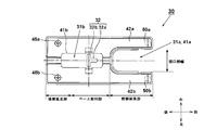
- openings 31a and 41a are formed on the front side of the portion overlapping with the base mounting portion 2d, and front side extensions (guide surfaces 42a and 42b) are elongated on the left and right sides and extend forward. It is formed. Screws and screw holes do not exist on the guide surfaces 42a and 42b on the left and right sides of the openings 31a and 41a.
- the buffer mechanisms 50a and 50b are provided almost in the vicinity of the front ends of the guide surfaces 42a and 42b as indicated by dotted lines.
- An opening 41 b is formed near the center of the base plate 41.
- the opening 41b allows access to the inner wall portion of the protruding portion 31b of the base base 31, and a T-shaped screw hole 32 is formed at that position of the base base 31.
- the base mounting portion 2d is provided with a bolt hole through which a bolt 48 (see FIG. 8) passes.
- the screw hole 32 includes a first hole portion 32a extending in the longitudinal direction of the base mounting portion 2d, and a first hole portion. On the other hand, it is composed of a second hole 32b extending in the arc direction in the vertical direction, and is configured in a substantially T shape.
- the base base 31 and the base plate 41 are screwed by two screws 45a and 45b in the region of the rear extension portion on the rear side of the base mounting portion.
- the fixing points by the screws 45a and 45b are arranged on one side (here, the rear side) in the front-rear direction with respect to the center of gravity position (described later) of the jigsaw.
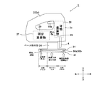
- FIG. 3 is a schematic diagram for explaining the vibration damping operation by the base 30 of the jigsaw 1 according to the embodiment of the present invention.
- a fixed heavy object 27 centered on the motor 6 is disposed in the motor housing portion 2 b, and the motion conversion mechanism 10 serving as a vibration generation source is provided in the motion conversion mechanism housing portion 2 c on the front side thereof.
- a movable heavy object 28 such as a balance weight 16, a plunger 14 or the like (see FIG. 8) is accommodated.
- a force for moving the housing 2 upward or downward at the front portion of the center of gravity 29 acts greatly. That is, when the movable heavy object 28 reciprocates, the housing 2 swings around the center of gravity 29.
- the center of gravity 29 is positioned near the trigger lever 19a, and the base mounting portion 2d fixes the base 30 to the center of gravity 29 at a lower position.
- a buffering effect is obtained between the base base 31 and the base plate 41 of the base 30.
- a buffer using a spring is used so that the base plate 41 can swing as a swing point on one end side (here, the rear side) of the base base 31 and on the other end side (here, the front side).
- the mechanism is held by the mechanisms 50a and 50b. That is, since the base plate 41 is fixed to the base base 31 attached to the base attaching portion 2d by the screws 45a and 45b on the rear side, the base base 31 and the base plate 41 are in contact with each other at the screwed portion. On the other hand, the front side of the base plate 41 is held so as to be swingable by the buffer mechanisms 50a and 50b.
- the base plate 41 becomes a movable portion whose front side portion can swing in the vertical direction with the fixed portion fixed by the screws 45a and 45b on the rear side as fulcrums (or support surfaces).
- the housing 2 and the base base 31 swing with respect to the base plate 41 around the fixed portion on the rear side, so that vibration transmitted from the base plate 41 to the workpiece is reduced.
- the vibration transmitted from the housing 2 side to the material to be cut or the reaction force transmitted from the material to be cut to the housing 2 side is greatly attenuated.
- one side of the base plate 41 (the contact surface of the base 30 with the material to be cut) in the direction in which the fixed heavy object 27 and the movable heavy object 28 are arranged (the direction in which the motor 6 and the plunger 14 are arranged) is arranged with respect to the housing 2. It is a feature of the present invention that the other side which is fixed and separated from one side is held so as to be movable with respect to the housing 2.
- the base plate 41 is provided with the buffer mechanisms 50a and 50b near the front end, and the fixing point (fulcrum) when the base plate 41 swings is provided near the rear end.
- a sufficient distance could be secured and good buffer performance could be realized.
- the damping effect is great.
- a fixing point for swinging the base plate 41 is provided immediately below the handle portion 2a, the pressing force during the operation can be easily transmitted to the material to be cut to ensure operability and effectively vibrate. It was possible to reduce.
- the shock absorbing mechanisms 50a and 50b are achieved by metal coil springs.
- the present invention is not limited to coil springs, but good elastic effects and vibration control effects such as disc springs, leaf springs, rubber dampers, and other elastic bodies. You may implement
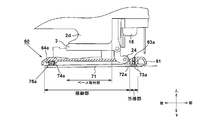
- the mounting method of the base base 61 and the base plate 71 in the base 60 is reversed from the first embodiment in the front-rear direction.
- the base plate 71 is fixed to the base base 61 on the front side by two screws 73a and 73b (73b is not visible in the figure).
- the base plate 71 is formed with an annular groove 72 a for accommodating the head of the screw 73 a so that the head of the attached screw 73 a does not protrude from the outer surface of the base plate 71.
- a portion of the base base 61 that is fixed by the screws 73a and 73b serves as an abutting portion that comes into contact with the base plate in a predetermined region of a screw boss shape.
- the rear side of the contact portion is disposed so that the base base 61 and the base plate 71 are separated from each other, and is held by buffer mechanisms 75a and 75b (75b is not visible in the drawing).
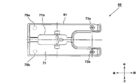
- the buffer mechanisms 75a and 75b are provided at two locations, and the positions for providing them may be arranged at substantially the same positions as the screws 45a and 45b shown in FIG. In FIG. 5, the positions of the buffer mechanisms 75a and 75b are indicated by dotted lines.
- the structure of the buffer mechanisms 75a and 75b can be realized by using coiled metal springs 74a and 74b.
- the springs 74a and 74b are fitted into cylindrical holes 64a and 64b (64b is not visible in FIG. 4) formed on the lower side of the base base 61.
- the buffer mechanisms 75a and 75b are located on the rear side of the lower region (base mounting portion) of the base mounting portion 2d of the housing 2 and are fixed by screws 73a and 73b.
- the lower side area (base mounting part) of the base mounting part 2d is set to the front side. In this way, the length of the swinging portion can be made sufficiently long with respect to the abutting portion serving as the swinging fulcrum, so that the swinging radius can be increased, and the small springs 74a and 74b can be used. A good buffering effect can be obtained.
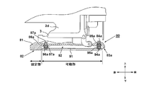
- a lower surface 82 as a contact surface having a predetermined area is formed on one side of the base base 81 in the front-rear direction.
- a base plate 91 separated from the base base 81 and held by a buffer mechanism is disposed on the front side of the lower surface 82.
- the bottom surface 82 of the base base 81 serving as a fixing portion is a substantially rectangular shape that is elongated in a direction orthogonal to the cutting direction (here, the left-right direction), and serves as a fulcrum when the jigsaw 1 swings in a vertical plane including the cutting direction.
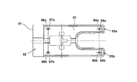
- the base plate 91 which is a movable part is fixed near the four corners by screws 84a, 84b, 87a, 87b and springs 95a, 95b, 97a, 97b (however, 95b, 97b cannot be seen in FIG. 6).
- the screws 84a, 84b, 87a, 87b pass through a through hole (smaller than the diameter of the screw head) formed in the base base 81, but no screw thread is formed in the through hole, and the screw 84a, On the 84b, 87a, and 87b sides, no thread is formed in the vicinity of sliding with the through hole.
- the screws 84a, 84b, 87a, 87b are threaded only in the vicinity of the tip in the axial direction, and are screwed into the screw holes 94a, 94b, 96a, 96b provided in the base plate 91.
- a space 92 is formed between the base base 81 and the base plate 91.
- These screws 84a, 84b, 87a, 87b are members for holding the base plate 91 on the base base 81 by the respective heads, but the base plate 91 approaches the base base 81 as much as tightened,
- the springs 95a, 95b, 97a, 97b can be compressed to the maximum.
- the operator can adjust the compression amount of the spring by adjusting the tightening amount of the screw, and can adjust (disappear) the vibration reducing ability of the buffer mechanism according to the work form. It can be set as the reciprocating tool according to work.
- FIG. 7 is a bottom view of a jigsaw base 80 according to a third embodiment of the present invention.
- the outer edge profile of the lower surface of the base 80 is similar to the bases 30, 60 of the first and second embodiments.
- the portion corresponding to the lower surface 82 of the base 80 is molded integrally with the base base 81, so that the force when the operator presses the jigsaw 1 against the workpiece is effectively transmitted. it can.
- the portion on the front side of the lower surface 82 is the base plate 91 whose four corners are held by the buffer mechanism, it is possible to achieve an effective vibration control action.
- the compression side of the swing range of the base plate 91 on the springs 95a and 95b side is limited by the front end portions 83a and 83b of the guide portion of the base base 81 coming into contact with the material to be cut.
- the compression side of the swing range of the base plate 91 is limited by the lower surface 82 of the base base 81.
- the lower surface 82 that is a fixed surface is not limited to a complete plane, and may have a curved surface that follows the movement of the base plate 91 that is a movable surface.
- the base plate screw fixing method used in the third embodiment can be applied to the first and second embodiments.
- the vibration reduction function of the buffer mechanism can be adjusted in the same manner as in the third embodiment by changing the amount of compression of the spring (the amount of the protrusion S).
- the base base 81 is not provided with the lower surface 82 so that only the portion of the base plate 91 is in contact with the material to be cut, and the base plate 91 is configured to hold the four corners by the buffer mechanism, and in the space 92 portion,
- the base plate 91 may be configured to be movable in a state in which a projection serving as a fulcrum protrudes from the base base 81 side to the base plate 91 side and the fulcrum portion is in contact with the base plate 91.
- the present invention has been described with reference to an example used for a jigsaw base.
- the present invention may be applied to the method for holding the base base and the base plate.
- the present invention may also be applied to a reciprocating tool having a base member pressed against a material to be cut or a non-abrasive material.
Landscapes
- Engineering & Computer Science (AREA)
- Mechanical Engineering (AREA)
- Sawing (AREA)
Abstract
往復動に起因する振動が、ベース部から被切断材に伝わることを低減できる往復動工具を提供する。ハウジング2の下部にベース部30を設けた往復動工具1において、ベース部30はベース基台31とベースプレート41を有する。ベース基台31とベースプレート41は、後方側が左右2本のネジ45aにて直接固定された当接部となり、前方側が左右2カ所に設けられる緩衝機構50aを介して保持された揺動部となる。ベース基台31とベースプレート41は揺動部となる前側部分において非接触状態で保持されるので、良好な制震効果を得ることができ、往復動に起因する振動の伝達を抑制でき、切断精度が向上する。
Description
本発明は往復動するブレードによって被切断材を切断する往復動工具に関し、特にブレードの往復動によりベース部に伝わる振動を低減させた往復動工具に関する。
従来、駆動源としてのモータの回転運動を先端工具の往復運動に変換して作業を行う往復動工具においてジグソーが知られている。ジグソーは、ハウジングの本体部分の下部に取り付けられた水平状のベース部を被切断材に当接させた状態で、本体部分を切断方向となる前方側に移動させながら、往復動するブレードにより被切断材の切断を行うものである(例えば、特許文献1参照)。
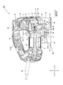
ここで図8の縦断面図を用いて従来のジグソー101の構造を説明する。ハウジング2は樹脂等の成型によって左右2分割式に形成された側面視で横向きに倒した略D字状の外見を有する。ハウジング2は回転軸7が水平方向になるように配置されるモータ6を収容するモータ収容部2bと、モータ収容部2bの前方側において鉛直方向に長い所定の空間を有する運動変換機構収容部2cと、運動変換機構収容部2cの上側とモータ収容部2bの後方側を上方側に接続するように延びるハンドル部2aを含んで構成される。ハンドル部2aは作業者が片手で把持する部分であって、その内側にはモータ6のオン又はオフを切替えるトリガスイッチ19が収容され、ハンドル部2aの下側には作業者が操作するトリガレバー19aが設けられる。ハンドル部2aの前方側には、モータ6の回転速度を調整するための速度調整ダイヤル25が設けられる。
モータ収容部2b内にはモータ6が設けられ、ハウジング2の後端付近には商用電源を供給するための電源ケーブル26が設けられる。モータ6の回転軸7には冷却ファン5が固定され、その前方側の先端部分には、ピニオンギヤ7aが設けられる。モータ6が回転することにより冷却ファン5も回転し、ハウジング2に形成された図示しない外気導入口から外気をハウジング2の内部に導入し、モータ6や運動変換機構10等の冷却を行う。ピニオンギヤ7aは、偏心カムと一体形成されたギヤ部9と噛合する。ギヤ部9は回転軸8を中心に回転し、モータ6の動力を変換する動力変換機構を構成し、ギヤ部9の後方側は回転軸7に対して同心に回転する平ギヤであり、その前方側には偏心カム9bが形成される。
偏心カム9bの外周形状は円形であり、偏心カム9bの中心は回転軸7の回転中心から偏心するように形成される。偏心カム9bの周囲にはバランスウエイト16が配置される。バランスウエイト16は金属の一体成形であって、偏心カム9bを収容する長穴16aが形成される。長穴16aの長軸は水平方向に延びるように形成され、偏心カム9bが長穴16aの内部で回転することによって、それらの当接箇所が変化してバランスウエイト16が上下方向に移動する。バランスウエイト16は、上下方向に延びる直線状のスリット(図示せず)によって移動方向が上下方向に規制される。
偏心カム9bの前方側には、ホルダ11がねじを用いて固定されている。ホルダ11は鋼材により一体成形されたもので、ニードル軸受12を介して水平方向に延びるコネクティングレール13が接続される。コネクティングレール13は、鋼材を押し出し成形したものであってプランジャ14の上端側に保持される。ニードル軸受12が回転軸7の回転中心から偏心するように回転することによって、水平方向に延びるコネクティングレール13の内側で接触位置が水平方向に変化することによりプランジャ14を上下方向に往復移動させる。ニードル軸受12の偏心位置は、偏心カム9bの偏心位置と逆位相(回転角にして180度離れる)に配置され、プランジャが上昇するときにはバランスウエイト16が下降し、プランジャが下降するときにはバランスウエイト16が上昇するようにして、プランジャ14とその下方に取り付けられるブレード(図示せず)の移動に伴う反動をバランスウエイト16により打ち消すようにした。プランジャ14の下端には、ブレードを取り付けるためのブレード保持部15が設けられる。ブレード保持部15の前方側には切断紛などの飛散防止用のチップカバー35が設けられる。
ブレード保持部15は、プランジャ14の先端部(下端部)に設けられ、ブレードを着脱可能に保持する。プランジャ14は略円柱形状をなし、ハウジング2に上下方向に往復動可能かつ回動可能に支持される。上下方向略中央部分において、プランジャガイド18によって上下方向に摺動可能に支持される。プランジャガイド18は、その外周部においてスプリング17により径方向に付勢されることにより、プランジャ14の前後方向のオービタル動作を許容する。偏心カム9aにはオービタルカム21aが接続され、ギヤ部9が回転するとオービタルカム21aが上下動し、その下端部に一体に設けられた作用片21bが逆L字状のローラホルダ22の一端側を押圧または開放し、ローラホルダ22は揺動軸23を中心に揺動移動されることによりローラホルダ22の他端側に設けられたローラ24を前後方向に移動させる。ローラ24は、ローラホルダ22の前端部に位置していて、ローラ24を回転可能に支承する。ローラ24は外周面の左右中央に図示しないブレードを案内するための周方向に連続した溝が形成されており、これらオービタル機構部20により、ブレードの刃先側と反対側の背部を押圧することによりオービタル動作を可能とした。
ベース130は、長手方向が切断方向と一致するように、ボルト48を介してモータ収容部2bの底面側に、ギヤカバー3の一部を介在させて固定される。ベース130は、ジグソー101を安定してがたつかないように被切断材に押し当てることができるように比較的大きめの面積を有する底面を有する。ベース130はベース基台131とベースプレート141から主に構成される。ベース基台131の上面は、ハウジングのベース取付部2dにボルト48にて固定するための円弧状の突出部分131aが形成される。ベース基台131の下側(反ハウジング側)には、被切断材と対向するベースプレート141が設けられる。通常、ジグソー101は、ハウジング2の分割面がベース130に対して垂直に位置しており、被切断材の垂直切断を行うが、ハウジング2をベース130に対して傾斜させて任意の角度で被切断材を切断することも可能である。
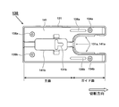
次に図9を用いてベース130の底面部分の形状を説明する。ベース130は主面部分の前方側にブレード(図示せず)を挿通させるための開口部131a、141aが設けられる。開口部131a、141aは前方側に開口するように下面視で略コ字状に形成されるもので、この開口部131a、141a内を下方向に延出するブレードによる切断方向の左右両側に平行に伸びる細長い形状のガイド面が形成される。ベース基台131の中央付近の略半円筒状に上方に隆起するように形成された部分は、ボルト48(図8参照)を介してハウジング2に固定するためのネジ孔131bが形成される。ベースプレート141には、中央に略長方形に切り抜かれた開口141bが形成され、ボルト48(図8参照)の締め付けを可能としている。
ベースプレート141の外縁形状は、ベース基台131の外縁形状に対応した相似形であり、下面視においてベース基台131よりも僅かに小さい外縁を有する。ベースプレート141は4つのネジ134a、134b、135a、135bによってベース基台131にネジ止めされる。ネジ134a、134bの後方側であって、ベースプレート141の底面には、被切断材との間の摩擦力を低減するための低摩擦剤136a、136bが塗布又は貼付けられる。
従来のジグソーにおいては、被切断材の上面にジグソーを安定して位置づけるために、ハウジングの下側にベース部が設けられる。ベース部の底面は平面状であり、平面部分を被切断材に押し当てながら切断作業を行う。通常、ジグソーは、ブレードが往復動する際に生ずる振動を打ち消すためのバランスウエイトを用いたバランサを有する。しかしながら、バランサだけでは振動を完全に打ち消すことができないため、往復動に伴う振動がベース部から被切断材に伝わる。この振動の伝達は切断精度を向上させる上での阻害要件となるため、ベースプレートから被切断材に伝わる振動をできるだけ抑制した方が好ましい。しかし、単に振動を抑制するための緩衝材をベースプレートとベース部との間に設けると、ハンドル操作がベースプレートに伝達されにくく操作性が悪くなってしまう。また、操作性を確保するために硬い部材を緩衝材に用いると振動低減の効果が薄れてしまう。
本発明は上記背景に鑑みてなされたもので、その目的は、往復動に起因する振動がベース部から被切断材に伝わることを効果的に低減できる往復動工具を提供することにある。
本願において開示される発明のうち代表的なものの特徴を説明すれば次の通りである。本発明の一つの特徴によれば、ハウジングに収容されるモータと、先端部にブレードを装着可能であってモータにより駆動され往復動するプランジャと、ハウジングに取付けられハウジングと共に被切断材上を移動するように設けられたベース部と、を有する往復動工具において、ベース部は、ハウジングに保持されるベース基台とベース基台の反ハウジング側に取り付けられるベースプレートによって構成され、ベース基台とベースプレートとが接触する当接部と、ベース基台が弾性体を介してベースプレートを支持する弾性支持部と、を有し、当接部と弾性支持部とは、モータとプランジャが並ぶ方向において離間して設けられ、ベースプレートは当接部を支点として揺動可能であり、弾性支持部においてベース基台に対して近接・離間するように揺動するようにした。ベース基台を取り付けるためのベース取付部をハウジングの下側に設け、切断方向にみてベース基台の中央付近にてベース取付部にベース基台が取り付けられ、当接部と弾性支持部は、下面視においてベース取付部の位置と重複しない領域内に配置される。さらに、ベースプレートは、ブレードの通過する開口部よりも後方側に位置する主面と、開口部の両側において前方側に平行して延びる2本のガイド面を有し、当接部は主面又はガイド面のいずれか一方側に設け、他方側に弾性支持部が配置される。
本発明の他の特徴によれば、ベースプレートは可撓性を有する金属板材であって、弾性支持部においてスプリングを用いてプランジャの移動方向に金属板材の板厚以上の移動ストロークを確保した。また、当接部はネジによってベース基台の下面にベースプレートが接するように固定され、ベース取付部に対面する領域においてベース基台とベースプレートは隙間を持って非接触状態に保たれる。さらに、ハウジングは、回転軸が水平方向になるようにモータを収容するモータ収容部と、モータ収容部の前方側にて鉛直方向に延びプランジャを収容する運動変換機構収容部と、運動変換機構収容部の上側とモータ収容部の後方側が上方で接続されるようにして形成したハンドル部を有する側面視で横に倒した略D字状であって、当接部のネジによる固定箇所が往復動工具の重心位置に対して前後方向の一方側に位置し、振動発生源たる運動変換機構と弾性支持部による保持箇所が往復動工具の重心位置に対して前後方向の他方側に位置するようにした。
本発明のさらに他の特徴によれば、運動変換機構には、プランジャと、プランジャと逆位相で往復動することによって振動を打ち消すためのバランサと、プランジャとバランサをモータの回転力によって往復移動させるための動力変換機構を有する。また、ベース基台が水平に位置づける状態でハウジングを持ち上げたときに、ベースプレートのベース基台から下方向への突出量は、切断方向にみて、ベース基台とベースプレートの当接部で小さく、弾性支持部側で大きくなるようにした。尚、ベースプレートはバネ性を有する金属板にて形成した。
本発明によれば、ハウジングの本体側で発生した振動はベースプレートがベース本体に対して揺動することで被切断材側に伝わることを大幅に抑制できる。また、ベースプレートと揺動側に弾性体を介在させたので被切断材に伝わる振動が大幅に抑制され、切断精度を向上させることができる。さらに、作業者にとってもハウジングの振動が抑制されるので切断作業の疲労を大幅に低減できる。
以下、本発明の実施例を図面に基づいて説明する。なお、以下の図において、同一の部分には同一の符号を付し、繰り返しの説明は省略する。また、本明細書においては、前後、上下の方向は図中に示す方向であるとして説明する。
図1は本発明の実施例に係る往復動工具の一例たるジグソー1の右側面図である。本実施例のジグソー1において、ハウジング2と、その内部に収容される本体部は、図8で説明したジグソー101の内部構造と同じである。本実施例では、ハウジング2のベース取付部2dに装着されるベース部(ベース30)の構成を改良した。ベース30は、ベース取付部2dに装着されるベース基台31と、ベース基台31にて固定されるベースプレート41により主に構成される。ベースプレート41はベース基台31の下側(反ハウジング側)に配置され、被切断材に当接する接地面を形成し、切断作業時においては被切断材の上面を摺動しながら移動する。底面視におけるベースプレート41の形状は、従来のベースプレート141とほぼ同等の可撓性を有する金属板材であるが、ベースプレート141のベース基台31への取り付け方向が従来の構造とは異なる。ベースプレート41は後方側では左右2本のネジ45a、45b(図では45bは見えない)によって固定される。これは従来例と同じ固定方法である。一方、ベースプレート41の前方側では、スプリング51aを有する緩衝機構50aを介在させてベース基台31とベースプレート41が上下方向、即ちブレードの往復移動方向と同方向に可動となるように構成した。また、図1では見えないが緩衝機構50bも設けてブレードが上下動する左右両側において緩衝機構50a、50bを配置した。
このように緩衝機構50a、50bを設けてベースプレート41の前方側を保持したので、作業者がハンドル部2aを把持してジグソー1を持ち上げた際に、ベースプレート41の下面とベース基台31の前側下端位置は、距離Sだけ隔てることになる。この距離Sは、後方側のベースプレート41の下面からベース基台31の後側下端位置の突出量S1よりも大きくなる。さらに、突出量Sをベースプレートの板厚tよりも大きくなる程度に確保して、ベースプレート41の前側部分が、緩衝機構50aによってベース基台31に対して十分なストローク量、例えば板厚t以上の移動ストロークを確保できるようにした。スプリング51aを圧縮してベースプレート41の前側部分が上方に移動すると、ベース基台31の前側下端部が被切断材に当接するので、それ以上のベースプレート41の揺動は阻止され、スプリング51aの過度な圧縮による破損を抑制できる。
ベースプレート41の後方側においては、ネジ45a、45b(45bは図2参照)によってベース基台31に固定されるうえ、ベース基台31の後端の下方位置とベースプレート41の後端下方位置が、僅かな段差による突出量S1(但しS1<ベースプレート41の板厚t)となるようにした。このように突出量S1を設けたことにより切断作業時には被切断材に対してベースプレート41が当接することになる。ベース基台31は例えばアルミ合金の成形品によって構成し、ベースプレート41はステンレス、アルミ合金、または、ある程度のバネ性を有する金属板をプレスしたものである。スプリング51aは、ジグソー1を単に被切断材においた際には、ある程度縮むものの完全に沈まないようにする。そして、作業者が切断作業を行うときにハンドル部2aを把持してジグソー1を下方向に押しつけた際に、スプリング51aが更に縮んだ状態(緩衝機構50aの実用状態)になるようにした。このとき、スプリング51aのバネ定数は、通常の作業状態(押付力)であればベース基台31の前側下端部が被切断材に当たらないような値に設定してある。このようにベース30のうち、ベースプレート41の切断方向の一方側(ここでは後方側)を、ベース基台31とベースプレート41が面接触するように固定された当接部にして、他方側(ここでは前方側)をベース基台31とベースプレート41が所定の距離を隔てるように隔てた揺動部としたので、ジグソー1の本体側から被切断材側に伝わる振動、又は、被切断材側から本体側に伝わる反動の影響を、緩衝機構50aによる緩衝効果によって吸収することができる。また、金属製のベースプレート41自体の板バネ効果も加わって、反動の影響を一層吸収することができる。
ベースプレート41は、ネジ45a、45bで固定される固定点付近では左右方向ほぼ全面においてベース基台31と接する当接部となる。この構造とするために、ベース基台31のネジ45a、45b付近は前後方向に所定の長さを有する平面状になっている。この平面状部分は、左右方向に辺部まで延びて下面視で細長い長方形状に形成される。従って、この長方形状の面部分が揺動するベースプレート41の揺動軸又は揺動支点としての機能を果たす。当接部の前方側であってベース取付部2dの直下部分では、ベース基台31とベースプレート41は所定の空間43を有している。ベース取付部に対面する領域において前記ベース基台と前記ベースプレートは、隙間を持って非接触状態に保たれ、ハウジング2のベース取付部2dに対面する領域(直下部分)とその前側部分においては、ベース基台31とベースプレート41の間は隙間を持って非接触状態に保たれる。このように、ベース30の前方側ではベース基台31とベースプレート41が上下方向に完全に離れた状態となっているので、この部分ではベースプレート41が上下方向、即ちプランジャ14(図8参照)の揺動方向と同じ方向に揺動可能となる。
緩衝機構50aはベース基台31の下面とベースプレート41の上面の間に、金属製のコイル式のスプリング51aを介在させたものである。スプリング51aを設ける位置は、図9で示したネジ134a、134bよりも更に前方側に配置した。図1ではベース基台31とスプリング51aの固定、ベースプレート41とスプリング51aの固定の方法の図示を省略しているが、ベース基台31の下面側にスプリング51aを嵌合させるための凹状の窪みを設け、ベースプレート41側にスプリング51aの内径部分に嵌合させるための凸状の円柱突起を設けることにより、ベース基台31又はベースプレート41からスプリング51aが抜け落ちないように構成すれば良い。また、図1では図示していないが、緩衝機構50b側の構成や用いられるスプリング51bも、緩衝機構50a側の構成と同様である。尚、スプリング51a、51bの固定の仕方は任意であり、その他の固定方法を用いるようにしても良い。
次に図2を用いてベース30の底面形状を説明する。ベース30の底面形状は図9で示した従来の構成とほぼ同形である。前後方向に見たときにベース取付部2dと重複する部分の前方側には、開口部31a、41aが形成されその左右両側には細長く前方側に延びる前側延長部(ガイド面42a、42b)が形成される。開口部31a、41aの左右両側のガイド面42a、42bにおいては、ネジ及びネジ穴が存在しない。緩衝機構50a、50bは、点線で示すようにガイド面42a、42bのほぼ前端付近にそれぞれ設けるようにした。
ベースプレート41の中央付近には開口41bが形成される。この開口41bからベース基台31の突出部31bの内壁部分にアクセス可能であり、ベース基台31のその位置にはT字状のネジ孔32が形成される。ベース取付部2dにはボルト48(図8参照)が貫通するボルト孔が設けられており、ネジ孔32はベース取付部2dの長手方向に延びた第1孔部32aと、第1孔部に対して垂直方向に円弧方向に延びた第2孔部32bからなり略T字状に構成されている。一方、ベース取付部よりも後方側の後方延長部の領域内において2本のネジ45a、45bによりベース基台31とベースプレート41がネジ止めされる。ネジ45a、45bによる固定箇所はジグソーの重心位置(後述)に対して前後方向の一方側(ここでは後側)に配置される。
図3は、本発明の実施例に係るジグソー1のベース30による振動減衰動作を説明するための模式図である。ジグソー1のハウジング2の内部には、モータ6を中心とした固定重量物27がモータ収容部2bに配置され、その前方側の運動変換機構収容部2cには、振動発生源たる運動変換機構10やバランスウエイト16、プランジャ14等(図8参照)の可動重量物28が収容される。可動重量物28は上下方向に可動であり、ブレード4の動きに合わせて同方向又は反対方向に移動するので、重心29よりも前側部分でハウジング2を上向き又は下向きに移動させる力が大きく作用する。つまり、可動重量物28が往復運動すると、ハウジング2が重心29を中心に揺動する。重心29はトリガレバー19aの真下付近に位置し、さらに重心29に下側位置にてベース取付部2dがベース30を固定する。
本実施例ではベース30のベース基台31とベースプレート41との間で緩衝効果を得るように構成した。この際、ベース基台31の一端側(ここでは後方側)を支点として、他端側(ここでは前方側)にてベースプレート41が揺動点として揺動可能なように、スプリングを用いた緩衝機構50a、50bにて保持する。つまり、ベース取付部2dに取り付けられるベース基台31に対して、ベースプレート41は後方側においてネジ45a、45bにより固定されるため、ネジ止め部分にてベース基台31とベースプレート41が接する。一方、ベースプレート41の前方側においては、緩衝機構50a、50bによって揺動可能に保持される。この結果、ベースプレート41は後方側のネジ45a、45bによって固定される固定部を支点(又は支持面)として、前方側部分が上下方向に揺動可能な可動部となる。このように振動発生源たる運動変換機構と弾性支持部による保持箇所が、ジグソーの重心位置に対して前後方向の他方側に位置することにより可動重量物28が上下方向に往復移動してもベース30においては、後方の支点を揺動中心として前方側が上下方向に揺動する。すなわち可動重量物28の往復運動中は、後方側の固定部分を中心にハウジング2とベース基台31がベースプレート41に対して揺動するので、ベースプレート41から被切断材に伝達される振動が低減でき、ハウジング2側から被切断材側に伝わる振動、又は被切断材側からハウジング2側に伝わる反力が大幅に減衰される。この様に、固定重量物27と可動重量物28が並ぶ方向(モータ6とプランジャ14が並ぶ方向)におけるベースプレート41(ベース30の被切断材との接触面)の一方側をハウジング2に対して固定し、一方と離間した他方側をハウジング2に対して移動可能なように保持することが本発明の特徴である。
以上、本実施例では、ベースプレート41が前端付近に緩衝機構50a、50bを設け、ベースプレート41の揺動する際の固定点(支点)を後端付近に設けたので、支点から揺動点までの距離を十分確保することができ、良好な緩衝性能を実現することができた。特に、揺動支点と揺動点との距離をベース30の前後方向の長さをほとんど使ったのでその減衰効果は大きい。また、ハンドル部2aの直下にベースプレート41の揺動する際の固定点を設けたので、作業時の押付力が被切断材に伝達しやすくして操作性を確保しつつ、効果的に振動を低減することができた。尚、本実施例では緩衝機構50a、50bを金属製のコイルバネによって達成したが、コイルバネだけに限られずに、皿ばね、板バネ、ゴムダンパ、その他の弾性体など、良好な弾性効果と制震効果を有する弾性部材を用いて実現しても良い。
次に図4及び図5を用いて本発明の第二の実施例を説明する。第二の実施例ではベース60においてベース基台61とベースプレート71の取り付け方法、特に支点側と揺動点側の関係を前後方向に見て第一の実施例とは逆になるようにした。ベースプレート71は前方側においてベース基台61に2本のネジ73a、73b(73bは図では見えない)によって固定される。ベースプレート71にはネジ73aの頭部を収容するための円環状の溝部72aが形成され、取り付けられたネジ73aの頭部がベースプレート71の外面よりも突出しないように構成される。ネジ73a、73bにて固定される部分のベース基台61部分は、ネジボス状の所定の領域でベースプレートと接触する当接部となっている。当接部の後方側は、ベース基台61とベースプレート71が離れるように配置され、緩衝機構75a、75b(図では75bは見えない)により保持される。緩衝機構75a、75bは2カ所であって、それらを設ける位置は図2で示したネジ45a、45bとほぼ同じ位置、またはやや後方側に配置すれば良い。図5では緩衝機構75a、75bの位置を点線にて示している。緩衝機構75a、75bの構成はコイル状の金属製のスプリング74a、74bを用いて実現できる。スプリング74a、74bは、ベース基台61の下側に形成される円筒形の穴部64a、64b(図4では64bは見えない)に嵌合される。
ここで緩衝機構75a、75bは、図5に示すようにハウジング2のベース取付部2dの下側領域(ベース取付部)よりも後方側になるようにし、ネジ73a、73bにて固定する部分はベース取付部2dの下側領域(ベース取付部)よりも前側にした。このようにすれば、揺動支点となる当接部に対して揺動部の長さを十分長くすることができるので、揺動半径を大きくとることができ、小型のスプリング74a、74bにて良好な緩衝効果を得ることができる。
次に図6及び図7を用いて本発明の第三の実施例を説明する。第三の実施例ではベース80において、ベース基台81の前後方向の一方側に所定の面積を有する当接面たる下面82を形成した。また、下面82の前方側において、ベース基台81から緩衝機構によって分離して保持されたベースプレート91を配置した。この結果、ベース80のうち、後方側の固定部においてはベース基台81が直接被切断材に当接し、前方側の可動部においてはベースプレート91の前面が被切断材に当接する。この考えは、ベース80のうち一端側(ここでは後方側)において揺動支点として、他端側(ここでは前方側)を揺動部にするという点で、第一の実施例と考えと共通する。しかしながら、第三の実施例では固定部と、緩衝機構によって可動する可動部を分離して構成した。固定部となるベース基台81の下面82は、切断方向とは直交する方向(ここでは左右方向)に細長い略長方形として、ジグソー1が切断方向を含む鉛直面状で揺動する際の支点として作用する。
可動部たるベースプレート91は、四隅付近でネジ84a、84b、87a、87bとスプリング95a、95b、97a、97b(但し図6では95b、97bは見えない)によって固定される。ネジ84a、84b、87a、87bは、ベース基台81に形成される貫通穴(ネジ頭部の径より小さい)を貫通するが、貫通穴にはネジ山が形成されておらず、ネジ84a、84b、87a、87b側にも貫通穴と摺動する付近にはネジ山が形成されていない。つまり、ネジ84a、84b、87a、87bは軸方向先端付近だけにネジ山が形成され、ベースプレート91に設けたネジ穴94a、94b、96a、96bと螺合する。このように配置した際に、ベース基台81とベースプレート91との間は空間92が形成される。これらのネジ84a、84b、87a、87bは、それぞれの頭部によってベースプレート91をベース基台81に保持させるための部材であるが、締めこんだ分だけベースプレート91がベース基台81に接近し、スプリング95a、95b、97a、97bが最大まで圧縮させることができる。つまり、作業者はネジの締め込み量を調整することでスプリングの圧縮量を調整可能であり、作業形態に合わせて緩衝機構の持つ振動低減能力を調節(消失)させることができるため、多様な作業に合わせた往復動工具とすることができる。
図7は本発明の第三の実施例に係るジグソーのベース80の底面図である。ベース80の下面の外縁輪郭は、第一及び第二の実施例のベース30、60と同様であることが理解できるであろう。第三の実施例によればベース80のうち下面82に相当する部分がベース基台81と一体に成型されるので、作業者がジグソー1を被切断材に押しつける際の力を効果的に伝達できる。一方で、下面82よりも前側の部分が緩衝機構によって四隅を保持されたベースプレート91としたので、効果的な制震作用を奏することが可能となる。スプリング95a、95b側においてベースプレート91の揺動範囲の圧縮側は、ベース基台81のガイド部分の前端部分83a、83bが被切断材に当接する事により制限される。スプリング97a、97b側においてにおいてベースプレート91の揺動範囲の圧縮側は、ベース基台81の下面82により制限される。尚、固定面たる下面82は完全な平面だけに限られずに、可動面たるベースプレート91の動きに追従するような曲面を有していても良い。
以上、本発明を実施例に基づいて説明したが、本発明は上述の実施例に限定されるものではなく、その趣旨を逸脱しない範囲内で種々の変更が可能である。例えば、第三の実施例において使用されたベースプレートのネジによる固定方法は第一、第二の実施例にも適用可能である。ベースプレートの可動部をネジによって保持させることで、スプリングの圧縮量(突出量Sの大きさ)を変化させて第三の実施例と同様に緩衝機構の持つ振動低減機能の調節が可能となる。また、ベース基台81に下面82を設けないようにして、ベースプレート91の部分だけで被切断材に接するようにし、ベースプレート91は緩衝機構によって四隅を保持するように構成し、空間92部分に、支点となる突起をベース基台81側からベースプレート91側に突出させて、その支点部分をベースプレート91に接触させた状態でベースプレート91が可動状態となるように構成しても良い。また、上述の実施例ではジグソーのベースに用いられる例で本発明を説明したが、セーバソーや丸鋸に用いられるベースにおいて、上記ベース基台とベースプレートの保持方法に適用しても良いし、その他の被切断材又は非研磨材に押し当てるベース部材を有する往復動工具に適用しても良い。
1…ジグソー、2…ハウジング、2a…ハンドル部、2b…モータ収容部、2c…運動変換機構収容部、2d…ベース取付部、3…ギヤカバー、4…ブレード、5…冷却ファン、6…モータ、7…回転軸、7a…ピニオンギヤ、8…回転軸、9…ギヤ部、9a,9b…偏心カム、10…運動変換機構、11…ホルダ、12…ニードル軸受、13…コネクティングレール、14…プランジャ、15…ブレード保持部、16…バランスウエイト、16a…長穴、17…スプリング、18…プランジャガイド、19…トリガスイッチ、19a…トリガレバー、20…オービタル機構部、21a…オービタルカム、21bv作用片、22…ローラホルダ、23…揺動軸、24…ローラ、25…速度調整ダイヤル、26…電源ケーブル、27…固定重量物、28…可動重量物、29…重心、30…ベース、31…ベース基台、31a…開口部、31b…突出部、32…ネジ孔、32a…第1孔部、32b…第2孔部、35…チップカバー、41…ベースプレート、41a…開口部、41b…開口、42a,42b…ガイド面、43…空間、45a,45b…ネジ、48…ボルト、50a,50b…緩衝機構、51a,51b…スプリング、60…ベース、61…ベース基台、71…ベースプレート、73a,73b…ネジ、74a,74b…スプリング、75a,75b…緩衝機構、80…ベース、81…ベース基台、82…下面、84a,84b…ネジ、91…ベースプレート、92…空間、94a,94b,96a,96b…ネジ穴、95a,95b,97a,97b…スプリング、101…ジグソー、130…ベース、131…ベース基台、131a…開口部、131b…ネジ孔、134a,134b…ネジ、135a,135b…ネジ、136a…低摩擦剤、141…ベースプレート、141b…開口
Claims (11)
- ハウジングと、前記ハウジングに収容されるモータと、先端部にブレードを装着可能であって前記モータにより駆動され往復動するプランジャと、前記ハウジングに取付けられ前記ハウジングと共に被切断材上を移動するように設けられたベース部と、を有する往復動工具において、前記ベース部は、前記ハウジングに保持されるベース基台と前記ベース基台の反ハウジング側に取り付けられるベースプレートによって構成され、前記ベース基台と前記ベースプレートとが接触する当接部と、前記ベース基台が弾性体を介して前記ベースプレートを支持する弾性支持部と、を有し、前記当接部と前記弾性支持部とは、前記モータと前記プランジャが並ぶ方向において離間して設けられ、前記ベースプレートは前記当接部を支点として揺動可能であり、前記弾性支持部において前記ベース基台に対して近接・離間するように揺動することを特徴とする往復動工具。
- 前記ベース基台を取り付けるためのベース取付部を前記ハウジングの下側に設け、切断方向にみて前記ベース基台の中央付近にて前記ベース取付部に前記ベース基台が取り付けられ、前記当接部と前記弾性支持部は、下面視において前記ベース取付部の位置と重複しない領域内に配置されることを特徴とする請求項1に記載の往復動工具。
- 前記ベースプレートは、前記ブレードの通過する開口部よりも後方側に位置する主面と、前記開口部の両側において前方側に平行して延びる2本のガイド面を有し、前記当接部は、前記主面又は前記ガイド面のいずれか一方側に設け、他方側に前記弾性支持部が配置されることを特徴とする請求項2に記載の往復動工具。
- 前記ベースプレートは可撓性を有する金属板材であって、前記弾性支持部においてスプリングを用いて前記プランジャの移動方向に前記金属板材の板厚以上の移動ストロークを確保したことを特徴とする請求項2又は3に記載の往復動工具。
- 前記当接部はネジによって前記ベース基台の下面に前記ベースプレートが接するように固定され、前記ベース取付部に対面する領域において前記ベース基台と前記ベースプレートは、隙間を持って非接触状態に保たれることを特徴とする請求項4に記載の往復動工具。
- 前記ハウジングは、回転軸が水平方向になるようにモータを収容するモータ収容部と、前記モータ収容部の前方側にて鉛直方向に延び前記プランジャを収容する運動変換機構収容部と、前記運動変換機構収容部の上側と前記モータ収容部の後方側が上方で接続されるようにして形成したハンドル部を有する側面視で横に倒した略D字状であって、前記当接部の前記ネジによる固定箇所が、前記往復動工具の重心位置に対して前後方向の一方側に位置し、振動発生源たる運動変換機構と前記弾性支持部による保持箇所が、前記往復動工具の重心位置に対して前後方向の他方側に位置することを特徴とする請求項5に記載の往復動工具。
- 前記運動変換機構には、前記プランジャと、前記プランジャと逆位相で往復動することによって振動を打ち消すためのバランサと、前記プランジャと前記バランサを前記モータの回転力によって往復移動させるための動力変換機構を有することを特徴とする請求項6に記載の往復動工具。
- 前記ベース基台が水平に位置づける状態で前記ハウジングを持ち上げたときに、前記ベースプレートの前記ベース基台から下方向への突出量は、切断方向にみて、前記ベース基台と前記ベースプレートの前記当接部で小さく、前記弾性支持部側で大きいことを特徴とする請求項6に記載の往復動工具。
- 前記ベースプレートはバネ性を有する金属板にて形成されることを特徴とする請求項1から8のいずれか一項に記載の往復動工具。
- ハウジングと、前記ハウジングに収容されるモータと、先端部にブレードを装着可能であって前記モータにより駆動され往復動するプランジャと、 前記ハウジングに取付けられ前記ハウジングと共に被切断材上を移動するように設けられたベース部と、を有する往復動工具において、前記ベース部の前記ハウジング側とは反対側には前記被切断材と接触する接触面が設けられ、前記接触面は、前記ベース部に対して前記プランジャの往復動方向に相対移動不能な固定部と、前記ベース部に対して前記往復動方向に相対移動可能な可動部からなることを特徴とする往復動工具。
- 前記固定部と前記可動部とは、前記モータと前記プランジャとが並ぶ方向と略同様な方向に並ぶことを特徴とする請求項10に記載の往復動工具。
Priority Applications (1)
| Application Number | Priority Date | Filing Date | Title |
|---|---|---|---|
| JP2017553714A JP6460262B2 (ja) | 2015-11-30 | 2016-10-28 | 往復動工具 |
Applications Claiming Priority (2)
| Application Number | Priority Date | Filing Date | Title |
|---|---|---|---|
| JP2015234333 | 2015-11-30 | ||
| JP2015-234333 | 2015-11-30 |
Publications (1)
| Publication Number | Publication Date |
|---|---|
| WO2017094412A1 true WO2017094412A1 (ja) | 2017-06-08 |
Family
ID=58796975
Family Applications (1)
| Application Number | Title | Priority Date | Filing Date |
|---|---|---|---|
| PCT/JP2016/082061 Ceased WO2017094412A1 (ja) | 2015-11-30 | 2016-10-28 | 往復動工具 |
Country Status (2)
| Country | Link |
|---|---|
| JP (1) | JP6460262B2 (ja) |
| WO (1) | WO2017094412A1 (ja) |
Citations (4)
| Publication number | Priority date | Publication date | Assignee | Title |
|---|---|---|---|---|
| JP2001047402A (ja) * | 1999-08-11 | 2001-02-20 | Hitachi Koki Co Ltd | セーバソーのベース装置 |
| JP2002018802A (ja) * | 2000-07-05 | 2002-01-22 | Makita Corp | ジグソー |
| JP2009142978A (ja) * | 2007-12-12 | 2009-07-02 | Hilti Ag | モータ駆動の往復鋸装置 |
| JP2015024489A (ja) * | 2013-06-20 | 2015-02-05 | 株式会社マキタ | ジグソー |
Family Cites Families (1)
| Publication number | Priority date | Publication date | Assignee | Title |
|---|---|---|---|---|
| US9981372B2 (en) * | 2012-12-31 | 2018-05-29 | Robert Bosch Tool Corporation | Reciprocating tool with fluid driven counterweight |
-
2016
- 2016-10-28 WO PCT/JP2016/082061 patent/WO2017094412A1/ja not_active Ceased
- 2016-10-28 JP JP2017553714A patent/JP6460262B2/ja active Active
Patent Citations (4)
| Publication number | Priority date | Publication date | Assignee | Title |
|---|---|---|---|---|
| JP2001047402A (ja) * | 1999-08-11 | 2001-02-20 | Hitachi Koki Co Ltd | セーバソーのベース装置 |
| JP2002018802A (ja) * | 2000-07-05 | 2002-01-22 | Makita Corp | ジグソー |
| JP2009142978A (ja) * | 2007-12-12 | 2009-07-02 | Hilti Ag | モータ駆動の往復鋸装置 |
| JP2015024489A (ja) * | 2013-06-20 | 2015-02-05 | 株式会社マキタ | ジグソー |
Also Published As
| Publication number | Publication date |
|---|---|
| JPWO2017094412A1 (ja) | 2018-08-09 |
| JP6460262B2 (ja) | 2019-01-30 |
Similar Documents
| Publication | Publication Date | Title |
|---|---|---|
| JP4573637B2 (ja) | 往復動式作業工具 | |
| US7523790B2 (en) | Reciprocating power tool having a vibration-damping handle | |
| US6625892B2 (en) | Reciprocating cutting tools | |
| JP5432323B2 (ja) | ハンマードリル | |
| TWI393615B (zh) | 往復動工具 | |
| CN101032814B (zh) | 具有振动控制机构的冲击工具 | |
| CN104139379B (zh) | 往复式切割工具 | |
| US20100236806A1 (en) | Oscillating Tool With Vibration Damping System | |
| JP5811496B2 (ja) | 往復運動工具 | |
| CN109843525B (zh) | 手持式工具机 | |
| AU2007223472A1 (en) | Electrical power tool | |
| JPWO2005105386A1 (ja) | 作業工具 | |
| US20160290453A1 (en) | Oscillating Mechanism for a Power Tool | |
| US20180370012A1 (en) | Electric Power Tool | |
| JP2011115912A (ja) | 往復運動工具 | |
| JP5474642B2 (ja) | 往復動切断工具 | |
| JP5126574B2 (ja) | 往復動工具 | |
| JP4647943B2 (ja) | 往復作動式工具 | |
| JP6460262B2 (ja) | 往復動工具 | |
| JP2014231120A (ja) | 往復動切断工具 | |
| JP4672033B2 (ja) | 防振ハンドル | |
| JP4248979B2 (ja) | 防振ハンドル | |
| JP5311284B2 (ja) | セーバソー | |
| US20170282264A1 (en) | Hand-Held Cutting Tool | |
| WO2024024248A1 (ja) | 作業機 |
Legal Events
| Date | Code | Title | Description |
|---|---|---|---|
| 121 | Ep: the epo has been informed by wipo that ep was designated in this application |
Ref document number: 16870352 Country of ref document: EP Kind code of ref document: A1 |
|
| ENP | Entry into the national phase |
Ref document number: 2017553714 Country of ref document: JP Kind code of ref document: A |
|
| NENP | Non-entry into the national phase |
Ref country code: DE |
|
| 122 | Ep: pct application non-entry in european phase |
Ref document number: 16870352 Country of ref document: EP Kind code of ref document: A1 |