WO2017090396A1 - 渦流ポンプ - Google Patents
渦流ポンプ Download PDFInfo
- Publication number
- WO2017090396A1 WO2017090396A1 PCT/JP2016/082583 JP2016082583W WO2017090396A1 WO 2017090396 A1 WO2017090396 A1 WO 2017090396A1 JP 2016082583 W JP2016082583 W JP 2016082583W WO 2017090396 A1 WO2017090396 A1 WO 2017090396A1
- Authority
- WO
- WIPO (PCT)
- Prior art keywords
- impeller
- groove
- blade
- blade groove
- depth
- Prior art date
- Legal status (The legal status is an assumption and is not a legal conclusion. Google has not performed a legal analysis and makes no representation as to the accuracy of the status listed.)
- Ceased
Links
Images








Classifications
-
- F—MECHANICAL ENGINEERING; LIGHTING; HEATING; WEAPONS; BLASTING
- F04—POSITIVE - DISPLACEMENT MACHINES FOR LIQUIDS; PUMPS FOR LIQUIDS OR ELASTIC FLUIDS
- F04D—NON-POSITIVE-DISPLACEMENT PUMPS
- F04D23/00—Other rotary non-positive-displacement pumps
- F04D23/008—Regenerative pumps
-
- F—MECHANICAL ENGINEERING; LIGHTING; HEATING; WEAPONS; BLASTING
- F04—POSITIVE - DISPLACEMENT MACHINES FOR LIQUIDS; PUMPS FOR LIQUIDS OR ELASTIC FLUIDS
- F04D—NON-POSITIVE-DISPLACEMENT PUMPS
- F04D23/00—Other rotary non-positive-displacement pumps
- F04D23/006—Creating a pulsating flow
-
- F—MECHANICAL ENGINEERING; LIGHTING; HEATING; WEAPONS; BLASTING
- F04—POSITIVE - DISPLACEMENT MACHINES FOR LIQUIDS; PUMPS FOR LIQUIDS OR ELASTIC FLUIDS
- F04D—NON-POSITIVE-DISPLACEMENT PUMPS
- F04D29/00—Details, component parts, or accessories
- F04D29/18—Rotors
- F04D29/22—Rotors specially for centrifugal pumps
- F04D29/2238—Special flow patterns
- F04D29/2244—Free vortex
-
- F—MECHANICAL ENGINEERING; LIGHTING; HEATING; WEAPONS; BLASTING
- F04—POSITIVE - DISPLACEMENT MACHINES FOR LIQUIDS; PUMPS FOR LIQUIDS OR ELASTIC FLUIDS
- F04D—NON-POSITIVE-DISPLACEMENT PUMPS
- F04D29/00—Details, component parts, or accessories
- F04D29/26—Rotors specially for elastic fluids
- F04D29/28—Rotors specially for elastic fluids for centrifugal or helico-centrifugal pumps for radial-flow or helico-centrifugal pumps
Definitions
- the vortex pump is also called a Wesco pump, a cascade pump, or a regeneration pump.
- Japanese Utility Model Laid-Open No. 5-73287 discloses a vortex pump for supplying pressurized fuel to a fuel injection device for an automobile.
- the vortex pump includes an impeller having a plurality of blades on the outer peripheral portion, and a housing that houses the impeller.
- a fluid passage is formed around the impeller blades by the housing and the impeller.
- the pressure of the fluid is increased and discharged by generating a vortex around the central axis along the direction of rotation of the impeller (also referred to as a swirling flow) in the fluid in the fluid passage by the rotation of the impeller.
- the present specification provides a technique for improving pump efficiency in a vortex pump that pumps gas.
- the vortex pump may include a housing having a suction flow path and a discharge flow path, and an impeller that is housed in the housing and rotates about a rotation axis.
- the impeller has a blade groove region having a plurality of blade grooves arranged between a plurality of blades and adjacent blades along the rotation direction on each outer peripheral portion of at least one end surface of both surfaces in the rotation axis direction. You may have.
- Each of the plurality of blade grooves may be open on one end face side and closed on the other end face side.
- the housing may have a facing groove that faces the blade groove region and extends in the rotation direction of the impeller. In an intermediate position excluding both ends of the opposed groove in the impeller rotation direction, the depth of the opposed groove relative to the depth of the blade groove at the deepest position of each blade groove may be 0.7 or less.
- the vortex pump may include a housing having a suction flow path and a discharge flow path, and an impeller that is housed in the housing and rotates about a rotation axis.
- the impeller has a blade groove region having a plurality of blade grooves arranged between a plurality of blades and adjacent blades along the rotation direction on an outer peripheral portion of at least one end surface of both surfaces in the rotation axis direction. You may do it.
- Each of the plurality of blade grooves may be open on one end face side and closed on the other end face side.
- the housing may have a facing groove that faces the blade groove region and extends in the rotation direction of the impeller.
- the ratio of the depth of the facing groove to the depth of the blade groove at the deepest position of each blade groove is the ratio between each blade groove and the facing groove during rotation of the impeller. May be set such that the center of the vortex generated by is located in the blade groove.
- the pump efficiency can be improved by the center of the vortex being located in the blade groove.
- the reason why the pump efficiency is improved is that, when viewed in a section perpendicular to the rotation direction of the impeller (hereinafter, simply referred to as “orthogonal section”), the vicinity of the center of the vortex is more gas than the vicinity of the outer peripheral edge of the vortex. The pressure is low.
- orthogonal cross section a flow is generated in the gas from the high pressure side to the low pressure side, that is, from the vicinity of the outer peripheral end of the vortex to the vicinity of the center.
- the pressure of the gas in the space formed by the impeller blade groove and the housing facing groove rises as the impeller rotates. That is, the pressure of the gas in the space formed by the impeller blade groove and the housing facing groove increases as the impeller rotates in the rotational direction. For this reason, if the center of the vortex is located outside the blade groove, the gas in the vicinity of the center flows backward on the lower pressure side, that is, in the direction opposite to the rotation direction of the impeller. As a result, when the center of the vortex is located outside the blade groove, the pump efficiency is lowered.
- the present inventor has examined the structure of the vortex pump from the above viewpoint and found that the center position of the vortex flow varies by changing the depth of the opposed groove with respect to the depth of the blade groove. As a result of further intensive studies, when the depth of the opposed groove with respect to the depth of the blade groove is set to 0.7 or less, the center of the vortex is generally within the blade groove, which is larger than 0.7. It has been found that the discharge flow rate increases.
- the width of the blade groove with respect to the distance from the bottom end of the blade groove to the bottom end of the opposed groove when viewed in a cross section passing through the impeller rotation shaft and the deepest position of each blade groove is 0.8 or more and 1.0 or less It may be. According to this configuration, the shape of the vortex of the orthogonal cross section can be made close to a circle. As a result, when the numerical value is within the above range, the vortex can flow smoothly and the pump efficiency can be improved.
- the depth of the facing groove with respect to the depth of the blade groove is 0.4 to 0.7, and the blade groove
- the width of the blade groove with respect to the distance from the bottom end to the bottom end of the opposing groove may be 0.8 or more and 1.1 or less.
- the impeller may have an outer peripheral wall that closes the outer peripheral side of the impellers of the plurality of blade grooves on the outer peripheral edge. According to this configuration, the gas flowing toward the outer peripheral direction of the impeller can be guided in the swirl direction of the vortex by the outer peripheral wall.
- the outline of the fuel supply system of the car of an example is shown.
- the perspective view of the purge pump of an Example is shown. Sectional drawing of the III-III cross section of FIG. 2 is shown.
- the top view of the impeller of an Example is shown.
- the bottom view which looked at the cover of the Example from the downward direction is shown.
- region AR of FIG. 3 is shown.
- the simulation result showing the relationship between the depth of the opposing groove / the depth of the blade groove and the flow rate is shown.
- the simulation result showing the relationship between flow path width / flow path height and flow rate is shown.
- the simulation result showing the relationship between the depth of the opposed groove / the depth of the blade groove and the flow path width / flow path height and the flow rate is shown.
- the simulation result of the eddy current in the case where the depth of the opposed groove / the depth of the blade groove is 0.6 and the flow path width / flow path height is 1.0 is shown.
- channel is 0.8 and a flow-path width / flow-path height is 1.0 is shown.
- channel is 0.8 and a flow-path width / flow-path height is 0.8 is shown.
- the simulation result showing the flow near the vortex center when the depth of the opposed groove / the depth of the blade groove is 0.6 and the flow path width / flow path height is 1.0 is shown.
- the simulation result showing the flow direction when the depth of the opposed groove / the depth of the blade groove is 0.8 and the flow path width / flow path height is 0.8 is shown.
- the perspective view of the impeller of a modification is shown.
- the purge pump 10 of the embodiment will be described with reference to the drawings.
- the purge pump 10 is mounted on a vehicle and is disposed in a fuel supply system 1 that supplies fuel stored in a fuel tank 3 to an engine 8.
- the fuel supply system 1 has a main supply path 2 and a purge supply path 4 for supplying fuel from the fuel tank 3 to the engine 8.
- the fuel pump unit 7 includes a fuel pump, a pressure regulator, a control circuit, and the like.
- a control circuit controls the fuel pump in accordance with a signal supplied from an ECU (abbreviation of Engine Control Unit) 6 described later.
- the fuel pump pressurizes and discharges the fuel in the fuel tank 3.
- the fuel discharged from the fuel pump is regulated by a pressure regulator and supplied from the fuel pump unit 7 to the supply pipe 70.
- the supply pipe 70 communicates the fuel pump unit 7 and the injector 5.
- the fuel supplied to the supply pipe 70 flows through the supply pipe 70 to the injector 5.
- the injector 5 has a valve whose opening degree is controlled by the ECU 6. When the valve is opened, the injector 5 supplies the fuel supplied from the supply pipe 70 to the engine 8.
- the purge supply path 4 includes a canister 73, a purge pump 10, a VSV (abbreviation of Vacuum Switching Valve) 100, and communication pipes 72, 74, 76, and 78 for communicating them.
- the canister 73 adsorbs vaporized fuel generated in the fuel tank 3.
- the canister 73 includes a tank port, a purge port, and an atmospheric port. In FIG. 1, the flow direction of the gas from the purge supply path 4 to the intake pipe 80 is indicated by an arrow.
- the tank port is connected to a communication pipe 72 extending from the upper end of the fuel tank 3. Thereby, the canister 73 communicates with the communication pipe 72 extending from the upper end of the fuel tank 3.
- the canister 73 contains activated carbon capable of adsorbing fuel.
- the activated carbon adsorbs vaporized fuel from the gas flowing from the fuel tank 3 into the canister 73 through the communication pipe 72. After the vaporized fuel is adsorbed, the gas flowing into the canister 73 passes through the atmospheric port of the canister 73 and is released to the atmosphere. Thereby, vaporized fuel can be prevented from being released into the atmosphere.
- the purge pump 10 is connected to the purge port of the canister 73 via a communication pipe 74. Although the detailed structure will be described later, the purge pump 10 is a so-called vortex pump that pumps gas.
- the purge pump 10 is controlled by the ECU 6.
- the purge pump 10 sucks the vaporized fuel adsorbed by the canister 73, discharges it after increasing its pressure. While the purge pump 10 is operating, the canister 73 sucks air from the atmospheric port and flows into the purge pump 10 together with the adsorbed vaporized fuel.
- VSV 100 is an electromagnetic valve controlled by ECU 6.
- the ECU 6 controls the VSV 100 to adjust the amount of vaporized fuel supplied to the intake pipe 80 from the purge supply path 4.
- the VSV 100 is connected to the intake pipe 80 on the upstream side of the injector 5.
- the intake pipe 80 is a pipe that supplies air to the engine 8.
- a throttle valve 82 is disposed upstream of the position where the VSV 100 of the intake pipe 80 is connected. The throttle valve 82 adjusts the air flowing into the engine 8 by controlling the opening degree of the intake pipe 80.
- the throttle valve 82 is controlled by the ECU 6.
- An air cleaner 84 is disposed on the upstream side of the throttle valve 82 of the intake pipe 80.
- the air cleaner 84 has a filter that removes foreign substances from the air flowing into the intake pipe 80.
- intake air is drawn from the air cleaner 84 toward the engine 8.
- the engine 8 combusts air and fuel from the intake pipe 80 inside and exhausts them after combustion.
- the vaporized fuel adsorbed by the canister 73 can be supplied to the intake pipe 80 by driving the purge pump 10.
- the purge pump 10 When the engine 8 is driven, negative pressure is generated in the intake pipe 80. Therefore, even when the purge pump 10 is stopped, the vaporized fuel adsorbed by the canister 73 passes through the stopped purge pump 10 by the negative pressure in the intake pipe 80 and is sucked into the intake pipe 80.
- the purge pump 10 can supply vaporized fuel adsorbed by the canister 73 to the intake pipe 80 instead of the engine 8.
- the purge pump 10 may be driven to suck and discharge vaporized fuel.
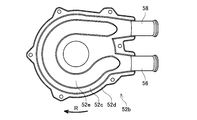
- FIG. 2 is a perspective view of the purge pump 10 as viewed from the pump unit 50 side.
- FIG. 3 is a cross-sectional view showing a III-III cross section of FIG.
- “upper” and “lower” are expressed with reference to the vertical direction in FIG. 3, but the vertical direction in FIG. 3 is not necessarily the direction in which the purge pump 10 is mounted on the automobile.
- the purge pump 10 includes a motor unit 20 and a pump unit 50.
- the motor unit 20 has a brushless motor.
- the motor unit 20 includes an upper housing 26, a rotor (not shown), a stator 22, and a control circuit 24.
- the upper housing 26 accommodates the rotor, the stator 22, and the control circuit 24.
- the control circuit 24 converts the DC power supplied from the vehicle battery into U-phase, V-phase, and W-phase three-phase AC power, and supplies it to the stator 22.
- the control circuit 24 supplies power to the stator 22 in accordance with a signal supplied from the ECU 6.
- the stator 22 has a cylindrical shape, and a rotor is disposed at the center thereof.
- the rotor is disposed so as to be rotatable with respect to the stator 22.
- the rotor has permanent magnets that are magnetized in different directions alternately in the circumferential direction.
- the rotor rotates around the central axis X of the shaft 30 (hereinafter referred to as “rotary axis X”) when electric power is supplied to the stator 22.
- a pump unit 50 is disposed below the motor unit 20.
- the pump unit 50 is driven by the motor unit 20.
- the pump unit 50 includes a lower housing 52 and an impeller 54.
- the lower housing 52 is fixed to the lower end of the upper housing 26.
- the lower housing 52 includes a bottom wall 52a and a cover 52b.
- the cover 52b includes an upper wall 52c, a peripheral wall 52d, a suction port 56, and a discharge port 58 (see FIG. 2).
- the upper wall 52 c is disposed at the lower end of the upper housing 26.
- the peripheral wall 52d protrudes downward from the upper wall 52c and goes around the outer peripheral edge of the upper wall 52c.
- a bottom wall 52a is disposed at the lower end of the peripheral wall 52d.
- the bottom wall 52a is fixed to the cover 52b with bolts.
- the bottom wall 52a closes the lower end of the peripheral wall 52d.
- a space 60 is defined by the bottom wall 52a and the cover 52b.
- FIG. 5 is a view of the cover 52b as viewed from below.
- a suction port 56 and a discharge port 58 that respectively communicate with the space 60 protrude outward from the peripheral wall 52d.
- the suction port 56 and the discharge port 58 are arranged in parallel to each other and perpendicular to the vertical direction.
- the suction port 56 communicates with the canister 73 via a communication pipe 74.
- the suction port 56 includes a suction flow path inside, and introduces vaporized fuel from the canister 73 into the space 60.
- the discharge port 58 has a discharge flow path therein and communicates with the suction port 56 in the lower housing 52, and discharges vaporized fuel sucked into the space 60 out of the purge pump 10.
- the upper wall 52c has a facing groove 52e extending from the suction port 56 to the discharge port 58 along the peripheral wall 52d.
- the bottom wall 52a has an opposing groove 52f (see FIG. 3) extending from the suction port 56 to the discharge port 58 along the peripheral wall 52d.
- the opposing groove 52e and the opposing groove 52f have a certain depth at an intermediate position excluding both ends in the longitudinal direction, specifically, at a position facing the impeller 54.
- the suction port 56 and the discharge are respectively provided at both ends in the longitudinal direction. It gradually becomes shallower as the port 58 is approached.
- the discharge port 58 and the suction port 56 are isolated by the peripheral wall 52d. Thereby, it is possible to suppress the gas from flowing from the high pressure discharge port 58 to the low pressure suction port 56.
- an impeller 54 is accommodated in the space 60.
- the impeller 54 has a disk shape.
- the thickness of the impeller 54 is slightly smaller than the gap between the upper wall 52c and the bottom wall 52a of the lower housing 52.
- the impeller 54 is opposed to the upper wall 52c and the bottom wall 52a with a small gap.
- a small gap is provided between the impeller 54 and the peripheral wall 52d.
- the impeller 54 has a fitting hole fitted into the shaft 30 at the center. Thereby, the impeller 54 rotates around the rotation axis X as the shaft 30 rotates.
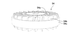
- the impeller 54 has a blade groove region 54f having a plurality of blades 54a and a plurality of blade grooves 54b on the outer peripheral portion of the upper surface 54g.
- the impeller 54 has a blade groove region 54f having a plurality of blades 54a and a plurality of blade grooves 54b on the outer peripheral portion of the lower surface 54h.
- the upper surface 54g and the lower surface 54h can be referred to as end surfaces of the impeller 54 in the rotation axis X direction.
- the blade groove region 54f disposed on the upper surface 54g is disposed to face the facing groove 52e.
- the blade groove region 54f disposed on the lower surface 54h is disposed to face the facing groove 52f.
- Each blade groove region 54 f makes a round in the circumferential direction of the impeller 54 inside the outer peripheral wall 54 c of the impeller 54.
- the plurality of blades 54a have the same shape.
- the plurality of blades 54a are arranged at equal intervals in the circumferential direction of the impeller 54 in the blade groove region 54f.
- One blade groove 54 b is disposed between two blades 54 a adjacent to each other in the circumferential direction of the impeller 54. That is, the plurality of blade grooves 54 b are arranged at equal intervals in the circumferential direction of the impeller 54 inside the outer peripheral wall 54 c of the impeller 54. In other words, the outer ends of the plurality of blade grooves 54b are closed by the outer peripheral wall 54c.
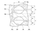
- FIG. 6 is an enlarged view of the area AR of FIG. 3, a position that passes through the rotation axis X (that is, includes the rotation axis X) and has the deepest depth of the blade grooves 54 b disposed on both surfaces of the impeller 54.
- the cross section of is represented.
- each of the plurality of blade grooves 54 b arranged on the lower surface 54 h of the impeller 54 opens on the lower surface 54 h side of the impeller 54, and is closed on the upper surface 54 g side of the impeller 54.
- each of the plurality of blade grooves 54b disposed on the upper surface 54g of the impeller 54 opens on the upper surface 54g side of the impeller 54, and closes on the lower surface 54h side of the impeller 54. That is, the plurality of blade grooves 54b disposed on the lower surface 54h of the impeller 54 and the plurality of blade grooves 54b disposed on the upper surface 54g of the impeller 54 are blocked and do not communicate with each other.
- the impeller 54 While the purge pump 10 is being driven, the impeller 54 is rotated along with the rotor of the motor unit 20. As a result, the gas containing vaporized fuel adsorbed by the canister 73 is sucked into the lower housing 52 from the suction port 56. In the space 57 formed by the blade groove 54b and the opposing groove 52e, a gas vortex (swirl) is generated. The same applies to the space 59 formed by the blade groove 54b and the opposing groove 52f. As a result, the gas in the lower housing 52 is pressurized and discharged from the discharge port 58.
- the discharge flow rate was calculated. It can be said that the pump efficiency is high when the discharge flow rate is relatively large while the input energy to the pump unit 50 is constant, and the pump efficiency is low when the discharge flow rate is relatively small.
- a value approximately 1/6 of the diameter of the impeller 54 was adopted.
- the flow path height H is equal to the length of the gap between the blade groove depth D1 + the opposed groove depth D2 + the impeller 54 and the upper wall 52c (or the bottom wall 52a).
- the flow path width W is equal to the width of the blade groove 54b and the widths of the opposing grooves 52e and 52f.
- FIG. 7 is a graph showing the relationship between D2 / D1 and the discharge flow rate.
- the horizontal axis indicates D2 / D1, and the vertical axis indicates the discharge flow rate (liter / minute).
- FIG. 8 is a graph showing the relationship between W / H and discharge flow rate. The horizontal axis indicates W / H, and the vertical axis indicates the discharge flow rate (liter / minute).
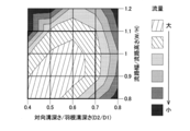
- FIG. 9 is a map showing the relationship among D2 / D1, W / H, and discharge flow rate. As is apparent from the graphs of FIGS. 7 and 8, the ratio D2 / D1 of the opposed groove depth D2 to the blade groove depth D1 in any case of the ratio W / H of the flow path width W to the flow path height H.
- 10 to 12 show a vortex flow in a cross section passing through the rotation axis X of the impeller 54 and the deepest point of the blade groove 54b. 10 to 12, the left side is the center side of the impeller 54, and the right side is the outer peripheral side of the impeller 54. Further, in FIGS. 10 to 12, arrows along the vortex flow are drawn for easy understanding of the vortex flow.
- the pump efficiency can be improved. This is because, when viewed in a cross section orthogonal to the rotation direction R of the impeller 54 (that is, the cross section of FIGS. 10 to 12, hereinafter simply referred to as “orthogonal cross section”), the vicinity of the center of the vortex is the outer peripheral edge of the vortex. The gas pressure is lower than the vicinity. As a result, when viewed in an orthogonal cross section, a flow is generated from the high pressure side to the low pressure side, that is, the gas from the vicinity of the outer peripheral end of the vortex to the vicinity of the center. The pressure of the gas in the spaces 57 and 59 increases as the impeller 54 rotates.
- the impeller 54 since the impeller 54 has the outer peripheral wall 54c, the gas flow toward the outer peripheral direction of the impeller 54 can be guided in the spaces 57 and 59, and the gas can be smoothly swirled.
- the shape of the outer peripheral wall 54c of the impeller 54 is not limited to the shape of the embodiment.
- the outer peripheral wall 54 c is disposed at the center in the vertical direction of the impeller 54, but may not be disposed at the upper and lower ends.
- the upper end of the outer peripheral wall 54c may be located at the same position as or above the center of the vortex in the vertical direction.
- the lower end of the outer peripheral wall 54c may be located at the same position as or below the center of the vortex in the vertical direction.
- the impeller 54 may not have the outer peripheral wall 54c.
- the blades 54a and the blade grooves 54b of the impeller 54 have the same shape on the upper and lower surfaces 54g and 54h.
- the shapes of the blades 54a and the blade grooves 54b may be different on the upper and lower surfaces 54g and 54h.
- the blades 54a and the blade grooves 54b may be disposed only on one of the upper and lower surfaces 54g and 54h.
- the suction port 56 and the discharge port 58 of the pump unit 50 extend in a direction perpendicular to the rotation axis X of the impeller 54.
- the suction port 56 and the discharge port 58 of the pump unit 50 may extend parallel to the rotation axis X.
- the “vortex pump” in this specification is not limited to the purge pump 10 and can be used for other systems.
- a pump for supplying exhaust gas to the intake pipe 80 in exhaust gas recirculation that is, EGR (abbreviation of Exhaust Gas ⁇ ⁇ Recirculation)
- EGR abbreviation of Exhaust Gas ⁇ ⁇ Recirculation
Landscapes
- Engineering & Computer Science (AREA)
- Mechanical Engineering (AREA)
- General Engineering & Computer Science (AREA)
- Structures Of Non-Positive Displacement Pumps (AREA)
Abstract
気体を圧送する渦流ポンプであって、吸入流路と吐出流路とを有するハウジングと、 ハウジングに収容されており、回転軸回りに回転するインペラと、を備え、インペラは、回転軸方向の両面の少なくとも一方の端面の外周部に、回転方向に沿って、複数の羽根と隣り合う羽根の間にそれぞれ配置される複数の羽根溝とを有する羽根溝領域を有し、複数の羽根溝のそれぞれは、一方の端面側に開口する一方、他方の端面側に閉塞しており、ハウジングは、羽根溝領域に対向しており、インペラの回転方向に延びる対向溝を有し、対向溝のインペラ回転方向の両端を除く中間位置において、各羽根溝の最も深い位置での羽根溝の深さに対する対向溝の深さが0.7以下である、渦流ポンプ。
Description
本明細書は、気体を圧送する渦流ポンプに関する。なお、渦流ポンプは、ウエスコポンプ、カスケードポンプ、再生ポンプとも呼ばれる。
実開平5-73287号公報に、加圧された燃料を自動車用の燃料噴射装置に供給する渦流ポンプが開示されている。渦流ポンプは、外周部に複数の羽根を有するインペラと、インペラを収容するハウジングと、を有する。ハウジングとインペラによって、インペラの羽根の周囲に流体通路が形成されている。
渦流ポンプでは、インペラの回転によって、流体通路内の流体に、インペラの回転方向に沿った中心軸回りの渦流(旋回流とも呼ばれる)を発生させることによって、流体を昇圧し、吐出する。本明細書では、気体を圧送する渦流ポンプにおいて、ポンプ効率を向上させる技術を提供する。
本明細書は、気体を圧送する渦流ポンプを開示する。渦流ポンプは、吸入流路と吐出流路とを有するハウジングと、ハウジングに収容されており、回転軸回りに回転するインペラと、を備えていてもよい。インペラは、回転軸方向の両面の少なくとも一方の端面のそれぞれの外周部に、回転方向に沿って、複数の羽根と隣り合う羽根の間にそれぞれ配置される複数の羽根溝とを有する羽根溝領域を有していてもよい。複数の羽根溝のそれぞれは、一方の端面側に開口する一方、他方の端面側に閉塞していてもよい。ハウジングは、羽根溝領域に対向しており、インペラの回転方向に延びる対向溝を有していてもよい。対向溝のインペラ回転方向の両端を除く中間位置において、各羽根溝の最も深い位置での羽根溝の深さに対する対向溝の深さが0.7以下であってもよい。
発明者らは、対向溝のインペラ回転方向の両端を除く中間位置において、各羽根溝の最も深い位置での羽根溝の深さに対する対向溝の深さが0.7以下である場合に、渦流ポンプのポンプ効率が良くなることを見出した。上記の構成によれば、気体用の渦流ポンプにおいて、ポンプ効率を向上させることができる。
本明細書は、気体を圧送する別の渦流ポンプを開示する。渦流ポンプは、吸入流路と吐出流路とを有するハウジングと、ハウジングに収容されており、回転軸回りに回転するインペラと、を備えていてもよい。インペラは、回転軸方向の両面の少なくとも一方の端面の外周部に、回転方向に沿って、複数の羽根と隣り合う羽根の間にそれぞれ配置される複数の羽根溝とを有する羽根溝領域を有していてもよい。複数の羽根溝のそれぞれは、一方の端面側に開口する一方、他方の端面側に閉塞していてもよい。ハウジングは、羽根溝領域に対向しており、インペラの回転方向に延びる対向溝を有していてもよい。対向溝のインペラ回転方向の両端を除く中間位置において、各羽根溝の最も深い位置での羽根溝の深さに対する対向溝の深さの割合が、インペラの回転中に各羽根溝と対向溝とによって発生する渦流の中心が羽根溝内に位置するように設定されていてもよい。
渦流ポンプでは、インペラの回転によって、インペラの羽根溝とハウジングの対向溝とによって形成される空間に、インペラの回転方向に沿った中心軸回りの渦流が発生する。発明者らは、渦流の中心が羽根溝内に位置することによって、ポンプ効率を向上させることができることを見出した。ポンプ効率が向上される理由として、インペラの回転方向に直交する断面(以下では単に「直交断面」と呼ぶ)で見たときに、渦流の中心近傍は、渦流の外周端近傍と比較して気体の圧力が低い。この結果、直交断面で見たときに、気体に、高圧側から低圧側、即ち、渦流の外周端近傍から中心近傍に向かう流れが発生する。
インペラの羽根溝とハウジングの対向溝とによって形成される空間内の気体の圧力は、インペラの回転に伴って上昇する。即ち、インペラの羽根溝とハウジングの対向溝とによって形成される空間内の気体の圧力は、インペラの回転方向に進むのに従って上昇する。このため、仮に、渦流の中心が羽根溝よりも外側に位置すると、中心近傍の気体は、より低圧側、即ち、インペラの回転方向とは反対向きに逆流する。この結果、渦流の中心が羽根溝よりも外側に位置すると、ポンプ効率が低下する。一方、渦流の中心が羽根溝内に位置すれば、中心近傍の気体は、羽根溝のインペラの回転方向と反対側に位置する羽根によって、逆流することが防止される。これにより、気体の逆流を抑制し、ポンプ効率を向上することができる。
本発明者は、上記観点から、渦流ポンプの構造を検討し、羽根溝の深さに対する対向溝の深さを変化させることによって、渦流の中心位置が変動することを見出した。さらなる鋭意検討の結果、羽根溝の深さに対する対向溝の深さを0.7以下に設定すると、渦流の中心がおおむね羽根溝内に収まり、0.7より大きい場合と比較して、流体の吐出流量が多くなることを見出した。
インペラの回転軸と各羽根溝の最も深い位置を通過する断面で見たときに、羽根溝の底端から対向溝の底端までの距離に対する羽根溝の幅が0.8以上1.0以下であってもよい。この構成によれば、直交断面の渦流の形状を、円形に近づけることができる。この結果、上記の数値範囲であれば、渦流をスムーズに流すことができ、ポンプ効率を向上させることができる。
インペラの回転軸と各羽根溝の最も深い位置を通過する断面で見たときに、羽根溝の深さに対する対向溝の深さが0.4以上0.7以下であり、かつ、羽根溝の底端から対向溝の底端までの距離に対する羽根溝の幅が0.8以上1.1以下であってもよい。この構成によれば、直交断面の渦流の形状を、円形に近づけることができる。この結果、上記の数値範囲であれば、渦流をスムーズに流すことができ、ポンプ効率を向上させることができる。
インペラは、外周縁に複数の羽根溝のインペラ外周側を閉塞する外周壁を有していてもよい。この構成によれば、外周壁によって、インペラの外周方向に向かって流れる気体を渦流の旋回方向に案内することができる。
図面を参照して、実施例のパージポンプ10を説明する。図1に示すように、パージポンプ10は、自動車に搭載され、燃料タンク3に貯留される燃料をエンジン8に供給する燃料供給システム1に配置される。燃料供給システム1は、燃料タンク3からエンジン8に燃料を供給するためのメイン供給経路2とパージ供給経路4を有する。
メイン供給経路2には、燃料ポンプユニット7と、供給管70と、インジェクタ5と、が配置されている。燃料ポンプユニット7は、燃料ポンプ、プレッシャレギュレータ、制御回路等を備える。燃料ポンプユニット7では、後述するECU(Engine Control Unitの略)6から供給される信号に応じて制御回路が燃料ポンプを制御する。燃料ポンプは、燃料タンク3内の燃料を昇圧して吐出する。燃料ポンプから吐出される燃料は、プレッシャレギュレータで調圧されて、燃料ポンプユニット7から供給管70に供給される。
供給管70は、燃料ポンプユニット7とインジェクタ5とを連通する。供給管70に供給された燃料は、供給管70内をインジェクタ5まで流れる。インジェクタ5は、ECU6によって開度がコントロールされる弁を有する。インジェクタ5は、弁が開かれると、供給管70から供給される燃料をエンジン8に供給する。
パージ供給経路4には、キャニスタ73と、パージポンプ10と、VSV(Vacuum Switching Valveの略)100と、それらを連通する連通管72,74,76,78と、を備える。キャニスタ73は、燃料タンク3内で発生した気化燃料を吸着する。キャニスタ73は、タンクポートと、パージポートと、大気ポートとを備える。図1にパージ供給経路4から吸気管80までの気体の流れ方向が矢印で示されている。タンクポートは、燃料タンク3の上端から延びる連通管72に接続されている。これにより、キャニスタ73は、燃料タンク3の上端から延びる連通管72に連通する。キャニスタ73は、燃料を吸着可能な活性炭を収容する。活性炭は、燃料タンク3から連通管72を介してキャニスタ73内部に流入する気体から気化燃料を吸着する。キャニスタ73内部に流入した気体は、気化燃料が吸着された後、キャニスタ73の大気ポートを通過して大気に放出される。これにより、気化燃料が大気に放出されることを防止することができる。
キャニスタ73のパージポートには、連通管74を介して、パージポンプ10が接続されている。詳細な構造は後述するが、パージポンプ10は、気体を圧送する、いわゆる渦流ポンプである。パージポンプ10は、ECU6によって制御される。パージポンプ10は、キャニスタ73で吸着されている気化燃料を吸入し、昇圧して吐出する。パージポンプ10が駆動している間、キャニスタ73では、大気ポートから大気が吸入され、吸着された気化燃料とともにパージポンプ10に流入される。
パージポンプ10から吐出された気化燃料は、連通管76とVSV100と連通管78とを通過して吸気管80に流入する。VSV100は、ECU6に制御される電磁弁である。ECU6は、VSV100を制御することによって、パージ供給経路4から吸気管80に供給される気化燃料量を調整する。VSV100は、インジェクタ5よりも上流側で吸気管80に接続される。吸気管80は、エンジン8に空気を供給する配管である。吸気管80のVSV100が接続される位置よりも上流側には、スロットルバルブ82が配置されている。スロットルバルブ82は、吸気管80の開度を制御することによって、エンジン8に流入する空気を調整する。スロットルバルブ82は、ECU6によって制御される。
吸気管80のスロットルバルブ82よりも上流側には、エアクリーナ84が配置されている。エアクリーナ84は、吸気管80に流入する空気から異物を除去するフィルタを有する。吸気管80では、スロットルバルブ82が開くと、エアクリーナ84からエンジン8に向けて吸気される。エンジン8は、吸気管80からの空気と燃料とを内部で燃焼し、燃焼後に排気する。
パージ供給経路4では、パージポンプ10が駆動することによって、キャニスタ73に吸着された気化燃料を吸気管80に供給することができる。エンジン8が駆動している場合、吸気管80内に負圧が発生している。このため、パージポンプ10が停止されている状態でも、キャニスタ73に吸着された気化燃料が、吸気管80内の負圧によって停止中のパージポンプ10内を通過して吸気管80内に吸入される。一方で、自動車の停止時にエンジン8のアイドリングを停止したり、ハイブリッド車のようにエンジン8を停止してモータで走行する場合、言い換えると、環境対策のためにエンジン8の駆動を制御する場合、エンジン8の駆動による吸気管80内の負圧が発生しない状況が生じる。パージポンプ10は、このような状況において、エンジン8に替わってキャニスタ73に吸着された気化燃料を吸気管80に供給することができる。なお、変形例では、エンジン8が駆動しており、吸気管80内に負圧が発生している状況でも、パージポンプ10が駆動し、気化燃料を吸入し吐出してもよい。
次いで、パージポンプ10の構成を説明する。図2は、パージポンプ10のポンプ部50側から見た斜視図を示す。図3は、図2のIII-III断面を示す断面図である。以下では、図3の上下方向を基準として「上」、「下」を表すが、図3の上下方向が、パージポンプ10が自動車に搭載される方向とは限らない。
パージポンプ10は、モータ部20と、ポンプ部50と、を備える。モータ部20は、ブラシレスモータを有する。モータ部20は、上方ハウジング26と、ロータ(図示省略)と、ステータ22と、制御回路24と、を備える。上方ハウジング26は、ロータと、ステータ22と、制御回路24とを収容する。制御回路24は、自動車のバッテリから供給される直流電力をU相、V相、W相の三相交流電力に変換し、ステータ22に供給する。制御回路24は、ECU6から供給される信号に従ってステータ22に電力を供給する。ステータ22は、円筒形状を有しており、その中心部には、ロータが配置されている。ロータは、ステータ22に対して回転可能に配置されている。ロータは、その周方向に交互に異なる方向に磁化されている永久磁石を有する。ロータは、ステータ22に電力が供給されることによって、シャフト30の中心軸X(以下では「回転軸X」と呼ぶ)を中心に回転する。
モータ部20の下方には、ポンプ部50が配置されている。ポンプ部50は、モータ部20によって駆動される。ポンプ部50は、下方ハウジング52と、インペラ54と、を備える。下方ハウジング52は、上方ハウジング26の下端に固定されている。下方ハウジング52は、底壁52aとカバー52bとを備える。カバー52bは、上壁52cと、周壁52dと、吸入ポート56と、吐出ポート58(図2参照)と、を備える。上壁52cは、上方ハウジング26の下端に配置されている。周壁52dは、上壁52cから下方に向かって突出しており、上壁52cの外周縁を一巡する。周壁52dの下端には、底壁52aが配置されている。底壁52aは、ボルトによってカバー52bに固定されている。底壁52aは、周壁52dの下端を閉塞している。底壁52aとカバー52bとによって、空間60が画定されている。
図5は、カバー52bを下方から見た図である。周壁52dには、それぞれが空間60に連通する吸入ポート56と吐出ポート58とが外側に向かって突出している。吸入ポート56と吐出ポート58とは、互いに平行に、かつ、上下方向と垂直に配置されている。吸入ポート56は、連通管74を介してキャニスタ73に連通している。吸入ポート56は、内部に吸入流路を備え、キャニスタ73から気化燃料を空間60に導入する。吐出ポート58は、内部に吐出流路を備え、下方ハウジング52内で吸入ポート56に連通しており、空間60内に吸入された気化燃料を、パージポンプ10外に排出する。
上壁52cには、吸入ポート56から吐出ポート58まで周壁52dに沿って延びる対向溝52eを有する。底壁52aも同様に、吸入ポート56から吐出ポート58まで周壁52dに沿って延びる対向溝52f(図3参照)を有する。対向溝52e及び対向溝52fは、長手方向の両端を除く中間位置、詳細には、インペラ54に対向する位置において、一定の深さを有し、長手方向の両端では、それぞれ吸入ポート56、吐出ポート58に近づくのに従って徐々に浅くなっている。インペラ54の回転方向Rに沿って見たときに、吐出ポート58と吸入ポート56との間は、周壁52dによって、隔離されている。これにより、高圧の吐出ポート58から低圧の吸入ポート56に気体が流れることを抑制することができる。
図3に示すように、空間60には、インペラ54が収容されている。インペラ54は、円板形状を有する。インペラ54の厚みは、下方ハウジング52の上壁52cと底壁52aとの隙間よりも若干小さい。インペラ54は、上壁52cと底壁52aのそれぞれに対して、小さな隙間を有して対向している。また、インペラ54と周壁52dとの間には、小さな隙間が設けられている。インペラ54は、中心にシャフト30に嵌合される嵌合孔を有する。これにより、インペラ54は、シャフト30の回転に伴って、回転軸Xを中心に回転する。
図4に示されるように、インペラ54は、上面54gの外周部に、複数の羽根54aと複数の羽根溝54bとを有する羽根溝領域54fを有する。なお、図面では、1個の羽根54aと1個の羽根溝54bのみに符号が付されている。同様に、インペラ54は、下面54hの外周部にも、複数の羽根54aと複数の羽根溝54bとを有する羽根溝領域54fを有する。なお、上面54g及び下面54hを、インペラ54の回転軸X方向の端面ということができる。上面54gに配置される羽根溝領域54fは、対向溝52eに対向して配置されている。同様に、下面54hに配置される羽根溝領域54fは、対向溝52fに対向して配置されている。各羽根溝領域54fは、インペラ54の外周壁54cの内側において、インペラ54の周方向に一巡する。複数の羽根54aは、同一の形状を有する。複数の羽根54aは、羽根溝領域54fにおいて、インペラ54の周方向に等間隔で配置されている。インペラ54の周方向に隣り合う2個の羽根54aの間には、1個の羽根溝54bが配置されている。即ち、複数の羽根溝54bは、インペラ54の外周壁54cの内側において、インペラ54の周方向に等間隔で配置されている。言い換えると、複数の羽根溝54bは、外周壁54cによって、外周側の端部が閉塞されている。
図6は、図3の領域ARの拡大図であり、回転軸Xを通過し(即ち回転軸Xを含み)、かつ、インペラ54の両面に配置される羽根溝54bの深さが最も深い位置の断面を表す。図6に示すように、インペラ54の下面54hに配置されている複数の羽根溝54bのそれぞれは、インペラ54の下面54h側に開口する一方、インペラ54の上面54g側で閉塞している。同様に、インペラ54の上面54gに配置されている複数の羽根溝54bのそれぞれは、インペラ54の上面54g側で開口する一方、インペラ54の下面54h側で閉塞している。即ち、インペラ54の下面54hに配置されている複数の羽根溝54bとインペラ54の上面54gに配置されている複数の羽根溝54bとは遮断されており、連通していない。
パージポンプ10の駆動中では、モータ部20のロータに伴って、インペラ54が回転される。この結果、キャニスタ73に吸着された気化燃料を含む気体が吸入ポート56から下方ハウジング52内に吸入される。羽根溝54bと対向溝52eとによって形成される空間57内では気体の渦流(旋回流)が発生する。羽根溝54bと対向溝52fとによって形成される空間59内でも同様である。この結果、下方ハウジング52内の気体が昇圧され、吐出ポート58から吐出される。
次いで、図7から図9を参照して、パージポンプ10を用いて行われたシミュレーション結果を示す。本シミュレーションでは、パージポンプ10のポンプ部50をモデル化し、インペラ54を回転させたときの吐出ポート58から吐出される気体の流量を算出した。なお、インペラ54の回転数を一定とし、ポンプ部50に入力されるエネルギーを略一定とした。
本シミュレーションでは、図6に示される羽根溝深さD1に対する対向溝深さD2の割合D2/D1と、流路高さHに対する流路幅Wの割合W/Hと、を変化させた場合の吐出流量を算出した。ポンプ部50への入力エネルギーが一定である状況で吐出流量が比較的に大きい場合はポンプ効率が高く、吐出流量が比較的に小さい場合はポンプ効率が低いと言うことができる。なお、羽根溝深さD1は、インペラ54の直径のおよそ1/6の値を採用した。なお、流路高さHは、羽根溝深さD1+対向溝深さD2+インペラ54と上壁52c(又は底壁52a)との隙間の長さに等しい。また、流路幅Wは、羽根溝54bの幅及び、対向溝52e、52fの幅に等しい。
図7は、D2/D1と吐出流量との関係を示すグラフである。横軸はD2/D1を示し、縦軸は吐出流量(リットル/分)を示す。図8は、W/Hと吐出流量との関係を示すグラフである。横軸はW/Hを示し、縦軸は吐出流量(リットル/分)を示す。図9は、D2/D1とW/Hと吐出流量との関係を示すマップである。図7及び図8のグラフから明らかなように、流路高さHに対する流路幅Wの割合W/Hがいずれの場合も、羽根溝深さD1に対する対向溝深さD2の割合D2/D1が0.7以下のある値で、吐出流量が最も多くなる。即ち、D2/D1が0.7以下のある値で、ポンプ効率が最も良くなる。そして、吐出流量が最も多くなるD2/D1の値からD2/D1=0.7まで間では、吐出流量が最も多い場合の3/4以上の流量を維持することができ、比較的にポンプ効率が良いと言える。特に、流路高さHに対する流路幅Wの割合W/Hが、0.8以上であり、1.0以下である場合、特にポンプ効率が良いということができる。
なお、シミュレーション結果では、D2/D1が0.6である場合には、W/Hが0.7以上1.2以下の範囲で、吐出流量が大きく低下する事態は見受けられず、ポンプ効率を高く維持することができる。特に、0.4≦D2/D1≦0.7であり、0.8≦W/H≦1.1では、ポンプ効率を高くすることができる。
次いで、ポンプ効率を向上させることができる理由を説明する。パージポンプ10では、インペラ54の回転によって、羽根溝54bと対向溝52e,52fとによって形成される空間57,59に、インペラ54の回転方向Rに沿った中心軸回りの渦流が発生する。図10は、D2/D1=0.6であり、W/H=1.0である場合の羽根溝54bと対向溝52eとの空間57に発生する気体の流れ(即ち渦流の様子)を表すシミュレーション結果である。図11は、D2/D1=0.8であり、W/H=1.0である場合の空間57に発生する気体の流れを表すシミュレーション結果である。図12は、D2/D1=0.8であり、W/H=0.8である場合の空間57に発生する気体の流れを表すシミュレーション結果である。なお、図10~図12では、インペラ54の回転軸Xと羽根溝54bの最も深い地点とを通過する断面における渦流を示す。図10~図12では、向かって左側がインペラ54の中心側であり、右側がインペラ54の外周側である。また、図10~図12には、渦流の流れを分かりやすくするために、渦流の流れに沿った矢印が描かれている。
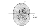
図10に示すように、D2/D1=0.6でありW/H=1.0の場合では、渦流の中心C1が羽根溝54b内に位置している。一方で、図11に示すように、D2/D1=0.8であり、W/H=1.0の場合では、渦流の中心C2が羽根溝54b外に位置している。図12でも同様に、D2/D1=0.8であり、W/H=0.8の場合では、渦流の中心C3が羽根溝54b外に位置している。
渦流の中心が羽根溝54b内に位置する場合、ポンプ効率を向上させることができる。これは、インペラ54の回転方向Rに直交する断面(即ち、図10~図12の断面、以下では単に「直交断面」と呼ぶ)で見たときに、渦流の中心近傍は、渦流の外周端近傍と比較して気体の圧力が低い。この結果、直交断面で見たときに、高圧側から低圧側、即ち、気体が渦流の外周端近傍から中心近傍に向かう流れが発生する。空間57,59内の気体の圧力は、インペラ54の回転に伴って上昇する。このため、空間57,59内の気体は、回転方向Rに進むのに従って上昇する。この結果、渦流の中心近傍の気体は、より低圧側、即ち、インペラ54の回転方向Rと反対側に向かって流れようとする。
図13は、D2/D1=0.6でありW/H=1.0である場合、即ち、渦流の中心C1が羽根溝54b内に位置する場合の中心C1付近の気体の流れの向きと流速とを上方から見た図である。図14は、D2/D1=0.8であり、W/H=0.8である場合、即ち、渦流の中心C3が羽根溝54b外に位置する場合の中心C3付近の気体の流れの向きと流速とを上方から見た図である。なお、図13及び図14には、羽根溝54bの回転方向Rの反対側に位置する羽根54aが示されている。曲線が羽根54aよりも回転方向R側に位置する場合は気体が回転方向Rに沿って流れることを表し、曲線が羽根54aよりも回転方向Rと反対側に位置する場合は気体が回転方向Rに対して逆流していることを表し、羽根54aから距離によって流速の大きさが表されている。図14に示すように、渦流の中心C3が羽根溝54b外に位置する場合には、中心C3は、下流側の羽根54aの上方に位置する。このため、中心C3に流れてきた気体は、より低圧側、即ち、回転方向Rと反対側に向かって逆流する。これにより、ポンプ効率が低下する。
一方、図13に示すように、渦流の中心C1が羽根溝54b内に位置する場合には、中心X1の反対側には、羽根54aが位置している。このため、中心C1に流れてきた気体は、羽根溝54bによって回転方向Rと反対側に向かって逆流することが防止されている。これにより、ポンプ効率を向上することができる。言い換えると、対向溝52e,52fの回転方向Rの両端を除く中間位置において、各羽根溝52bの最も深い位置での羽根溝54bの深さに対する対向溝52e,52fの深さの割合が、インペラ54の回転中に各羽根溝54bと対向溝52e,52fとによって発生する渦流の中心が羽根溝54b内に位置するように設定されていることによって、ポンプ効率を向上することができる。
また、インペラ54が外周壁54cを有するために、空間57,59内でインペラ54の外周方向に向かう気体の流れを案内し、気体をスムーズに旋回させることができる。
以上、本発明の実施形態について詳細に説明したが、これらは例示に過ぎず、特許請求の範囲を限定するものではない。特許請求の範囲に記載の技術には、以上に例示した具体例を様々に変形、変更したものが含まれる。
例えば、インペラ54の外周壁54cの形状は、実施例の形状に限られない。例えば、図15に示すように、外周壁54cは、インペラ54の上下方向の中央部に配置される一方、上下端部に配置されていなくてもよい。この場合、外周壁54cの上端は、上下方向において、渦流の中心と同じ位置かそれより上方に位置していてもよい。外周壁54cの下端も同様に、上下方向において、渦流の中心と同じ位置かそれより下方に位置していてもよい。あるいは、インペラ54は、外周壁54cを有していなくてもよい。
また、上記の実施例では、インペラ54の羽根54a及び羽根溝54bは、上下面54g,54hで同一の形状を有している。しかしながら、羽根54a及び羽根溝54bの形状は、上下面54g,54hで異なっていてもよい。あるいは、羽根54a及び羽根溝54bは、上下面54g,54hのいずれか一方の面にのみ配置されていてもよい。
また、上記の実施例では、ポンプ部50の吸入ポート56及び吐出ポート58は、インペラ54の回転軸Xに垂直な方向に延びている。しかしながら、ポンプ部50の吸入ポート56及び吐出ポート58は、回転軸Xに平行に延びていてもよい。
本明細書の「渦流ポンプ」は、パージポンプ10に限られず、他のシステムにも利用することができる。例えば、エンジン8の排気を循環させ、吸気と混合させてエンジン8の燃料室に供給する排気再循環(即ちEGR(Exhaust Gas Recirculationの略))において、排気を吸気管80に供給するためのポンプとして利用することができる。また、自動車以外の産業用のポンプとしても利用することができる。
また、本明細書または図面に説明した技術要素は、単独であるいは各種の組合せによって技術的有用性を発揮するものであり、出願時請求項記載の組合せに限定されるものではない。また、本明細書または図面に例示した技術は複数目的を同時に達成するものであり、そのうちの一つの目的を達成すること自体で技術的有用性を持つものである。
Claims (5)
- 気体を圧送する渦流ポンプであって、
吸入流路と吐出流路とを有するハウジングと、
ハウジングに収容されており、回転軸回りに回転するインペラと、を備え、
インペラは、回転軸方向の両面の少なくとも一方の端面の外周部に、回転方向に沿って、複数の羽根と隣り合う羽根の間にそれぞれ配置される複数の羽根溝とを有する羽根溝領域を有し、
複数の羽根溝のそれぞれは、一方の端面側に開口する一方、他方の端面側に閉塞しており、
ハウジングは、羽根溝領域に対向しており、インペラの回転方向に延びる対向溝を有し、
対向溝のインペラ回転方向の両端を除く中間位置において、各羽根溝の最も深い位置での羽根溝の深さに対する対向溝の深さが0.7以下である、渦流ポンプ。 - インペラの回転軸と各羽根溝の最も深い位置を通過する断面で見たときに、羽根溝の底端から対向溝の底端までの距離に対する羽根溝の幅が0.8以上1.0以下である、請求項1に記載の渦流ポンプ。
- インペラの回転軸と各羽根溝の最も深い位置を通過する断面で見たときに、羽根溝の深さに対する対向溝の深さが0.4以上0.7以下であり、かつ、羽根溝の底端から対向溝の底端までの距離に対する羽根溝の幅が0.8以上1.1以下である、請求項1に記載の渦流ポンプ。
- 気体を圧送する渦流ポンプであって、
吸入流路と吐出流路とを有するハウジングと、
ハウジングに収容されており、回転軸回りに回転するインペラと、を備え、
インペラは、回転軸方向の両面の少なくとも一方の端面の外周部に、回転方向に沿って、複数の羽根と隣り合う羽根の間にそれぞれ配置される複数の羽根溝とを有する羽根溝領域を有し、
複数の羽根溝のそれぞれは、一方の端面側に開口する一方、他方の端面側に閉塞しており、
ハウジングは、羽根溝領域に対向しており、インペラの回転方向に延びる対向溝を有し、
対向溝のインペラ回転方向の両端を除く中間位置において、各羽根溝の最も深い位置での羽根溝の深さに対する対向溝の深さの割合が、インペラの回転中に各羽根溝と対向溝とによって発生する渦流の中心が羽根溝内に位置するように設定されている、渦流ポンプ。 - インペラは、外周縁に複数の羽根溝のインペラ外周側を閉塞する外周壁を有する、請求項1から4のいずれか一項に記載の渦流ポンプ。
Priority Applications (2)
| Application Number | Priority Date | Filing Date | Title |
|---|---|---|---|
| CN201680057098.1A CN108138788B (zh) | 2015-11-24 | 2016-11-02 | 涡流泵 |
| US15/778,366 US20180355873A1 (en) | 2015-11-24 | 2016-11-02 | Vortex pump |
Applications Claiming Priority (2)
| Application Number | Priority Date | Filing Date | Title |
|---|---|---|---|
| JP2015229104A JP6639880B2 (ja) | 2015-11-24 | 2015-11-24 | 渦流ポンプ |
| JP2015-229104 | 2015-11-24 |
Publications (1)
| Publication Number | Publication Date |
|---|---|
| WO2017090396A1 true WO2017090396A1 (ja) | 2017-06-01 |
Family
ID=58764085
Family Applications (1)
| Application Number | Title | Priority Date | Filing Date |
|---|---|---|---|
| PCT/JP2016/082583 Ceased WO2017090396A1 (ja) | 2015-11-24 | 2016-11-02 | 渦流ポンプ |
Country Status (4)
| Country | Link |
|---|---|
| US (1) | US20180355873A1 (ja) |
| JP (1) | JP6639880B2 (ja) |
| CN (1) | CN108138788B (ja) |
| WO (1) | WO2017090396A1 (ja) |
Families Citing this family (1)
| Publication number | Priority date | Publication date | Assignee | Title |
|---|---|---|---|---|
| JP6594750B2 (ja) * | 2015-11-24 | 2019-10-23 | 愛三工業株式会社 | 渦流ポンプ |
Citations (3)
| Publication number | Priority date | Publication date | Assignee | Title |
|---|---|---|---|---|
| JPS5170512A (ja) * | 1974-12-14 | 1976-06-18 | Hitachi Ltd | Karyupuroa |
| JP2002540350A (ja) * | 1999-03-26 | 2002-11-26 | ヴェルナー リートシュレ ゲーエムベーハー ウント コンパニー コマンディットゲゼルシャフト | 側流路圧縮機 |
| JP2004116509A (ja) * | 2002-09-27 | 2004-04-15 | Asuka Japan:Kk | 複数段渦流形流体機械 |
Family Cites Families (15)
| Publication number | Priority date | Publication date | Assignee | Title |
|---|---|---|---|---|
| US5310308A (en) * | 1993-10-04 | 1994-05-10 | Ford Motor Company | Automotive fuel pump housing with rotary pumping element |
| US6224323B1 (en) * | 1997-08-07 | 2001-05-01 | Aisan Kogyo Kabushiki Kaisha | Impeller of motor-driven fuel pump |
| US6068456A (en) * | 1998-02-17 | 2000-05-30 | Walbro Corporation | Tapered channel turbine fuel pump |
| JP3756337B2 (ja) * | 1999-02-09 | 2006-03-15 | 愛三工業株式会社 | 流体ポンプ |
| JP3800128B2 (ja) * | 2001-07-31 | 2006-07-26 | 株式会社デンソー | インペラ及びタービン式燃料ポンプ |
| JP3959012B2 (ja) * | 2002-09-10 | 2007-08-15 | 愛三工業株式会社 | 摩擦再生式燃料ポンプ |
| JP2005120834A (ja) * | 2003-10-14 | 2005-05-12 | Aisan Ind Co Ltd | 燃料ポンプ |
| JP2006037870A (ja) * | 2004-07-28 | 2006-02-09 | Aisan Ind Co Ltd | 電動ポンプ及びその電動ポンプを備えた燃料供給装置 |
| US20080138189A1 (en) * | 2006-12-06 | 2008-06-12 | Denso Corporation | Fuel pump and fuel feed apparatus having the same |
| JP4396750B2 (ja) * | 2007-09-14 | 2010-01-13 | 株式会社デンソー | 燃料ポンプ |
| EP2258950A1 (en) * | 2008-01-31 | 2010-12-08 | National University Corporation Yokohama National University | Fluid machine |
| US8197197B2 (en) * | 2009-01-08 | 2012-06-12 | General Electric Company | Method of matching thermal response rates between a stator and a rotor and fluidic thermal switch for use therewith |
| CN102141050A (zh) * | 2010-12-23 | 2011-08-03 | 江苏国泉泵业制造有限公司 | 一种提高涡流泵效率的叶轮设计方法 |
| JP6034068B2 (ja) * | 2011-07-25 | 2016-11-30 | 日本電産サンキョー株式会社 | 渦流ポンプ装置 |
| JP2015086804A (ja) * | 2013-10-31 | 2015-05-07 | 株式会社デンソー | 燃料ポンプ |
-
2015
- 2015-11-24 JP JP2015229104A patent/JP6639880B2/ja not_active Expired - Fee Related
-
2016
- 2016-11-02 CN CN201680057098.1A patent/CN108138788B/zh active Active
- 2016-11-02 US US15/778,366 patent/US20180355873A1/en not_active Abandoned
- 2016-11-02 WO PCT/JP2016/082583 patent/WO2017090396A1/ja not_active Ceased
Patent Citations (3)
| Publication number | Priority date | Publication date | Assignee | Title |
|---|---|---|---|---|
| JPS5170512A (ja) * | 1974-12-14 | 1976-06-18 | Hitachi Ltd | Karyupuroa |
| JP2002540350A (ja) * | 1999-03-26 | 2002-11-26 | ヴェルナー リートシュレ ゲーエムベーハー ウント コンパニー コマンディットゲゼルシャフト | 側流路圧縮機 |
| JP2004116509A (ja) * | 2002-09-27 | 2004-04-15 | Asuka Japan:Kk | 複数段渦流形流体機械 |
Also Published As
| Publication number | Publication date |
|---|---|
| JP2017096171A (ja) | 2017-06-01 |
| CN108138788B (zh) | 2020-08-11 |
| US20180355873A1 (en) | 2018-12-13 |
| JP6639880B2 (ja) | 2020-02-05 |
| CN108138788A (zh) | 2018-06-08 |
Similar Documents
| Publication | Publication Date | Title |
|---|---|---|
| JP6654089B2 (ja) | 渦流ポンプ及びその渦流ポンプを備えた蒸発燃料処理装置 | |
| WO2017090398A1 (ja) | 渦流ポンプ | |
| JP6538193B2 (ja) | 渦流ポンプ | |
| US10571030B2 (en) | Valve gate within a Venturi gap of a Venturi device for producing vacuum | |
| KR101089824B1 (ko) | 차량용 가변 흡기시스템 | |
| JP6639880B2 (ja) | 渦流ポンプ | |
| CN101509448B (zh) | 再生式燃料泵 | |
| US6942447B2 (en) | Impeller pumps | |
| JP6594750B2 (ja) | 渦流ポンプ | |
| US20070077138A1 (en) | Fluid pumping system | |
| JP6765841B2 (ja) | 渦流ポンプ | |
| KR20150118463A (ko) | 공기 흐름 개선 증폭장치 | |
| JP2017166394A (ja) | 蒸発燃料処理装置 | |
| KR101222017B1 (ko) | 자동차 연료펌프용 임펠러 | |
| US20200291954A1 (en) | Centrifugal Pump | |
| KR20130012777A (ko) | 이중 블레이드를 갖는 시로코 팬 | |
| JP2020148111A (ja) | 遠心ポンプ | |
| US8356969B2 (en) | Pumping unit | |
| KR101362205B1 (ko) | 연료전지 자동차용 공기 블로워 | |
| KR101609225B1 (ko) | 자동차용 터빈형 연료펌프 | |
| JP6597283B2 (ja) | 流量アシスト装置 |
Legal Events
| Date | Code | Title | Description |
|---|---|---|---|
| 121 | Ep: the epo has been informed by wipo that ep was designated in this application |
Ref document number: 16868345 Country of ref document: EP Kind code of ref document: A1 |
|
| NENP | Non-entry into the national phase |
Ref country code: DE |
|
| 122 | Ep: pct application non-entry in european phase |
Ref document number: 16868345 Country of ref document: EP Kind code of ref document: A1 |