WO2017090367A1 - 固体酸化物形燃料電池スタック - Google Patents
固体酸化物形燃料電池スタック Download PDFInfo
- Publication number
- WO2017090367A1 WO2017090367A1 PCT/JP2016/081698 JP2016081698W WO2017090367A1 WO 2017090367 A1 WO2017090367 A1 WO 2017090367A1 JP 2016081698 W JP2016081698 W JP 2016081698W WO 2017090367 A1 WO2017090367 A1 WO 2017090367A1
- Authority
- WO
- WIPO (PCT)
- Prior art keywords
- fuel cell
- solid oxide
- cell stack
- electrode layer
- fuel
- Prior art date
- Legal status (The legal status is an assumption and is not a legal conclusion. Google has not performed a legal analysis and makes no representation as to the accuracy of the status listed.)
- Ceased
Links
Images


Classifications
-
- H—ELECTRICITY
- H01—ELECTRIC ELEMENTS
- H01M—PROCESSES OR MEANS, e.g. BATTERIES, FOR THE DIRECT CONVERSION OF CHEMICAL ENERGY INTO ELECTRICAL ENERGY
- H01M8/00—Fuel cells; Manufacture thereof
- H01M8/02—Details
-
- H—ELECTRICITY
- H01—ELECTRIC ELEMENTS
- H01M—PROCESSES OR MEANS, e.g. BATTERIES, FOR THE DIRECT CONVERSION OF CHEMICAL ENERGY INTO ELECTRICAL ENERGY
- H01M8/00—Fuel cells; Manufacture thereof
- H01M8/02—Details
- H01M8/0202—Collectors; Separators, e.g. bipolar separators; Interconnectors
-
- H—ELECTRICITY
- H01—ELECTRIC ELEMENTS
- H01M—PROCESSES OR MEANS, e.g. BATTERIES, FOR THE DIRECT CONVERSION OF CHEMICAL ENERGY INTO ELECTRICAL ENERGY
- H01M8/00—Fuel cells; Manufacture thereof
- H01M8/10—Fuel cells with solid electrolytes
- H01M8/12—Fuel cells with solid electrolytes operating at high temperature, e.g. with stabilised ZrO2 electrolyte
-
- Y—GENERAL TAGGING OF NEW TECHNOLOGICAL DEVELOPMENTS; GENERAL TAGGING OF CROSS-SECTIONAL TECHNOLOGIES SPANNING OVER SEVERAL SECTIONS OF THE IPC; TECHNICAL SUBJECTS COVERED BY FORMER USPC CROSS-REFERENCE ART COLLECTIONS [XRACs] AND DIGESTS
- Y02—TECHNOLOGIES OR APPLICATIONS FOR MITIGATION OR ADAPTATION AGAINST CLIMATE CHANGE
- Y02E—REDUCTION OF GREENHOUSE GAS [GHG] EMISSIONS, RELATED TO ENERGY GENERATION, TRANSMISSION OR DISTRIBUTION
- Y02E60/00—Enabling technologies; Technologies with a potential or indirect contribution to GHG emissions mitigation
- Y02E60/30—Hydrogen technology
- Y02E60/50—Fuel cells
Definitions
- the present invention relates to a solid oxide fuel cell stack in which a plurality of solid oxide fuel cells are stacked.
- a solid oxide fuel cell (also referred to as SOFC: Solid Oxide Fuel Cell) is a fuel electrode (anode): H 2 + O 2 ⁇ ⁇ H 2 O + 2e ⁇ , an air electrode (cathode): (1 / 2)
- a device for extracting electric energy by the reaction of O 2 + 2e ⁇ ⁇ O 2 ⁇ In order to continuously extract electric energy, it is necessary to perform the reaction continuously. Therefore, oxidation of fuel gas (for example, H 2 ) as an anode gas and air (O 2 ) as a cathode gas supplied to the cathode is performed. The agent gas is continuously supplied.
- a solid oxide fuel cell a plurality of fuel cells are stacked in order to obtain a sufficient voltage.
- a fuel cell (fuel cell stack) is configured.
- the fuel cell stack electrically connects a plurality of fuel cells.
- a metal layer is disposed between one fuel cell and the other fuel cell, and the metal layer and the fuel cell 2 are electrically connected to each other. It has been proposed to provide a conductive material layer between the fuel cell and the fuel cell (see, for example, Patent Document 1).
- the fuel cell made of ceramic and the metal layer made of metal have different coefficients of thermal expansion, and there is room for improvement in connectivity when a thermal cycle is applied.
- a layer made of a conductive ceramic is used instead of the metal layer, there is a problem that heat tends to be trapped.
- the present invention solves the above-mentioned problems, and in the stacking (stacking) of solid oxide fuel cells, the reliability of electrical connection between the cells is improved and the heat generated with power generation is reduced.
- An object of the present invention is to provide a solid oxide fuel cell stack in which the cell in-plane temperature distribution is flattened and cracks are suppressed.
- the solid oxide fuel cell stack of the present invention has a structure in which a plurality of fuel cells are stacked.
- the fuel cell includes a solid oxide electrolyte layer, a fuel electrode layer and an air electrode layer stacked via the solid oxide electrolyte layer, and a stack of layers stacked outside the fuel electrode layer and the air electrode layer.
- a plurality of connecting portions that electrically connect one fuel battery cell and the other fuel battery cell in a portion where the fuel battery cells are stacked, and the fuel electrode layer or A conductive via that electrically connects the air electrode layer and the connecting portion and penetrates the separator in the stacking direction, and the plurality of connecting portions are mutually positioned at positions corresponding to the conductive via. They are arranged at intervals.
- a heat conduction part made of a material having a higher thermal conductivity than the connection part is provided in the interval of the plurality of connection parts.
- the heat conducting portion is substantially the same height as the connecting portion in a direction in which the fuel cells are stacked.
- the heat conducting portion has a comb shape.
- the heat conducting part is selected from the group consisting of Pt, Pd, Ag, Au, Ru, Rh, Ni, Fe, Cr, Cu, Ti, Co, and Si. It is preferably made of a material mainly composed of at least one kind.
- the connecting portion LaSrMnO 3, LaSrCoO 3, LaSrCoFeO 3, MnCoO 3, SmSrCoO 3, LaCaMnO 3, LaCaCoO 3, LaCaCoFeO 3, LaNiFeO 3, (LaSr) 2 NiO 4
- the conductive ceramic is mainly composed of at least one material selected from the group consisting of:
- the solid oxide fuel cell stack of the present invention in the stacking (stacking) of solid oxide fuel cell, heat generated by power generation is improved while improving the reliability of electrical connection between cells. Therefore, it is possible to provide a solid oxide fuel cell stack in which the in-plane temperature distribution resulting from the above is flattened and cracks are suppressed.
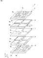
- FIG. 1 is a schematic front sectional view showing a main part of a fuel cell stack according to a first embodiment of the present invention. It is a disassembled perspective view of one fuel battery cell used for the fuel cell stack of the 1st Embodiment of this invention. It is a top view of one fuel cell used for the fuel cell stack concerning a 1st embodiment.
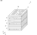
- 1 is a perspective view schematically showing a fuel cell stack according to a first embodiment.
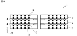
- FIG. 5 is a schematic front sectional view showing the main part of the fuel cell stack according to the second embodiment.
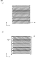
- FIG. 6A is a plan view of a connecting portion of an example of the fuel cell stack according to the second embodiment as viewed from above.
- FIG. 6B is a plan view of the heat conducting portion of an example of the fuel cell stack according to the second embodiment as viewed from above.
- FIG. 1 is a schematic front sectional view of a fuel cell stack according to a first embodiment of the present invention.
- the upper fuel cell 2 and the middle fuel cell 2 are joined via a joint 4, and the middle fuel cell 2 and the lower fuel cell 2 are joined. 4 is joined.
- three fuel cells 2, 2, and 2 are shown.
- a structure in which the fuel cells 2 and 2 on both sides are stacked via another joint 4. Furthermore, it is lined up.
- FIG. 1 only the positions where the fuel cells 2, 2 and 2 are provided are schematically shown. Details of one fuel cell 2 will be described with reference to FIGS. 2 and 3.
- the fuel cell 2 has a solid oxide electrolyte layer 7.
- the solid oxide electrolyte layer 7 is made of a ceramic having high ionic conductivity. Examples of such materials include stabilized zirconia and partially stabilized zirconia. More specifically, zirconia stabilized by Y or Sc is mentioned. Examples of the stabilized zirconia include 10 mol% yttria stabilized zirconia (10YSZ) and 11 mol% scandia stabilized zirconia (11ScSZ). Examples of the partially stabilized zirconia include 3 mol% yttria partially stabilized zirconia (3YSZ).
- the material constituting the solid oxide electrolyte layer 7 is not limited to the above, Sm and Gd-doped ceria-based oxide and, La 0.8 Sr 0.2 Ga 0.8 Me 0.2 O It may be formed of a perovskite oxide such as (3- ⁇ ) . ⁇ represents a positive number less than 3.
- the solid oxide electrolyte layer 7 is provided with a through hole 7a and a through hole 7b.
- the through hole 7a constitutes a fuel gas flow path.
- the through hole 7b constitutes an air flow path through which air as an oxidant gas passes.
- the fuel electrode layer 6 is laminated above the solid oxide electrolyte layer 7.
- the fuel electrode layer 6 can be composed of yttria-stabilized zirconia containing Ni, scandia-stabilized zirconia containing Ni, or the like.
- the fuel electrode layer 6 is provided with a slit 6a constituting a fuel gas flow path and a slit 6b constituting an air flow path.
- the separator 5 is laminated on the fuel electrode layer 6.
- the separator 5 can be formed of stabilized zirconia, partially stabilized zirconia, or the like.
- Through holes 5 a and 5 b are formed in the separator 5.
- the through hole 5a constitutes a fuel gas flow path.
- the through hole 5b constitutes an air flow path.
- the separator 5 is provided with a plurality of interconnectors 5c for taking out electricity so as to penetrate the lower surface from the upper surface of the separator 5. That is, each interconnector 5c is formed by a via-hole conductor. The plurality of interconnectors 5 c are electrically connected to the fuel electrode layer 6.
- the material of the interconnector 5c is not particularly limited.
- the interconnector 5c includes, for example, an Ag—Pd alloy, an Ag—Pt alloy, lanthanum chromite (LaCrO 3 ) added with an alkaline earth metal, lanthanum ferrate (LaFeO 3 ), lanthanum strontium manganite (LSM). ) Or the like.
- an air electrode layer 8 and a separator 9 are laminated below the solid oxide electrolyte layer 7.
- the air electrode layer 8 is provided with a slit 8a that constitutes a fuel gas passage and a slit 8b that constitutes an air passage.
- the air electrode layer 8 is preferably made of a porous material having high electron conductivity.
- Such an air electrode layer 8 includes, for example, scandia-stabilized zirconia (ScSZ), ceria doped with Gd, indium oxide doped with Sn, PrCoO 3 oxide, LaCoO oxide, or LaMoO 3 oxide. It can be formed by things.
- Examples of the LaMoO 3 oxide include La 0.8 Sr 0.2 MnO 3 (hereinafter abbreviated as LSM) and La 0.6 Ca 0.4 MnO 3 .
- the separator 9 is configured in the same manner as the separator 5. Therefore, it has the through-hole 9a which comprises a fuel gas flow path, the through-hole 9b which comprises an air flow path, and the several interconnector 9c.
- the fuel battery cell 2 is prepared by mixing and molding the materials shown above with a binder and a solvent for each component, preparing a green sheet having a predetermined shape, and laminating and crimping these green sheets, It can obtain through the baking process integrated by co-sintering the obtained laminated body.
- FIG. 3 shows a plan view of the single fuel cell 2.
- the fuel battery cell 2 has a cross-shaped flow path component 2a and four power generation units 2b, 2c, 2d, and 2e partitioned by the flow path component 2a when viewed in plan. .
- the interconnector 5c is exposed on the upper surfaces of the power generation units 2b to 2e.
- FIG. 4 is a perspective view showing the fuel cell stack 1. As shown in FIG. 4, in the fuel cell stack 1, the fuel cells 2, 2, 2 are stacked via joints 4, 4.
- the fuel cell stack 1 is characterized by the structure of a joint 4 that joins the fuel battery cell 2 and the fuel battery cell 2 together.
- the joint 4 physically joins and integrates the upper fuel cell 2 and the lower fuel cell 2, and electrically connects the upper fuel cell 2 and the lower fuel cell 2 in series. Connected.
- the joint portion 4 is provided with a connection portion 10 in order to electrically connect the upper fuel cell 2 and the lower fuel cell 2.
- the connecting portion 10 is disposed at a position corresponding to the conductive via 11 provided in the fuel cell 2 with a space therebetween.
- the conductive via 11 is provided penetrating through the separator 5 or the separator 9 in the stacking direction, and electrically connects the fuel electrode layer 6 or the air electrode layer 8 and the connection portion 10.
- connection portions 10 are arranged with a space therebetween, that is, by providing the connection portion 10 non-formation region in the joint portion 4, it is possible to suppress heat from being trapped inside the fuel cell stack 1. be able to. Furthermore, since the connection part 10 is arrange
- the conductive via 11 is, for example, a surface electrode formed of a conductive oxide, and takes out electricity generated by the fuel cell to the outside.
- the fuel cell stack 1 can be stacked by electrically connecting the surface electrodes of the opposing fuel cells 2 via a conductive material, and the output can be increased.
- the output increases (when the amount of power generation increases)
- the heat generated by the power generation is trapped inside the fuel cell stack 1 and the temperature distribution is generated in the plane of the fuel cell 2, which may cause cracks. Get higher.
- the conventional joining between the fuel cells 2 and 2 has been performed by a method such as disposing a sheet-like conductive material over the entire joint.
- a method of alternately stacking (stacking) fuel cells and metal separators using a metal separator is also employed. Since the metal separator itself has a relatively high thermal conductivity, it is possible to flatten the temperature distribution in the fuel cell. However, since the fuel cell and the metal separator are electrically connected between different materials, the reliability is not sufficient. Moreover, Cr vapor
- the material constituting the connecting portion 10, LaSrMnO 3 is a conductive ceramic material: made of (LSM Lanthanum Strontium Manganite).
- the material which comprises the said connection part 10 is not specifically limited, What is necessary is just to have favorable electroconductivity.
- a conductive ceramic material a material having a crystal structure of ABO 3 or A 2 BO 4 (A: one kind of rare earth, B: one kind of transition element) can be mentioned.
- the aforementioned LSM, LaSrCoO 3 , LaSrCoFeO 3 , MnCoO 3 , SmSrCoO 3 , LaCaMnO 3 , LaCaCoO 3 , LaCaCoFeO 3 , LaNiFeO 3 , (LaSr) 2 NiO 4, etc. can be used. Since these materials have electrical conductivity, the electrical resistance between the fuel cells can be reduced by using the connection portion 10 and the stack characteristics can be improved.
- a noble metal such as Au or Pt can be used as the material constituting the connecting portion 10, but it is preferable to use a material such as LSM because the noble metal is expensive.
- connection part 10 Since the extraction of electricity from the fuel battery cell 2 is performed by the conductive via 11, the connecting portion 10 disposed between the fuel battery cells 2 only needs to exist at least on the surface electrode (conductive via 11). Therefore, the connection part 10 is preferably provided in a dot shape on the conductive via 11. When the area of the connection part 10 in plan view is larger than the area of the conductive via 11 in plan view, the resistance value of the connection part can be lowered, which is preferable. Alternatively, the material of the connection part 10 can be made into a paste and applied in a meandering manner so as to trace the adjacent conductive vias 11. As described above, the connection portion 10 is continuously provided at positions corresponding to the plurality of conductive vias 11, thereby facilitating manufacturing.
- FIG. 5 is a schematic front sectional view of a fuel cell stack according to the second embodiment of the present invention.
- the heat conduction part 12 made of a material having a higher thermal conductivity than the connection part 10 is provided in the interval of the plurality of connection parts 10.
- FIG. 6 shows an example of the shapes of the connection part 10 and the heat conduction part 12.
- FIG. 6A is a plan view of a connecting portion of an example of the fuel cell stack according to the second embodiment as viewed from above.
- FIG. 6B is a plan view of the heat conducting portion of an example of the fuel cell stack according to the second embodiment as viewed from above.
- the connection part 10 in FIG. 6A is provided in a meandering manner so as to cover the conductive via 11.
- the connection part 10 is formed in a meandering shape, the connection part 10 is connected to one line.
- “a plurality of connection parts are arranged with a space between each other” means, for example, FIG. 6 (a), when the cross section of the vicinity of the center is viewed with a vertical line, it is sufficient that there is a portion where a plurality of connecting portions are arranged with intervals, and the connecting portions may be connected at the end portions. Absent.
- a metal foil processed into a comb-teeth shape as shown in FIG. 6B is opposed to the heat conducting portion 12 between the meandering connection portions 10 shown in FIG. Two pieces are inserted.
- the heat conduction part 12 is substantially the same height as the connection part 10 in the direction in which the fuel cells (2, 2, 2) are stacked.
- substantially the same height means that the height can include an error as long as the connection between the fuel cells of the connection portion 10 is not hindered.
- the height of the heat conduction part 12 substantially the same as the height of the connection part 10, it is possible to achieve both suppression of heat trapping inside the fuel cell stack 1 and suppression of thickening of the fuel cell stack. Therefore, it is preferable. Further, in the structure of the present embodiment in which the heat conducting portion 12 is provided in the space between the connecting portions 10, it is not necessary to add a new layer, so that the in-plane temperature distribution can be reduced in a small space. Therefore, it is useful for reducing the size of the fuel cell stack.
- the heat conduction part 12 is made of a material mainly composed of at least one selected from the group consisting of Pt, Pd, Ag, Au, Ru, Rh, Ni, Fe, Cr, Cu, Ti, Co, and Si. It is preferable to become. In this specification, “mainly” means to occupy 1/2 or more.
- the metal material is more preferably a low-cost material that has high thermal conductivity and can withstand the operating temperature environment of the solid oxide fuel cell.
- NCA-1 manufactured by Nisshin Steel
- it is preferable that Al is added as a trace element. This is because the Al element forms an Al 2 O 3 layer on the metal surface at a high temperature, and the oxidation resistance becomes very high.
- connection portion 10 is provided in a meandering manner so as to cover the conductive via 11, but the present invention is not limited to this. It is also preferable to provide the connection part 10 on the conductive via 11 in a dot shape.
- the metal foil used as the heat conduction part 12 may be a mesh in which the position of the conductive via 11 is a through hole, for example.
- the in-plane temperature distribution caused by the heat generated by the power generation while improving the reliability of the electrical connection between the cells. It is possible to provide a solid oxide fuel cell stack in which the cracks are flattened and cracks are suppressed.
Landscapes
- Life Sciences & Earth Sciences (AREA)
- Engineering & Computer Science (AREA)
- Manufacturing & Machinery (AREA)
- Sustainable Development (AREA)
- Sustainable Energy (AREA)
- Chemical & Material Sciences (AREA)
- Chemical Kinetics & Catalysis (AREA)
- Electrochemistry (AREA)
- General Chemical & Material Sciences (AREA)
- Fuel Cell (AREA)
Abstract
固体酸化物形燃料電池セルの積層(スタック化)において、セル間の電気的接続の信頼性を向上しつつ、発電に伴って発生する熱に起因するセル面内温度分布を平坦化し、クラックの発生を抑制した固体酸化物形燃料電池スタックを提供する。複数の燃料電池セルが積層されている構造を有し、燃料電池セル2は、固体酸化物電解質層7と、固体酸化物電解質層7を介して積層された燃料極層6および空気極層8と、燃料極層6および空気極層8の外側に積層された一組のセパレータ5,9とを備え、燃料電池セル2同士が積層されている部分において、一方の燃料電池セルと、他方の燃料電池セルとを電気的に接続する複数の接続部10と、燃料極層6または空気極層8と接続部10とを電気的に接続し、セパレータ5,9内を積層方向に貫通する導電ビア11と、を有し、複数の接続部10は導電ビア11に対応する位置に、相互に間隔を有して配置されている、固体酸化物形燃料電池スタック1。
Description
この発明は、複数の固体酸化物形の燃料電池セルが積層されている固体酸化物形燃料電池スタックに関する。
固体酸化物形燃料電池(SOFC:Solid Oxide Fuel Cell、固体電解質形燃料電池ともいう)は、燃料極(アノード):H2+O2-→H2O+2e-、空気極(カソード):(1/2)O2+2e-→O2-の反応により、電気エネルギーを取り出す装置である。電気エネルギーを連続的に取り出すため、反応を連続的に行う必要があり、そのため、アノードガスとしての燃料ガス(例えばH2)およびカソードに供給されるカソードガスとしての空気(O2)等の酸化剤ガスを連続して供給する。固体酸化物形燃料電池においては、十分な電圧を得るために、複数の燃料電池セルが積層されている。それによって、燃料電池(燃料電池スタック)が構成されている。燃料電池スタックは、複数の燃料電池セルを電気的に接続する。前記接続の信頼性を高めるために、一方の燃料電池セルと他方の燃料電池セルとの間に金属層を配置し、前記金属層と燃料電池セル2を電気的に接続するように前記金属層と前記燃料電池セルとの間に導電材層を設けることが提案されている(例えば、特許文献1参照)。
しかしながら、前記の場合、セラミックからなる前記燃料電池セルと、前記金属からなる金属層とは、熱膨張係数が異なっており、熱サイクルが加わった場合における接続性に改善の余地がある。一方、金属層の代わりに導電性セラミックからなる層を使用した場合には熱がこもり易くなってしまうという問題があった。
本発明は上記問題点を解決するものであり、固体酸化物形燃料電池セルの積層(スタック化)において、セル間の電気的接続の信頼性を向上しつつ、発電に伴って発生する熱に起因するセル面内温度分布を平坦化し、クラックの発生を抑制した固体酸化物形燃料電池スタックを提供することを目的とする。
上記目的を達成するために、本発明の固体酸化物形燃料電池スタックは、複数の燃料電池セルが積層されている構造を有する。前記燃料電池セルは、固体酸化物電解質層と、前記固体酸化物電解質層を介して積層された燃料極層および空気極層と、前記燃料極層および前記空気極層の外側に積層された一組のセパレータとを備え、前記燃料電池セル同士が積層されている部分において、一方の燃料電池セルと、他方の燃料電池セルとを電気的に接続する複数の接続部と、前記燃料極層または前記空気極層と前記接続部とを電気的に接続し、前記セパレータ内を積層方向に貫通する導電ビアと、を有し、前記複数の接続部は前記導電ビアに対応する位置に、相互に間隔を有して配置されている。
本発明の固体酸化物形燃料電池スタックのある特定の局面においては、前記複数の接続部が有する前記間隔内に、前記接続部よりも熱伝導率の高い材料からなる熱伝導部が設けられている。
本発明の固体酸化物形燃料電池スタックにおいて、前記熱伝導部は、前記燃料電池セル同士が積層されている方向において、前記接続部の高さと略同一の高さであることが好ましい。
本発明の固体酸化物形燃料電池スタックにおいて、前記熱伝導部は、櫛歯形状であることが好ましい。
本発明の固体酸化物形燃料電池スタックにおいて、前記熱伝導部は、Pt、Pd、Ag、Au、Ru、Rh、Ni、Fe、Cr、Cu、Ti、Co、Siからなる群から選択された少なくとも1種を主体とする材料からなることが好ましい。
本発明の固体酸化物形燃料電池スタックにおいて、前記接続部は、LaSrMnO3、LaSrCoO3、LaSrCoFeO3、MnCoO3、SmSrCoO3、LaCaMnO3、LaCaCoO3、LaCaCoFeO3、LaNiFeO3、(LaSr)2NiO4からなる群から選択された少なくとも1種の材料を主体とする導電セラミックスであることが好ましい。
本発明の固体酸化物形燃料電池スタックによれば、固体酸化物形燃料電池セルの積層(スタック化)において、セル間の電気的接続の信頼性を向上しつつ、発電に伴って発生する熱に起因するセル面内温度分布を平坦化し、クラックの発生を抑制した固体酸化物形燃料電池スタックを提供することができる。
この発明の上述の目的,その他の目的,特徴および利点は、図面を参照して行う以下の実施例の詳細な説明から一層明らかとなろう。
以下、この発明の実施の形態を、図面を参照しながら説明する。ただし、本発明は、以下の例に限定および制限されない。なお、以下で参照する図面は、模式的に記載されたものであり、図面に描画された物体の寸法の比率などは、現実の物体の寸法の比率などとは異なる場合がある。図面相互間においても、物体の寸法比率等が異なる場合がある。また、各実施形態は例示であり、異なる実施形態で示した構成の部分的な置換または組み合わせが可能であることは言うまでもない。第2の実施形態以降では、第1の実施形態と共通の事柄についての記述を省略し、異なる点についてのみ説明する。とくに、同様の構成による同様の作用効果については、実施形態毎には逐次言及しない。
(第1の実施形態)
図1は、本発明の第1の実施形態に係る燃料電池スタックの略図的正面断面図である。燃料電池スタック1においては、上段の燃料電池セル2と中段の燃料電池セル2とが接合部4を介して接合されており、中段の燃料電池セル2と下段の燃料電池セル2とが接合部4を介して接合されている。図1においては、3つの燃料電池セル2,2,2を示したが、本実施形態においては、さらに他の接合部4を介して両側の燃料電池セル2,2が積層されている構造がさらに連ねられている。
図1は、本発明の第1の実施形態に係る燃料電池スタックの略図的正面断面図である。燃料電池スタック1においては、上段の燃料電池セル2と中段の燃料電池セル2とが接合部4を介して接合されており、中段の燃料電池セル2と下段の燃料電池セル2とが接合部4を介して接合されている。図1においては、3つの燃料電池セル2,2,2を示したが、本実施形態においては、さらに他の接合部4を介して両側の燃料電池セル2,2が積層されている構造がさらに連ねられている。
また、図1においては、燃料電池セル2,2,2は、その設けられている位置のみを略図的に示している。図2および図3を参照して、1つの燃料電池セル2の詳細を説明する。
図2に示すように、燃料電池セル2は、固体酸化物電解質層7を有する。固体酸化物電解質層7は、イオン導電性が高いセラミックスからなる。このような材料としては、例えば、安定化ジルコニアや部分安定化ジルコニアなどを挙げることができる。より具体的には、YやScにより安定化されたジルコニアが挙げられる。安定化ジルコニアとしては、例えば、10モル%イットリア安定化ジルコニア(10YSZ)、11モル%スカンジア安定化ジルコニア(11ScSZ)などを挙げることができる。部分安定化ジルコニアとしては、例えば、3モル%イットリア部分安定化ジルコニア(3YSZ)などを挙げることができる。
なお、上記固体酸化物電解質層7を構成する材料は上記に限定されず、SmやGdがドープされたセリア系酸化物や、La0.8Sr0.2Ga0.8Me0.2O(3-δ)などのペロブスカイト型酸化物などにより形成してもよい。なお、δは、3未満の正の数を示す。
固体酸化物電解質層7には、貫通孔7aと貫通孔7bとが設けられている。貫通孔7aは、燃料ガス流路を構成している。貫通孔7bは、酸化剤ガスとしての空気を通す空気流路を構成している。
固体酸化物電解質層7の上方に燃料極層6が積層されている。燃料極層6は、Niを含むイットリア安定化ジルコニアや、Niを含むスカンジア安定化ジルコニアなどにより構成することができる。燃料極層6には、燃料ガス流路を構成するスリット6aと、空気流路を構成するスリット6bとが設けられている。
上記燃料極層6上にセパレータ5が積層されている。セパレータ5は、安定化ジルコニアや部分安定化ジルコニアなどにより形成され得る。セパレータ5に、貫通孔5a,5bが形成されている。貫通孔5aは、燃料ガス流路を構成している。貫通孔5bは、空気流路を構成している。
他方、セパレータ5には、電気を取り出すための複数本のインターコネクタ5cがセパレータ5の上面から下面を貫くように設けられている。すなわち、ビアホール導体により各インターコネクタ5cが形成されている。複数本のインターコネクタ5cは、上記燃料極層6に電気的に接続されている。
インターコネクタ5cの材質は、特に限定されない。インターコネクタ5cは、例えば、Ag-Pd合金、Ag-Pt合金、アルカリ土類金属を添加したランタンクロマイト(LaCrO3)、ランタンフェレート(LaFeO3)や、ランタンストロンチウムマンガナイト(LSM:Lanthanum Strontium Manganite)等により形成することができる。
他方、固体酸化物電解質層7の下方には、空気極層8およびセパレータ9が積層されている。空気極層8には、燃料ガス流路を構成するスリット8aと、空気流路を構成するスリット8bとが設けられている。空気極層8は、電子伝導性が高く、かつ多孔質の材料からなることが好ましい。このような空気極層8は、例えば、スカンジア安定化ジルコニア(ScSZ)、Gdがドープされたセリア、Snがドープされた酸化インジウム、PrCoO3系酸化物、LaCoO系酸化物、またはLaMoO3系酸化物などにより形成することができる。LaMoO3系酸化物としては、例えば、La0.8Sr0.2MnO3(以下においてLSMと略す)や、La0.6Ca0.4MnO3などが挙げられる。
セパレータ9はセパレータ5と同様に構成されている。従って、燃料ガス流路を構成する貫通孔9aと、空気流路を構成する貫通孔9bと、複数本のインターコネクタ9cとを有する。
燃料電池セル2は、各構成部材について、上記に示す材料をバインダーおよび溶媒と混合、成形して、所定の形状のグリーンシートとして準備し、これらグリーンシートを積層して圧着する積層圧着工程と、得られた積層体を共焼結することによって一体化する焼成工程を経て、得ることができる。
図3は、この単一の燃料電池セル2の平面図を示す。図3に示すように燃料電池セル2は、平面視した場合、十字状の流路構成部2aと、流路構成部2aで区画された4つの発電部2b,2c,2d,2eとを有する。そして、発電部2b~2eの上面には上記インターコネクタ5cが露出している。
本実施形態の燃料電池スタック1においては、このような燃料電池セル2が複数積層されている。図4は、燃料電池スタック1を示す斜視図である。図4に示すように、燃料電池スタック1においては、燃料電池セル2,2,2は接合部4,4を介して積層されている。
図1に示すように、本実施形態の燃料電池スタック1の特徴は、燃料電池セル2と燃料電池セル2とを接合している接合部4の構成にある。
接合部4は、上方の燃料電池セル2と下方の燃料電池セル2とを物理的に接合し一体化するとともに、上方の燃料電池セル2と下方の燃料電池セル2とを電気的に直列に接続している。接合部4には、上方の燃料電池セル2と下方の燃料電池セル2とを電気的に接続するために、接続部10が設けられている。接続部10は、燃料電池セル2に設けられた導電ビア11に対応する位置に、相互に間隔を有して配置されている。導電ビア11は、セパレータ5内またはセパレータ9内を積層方向に貫通して設けられており、燃料極層6または空気極層8と接続部10とを電気的に接続する。このように、接続部10が相互に間隔を有して配置される、すなわち、接合部4内に接続部10非形成領域を設けることで、熱が燃料電池スタック1内部にこもるのを抑制することができる。さらに、接続部10は、間隔を有して配置されているので、単位体積当たりの表面積は大きくなる。そのため、接続部等の形成の際に、脱脂性が向上するという利点もある。
導電ビア11は、例えば、導電性酸化物で形成された表面電極であり、燃料電池セルで発電された電気を外部に取り出す。燃料電池スタック1は、対向する燃料電池セル2の表面電極を、導電性材料を介して電気的に接続することでスタックし、出力を上げることができる。しかし、出力が上がると(発電量が増えると)、発電に伴って発生する熱が燃料電池スタック1内部にこもり、燃料電池セル2の面内に温度分布が生じることで、クラック発生の懸念が高くなる。従来の燃料電池セル2,2間の接合は、接合部全面に、例えばシート状の導電性材料を配置する等の方法で行われていた。あるいは、金属製のセパレータを用いて、燃料電池セルと金属セパレータとを交互に積層(スタック)するという方法も採用されている。金属セパレータは、それ自体が相対的に熱伝導率が高いので、燃料電池セル内の温度分布を平坦化することは可能である。しかし、燃料電池セルと金属セパレータとの間は、異種素材間の電気接続となるため、信頼性が十分とはいえない。また、金属セパレータからCr蒸気が発生する場合がある。Cr蒸気が燃料電池セルの電極を被毒すると、燃料電池の耐久性に問題が生じるおそれがある。
そこで、電気接続の信頼性を向上させるとともに、Cr被毒も問題とならず、かつ、燃料電池セル内の温度分布の発生を抑制してクラック発生も抑制可能な燃料電池スタックを実現させたのが、本発明である。
本実施形態においては、接続部10を構成する材料は、導電セラミックス材料であるLaSrMnO3(LSM:Lanthanum Strontium Manganite)からなる。もっとも、上記接続部10を構成する材料は特に限定されず、良好な導電性を有していればよい。例えば、導電セラミックス材料であれば、ABO3あるいはA2BO4(A:希土類を1種含む、B:遷移元素を1種含む)の結晶構造を有する材料があげられる。具体的には、前述のLSM、LaSrCoO3、LaSrCoFeO3、MnCoO3、SmSrCoO3、LaCaMnO3、LaCaCoO3、LaCaCoFeO3、LaNiFeO3、(LaSr)2NiO4などを使用することができる。これらの材料は、電気伝導性を持つため、接続部10とすることで燃料電池セル間の電気抵抗を小さくすることができ、スタック特性を向上させることができる。接続部10を構成する材料としては、AuやPtなどの貴金属を用いることもできるが、貴金属は高価であるため、LSM等の材料を用いることが好ましい。
燃料電池セル2からの電気の取り出しは、導電ビア11によって行われるので、燃料電池セル2間に配置する接続部10は、この表面電極(導電ビア11)上に少なくとも存在していればよい。したがって、接続部10は、導電ビア11の上に点状に設けるとよい。接続部10の平面視での面積を、導電ビア11の平面視での面積よりも大きくすると、接続部の抵抗値を下げることができ、好ましい。また、接続部10の材料をペースト化しておき、隣接する導電ビア11をなぞるように蛇行状に塗布して形成することもできる。このように、接続部10を複数の導電ビア11に対応する位置に連続して設けることで、製造が容易になる。
(第2の実施形態)
図5は、本発明の第2の実施形態に係る燃料電池スタックの略図的正面断面図である。本実施形態においては、複数の接続部10が有する前記間隔内に、接続部10よりも熱伝導率の高い材料からなる熱伝導部12が設けられている。
図5は、本発明の第2の実施形態に係る燃料電池スタックの略図的正面断面図である。本実施形態においては、複数の接続部10が有する前記間隔内に、接続部10よりも熱伝導率の高い材料からなる熱伝導部12が設けられている。
図6に、接続部10および熱伝導部12の形状の一例を示す。図6(a)は、第2の実施形態に係る燃料電池スタックの一例の接続部を上面から見た平面図である。図6(b)は、第2の実施形態に係る燃料電池スタックの一例の熱伝導部を上面から見た平面図である。図6(a)の接続部10は、導電ビア11上をカバーするように、蛇行状に設けられている。なお、蛇行状に接続部10を形成すると、接続部10が1本のラインにつながることとなるが、本発明における「複数の接続部が相互に間隔を有して配置」とは、例えば図6(a)において中央付近を縦のラインで断面を見たときに、複数の接続部が間隔を有して配置されている部分があればよく、端部において接続部がつながっていても構わない。
本実施形態においては、図6(a)に示す蛇行状の接続部10の間に、熱伝導部12として、図6(b)に示すような櫛歯状に加工した金属箔を向かい合わせて2枚が挿入されている。接続部10よりも熱伝導率が高い金属箔を熱伝導部12として設けることで、燃料電池セル2の面内の温度分布を緩和して、クラック発生を抑制することができる。ここで、熱伝導部12は、燃料電池セル同士(2、2、2)が積層されている方向において、接続部10の高さと略同一の高さであることが好ましい。ここで略同一の高さとは、接続部10の燃料電池セル間の接続を阻害しない範囲で、誤差を含むことのできる高さであることを意味する。熱伝導部12の高さを接続部10の高さと略同一にすることによって、熱が燃料電池スタック1内部にこもることの抑制と、燃料電池スタックの厚肉化抑制とを両立させることができるので、好ましい。また、接続部10の間のスペースに熱伝導部12を設ける本実施形態の構造では、新たな層を追加する必要がないため、省スペースで面内温度分布の緩和ができる。したがって、燃料電池スタックの小型化にも有用である。
熱伝導部12は、Pt、Pd、Ag、Au、Ru、Rh、Ni、Fe、Cr、Cu、Ti、Co、Siからなる群からなる群から選択された少なくとも1種を主体とする材料からなることが好ましい。なお、本明細書において、「主体とする」とは、1/2以上を占めることを意味する。金属材料としては、熱伝導率が高く、かつ、固体酸化物形燃料電池の動作温度環境下に耐えうる、低コストの材料であることがより好ましい。例えば、フェライト系ステンレスを基本とした組成であるNCA-1(日新製鋼製)を好ましく用いることができる。フェライト系ステンレスにおいては、微量元素としてAlが添加されていることが好ましい。Al元素は、高温化において金属表面にAl2O3層を形成し、耐酸化性が非常に高くなるためである。
本実施形態では、接続部10は、導電ビア11上をカバーするように、蛇行状に設けられているが、本発明はこれに限定されない。接続部10は、導電ビア11上に点状に設けることも好ましい。接続部10を点状に設ける場合、熱伝導部12として用いる金属箔を、例えば、導電ビア11の位置が貫通孔であるようなメッシュとすることもできる。
このように、本発明によると、固体酸化物形燃料電池セルのスタック化において、セル間の電気的接続の信頼性を向上しつつ、発電に伴って発生する熱に起因するセル面内温度分布を平坦化し、クラックの発生を抑制した固体酸化物形燃料電池スタックを提供することができる。
1 燃料電池スタック
2 燃料電池セル
2a 流路構成部
2b,2c,2d,2e 発電部
4 接合部
5 セパレータ
5a,5b 貫通孔
5c インターコネクタ
6 燃料極層
6a,6b スリット
7 固体酸化物電解質層
7a,7b 貫通孔
8 空気極層
8a,8b スリット
9 セパレータ
9a,9b 貫通孔
9c インターコネクタ
10 接続部
11 導電ビア
12 熱伝導部
2 燃料電池セル
2a 流路構成部
2b,2c,2d,2e 発電部
4 接合部
5 セパレータ
5a,5b 貫通孔
5c インターコネクタ
6 燃料極層
6a,6b スリット
7 固体酸化物電解質層
7a,7b 貫通孔
8 空気極層
8a,8b スリット
9 セパレータ
9a,9b 貫通孔
9c インターコネクタ
10 接続部
11 導電ビア
12 熱伝導部
Claims (6)
- 複数の燃料電池セルが積層されている構造を有する固体酸化物形燃料電池スタックであって、
前記燃料電池セルは、固体酸化物電解質層と、前記固体酸化物電解質層を介して積層された燃料極層および空気極層と、前記燃料極層および前記空気極層の外側に積層された一組のセパレータとを備え、
前記燃料電池セル同士が積層されている部分において、一方の燃料電池セルと、他方の燃料電池セルとを電気的に接続する複数の接続部と、
前記燃料極層または前記空気極層と前記接続部とを電気的に接続し、前記セパレータ内を積層方向に貫通する導電ビアと、を有し、
前記複数の接続部は前記導電ビアに対応する位置に、相互に間隔を有して配置されている、固体酸化物形燃料電池スタック。 - 前記複数の接続部が有する前記間隔内に、前記接続部よりも熱伝導率の高い材料からなる熱伝導部が設けられている、請求項1記載の固体酸化物形燃料電池スタック。
- 前記熱伝導部は、前記燃料電池セル同士が積層されている方向において、前記接続部の高さと略同一の高さである、請求項2記載の固体酸化物形燃料電池スタック。
- 前記熱伝導部は、櫛歯形状である、請求項2または3記載の固体酸化物形燃料電池スタック。
- 前記熱伝導部は、Pt、Pd、Ag、Au、Ru、Rh、Ni、Fe、Cr、Cu、Ti、Co、Siからなる群から選択された少なくとも1種を主体とする材料からなる、請求項2から4のいずれか1項に記載の固体酸化物形燃料電池スタック。
- 前記接続部は、LaSrMnO3、LaSrCoO3、LaSrCoFeO3、MnCoO3、SmSrCoO3、LaCaMnO3、LaCaCoO3、LaCaCoFeO3、LaNiFeO3、(LaSr)2NiO4からなる群から選択された少なくとも1種の材料を主体とする導電セラミックスである、請求項1から5のいずれか1項に記載の固体酸化物形燃料電池スタック。
Priority Applications (1)
| Application Number | Priority Date | Filing Date | Title |
|---|---|---|---|
| JP2017552322A JP6460261B2 (ja) | 2015-11-24 | 2016-10-26 | 固体酸化物形燃料電池スタック |
Applications Claiming Priority (2)
| Application Number | Priority Date | Filing Date | Title |
|---|---|---|---|
| JP2015228490 | 2015-11-24 | ||
| JP2015-228490 | 2015-11-24 |
Publications (1)
| Publication Number | Publication Date |
|---|---|
| WO2017090367A1 true WO2017090367A1 (ja) | 2017-06-01 |
Family
ID=58763398
Family Applications (1)
| Application Number | Title | Priority Date | Filing Date |
|---|---|---|---|
| PCT/JP2016/081698 Ceased WO2017090367A1 (ja) | 2015-11-24 | 2016-10-26 | 固体酸化物形燃料電池スタック |
Country Status (2)
| Country | Link |
|---|---|
| JP (1) | JP6460261B2 (ja) |
| WO (1) | WO2017090367A1 (ja) |
Cited By (3)
| Publication number | Priority date | Publication date | Assignee | Title |
|---|---|---|---|---|
| CN110330685A (zh) * | 2019-07-09 | 2019-10-15 | 成都爻能节能科技有限公司 | 一种陶瓷材料及用该材料制得的节能装置 |
| CN112456536A (zh) * | 2020-11-12 | 2021-03-09 | 西南大学 | 一种固态电解质材料、氟离子电池及其制备方法 |
| JP2022015903A (ja) * | 2020-07-10 | 2022-01-21 | 日産自動車株式会社 | 固体酸化物形燃料電池 |
Citations (4)
| Publication number | Priority date | Publication date | Assignee | Title |
|---|---|---|---|---|
| WO2011138915A1 (ja) * | 2010-05-07 | 2011-11-10 | 株式会社 村田製作所 | 高温構造材料、固体電解質形燃料電池用構造体および固体電解質形燃料電池 |
| WO2013012058A1 (ja) * | 2011-07-21 | 2013-01-24 | 株式会社村田製作所 | 固体酸化物形燃料電池用電気的接続材、固体酸化物形燃料電池用接合材および固体酸化物形燃料電池 |
| WO2015029983A1 (ja) * | 2013-08-30 | 2015-03-05 | 株式会社村田製作所 | セパレータ及び燃料電池 |
| WO2015115125A1 (ja) * | 2014-01-28 | 2015-08-06 | 株式会社村田製作所 | 固体酸化物燃料電池及び固体酸化物燃料電池スタック |
-
2016
- 2016-10-26 WO PCT/JP2016/081698 patent/WO2017090367A1/ja not_active Ceased
- 2016-10-26 JP JP2017552322A patent/JP6460261B2/ja not_active Expired - Fee Related
Patent Citations (4)
| Publication number | Priority date | Publication date | Assignee | Title |
|---|---|---|---|---|
| WO2011138915A1 (ja) * | 2010-05-07 | 2011-11-10 | 株式会社 村田製作所 | 高温構造材料、固体電解質形燃料電池用構造体および固体電解質形燃料電池 |
| WO2013012058A1 (ja) * | 2011-07-21 | 2013-01-24 | 株式会社村田製作所 | 固体酸化物形燃料電池用電気的接続材、固体酸化物形燃料電池用接合材および固体酸化物形燃料電池 |
| WO2015029983A1 (ja) * | 2013-08-30 | 2015-03-05 | 株式会社村田製作所 | セパレータ及び燃料電池 |
| WO2015115125A1 (ja) * | 2014-01-28 | 2015-08-06 | 株式会社村田製作所 | 固体酸化物燃料電池及び固体酸化物燃料電池スタック |
Cited By (5)
| Publication number | Priority date | Publication date | Assignee | Title |
|---|---|---|---|---|
| CN110330685A (zh) * | 2019-07-09 | 2019-10-15 | 成都爻能节能科技有限公司 | 一种陶瓷材料及用该材料制得的节能装置 |
| CN110330685B (zh) * | 2019-07-09 | 2021-07-30 | 成都爻能节能科技有限公司 | 一种陶瓷材料及用该材料制得的节能装置 |
| JP2022015903A (ja) * | 2020-07-10 | 2022-01-21 | 日産自動車株式会社 | 固体酸化物形燃料電池 |
| JP7563013B2 (ja) | 2020-07-10 | 2024-10-08 | 日産自動車株式会社 | 固体酸化物形燃料電池 |
| CN112456536A (zh) * | 2020-11-12 | 2021-03-09 | 西南大学 | 一种固态电解质材料、氟离子电池及其制备方法 |
Also Published As
| Publication number | Publication date |
|---|---|
| JP6460261B2 (ja) | 2019-01-30 |
| JPWO2017090367A1 (ja) | 2018-05-24 |
Similar Documents
| Publication | Publication Date | Title |
|---|---|---|
| CN107408711B (zh) | 燃料电池堆 | |
| CN103703599B (zh) | 固体氧化物燃料电池用电连接材料、固体氧化物燃料电池、固体氧化物燃料电池模块以及固体氧化物燃料电池的制造方法 | |
| JP7428686B2 (ja) | 電気分解耐性の空気側電極を含む固体酸化物形電解槽セル | |
| JP6460261B2 (ja) | 固体酸化物形燃料電池スタック | |
| JP6204106B2 (ja) | 燃料電池セル及び燃料電池セルスタック | |
| JP6389133B2 (ja) | 燃料電池スタック | |
| JP5373668B2 (ja) | 固体酸化物形燃料電池用単セルおよび固体酸化物形燃料電池 | |
| JP2016039004A (ja) | 燃料電池 | |
| JP6835768B2 (ja) | 電気化学反応単位および電気化学反応セルスタック | |
| JP5448917B2 (ja) | セルスタック装置、燃料電池モジュールおよび燃料電池装置 | |
| JP6917182B2 (ja) | 導電性部材、電気化学反応単位、および、電気化学反応セルスタック | |
| JP2016024951A (ja) | 固体酸化物形燃料電池 | |
| JP6773600B2 (ja) | 電気化学反応単位および電気化学反応セルスタック | |
| JP6125940B2 (ja) | 燃料電池セル及び燃料電池セルスタック | |
| JP6119869B2 (ja) | 固体酸化物形燃料電池スタック | |
| KR102033904B1 (ko) | 연료 전지용 연결재 및 이를 포함하는 구조체 | |
| JP5959404B2 (ja) | 燃料電池セルスタックユニット | |
| JP7121083B2 (ja) | 空気極材料、電気化学反応単セルおよび電気化学反応セルスタック | |
| JP2016167373A (ja) | 燃料電池スタック | |
| JP6125941B2 (ja) | 燃料電池セル及び燃料電池セルスタック | |
| JP6734707B2 (ja) | 集電部材−電気化学反応単セル複合体および電気化学反応セルスタック | |
| JP6774230B2 (ja) | 集電部材−電気化学反応単セル複合体および電気化学反応セルスタック | |
| JP5426488B2 (ja) | 固体酸化物形燃料電池用単セルの製造方法 | |
| JP2025097557A (ja) | 電気化学反応セル用部材、および、電気化学反応セルスタック | |
| JP2007012293A (ja) | 固体電解質燃料電池用電極構造 |
Legal Events
| Date | Code | Title | Description |
|---|---|---|---|
| 121 | Ep: the epo has been informed by wipo that ep was designated in this application |
Ref document number: 16868316 Country of ref document: EP Kind code of ref document: A1 |
|
| ENP | Entry into the national phase |
Ref document number: 2017552322 Country of ref document: JP Kind code of ref document: A |
|
| NENP | Non-entry into the national phase |
Ref country code: DE |
|
| 122 | Ep: pct application non-entry in european phase |
Ref document number: 16868316 Country of ref document: EP Kind code of ref document: A1 |