WO2017090360A1 - センサ誤差算出装置、姿勢角算出装置、センサ誤差算出方法、姿勢角算出方法 - Google Patents
センサ誤差算出装置、姿勢角算出装置、センサ誤差算出方法、姿勢角算出方法 Download PDFInfo
- Publication number
- WO2017090360A1 WO2017090360A1 PCT/JP2016/081570 JP2016081570W WO2017090360A1 WO 2017090360 A1 WO2017090360 A1 WO 2017090360A1 JP 2016081570 W JP2016081570 W JP 2016081570W WO 2017090360 A1 WO2017090360 A1 WO 2017090360A1
- Authority
- WO
- WIPO (PCT)
- Prior art keywords
- gnss
- error
- azimuth
- attitude angle
- unit
- Prior art date
- Legal status (The legal status is an assumption and is not a legal conclusion. Google has not performed a legal analysis and makes no representation as to the accuracy of the status listed.)
- Ceased
Links
Images








Classifications
-
- G—PHYSICS
- G01—MEASURING; TESTING
- G01C—MEASURING DISTANCES, LEVELS OR BEARINGS; SURVEYING; NAVIGATION; GYROSCOPIC INSTRUMENTS; PHOTOGRAMMETRY OR VIDEOGRAMMETRY
- G01C17/00—Compasses; Devices for ascertaining true or magnetic north for navigation or surveying purposes
- G01C17/38—Testing, calibrating, or compensating of compasses
-
- G—PHYSICS
- G01—MEASURING; TESTING
- G01C—MEASURING DISTANCES, LEVELS OR BEARINGS; SURVEYING; NAVIGATION; GYROSCOPIC INSTRUMENTS; PHOTOGRAMMETRY OR VIDEOGRAMMETRY
- G01C17/00—Compasses; Devices for ascertaining true or magnetic north for navigation or surveying purposes
- G01C17/02—Magnetic compasses
-
- G—PHYSICS
- G01—MEASURING; TESTING
- G01C—MEASURING DISTANCES, LEVELS OR BEARINGS; SURVEYING; NAVIGATION; GYROSCOPIC INSTRUMENTS; PHOTOGRAMMETRY OR VIDEOGRAMMETRY
- G01C21/00—Navigation; Navigational instruments not provided for in groups G01C1/00 - G01C19/00
- G01C21/20—Instruments for performing navigational calculations
-
- G—PHYSICS
- G01—MEASURING; TESTING
- G01C—MEASURING DISTANCES, LEVELS OR BEARINGS; SURVEYING; NAVIGATION; GYROSCOPIC INSTRUMENTS; PHOTOGRAMMETRY OR VIDEOGRAMMETRY
- G01C21/00—Navigation; Navigational instruments not provided for in groups G01C1/00 - G01C19/00
- G01C21/26—Navigation; Navigational instruments not provided for in groups G01C1/00 - G01C19/00 specially adapted for navigation in a road network
- G01C21/28—Navigation; Navigational instruments not provided for in groups G01C1/00 - G01C19/00 specially adapted for navigation in a road network with correlation of data from several navigational instruments
-
- G—PHYSICS
- G01—MEASURING; TESTING
- G01S—RADIO DIRECTION-FINDING; RADIO NAVIGATION; DETERMINING DISTANCE OR VELOCITY BY USE OF RADIO WAVES; LOCATING OR PRESENCE-DETECTING BY USE OF THE REFLECTION OR RERADIATION OF RADIO WAVES; ANALOGOUS ARRANGEMENTS USING OTHER WAVES
- G01S19/00—Satellite radio beacon positioning systems; Determining position, velocity or attitude using signals transmitted by such systems
- G01S19/01—Satellite radio beacon positioning systems transmitting time-stamped messages, e.g. GPS [Global Positioning System], GLONASS [Global Orbiting Navigation Satellite System] or GALILEO
- G01S19/13—Receivers
- G01S19/14—Receivers specially adapted for specific applications
-
- G—PHYSICS
- G01—MEASURING; TESTING
- G01S—RADIO DIRECTION-FINDING; RADIO NAVIGATION; DETERMINING DISTANCE OR VELOCITY BY USE OF RADIO WAVES; LOCATING OR PRESENCE-DETECTING BY USE OF THE REFLECTION OR RERADIATION OF RADIO WAVES; ANALOGOUS ARRANGEMENTS USING OTHER WAVES
- G01S19/00—Satellite radio beacon positioning systems; Determining position, velocity or attitude using signals transmitted by such systems
- G01S19/38—Determining a navigation solution using signals transmitted by a satellite radio beacon positioning system
- G01S19/39—Determining a navigation solution using signals transmitted by a satellite radio beacon positioning system the satellite radio beacon positioning system transmitting time-stamped messages, e.g. GPS [Global Positioning System], GLONASS [Global Orbiting Navigation Satellite System] or GALILEO
- G01S19/396—Determining accuracy or reliability of position or pseudorange measurements
-
- G—PHYSICS
- G01—MEASURING; TESTING
- G01S—RADIO DIRECTION-FINDING; RADIO NAVIGATION; DETERMINING DISTANCE OR VELOCITY BY USE OF RADIO WAVES; LOCATING OR PRESENCE-DETECTING BY USE OF THE REFLECTION OR RERADIATION OF RADIO WAVES; ANALOGOUS ARRANGEMENTS USING OTHER WAVES
- G01S19/00—Satellite radio beacon positioning systems; Determining position, velocity or attitude using signals transmitted by such systems
- G01S19/38—Determining a navigation solution using signals transmitted by a satellite radio beacon positioning system
- G01S19/39—Determining a navigation solution using signals transmitted by a satellite radio beacon positioning system the satellite radio beacon positioning system transmitting time-stamped messages, e.g. GPS [Global Positioning System], GLONASS [Global Orbiting Navigation Satellite System] or GALILEO
- G01S19/53—Determining attitude
- G01S19/54—Determining attitude using carrier phase measurements; using long or short baseline interferometry
- G01S19/55—Carrier phase ambiguity resolution; Floating ambiguity; LAMBDA [Least-squares AMBiguity Decorrelation Adjustment] method
Definitions
- the present invention relates to a sensor error calculation device and a sensor error calculation method for calculating an error of a magnetic sensor installed in a moving body such as a ship, and an attitude angle for calculating an azimuth such as a heading using a magnetic detection value of the magnetic sensor.
- the present invention relates to a calculation device and a posture angle calculation method.
- the magnetic sensor detects a biaxial or triaxial magnetic field strength orthogonal to each other by a voltage or the like.
- the azimuth calculating device calculates the azimuth from the relationship between the detected values of the two axes or the three axes.
- a general-purpose magnetic sensor includes an error in a magnetic detection value. Therefore, the azimuth calculation device is trying to improve the accuracy of the calculated azimuth by correcting this error.
- Patent Document 1 a ship equipped with a magnetic sensor is turned once to obtain a plurality of magnetic detection values, and an error due to a disturbance magnetic field included in the magnetic detection values is calculated from the trajectories of the plurality of magnetic detection values. is doing.
- Patent Document 2 using the standard geomagnetic data from the outside, the heading and position calculated using satellite signals, and the geomagnetic data corresponding to this position, the residual magnetic value (magnetic bias) in each direction is calculated. Calculated.
- the sensitivity error and the bias error of the magnetic sensor are calculated by using the GPS direction for two times and the magnetic direction calculated from the output value of the magnetic sensor.
- Patent Document 1 it is necessary to turn a ship (moving body) equipped with a magnetic sensor once, and it takes time to calculate an error of the magnetic sensor.
- an object of the present invention is to provide a sensor error calculation device, a sensor error calculation method, and an attitude angle calculation device that calculates an azimuth with high accuracy using this sensor error. And providing an attitude angle calculation method.
- the sensor error calculation device of the present invention includes a GNSS attitude angle calculation unit, a GNSS geomagnetism calculation unit, and an error estimation unit.
- the GNSS attitude angle calculation unit calculates the GNSS attitude angle from the GNSS positioning signal.
- the GNSS geomagnetism calculation unit calculates GNSS geomagnetism from the GNSS attitude angle.
- the error estimation unit estimates a sensitivity error, a misalignment error, and a bias error of the magnetic sensor using the magnetic detection value by the magnetic sensor and the GNSS geomagnetism.
- the GNSS geomagnetism is calculated using the GNSS attitude angle without sensitivity error, misalignment error, and bias error. Therefore, each error (calibration value) of the magnetic sensor is estimated with high accuracy by estimating the error using the GNSS geomagnetism.
- the posture angle calculation device of the present invention includes each component of the sensor error calculation device described above, an error correction unit, and an orientation calculation unit.
- the error correction unit corrects the magnetic detection value using the sensitivity error, misalignment error, and bias error of the magnetic sensor.
- the azimuth calculation unit calculates the azimuth using the magnetic detection value after error correction.
- the error of the magnetic detection value of the magnetic sensor is corrected by the error estimated with high accuracy, and the direction is calculated with high accuracy.
- the error of the magnetic sensor can be calculated with high accuracy and quickly. Therefore, by correcting the error of the magnetic sensor using this calculation error, it is possible to quickly calculate a highly accurate azimuth.
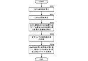
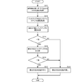
- Functional block diagram of the attitude angle calculation device Flowchart of a posture angle calculation method according to the first embodiment of the present invention.
- Functional block diagram of the attitude angle calculation device Flowchart of a sensor error calculation method according to the second embodiment of the present invention.
- Functional block diagram of an attitude angle calculation device Flowchart of attitude angle calculation method according to the third embodiment of the present invention.
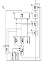
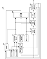
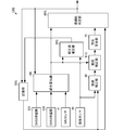
- Functional block diagram of the posture angle calculation device according to the fourth embodiment of the present invention The flowchart of the process relevant to the reliability determination in the attitude
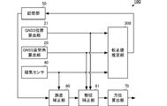
- FIG. 1 is a functional block diagram of an attitude angle calculation apparatus according to the first embodiment of the present invention.
- the attitude angle calculation device 10 is mounted on a moving body such as a ship.
- the x-axis direction of the magnetic sensor 40 (same as the x-axis direction of GNSS geomagnetism described later) is the front-rear direction of the moving body (the leading direction from the center of the moving body is the + direction).
- the moving body is mounted such that the y-axis direction (the same as the y-axis direction of GNSS geomagnetism described later) is the left-right direction of the moving body (the direction facing the right side from the center of the moving body is the + direction).
- the x-axis direction corresponds to the “first direction” of the present invention
- the y-axis direction corresponds to the “second direction” of the present invention.
- the moving body is not limited to a ship that travels on the water, such as a ship, but may also move on the water, on land, and in the air.
- the present invention is more effective for a moving body such as a ship that cannot be turned quickly.
- the attitude angle calculation device 10 includes a GNSS attitude angle calculation unit 20, a calibration value estimation unit 30, a magnetic sensor 40, a storage unit 50, an error correction unit 60, and an orientation calculation unit 70.
- the calibration value estimation unit 30 includes a GNSS geomagnetism calculation unit 301, an error estimation unit 302, and a calibration value calculation unit 303.
- the GNSS attitude angle calculation unit 20, the GNSS geomagnetism calculation unit 301, and the error estimation unit 302 correspond to the sensor error calculation device 1.
- the GNSS attitude angle calculator 20, the GNSS geomagnetism calculator 301 and the error estimator 302 of the calibration value estimator 30 are executed by the hardware processor 11 included in the sensor error calculator 1.
- the calibration value calculation unit 303 may also be executed by the hardware processor 11.
- GNSS is an abbreviation for Global Navigation Satellite Systems, and indicates a satellite positioning system such as GPS (Global Positioning System), GLONASS, Galileo, and the like.
- a GNSS receiver (not shown) is connected to the GNSS attitude angle calculator 20, and a GNSS antenna (not shown) is connected to the GNSS receiver.
- the plurality of GNSS antennas are fixed in a predetermined positional relationship with respect to the moving body.
- the plurality of GNSS antennas receive positioning signals and output them to the GNSS receiver.
- the GNSS reception unit tracks the positioning signal and outputs a measurement value obtained by tracking including the carrier phase to the GNSS attitude angle calculation unit 20. Further, the GNSS receiver demodulates the navigation message from the positioning signal and outputs it to the GNSS attitude angle calculator 20 in tracking the positioning signal.
- the GNSS attitude angle calculation unit 20 calculates an attitude angle (GNSS attitude angle) by a known method using a measurement value obtained by tracking a positioning signal and a navigation message.
- the GNSS attitude angle is composed of three components: a roll angle ⁇ GNSS , a pitch angle ⁇ GNSS , and an azimuth angle (yaw angle) ⁇ GNSS .
- the GNSS attitude angle calculation unit 20 outputs the GNSS attitude angle to the calibration value estimation unit 30.
- the magnetic sensor 40 is fixed to the moving body.
- the magnetic sensor 40 detects external magnetism including geomagnetism, and outputs a magnetic detection value [m MAGx , m MAGy ] that is a component of two orthogonal axes to the calibration value estimation unit 30 and the error correction unit 60.
- the calibration value estimation unit 30 uses the GNSS attitude angles [ ⁇ GNSS , ⁇ GNSS , ⁇ GNSS ] and the magnetic detection values [m MAGx , m MAGy ] to detect the magnetic detection values [m MAGx , m MAGy of the magnetic sensor 40. ] Is estimated for each of the sensitivity error, misalignment error, and bias error included in the.
- the calibration value estimation unit 30 estimates a calibration value using at least three GNSS attitude angles and magnetic detection values. In these three times, the posture of the moving body is different.
- the calibration value estimation unit 30 includes a GNSS geomagnetism calculation unit 301, an error estimation unit 302, and a calibration value calculation unit 303.
- the calibration value estimation unit 30 estimates the calibration value by executing the following process.
- the GNSS geomagnetism calculation unit 301 of the calibration value estimation unit 30 uses the following (Equation 1) and (Equation 2) from the GNSS attitude angle [ ⁇ GNSS , ⁇ GNSS , ⁇ GNSS ] to the GNSS geomagnetism [ m GNSSx , m GNSSy ] is calculated.
- the error calculation unit 302 of the calibration value estimation unit 30 estimates each error (sensitivity error, misalignment error, and bias error) of the magnetic sensor using the following (Equation 3).
- [ ⁇ xx , ⁇ yy ] is a sensitivity error of the magnetic sensor 40 in the x-axis direction and the y-axis direction.
- [ ⁇ xy , ⁇ yx ] is a misalignment error of the magnetic sensor 40 in the x-axis direction and the y-axis direction.
- [ ⁇ m x , ⁇ m y ] is a bias error of the magnetic sensor 40 in the x-axis direction and the y-axis direction.
- the calibration value calculation unit 303 of the calibration value estimation unit 30 uses a sensitivity / misalignment calibration matrix MM for the magnetic sensor 40 from the sensitivity error and the misalignment error estimated by (Equation 3) using the following (Equation 4). To calculate.
- the calibration value calculation unit 303 of the calibration value estimation unit 30 includes a conversion coefficient for setting the magnitude to “1” and a conversion coefficient for correcting the magnetic deviation, so that the sensitivity / misalignment calibration matrix MM is included. Is set.
- the calibration value estimation unit 30 outputs the sensitivity / misalignment calibration matrix MM and the bias error [ ⁇ m x , ⁇ m y ] as calibration values to the storage unit 50.
- the storage unit 50 stores calibration values, that is, a sensitivity / misalignment calibration matrix MM and a bias error [ ⁇ m x , ⁇ m y ]. Each time a new calibration value is input, the storage unit 50 overwrites and stores the stored calibration value with the new calibration value.
- the error correction unit 60 acquires a calibration value from the storage unit 50.
- the error correction unit 60 corrects the magnetic detection value [m MAGx , m MAGy ] of the magnetic sensor 40 with the calibration value using the following (Equation 5).
- [M b MAGx, m b MAGy ] is a magnetic detection value after error correction.
- Error correction unit 60 outputs the magnetic detection value after error correction [m b MAGx, m b MAGy ] to the orientation calculation unit 70.
- the orientation calculation unit 70 magnetic detection value after error correction [m b MAGx, m b MAGy ] is used to calculate the azimuth [psi MAG in a known manner.
- the azimuth calculation unit 70 moves the x-axis component m b MAGx and the y-axis component m b MAGy of the detected value after error correction and the x-axis and y-axis of the magnetic sensor 40.
- the direction ⁇ MAG is calculated using the relationship with the tip direction of the body (for example, the bow direction of the ship).
- the direction ⁇ MAG is calculated using the following (formula 6).
- the geomagnetism is calculated from the GNSS attitude angle using the GNSS positioning signal that is not affected by the sensitivity error, the misalignment error, and the bias error, and the geomagnetism and magnetism based on the GNSS attitude angle are calculated.
- the sensitivity error, misalignment error, and bias error of the magnetic sensor 40 are estimated from the magnetic detection value of the sensor 40. Therefore, the sensitivity error, misalignment error, and bias error of the magnetic sensor 40, that is, all error components constituting the error of the magnetic sensor 40 can be estimated with high accuracy.
- the error can be calculated based on the GNSS attitude angle obtained by the three observations and the magnetic detection value of the magnetic sensor, the error included in the magnetic detection value of the magnetic sensor 40 can be calculated quickly.
- the direction can be calculated with high accuracy by using the magnetic detection value corrected with the error calculated with high accuracy in this way.
- the attitude angle calculation device 10 described above executes each process with individual functional blocks, as shown in FIG.
- the above-described error calculation and azimuth calculation processes may be programmed and stored in a storage medium, and an information processing apparatus such as a computer may read the program from the storage medium and execute it.
- the process shown in FIG. FIG. 2 is a flowchart of the attitude angle calculation method according to the first embodiment of the present invention.
- the information processing apparatus calculates a GNSS attitude angle using a measurement value obtained by tracking a GNSS positioning signal (S101).
- the information processing apparatus calculates GNSS geomagnetism from the GNSS attitude angle using the above-described (Expression 1) and (Expression 2) (S102).
- the information processing apparatus acquires a magnetic detection value from the magnetic sensor (S103).
- the information processing apparatus estimates the calibration value (sensitivity / misalignment calibration matrix and bias error) of the magnetic sensor using the GNSS geomagnetism, the magnetic detection value, and (Equation 3) for three times (S104).
- the processing so far corresponds to the processing of the “sensor error calculation method” of the present invention.
- the information processing apparatus corrects the error of the magnetic detection value using the calibration value and (Equation 5) (S105).
- the information processing apparatus calculates the azimuth using the magnetic detection value after error correction (S106).
- FIG. 3 is a functional block diagram of an attitude angle calculation apparatus according to the second embodiment of the present invention.
- the posture angle calculation device 10A according to the present embodiment is obtained by adding a GNSS position calculation unit 21 to the posture angle calculation device 10 according to the first embodiment, and the process of the calibration value estimation unit 30A is calibrated. This is different from the value estimation unit 30.
- the GNSS position calculation unit 21 is connected to a GNSS reception unit (not shown) to which the GNSS attitude angle calculation unit 20 is connected.
- the GNSS position calculation unit 21 is input with a pseudo code distance, which is a measurement value obtained by tracking a positioning signal, and a navigation message.
- the GNSS position calculation unit 21 calculates the GNSS position by a known method using the code pseudorange and the position information of the positioning satellite included in the navigation message.
- the GNSS position calculation unit 21 outputs the GNSS position to the calibration value estimation unit 30A.
- the calibration value estimation unit 30A calculates the latitude Lat from the GNSS position.
- the calibration value estimation unit 30A uses the following (Expression 7) and (Expression 8) to calculate the GNSS geomagnetism [m GNSSx , m GNSSy ] from the GNSS attitude angle [ ⁇ GNSS , ⁇ GNSS , ⁇ GNSS ]. Is calculated.
- fx (Lat, ⁇ GNSS ) is a fluctuation correction term for the GNSS geomagnetism in the x-axis direction, and is a function value determined by the latitude Lat and the pitch angle ⁇ GNSS .
- fy (Lat, ⁇ GNSS , ⁇ GNSS ) is a fluctuation correction term for the GNSS geomagnetism in the y-axis direction, and is a function value determined by the latitude Lat, the pitch angle ⁇ GNSS, and the roll angle ⁇ GNSS .
- the calibration value estimation unit 30A applies the GNSS geomagnetism [m GNSSx , m GNSSy ] calculated from (Equation 7) and (Equation 8) to (Equation 3), thereby obtaining a sensitivity error [ ⁇ xx , ⁇ yy ], A misalignment error [ ⁇ xy , ⁇ yx ] and a bias error [ ⁇ m x , ⁇ m y ] are estimated, and a calibration value is calculated.
- sensitivity error [ ⁇ xx, ⁇ yy], misalignment error [ ⁇ xy, ⁇ yx], and the bias error [ ⁇ m x, ⁇ m y] moving body included in the (magnetic sensor) Can suppress the effects of shaking.
- sensitivity error [ ⁇ xx, ⁇ yy], misalignment error [ ⁇ xy, ⁇ yx], and the bias error [ ⁇ m x, ⁇ m y] can be estimated with higher accuracy, calculating a highly accurate calibration values can do. Then, by using this highly accurate calibration value, the azimuth can be calculated with high accuracy.
- the attitude angle calculation device 10A described above executes each process with individual functional blocks as shown in FIG.
- the above-described error calculation and azimuth calculation processes may be programmed and stored in a storage medium, and an information processing apparatus such as a computer may read the program from the storage medium and execute it.
- the process shown in FIG. FIG. 4 is a flowchart of a sensor error calculation method according to the second embodiment of the present invention.
- the information processing apparatus calculates a GNSS attitude angle using a measurement value obtained by tracking a GNSS positioning signal (S101).
- the information processing apparatus calculates the GNSS position using the measurement value obtained by tracking the GNSS positioning signal (S111).
- the information processing apparatus calculates GNSS geomagnetism with fluctuation correction from the GNSS attitude angle using (Expression 7) and (Expression 8) described above (S112).
- the information processing apparatus acquires a detection value (sensor value) from the magnetic sensor (S103).
- the information processing apparatus uses the GNSS geomagnetism, sensor value, and (Equation 3) calculated by (Equation 7) and (Equation 8) to calculate the calibration value (sensitivity / misalignment calibration matrix and bias) of the magnetic sensor. Error) is estimated (S104).
- the azimuth calculation process is the same as steps S105 and S106 in the first embodiment shown in FIG.
- FIG. 5 is a functional block diagram of an attitude angle calculation apparatus according to the third embodiment of the present invention.
- the posture angle calculation device 10B according to the present embodiment is obtained by adding a fluctuation correction unit 61 to the posture angle calculation device 10A according to the second embodiment.
- the calibration value estimation unit 30B is the same as the calibration value estimation unit 30A according to the second embodiment.
- the GNSS posture angle is input from the GNSS posture angle calculation unit 20 to the fluctuation correction unit 61.
- the GNSS position is input from the GNSS position calculation unit 21 to the fluctuation correction unit 61.
- the upset correcting unit 61, magnetic detection value after the error correction from the error correcting unit 60 [m b MAGx, m b MAGy] is input.
- the fluctuation correcting unit 61 calculates the latitude Lat from the GNSS position.
- the motion correction unit 61 uses the following (Equation 9), the GNSS attitude angle [ ⁇ GNSS , ⁇ GNSS , ⁇ GNSS ], and the latitude Lat to detect the magnetic detection value [m b MAGx , m b after error correction ].
- MAGy ] is corrected for shaking.
- [M h MAGx, m h MAGy ] is the detection value after upset corrected.
- the magnetic detection value [m h after the shake correction is calculated using the following (Equation 10).
- MAGx , m h MAGy may be calculated.
- the shake correction unit 61 outputs the magnetic detection value [m h MAGx , m h MAGy ] after the shake correction to the azimuth calculation unit 70.
- the azimuth calculation unit 70 uses the magnetic detection values [m h MAGx , m h MAGy ] after shake correction to calculate the azimuth by the same method as in the first embodiment.
- the attitude angle calculation device 10B described above executes each process with individual function blocks as shown in FIG.
- the above-described error calculation and azimuth calculation processes may be programmed and stored in a storage medium, and an information processing apparatus such as a computer may read the program from the storage medium and execute it.
- the process shown in FIG. FIG. 6 is a flowchart of the attitude angle calculation method according to the third embodiment of the present invention.
- the information processing apparatus calculates a GNSS attitude angle using a measurement value obtained by tracking a GNSS positioning signal (S101).
- the information processing apparatus calculates the GNSS position using the measurement value obtained by tracking the GNSS positioning signal (S111).
- the information processing apparatus calculates the GNSS geomagnetism with fluctuation correction from the latitude based on the GNSS position and the GNSS attitude angle using (Expression 7) and (Expression 8) described above (S112).
- the information processing apparatus acquires a detection value (sensor value) from the magnetic sensor (S103).
- the information processing apparatus uses the GNSS geomagnetism, sensor value, and (Equation 3) calculated by (Equation 7) and (Equation 8) to calculate the calibration value (sensitivity / misalignment calibration matrix and bias) of the magnetic sensor. Error) is estimated (S104).
- the information processing apparatus corrects the error of the sensor value using the calibration value and (Equation 5) (S105).
- the information processing apparatus performs shake correction on the sensor value after error correction using the GNSS attitude angle, latitude, and (Equation 10) (S121).
- the information processing apparatus calculates an azimuth using the sensor value after shake correction (S122).
- FIG. 7 is a functional block diagram of an attitude angle calculation apparatus according to the fourth embodiment of the present invention.
- the posture angle calculation device 10C according to the present embodiment is obtained by adding an integer value bias determination unit 22 and a reliability determination unit 80 to the posture angle calculation device 10B according to the third embodiment.
- the attitude angle calculation device 10C includes GNSS reception units 231 and 232 that are not illustrated in the attitude angle calculation devices 10, 10A, and 10B of the above-described embodiments.
- the calibration value estimation unit 30C is the same as the calibration value estimation unit 30B according to the third embodiment.
- the GNSS receivers 231 and 232 track positioning signals received by the GNSS antennas connected thereto.
- the GNSS receivers 231 and 232 output the carrier phase and code pseudorange to the GNSS position calculator 21.
- the GNSS receiving units 231 and 232 output the carrier wave phase to the integer value bias determining unit 22.
- the integer value bias determination unit 22 uses the azimuth ⁇ MAG output from the reliability determination unit 80, which will be described later, to calculate the difference in carrier phase of the positioning signals received by the GNSS reception units 231 and 232 (single phase difference between antennas). Determine integer value bias. Thus, the integer value bias can be easily determined by using the orientation.
- the integer value bias determination unit 22 outputs the integer value bias to the GNSS attitude angle calculation unit 20 together with the carrier phase.
- the GNSS attitude angle calculation unit 20 calculates the GNSS attitude angle using the integer value bias and the carrier wave phase.
- the integer value bias determination unit 22 determines the integer value bias by a known GNSS if the direction ⁇ MAG is not input from the reliability determination unit 80 as described later (if the direction ⁇ MAG is not reliable). Execute.
- the storage unit 50C stores a GNSS position and a GNSS attitude angle along with the calibration value.
- the storage unit 50C only needs to store at least the azimuth ⁇ GNSS of the GNSS attitude angle along with the calibration value.
- the orientation stored in the storage unit 50C is the backup orientation in the present embodiment.
- the reliability determination unit 80 acquires a backup orientation from the storage unit 50C. If the reliability determination unit 80 determines that the azimuth ⁇ MAG calculated by the azimuth calculation unit 70 matches the backup azimuth (azimuth ⁇ GNSS of the GNSS attitude angle), the azimuth ⁇ MAG and the backup azimuth are reliable. Is determined. On the other hand, if the reliability determination unit 80 determines that the azimuth ⁇ MAG calculated by the azimuth calculation unit 70 does not match the backup azimuth (azimuth ⁇ GNSS of the GNSS attitude angle), the azimuth ⁇ MAG and the backup azimuth are reliable. Judge that there is no.
- the reliability determination unit 80 calculates a difference ⁇ between the azimuth ⁇ MAG and the backup azimuth (GNSS attitude angle azimuth ⁇ GNSS ), and if the difference ⁇ is equal to or less than the threshold ⁇ TH , It is determined that ⁇ MAG and the backup orientation (GNSS attitude angle orientation ⁇ GNSS ) match. On the other hand, if the difference ⁇ is larger than the threshold value ⁇ TH , the reliability determination unit 80 determines that the azimuth ⁇ MAG and the backup azimuth (GNSS attitude angle azimuth ⁇ GNSS ) do not match.
- the threshold ⁇ TH may be about 15 ° to 30 °.
- Reliability determining unit 80 determines that there reliability, and outputs the azimuth [psi MAG outside and integer ambiguity determination section 22. On the other hand, the reliability determination unit 80 determines that unreliable and does not output the azimuth [psi MAG. At this time, the reliability determination unit 80 may notify the outside of the presence or absence of reliability via a notification unit (a display unit, a sound emitting unit, etc., not shown).
- a notification unit a display unit, a sound emitting unit, etc., not shown.
- FIG. 8 is a flowchart of processing related to reliability determination in the posture angle calculation method according to the fourth embodiment of the present invention.
- the orientation calculation unit 70 calculates the azimuth [psi MAG using the sensor values after shaking correction (S201).
- Reliability determining unit 80 determines the reliability of the azimuth ⁇ MAG (S202).
- Reliability determining unit 80 determines that there is reliable (S203: YES), along with utilizing the orientation [psi MAG to determine the integer ambiguity (S204), and outputs the azimuth [psi MAG outside (S205).
- Reliability determining unit 80 determines that unreliable (S203: NO), does not output the azimuth ⁇ MAG (S206).
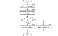
- FIG. 9 is a flowchart of specific processing for reliability determination in the posture angle calculation processing according to the fourth embodiment of the present invention.
- the reliability determination unit 80 acquires a backup orientation from the storage unit 50C (S302).
- the reliability determination unit 80 compares the direction ⁇ MAG calculated by the direction calculation unit 70 with the backup direction (S303).
- Reliability determination unit 80 determines that there is reliability and azimuth [psi MAG and backup azimuth (S305).
- the state where the azimuth ⁇ MAG and the backup azimuth coincide with each other indicates that the difference ⁇ between the azimuth ⁇ MAG and the backup azimuth is equal to or less than the threshold ⁇ TH .
- the reliability determination unit 80 determines that the azimuth ⁇ MAG and the backup azimuth are not reliable (S306).
- FIG. 10 is a functional block diagram of an attitude angle calculation apparatus according to the fifth embodiment of the present invention.
- the posture angle calculation device 10D according to the present embodiment is different from the posture angle calculation device 10C according to the fourth embodiment in the storage unit 50D and the reliability determination unit 80D.
- the calibration value estimation unit 30D is the same as the calibration value estimation unit 30C according to the fourth embodiment.
- Storage unit 50D together with calibration values, and stores the orientation [psi MAG output from the reliability determination unit 80D as a backup bearing.
- Reliability determining unit 80D compares the azimuth [psi MAG and backup orientation calculated by the orientation calculation unit 70, and determines reliability.
- backup bearing used is calculated in the past in the storage unit 50D stored azimuth [psi MAG.
- the reliability of the azimuth can be determined even in an environment where the GNSS attitude angle cannot be calculated.
- FIG. 11 is a functional block diagram of an attitude angle calculation apparatus according to the sixth embodiment of the present invention.
- the posture angle calculation device 10E according to the present embodiment is different from the posture angle calculation device 10D according to the fifth embodiment in the reliability determination unit 80E.
- the calibration value estimation unit 30E is the same as the calibration value estimation unit 30D according to the fifth embodiment, and the storage unit 50E further uses the GNSS position as a backup position with respect to the storage unit 50D according to the fifth embodiment. It has a function to memorize.
- the reliability determination unit 80E determines reliability by executing the following process.
- FIG. 12 is a flowchart of reliability determination of the posture angle calculation process according to the sixth embodiment of the present invention.
- the reliability determination unit 80E acquires the azimuth ⁇ MAG calculated by the azimuth calculation unit 70 and the GNSS position calculated by the GNSS position calculation unit 21 (S311). The reliability determination unit 80E acquires the backup direction and the backup position from the storage unit 50E (S312).
- the reliability determination unit 80E compares the GNSS position with the backup position (S313). If the GNSS position matches the backup position (S314: YES), the reliability determination unit 80E proceeds to the process of step S315. For example, the reliability determination unit 80E determines that the GNSS position and the backup position match if the difference between the GNSS position and the backup position (coordinate difference in each axis direction) is within a threshold value. Reliability determination unit 80E, unless the GNSS position and the backup position match (S314: NO), the calculated azimuth [psi MAG determines that unreliable (S318). For example, the reliability determination unit 80E determines that the GNSS position and the backup position do not match if the difference between the GNSS position and the backup position (difference in coordinates in each axis direction) is greater than a threshold value.
- the reliability determination unit 80E compares the direction ⁇ MAG with the backup direction (S315). When the azimuth ⁇ MAG matches the backup azimuth (S316: YES), the reliability determination unit 80E determines that the calculated azimuth ⁇ MAG has reliability (S317). If the azimuth ⁇ MAG does not match the backup azimuth (S316: NO), the reliability determination unit 80E determines that the calculated azimuth ⁇ MAG is not reliable (S318). The determination as to whether or not the azimuth ⁇ MAG and the backup azimuth coincide may be performed using the same method as in the above-described embodiment.
- the reliability of the azimuth [psi MAG.
- the GNSS position (corresponding to the current position) and the backup position (corresponding to the past position) are greatly different, the directions are naturally different unless they are on substantially the same longitude. Therefore, in such a case, the reliability of the azimuth cannot be said to be high without comparing the azimuths, and the reliability of the azimuth can be easily determined.
- FIG. 13 is a functional block diagram of an attitude angle calculation apparatus according to the seventh embodiment of the present invention.
- the posture angle calculation device 10F according to the present embodiment is different from the posture angle calculation device 10E according to the sixth embodiment in the processing that uses the azimuth to calculate the integer value bias.
- the calibration value estimation unit 30F and the storage unit 50F are the same as the calibration value estimation unit 30E and the storage unit 50E of the posture angle calculation device 10E according to the sixth embodiment.
- Reliability determining unit 80F outputs the azimuth [psi MAG, and outputs whether the reliability of the azimuth [psi MAG. Integer ambiguity determination unit 22F is, if there is reliable orientation [psi MAG, utilizing orientation [psi MAG to determine the integer ambiguity. If the azimuth ⁇ MAG is not reliable, the integer value bias determination unit 22F executes an integer value bias determination process using a known GNSS.
- the integer value bias is determined using only the reliable azimuth, so that the integer value bias can be determined accurately and quickly.
- FIG. 14 is a functional block diagram of a posture angle calculation apparatus according to the eighth embodiment of the present invention.
- the posture angle calculation device 10G according to the present embodiment differs from the posture angle calculation device 10C according to the fourth embodiment of the present invention in that an integrated posture angle is used instead of the GNSS posture angle.
- the basic processing of the posture angle calculation device 10G is the same as that of the posture angle calculation device 10C according to the fourth embodiment of the present invention, and different points will be described in detail below.
- the integrated attitude angle is an attitude angle calculated using a measurement value such as a carrier phase obtained from a positioning signal and an IMU sensor measurement value measured by the IMU sensor 41.
- Attitude angle calculation device 10G includes integrated calculation unit 100, GNSS reception units 231, 232, calibration value estimation unit 30G, magnetic sensor 40, IMU sensor 41, storage unit 50G, error correction unit 60, fluctuation correction unit 61G, and direction calculation unit. 70 and a reliability determination unit 80G.
- the GNSS receivers 231 and 232 track the positioning signals, acquire measurement values obtained by tracking the carrier wave phase and the like, and output them to the integrated calculation unit 100.
- the IMU sensor 41 includes at least one of inertial sensors such as an acceleration sensor and an angular velocity sensor.
- the IMU sensor 41 outputs the measured sensor value (IMU sensor value) to the integrated calculation unit 100.
- the integrated calculation unit 100 calculates the integrated posture angle by a known method using the tracking measurement value and the IMU sensor value.
- the integrated calculation unit 100 outputs the integrated posture angle to the calibration value estimation unit 30G and the reliability determination unit 80G.
- the integrated calculation unit 100 calculates an integrated position by a known method using a measurement value obtained by tracking.
- the integration calculation unit 100 outputs the integration position to the storage unit 50G and the reliability determination unit 80G.
- the storage unit 50G stores the integrated position as a backup position.
- the magnetic sensor 40 outputs the magnetic detection value to the calibration value estimation unit 30G and the error correction unit 60.
- the calibration value estimation unit 30G calculates the geomagnetism from the integrated attitude angle, estimates the sensitivity error, the misalignment error, and the bias error of the magnetic sensor 40 using the geomagnetism based on the integrated attitude angle and the detected value of the magnetic sensor, and performs calibration. Calculate the value.
- the calibration value estimation unit 30G outputs the calibration value to the storage unit 50G.
- the error correction unit 60 acquires the calibration value from the storage unit 50G, and corrects the detection value of the magnetic sensor using the calibration value.
- the shake correction unit 61G performs shake correction on the detected value of the magnetic sensor after the error correction using the integrated posture angle.
- the azimuth calculation unit 70 calculates the azimuth using the detected value of the magnetic sensor after the shake correction.
- the reliability determination unit 80G performs reliability determination of the azimuth calculated using the detection value of the magnetic sensor, using the backup azimuth acquired from the storage unit 50G.
- an integrated position may be used as in the case of using the GNSS position shown in the above-described embodiment. Furthermore, an integration speed based on the integration position may be used. If there is azimuth reliability, the reliability determination unit 80G outputs the azimuth to the outside and also outputs it to the storage unit 50G and the integrated calculation unit 100.
- the storage unit 50G stores this orientation as a backup orientation.
- the integrated calculation unit 100 determines an integer value bias using this orientation.
- FIG. 15 is a flowchart of reliability determination in the attitude angle calculation method according to the eighth embodiment of the present invention.
- the reliability determination unit 80G acquires the integration position calculated by the integration calculation unit 100, the backup position and the backup direction stored in the storage unit 50G (S321).
- the reliability determination unit 80G compares the integrated position with the backup position (S322). If the integrated position matches the backup position (S323: YES), the reliability determination unit 80G proceeds to the process of step S324. Reliability determining unit 80G, unless the integration position and the backup position match (S323: NO), the calculated azimuth [psi MAG determines that unreliable (S329).
- the reliability determination unit 80G compares the direction ⁇ MAG with the backup direction (S324). Reliability determining unit 80G, if match the azimuth [psi MAG and backup orientation (S325: YES), the process proceeds to step S326. If the azimuth ⁇ MAG does not match the backup azimuth (S325: NO), the reliability determining unit 80G determines that the calculated azimuth ⁇ MAG is not reliable (S329).
- the reliability determination unit 80G calculates a GNSS speed from a plurality of GNSS positions and performs a berthing determination based on the GNSS speed (S326).
- the reliability determination unit 80G determines that the berth is not anchored if the GNSS speed is approximately “0”, and determines that the anchor is not anchored if the GNSS speed is not approximately “0”.
- the speed may be acquired by other methods. For example, an integrated value of acceleration or the like can be used.
- Reliability determining unit 80G if at anchor (S327: YES), the calculated azimuth [psi MAG determines that there is reliability (S328). Reliability determining unit 80G is, if the berth (S327: NO), the calculated azimuth [psi MAG determines that unreliable (S318).
- the integrated posture angle and the integrated position shown in the present embodiment can be used by replacing them with the GNSS posture angle and the GNSS position in the other embodiments.
- FIG. 16 is a functional block diagram of an attitude angle calculation device according to the ninth embodiment of the present invention.
- the posture angle calculation device 10H performs only reliability determination without estimating the calibration values shown in the above-described embodiments.
- the attitude angle calculation device 10H uses the orientation by the magnetic sensor as the integrated attitude angle.
- the attitude angle calculation device 10H includes an integrated calculation unit 100H, GNSS reception units 231, 232, a magnetic sensor 40, an IMU sensor 41, a storage unit 50H, an orientation calculation unit 70, and a reliability determination unit 80H.
- the GNSS receivers 231 and 232 track the positioning signals, acquire measurement values obtained by tracking the carrier wave phase and the like, and output them to the integrated calculation unit 100H.
- the GNSS receiving unit 232 outputs the measurement value obtained by tracking to the reliability determining unit 80G.
- the IMU sensor 41 includes an acceleration sensor 411 and an angular velocity sensor 412.
- the acceleration sensor 411 and the angular velocity sensor 412 output the measured sensor values (acceleration sensor value and angular velocity sensor value) to the integrated calculation unit 100.
- the acceleration sensor 411 outputs the acceleration sensor value to the reliability determination unit 80H.
- the integrated calculation unit 100H calculates the integrated posture angle by a known method using the measurement value by tracking, the acceleration sensor value and the angular velocity sensor value, and the azimuth by the detection value of the magnetic sensor.
- the integration calculation unit 100H calculates the integration position by a known method using the measurement value obtained by tracking.
- the integrated calculation unit 100H outputs the integrated posture angle and the integrated position to the storage unit 50H.
- the storage unit 50H stores the integrated position and the integrated attitude angle as a backup position and a backup attitude angle.
- the magnetic sensor 40 outputs the detection value of the magnetic sensor to the azimuth calculation unit 70.
- the azimuth calculation unit 70 calculates the azimuth using the detection value of the magnetic sensor.
- the reliability determination unit 80H performs the reliability determination of the azimuth calculated using the detection value of the magnetic sensor, using the backup azimuth acquired from the storage unit 50H. At this time, the reliability determination unit 80H may calculate a GNSS position using a measurement value obtained by tracking obtained from the GNSS reception unit 232, and may use this GNSS position for determination of reliability. As a method for determining reliability, the method described in the above embodiment may be used. If there is reliability of the calculated direction, reliability determination unit 80H outputs the direction to integrated calculation unit 100H. The integrated calculation unit 100H uses the azimuth based on the magnetic detection value as an initial azimuth for determining an integer value bias. As a result, the integrated posture angle can be calculated more quickly.
Landscapes
- Engineering & Computer Science (AREA)
- Radar, Positioning & Navigation (AREA)
- Remote Sensing (AREA)
- Physics & Mathematics (AREA)
- General Physics & Mathematics (AREA)
- Computer Networks & Wireless Communication (AREA)
- Automation & Control Theory (AREA)
- Navigation (AREA)
Abstract
【課題】磁気センサの誤差を高精度に且つ素早く算出する。 【解決手段】センサ誤差算出装置1は、GNSS姿勢角算出部20、GNSS地磁気算出部301、および、誤差推定部302を備える。GNSS姿勢角算出部20は、GNSSの測位信号からGNSS姿勢角を算出する。GNSS地磁気算出部301は、GNSS姿勢角からGNSS地磁気を算出する。誤差推定部302は、磁気センサによる磁気検出値とGNSS地磁気とを用いて、磁気センサの感度誤差、ミスアライメント誤差、および、バイアス誤差を推定する。
Description
本発明は、船舶等の移動体に設置された磁気センサの誤差を算出するセンサ誤差算出装置およびセンサ誤差算出方法と、磁気センサの磁気検出値を用いて船首方位等の方位を算出する姿勢角算出装置および姿勢角算出方法に関する。
磁気センサで地磁気を検出して、移動体の方位を算出する方位算出装置が各種実用化されている。磁気センサは、直交する二軸または三軸の磁界強度を電圧等によって検出する。方位算出装置は、この二軸もしくは三軸の検出値の関係から方位を算出する。
一般に汎用の磁気センサは、磁気検出値に誤差を含んでいることが知られている。したがって、方位算出装置は、この誤差を補正することによって、算出する方位の精度を向上させようとしている。
特許文献1では、磁気センサが装着された船舶を1周旋回させて、複数の磁気検出値を取得し、この複数の磁気検出値の軌跡から、磁気検出値に含まれる外乱磁場による誤差を算出している。
特許文献2では、外部からの標準地磁気データと、衛星信号を用いて算出した船首方位、位置、および、この位置に対応する地磁気データとを用いて、各方位の残留磁気値(磁気バイアス)を算出している。
特許文献3では、2回分のGPS方位と、磁気センサの出力値から算出される磁気方位とを用いて、磁気センサの感度誤差とバイアス誤差を算出している。
しかしながら、特許文献1に記載の方法では、磁気センサが装着された船舶(移動体)を1周旋回させなければならず、磁気センサの誤差の算出に時間を要する。
また、特許文献2,3に記載の方法では、誤差の一部しか算出されていないので、誤差を高精度に算出することができない。
したがって、本発明の目的は、磁気センサの誤差を高精度に且つ素早く算出することができるセンサ誤差算出装置、センサ誤差算出方法、このセンサ誤差を用いて高精度に方位を算出する姿勢角算出装置および姿勢角算出方法を提供することにある。
この発明のセンサ誤差算出装置は、GNSS姿勢角算出部、GNSS地磁気算出部、および、誤差推定部を備える。GNSS姿勢角算出部は、GNSSの測位信号からGNSS姿勢角を算出する。GNSS地磁気算出部は、GNSS姿勢角からGNSS地磁気を算出する。誤差推定部は、磁気センサによる磁気検出値とGNSS地磁気とを用いて、磁気センサの感度誤差、ミスアライメント誤差、および、バイアス誤差を推定する。
この構成では、感度誤差、ミスアライメント誤差、および、バイアス誤差の無いGNSS姿勢角を用いてGNSS地磁気が算出される。したがって、このGNSS地磁気を用いて誤差を推定することによって、磁気センサの各誤差(較正値)が高精度に推定される。
また、この発明の姿勢角算出装置は、上述のいずれかに記載のセンサ誤差算出装置の各構成部、誤差補正部、および、方位算出部を備える。誤差補正部は、磁気センサの感度誤差、ミスアライメント誤差、および、バイアス誤差を用いて、磁気検出値を補正する。方位算出部は、誤差補正後の磁気検出値を用いて方位を算出する。
この構成では、高精度に推定された誤差によって、磁気センサの磁気検出値の誤差が補正され、方位が高精度に算出される。
この発明によれば、磁気センサの誤差を高精度に且つ素早く算出することができる。したがって、この算出誤差を用いて磁気センサの誤差を補正することで、高精度な方位を素早く算出することができる。
本発明の第1の実施形態に係るセンサ誤差算出装置およびセンサ誤差算出方法と、姿勢角算出装置および姿勢角算出方法について、図を参照して説明する。図1は、本発明の第1の実施形態に係る姿勢角算出装置の機能ブロック図である。
姿勢角算出装置10は、船舶等の移動体に装着されている。姿勢角算出装置10は、磁気センサ40のx軸方向(後述するGNSS地磁気のx軸方向と同じ)が移動体の前後方向(移動体の中心から先頭方向が+方向)となり、磁気センサ40のy軸方向(後述するGNSS地磁気のy軸方向と同じ)が移動体の左右方向(移動体の中心から右側を向く方向が+方向)となるように、移動体に装着されている。x軸方向が本発明の「第1方向」に対応し、y軸方向が本発明の「第2方向」に対応する。なお、移動体は、船舶等の水上を航行するものだけでなく、水中、陸上、空中を移動するものであってもよい。ただし、素早い旋回が容易でない船舶等の移動体に対して、本願発明はより有効である。
姿勢角算出装置10は、GNSS姿勢角算出部20、較正値推定部30、磁気センサ40、記憶部50、誤差補正部60、および、方位算出部70を備える。較正値推定部30は、GNSS地磁気算出部301、誤差推定部302、および、較正値算出部303を備える。GNSS姿勢角算出部20、GNSS地磁気算出部301、および誤差推定部302が、センサ誤差算出装置1に対応する。GNSS姿勢角算出部20と較正値推定部30のGNSS地磁気算出部301および誤差推定部302とは、センサ誤差算出装置1が備えるハードウェアプロセッサ11によって実行される。なお、較正値算出部303もハードウェアプロセッサ11によって実行されていてもよい。GNSSは、Grobal Navigation Satellite Systemsの略語であり、GPS(Grobal Positioning System)、GLONASS、Galileo等の衛星測位システムを示す。
GNSS姿勢角算出部20には、GNSS受信部(図示せず)が接続されており、GNSS受信部にはGNSSアンテナ(図示せず)が接続されている。GNSS受信部およびGNSSアンテナは、複数である。複数のGNSSアンテナは、移動体に対して所定の位置関係で固定されている。複数のGNSSアンテナは、測位信号を受信してGNSS受信部に出力する。GNSS受信部は、測位信号を追尾して、搬送波位相を含む追尾による計測値を、GNSS姿勢角算出部20に出力する。また、GNSS受信部は、測位信号の追尾において、測位信号から航法メッセージを復調して、GNSS姿勢角算出部20に出力する。
GNSS姿勢角算出部20は、測位信号の追尾による計測値および航法メッセージを用いて、既知の方法によって姿勢角(GNSS姿勢角)を算出する。GNSS姿勢角は、ロール角φGNSS、ピッチ角θGNSS、および、方位角(ヨー角)ψGNSSの三成分からなる。GNSS姿勢角算出部20は、GNSS姿勢角を較正値推定部30に出力する。
磁気センサ40は、移動体に固定されている。磁気センサ40は、地磁気を含む外部磁気を検出し、直交二軸の成分である磁気検出値[mMAGx,mMAGy]を較正値推定部30および誤差補正部60に出力する。
較正値推定部30は、GNSS姿勢角[φGNSS,θGNSS,ψGNSS]、および、磁気検出値[mMAGx,mMAGy]を用いて、磁気センサ40の磁気検出値[mMAGx,mMAGy]に含まれる感度誤差、ミスアライメント誤差、および、バイアス誤差のそれぞれに対する較正値を推定する。較正値推定部30は、少なくとも三回のGNSS姿勢角および磁気検出値を用いて較正値を推定する。この三回は、それぞれに移動体の姿勢が異なる。
具体的には、図1(B)に示すように、較正値推定部30は、GNSS地磁気算出部301、誤差推定部302、および、較正値算出部303を備える。較正値推定部30は、次に示す処理を実行することによって較正値を推定する。較正値推定部30のGNSS地磁気算出部301は、次の(式1)、(式2)を用いて、GNSS姿勢角[φGNSS,θGNSS,ψGNSS]から、GNSS姿勢角によるGNSS地磁気[mGNSSx,mGNSSy]を算出する。


較正値推定部30の誤差算出部302は、次の(式3)を用いて、磁気センサの各誤差(感度誤差、ミスアライメント誤差、および、バイアス誤差)を推定する。

ここで、[αxx,αyy]は、磁気センサ40のx軸方向およびy軸方向の感度誤差とする。[αxy,αyx]は、磁気センサ40のx軸方向およびy軸方向のミスアライメント誤差とする。[Δmx,Δmy]は、磁気センサ40のx軸方向およびy軸方向のバイアス誤差とする。
(式3)に用いるGNSS姿勢角によるGNSS地磁気[mGNSSx,mGNSSy]は、観測値であるGNSS姿勢角[φGNSS,θGNSS,ψGNSS]を(式1)、(式2)に代入することによって算出される。
較正値推定部30の較正値算出部303は、(式3)によって推定された感度誤差およびミスアライメント誤差から、磁気センサ40に対する感度・ミスアライメント較正行列MMを、次の(式4)を用いて算出する。

この際、較正値推定部30の較正値算出部303は、大きさを「1」にする換算係数、および、磁気偏差を補正するための換算係数を含むように、感度・ミスアライメント較正行列MMを設定している。
較正値推定部30は、感度・ミスアライメント較正行列MMとバイアス誤差[Δmx,Δmy]とを較正値として、記憶部50に出力する。
記憶部50は、較正値、すなわち、感度・ミスアライメント較正行列MMとバイアス誤差[Δmx,Δmy]とを記憶している。記憶部50は、新たな較正値が入力される毎に、記憶されている較正値を新たな較正値によって上書きして記憶する。
誤差補正部60は、記憶部50から較正値を取得する。誤差補正部60は、次の(式5)を用い、磁気センサ40の磁気検出値[mMAGx,mMAGy]を較正値によって補正する。

[mb
MAGx,mb
MAGy]は、誤差補正後の磁気検出値である。
誤差補正部60は、誤差補正後の磁気検出値[mb
MAGx,mb
MAGy]を方位算出部70に出力する。
方位算出部70は、誤差補正後の磁気検出値[mb
MAGx,mb
MAGy]を用いて、既知の方法で方位ψMAGを算出する。概略的には、例えば、方位算出部70は、誤差補正後の検出値のx軸成分mb
MAGxとy軸成分mb
MAGyとの比、および、磁気センサ40のx軸、y軸と移動体の先端方位(例えば、船舶の船首方位)との関係を用いて、方位ψMAGを算出する。
具体的な一例として、磁気センサ40のy軸の+方向と船首方位とを一致させて磁気センサ40を船舶に設置した場合、方位ψMAGは、次の(式6)を用いて算出する。

このように、本実施形態の構成では、感度誤差、ミスアライメント誤差、およびバイアス誤差の影響を受けないGNSSの測位信号を用いたGNSS姿勢角から地磁気を算出し、このGNSS姿勢角による地磁気と磁気センサ40の磁気検出値とから、磁気センサ40の感度誤差、ミスアライメント誤差、および、バイアス誤差を推定する。したがって、磁気センサ40の感度誤差、ミスアライメント誤差、および、バイアス誤差、すなわち、磁気センサ40の誤差を構成する全ての誤差成分を、高精度に推定することができる。この際、三回の観測によるGNSS姿勢角と磁気センサの磁気検出値によって誤差を算出できるので、磁気センサ40の磁気検出値に含まれる誤差を素早く算出することができる。
また、このように高精度に算出された誤差を用いて補正された磁気検出値を用いることによって、方位を高精度に算出することができる。
なお、GNSS地磁気[mGNSSx,mGNSSy]を算出する際に、GNSS姿勢角のロール角φGNSSおよびピッチ角θGNSSが小さい場合に、一次近似が可能であり、(式1)、(式2)は、次の(式1')、(式2')に置き換えることが可能である。

上述の姿勢角算出装置10は、図1に示すように、それぞれ個別の機能ブロックで各処理を実行している。しかしながら、上述の誤差算出および方位算出の各処理をプログラム化して記憶媒体に記憶しておき、コンピュータ等の情報処理装置が記憶媒体からこのプログラムを読み出して実行してもよい。この場合、図2に示す処理を行えばよい。図2は、本発明の第1の実施形態に係る姿勢角算出方法のフローチャートである。
情報処理装置は、GNSSの測位信号の追尾による計測値を用いて、GNSS姿勢角を算出する(S101)。情報処理装置は、GNSS姿勢角から、上述の(式1)、(式2)を用いて、GNSS地磁気を算出する(S102)。情報処理装置は、磁気センサから磁気検出値を取得する(S103)。
情報処理装置は、三回分のGNSS地磁気と磁気検出値と(式3)とを用いて、磁気センサの較正値(感度・ミスアライメント較正行列とバイアス誤差)を推定する(S104)。ここまでの処理が、本発明の「センサ誤差算出方法」の処理に対応する。
情報処理装置は、較正値と(式5)を用いて、磁気検出値の誤差を補正する(S105)。情報処理装置は、誤差補正後の磁気検出値を用いて方位を算出する(S106)。
次に、本発明の第2の実施形態に係るセンサ誤差算出装置およびセンサ誤差算出方法と、姿勢角算出装置および姿勢角算出方法について、図を参照して説明する。図3は、本発明の第2の実施形態に係る姿勢角算出装置の機能ブロック図である。
本実施形態に係る姿勢角算出装置10Aは、第1の実施形態に係る姿勢角算出装置10に対して、GNSS位置算出部21が追加されたものであり、較正値推定部30Aの処理が較正値推定部30と異なるものである。
GNSS位置算出部21は、GNSS姿勢角算出部20が接続するGNSS受信部(図示せず)に接続されている。GNSS位置算出部21には、測位信号の追尾による計測値であるコード擬似距離、および、航法メッセージが入力されている。
GNSS位置算出部21は、コード擬似距離と、航法メッセージに含まれる測位衛星の位置情報を用いて、既知の方法でGNSS位置を算出する。GNSS位置算出部21は、GNSS位置を較正値推定部30Aに出力する。
較正値推定部30Aは、GNSS位置から緯度Latを算出する。較正値推定部30Aは、次の(式7)、(式8)を用いて、GNSS姿勢角[φGNSS,θGNSS,ψGNSS]から、GNSS姿勢角によるGNSS地磁気[mGNSSx,mGNSSy]を算出する。


ここで、fx(Lat,θGNSS)は、GNSS地磁気のx軸方向に対する動揺補正項であり、緯度Latおよびピッチ角θGNSSによって決定される関数値である。また、fy(Lat,θGNSS,φGNSS)は、GNSS地磁気のy軸方向に対する動揺補正項であり、緯度Lat、ピッチ角θGNSSおよびロール角φGNSSによって決定される関数値である。
較正値推定部30Aは、(式7)、(式8)から算出したGNSS地磁気[mGNSSx,mGNSSy]を、(式3)に適用することによって、感度誤差[αxx,αyy]、ミスアライメント誤差[αxy,αyx]、および、バイアス誤差[Δmx,Δmy]を推定し、較正値を算出する。
このような構成および処理によって、感度誤差[αxx,αyy]、ミスアライメント誤差[αxy,αyx]、および、バイアス誤差[Δmx,Δmy]に含まれる移動体(磁気センサ)の動揺の影響を抑圧することができる。これにより、感度誤差[αxx,αyy]、ミスアライメント誤差[αxy,αyx]、および、バイアス誤差[Δmx,Δmy]をさらに高精度に推定でき、高精度な較正値を算出することができる。そして、この高精度な較正値を用いることによって、方位を高精度に算出することができる。
上述の姿勢角算出装置10Aは、図3に示すように、それぞれ個別の機能ブロックで各処理を実行している。しかしながら、上述の誤差算出および方位算出の各処理をプログラム化して記憶媒体に記憶しておき、コンピュータ等の情報処理装置が記憶媒体からこのプログラムを読み出して実行してもよい。この場合、図4に示す処理を行えばよい。図4は、本発明の第2の実施形態に係るセンサ誤差算出方法のフローチャートである。
情報処理装置は、GNSSの測位信号の追尾による計測値を用いて、GNSS姿勢角を算出する(S101)。情報処理装置は、GNSSの測位信号の追尾による計測値を用いて、GNSS位置を算出する(S111)。情報処理装置は、GNSS姿勢角から、上述の(式7)、(式8)を用いて、動揺補正付きのGNSS地磁気を算出する(S112)。情報処理装置は、磁気センサから検出値(センサ値)を取得する(S103)。
情報処理装置は、(式7)、(式8)によって算出された三回分のGNSS地磁気とセンサ値と(式3)とを用いて、磁気センサの較正値(感度・ミスアライメント較正行列とバイアス誤差)を推定する(S104)。なお、方位算出処理は、図2に示す第1の実施形態のステップS105,S106と同じである。
次に、本発明の第3の実施形態に係る姿勢角算出装置および姿勢角算出方法について、図を参照して説明する。図5は、本発明の第3の実施形態に係る姿勢角算出装置の機能ブロック図である。
本実施形態に係る姿勢角算出装置10Bは、第2の実施形態に係る姿勢角算出装置10Aに対して、動揺補正部61が追加されたものである。較正値推定部30Bは、第2の実施形態に係る較正値推定部30Aと同じである。
図5に示すように、動揺補正部61には、GNSS姿勢角算出部20からGNSS姿勢角が入力される。動揺補正部61には、GNSS位置算出部21からGNSS位置が入力される。動揺補正部61には、誤差補正部60から誤差補正後の磁気検出値[mb
MAGx,mb
MAGy]が入力される。
動揺補正部61は、GNSS位置から緯度Latを算出する。動揺補正部61は、次の(式9)と、GNSS姿勢角[φGNSS,θGNSS,ψGNSS]と、緯度Latとを用いて、誤差補正後の磁気検出値[mb
MAGx,mb
MAGy]を動揺補正する。

[mh
MAGx,mh
MAGy]は、動揺補正後の検出値である。
なお、GNSS姿勢角のロール角φGNSS、ピッチ角θGNSSが1次近似可能な角度範囲であった場合には、次の(式10)を用いて、動揺補正後の磁気検出値[mh
MAGx,mh
MAGy]を算出してもよい。

動揺補正部61は、動揺補正後の磁気検出値[mh
MAGx,mh
MAGy]を方位算出部70に出力する。
方位算出部70は、動揺補正後の磁気検出値[mh
MAGx,mh
MAGy]を用いて、第1の実施形態と同様の方法で方位を算出する。
このような構成を用いることによって、磁気センサ40の検出値に含まれる移動体(磁気センサ)の動揺の影響を抑圧することができる。したがって、この構成を用いることによって、さらに高精度な方位を算出することができる。
上述の姿勢角算出装置10Bは、図5に示すように、それぞれ個別の機能ブロックで各処理を実行している。しかしながら、上述の誤差算出および方位算出の各処理をプログラム化して記憶媒体に記憶しておき、コンピュータ等の情報処理装置が記憶媒体からこのプログラムを読み出して実行してもよい。この場合、図6に示す処理を行えばよい。図6は、本発明の第3の実施形態に係る姿勢角算出方法のフローチャートである。
情報処理装置は、GNSSの測位信号の追尾による計測値を用いて、GNSS姿勢角を算出する(S101)。情報処理装置は、GNSSの測位信号の追尾による計測値を用いて、GNSS位置を算出する(S111)。情報処理装置は、GNSS位置に基づく緯度とGNSS姿勢角とから、上述の(式7)、(式8)を用いて、動揺補正付きのGNSS地磁気を算出する(S112)。情報処理装置は、磁気センサから検出値(センサ値)を取得する(S103)。
情報処理装置は、(式7)、(式8)によって算出された三回分のGNSS地磁気とセンサ値と(式3)とを用いて、磁気センサの較正値(感度・ミスアライメント較正行列とバイアス誤差)を推定する(S104)。
情報処理装置は、較正値と(式5)を用いて、センサ値の誤差を補正する(S105)。情報処理装置は、GNSS姿勢角、緯度、および(式10)を用いて、誤差補正後のセンサ値に対する動揺補正を行う(S121)。情報処理装置は、動揺補正後のセンサ値を用いて方位を算出する(S122)。
次に、本発明の第4の実施形態に係る姿勢角算出装置および姿勢角算出方法について、図を参照して説明する。図7は、本発明の第4の実施形態に係る姿勢角算出装置の機能ブロック図である。
本実施形態に係る姿勢角算出装置10Cは、第3の実施形態に係る姿勢角算出装置10Bに対して、整数値バイアス決定部22、および、信頼性判定部80が追加されたものである。また、姿勢角算出装置10Cは、上述の各実施形態の姿勢角算出装置10,10A,10Bで図示しなかったGNSS受信部231,232を備える。較正値推定部30Cは、第3の実施形態に係る較正値推定部30Bと同じである。
GNSS受信部231,232は、それぞれに接続されたGNSSアンテナで受信した測位信号を追尾する。GNSS受信部231,232は、搬送波位相、コード擬似距離をGNSS位置算出部21に出力する。GNSS受信部231,232は、搬送波位相を整数値バイアス決定部22に出力する。
整数値バイアス決定部22は、後述の信頼性判定部80から出力される方位ψMAGを用いて、GNSS受信部231,232で受信する測位信号の搬送波位相の差(アンテナ間一重位相差)の整数値バイアスを決定する。このように、方位を用いることによって、整数値バイアスを容易に決定することができる。整数値バイアス決定部22は、整数値バイアスを、搬送波位相とともに、GNSS姿勢角算出部20に出力する。GNSS姿勢角算出部20は、この整数値バイアスと搬送波位相を用いて、GNSS姿勢角を算出する。
なお、整数値バイアス決定部22は、後述のように信頼性判定部80から方位ψMAGが入力されなければ(方位ψMAGの信頼性が無ければ)、既知のGNSSによる整数値バイアスの決定処理を実行する。
記憶部50Cには、較正値とともに、GNSS位置、GNSS姿勢角が記憶されている。なお、記憶部50Cには、較正値とともに、少なくともGNSS姿勢角の方位ψGNSSが記憶されていればよい。この記憶部50Cに記憶された方位が本実施形態におけるバックアップ方位である。
信頼性判定部80は、記憶部50Cからバックアップ方位を取得する。信頼性判定部80は、方位算出部70が算出した方位ψMAGとバックアップ方位(GNSS姿勢角の方位ψGNSS)とが一致していると判定すると、方位ψMAGおよびバックアップ方位は信頼性が有ると判定する。一方、信頼性判定部80は、方位算出部70が算出した方位ψMAGとバックアップ方位(GNSS姿勢角の方位ψGNSS)とが一致していないと判定すると、方位ψMAGおよびバックアップ方位は信頼性が無いと判定する。
具体的な判定方法として、信頼性判定部80は、方位ψMAGとバックアップ方位(GNSS姿勢角の方位ψGNSS)との差Δψを算出し、この差Δψが閾値ψTH以下であれば、方位ψMAGとバックアップ方位(GNSS姿勢角の方位ψGNSS)とが一致していると判定する。一方、信頼性判定部80は、この差Δψが閾値ψTHよりも大きければ、方位ψMAGとバックアップ方位(GNSS姿勢角の方位ψGNSS)とが一致していないと判定する。なお、閾値ψTHは、15°から30°程度であればよい。
信頼性判定部80は、信頼性有りと判定すると、方位ψMAGを外部および整数値バイアス決定部22に出力する。一方、信頼性判定部80は、信頼性無しと判定すると、方位ψMAGを出力しない。この際、信頼性判定部80は、通知部(図示しない表示部、放音部等)を介して信頼性の有無を外部に通知してもよい。
このような構成を用いることによって、信頼性の高い方位のみを利用者に提供することができる。また、信頼性の高い方位のみを用いて整数値バイアスが決定されるので、GNSS姿勢角の初期演算を、正確且つ高速に行うことができる。
上述の姿勢角算出装置10Cの信頼性判定部80は、具体的な処理の一例として図8、図9に示す処理を行っている。図8は、本発明の第4の実施形態に係る姿勢角算出方法における信頼性判定に関連する処理のフローチャートである。
図8に示すように、方位算出部70は、動揺補正後のセンサ値を用いて方位ψMAGを算出する(S201)。信頼性判定部80は、方位ψMAGの信頼性を判定する(S202)。信頼性判定部80は、信頼性有りと判定すると(S203:YES)、方位ψMAGを整数値バイアスの決定に利用するとともに(S204)、当該方位ψMAGを外部に出力する(S205)。信頼性判定部80は、信頼性無しと判定すると(S203:NO)、当該方位ψMAGを出力しない(S206)。
図9は、本発明の第4の実施形態に係る姿勢角算出処理の信頼性判定の具体的な処理のフローチャートである。
図9に示すように、信頼性判定部80は、記憶部50Cからバックアップ方位を取得する(S302)。信頼性判定部80は、方位算出部70で算出した方位ψMAGとバックアップ方位とを比較する(S303)。
信頼性判定部80は、方位ψMAGとバックアップ方位とが一致していれば(S304:YES)、方位ψMAGとバックアップ方位とは信頼性が有ると判定する(S305)。ここで、方位ψMAGとバックアップ方位とが一致している状態とは、上述の方位ψMAGとバックアップ方位との差Δψが閾値ψTH以下であることを示す。
信頼性判定部80は、方位ψMAGとバックアップ方位とが一致していなければ(S304:NO)、方位ψMAGとバックアップ方位とは信頼性が無いと判定する(S306)。
次に、本発明の第5の実施形態に係る姿勢角算出装置および姿勢角算出方法について、図を参照して説明する。図10は、本発明の第5の実施形態に係る姿勢角算出装置の機能ブロック図である。
本実施形態に係る姿勢角算出装置10Dは、記憶部50Dおよび信頼性判定部80Dにおいて、第4の実施形態に係る姿勢角算出装置10Cと異なる。較正値推定部30Dは、第4の実施形態に係る較正値推定部30Cと同じである。
記憶部50Dは、較正値とともに、信頼性判定部80Dから出力された方位ψMAGをバックアップ方位として記憶している。信頼性判定部80Dは、方位算出部70で算出された方位ψMAGとバックアップ方位とを比較して、信頼性の判定を行う。ここで用いるバックアップ方位は、記憶部50Dに記憶されている過去に算出された方位ψMAGである。
このような構成を用いることによって、GNSS姿勢角が算出できないような環境になっても、方位の信頼性を判定することができる。
次に、本発明の第6の実施形態に係る姿勢角算出装置および姿勢角算出方法について、図を参照して説明する。図11は、本発明の第6の実施形態に係る姿勢角算出装置の機能ブロック図である。
本実施形態に係る姿勢角算出装置10Eは、信頼性判定部80Eにおいて、第5の実施形態に係る姿勢角算出装置10Dと異なる。較正値推定部30Eは、第5の実施形態に係る較正値推定部30Dと同じであり、記憶部50Eは、第5の実施形態に係る記憶部50Dに対して、GNSS位置をバックアップ位置としてさらに記憶する機能を有する。
信頼性判定部80Eは、次の処理を実行することによって信頼性を判定する。図12は、本発明の第6の実施形態に係る姿勢角算出処理の信頼性判定のフローチャートである。
信頼性判定部80Eは、方位算出部70で算出された方位ψMAGと、GNSS位置算出部21で算出されたGNSS位置を取得する(S311)。信頼性判定部80Eは、記憶部50Eからバックアップ方位とバックアップ位置を取得する(S312)。
信頼性判定部80Eは、GNSS位置とバックアップ位置を比較する(S313)。信頼性判定部80Eは、GNSS位置とバックアップ位置とが一致すれば(S314:YES)、ステップS315の処理に進む。例えば、信頼性判定部80Eは、GNSS位置とバックアップ位置との差(各軸方向における座標の差)が閾値以内であれば、GNSS位置とバックアップ位置が一致すると判定する。信頼性判定部80Eは、GNSS位置とバックアップ位置とが一致しなければ(S314:NO)、算出された方位ψMAGは信頼性無しと判定する(S318)。例えば、信頼性判定部80Eは、GNSS位置とバックアップ位置との差(各軸方向における座標の差)が閾値より大きければ、GNSS位置とバックアップ位置が一致しないと判定する。
信頼性判定部80Eは、方位ψMAGとバックアップ方位とを比較する(S315)。信頼性判定部80Eは、方位ψMAGとバックアップ方位とが一致すれば(S316:YES)、算出された方位ψMAGは信頼性有りと判定する(S317)。信頼性判定部80Eは、方位ψMAGとバックアップ方位とが一致しなければ(S316:NO)、算出された方位ψMAGは信頼性無しと判定する(S318)。方位ψMAGとバックアップ方位とが一致するか否かの判定は、上述の実施形態と同様の方法を用いればよい。
このような構成および処理を用いることによって、位置も含めて、方位ψMAGの信頼性を判定することができる。例えば、GNSS位置(現在の位置に対応)とバックアップ位置(過去の位置に対応)が大きく異なる場合、略同一経度上でなければ当然に方位も異なる。したがって、このような場合には、方位の比較を行わなくても、方位の信頼性は高いとは言えず、方位の信頼性を容易に判定することができる。
次に、本発明の第7の実施形態に係る姿勢角算出装置および姿勢角算出方法について、図を参照して説明する。図13は、本発明の第7の実施形態に係る姿勢角算出装置の機能ブロック図である。
本実施形態に係る姿勢角算出装置10Fは、方位を整数値バイアスの算出に利用する処理が第6の実施形態に係る姿勢角算出装置10Eと異なる。較正値推定部30Fおよび記憶部50Fは、第6の実施形態に係る姿勢角算出装置10Eの較正値推定部30Eおよび記憶部50Eと同じである。
信頼性判定部80Fは、方位ψMAGを出力するとともに、方位ψMAGの信頼性の有無を出力する。整数値バイアス決定部22Fは、方位ψMAGに信頼性が有れば、方位ψMAGを整数値バイアスの決定に利用する。整数値バイアス決定部22Fは、方位ψMAGに信頼性が無ければ、既知のGNSSによる整数値バイアスの決定処理を実行する。
これにより、方位を常時出力する態様であっても、信頼性の有る方位のみを用いて整数値バイアスを決定するので、整数値バイアスを正確に且つ素早く決定することができる。
次に、本発明の第8の実施形態に係る姿勢角算出装置および姿勢角算出方法について、図を参照して説明する。図14は、本発明の第8の実施形態に係る姿勢角算出装置の機能ブロック図である。
本実施形態に係る姿勢角算出装置10Gは、本発明の第4の実施形態に係る姿勢角算出装置10Cに対して、GNSS姿勢角に替えて統合姿勢角を用いる点で異なる。姿勢角算出装置10Gの基本的な処理は、本発明の第4の実施形態に係る姿勢角算出装置10Cと同じであり、以下では異なる箇所を詳細に説明する。
統合姿勢角とは、測位信号によって得られる搬送波位相等の計測値と、IMUセンサ41が計測するIMUセンサ計測値とを用いて算出される姿勢角である。
姿勢角算出装置10Gは、統合算出部100、GNSS受信部231,232、較正値推定部30G、磁気センサ40、IMUセンサ41、記憶部50G、誤差補正部60、動揺補正部61G、方位算出部70、および、信頼性判定部80Gを備える。
GNSS受信部231,232は、測位信号を追尾して、搬送波位相等の追尾による計測値を取得し、統合算出部100に出力する。
IMUセンサ41は、加速度センサおよび角速度センサ等の慣性センサの少なくとも1つを備えている。IMUセンサ41は、計測したセンサ値(IMUセンサ値)を統合算出部100に出力する。
統合算出部100は、追尾による計測値とIMUセンサ値とを用いて、既知の方法によって、統合姿勢角を算出する。統合算出部100は、較正値推定部30Gおよび信頼性判定部80Gに統合姿勢角を出力する。統合算出部100は、追尾による計測値を用いて、既知の方法によって、統合位置を算出する。統合算出部100は、統合位置を、記憶部50Gおよび信頼性判定部80Gに出力する。記憶部50Gは、統合位置をバックアップ位置として記憶する。
磁気センサ40は、磁気検出値を、較正値推定部30Gおよび誤差補正部60に出力する。
較正値推定部30Gは、統合姿勢角から地磁気を算出し、この統合姿勢角による地磁気と磁気センサの検出値を用いて、磁気センサ40の感度誤差、ミスアライメント誤差、バイアス誤差を推定し、較正値を算出する。較正値推定部30Gは、較正値を記憶部50Gに出力する。
誤差補正部60は、記憶部50Gから較正値を取得して、当該較正値を用いて磁気センサの検出値を補正する。動揺補正部61Gは、誤差補正後の磁気センサの検出値を、統合姿勢角を用いて動揺補正する。方位算出部70は、動揺補正後の磁気センサの検出値を用いて方位を算出する。
信頼性判定部80Gは、記憶部50Gから取得したバックアップ方位を用いて、磁気センサの検出値を用いて算出した方位の信頼性判定を行う。この際、上述の実施形態に示すGNSS位置を用いた場合のように、統合位置を用いてもよい。さらには、統合位置に基づく統合速度を用いてもよい。信頼性判定部80Gは、方位の信頼性が有れば、当該方位を外部に出力するとともに、記憶部50Gおよび統合算出部100に出力する。記憶部50Gは、この方位をバックアップ方位として記憶する。統合算出部100は、この方位を用いて整数値バイアスを決定する。
図15は、本発明の第8の実施形態に係る姿勢角算出方法における信頼性判定のフローチャートである。
信頼性判定部80Gは、統合算出部100で算出された統合位置と、記憶部50Gに記憶されたバックアップ位置およびバックアップ方位を取得する(S321)。
信頼性判定部80Gは、統合位置とバックアップ位置を比較する(S322)。信頼性判定部80Gは、統合位置とバックアップ位置とが一致すれば(S323:YES)、ステップS324の処理に進む。信頼性判定部80Gは、統合位置とバックアップ位置とが一致しなければ(S323:NO)、算出された方位ψMAGは信頼性無しと判定する(S329)。
信頼性判定部80Gは、方位ψMAGとバックアップ方位とを比較する(S324)。信頼性判定部80Gは、方位ψMAGとバックアップ方位とが一致すれば(S325:YES)、ステップS326の処理に進む。信頼性判定部80Gは、方位ψMAGとバックアップ方位とが一致しなければ(S325:NO)、算出された方位ψMAGは信頼性無しと判定する(S329)。
信頼性判定部80Gは、複数時刻のGNSS位置からGNSS速度を算出し、GNSS速度による停泊判定を行う(S326)。信頼性判定部80Gは、GNSS速度が略「0」であれば停泊中であると判定し、GNSS速度が略「0」でなければ停泊中でないと判定する。なお、速度は他の方法で取得してもよい。例えば、加速度の積算値等を用いることも可能である。
信頼性判定部80Gは、停泊中であれば(S327:YES)、算出された方位ψMAGは信頼性有りと判定する(S328)。信頼性判定部80Gは、停泊中でなければ(S327:NO)、算出された方位ψMAGは信頼性無しと判定する(S318)。
なお、本実施形態で示す統合姿勢角および統合位置は、他の実施形態におけるGNSS姿勢角およびGNSS位置に置き換えて利用することも可能である。
次に、本発明の第9の実施形態に係る姿勢角算出装置および姿勢角算出方法について、図を参照して説明する。図16は、本発明の第9の実施形態に係る姿勢角算出装置の機能ブロック図である。
本実施形態に係る姿勢角算出装置10Hは、上述の各実施形態に示す較正値の推定を行わずに、信頼性判定のみを行うものである。また、姿勢角算出装置10Hは、磁気センサによる方位を統合姿勢角に用いている。
姿勢角算出装置10Hは、統合算出部100H、GNSS受信部231,232、磁気センサ40、IMUセンサ41、記憶部50H、方位算出部70、信頼性判定部80Hを備える。
GNSS受信部231,232は、測位信号を追尾して、搬送波位相等の追尾による計測値を取得し、統合算出部100Hに出力する。GNSS受信部232は、追尾による計測値を信頼性判定部80Gに出力する。
IMUセンサ41は、加速度センサ411および角速度センサ412を備えている。加速度センサ411および角速度センサ412は、計測したセンサ値(加速度センサ値および角速度センサ値)を統合算出部100に出力する。加速度センサ411は、加速度センサ値を信頼性判定部80Hに出力する。
統合算出部100Hは、追尾による計測値と、加速度センサ値および角速度センサ値と、磁気センサの検出値による方位とを用いて、既知の方法によって、統合姿勢角を算出する。統合算出部100Hは、追尾による計測値を用いて、既知の方法によって、統合位置を算出する。統合算出部100Hは、統合姿勢角および統合位置を、記憶部50Hに出力する。記憶部50Hは、統合位置および統合姿勢角をバックアップ位置およびバックアップ姿勢角として記憶する。
磁気センサ40は、磁気センサの検出値を方位算出部70に出力する。方位算出部70は、磁気センサの検出値を用いて方位を算出する。
信頼性判定部80Hは、記憶部50Hから取得したバックアップ方位を用いて、磁気センサの検出値を用いて算出した方位の信頼性判定を行う。この際、信頼性判定部80Hは、GNSS受信部232から得られる追尾による計測値を用いてGNSS位置を算出し、このGNSS位置を信頼性の判定に用いてもよい。信頼性の判定方法は、上述の実施形態に示した方法を用いればよい。信頼性判定部80Hは、算出した方位の信頼性があれば、当該方位を統合算出部100Hに出力する。統合算出部100Hは、この磁気検出値による方位を、整数値バイアスを決定するための初期方位等に利用する。これにより、統合姿勢角をより速く算出することができる。
1:センサ誤差算出装置
10,10A,10B,10C,10D,10E,10F,10G,10H:姿勢角算出装置
11:ハードウェアプロセッサ
20:GNSS姿勢角算出部
21:GNSS位置算出部
22,22F:整数値バイアス決定部
30,30A,30B,30C,30D,30E,30F,30G:較正値推定部
40:磁気センサ
41:IMUセンサ
50,50C,50D,50E,50F,50G,50H:記憶部
60:誤差補正部
61,61G:動揺補正部
70:方位算出部
80,80D,80E,80F,80G,80H:信頼性判定部
100,100H:統合算出部
231,232:GNSS受信部
301:GNSS地磁気算出部
302:誤差推定部
303:較正値算出部
411:加速度センサ
412:角速度センサ
10,10A,10B,10C,10D,10E,10F,10G,10H:姿勢角算出装置
11:ハードウェアプロセッサ
20:GNSS姿勢角算出部
21:GNSS位置算出部
22,22F:整数値バイアス決定部
30,30A,30B,30C,30D,30E,30F,30G:較正値推定部
40:磁気センサ
41:IMUセンサ
50,50C,50D,50E,50F,50G,50H:記憶部
60:誤差補正部
61,61G:動揺補正部
70:方位算出部
80,80D,80E,80F,80G,80H:信頼性判定部
100,100H:統合算出部
231,232:GNSS受信部
301:GNSS地磁気算出部
302:誤差推定部
303:較正値算出部
411:加速度センサ
412:角速度センサ
Claims (12)
- GNSSの測位信号からGNSS姿勢角を算出するGNSS姿勢角算出部と、
前記GNSS姿勢角からGNSS地磁気を算出するGNSS地磁気算出部と、
磁気センサによる磁気検出値と前記GNSS地磁気とを用いて、前記磁気センサの感度誤差、ミスアライメント誤差、および、バイアス誤差を推定する誤差推定部と、
を備える、センサ誤差算出装置。 - 請求項1に記載のセンサ誤差算出装置であって、
前記誤差推定部は、
三つの異なる姿勢において得られた前記磁気検出値と前記GNSS姿勢角を用いて、前記磁気センサの感度誤差、ミスアライメント誤差、および、バイアス誤差を推定する、
センサ誤差算出装置。 - 請求項1または請求項2に記載のセンサ誤差算出装置であって、
前記GNSS地磁気は、直交する第1方向成分と第2方向成分によって表され、
前記GNSS地磁気算出部は、
前記GNSS姿勢角の少なくとも方位角の余弦から、前記GNSS地磁気の第1方向成分を算出し、
前記GNSS姿勢角の少なくとも方位角の正弦から、前記GNSS地磁気の第2方向成分を算出する、
センサ誤差算出装置。 - 請求項1乃至請求項3のいずれか1項に記載のセンサ誤差算出装置と、
前記磁気センサの感度誤差、ミスアライメント誤差、および、バイアス誤差を用いて、前記磁気検出値を補正する誤差補正部と、
誤差補正後の磁気検出値を用いて方位を算出する方位算出部と、
を備える、姿勢角算出装置。 - 請求項4に記載の姿勢角算出装置であって、
前記GNSS姿勢角を用いてバックアップ方位を算出するバックアップ方位算出部と、
前記方位算出部で算出された方位と前記バックアップ方位とを用いて、前記方位算出部で算出された方位の信頼性を判定する信頼性判定部と、
を備えた姿勢角算出装置。 - 請求項4に記載の姿勢角算出装置であって、
前記方位算出部で算出された方位と、前記方位算出部によって過去に算出された方位であるバックアップ方位とを用いて、前記方位算出部で算出された方位の信頼性を判定する信頼性判定部と、
を備えた姿勢角算出装置。 - 請求項5または請求項6に記載の姿勢角算出装置であって、
前記信頼性判定部は、
前記方位算出部で算出された方位と前記バックアップ方位とが略同じであるときに方位の信頼性が有ると判定し、
該方位の信頼性が有ると判定した時に該方位を出力する、
姿勢角算出装置。 - 請求項7に記載の姿勢角算出装置であって、
前記GNSS姿勢角算出部で用いる整数値バイアスを決定する整数値バイアス決定部を備え、
前記整数値バイアス決定部は、前記信頼性判定部から出力された方位を用いて、前記整数値バイアスを決定する、
姿勢角算出装置。 - GNSSの測位信号からGNSS姿勢角を算出するGNSS姿勢角算出工程と、
前記GNSS姿勢角からGNSS地磁気を算出するGNSS地磁気算出工程と、
磁気センサによる磁気検出値と前記GNSS地磁気とを用いて、前記磁気センサの感度誤差、ミスアライメント誤差、および、バイアス誤差を推定する誤差推定工程と、
を有する、センサ誤差算出方法。 - 請求項9に記載のセンサ誤差算出方法であって、
前記誤差推定工程は、
三つの姿勢において得られた前記磁気検出値と前記GNSS姿勢角を用いて、前記磁気センサの感度誤差、ミスアライメント誤差、および、バイアス誤差を推定する、
センサ誤差算出方法。 - 請求項9または請求項10に記載のセンサ誤差算出方法であって、
前記GNSS地磁気は、直交する第1方向成分と第2方向成分によって表され、
前記GNSS地磁気算出工程は、
前記GNSS姿勢角の少なくとも方位角の余弦から、前記GNSS地磁気の第1方向成分を算出し、
前記GNSS姿勢角の少なくとも方位角の正弦から、前記GNSS地磁気の第2方向成分を算出する、
センサ誤差算出方法。 - 請求項9乃至請求項11のいずれか1項に記載のセンサ誤差算出方法の各工程と、
前記磁気センサの感度誤差、ミスアライメント誤差、および、バイアス誤差を用いて、前記磁気検出値を補正する誤差補正工程と、
誤差補正後の磁気検出値を用いて方位を算出する方位算出工程と、
を有する、姿勢角算出方法。
Priority Applications (1)
| Application Number | Priority Date | Filing Date | Title |
|---|---|---|---|
| US15/779,482 US10948292B2 (en) | 2015-11-27 | 2016-10-25 | Sensor error calculating device, attitude angle calculating apparatus, method of calculating sensor error and method of calculating attitude angle |
Applications Claiming Priority (2)
| Application Number | Priority Date | Filing Date | Title |
|---|---|---|---|
| JP2015-231195 | 2015-11-27 | ||
| JP2015231195 | 2015-11-27 |
Publications (1)
| Publication Number | Publication Date |
|---|---|
| WO2017090360A1 true WO2017090360A1 (ja) | 2017-06-01 |
Family
ID=58764278
Family Applications (1)
| Application Number | Title | Priority Date | Filing Date |
|---|---|---|---|
| PCT/JP2016/081570 Ceased WO2017090360A1 (ja) | 2015-11-27 | 2016-10-25 | センサ誤差算出装置、姿勢角算出装置、センサ誤差算出方法、姿勢角算出方法 |
Country Status (2)
| Country | Link |
|---|---|
| US (1) | US10948292B2 (ja) |
| WO (1) | WO2017090360A1 (ja) |
Cited By (1)
| Publication number | Priority date | Publication date | Assignee | Title |
|---|---|---|---|---|
| CN109407159A (zh) * | 2018-11-13 | 2019-03-01 | 中国地质大学(武汉) | 一种地磁全要素传感器姿态误差校正方法 |
Families Citing this family (4)
| Publication number | Priority date | Publication date | Assignee | Title |
|---|---|---|---|---|
| US10816676B2 (en) * | 2017-02-25 | 2020-10-27 | Uti Limited Partnership | GNSS/INS integration deep inside of inertial sensors |
| JP6581144B2 (ja) * | 2017-04-28 | 2019-09-25 | 株式会社東芝 | 衛星捕捉装置および衛星捕捉方法 |
| US20190100306A1 (en) * | 2017-09-29 | 2019-04-04 | Intel IP Corporation | Propeller contact avoidance in an unmanned aerial vehicle |
| US20240345553A1 (en) * | 2021-09-27 | 2024-10-17 | Nippon Telegraph And Telephone Corporation | Multi-factor verification system, multi-factor verification method, and program |
Citations (3)
| Publication number | Priority date | Publication date | Assignee | Title |
|---|---|---|---|---|
| JPH06294651A (ja) * | 1993-04-07 | 1994-10-21 | Japan Radio Co Ltd | 移動体方位検出装置 |
| JP2012202780A (ja) * | 2011-03-24 | 2012-10-22 | Kddi Corp | 自律測位に用いる重力ベクトルを補正する携帯装置、プログラム及び方法 |
| JP2013072643A (ja) * | 2011-09-26 | 2013-04-22 | Fujikura Ltd | 磁気測定データ校正装置及び方位角計測装置 |
Family Cites Families (6)
| Publication number | Priority date | Publication date | Assignee | Title |
|---|---|---|---|---|
| JPH0518770A (ja) | 1991-07-10 | 1993-01-26 | Pioneer Electron Corp | 方位検出装置 |
| JP3751056B2 (ja) | 1995-08-31 | 2006-03-01 | 古野電気株式会社 | 電子コンパス |
| JP2003232845A (ja) * | 2002-02-12 | 2003-08-22 | Furuno Electric Co Ltd | 移動体の方位および姿勢検出装置 |
| JP3837533B2 (ja) * | 2003-01-15 | 2006-10-25 | 独立行政法人産業技術総合研究所 | 姿勢角処理装置および姿勢角処理方法 |
| JP4814604B2 (ja) | 2005-10-04 | 2011-11-16 | 日本無線株式会社 | 方位測定装置 |
| KR20130002086A (ko) * | 2011-06-28 | 2013-01-07 | 주식회사 선택인터내셔날 | 오차 보정을 통한 추측항법 시스템 및 그 방법 |
-
2016
- 2016-10-25 US US15/779,482 patent/US10948292B2/en active Active
- 2016-10-25 WO PCT/JP2016/081570 patent/WO2017090360A1/ja not_active Ceased
Patent Citations (3)
| Publication number | Priority date | Publication date | Assignee | Title |
|---|---|---|---|---|
| JPH06294651A (ja) * | 1993-04-07 | 1994-10-21 | Japan Radio Co Ltd | 移動体方位検出装置 |
| JP2012202780A (ja) * | 2011-03-24 | 2012-10-22 | Kddi Corp | 自律測位に用いる重力ベクトルを補正する携帯装置、プログラム及び方法 |
| JP2013072643A (ja) * | 2011-09-26 | 2013-04-22 | Fujikura Ltd | 磁気測定データ校正装置及び方位角計測装置 |
Cited By (1)
| Publication number | Priority date | Publication date | Assignee | Title |
|---|---|---|---|---|
| CN109407159A (zh) * | 2018-11-13 | 2019-03-01 | 中国地质大学(武汉) | 一种地磁全要素传感器姿态误差校正方法 |
Also Published As
| Publication number | Publication date |
|---|---|
| US10948292B2 (en) | 2021-03-16 |
| US20180259333A1 (en) | 2018-09-13 |
Similar Documents
| Publication | Publication Date | Title |
|---|---|---|
| Costanzi et al. | An attitude estimation algorithm for mobile robots under unknown magnetic disturbances | |
| US10746551B2 (en) | Positioning apparatus and positioning method | |
| JP6310202B2 (ja) | 状態算出装置、移動体、状態算出方法、および状態算出プログラム | |
| JP4466705B2 (ja) | ナビゲーション装置 | |
| JP5602070B2 (ja) | 位置標定装置、位置標定装置の位置標定方法および位置標定プログラム | |
| US20090115656A1 (en) | Systems and Methods for Global Differential Positioning | |
| US9395187B2 (en) | Portable device for determining azimuth | |
| US10514469B2 (en) | Attitude angle calculating device, method of calculating attitude angle, and attitude angle calculating program | |
| JP4412381B2 (ja) | 方位検出装置 | |
| WO2017090360A1 (ja) | センサ誤差算出装置、姿勢角算出装置、センサ誤差算出方法、姿勢角算出方法 | |
| US20210096266A1 (en) | System and method for position fix estimation using two or more antennas | |
| JP2012208033A (ja) | 航法計算システム | |
| KR101107219B1 (ko) | 비행체의 항법 방법 및 이를 이용한 관성항법장치 필터 및 항법 시스템 | |
| JP2002054946A (ja) | 物体の姿勢検出装置および整数バイアス再決定方法 | |
| JP5301762B2 (ja) | キャリア位相相対測位装置 | |
| US9217639B1 (en) | North-finding using inertial navigation system | |
| JPWO2018198641A1 (ja) | 測位装置、測位システム、測位方法、および、測位プログラム | |
| JP2017032353A (ja) | 測位装置及び測位方法 | |
| JP2012202749A (ja) | 方位測定装置 | |
| JP5994237B2 (ja) | 測位装置及びプログラム | |
| US20180259653A1 (en) | Method and device for calculating attitude angle | |
| WO2020110996A1 (ja) | 測位装置、速度測定装置、及びプログラム | |
| EP3047303A1 (en) | Method and apparatus for determination of misalignment between device and vessel using radius of rotation | |
| JP5180447B2 (ja) | キャリア位相相対測位装置及び方法 | |
| JP6732926B2 (ja) | 方位算出装置、方位算出方法、および方位算出プログラム |
Legal Events
| Date | Code | Title | Description |
|---|---|---|---|
| 121 | Ep: the epo has been informed by wipo that ep was designated in this application |
Ref document number: 16868309 Country of ref document: EP Kind code of ref document: A1 |
|
| WWE | Wipo information: entry into national phase |
Ref document number: 15779482 Country of ref document: US |
|
| NENP | Non-entry into the national phase |
Ref country code: DE |
|
| 122 | Ep: pct application non-entry in european phase |
Ref document number: 16868309 Country of ref document: EP Kind code of ref document: A1 |
|
| NENP | Non-entry into the national phase |
Ref country code: JP |