WO2017086355A1 - Dispositif d'émission, procédé d'émission, dispositif de réception, procédé de réception et système d'émission/réception - Google Patents
Dispositif d'émission, procédé d'émission, dispositif de réception, procédé de réception et système d'émission/réception Download PDFInfo
- Publication number
- WO2017086355A1 WO2017086355A1 PCT/JP2016/083985 JP2016083985W WO2017086355A1 WO 2017086355 A1 WO2017086355 A1 WO 2017086355A1 JP 2016083985 W JP2016083985 W JP 2016083985W WO 2017086355 A1 WO2017086355 A1 WO 2017086355A1
- Authority
- WO
- WIPO (PCT)
- Prior art keywords
- image data
- cameras
- information
- predetermined number
- network
- Prior art date
Links
- 230000005540 biological transmission Effects 0.000 title claims description 159
- 238000000034 method Methods 0.000 title claims description 22
- 238000012545 processing Methods 0.000 claims description 73
- 239000002131 composite material Substances 0.000 claims description 61
- 230000006835 compression Effects 0.000 claims description 12
- 238000007906 compression Methods 0.000 claims description 12
- 230000008569 process Effects 0.000 claims description 12
- 239000000284 extract Substances 0.000 claims description 7
- 230000011218 segmentation Effects 0.000 abstract 3
- 238000012805 post-processing Methods 0.000 description 40
- 238000005516 engineering process Methods 0.000 description 25
- 238000010586 diagram Methods 0.000 description 9
- 238000004891 communication Methods 0.000 description 7
- 230000006870 function Effects 0.000 description 7
- 230000000694 effects Effects 0.000 description 5
- 238000003384 imaging method Methods 0.000 description 5
- 230000009466 transformation Effects 0.000 description 5
- 238000012937 correction Methods 0.000 description 4
- 230000008859 change Effects 0.000 description 2
- 240000007594 Oryza sativa Species 0.000 description 1
- 235000007164 Oryza sativa Nutrition 0.000 description 1
- 230000001133 acceleration Effects 0.000 description 1
- 230000002730 additional effect Effects 0.000 description 1
- 230000004048 modification Effects 0.000 description 1
- 238000012986 modification Methods 0.000 description 1
- 230000009467 reduction Effects 0.000 description 1
- 235000009566 rice Nutrition 0.000 description 1
- 230000001360 synchronised effect Effects 0.000 description 1
Images


Classifications
-
- H—ELECTRICITY
- H04—ELECTRIC COMMUNICATION TECHNIQUE
- H04N—PICTORIAL COMMUNICATION, e.g. TELEVISION
- H04N21/00—Selective content distribution, e.g. interactive television or video on demand [VOD]
- H04N21/20—Servers specifically adapted for the distribution of content, e.g. VOD servers; Operations thereof
- H04N21/23—Processing of content or additional data; Elementary server operations; Server middleware
- H04N21/234—Processing of video elementary streams, e.g. splicing of video streams or manipulating encoded video stream scene graphs
- H04N21/2343—Processing of video elementary streams, e.g. splicing of video streams or manipulating encoded video stream scene graphs involving reformatting operations of video signals for distribution or compliance with end-user requests or end-user device requirements
- H04N21/234345—Processing of video elementary streams, e.g. splicing of video streams or manipulating encoded video stream scene graphs involving reformatting operations of video signals for distribution or compliance with end-user requests or end-user device requirements the reformatting operation being performed only on part of the stream, e.g. a region of the image or a time segment
-
- H—ELECTRICITY
- H04—ELECTRIC COMMUNICATION TECHNIQUE
- H04N—PICTORIAL COMMUNICATION, e.g. TELEVISION
- H04N21/00—Selective content distribution, e.g. interactive television or video on demand [VOD]
- H04N21/20—Servers specifically adapted for the distribution of content, e.g. VOD servers; Operations thereof
- H04N21/23—Processing of content or additional data; Elementary server operations; Server middleware
- H04N21/234—Processing of video elementary streams, e.g. splicing of video streams or manipulating encoded video stream scene graphs
- H04N21/2343—Processing of video elementary streams, e.g. splicing of video streams or manipulating encoded video stream scene graphs involving reformatting operations of video signals for distribution or compliance with end-user requests or end-user device requirements
- H04N21/234318—Processing of video elementary streams, e.g. splicing of video streams or manipulating encoded video stream scene graphs involving reformatting operations of video signals for distribution or compliance with end-user requests or end-user device requirements by decomposing into objects, e.g. MPEG-4 objects
-
- H—ELECTRICITY
- H04—ELECTRIC COMMUNICATION TECHNIQUE
- H04N—PICTORIAL COMMUNICATION, e.g. TELEVISION
- H04N21/00—Selective content distribution, e.g. interactive television or video on demand [VOD]
- H04N21/40—Client devices specifically adapted for the reception of or interaction with content, e.g. set-top-box [STB]; Operations thereof
- H04N21/43—Processing of content or additional data, e.g. demultiplexing additional data from a digital video stream; Elementary client operations, e.g. monitoring of home network or synchronising decoder's clock; Client middleware
- H04N21/431—Generation of visual interfaces for content selection or interaction; Content or additional data rendering
- H04N21/4318—Generation of visual interfaces for content selection or interaction; Content or additional data rendering by altering the content in the rendering process, e.g. blanking, blurring or masking an image region
-
- H—ELECTRICITY
- H04—ELECTRIC COMMUNICATION TECHNIQUE
- H04N—PICTORIAL COMMUNICATION, e.g. TELEVISION
- H04N23/00—Cameras or camera modules comprising electronic image sensors; Control thereof
- H04N23/60—Control of cameras or camera modules
- H04N23/698—Control of cameras or camera modules for achieving an enlarged field of view, e.g. panoramic image capture
-
- H—ELECTRICITY
- H04—ELECTRIC COMMUNICATION TECHNIQUE
- H04N—PICTORIAL COMMUNICATION, e.g. TELEVISION
- H04N23/00—Cameras or camera modules comprising electronic image sensors; Control thereof
- H04N23/90—Arrangement of cameras or camera modules, e.g. multiple cameras in TV studios or sports stadiums
-
- H—ELECTRICITY
- H04—ELECTRIC COMMUNICATION TECHNIQUE
- H04N—PICTORIAL COMMUNICATION, e.g. TELEVISION
- H04N25/00—Circuitry of solid-state image sensors [SSIS]; Control thereof
- H04N25/40—Extracting pixel data from image sensors by controlling scanning circuits, e.g. by modifying the number of pixels sampled or to be sampled
- H04N25/41—Extracting pixel data from a plurality of image sensors simultaneously picking up an image, e.g. for increasing the field of view by combining the outputs of a plurality of sensors
-
- H—ELECTRICITY
- H04—ELECTRIC COMMUNICATION TECHNIQUE
- H04N—PICTORIAL COMMUNICATION, e.g. TELEVISION
- H04N5/00—Details of television systems
- H04N5/222—Studio circuitry; Studio devices; Studio equipment
- H04N5/262—Studio circuits, e.g. for mixing, switching-over, change of character of image, other special effects ; Cameras specially adapted for the electronic generation of special effects
- H04N5/2624—Studio circuits, e.g. for mixing, switching-over, change of character of image, other special effects ; Cameras specially adapted for the electronic generation of special effects for obtaining an image which is composed of whole input images, e.g. splitscreen
Definitions
- the present technology relates to a transmission device, a transmission method, a reception device, a reception method, and a transmission / reception system, and more particularly, to a transmission device that handles captured image data obtained by imaging with a plurality of cameras.
- imaged image data of a plurality of cameras is transmitted to a receiving side via a network, and image data corresponding to a display area is cut out from the plurality of captured image data on the receiving side, and stitch processing is performed. It is described that composite image data is obtained by performing image display.
- the purpose of this technology is to keep network bandwidth usage low and to make effective use of network bandwidth.
- a storage unit that stores captured image data obtained by capturing images with a plurality of cameras so that adjacent captured images overlap;
- An information receiving unit that receives information on a cut-out area of a predetermined number of cameras selected from the plurality of cameras from an external device via a network;
- Image data that cuts out image data of the cutout area from the captured image data of the corresponding camera stored in the storage unit based on the information of the cutout areas of the predetermined number of cameras and transmits the image data to the external device via the network
- the transmitter is provided with a transmitter.
- the storage unit stores captured image data obtained by capturing images with a plurality of cameras so that adjacent captured images overlap.
- the information receiving unit receives information on the cut-out areas of a predetermined number of cameras selected from a plurality of cameras from the external device via the network.
- the image data transmission unit extracts the image data of the cutout area from the captured image data of the corresponding camera stored in the storage unit based on the information on the cutout area of the predetermined number of cameras, and transmits it to the external device via the network. Is done.
- the present technology only the image data of a predetermined number of camera clipping regions is transmitted to the external device via the network based on the information from the external device, not all of the captured image data of the plurality of cameras. The Therefore, the usage amount of the network band can be kept low, and the network band can be effectively used.
- the image data transmission unit may perform compression encoding processing on image data in a predetermined number of camera clipping regions and then transmit the image data to an external device.
- the compression encoding process it is possible to further reduce the amount of network bandwidth used.
- a plurality of cameras that capture images so that adjacent captured images overlap
- a plurality of adapters provided corresponding to the plurality of cameras, respectively,
- Each of the plurality of adapters A storage unit for storing captured image data obtained by capturing with a corresponding camera;
- An information receiving unit that receives information of a corresponding camera clipping region from an external device via a network;
- the transmission apparatus includes an image data transmission unit that cuts out image data in the cutout region from the captured image data stored in the storage unit based on the cutout region information and transmits the cutout image data to the external device via a network.
- a plurality of cameras and a plurality of adapters provided corresponding to the plurality of cameras are provided.
- imaging is performed so that adjacent captured images overlap.
- Each of the plurality of adapters includes a storage unit, an information reception unit, and an image data transmission unit.
- the storage unit stores captured image data obtained by capturing with a corresponding camera.
- the information receiving unit receives information on the corresponding camera clipping region from the external device via the network.
- the image data transmission unit extracts the image data of the cutout region from the captured image data stored in the storage unit based on the information of the cutout region, and transmits the cut image data to the external device via the network.
- Another concept of the present invention is: Provided with a plurality of cameras that capture so that adjacent captured images overlap, Each of the plurality of cameras An information receiving unit that receives information of the clipping region from an external device via a network; Based on the information of the cutout area, the transmission apparatus includes an image data transmission unit that cuts out the image data of the cutout area from the captured image data and transmits the image data to the external device via the network.
- This technology is equipped with multiple cameras.
- imaging is performed so that adjacent captured images overlap.
- Each of the plurality of cameras has an information receiving unit and an image data transmitting unit.
- the information receiving unit receives information about the cutout area from the external device via the network.
- the image data transmission unit cuts out the image data of the cutout area from the captured image data and transmits it to the external device via the network.
- a plurality of servers provided respectively corresponding to a plurality of cameras that capture images so that adjacent captured images overlap;
- Each of the plurality of servers is A storage unit for storing captured image data obtained by capturing with a corresponding camera;
- An information receiving unit that receives information of a corresponding camera clipping region from an external device via a network;
- the transmission apparatus includes an image data transmission unit that cuts out image data in the cutout region from the captured image data stored in the storage unit based on the cutout region information and transmits the cutout image data to the external device via a network.
- a plurality of servers are provided.
- the plurality of servers are provided corresponding to the plurality of cameras that capture images so that adjacent captured images overlap.
- Each of the plurality of servers includes a storage unit, an information reception unit, and an image data transmission unit.
- the storage unit stores captured image data obtained by capturing with a corresponding camera.
- the information receiving unit receives information on the corresponding camera clipping region from the external device via the network.
- the image data transmission unit extracts the image data of the cutout region from the captured image data stored in the storage unit based on the information of the cutout region, and transmits the cut image data to the external device via the network.
- a display area is set on a composite image composed of picked-up images obtained by picking up adjacent picked-up images with a plurality of cameras, and a predetermined number of picked-up camera images overlapping the display areas are set.
- a cutout region determination unit that determines a region including at least a region as a cutout region;
- An information transmission unit that transmits information of the cut-out areas of the predetermined number of cameras to an external device via a network;
- An image data receiving unit that receives image data of the predetermined number of camera clipping regions from the external device via the network;
- a receiving apparatus includes an image data processing unit that performs stitch processing on the received image data of a predetermined number of clipped areas of the camera and obtains image data of a composite image corresponding to the display area.
- the cutout area determination unit sets a display area on a composite image composed of captured images obtained by capturing images so that adjacent captured images are overlapped by a plurality of cameras.
- a region including at least a region of captured images of a predetermined number of cameras overlapping with the region is determined as a cutout region.
- the cutout area determination unit may set the display area based on the display area control information provided from the display device that displays the image based on the image data of the composite image.
- the display device may be a head mounted display, and the display area control information may be orientation information.
- the display device may be a personal computer, a tablet, or a smartphone, and the display area control information may be movement information based on a user operation.
- the information transmission unit transmits information on a predetermined number of camera cut-out areas to an external device via a network.
- the image data receiving unit receives image data of a predetermined number of clipped areas from an external device via a network.
- the image data processing unit performs stitch processing on the received image data of a predetermined number of clipped areas of the camera, and obtains image data of a composite image corresponding to the display area.
- compression encoding processing is performed on the received image data of a predetermined number of camera clipping regions, and the image data processing unit performs compression decoding processing on the predetermined number of camera clipping region image data.
- stitch processing may be performed to obtain image data of a composite image corresponding to the display area.
- the present technology information on a predetermined number of camera clipping regions corresponding to the display area is transmitted to the external device, and only image data on the predetermined number of camera clipping regions is received from the external device via the network. The Therefore, the usage amount of the network band can be kept low, and the network band can be effectively used. Further, in the present technology, stitch data is applied to the received image data of a predetermined number of clipped regions of the camera, and image data of a composite image corresponding to the display region is obtained. Therefore, only the stitch processing corresponding to the display area is performed, so that the processing load can be reduced.
- a storage unit that stores captured image data obtained by capturing images with a plurality of cameras so that adjacent captured images overlap;
- An information receiving unit that receives information on a cut-out area of a predetermined number of cameras selected from the plurality of cameras from an external device via a network;
- An image data cutout unit that cuts out image data of the cutout region from the captured image data of the corresponding camera stored in the storage unit based on the information of the cutout region of the predetermined number of cameras;
- An image data processing unit that performs stitch processing on the image data of the cut-out areas of the predetermined number of cameras to obtain image data of a composite image;
- a transmission apparatus includes an image data transmission unit that transmits image data of the composite image to the external device via the network.
- the storage unit stores captured image data obtained by capturing images with a plurality of cameras so that adjacent captured images overlap.
- the information receiving unit receives information on the cut-out areas of a predetermined number of cameras selected from a plurality of cameras from the external device via the network.
- the image data cutout unit cuts out image data of the cutout region from the captured image data of the corresponding camera stored in the storage unit based on the information on the cutout region of a predetermined number of cameras.
- the image data processing unit performs stitch processing on the image data of a predetermined number of camera cut-out areas to obtain image data of a composite image. Then, the image data transmission unit transmits the image data of the composite image to the external device via the network.
- the present technology it is obtained by performing the stitch process on the image data of the clipped region of the predetermined number of selected cameras based on the information from the external device, not all of the captured images of the plurality of cameras.
- the image data of the composite image is transmitted to the external device via the network.
- the amount of use of the network bandwidth can be kept low, the network bandwidth can be effectively utilized, and the processing load on the external device can be reduced.
- a display area is set on a composite image composed of picked-up images obtained by picking up adjacent picked-up images with a plurality of cameras, and a predetermined number of picked-up camera images overlapping the display areas are set.
- a cutout region determination unit that determines a region including at least a region as a cutout region;
- An information transmission unit that transmits information of the cut-out areas of the predetermined number of cameras to an external device via a network;
- a receiving apparatus includes an image data receiving unit that receives, via the network, image data of a composite image obtained by performing stitch processing on image data of the predetermined number of camera clipping regions from the external device.
- the cutout area determination unit sets a display area on a composite image composed of captured images obtained by capturing images so that adjacent captured images are overlapped by a plurality of cameras.
- a region including at least a region of captured images of a predetermined number of cameras overlapping with the region is determined as a cutout region.
- the information transmission unit transmits information on a predetermined number of camera clipping areas to an external device via a network.
- the image data receiving unit receives the image data of the composite image obtained by performing the stitch process on the image data of the predetermined number of camera clipping regions via the network.
- information on a predetermined number of camera cutout areas corresponding to the display area is transmitted to the external device, and obtained by performing stitch processing on the image data on the predetermined number of camera cutout areas from the external device.
- the image data of the combined image is received. Therefore, the usage amount of the network band can be kept low, and the network band can be effectively used. In addition, since it is not necessary to perform stitch processing, the processing load can be reduced.
- the amount of network bandwidth used can be kept low regardless of the number of cameras, and the network bandwidth can be effectively utilized. Note that the effects described in the present specification are merely examples and are not limited, and may have additional effects.
- FIG. 1 shows a configuration example of a transmission / reception system 10A as an embodiment.
- This transmission / reception system 10A has a configuration in which a transmission side and a reception side are connected to a network.
- the transmission / reception system 10A has a plurality of (here, four) cameras (video cameras), that is, a camera (camera A) 101A, a camera (camera B) 101B, a camera (camera C) 101C, and a camera (camera D) on the transmission side. 101D.
- each camera is, for example, an HD camera for obtaining full HD image data.
- the cameras 101A, 101B, 101C, and 101D are arranged in, for example, two rice fields in the horizontal direction and two fields in the vertical direction.
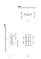
- FIG. 2 shows an arrangement state of each camera.
- FIG. 2A is a camera layout seen from above
- FIG. 2B is a camera layout seen from the front
- FIG. 2C is a camera layout seen from the side.
- imaging is performed by each camera so that the captured images of adjacent cameras overlap.
- the transmission / reception system 10A has adapters 102A to 102D provided corresponding to the cameras 101A to 101D on the transmission side.
- Each of the adapters 102A to 102D is connected to the cameras 101A to 101D with a USB (Universal Serial Bus) cable and an HDMI (High-Definition Multimedia Interface) cable.
- Each of the adapters 102A to 102D is connected to the Ethernet switch 105 with a LAN cable.
- HDMI Universal Serial Bus
- HDMI High-Definition Multimedia Interface
- Each adapter receives captured image data obtained by capturing with a corresponding camera and stores it in the storage unit. In addition, each adapter receives information about the cutout area of the corresponding camera from the reception side via the network. Each adapter cuts out the image data of the cutout area from the captured image data stored in the storage unit based on the information of the cutout area, and transmits it to the reception side via the network.
- Each camera (including the adapter) is synchronized by, for example, PTP (IEEE 1588 Precise Time Protocol) via the network, and can be V-synchronized on the network. Thereby, each camera (including the adapter) performs imaging and processing of the captured image data while maintaining V synchronization.
- PTP IEEE 1588 Precise Time Protocol
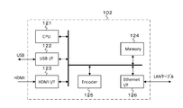
- FIG. 3 shows a configuration example of the adapter 102 (102A to 102D).
- the adapter 102 includes a CPU 121, a USB interface 122, an HDMI interface 123, a memory 124, an encoder 125, and an Ethernet interface 126.
- the USB interface 122 is an interface for performing USB communication with the camera. In this USB communication, a command command for the camera issued on the receiving side is sent to the camera. Also, in this USB communication, captured image data can be received from the camera instead of HDMI transmission described later.
- the HDMI interface 123 is an interface for performing HDMI data transmission with the camera.
- the camera is the source device and the adapter 102 is the sink device.
- this HDMI data transmission captured image data transmitted by HDMI from the camera is received.
- the memory 124 constitutes a storage unit.
- the memory 124 stores captured image data sent from the camera via HDMI data transmission or USB communication.
- the Ethernet interface 126 is an interface for connecting to a network, here, a LAN (Local Area Network). In the Ethernet interface 126, a command command for the camera issued on the receiving side is received via the network.
- the Ethernet interface 126 receives information about the cutout area of the corresponding camera sent from the receiving side via the network. Specifically, the Ethernet interface 126 receives a command packet including cutout area information from the receiving side.
- the cut-out area is an area including at least an area that overlaps a display area set on a composite image composed of the captured images of the cameras 101A to 101D among the captured images of the corresponding cameras. In this case, when there is no area overlapping the captured image of the corresponding camera, information on the cut-out area is not sent from the receiving side. Details of the cutout area will be further described in the description on the receiving side described later.
- the image data of the cutout area cut out from the captured image data stored in the memory 124 based on the information of the cutout area is transmitted to the receiving side via the network. .
- the encoder 125 cuts out the image data in the cutout area from the captured image data stored in the memory 124 based on the cutout area information received by the Ethernet interface 126, and obtains image data to be transmitted to the receiving side. Note that the encoder 125 reduces the amount of data by performing compression encoding processing such as JPEG2000 or JPEG on the image data of the cutout area as necessary.
- the transmission / reception system 10A includes a post-processing device 103 and a head mounted display (HMD) 104 as a display device on the receiving side.
- the post-processing device 103 is connected to the Ethernet switch 105 via a LAN cable.
- the head mounted display 104 is connected to the post-processing device 103 via a USB cable and an HDMI cable.
- the post-processing device 103 sets a display area on the composite image composed of the captured images of the cameras 101A to 101D, and determines an area that includes at least the areas of the captured image of a predetermined number of cameras overlapping the display area as a cutout area.
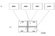
- FIG. 4A shows captured images of the cameras 101A to 101D.
- “Movie A” is a captured image of the camera 101A
- “Movie B” is a captured image of the camera 101B
- Movie C is a captured image of the camera 101C
- Movie D is a captured image of the camera 101D. It is.
- FIG. 4B shows an example of a composite image composed of images captured by the cameras 101A to 101D.
- the overlapping portions generated in the captured images of the cameras 101A to 101D are in a state of overlapping each other.
- hatched regions are shown in an overlapping state.
- the cameras 101A to 101D are HD cameras, 4K images are obtained as composite images.
- FIG. 5A shows an example of the display area set on the composite image.
- the post-processing device 103 sets the display area based on the display area control information supplied from the display device.
- the head mounted display 104 constitutes a display device, and orientation information is supplied from the head mounted display 105 to the subsequent processing apparatus 103 as display area control information.
- the head mounted display 104 acquires this orientation information by a gyro sensor, an acceleration sensor, or the like.
- the display area set on the composite image is indicated by, for example, reference coordinates (X, Y) indicating the upper left coordinates, height H, and width W.
- the reference coordinates (X, Y) are expressed in the coordinate system of the composite image.
- the reference coordinates (x, y) change according to the change in orientation.
- the height H and the width W correspond to the display resolution of the head mounted display 104, for example, HD, and are fixed values.
- FIG. 5B shows hatched areas that overlap the display areas in the captured images of the cameras 101A to 101D.
- the area overlapping the display area in each captured image is indicated by, for example, reference coordinates (x, y) indicating the upper left coordinates, height h, and width w.
- the reference coordinates (x, y) are expressed in the coordinate system of the captured image.
- FIG. 5C shows the cutout region determined in each captured image.
- This cutout area is an area including at least an area overlapping with the display area, here an area overlapping with the display area, and an extra fixed area outside this area (hereinafter, this fixed area will be referred to as “margin area” as appropriate). It is an added area. This marginal area is necessary for, for example, (1) knowing the stitch position, (2) taking lens distortion, and (3) cutting off oblique breaks that occur during projective transformation.
- the cutout region in each captured image is indicated by, for example, reference coordinates (x ′, y ′) indicating the upper left coordinates, height h ′, and width w ′.
- the reference coordinates (x ′, y ′) are expressed in the coordinate system of the captured image.
- the cutout region in each captured image may be indicated by other information, for example, upper left coordinates and lower right coordinates.
- the post-processing device 103 transmits information on the cut-out areas of the captured images of a predetermined number of cameras that overlap the display area to the transmission side via the network. In this case, the post-processing device 103 sends a command packet including information on each cut-out area to the adapter connected to the corresponding camera.
- the post-processing device 103 receives, from the transmission side, the image data of the cut-out area cut out from the captured image data of the predetermined number of cameras (here, all of the cameras 101A to 101D) via the network. . Further, the post-processing device 103 performs stitch processing, necessary lens distortion correction processing, and projective transformation processing on the received image data of each cutout region to obtain image data of a composite image corresponding to the display region. The image data of the image is sent to the head mounted display 104.
- FIG. 6 shows a configuration example of the post-processing device 103.
- the post-processing device 103 includes a CPU 131, an Ethernet interface 132, a memory 133, a signal processor 134, a USB interface 135, and an HDMI interface 136.
- the CPU 131 controls the operation of each part of the post-processing device 103. Further, the CPU 131 sets a display area on the composite image formed by the images captured by the cameras 101A to 101D based on the orientation information sent as the display area control information from the head mounted display 04, and this display area. A region including at least a region of captured images of a predetermined number of cameras overlapping with the region is determined as a cutout region (see FIG. 5). The CPU 131 knows in advance which pixel coordinate of each captured image of each camera corresponds to each pixel coordinate on the composite image formed by the captured images of the cameras 101A to 101D.
- the Ethernet interface 132 is an interface for connecting to a network, here, a LAN (Local Area Network).
- a network here, a LAN (Local Area Network).
- information on the cut-out areas of the captured images of a predetermined number of cameras overlapping the display area is transmitted to the transmission side via the network.
- the Ethernet interface 132 receives image data of a cut-out area cut out from a predetermined number of camera image data sent from the transmission side via the network via the network. .
- the memory 133 stores image data of a cut-out area cut out from the imaged image data of a predetermined number of cameras received by the Ethernet interface 132.
- the signal processor 134 performs stitch processing, necessary lens distortion correction processing, and projective transformation processing on the image data of each cutout area stored in the memory 133 to obtain image data of a composite image corresponding to the display area.
- the stitch process is performed by extracting feature points between images by a general SIFT (Scale-Invariant Feature Transform) algorithm or the like.
- this signal processor 134 performs each process after performing a compression decoding process, when the compression encoding process is performed to the image data of each cutting-out area
- the USB interface 135 is an interface for performing USB communication with the head mounted display 104.
- direction information as control information of the display area is received from the head mounted display 104.
- the HDMI interface 136 is an interface for performing HDMI data transmission with the head mounted display 104.
- the post-processing device 103 is a source device and the head mounted display 104 is a sink device.
- the image data of the composite image obtained by the signal processor 134 is transmitted to the head mounted display 104.
- FIG. 7 is a flowchart schematically showing the operation of the transmission / reception system 10A shown in FIG. The operation of the transmission / reception system 10A will be briefly described with reference to this flowchart.
- the transmission / reception system 10 ⁇ / b> A repeatedly performs the following processing (1) to (7) in real time for each frame of the head mounted display 104.
- the post-processing device 103 sets a display area on the composite image composed of the captured images of the cameras 101A to 101D based on the orientation information supplied from the head mounted display 104 (FIG. 5A). reference). Specifically, reference coordinates (X, Y) indicating the upper left coordinates of the display area in the coordinate system of the composite image, height H, and width W are set.
- the post-processing device 103 determines a clipping region for each camera image included in the display region (see FIG. 5C). Specifically, for the cutout area of each camera image, reference coordinates (x ′, y ′) indicating the upper left coordinates of the cutout area in the coordinate system of the captured image, height h ′, and width w ′ are determined.
- the post-processing device 103 sends information about the clipping region of each camera image to the corresponding camera via the network.
- the post-processing device 103 is connected to the corresponding camera with the instruction packet including the information (reference coordinates (x ′, y ′), height h ′, and width w ′) of each cut-out area. Send it to the adapter.
- the adapter 102 that has received the cutout area information from the post-processing device 103 cuts out the image data of the area indicated by the cutout area information from the captured image data of the corresponding camera. In this case, the image data is cut out not only in the area overlapping the display area but also in the marginal area outside the display area.
- the adapter 102 that has received the cut-out area information from the post-processing device 103 sends the image data cut out from the captured image data of the corresponding camera to the post-processing device 103 via the network.
- the post-processing device 103 performs stitch processing, further necessary lens distortion correction processing and projective transformation processing on the image data received from each camera (adapter), and displays image data (composite image corresponding to the display area). Image data).
- the post-processing device 103 sends the display image data to the display device, here the head mounted display 104.
- the transmission-side processing device 103 selects the transmission-side processing device 103 based on the information from the post-processing device 103 instead of all the captured image data of the cameras 101A to 101D. Only the image data of the predetermined number of cut-out areas of the cameras is sent via the network.
- FIG. 8 shows that the amount of use of the network band can be compared between when all the captured image data of the cameras 101A to 101D are sent and when the cut out image data is sent.
- the cut-out image data the case where the display area is set in the state of FIG.
- the post-processing device 103 performs stitch processing or the like on the image data of the cutout area of each camera received from the transmission side to obtain composite image image data corresponding to the display area. Since only the stitch process is performed, the processing load can be reduced.
- FIG. 9 shows a configuration example of the transmission / reception system 10B in that case. 9, parts corresponding to those in FIG. 1 are denoted by the same reference numerals, and detailed description thereof is omitted.
- the cameras 101A ′ to 101D ′ are cameras having the functions of the adapters 102A to 102D in the transmission / reception system 10A shown in FIG.
- each camera When each camera receives cutout area information from the post-processing device 103, each camera cuts out the image data of the cutout area from the captured image data and sends it to the post-processing device 103 via the network.
- the rest of the transmission / reception system 10B is configured similarly to the transmission / reception system 10A shown in FIG. This transmission / reception system 10B also operates in the same manner as the transmission / reception system 10A shown in FIG.
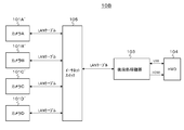
- FIG. 10 shows a configuration example of the transmission / reception system 10C in that case. 10, parts corresponding to those in FIG. 1 are denoted by the same reference numerals, and detailed description thereof is omitted.
- Each of the servers 106A to 106D accumulates captured image data obtained by capturing images with the same cameras as the cameras 101A to 101D in the transmission / reception system 10A of FIG.
- Each of the servers 106A to 106D has the functions of the adapters 102A to 102D in the transmission / reception system 10A of FIG.
- each server When each server receives cutout area information from the post-processing device 103, each server cuts out image data of the cutout region from the captured image data of the corresponding camera stored in the storage, and sends it to the post-processing device 103 via the network. send.
- the rest of the transmission / reception system 10C is configured similarly to the transmission / reception system 10A shown in FIG. This transmission / reception system 10C can also operate in the same manner as the transmission / reception system 10A shown in FIG.
- FIG. 11 shows a configuration example of the transmission / reception system 10D in that case.
- the adapter 102 has the functions of the four adapters 102A to 102D in the transmission / reception system 10A of FIG.
- the adapter 102 When the adapter 102 receives the information of the clipping region of each camera from the post-processing device 103, the adapter 102 clips the image data of the clipping region from the captured image data of each camera stored in the memory, and performs post-processing on the network. Send to device 103.
- the rest of the transmission / reception system 10D is configured similarly to the transmission / reception system 10A shown in FIG. Also in this transmission / reception system 10D, the same operation as the transmission / reception system 10A shown in FIG. 1 can be performed, and the same effect can be obtained.
- FIG. 12 shows a configuration example of the transmission / reception system 10E in that case.
- the server 106 has the functions of four servers 106A to 106D in the transmission / reception system 10C of FIG.
- the server 106 When the server 106 receives information about the clipping region of each camera from the post-processing device 103, the server 106 clips the image data of the clipping region from the captured image data of each camera stored in the storage, and performs post-processing on the network. Send to device 103.
- the rest of the transmission / reception system 10E is configured similarly to the transmission / reception system 10C shown in FIG. Also in this transmission / reception system 10E, the same operation as the transmission / reception system 10C shown in FIG. 10 can be performed, and the same effect can be obtained.
- FIG. 13 shows a configuration example of the transmission / reception system 10F in that case.
- the adapters 102A to 102D and the post-processing device 103 each have a wireless LAN (WiFi) function.
- WiFi wireless LAN
- a wireless connection is established between the post-processing device 103 and the head mounted display 104.
- this transmission / reception system 10F the same operation as the transmission / reception system 10A shown in FIG. 1 can be performed, and the same effect can be obtained.
- the configuration example of the transmission / reception system 10F illustrated in FIG. 13 is an example corresponding to the transmission / reception system 10A illustrated in FIG. 1, but detailed description is omitted, but the transmission / reception system 10B illustrated in FIG. 9 and the transmission / reception system 10C illustrated in FIG. An example corresponding to the transmission / reception system 10D shown in FIG. 11 and the transmission / reception system 10E shown in FIG. 12 can be considered in the same manner.
- FIG. 14A shows an example in which the display device is a personal computer 107
- FIG. 14B shows an example in which the display device is a tablet 108
- FIG. 14C shows a display device in the smartphone 109. An example is shown.
- FIG. 15 shows a screen display example when the display device is a personal computer 107, a tablet 108, a smartphone 109, or the like.
- the display screen can be scrolled by touching or clicking the arrows on the top, bottom, left and right arrows.
- movement information according to a user's touch or mouse click operation is supplied as control information of the display area from the personal computer 107, the tablet 108, the smartphone 109, or the like to the subsequent processing device 103.
- the post-processing device 103 moves the setting position of the display area.
- FIG. 16 shows a configuration example of a transmission / reception system 10G that captures image data of 16 cameras 101A to 101P.
- FIG. 17 shows an example of the display area set on the composite image in that case.
- the images A to P are captured images of the cameras 101A to 101P, respectively.
- the camera 101I, the camera 101M, the camera 101J, and the camera 101N are selected as the predetermined number of cameras.
- the configuration example of the transmission / reception system 10G shown in FIG. 16 is an example corresponding to the transmission / reception system 10A shown in FIG. 1, but the detailed description is omitted, but the transmission / reception system 10B shown in FIG. 9 and the transmission / reception system 10C shown in FIG.
- An example corresponding to the transmission / reception system 10D shown in FIG. 11, the transmission / reception system 10E shown in FIG. 12, and the transmission / reception system 10F shown in FIG. 13 can be considered similarly.
- a predetermined number of camera clipping region image data is transmitted from the transmission side to the subsequent processing device 103, and the subsequent processing device 103 performs stitch processing on the predetermined number of camera clipping region image data.
- an example is shown in which necessary lens distortion correction processing and projective transformation processing are performed to obtain image data of a composite image corresponding to the display area.
- these stitch processes and the like are performed on the transmission side and image data of the processed composite image is transmitted from the transmission side to the subsequent processing apparatus 103. In this case, it is not necessary to perform stitch processing or the like in the post-processing device 103, and the processing load can be greatly reduced.
- the display device such as the head mounted display 104 with the function of the post-processing device 103. In that case, it is not necessary to provide the post-processing device 103 separately from the display device, and the configuration on the receiving side can be simplified.
- this technique can also take the following structures.
- a storage unit that stores captured image data obtained by capturing images with a plurality of cameras so that adjacent captured images overlap;
- An information receiving unit that receives information on a cut-out area of a predetermined number of cameras selected from the plurality of cameras from an external device via a network;
- Image data that cuts out image data of the cutout area from the captured image data of the corresponding camera stored in the storage unit based on the information of the cutout areas of the predetermined number of cameras and transmits the image data to the external device via the network
- a transmission device comprising a transmission unit.
- the image data transmission unit The transmission apparatus according to (1), wherein the image data in the cut-out area of the predetermined number of cameras is subjected to compression encoding processing and then transmitted to the external device.
- (3) having an information receiving step of receiving information on the cut-out areas of a predetermined number of cameras selected from a plurality of cameras from an external device via a network; The plurality of cameras capture images so that adjacent captured images overlap, Image data transmission by the image data transmission unit that cuts out the image data of the cut-out area from the captured image data of the corresponding camera based on the information of the cut-out areas of the predetermined number of cameras and transmits the image data to the external device via the network
- the transmission method further comprising a step.
- a plurality of cameras that capture images so that adjacent captured images overlap;
- a plurality of adapters provided corresponding to the plurality of cameras, respectively,
- Each of the plurality of adapters A storage unit for storing captured image data obtained by capturing with a corresponding camera;
- An information receiving unit that receives information of a corresponding camera clipping region from an external device via a network;
- a transmission apparatus comprising: an image data transmission unit that extracts image data of a cutout region from captured image data stored in the storage unit based on the cutout region information and transmits the cutout image data to the external device via a network.
- a transmission apparatus comprising: an image data transmission unit configured to cut out image data of a cutout area from captured image data based on the information of the cutout area and transmit the cutout area image data to the external device via a network.
- (6) provided with a plurality of servers respectively provided corresponding to a plurality of cameras that capture images so that adjacent captured images overlap.
- Each of the plurality of servers is A storage unit for storing captured image data obtained by capturing with a corresponding camera; An information receiving unit that receives information of a corresponding camera clipping region from an external device via a network; A transmission apparatus comprising: an image data transmission unit that extracts image data of a cutout region from captured image data stored in the storage unit based on the cutout region information and transmits the cutout image data to the external device via a network.
- a display area is set on a composite image composed of captured images obtained by capturing images so that adjacent captured images are overlapped by a plurality of cameras, and a predetermined number of cameras overlapping the display areas are set.
- a cutout region determination unit that determines a region including at least a captured image region as a cutout region; An information transmission unit that transmits information of the cut-out areas of the predetermined number of cameras to an external device via a network; An image data receiving unit that receives image data of the predetermined number of camera clipping regions from the external device via the network; A receiving apparatus, comprising: an image data processing unit that performs stitch processing on the received image data of a predetermined number of cut-out areas of the camera to obtain image data of a composite image corresponding to the display area.
- the cutout region determination unit The receiving apparatus according to claim 7, wherein the display area is set based on display area control information provided from a display device that displays an image based on image data of the composite image.
- the display device is a head mounted display, The receiving apparatus according to (8), wherein the display area control information is direction information.
- the display device is a personal computer, a tablet, or a smartphone, The receiving apparatus according to (8), wherein the display area control information is movement information based on a user operation.
- the received image data of the predetermined number of clipped areas of the camera is subjected to compression encoding processing;
- the image data processing unit Any of the above (7) to (10), wherein the image data of the cut-out area of the predetermined number of cameras is subjected to the compression decoding process, and then the stitch process is performed to obtain the image data of the composite image corresponding to the display area
- a display area is set on a composite image composed of captured images obtained by capturing images so that adjacent captured images are overlapped by a plurality of cameras, and a predetermined number of cameras overlapping the display areas are set.
- a cutout region determination step for determining a region including at least a region of the captured image as a cutout region;
- An information transmission step of transmitting information on the cut-out areas of the predetermined number of cameras to an external device via a network;
- An image data receiving step of receiving image data of the cut-out area of the predetermined number of cameras from the external device by the image data receiving unit;
- a reception method comprising an image data processing step of performing stitch processing on the image data of the cut-out areas of the predetermined number of cameras to obtain image data of a composite image corresponding to the display area.
- the transmitter is A storage unit that stores captured image data obtained by capturing images with a plurality of cameras so that adjacent captured images overlap; An information receiving unit that receives information about the clipping region of a predetermined number of cameras selected from the plurality of cameras from the receiving device via the network; Image data to be extracted from the captured image data of the corresponding camera stored in the storage unit based on the information of the predetermined number of camera clipping areas and transmitted to the receiving device via the network Having a transmitter,
- the receiving device is A cutout area determining unit that sets a display area on a composite image composed of the captured images of the plurality of cameras and determines a cutout area that includes at least a predetermined number of camera image areas overlapping the display area; , An information transmission unit that transmits information of the cut-out areas of the predetermined number of cameras to the transmission device via the network; An image data receiving unit for receiving image data of the cut-out area of the predetermined number of cameras from the transmission device via
- a storage unit that stores captured image data obtained by capturing images with a plurality of cameras so that adjacent captured images overlap;
- An information receiving unit that receives information on a cut-out area of a predetermined number of cameras selected from the plurality of cameras from an external device via a network;
- An image data cutout unit that cuts out image data of the cutout region from the captured image data of the corresponding camera stored in the storage unit based on the information of the cutout region of the predetermined number of cameras;
- An image data processing unit that performs stitch processing on the image data of the cut-out areas of the predetermined number of cameras to obtain image data of a composite image;
- a transmission apparatus comprising: an image data transmission unit configured to transmit image data of the composite image to the external device via the network.
- a display area is set on a composite image composed of captured images obtained by capturing images so that adjacent captured images are overlapped by a plurality of cameras, and a predetermined number of cameras overlapping the display areas are set.
- a cutout region determination unit that determines a region including at least a captured image region as a cutout region;
- An information transmission unit that transmits information of the cut-out areas of the predetermined number of cameras to an external device via a network;
- a receiving apparatus comprising: an image data receiving unit configured to receive image data of a composite image obtained by performing stitch processing on image data of the predetermined number of clipped areas of the camera from the external device via the network.
- 10A to 10G Transmission / reception system 101A to 101P, 101A 'to 101D' ... Camera 102, 102A to 102D, 102A 'to 102D' ... Adapter 103 ... Post-processing device 104 ... Head mounted display 105 ... Ethernet switch 106, 106A to 106D ... Server 107 ... Personal computer 108 ... Tablet 109 ... Smartphone 121 ... CPU 122 ... USB interface 123 ... HDMI interface 124 ... Memory 125 ... Encoder 126 ... Ethernet interface 131 ... CPU 132 ... Ethernet interface 133 ... Memory 134 ... Signal processor 135 ... USB interface 136 ... HDMI interface
Landscapes
- Engineering & Computer Science (AREA)
- Multimedia (AREA)
- Signal Processing (AREA)
- Studio Devices (AREA)
- Two-Way Televisions, Distribution Of Moving Picture Or The Like (AREA)
- Image Processing (AREA)
- Closed-Circuit Television Systems (AREA)
Abstract
Priority Applications (3)
| Application Number | Priority Date | Filing Date | Title |
|---|---|---|---|
| JP2017551909A JP6930423B2 (ja) | 2015-11-17 | 2016-11-16 | 受信装置、受信方法および送受信システム |
| CN201680065633.8A CN108353195A (zh) | 2015-11-17 | 2016-11-16 | 发送设备、发送方法、接收设备、接收方法和发送/接收系统 |
| US15/773,080 US20180324475A1 (en) | 2015-11-17 | 2016-11-16 | Transmission device, transmission method, reception device, reception method, and transmission/reception system |
Applications Claiming Priority (2)
| Application Number | Priority Date | Filing Date | Title |
|---|---|---|---|
| JP2015-224621 | 2015-11-17 | ||
| JP2015224621 | 2015-11-17 |
Publications (1)
| Publication Number | Publication Date |
|---|---|
| WO2017086355A1 true WO2017086355A1 (fr) | 2017-05-26 |
Family
ID=58718907
Family Applications (1)
| Application Number | Title | Priority Date | Filing Date |
|---|---|---|---|
| PCT/JP2016/083985 WO2017086355A1 (fr) | 2015-11-17 | 2016-11-16 | Dispositif d'émission, procédé d'émission, dispositif de réception, procédé de réception et système d'émission/réception |
Country Status (4)
| Country | Link |
|---|---|
| US (1) | US20180324475A1 (fr) |
| JP (1) | JP6930423B2 (fr) |
| CN (1) | CN108353195A (fr) |
| WO (1) | WO2017086355A1 (fr) |
Cited By (1)
| Publication number | Priority date | Publication date | Assignee | Title |
|---|---|---|---|---|
| WO2020039992A1 (fr) * | 2018-08-20 | 2020-02-27 | ソニーセミコンダクタソリューションズ株式会社 | Dispositif de traitement d'images, et système de traitement d'images |
Families Citing this family (1)
| Publication number | Priority date | Publication date | Assignee | Title |
|---|---|---|---|---|
| JP7314798B2 (ja) * | 2017-10-16 | 2023-07-26 | ソニーグループ株式会社 | 撮像装置、画像処理装置、及び、画像処理方法 |
Citations (2)
| Publication number | Priority date | Publication date | Assignee | Title |
|---|---|---|---|---|
| JP2001320616A (ja) * | 2000-02-29 | 2001-11-16 | Matsushita Electric Ind Co Ltd | 撮像システム |
| JP2005333552A (ja) * | 2004-05-21 | 2005-12-02 | Viewplus Inc | パノラマ映像配信システム |
Family Cites Families (6)
| Publication number | Priority date | Publication date | Assignee | Title |
|---|---|---|---|---|
| JP4345829B2 (ja) * | 2007-03-09 | 2009-10-14 | ソニー株式会社 | 画像表示システム、画像表示装置、画像表示方法およびプログラム |
| JP2014039201A (ja) * | 2012-08-17 | 2014-02-27 | Nippon Telegr & Teleph Corp <Ntt> | 複数カメラ利用時のroiを用いた遠隔制御の方法 |
| CN104781873B (zh) * | 2012-11-13 | 2017-06-06 | 索尼公司 | 图像显示装置、图像显示方法、移动装置、图像显示系统 |
| JP6002591B2 (ja) * | 2013-01-31 | 2016-10-05 | 日本電信電話株式会社 | パノラマ映像情報再生方法、パノラマ映像情報再生システム、及びプログラム |
| CN104219584B (zh) * | 2014-09-25 | 2018-05-01 | 广东京腾科技有限公司 | 基于增强现实的全景视频交互方法和系统 |
| CN104301677B (zh) * | 2014-10-16 | 2018-06-15 | 北京十方慧通科技有限公司 | 面向大场景的全景视频监控的方法及装置 |
-
2016
- 2016-11-16 JP JP2017551909A patent/JP6930423B2/ja active Active
- 2016-11-16 US US15/773,080 patent/US20180324475A1/en not_active Abandoned
- 2016-11-16 CN CN201680065633.8A patent/CN108353195A/zh active Pending
- 2016-11-16 WO PCT/JP2016/083985 patent/WO2017086355A1/fr active Application Filing
Patent Citations (2)
| Publication number | Priority date | Publication date | Assignee | Title |
|---|---|---|---|---|
| JP2001320616A (ja) * | 2000-02-29 | 2001-11-16 | Matsushita Electric Ind Co Ltd | 撮像システム |
| JP2005333552A (ja) * | 2004-05-21 | 2005-12-02 | Viewplus Inc | パノラマ映像配信システム |
Cited By (3)
| Publication number | Priority date | Publication date | Assignee | Title |
|---|---|---|---|---|
| WO2020039992A1 (fr) * | 2018-08-20 | 2020-02-27 | ソニーセミコンダクタソリューションズ株式会社 | Dispositif de traitement d'images, et système de traitement d'images |
| US11647284B2 (en) | 2018-08-20 | 2023-05-09 | Sony Semiconductor Solutions Corporation | Image processing apparatus and image processing system with image combination that implements signal level matching |
| US12058438B2 (en) | 2018-08-20 | 2024-08-06 | Sony Semiconductor Solutions Corporation | Image processing apparatus and image processing system with gain correction based on correction control information |
Also Published As
| Publication number | Publication date |
|---|---|
| JP6930423B2 (ja) | 2021-09-01 |
| US20180324475A1 (en) | 2018-11-08 |
| CN108353195A (zh) | 2018-07-31 |
| JPWO2017086355A1 (ja) | 2018-09-06 |
Similar Documents
| Publication | Publication Date | Title |
|---|---|---|
| US10594988B2 (en) | Image capture apparatus, method for setting mask image, and recording medium | |
| Schneider et al. | Augmented reality based on edge computing using the example of remote live support | |
| KR102375307B1 (ko) | 가상 현실 뷰포트를 공유하기 위한 방법, 장치, 및 시스템 | |
| JP6131950B2 (ja) | 情報処理装置、および情報処理方法、並びにプログラム | |
| KR101644868B1 (ko) | 단말기 간 이미지 공유 방법, 단말 장치 및 통신 시스템 | |
| JP6386809B2 (ja) | 情報処理装置およびその制御方法、システム、並びにプログラム | |
| WO2015142971A1 (fr) | Partage de vidéo à vue panoramique commandé par un récepteur | |
| CN103078924A (zh) | 视野共享方法及设备 | |
| WO2020125604A1 (fr) | Procédé, appareil, dispositif et support de stockage pour la transmission de données | |
| EP3065413B1 (fr) | Système de transmission multimédia en continu et son procédé de commande | |
| JP6669959B2 (ja) | 画像処理装置、撮影装置、画像処理方法、画像処理プログラム | |
| CN107105124B (zh) | 用于平台和图像设备之间的通信的协议 | |
| US20200259880A1 (en) | Data processing method and apparatus | |
| WO2014185169A1 (fr) | Dispositif de traitement d'image, méthode de traitement d'image, et programme | |
| JP2015114424A (ja) | 電子機器、表示装置、方法、及びプログラム | |
| WO2017013986A1 (fr) | Dispositif de traitement d'informations, terminal, et système de communication à distance | |
| WO2017086355A1 (fr) | Dispositif d'émission, procédé d'émission, dispositif de réception, procédé de réception et système d'émission/réception | |
| US20240015264A1 (en) | System for broadcasting volumetric videoconferences in 3d animated virtual environment with audio information, and procedure for operating said device | |
| US20220301184A1 (en) | Accurate optical flow interpolation optimizing bi-directional consistency and temporal smoothness | |
| US20180012410A1 (en) | Display control method and device | |
| JP7326774B2 (ja) | 画像処理システム、撮像装置、情報処理装置、画像処理方法及びプログラム | |
| JP5864371B2 (ja) | 静止画自動生成システム、静止画自動生成システムにおける作業者用情報処理端末及び指示者用情報処理端末、及び判定装置 | |
| WO2019090473A1 (fr) | Procédé et système d'affichage pour image panoramique, et procédé de traitement et station au sol pour image panoramique | |
| JP2019129466A (ja) | 映像表示装置 | |
| JP6306822B2 (ja) | 画像処理装置、画像処理方法、および画像処理プログラム |
Legal Events
| Date | Code | Title | Description |
|---|---|---|---|
| 121 | Ep: the epo has been informed by wipo that ep was designated in this application |
Ref document number: 16866356 Country of ref document: EP Kind code of ref document: A1 |
|
| ENP | Entry into the national phase |
Ref document number: 2017551909 Country of ref document: JP Kind code of ref document: A |
|
| WWE | Wipo information: entry into national phase |
Ref document number: 15773080 Country of ref document: US |
|
| NENP | Non-entry into the national phase |
Ref country code: DE |
|
| 122 | Ep: pct application non-entry in european phase |
Ref document number: 16866356 Country of ref document: EP Kind code of ref document: A1 |