WO2017086299A1 - 撮影装置及びその制御方法 - Google Patents
撮影装置及びその制御方法 Download PDFInfo
- Publication number
- WO2017086299A1 WO2017086299A1 PCT/JP2016/083781 JP2016083781W WO2017086299A1 WO 2017086299 A1 WO2017086299 A1 WO 2017086299A1 JP 2016083781 W JP2016083781 W JP 2016083781W WO 2017086299 A1 WO2017086299 A1 WO 2017086299A1
- Authority
- WO
- WIPO (PCT)
- Prior art keywords
- color temperature
- image
- unit
- information
- color
- Prior art date
- Legal status (The legal status is an assumption and is not a legal conclusion. Google has not performed a legal analysis and makes no representation as to the accuracy of the status listed.)
- Ceased
Links
Images







Classifications
-
- G—PHYSICS
- G03—PHOTOGRAPHY; CINEMATOGRAPHY; ANALOGOUS TECHNIQUES USING WAVES OTHER THAN OPTICAL WAVES; ELECTROGRAPHY; HOLOGRAPHY
- G03B—APPARATUS OR ARRANGEMENTS FOR TAKING PHOTOGRAPHS OR FOR PROJECTING OR VIEWING THEM; APPARATUS OR ARRANGEMENTS EMPLOYING ANALOGOUS TECHNIQUES USING WAVES OTHER THAN OPTICAL WAVES; ACCESSORIES THEREFOR
- G03B13/00—Viewfinders; Focusing aids for cameras; Means for focusing for cameras; Autofocus systems for cameras
- G03B13/02—Viewfinders
-
- G—PHYSICS
- G03—PHOTOGRAPHY; CINEMATOGRAPHY; ANALOGOUS TECHNIQUES USING WAVES OTHER THAN OPTICAL WAVES; ELECTROGRAPHY; HOLOGRAPHY
- G03B—APPARATUS OR ARRANGEMENTS FOR TAKING PHOTOGRAPHS OR FOR PROJECTING OR VIEWING THEM; APPARATUS OR ARRANGEMENTS EMPLOYING ANALOGOUS TECHNIQUES USING WAVES OTHER THAN OPTICAL WAVES; ACCESSORIES THEREFOR
- G03B13/00—Viewfinders; Focusing aids for cameras; Means for focusing for cameras; Autofocus systems for cameras
- G03B13/02—Viewfinders
- G03B13/04—Viewfinders of direct vision type, e.g. frame, sighting mark
-
- G—PHYSICS
- G03—PHOTOGRAPHY; CINEMATOGRAPHY; ANALOGOUS TECHNIQUES USING WAVES OTHER THAN OPTICAL WAVES; ELECTROGRAPHY; HOLOGRAPHY
- G03B—APPARATUS OR ARRANGEMENTS FOR TAKING PHOTOGRAPHS OR FOR PROJECTING OR VIEWING THEM; APPARATUS OR ARRANGEMENTS EMPLOYING ANALOGOUS TECHNIQUES USING WAVES OTHER THAN OPTICAL WAVES; ACCESSORIES THEREFOR
- G03B17/00—Details of cameras or camera bodies; Accessories therefor
- G03B17/18—Signals indicating condition of a camera member or suitability of light
- G03B17/20—Signals indicating condition of a camera member or suitability of light visible in viewfinder
-
- H—ELECTRICITY
- H04—ELECTRIC COMMUNICATION TECHNIQUE
- H04N—PICTORIAL COMMUNICATION, e.g. TELEVISION
- H04N23/00—Cameras or camera modules comprising electronic image sensors; Control thereof
-
- H—ELECTRICITY
- H04—ELECTRIC COMMUNICATION TECHNIQUE
- H04N—PICTORIAL COMMUNICATION, e.g. TELEVISION
- H04N23/00—Cameras or camera modules comprising electronic image sensors; Control thereof
- H04N23/60—Control of cameras or camera modules
- H04N23/62—Control of parameters via user interfaces
-
- H—ELECTRICITY
- H04—ELECTRIC COMMUNICATION TECHNIQUE
- H04N—PICTORIAL COMMUNICATION, e.g. TELEVISION
- H04N23/00—Cameras or camera modules comprising electronic image sensors; Control thereof
- H04N23/60—Control of cameras or camera modules
- H04N23/63—Control of cameras or camera modules by using electronic viewfinders
-
- H—ELECTRICITY
- H04—ELECTRIC COMMUNICATION TECHNIQUE
- H04N—PICTORIAL COMMUNICATION, e.g. TELEVISION
- H04N23/00—Cameras or camera modules comprising electronic image sensors; Control thereof
- H04N23/60—Control of cameras or camera modules
- H04N23/63—Control of cameras or camera modules by using electronic viewfinders
- H04N23/631—Graphical user interfaces [GUI] specially adapted for controlling image capture or setting capture parameters
-
- H—ELECTRICITY
- H04—ELECTRIC COMMUNICATION TECHNIQUE
- H04N—PICTORIAL COMMUNICATION, e.g. TELEVISION
- H04N23/00—Cameras or camera modules comprising electronic image sensors; Control thereof
- H04N23/60—Control of cameras or camera modules
- H04N23/63—Control of cameras or camera modules by using electronic viewfinders
- H04N23/633—Control of cameras or camera modules by using electronic viewfinders for displaying additional information relating to control or operation of the camera
-
- H—ELECTRICITY
- H04—ELECTRIC COMMUNICATION TECHNIQUE
- H04N—PICTORIAL COMMUNICATION, e.g. TELEVISION
- H04N23/00—Cameras or camera modules comprising electronic image sensors; Control thereof
- H04N23/60—Control of cameras or camera modules
- H04N23/63—Control of cameras or camera modules by using electronic viewfinders
- H04N23/633—Control of cameras or camera modules by using electronic viewfinders for displaying additional information relating to control or operation of the camera
- H04N23/635—Region indicators; Field of view indicators
-
- H—ELECTRICITY
- H04—ELECTRIC COMMUNICATION TECHNIQUE
- H04N—PICTORIAL COMMUNICATION, e.g. TELEVISION
- H04N23/00—Cameras or camera modules comprising electronic image sensors; Control thereof
- H04N23/60—Control of cameras or camera modules
- H04N23/667—Camera operation mode switching, e.g. between still and video, sport and normal or high- and low-resolution modes
-
- H—ELECTRICITY
- H04—ELECTRIC COMMUNICATION TECHNIQUE
- H04N—PICTORIAL COMMUNICATION, e.g. TELEVISION
- H04N23/00—Cameras or camera modules comprising electronic image sensors; Control thereof
- H04N23/80—Camera processing pipelines; Components thereof
- H04N23/84—Camera processing pipelines; Components thereof for processing colour signals
- H04N23/88—Camera processing pipelines; Components thereof for processing colour signals for colour balance, e.g. white-balance circuits or colour temperature control
Definitions
- the present invention relates to a photographing apparatus having a hybrid viewfinder and a control method thereof.
- the hybrid viewfinder allows one or both of an optical image of a subject and a captured image of the subject obtained by capturing the optical image with an image sensor to be displayed in the viewfinder.
- the hybrid viewfinder it is possible to display a captured image superimposed or close to an optical image.
- the user can perform framing of the subject with the optical image while confirming the image obtained by photographing in advance.
- the AWB adjustment function is a function for automatically adjusting the color temperature representing the color of an image so that a white subject is photographed white by detecting the type of light source (sun, fluorescent light, incandescent light bulb, etc.) during photographing.
- the color temperature may be inappropriately adjusted by erroneously detecting the type of light source. For example, in a shooting scene that contains a lot of green, such as a forest, the type of light source should be detected as “sun”, but may be erroneously detected as “fluorescent light”.
- An object of the present invention is to provide a photographing apparatus and a control method thereof that can adjust the color temperature of an image with high accuracy.
- the photographing apparatus of the present invention includes an image sensor, a finder unit, an in-finder information display unit, a color temperature adjustment unit, target color temperature information, and a display control unit.
- the image sensor generates an image based on an optical image incident through the photographing lens.
- the finder unit is configured so that an optical image can be observed.
- the in-finder information display unit displays information in an observable manner by superimposing or bringing information close to the optical image.
- the color temperature adjustment unit adjusts the color temperature of the image based on the color temperature adjustment operation.
- the target color temperature information represents a color temperature that is a target for adjusting the color temperature as information by controlling the information display unit in the finder.
- the display control unit displays image color temperature information indicating the color temperature of the image.
- the display control unit preferably displays the image color temperature information of the image after the color temperature is adjusted by the color temperature adjustment unit when the color temperature adjustment operation is performed.
- An image storage unit, a first region designating unit for designating a first designated region in a stored image stored in the image storage unit, and a color temperature of the first designated region designated by the first region designating unit are acquired. It is preferable that the target color temperature information represents the color temperature of the first designated region acquired by the first color temperature acquisition unit.
- the stored image is preferably an image obtained by photographing.
- the stored image may be a color chart in which colors having different color temperatures are arranged.
- the first designated area is displayed so as to be identifiable with respect to the color chart.
- the first color temperature acquisition unit calculates an average color temperature in the first designated area.
- a second region designating unit for designating the second designated region in the optical image observed in the viewfinder unit, and a second color for obtaining the color temperature of the image corresponding to the second designated region designated by the second region designating unit.
- a temperature acquisition unit, and the image color temperature information preferably represents the color temperature of the image corresponding to the second designated region.
- the second color temperature acquisition unit calculates an average color temperature in the second designated area.
- a color temperature difference calculating unit that calculates a color temperature difference between the color temperature of the first specified region and the color temperature of the second specified region is provided, and the display control unit adds information to the target color temperature information and the image color temperature information as information. It is preferable to display color temperature difference information representing the color temperature difference.
- the display control unit controls the in-finder information display unit to set the first area and the second area adjacent to each other, and to display the color of the color temperature represented by the image color temperature information in the first area.
- the color of the color temperature represented by the target color temperature information is displayed in the second area.
- the viewfinder has a light-shielding part that can partially shield the optical image, and the information display part in the finder sets the first area and the second area in the part that is partially shielded by the light-shielding part. It is preferable to do.
- the control method of the photographing apparatus includes an image pickup device that generates an image based on an optical image incident through a photographing lens, a finder unit configured to observe the optical image, and information in the optical image in the finder unit.
- a finder control method comprising: an in-finder information display unit that displays images in an observable manner superimposed on each other, and a color temperature adjustment unit that adjusts the color temperature of an image based on a color temperature adjustment operation.
- the information display unit is controlled to display, as information, target color temperature information representing the color temperature targeted for color temperature adjustment and image color temperature information representing the color temperature of the image.
- the target color temperature information representing the color temperature targeted for color temperature adjustment and the image color temperature information representing the color temperature of the image are superimposed on or close to the optical image. Since the image is displayed so as to be observable, the color temperature of the image can be adjusted with high accuracy.
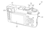
- a digital camera 11 as a photographing apparatus includes a camera body 12, a lens barrel 13, a top operation unit 14, a rear display unit 15, a rear operation unit 16, and a finder device (finder unit) 17. .
- the viewfinder device 17 includes an optical viewfinder (OVF) mode (hereinafter referred to as OVF mode), an electronic viewfinder (EVF) mode (hereinafter referred to as EVF mode), and a hybrid viewfinder (HVF). ; Mode switching between Hybrid (View Finder) mode (hereinafter referred to as HVF mode) is possible.
- OVF optical viewfinder
- EVF electronic viewfinder
- HVF hybrid viewfinder
- the OVF mode it is possible to observe an OVF image in which an optical image of a subject and an information image representing electronic information such as shooting conditions are superimposed.
- the EVF mode a captured image and an information image obtained by capturing an optical image can be observed.
- the HVF mode makes it possible to observe both an optical image and a captured image.
- the OVF mode includes a color temperature adjustment mode that allows the user to manually adjust the color temperature of the captured image.
- image color temperature information representing the color temperature of the captured image and target color temperature information representing the color temperature targeted for color temperature adjustment are displayed as electronic information.
- the digital camera 11 is provided with a target color temperature information setting mode for the user to set target color temperature information.
- the target color temperature information setting mode is a mode in which an ideal reference color of a photographed image that the user wants to obtain by photographing is registered in advance before photographing. Switching to the color temperature adjustment mode or the target color temperature information setting mode is performed by operating the upper surface operation unit 14 and is executed by the main control unit 32 described later.
- the lens barrel 13 is provided on the front surface of the camera body 12 and holds the photographing lens 18.
- the lens barrel 13 is provided with a control ring 13a.
- the control ring 13a is attached to the lens barrel 13 so as to be rotatable about the optical axis of the photographing lens 18.
- the control ring 13a is used for various operations such as setting switching. In the color temperature adjustment mode, the control ring 13a is used for a color temperature adjustment operation by the user.
- the amount of rotation of the control ring 13a corresponds to the color temperature adjustment operation amount (color temperature shift amount).
- the main control unit 32 described later detects the rotational position of the control ring 13a via a position sensor (not shown), and obtains the rotation amount from the reference position.
- a color temperature adjusting unit 74 described later obtains a color temperature shift amount corresponding to the rotation amount obtained by the main control unit 32.
- the upper surface operation unit 14 is provided on the upper surface of the camera body 12, and includes a power button 14a, a release button 14b, a mode switching dial 14c, a finder switching lever 14d, and the like.
- the power button 14a is operated when turning on or off the power (not shown) of the digital camera 11.
- the release button 14b is operated when shooting is performed.
- the mode switching dial 14c is operated when the operation mode is switched among the shooting mode, the image reproduction mode, the setting mode, and the like.
- the mode switching dial 14c is also used for setting operations of the above-described color temperature adjustment mode and target color temperature information setting mode.
- the finder switching lever 14d is operated when the mode of the finder device 17 is switched between the OVF mode, the EVF mode, and the HVF mode.
- the shooting modes include a still image shooting mode for acquiring still images and a moving image shooting mode for acquiring moving images.
- the image playback mode the image acquired in the still image shooting mode or the moving image shooting mode is played back and displayed on the rear display unit 15.
- the release button 14b has a two-stage stroke type switch (not shown) composed of an S1 switch and an S2 switch.
- a shooting preparation operation such as an autofocus (AF) operation.
- the release button 14b is further pressed (fully pressed) from this state and the S2 switch is turned on, the digital camera 11 performs a photographing operation.
- the rear display unit 15 is provided on the rear surface of the camera body 12, and displays captured images acquired in various shooting modes, menu screens for performing various settings, and the like.
- the rear display unit 15 may be a touch screen that combines a display device such as an LCD (Liquid Crystal Display) and an input device such as a touch pad. In this case, various settings can be performed by a touch operation on the touch screen.
- LCD Liquid Crystal Display
- the back operation unit 16 is provided on the back of the camera body 12.
- the back operation unit 16 is used when the user sets target color temperature information in the target color temperature information setting mode in addition to various setting operations.
- the finder device 17 includes a finder window 17a for capturing an optical image of a subject, and a finder eyepiece 17b through which the user's eyes are in contact.
- the finder window 17 a is provided on the front side of the camera body 12.
- the viewfinder eyepiece 17 b is provided on the back side of the camera body 12.
- a slot (not shown) for mounting a recording medium 41 (see FIG. 3) described later is provided on the bottom of the camera body 12.
- a diaphragm 30 and an image sensor 31 are provided in the lens barrel 13 along the optical axis LA of the photographing lens 18.
- the diaphragm 30 is driven and controlled by the main controller 32 and adjusts the amount of light incident on the image sensor 31.
- An optical image of a subject that has passed through the photographing lens 18 and whose light amount has been adjusted by the diaphragm 30 enters the image sensor 31.
- the imaging element 31 may be disposed outside the lens barrel 13.
- the photographing lens 18 includes a zoom lens 18a and a focus lens 18b.
- a lens driving unit 24 is connected to the photographing lens 18.
- the lens driving unit 24 moves the zoom lens 18 a and the focus lens 18 b in the optical axis direction under the control of the main control unit 32. Zooming is performed by driving the zoom lens 18a, and AF operation is performed by driving the focus lens 18b.
- the imaging element 31 is, for example, a single-plate color imaging CMOS (Complementary Metal Oxide Semiconductor) type image sensor having RGB color filters.
- the imaging element 31 has a light receiving surface constituted by a plurality of pixels (not shown) arranged in a two-dimensional matrix. Each pixel includes a photoelectric conversion element, and captures an optical image formed on the light receiving surface by photoelectric conversion to generate an imaging signal. Further, the image sensor 31 has an electronic shutter function, and the shutter speed (charge accumulation time) can be adjusted.
- the imaging device 31 includes a signal processing circuit.
- the signal processing circuit include a noise removal circuit, an auto gain controller, an A / D (Analog / Digital) conversion circuit, and the like (none of which are shown).
- the noise removal circuit performs noise removal processing on the imaging signal.
- the auto gain controller amplifies the level of the imaging signal to an optimum value.
- the A / D conversion circuit converts the imaging signal into a digital signal and outputs it from the imaging element 31.
- the output signal of the image sensor 31 is RGB format image data (so-called RAW data) having one color signal for each pixel.
- the image sensor 31 and the main control unit 32 are connected to a bus 33.
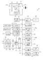
- the bus 33 includes a memory control unit 34, a digital signal processing unit 35, a target color temperature setting processing unit 36a, a color temperature adjustment processing unit 36b, a media control unit 37, a rear display control unit 38, and an EVF display control unit. (Display control unit) 39 is connected.
- the memory control unit 34 is connected to a memory 40 for temporary storage such as SDRAM (Synchronous Dynamic Random Access Memory).
- SDRAM Synchronous Dynamic Random Access Memory
- the memory control unit 34 inputs and stores the RGB format image data output from the image sensor 31 into the memory 40. Further, the memory control unit 34 outputs the image data in the RGB format stored in the memory 40 to the digital signal processing unit 35.
- the digital signal processing unit 35 performs defect correction processing, demosaic processing, gamma correction processing, RGB gain correction processing, YC conversion processing, and the like on the RGB format image data input from the memory control unit 34, and luminance signal Y YC format image data (YC image data) including the color difference signal C and the color difference signal C is generated.
- the digital signal processing unit 35 outputs the generated image data in the YC format to the memory control unit 34 so as to be stored in the memory 40.
- the digital signal processing unit 35 generates an image file by performing compression processing according to various shooting modes on the YC image data. Specifically, in the still image shooting mode, the digital signal processing unit 35 compresses YC image data according to, for example, the JPEG (Joint Photographic Experts Group) standard or the like to generate compressed image data. In the moving image shooting mode, the digital signal processing unit 35 generates moving image data obtained by compressing YC image data of a plurality of frames obtained by moving image shooting according to, for example, MPEG (Moving / Picture / Experts / Group) -4 standard. The digital signal processing unit 35 outputs the generated image file to the media control unit 37.
- JPEG Joint Photographic Experts Group
- the media control unit 37 controls recording and reading of an image file on a recording medium 41 as an image storage unit.
- the recording medium 41 is a memory card with a built-in flash memory, for example.
- the still image shooting mode the compressed image data generated by the digital signal processing unit 35 is recorded on the recording medium 41.
- the moving image shooting mode the moving image data generated by the digital signal processing unit 35 is recorded on the recording medium 41.
- sound is acquired and recorded in addition to the image.
- description of the configuration related to acquisition and recording of sound is omitted.
- the target color temperature setting processing unit 36 a includes a first color temperature acquisition unit 71 and a target color temperature storage unit 72.
- the color temperature adjustment processing unit 36 b includes a second color temperature acquisition unit 73 and a color temperature adjustment unit 74.
- the target color temperature setting processing unit 36a operates in the target color temperature information setting mode, and allows the user to set the target color temperature.
- the color temperature adjustment processing unit 36b operates in the color temperature adjustment mode, and enables acquisition of the color temperature of the captured image and adjustment of the color temperature of the captured image in accordance with a user operation.
- the rear display control unit 38 controls image display on the rear display unit 15. Specifically, the rear display control unit 38 generates a video signal based on the NTSC (National Television System Committee) standard based on the YC image data generated by the digital signal processing unit 35 and generates the rear display unit 15. Output to.
- NTSC National Television System Committee
- the EVF display control unit 39 generates a video signal based on the YC image data similarly to the rear display control unit 38, and outputs the video signal to the EVFLCD 42 described later.
- the finder device 17 is provided with an EVFLCD 42 as an in-finder information display unit, a prism 43, and an OVF shutter 44 as a light shielding unit.
- the EVFLCD 42 displays various images acquired in various shooting modes.
- an area for displaying an image is set according to the finder mode.
- the EVF LCD 42 displays an image display area (not shown) in which a picked-up image obtained by picking up an optical image of a subject by the image pickup device 31 and an information display area (not shown) in which an information image is displayed. Is set).
- the information display area is set around the image display area, for example, on the lower side.
- the captured image is a display image of YC image data generated by the digital signal processing unit 35.
- the information image is a display image of information image data generated by the main control unit 32.
- the information image data is generated based on shooting information such as shooting conditions.
- the shooting conditions include shutter speed, aperture value, ISO sensitivity, and the like.
- the shooting conditions can be set by operating the upper surface operation unit 14, for example.
- an information display area is set on the EVF LCD 42.
- the information display area is set on the lower side, for example, as in the EVF mode.
- the image display area in the EVF mode is not displayed.
- a sub display area (not shown) in which a captured image is displayed is set in the EVF LCD 42.
- the sub display area is set adjacent to the information display area at the lower right of the screen, for example.
- the image display area in the EVF mode is not displayed.
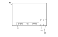
- the EVFLCD 42 has an information display area 61, an image color temperature information display area (first area) 62, and a target color temperature information display area ( (Second area) 63 is set. Other areas (image display areas in the EVF mode) are not displayed.
- the information display area 61 “1/2000” is a shutter speed, “ISO200” is an ISO sensitivity, and “F5.6” is a display example of an aperture value.
- image color temperature information display area 62 image color temperature information indicating the color temperature of the captured image is displayed.
- the image color temperature information display area 62 displays a single color image corresponding to the color temperature of the captured image as the image color temperature information.
- target color temperature information display area 63 target color temperature information representing the color temperature targeted for color temperature adjustment is displayed.
- the target color temperature information display area 63 displays a single color image corresponding to the target color temperature as the target color temperature information.
- the image color temperature information display area 62 and the target color temperature information display area 63 are set adjacent to each other. For example, the image color temperature information display area 62 and the target color temperature information display area 63 are set adjacent to the information display area 61 at the lower right of the screen.
- the prism 43 includes a half mirror 48 as an optical path integration unit.
- the half mirror 48 makes an angle of 45 degrees with respect to the first optical path 49 through which the optical image of the subject incident on the finder window 17a propagates and the second optical path 50 through which the display image displayed on the EVFLCD 42 propagates. Has been placed.
- the half mirror 48 integrates the first optical path 49 and the second optical path 50 into a third optical path 51.
- a finder eyepiece 17 b is disposed on the third optical path 51.
- the half mirror 48 partially transmits an optical image propagating on the first optical path 49 and guides it to the third optical path 51, and partially reflects a display image propagating on the second optical path 50 to guide it to the third optical path 51. . Thereby, the optical image and the display image are guided to the finder eyepiece 17b.
- the OVF shutter 44 is a liquid crystal shutter and is disposed on the first optical path 49.
- the light transmittance of the OVF shutter 44 is controlled by the main controller 32 to a low transmittance (for example, 0%) or a high transmittance (for example, 100%).
- the OVF shutter 44 shields the optical image from being incident on the prism 43 in an area where the light transmittance is low, and transmits the optical image in an area where the light transmittance is high. 43 is incident.
- the main control unit 32 grasps each display area of the EVF LCD 42 and changes the light transmittance of the OVF shutter 44 in whole or in part according to the mode of the finder.
- the main control unit 32 controls the OVF shutter 44 so that the area corresponding to the image display area and the information display area of the EVF LCD 42 has a low transmittance. In this case, the entire OVF shutter 44 has a low transmittance.
- the OVF shutter 44 having a low transmittance shields the optical image.
- a captured image is displayed in the image display area of the EVFLCD 42, and an information image is displayed in the information display area. Thereby, in the EVF mode, the captured image and the information image can be observed from the finder eyepiece 17b.
- the main control unit 32 controls the OVF shutter 44 so that the area corresponding to the image display area of the EVF LCD 42 has a high transmittance and the area corresponding to the information display area has a low transmittance.
- the OVF shutter 44 transmits an optical image in an area corresponding to the image display area and does not transmit an optical image in an area corresponding to the information display area.
- the image display area of the EVFLCD 42 is not displayed, and an information image is displayed in the information display area.
- an OVF image in which the information image displayed on the EVF LCD 42 is superimposed on the optical image can be observed from the viewfinder eyepiece 17b.
- the main control unit 32 controls the OVF shutter 44 so that the area corresponding to the image display area of the EVFLCD 42 has a high transmittance, and the areas corresponding to the information display area and the sub display area have a low transmittance. Rate.
- the OVF shutter 44 transmits an optical image in an area corresponding to the image display area and does not transmit an optical image in areas corresponding to the information display area and the sub display area.
- the image display area of the EVFLCD 42 is not displayed, the captured image is displayed in the sub display area, and the information image is displayed in the information display area.
- the main control unit 32 controls the OVF shutter 44 so that the area corresponding to the image display area of the EVFLCD 42 has a high transmittance, and an information display area 61 and an image color temperature information display area 62 are displayed. , And an area corresponding to the target color temperature information display area 63 is set to a low transmittance.
- the OVF shutter 44 transmits an optical image in an area corresponding to the image display area, and does not transmit an optical image in an area corresponding to the information display area 61, the image color temperature information display area 62, and the target color temperature information display area 63.
- the image display area of the EVFLCD 42 is not displayed, the information image is displayed in the information display area 61, the image color temperature information is displayed in the image color temperature information display area 62, and the target color temperature information display area 63 is the target. Color temperature information is displayed.
- a finder observation image 68 in which the information image 65, the image color temperature information 66, and the target color temperature information 67 are superimposed on the optical image 64 is displayed in the finder eyepiece. Observation is possible from the part 17b.
- Superimposition means that the optical image 64 is partially shielded from light and an image or information is displayed on the shielded part.
- the first color temperature acquisition unit 71 acquires a target color temperature representing a color temperature targeted for color temperature adjustment in the color temperature information setting mode. Specifically, in the color temperature information setting mode, the past image (stored image) stored in the recording medium 41 as the image storage unit is displayed on the EVFLCD 42 under the control of the main control unit 32. The first designated area is designated in one past image. The first color temperature acquisition unit 71 obtains the color temperature of the first designated area in the past image, and obtains the obtained color temperature as the target color temperature.
- the past image is an image obtained by photographing, and is not limited to the recording medium 41, and may be stored in the memory 40 that is an internal memory.
- the main control unit 32 has a first area designating unit 76, and allows the first designated area to be designated in one past image based on the operation of the back surface operation unit 16 by the user. .
- the first color temperature acquisition unit 71 obtains the average color of the first designated area, and obtains the obtained average color temperature as the target color temperature.
- the average color corresponds to the ratio of the average values of the R signal, G signal, and B signal in the first designated area.
- the first designated area 76 can designate the first designated area a plurality of times.
- the first color temperature acquisition unit 71 acquires the target color temperature every time the first specified area is specified.
- the target color temperature storage unit 72 stores the target color temperature acquired by the first color temperature acquisition unit 71. When a plurality of target color temperatures are acquired by the first color temperature acquisition unit 71, the target color temperature storage unit 72 stores the acquired target color temperatures.
- the second color temperature acquisition unit 73 acquires an image color temperature representing the color temperature of the captured image in the color temperature adjustment mode. Specifically, in the color temperature adjustment mode, the second designated area is designated in the optical image display area. The second color temperature acquisition unit 73 obtains the color temperature of the area corresponding to the second designated area in the captured image, and obtains the obtained color temperature as the image color temperature.
- the main control unit 32 has a second area designating unit 77, which allows the second designated area to be designated in the optical image based on the operation of the back operation unit 16 by the user.
- the second color temperature acquisition unit 73 calculates, for example, the average color of the region corresponding to the second designated region in the YC image data generated by the digital signal processing unit 35, and acquires the calculated color temperature of the average color as the image color temperature. To do.
- the second color temperature acquisition unit 73 outputs image color temperature information based on the acquired image color temperature to the main control unit 32. Note that the color temperature calculation method by the second color temperature acquisition unit 73 is the same as the above-described method by the first color temperature acquisition unit 71.
- the main control unit 32 controls the EVF display control unit 39 to display the image color temperature information in the image color temperature information display area 62 of the EVF LCD 42.
- the main control unit 32 acquires the target color temperature from the target color temperature storage unit 72 based on the image color temperature information input from the second color temperature acquisition unit 73. Specifically, the main control unit 32 selects a target color temperature close to the image color temperature input from the second color temperature acquisition unit 73 among the plurality of target color temperatures stored in the target color temperature storage unit 72. Select to get. Then, the main control unit 32 controls the EVF display control unit 39 to display the target color temperature information based on the target color temperature in the target color temperature information display area 63 of the EVF LCD 42.
- the color temperature adjustment unit 74 adjusts the color temperature of the captured image generated by the digital signal processing unit 35 based on the color temperature adjustment operation. Specifically, the color temperature adjustment unit 74 obtains an adjustment amount (shift amount) of the color temperature based on the rotation amount of the control ring 13a detected by the main control unit 32. The color temperature adjustment unit 74 outputs the obtained shift amount of the color temperature to the digital signal processing unit 35, thereby causing the captured image to be adjusted in color temperature according to the shift amount. The digital signal processing unit 35 changes each gain amount for the R signal, the G signal, and the B signal based on the shift amount input from the color temperature adjustment unit 74 during the RGB gain correction process.
- the main control unit 32 controls the EVF display control unit 39 to display the image color temperature information obtained from the captured image after the color temperature is adjusted in the image color temperature information display area 62.
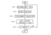
- the main control unit 32 displays the past image stored in the recording medium 41 on the EVFLCD 42 based on the operation of the back operation unit 16 by the user (S11).
- the main control unit 32 displays a plurality of past images on the EVFLCD 42, and selects one past image selected based on the operation of the back operation unit 16 by the user. Display an image.
- the display format for displaying a plurality of past images on the EVFLCD 42 may be a list display such as thumbnails, or a display format for switching images one by one based on an input operation of the back operation unit 16 by the user.
- the first area designating unit 76 designates the first designated area in one past image displayed on the EVFLCD 42 based on the operation of the rear operation unit 16 by the user (S12).
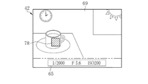
- the first color temperature acquisition unit 71 acquires the color temperature in the first designated area as the target color temperature. (S13). For example, as shown in FIG. 7, a past image 69 obtained by photographing an indoor landscape is displayed on the EVF LCD 42, and the first designated area 78 is designated according to a white cup placed on the table.
- the target color temperature acquired by the first color temperature acquisition unit 71 is, for example, 5000K (Kelvin).
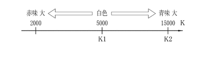
- the target color temperature storage unit 72 stores the target color temperature acquired by the first color temperature acquisition unit 71 (S14). As described above, when the color temperature of the first designated area 78 acquired by the first color temperature acquisition unit 71 is 5000K, the target color temperature storage unit 72 sets 5000K to the target color as shown in FIG. Store as temperature “K1”. The correspondence between color temperature and color is as shown in FIG. 5000K corresponds to almost pure white, and there is a relationship that the higher the color temperature, the greater the blueness, and the lower the color temperature, the greater the redness.
- the main control unit 32 ends the target color temperature information setting mode when the operation for ending the target color temperature information setting mode is performed (YES in S15). On the other hand, when the end operation of the target color temperature information setting mode is not performed (NO in S15), the main control unit 32 executes selection and display (S11) of the past image, so that a plurality of target color temperatures are obtained. It can be stored in the target color temperature storage unit 72.
- the first designated area can be designated according to the blue sky outside the window (S12).
- the color temperature acquired by the first color temperature acquisition unit 71 is, for example, 15000K.
- the target color temperature storage unit 72 stores 15000K acquired by the first color temperature acquisition unit 71 as the target color temperature “K2” (see FIG. 8).
- the target color temperature “K2” is stored in the target color temperature storage unit 72 in addition to the target color temperature “K1”.
- the user can register an ideal reference color of a photographed image desired to be obtained by photographing from a previously photographed image as a target color temperature in advance before photographing.
- the second color temperature obtaining unit 73 obtains the second color temperature in the acquired captured image.
- the color temperature in the area corresponding to the designated area is acquired as the image color temperature (S22).
- the image color temperature acquired by the second color temperature acquisition unit 73 is, for example, 4000K.
- the main control unit 32 grasps the correspondence between the color temperature and the color, and based on this correspondence, obtains a color corresponding to the image color temperature acquired by the second color temperature acquisition unit 73 and obtains the color.
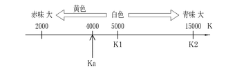
- the color is displayed in the image color temperature information display area 62 of the EVFLCD 42 (S23). As described above, when the image color temperature is “4000K”, the image color temperature information display area 62 displays a slightly yellowish white color.
- the main control unit 32 acquires the target color temperature from the target color temperature storage unit 72 based on the image color temperature acquired by the second color temperature acquisition unit 73 (S24). For example, as shown in FIG. 11, when two target color temperatures K 1 and K 2 are stored in the target color temperature storage unit 72, the main control unit 32 is acquired by the second color temperature acquisition unit 73. A target color temperature K1 having a small difference from the image color temperature Ka is selected and acquired.
- the main control unit 32 obtains a color corresponding to the acquired target color temperature K1, and displays the obtained color in the target color temperature information display area 63 of the EVFLCD 42 (S25). As described above, when the target color temperature K1 is “5000K”, the target color temperature information display area 63 displays substantially pure white.
- the user compares the colors displayed in the image color temperature information display area 62 and the target color temperature information display area 63 and changes the display color of the image color temperature information display area 62 to the display color of the target color temperature information display area 63.
- the color temperature of the captured image is adjusted by performing a color temperature adjustment operation using the control ring 13a so as to be close to.
- the main control unit 32 detects the color temperature adjustment operation amount by the user, that is, the rotation amount of the control ring 13a (S26).
- the color temperature adjustment unit 74 obtains a color temperature shift amount corresponding to the rotation amount acquired from the main control unit 32.
- the color temperature adjustment unit 74 outputs and sets the obtained shift amount to the digital signal processing unit 35 (S27). Thereby, the color temperature adjustment according to the shift amount is executed by the digital signal processing unit 35 on the captured image acquired in step S22 in the next imaging cycle.
- Steps S21 to S27 are repeatedly executed until the photographing operation by the user pressing the release button 14b is executed (YES in S28). Accordingly, the display color of the image color temperature information display area 62 is changed in conjunction with the color temperature adjustment operation by the user.
- the user compares the display color of the image color temperature information display area 62 with the display color of the target color temperature information display area 63, and executes the shooting operation when the display colors of the two substantially match.
- photographing operation is performed (YES in S28)
- photographing is performed (S29)
- a photographed image in which the color temperature is adjusted via the digital signal processing unit 35 is recorded on the recording medium 41.
- the digital camera 11 configured as described above will be described.
- the power button 14a is operated by the user and the still image capturing mode is selected as the operation mode
- the digital camera 11 repeatedly captures an optical image and periodically acquires captured images.
- the finder mode can be selected.
- the finder mode is set to a color temperature adjustment mode which is a kind of OVF mode
- the user can adjust the color temperature of the captured image by the control ring 13a.
- the color of the image color temperature corresponding to the second designated area in the captured image is displayed in the image color temperature information display area 62. Is displayed.
- the target color temperature information display area 63 the color of the target color temperature preset in the target color temperature information setting mode is displayed.
- the color of the image color temperature representing the color of the captured image is displayed in the image color temperature information display area 62, and the target color temperature information display area 63 adjacent thereto is displayed in the target color temperature information setting mode. Since the color of the preset target color temperature is displayed, the color of the captured image can be brought close to the ideal color with high accuracy.
- the target color temperature information is acquired by designating the first designated area in the past image acquired by past shooting, but the target image for acquiring the target color temperature is the digital camera 11. It is not limited to past images taken in the past. For example, an image existing in a database on the Internet is captured in the recording medium 41 and / or captured in the digital camera 11 via a wired or wireless communication unit (not shown). The image may be the target image.
- the target image may be a captured image obtained before the release button 14b is pressed.
- the captured image is displayed as a live view image, and target color temperature information is acquired from the first designated area designated in the live view image.
- a target color temperature is acquired using a color chart in which colors having different color temperatures are arranged instead of a past image as a target image.
- a color chart 81 shown in FIG. 12 is stored in advance in the memory 40 serving as an image storage unit.
- colors having different color temperatures are sequentially arranged according to the color temperatures.
- the main control unit 32 displays the color chart 81 on the EVFLCD 42. In the present embodiment, only a part of the entire area of the color chart 81 is displayed. In FIG. 12, only the range of 3000K to 7000K is displayed. The display range of the color chart 81 can be changed based on the operation of the back operation unit 16.
- An index 83 is displayed adjacent to the upper side of the color chart 81.
- a linear area 84 indicated by the index 83 corresponds to the first designated area of the first embodiment.
- the first designated area is displayed so as to be identifiable with respect to the color chart 81.
- the user can change the first designated area by operating the back operation unit 16 and changing the display range of the color chart 81.
- the user operates the back surface operation unit 16 to designate and determine a desired first designated region in the color chart 81, so that the first color temperature acquisition unit 71 sets the color temperature of the first designated region to the target. Obtained as the color temperature.
- the user in the color temperature information setting mode, can register the target color temperature in the target color temperature storage unit 72 by selecting the first designated area.
- the color temperature may be set (preset) in the target color temperature storage unit 72.
- the user may be able to perform an editing operation such as deletion or change of the target color temperature registered in the target color temperature storage unit 72. It is also preferable that the target color temperature setting operation can be executed for each type of shooting scene.
- the designation of the first designated area is performed in the past image based on the operation of the back operation unit 16 by the user.
- the designation of the first designated area can be automated.
- the first designated area is automatically designated from the past image according to the color targeted by the user.
- the main control unit 32 causes the EVFLCD 42 to display a selection screen for selecting one of a plurality of colors such as white, red, and blue.
- the user can set a target color by operating the back operation unit 16.
- the first region specifying unit 76 extracts a region similar to the color set by the main control unit 32 from the past image 69, and sets the extracted region as the first specified region. For example, when white is set as the target, the first area designating unit 76 extracts pixels including pixel values close to white from the past image 69. The first area designating unit 76 sets an area where the extracted pixels are dense as a first designated area.
- the first area designating unit 76 extracts an area corresponding to the white cup, and sets the extracted area as the first designated area 85.
- the first color temperature acquisition unit 71 acquires the color temperature of the average color in the first designated area 85 as the target color temperature.
- the main control unit 32 causes the user to recognize which region is designated as the first designated region by highlighting the region extracted by the first region designating unit 76 with blinking display or the like.
- the first region designating unit 76 sets the region having the largest area as the first designated region.
- a plurality of regions similar to the color set by the main control unit 32 exist in a discrete manner, it may be possible for the user to select which region is the first designated region.
- the designation of the second designated area can be automated in the same way.
- the second area designating unit 77 extracts a color area similar to the color corresponding to the target color temperature from the captured image, and designates the second designated area in the optical image based on the extracted area. .
- the second region designating unit 77 obtains the optical image 64 by capturing it. A pixel including a pixel value close to white is extracted from the captured image. The second area designating unit 77 designates the area of the optical image 64 corresponding to the extracted area as the second designated area 86. The second color temperature acquisition unit 73 acquires the color temperature of the average color in the second designated area 86 as the image color temperature.
- the main control unit 32 causes the user to recognize which region is designated as the second designated region by highlighting the region extracted by the second region designating unit 77 with blinking display or the like.
- the second area designating unit 77 may set the area having the largest area as the second designated area when there are a plurality of discrete areas having colors close to the color corresponding to the target color temperature. In addition, when a plurality of color regions close to the color corresponding to the target color temperature exist in a discrete manner, it may be possible for the user to select which region is the second designated region.
- the target color temperature information and the image color temperature information are displayed by the color of each color temperature.
- the present invention is not limited to this, and may be displayed by a numerical value representing each color temperature.
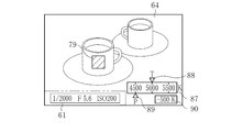
- the target color temperature information and the image color temperature information are represented by the positions of the first index 88 and the second index 89 with respect to the color temperature scale 87.
- a symbol “T” is displayed in the vicinity of the first index 88 and in the vicinity of the second index 89.
- the symbol “P” is displayed.
- the color temperature scale 87 indicates an area of 4500K or more and 5500K or less.
- the first index 88 is displayed at a position corresponding to the target color temperature acquired by the first color temperature acquisition unit 71.
- the second index 89 is displayed at a position corresponding to the image color temperature acquired by the second color temperature acquisition unit 73.
- Other configurations of the fourth embodiment are the same as those of any of the first to third embodiments.
- the main control unit 32 calculates the color temperature difference between the target color temperature and the image color temperature, and as shown in FIG.
- color temperature difference information 90 representing the color temperature difference may be displayed.
- the main control unit 32 functions as a color temperature difference calculation unit.
- the image color temperature information and the target color temperature information are superimposed and displayed on the optical image.
- the temperature information 66 and the target color temperature information 67 may be displayed close to each other.
- the image color temperature information 66 and the target color temperature information 67 can be partially superimposed on the optical image 64 as shown in FIG.
- Step S22 and Step S23 for acquiring and displaying the image color temperature are performed for each imaging cycle, but the present invention is not limited to this, and two or more specific imaging cycles are performed. You may go every time. Moreover, although step S24 and step S25 which acquire and display target color temperature are performed for every imaging cycle, it is not restricted to this, You may perform for every 2 or more specific imaging cycles.
- step S24 is executed in which the target color temperature close to the image color temperature is acquired from the target color temperature storage unit 72.
- the step S24 may be configured not to be executed during the color temperature adjustment mode. That is, the target color temperature used in the color temperature adjustment mode may be selectable by the user before entering the color temperature adjustment mode.
- step S26 and step S27 for performing the setting process of the color temperature shift amount based on the color temperature adjustment operation are performed for each imaging cycle. It may be performed every two or more specific imaging cycles.
- the second color temperature acquisition unit 73 acquires the image color temperature from the YC image data generated by the digital signal processing unit 35, but the image color from the RGB format image data before the YC conversion process. You may acquire temperature.
- the digital signal processing unit 35 may be provided with an auto white balance (AWB) adjustment processing function.
- AVB auto white balance
- manual color temperature adjustment is performed on the image data after the AWB adjustment processing.
- the type of the light source may be erroneously detected depending on the shooting scene. Even in such a case, the user can adjust the color temperature with high accuracy.
- the digital signal processing unit 35 is provided separately from the image sensor 31, but can be incorporated in the image sensor 31.
Landscapes
- Engineering & Computer Science (AREA)
- Multimedia (AREA)
- Signal Processing (AREA)
- Physics & Mathematics (AREA)
- General Physics & Mathematics (AREA)
- Human Computer Interaction (AREA)
- Studio Devices (AREA)
- Color Television Image Signal Generators (AREA)
- Indication In Cameras, And Counting Of Exposures (AREA)
Abstract
画像の色温度を精度良く調整することを可能とする撮影装置及びその制御方法を提供する。 撮像素子(31)は、撮影レンズ(18)を介して入射する光学像(64)を撮像する。ファインダ装置(17)は、光学像(64)を観察可能に構成されている。EVFLCD(42)は、ファインダ装置(17)内において、光学像(64)に情報を重畳又は近接させて観察可能に表示させる。EVF表示制御部(39)は、EVFLCD(42)を制御して、情報として、色温度調整の目標とする色温度を表す目標色温度情報(67)と、撮像画像の色温度を表す画像色温度情報(66)とを表示させる。色温度調整部(74)は、色温度の調整操作に基づき、撮像素子(31)により光学像(64)を撮像して得られた撮像画像の色温度を調整する。色温度の調整操作が行われると、調整操作量に応じて画像色温度情報(66)が変更される。
Description
本発明は、ハイブリッドビューファインダを有する撮影装置及びその制御方法に関する。
近年、ハイブリッドビューファインダを有するデジタルカメラなどの撮影装置が知られている(特許文献1,2参照)。ハイブリッドビューファインダは、被写体の光学像と、この光学像を撮像素子で撮像して得られた被写体の撮像画像とのうちの一方または両方をファインダ部内に表示可能とするものである。特に、ハイブリッドビューファインダでは、光学像に撮像画像を重畳又は近接させて表示させることを可能とする。このハイブリッドビューファインダにより、ユーザは、撮影により得られる画像を事前に確認しながら、光学像により被写体のフレーミングを行うことができる。
デジタルカメラは、オートホワイトバランス(AWB)調整機能を有しているものが多い。AWB調整機能は、撮影時に光源の種類(太陽、蛍光灯、白熱電球など)を検出し、白い被写体が白く撮影されるように、画像の色味を表す色温度を自動調整する機能である。しかし、AWB調整機能では、撮影シーンによっては、光源の種類を誤検出することなどにより、色温度の調整が不適切に行われることがある。例えば、森のように緑色が多く含まれている撮影シーンでは、光源の種類が「太陽」と検出されるべきところ、「蛍光灯」と誤検出されることがある。
このような事情から、特許文献2に記載の撮影装置では、ハイブリッドビューファインダモードにおいて、ユーザが光学像と撮像画像との両者の色味を比較しながら、撮像画像の色温度の調整を手動で行うことが可能とされている。
しかしながら、特許文献2に記載の撮影装置のように、ハイブリッドビューファインダモードにおいてユーザが光学像の色を目標として撮像画像の色温度の調整を行う場合には、目標とする光学像の色が実際の理想的な色から多少ずれていたとしても、ユーザは色がずれていることを認識できず理想的な色であると誤認識してしまうことがある。これは、我々人間が脳内で無意識のうちに色味の補正を行っていることによる。
例えば白熱電球のように赤味がかった(色温度が低い)光源下では、白色の用紙はやや黄色味がかった色となるが、ユーザは理想的な白色であると誤認識することがある。このように、特許文献2に記載の撮影装置では、目標とする光学像の色が理想的な色からずれている場合においても、ユーザの誤認識により理想的な色からずれた色が目標とされて撮像画像の色温度の調整が行われる。この結果、撮像画像の色温度の調整が精度良く行われない。
したがって、特許文献2に記載の撮影装置では、光学像を色温度の調整の目標とする結果、光源種などの差異により画像の色温度の調整が精度良く行われず、撮影により得られる画像の色味にばらつきが生じるという問題がある。これは、AWB調整機能の有無にかかわらず生じる問題である。
本発明は、画像の色温度を精度良く調整することを可能とする撮影装置及びその制御方法を提供することを目的とする。
上記目的を達成するため、本発明の撮影装置は、撮像素子と、ファインダ部と、ファインダ内情報表示部と、色温度調整部と、目標色温度情報と、表示制御部と、を備える。撮像素子は、撮影レンズを介して入射する光学像に基づき画像を生成する。ファインダ部は、光学像を観察可能に構成されている。ファインダ内情報表示部は、ファインダ部内において、光学像に情報を重畳又は近接させて観察可能に表示させる。色温度調整部は、色温度の調整操作に基づき、画像の色温度を調整する。目標色温度情報は、ファインダ内情報表示部を制御して、情報として、色温度の調整の目標とする色温度を表す。表示制御部は、画像の色温度を表す画像色温度情報とを表示させる。
表示制御部は、色温度の調整操作が行われた場合に、色温度調整部により色温度が調整された後の画像の画像色温度情報を表示させることが好ましい。
画像記憶部と、画像記憶部に記憶されている記憶画像中に第1指定領域を指定する第1領域指定部と、第1領域指定部により指定された第1指定領域の色温度を取得する第1色温度取得部と、を備え、目標色温度情報は、第1色温度取得部により取得された第1指定領域の色温度を表すことが好ましい。
記憶画像は、撮影により得られた画像であることが好ましい。
記憶画像は、異なる色温度の色が配列されたカラーチャートであっても良い。
第1指定領域は、カラーチャートに対して識別可能に表示されることが好ましい。
第1色温度取得部は、第1指定領域内の平均の色温度を算出することが好ましい。
ファインダ部内で観察される光学像中に第2指定領域を指定する第2領域指定部と、第2領域指定部により指定された第2指定領域に対応する画像の色温度を取得する第2色温度取得部と、を備え、画像色温度情報は、第2指定領域に対応する画像の色温度を表すことが好ましい。
第2色温度取得部は、第2指定領域内の平均の色温度を算出することが好ましい。
第1指定領域の色温度と第2指定領域の色温度との色温度差を算出する色温度差算出部を備え、表示制御部は、情報として、目標色温度情報と画像色温度情報に加え、色温度差を表す色温度差情報を表示させることが好ましい。
表示制御部は、ファインダ内情報表示部を制御して、第1エリアと第2エリアとを互いに隣接して設定し、画像色温度情報によって表される色温度の色を第1エリアに表示させ、目標色温度情報によって表される色温度の色を第2エリアに表示させることが好ましい。
ファインダ部内において、光学像を部分的に遮光可能とする遮光部を有し、ファインダ内情報表示部は、情報を、遮光部により部分的に遮光された部分に第1エリア及び第2エリアを設定することが好ましい。
本発明の撮影装置の制御方法は、撮影レンズを介して入射する光学像に基づき画像を生成する撮像素子と、光学像を観察可能に構成されたファインダ部と、ファインダ部内において、光学像に情報を重畳又は近接させて観察可能に表示させるファインダ内情報表示部と、色温度の調整操作に基づき、画像の色温度を調整する色温度調整部と、を備える撮影装置の制御方法において、ファインダ内情報表示部を制御して、情報として、色温度の調整の目標とする色温度を表す目標色温度情報と、画像の色温度を表す画像色温度情報とを表示させる。
本発明の撮影装置及びその制御方法によれば、色温度の調整の目標とする色温度を表す目標色温度情報と、画像の色温度を表す画像色温度情報とを、光学像に重畳又は近接させて観察可能に表示させるので、画像の色温度を精度良く調整することができる。
[第1実施形態]
図1及び図2において、撮影装置としてのデジタルカメラ11は、カメラ本体12、レンズ鏡筒13、上面操作部14、背面表示部15、背面操作部16、及びファインダ装置(ファインダ部)17を備える。
図1及び図2において、撮影装置としてのデジタルカメラ11は、カメラ本体12、レンズ鏡筒13、上面操作部14、背面表示部15、背面操作部16、及びファインダ装置(ファインダ部)17を備える。
ファインダ装置17は、光学ビューファインダ(OVF;Optical View Finder)モード(以下、OVFモードという)と、電子ビューファインダ(EVF;Electronic View Finder)モード(以下、EVFモードという)と、ハイブリッドビューファインダ(HVF;Hybrid View Finder)モード(以下、HVFモードという)との間でのモード切り替えが可能である。
OVFモードでは、被写体の光学像と、撮影条件などの電子情報を表す情報画像とが重ね合わせられたOVF画像を観察可能とする。EVFモードでは、光学像を撮像して得た撮像画像及び情報画像を観察可能とする。HVFモードは、光学像と撮像画像の両方を観察可能とする。
OVFモードには、撮像画像の色温度をユーザが手動で調整可能とする色温度調整モードが含まれる。この色温度調整モードでは、電子情報として、撮像画像の色温度を表す画像色温度情報と、色温度の調整の目標とする色温度を表す目標色温度情報とが表示される。
また、デジタルカメラ11には、ユーザが目標色温度情報を設定するための目標色温度情報設定モードが設けられている。目標色温度情報設定モードは、ユーザが撮影により得たい撮影画像の理想の基準色を撮影前に事前に登録するモードである。色温度調整モードや目標色温度情報設定モードへの切り替えは、上面操作部14の操作により行われ、後述する主制御部32により実行される。
レンズ鏡筒13は、カメラ本体12の前面に設けられており、撮影レンズ18を保持している。レンズ鏡筒13には、コントロールリング13aが設けられている。コントロールリング13aは、レンズ鏡筒13に対して、撮影レンズ18の光軸を中心として回転可能に取り付けられている。コントロールリング13aは、設定の切り替えなど各種操作に用いられ、色温度調整モードではユーザによる色温度調整操作に用いられる。
コントロールリング13aの回転量は、色温度の調整操作量(色温度のシフト量)に対応している。後述する主制御部32は、コントロールリング13aの回転位置を、位置センサ(図示せず)を介して検出し、基準位置からの回転量を求める。後述する色温度調整部74は、主制御部32により求められた回転量に対応する色温度のシフト量を求める。
上面操作部14は、カメラ本体12の上面に設けられており、電源ボタン14a、レリーズボタン14b、モード切替ダイヤル14c、ファインダ切替レバー14dなどを含む。電源ボタン14aは、デジタルカメラ11の電源(図示せず)をオンまたはオフする際に操作される。レリーズボタン14bは、撮影を実行する際に操作される。モード切替ダイヤル14cは、撮影モード、画像再生モード、設定モードなどの間で動作モードを切り替える際に操作される。モード切替ダイヤル14cは、前述の色温度調整モードおよび目標色温度情報設定モードの設定操作にも用いられる。ファインダ切替レバー14dは、ファインダ装置17のモードを、OVFモードとEVFモードとHVFモードとの間でファインダのモードを切り替える際に操作される。
撮影モードには、静止画像を取得する静止画撮影モードと、動画像を取得する動画撮影モードとがある。画像再生モードでは、静止画撮影モードまたは動画撮影モードで取得された画像が、背面表示部15に再生表示される。
レリーズボタン14bは、S1スイッチとS2スイッチとで構成された2段ストローク式のスイッチ(図示せず)を有する。デジタルカメラ11は、レリーズボタン14bが押下(半押し)され、S1スイッチがオン状態となると、オートフォーカス(AF)動作などの撮影準備動作を行う。この状態からさらにレリーズボタン14bが押下(全押し)され、S2スイッチがオン状態となると、デジタルカメラ11は撮影動作を行う。
背面表示部15は、カメラ本体12の背面に設けられており、各種撮影モードで取得された撮影画像や、各種設定を行うためのメニュー画面などを表示する。なお、背面表示部15は、LCD(Liquid Crystal Display)などの表示装置とタッチパッドなどの入力装置を組み合わせたタッチスクリーンであってもよい。この場合、タッチスクリーンに対するタッチ操作により各種設定を行うことができる。
背面操作部16は、カメラ本体12の背面に設けられている。背面操作部16は、各種設定操作の他に、目標色温度情報設定モードにおいてユーザが目標色温度情報を設定する際に用いられる。
ファインダ装置17は、被写体の光学像を取り込むファインダ窓17aと、ユーザの眼が接眼されるファインダ接眼部17bとを有している。ファインダ窓17aは、カメラ本体12の前面側に設けられている。ファインダ接眼部17bは、カメラ本体12の背面側に設けられている。
また、カメラ本体12の底部には、後述する記録メディア41(図3参照)を装着するためのスロット(図示せず)が設けられている。
図3において、レンズ鏡筒13内には、絞り30と撮像素子31とが撮影レンズ18の光軸LAに沿って設けられている。絞り30は、主制御部32によって駆動制御され、撮像素子31に入射させる光量を調整する。撮像素子31には、撮影レンズ18を通過し、絞り30により光量が調整された被写体の光学像が入射する。なお、撮像素子31は、レンズ鏡筒13外に配置されていても良い。
撮影レンズ18は、ズームレンズ18a及びフォーカスレンズ18bを含む。撮影レンズ18には、レンズ駆動部24が接続されている。レンズ駆動部24は、主制御部32の制御の下、ズームレンズ18a及びフォーカスレンズ18bを光軸方向に移動させる。ズームレンズ18aの駆動によりズーミングが行われ、フォーカスレンズ18bの駆動によりAF動作が行われる。
撮像素子31は、例えば、RGB方式のカラーフィルタを有する単板カラー撮像方式のCMOS(Complementary Metal Oxide Semiconductor)型イメージセンサである。撮像素子31は、2次元マトリクス状に配列された複数の画素(図示せず)により構成された受光面を有している。各画素は、光電変換素子を含んでおり、受光面に結像された光学像を光電変換により撮像して撮像信号を生成する。また、撮像素子31は、電子シャッタ機能を有しており、シャッタ速度(電荷蓄積時間)が調整可能である。
撮像素子31は、信号処理回路を備えている。信号処理回路としては、ノイズ除去回路、オートゲインコントローラ、A/D(Analog/Digital)変換回路などがある(いずれも図示せず)。ノイズ除去回路は、撮像信号にノイズ除去処理を施す。オートゲインコントローラは、撮像信号のレベルを最適な値に増幅する。A/D変換回路は、撮像信号をデジタル信号に変換して撮像素子31から出力する。撮像素子31の出力信号は、画素ごとに1つの色信号を有するRGB形式の画像データ(いわゆるRAWデータ)である。
撮像素子31及び主制御部32は、バス33に接続されている。この他、バス33には、メモリ制御部34、デジタル信号処理部35、目標色温度設定処理部36a、色温度調整処理部36b、メディア制御部37、背面表示制御部38、及びEVF表示制御部(表示制御部)39が接続されている。
メモリ制御部34には、SDRAM(Synchronous Dynamic Random Access Memory)などの一時記憶用のメモリ40が接続されている。メモリ制御部34は、撮像素子31から出力されたRGB形式の画像データをメモリ40に入力して記憶させる。また、メモリ制御部34は、メモリ40に記憶されたRGB形式の画像データを、デジタル信号処理部35に出力する。
デジタル信号処理部35は、メモリ制御部34から入力されたRGB形式の画像データに対して、欠陥補正処理、デモザイク処理、ガンマ補正処理、RGBゲイン補正処理、YC変換処理などを行い、輝度信号Yと色差信号CとからなるYC形式の画像データ(YC画像データ)を生成する。デジタル信号処理部35は、生成したYC形式の画像データを、メモリ制御部34に出力することで、メモリ40に記憶させる。
また、デジタル信号処理部35は、YC画像データに対し、各種撮影モードに応じた圧縮処理を施すことで画像ファイルを生成する。具体的には、デジタル信号処理部35は、静止画撮影モードの場合には、YC画像データを、例えばJPEG(Joint Photographic Experts Group)規格などで圧縮して圧縮画像データを生成する。デジタル信号処理部35は、動画撮影モードの場合には、動画撮影により得られる複数フレームのYC画像データを、例えばMPEG(Moving Picture Experts Group)-4規格などで圧縮した動画データを生成する。デジタル信号処理部35は、生成した画像ファイルをメディア制御部37に出力する。
メディア制御部37は、画像記憶部としての記録メディア41への画像ファイルの記録及び読み出しを制御する。記録メディア41は、例えば、フラッシュメモリなどを内蔵したメモリカードである。静止画撮影モードの場合には、デジタル信号処理部35により生成された圧縮画像データが記録メディア41に記録される。また、動画撮影モードの場合には、デジタル信号処理部35により生成された動画データが記録メディア41に記録される。なお、動画撮影モードの場合には、画像に加えて音声も取得して記録されるが、本実施形態では、音声の取得及び記録に関する構成については、説明を省略する。
目標色温度設定処理部36aは、第1色温度取得部71と目標色温度記憶部72とを有する。色温度調整処理部36bは、第2色温度取得部73と色温度調整部74とを有する。目標色温度設定処理部36aは、目標色温度情報設定モードにおいて作動し、ユーザによる目標色温度の設定を可能とする。色温度調整処理部36bは、色温度調整モードにおいて作動し、撮像画像の色温度の取得と、ユーザの操作に応じた撮像画像の色温度の調整を可能とする。
背面表示制御部38は、背面表示部15への画像表示を制御する。具体的には、背面表示制御部38は、デジタル信号処理部35により生成されたYC画像データに基づいて、NTSC(National Television System Committee)規格などに準拠した映像信号を生成して背面表示部15に出力する。
EVF表示制御部39は、背面表示制御部38と同様にYC画像データに基づいて映像信号を生成し、後述するEVFLCD42に出力する。
ファインダ装置17には、ファインダ内情報表示部としてのEVFLCD42と、プリズム43と、遮光部としてのOVFシャッタ44とが設けられている。
EVFLCD42は、各種撮影モードで取得された各種画像を表示する。EVFLCD42には、ファインダのモードに応じて画像を表示するエリアが設定される。
EVFモードでは、EVFLCD42には、被写体の光学像を撮像素子31により撮像して得た撮像画像が表示される画像表示エリア(図示せず)と、情報画像が表示される情報表示エリア(図示せず)とが設定される。情報表示エリアは、画像表示エリアの周囲、例えば下側に設定される。撮像画像は、デジタル信号処理部35により生成されるYC画像データの表示画像である。情報画像は、主制御部32により生成される情報画像データの表示画像である。情報画像データは、撮影条件などの撮影情報に基づいて生成される。撮影条件には、シャッタ速度、絞り値、ISO感度などが含まれる。撮影条件は、例えば上面操作部14の操作によって設定可能である。
OVFモードでは、EVFLCD42には、情報表示エリアが設定される。情報表示エリアは、EVFモードと同様に、例えば下側に設定される。なお、OVFモードでは、EVFモードにおける画像表示エリアは非表示とされる。
HVFモードでは、EVFLCD42には、情報表示エリアに加えて、撮像画像が表示されるサブ表示エリア(図示せず)が設定される。サブ表示エリアは、例えば、画面右下に情報表示エリアと隣接して設定される。なお、HVFモードでは、EVFモードにおける画像表示エリアは非表示とされる。
OVFモードの一種である色温度調整モードでは、図4に示すように、EVFLCD42には、情報表示エリア61と、画像色温度情報表示エリア(第1エリア)62と、目標色温度情報表示エリア(第2エリア)63とが設定される。なお、その他のエリア(EVFモードにおける画像表示エリア)は、非表示とされる。情報表示エリア61中の「1/2000」はシャッタ速度、「ISO200」はISO感度、「F5.6」は絞り値の表示例である。
画像色温度情報表示エリア62には、撮像画像の色温度を表す画像色温度情報が表示される。本実施形態では、画像色温度情報表示エリア62には、画像色温度情報として、撮像画像の色温度に対応した単一色の画像が表示される。目標色温度情報表示エリア63には、色温度の調整の目標とする色温度を表す目標色温度情報が表示される。本実施形態では、目標色温度情報表示エリア63には、目標色温度情報として、目標色温度に対応した単一色の画像が表示される。画像色温度情報表示エリア62と目標色温度情報表示エリア63とは、互いに隣接して設定されている。例えば、画像色温度情報表示エリア62及び目標色温度情報表示エリア63は、画面右下に情報表示エリア61と隣接して設定されている。
図3において、プリズム43は、光路統合部としてのハーフミラー48が内部に構成されている。ハーフミラー48は、ファインダ窓17aに入射した被写体の光学像が伝搬する第1光路49と、EVFLCD42に表示された表示画像が伝搬する第2光路50とに対して45度の角度をなすように配置されている。このハーフミラー48は、第1光路49と第2光路50とを統合して第3光路51とする。この第3光路51上にファインダ接眼部17bが配置されている。
ハーフミラー48は、第1光路49上を伝搬する光学像を一部透過させて第3光路51に導き、第2光路50上を伝搬する表示画像を一部反射させて第3光路51に導く。これにより、光学像及び表示画像がファインダ接眼部17bに導かれる。
OVFシャッタ44は、液晶シャッタであり、第1光路49上に配置されている。OVFシャッタ44の光透過率は、主制御部32により低透過率(例えば、0%)又は高透過率(例えば、100%)に制御される。OVFシャッタ44は、光透過率が低透過率とされたエリアでは光学像を遮光してプリズム43に入射させないようにし、光透過率が高透過率とされたエリアでは光学像を透過させてプリズム43に入射させる。主制御部32は、EVFLCD42の各表示エリアを把握しており、ファインダのモードに応じて全部又は部分的にOVFシャッタ44の光透過率を変更させる。
EVFモードの場合には、主制御部32は、OVFシャッタ44を制御して、EVFLCD42の画像表示エリアと情報表示エリアに対応するエリアを低透過率とする。この場合、OVFシャッタ44の全部が低透過率となる。低透過率とされたOVFシャッタ44は、光学像を遮光する。EVFLCD42の画像表示エリアには撮像画像が表示され、情報表示エリアには情報画像が表示される。これにより、EVFモードでは、撮像画像及び情報画像がファインダ接眼部17bから観察可能となる。
OVFモードの場合には、主制御部32は、OVFシャッタ44を制御して、EVFLCD42の画像表示エリアに対応するエリアを高透過率とし、情報表示エリアに対応するエリアを低透過率とする。OVFシャッタ44は、画像表示エリアに対応するエリアでは光学像を透過させ、情報表示エリアに対応するエリアでは光学像を非透過とする。EVFLCD42の画像表示エリアは非表示とされ、情報表示エリアには情報画像が表示される。これにより、OVFモードでは、EVFLCD42に表示された情報画像が光学像に重畳されてなるOVF画像が、ファインダ接眼部17bから観察可能となる。
HVFモードの場合には、主制御部32は、OVFシャッタ44を制御して、EVFLCD42の画像表示エリアに対応するエリアを高透過率とし、情報表示エリアとサブ表示エリアに対応するエリアを低透過率とする。OVFシャッタ44は、画像表示エリアに対応するエリアでは光学像を透過させ、情報表示エリアとサブ表示エリアに対応するエリアでは光学像を非透過とする。EVFLCD42の画像表示エリアは非表示とされ、サブ表示エリアには撮像画像が表示され、情報表示エリアには情報画像が表示される。これにより、HVFモードでは、光学像に撮像画像及び情報画像が重畳されたHVF画像がファインダ接眼部17bから観察可能となる。
色温度調整モードの場合には、主制御部32は、OVFシャッタ44を制御して、EVFLCD42の画像表示エリアに対応するエリアを高透過率とし、情報表示エリア61、画像色温度情報表示エリア62、及び目標色温度情報表示エリア63に対応するエリアを低透過率とする。OVFシャッタ44は、画像表示エリアに対応するエリアでは光学像を透過させ、情報表示エリア61、画像色温度情報表示エリア62、及び目標色温度情報表示エリア63に対応するエリアでは光学像を非透過とする。
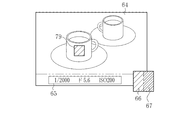
EVFLCD42の画像表示エリアは非表示とされ、情報表示エリア61には情報画像が表示され、画像色温度情報表示エリア62には画像色温度情報が表示され、目標色温度情報表示エリア63には目標色温度情報が表示される。これにより、色温度調整モードでは、図5に示すように、光学像64に、情報画像65と画像色温度情報66と目標色温度情報67とが重畳されたファインダ観察画像68が、ファインダ接眼部17bから観察可能となる。重畳とは、光学像64を一部遮光させ、遮光させた部分に画像や情報を表示させることである。
次に、目標色温度設定処理部36aの詳細について説明する。第1色温度取得部71は、色温度情報設定モード時に、色温度調整の目標とする色温度を表す目標色温度を取得する。具体的には、色温度情報設定モードでは、主制御部32の制御により、画像記憶部としての記録メディア41に記憶されている過去画像(記憶画像)がEVFLCD42に表示される。1つの過去画像中には、第1指定領域が指定される。第1色温度取得部71は、過去画像中の第1指定領域の色温度を求め、求めた色温度を目標色温度として取得する。なお、過去画像は、撮影により得られた画像であり、記録メディア41に限られず、内部メモリであるメモリ40に記憶されていても良い。
さらに具体的には、主制御部32は、第1領域指定部76を有しており、ユーザによる背面操作部16の操作に基づき、1つの過去画像中に第1指定領域を指定可能とする。第1色温度取得部71は、例えば、第1指定領域の平均色を求め、求めた平均色の色温度を目標色温度として取得する。平均色は、第1指定領域中のR信号、G信号、B信号の各平均値の比率に対応する。なお、第1領域指定部76により第1指定領域の指定を複数回行うことが可能とされている。第1色温度取得部71は、第1指定領域の指定が行われる毎に目標色温度を取得する。
目標色温度記憶部72は、第1色温度取得部71により取得された目標色温度を記憶する。なお、第1色温度取得部71により複数の目標色温度が取得された場合には、目標色温度記憶部72は、取得された複数の目標色温度を記憶する。
次に、色温度調整処理部36bの詳細について説明する。第2色温度取得部73は、色温度調整モード時に、撮像画像の色温度を表す画像色温度を取得する。具体的には、色温度調整モードでは、光学像の表示エリア中に第2指定領域が指定される。第2色温度取得部73は、撮像画像中において第2指定領域に対応する領域の色温度を求め、求めた色温度を画像色温度として取得する。
さらに具体的には、主制御部32は第2領域指定部77を有しており、ユーザによる背面操作部16の操作に基づき、光学像中に第2指定領域を指定可能とする。第2色温度取得部73は、デジタル信号処理部35が生成したYC画像データ中において第2指定領域に対応する領域の例えば平均色を求め、求めた平均色の色温度を画像色温度として取得する。第2色温度取得部73は、取得した画像色温度に基づく画像色温度情報を主制御部32に出力する。なお、第2色温度取得部73による色温度の算出方法は、第1色温度取得部71による前述の方法と同様である。
主制御部32は、第2色温度取得部73から画像色温度情報が入力されると、EVF表示制御部39を制御して、EVFLCD42の画像色温度情報表示エリア62に画像色温度情報を表示させる。
また、主制御部32は、第2色温度取得部73から入力された画像色温度情報に基づき、目標色温度記憶部72から目標色温度を取得する。具体的には、主制御部32は、目標色温度記憶部72に記憶されている複数の目標色温度のうち、第2色温度取得部73から入力された画像色温度に近い目標色温度を選択して取得する。そして、主制御部32は、EVF表示制御部39を制御して、EVFLCD42の目標色温度情報表示エリア63に目標色温度に基づく目標色温度情報を表示させる。
色温度調整部74は、色温度の調整操作に基づき、デジタル信号処理部35により生成される撮像画像の色温度を調整する。具体的には、色温度調整部74は、主制御部32により検出されるコントロールリング13aの回転量に基づき、色温度の調整量(シフト量)を求める。色温度調整部74は、求めた色温度のシフト量をデジタル信号処理部35に出力することで、撮像画像に対し、シフト量に応じた色温度調整を実行させる。デジタル信号処理部35は、RGBゲイン補正処理時に、色温度調整部74から入力されたシフト量に基づいて、R信号、G信号、B信号に対する各ゲイン量を変更する。これにより、デジタル信号処理部35により生成される撮像画像の色温度が、ユーザが意図するシフト量に対応して調整される。主制御部32は、EVF表示制御部39を制御して、色温度が調整された後の撮像画像から得られた画像色温度情報を、画像色温度情報表示エリア62に表示させる。
次に、目標色温度情報設定モードについて、図6~図8を参照しながら説明する。目標色温度情報設定モードに入ると、主制御部32は、ユーザによる背面操作部16の操作に基づき、記録メディア41に記憶されている過去画像をEVFLCD42に表示させる(S11)。なお、記録メディア41に複数の過去画像が記憶されている場合は、主制御部32は、複数の過去画像をEVFLCD42に表示させ、ユーザによる背面操作部16の操作に基づき選択された1つの過去画像を表示させる。EVFLCD42に複数の過去画像を表示させる表示形式は、サムネイルのような一覧表示としても良いし、ユーザによる背面操作部16の入力操作に基づき画像を1つずつ切り替える表示形式としても良い。
第1領域指定部76は、ユーザによる背面操作部16の操作に基づき、EVFLCD42に表示された1つの過去画像中に第1指定領域を指定する(S12)。第1色温度取得部71は、第1指定領域内の色温度を、目標色温度として取得する。(S13)。例えば、図7に示すように、屋内の風景を撮影した過去画像69がEVFLCD42に表示され、テーブル上に置かれている白いカップに合わせて第1指定領域78が指定される。この場合、第1色温度取得部71により取得される目標色温度は、例えば、5000K(ケルビン)である。
目標色温度記憶部72は、第1色温度取得部71により取得された目標色温度を記憶する(S14)。上記のように第1色温度取得部71が取得した第1指定領域78の色温度が5000Kであった場合には、目標色温度記憶部72は、図8に示すように、5000Kを目標色温度「K1」として記憶する。色温度と色との対応関係は同図に示す通りである。5000Kはほぼ純粋な白色に対応し、色温度が高いほど青味が増し、色温度が低いほど赤味が増すという関係にある。
主制御部32は、目標色温度情報設定モードの終了操作が行われると、目標色温度情報設定モードを終了させる(S15でYES)。一方、目標色温度情報設定モードの終了操作が行われない場合は(S15でNO)、主制御部32により過去画像の選択及び表示(S11)が実行されることにより、複数の目標色温度を目標色温度記憶部72に記憶することができる。
例えば、図7に示す白いカップの他に、窓の外の青空に合わせて第1指定領域を指定することができる(S12)。この場合、第1色温度取得部71により取得される色温度は、例えば15000Kである。目標色温度記憶部72は、第1色温度取得部71により取得された15000Kを目標色温度「K2」として記憶する(図8参照)。これにより、目標色温度記憶部72には、目標色温度「K1」の他に、目標色温度「K2」が記憶される。
ユーザは、目標色温度情報設定モードにより、過去に撮影した画像から、撮影により得たい撮影画像の理想の基準色を目標色温度として、撮影前に事前に登録することができる。
次に、色温度調整モードについて、図9~図11を参照しながら説明する。色温度調整モードに入ると、撮像素子31により被写体の光学像が撮像され、この撮像により得られた画像データに対してデジタル信号処理部35が各種処理を施すことにより、撮像画像が取得される(S21)。
ユーザによる背面操作部16の操作に基づき、第2領域指定部77が光学像の表示エリア中に第2指定領域を指定すると、第2色温度取得部73は、取得した撮像画像中の第2指定領域に対応する領域内の色温度を画像色温度として取得する(S22)。例えば、図10に示すように、屋内の風景を撮影する撮影シーンにおいて、背面操作部16の操作に基づき、光学像64の白いカップに合わせて第2指定領域79が指定される。この場合、第2色温度取得部73により取得される画像色温度は、例えば、4000Kである。
主制御部32は、色温度と色との対応関係を把握しており、この対応関係に基づいて、第2色温度取得部73により取得された画像色温度に対応する色を求め、求めた色をEVFLCD42の画像色温度情報表示エリア62に表示させる(S23)。上記のように画像色温度が「4000K」の場合には、画像色温度情報表示エリア62には、やや黄色味がかった白色が表示される。
また、主制御部32は、第2色温度取得部73により取得された画像色温度に基づき、目標色温度記憶部72から目標色温度を取得する(S24)。例えば、図11に示すように、目標色温度記憶部72に2つの目標色温度K1,K2が記憶されている場合には、主制御部32は、第2色温度取得部73により取得された画像色温度Kaとの差が小さい目標色温度K1を選択して取得する。
主制御部32は、取得した目標色温度K1に対応する色を求め、求めた色をEVFLCD42の目標色温度情報表示エリア63に表示させる(S25)。上記のように目標色温度K1が「5000K」の場合には、目標色温度情報表示エリア63には、ほぼ純粋な白色が表示される。
ユーザは、画像色温度情報表示エリア62と目標色温度情報表示エリア63とに表示された色を比較し、画像色温度情報表示エリア62の表示色を、目標色温度情報表示エリア63の表示色に近づけるようにコントロールリング13aを用いて色温度調整操作を行うことで、撮像画像の色温度を調整する。
主制御部32は、ユーザによる色温度の調整操作量、すなわちコントロールリング13aの回転量を検出する(S26)。色温度調整部74は、主制御部32から取得した回転量に対応する色温度のシフト量を求める。色温度調整部74は、求めたシフト量を、デジタル信号処理部35に出力して設定させる(S27)。これにより、次の撮像周期においてステップS22で取得される撮像画像に対して、デジタル信号処理部35によりシフト量に応じた色温度調整が実行される。
ステップS21~S27は、ユーザがレリーズボタン14bを押下することによる撮影操作が実行される(S28でYES)までの間、繰り返し実行される。これにより、ユーザによる色温度の調整操作に連動して、画像色温度情報表示エリア62の表示色が変更される。
ユーザは、画像色温度情報表示エリア62の表示色と、目標色温度情報表示エリア63の表示色とを比較しながら、両者の表示色がほぼ一致したときに撮影操作を実行する。この撮影操作が行われると(S28でYES)、撮影が実行され(S29)、デジタル信号処理部35を介して色温度の調整が行われた撮影画像が記録メディア41に記録される。
以上のように構成されたデジタルカメラ11の作用について説明する。デジタルカメラ11は、ユーザにより電源ボタン14aが操作され、動作モードとして静止画撮影モードが選択されると、光学像の撮像を繰り返し行い、撮像画像を周期的に取得する。静止画撮影モードでは、ファインダのモードが選択可能となる。ファインダのモードがOVFモードの一種である色温度調整モードに設定されると、ユーザは、コントロールリング13aにより撮像画像の色温度を調整することが可能となる。
色温度調整モードにおいて、ユーザにより光学像の表示エリア中に第2指定領域が指定されると、撮像画像中の第2指定領域に対応する画像色温度の色が画像色温度情報表示エリア62に表示される。また、目標色温度情報表示エリア63には、目標色温度情報設定モードで予め設定された目標色温度の色が表示される。
ユーザは、撮像画像の色を光学像中の色を目標として合わせようとすると、目標とする光学像中の色が実際の理想的な色から多少ずれていたとしても脳内で無意識のうちに色補正して理想的な色であると誤認識し、この色に撮像画像の色を合わせてしまう。しかし、本実施形態では、撮像画像の色を表す画像色温度の色が画像色温度情報表示エリア62に表示され、これに隣接した目標色温度情報表示エリア63に、目標色温度情報設定モードで予め設定された目標色温度の色が表示されるので、撮像画像の色を理想的な色に精度良く近づけることができる。
上記第1実施形態では、過去の撮影により取得された過去画像中に第1指定領域を指定して目標色温度情報を取得しているが、目標色温度を取得する対象画像は、デジタルカメラ11で過去に撮影された過去画像に限られない。例えば、インターネット上のデータベースなどに存在する画像を、記録メディア41内に取り込む、および/または、有線または無線の通信部(図示せず)を介してデジタルカメラ11内に取り込むことにより、この取り込んだ画像を対象画像としても良い。
また、対象画像は、レリーズボタン14bが押下される前に得られる撮像画像であっても良い。この場合には、EVFモード又はHVFモードにおいて、撮像画像をライブビュー画像として表示させて、ライブビュー画像中に指定された第1指定領域から目標色温度情報を取得する。
[第2実施形態]
第2実施形態として、過去画像に代えて、色温度の異なる色が配列されたカラーチャートを対象画像として、目標色温度を取得する例を説明する。本実施形態では、画像記憶部としてのメモリ40に、図12に示すカラーチャート81が予め記憶されている。カラーチャート81には、色温度の異なる色が色温度に応じて順に配列されている。
第2実施形態として、過去画像に代えて、色温度の異なる色が配列されたカラーチャートを対象画像として、目標色温度を取得する例を説明する。本実施形態では、画像記憶部としてのメモリ40に、図12に示すカラーチャート81が予め記憶されている。カラーチャート81には、色温度の異なる色が色温度に応じて順に配列されている。
色温度情報設定モードにおいて、主制御部32は、カラーチャート81をEVFLCD42に表示させる。本実施形態では、カラーチャート81の全領域のうち、一部の範囲のみを表示させる。図12には、3000K~7000Kの範囲のみが表示されている。カラーチャート81の表示範囲は、背面操作部16の操作に基づいて変更可能である。
カラーチャート81の上側に隣接して指標83が表示されている。指標83が指し示す線状の領域84が、第1実施形態の第1指定領域に対応する。このように、第1指定領域は、カラーチャート81に対して識別可能に表示されている。ユーザは、背面操作部16を操作して、カラーチャート81の表示範囲を変更することで、第1指定領域を変更することができる。ユーザは、背面操作部16を操作し、所望とする第1指定領域をカラーチャート81中に指定して決定することで、第1色温度取得部71により、第1指定領域の色温度が目標色温度として取得される。
また、上記各実施形態では、色温度情報設定モードにおいて、ユーザが第1指定領域の選択操作を行うことにより、目標色温度を目標色温度記憶部72に登録可能としているが、予め所定の目標色温度が目標色温度記憶部72に設定(プリセット)されていても良い。さらに、目標色温度記憶部72に登録されている目標色温度の削除や変更などの編集操作を、ユーザが行えるようにしても良い。また、目標色温度の設定操作を、各種撮影シーン毎に実行可能とすることも好ましい。
[第3実施形態]
上記第1実施形態では、ユーザによる背面操作部16の操作に基づき、過去画像中に第1指定領域の指定が行われているが、第1指定領域の指定を自動化することも可能である。第3実施形態では、ユーザが目標とする色に応じて、過去画像中から自動で第1指定領域の指定を行う。
上記第1実施形態では、ユーザによる背面操作部16の操作に基づき、過去画像中に第1指定領域の指定が行われているが、第1指定領域の指定を自動化することも可能である。第3実施形態では、ユーザが目標とする色に応じて、過去画像中から自動で第1指定領域の指定を行う。
主制御部32は、例えば、白色、赤色、青色など複数の色からいずれかを選択させる選択画面をEVFLCD42に表示させる。ユーザは、背面操作部16の操作により、目標とする色を設定することができる。
第1領域指定部76は、主制御部32により設定された色に類似する領域を、過去画像69中から抽出し、抽出した領域を第1指定領域とする。例えば、白色が目標として設定されている場合、第1領域指定部76は、過去画像69のうち、白色に近い画素値を含む画素を抽出する。第1領域指定部76は、抽出した画素が密集している領域を第1指定領域とする。
例えば、図13に示すように、屋内の風景を撮影した過去画像69では、第1領域指定部76は、白いカップに対応する領域を抽出し、抽出した領域を第1指定領域85とする。第1色温度取得部71は、第1指定領域85の平均色の色温度を目標色温度として取得する。
主制御部32は、第1領域指定部76により抽出された領域を点滅表示などで強調表示することにより、どの領域が第1指定領域として指定されたかをユーザに認識させる。
第1領域指定部76は、主制御部32により設定された色に類似する領域が、複数離散して存在する場合には、そのうちの最も面積が大きい領域を第1指定領域とする。また、主制御部32により設定された色に類似する領域が、複数離散して存在する場合に、いずれの領域を第1指定領域とするかを、ユーザにより選択可能としてもよい。
また、第2指定領域の指定も同様に自動化することが可能である。この場合、第2領域指定部77は、目標色温度に対応する色に類似する色の領域を、撮像画像中から抽出し、抽出した領域に基づき、光学像中に第2指定領域を指定する。
例えば、図14に示すように、2つの白いカップを撮影する撮影シーンにおいて、目標色温度に対応する色が白色であった場合、第2領域指定部77は、光学像64を撮像して得た撮像画像から白色に近い画素値を含む画素を抽出する。第2領域指定部77は、抽出した領域に対応する光学像64の領域を第2指定領域86として指定する。第2色温度取得部73は、第2指定領域86の平均色の色温度を画像色温度として取得する。
主制御部32は、第2領域指定部77により抽出された領域を点滅表示などで強調表示することにより、どの領域が第2指定領域として指定されたかをユーザに認識させる。
第2領域指定部77は、目標色温度に対応する色に近い色の領域が、複数離散して存在する場合に、そのうちの最も面積が大きい領域を第2指定領域としても良い。また、目標色温度に対応する色に近い色の領域が、複数離散して存在する場合に、いずれの領域を第2指定領域とするかを、ユーザにより選択可能としてもよい。
[第4実施形態]
上記第1~第3実施形態では、目標色温度情報及び画像色温度情報を、各色温度の色により表示しているが、これに限られず、各色温度を表す数値などで表示しても良い。第4実施形態では、図15に示すように、目標色温度情報及び画像色温度情報を、色温度スケール87に対する第1の指標88及び第2の指標89の位置により表す。同図では、第1の指標88及び第2の指標89を識別可能とするために、第1の指標88に近接して「T」の記号を表示し、第2の指標89に近接して「P」の記号を表示している。本実施形態では、色温度スケール87は、4500K以上5500K以下の領域を示している。
上記第1~第3実施形態では、目標色温度情報及び画像色温度情報を、各色温度の色により表示しているが、これに限られず、各色温度を表す数値などで表示しても良い。第4実施形態では、図15に示すように、目標色温度情報及び画像色温度情報を、色温度スケール87に対する第1の指標88及び第2の指標89の位置により表す。同図では、第1の指標88及び第2の指標89を識別可能とするために、第1の指標88に近接して「T」の記号を表示し、第2の指標89に近接して「P」の記号を表示している。本実施形態では、色温度スケール87は、4500K以上5500K以下の領域を示している。
第1の指標88は、第1色温度取得部71により取得される目標色温度に対応する位置に表示される。第2の指標89は、第2色温度取得部73により取得される画像色温度に対応する位置に表示される。第4実施形態のその他の構成は、第1~第3実施形態のいずれかと同一である。
さらに、目標色温度と画像色温度の差を明確に示すために、主制御部32により目標色温度と画像色温度との色温度差を算出し、図16に示すように、目標色温度情報と画像色温度情報に加え、色温度差を表す色温度差情報90を表示させても良い。この場合、主制御部32は、色温度差算出部として機能する。
本実施形態では、色温度スケール87として、色温度の数値を表示しているが、これに代えて、異なる色温度の色が配列されたカラーチャートを表示しても良い。
なお、上記各実施形態では、色温度調整モード時に、光学像に画像色温度情報と目標色温度情報とを重畳表示させているが、図17に示すように、光学像64の周囲に画像色温度情報66と目標色温度情報67を近接して表示させても良い。この他、図18に示すように、画像色温度情報66及び目標色温度情報67を光学像64に一部重畳させることも可能である。
上記各実施形態では、図9に示すように、画像色温度を取得して表示するステップS22及びステップS23を1撮像周期ごとに行っているが、これに限られず、2以上の特定の撮像周期ごとに行っても良い。また、目標色温度を取得して表示するステップS24及びステップS25を1撮像周期ごとに行っているが、これに限られず、2以上の特定の撮像周期ごとに行っても良い。
図9に示すように、色温度調整モードにおいて、画像色温度が取得されるたびに、その画像色温度に近い目標色温度を目標色温度記憶部72から取得するステップS24を実行しているが、このステップS24を、色温度調整モード中に実行しないように構成しても良い。すなわち、色温度調整モードで用いられる目標色温度を、色温度調整モードに入る前に、ユーザにより選択可能としても良い。
上記各実施形態では、図9に示すように、色温度調整操作に基づく色温度のシフト量の設定処理を行うステップS26及びステップS27を1撮像周期ごとに行っているが、これに限られず、2以上の特定の撮像周期ごとに行っても良い。
上記各実施形態では、第2色温度取得部73は、デジタル信号処理部35が生成したYC画像データから画像色温度を取得しているが、YC変換処理前のRGB形式の画像データから画像色温度を取得しても良い。
上記各実施形態では、ユーザによる手動の色温度調整のみを可能としているが、デジタル信号処理部35にオートホワイトバランス(AWB)調整処理機能を設けても良い。この場合、AWB調整処理後の画像データに対して、手動の色温度調整が行われる。AWB調整処理では撮影シーンによっては光源の種類が誤検出される場合があるが、そのような場合でも、ユーザにより色温度を精度良く調整することができる。
上記各実施形態では、デジタル信号処理部35は、撮像素子31とは別に設けられているが、撮像素子31内に組み込むことも可能である。
11 デジタルカメラ
17 ファインダ装置(ファインダ部)
31 撮像素子
39 EVF表示制御部(表示制御部)
42 EVFLCD(ファインダ内情報表示部)
71 第1色温度取得部
73 第2色温度取得部
74 色温度調整部
76 第1領域指定部
77 第2領域指定部
17 ファインダ装置(ファインダ部)
31 撮像素子
39 EVF表示制御部(表示制御部)
42 EVFLCD(ファインダ内情報表示部)
71 第1色温度取得部
73 第2色温度取得部
74 色温度調整部
76 第1領域指定部
77 第2領域指定部
Claims (13)
- 撮影レンズを介して入射する光学像に基づき画像を生成する撮像素子と、
前記光学像を観察可能に構成されたファインダ部と、
前記ファインダ部内において、前記光学像に情報を重畳又は近接させて観察可能に表示させるファインダ内情報表示部と、
色温度の調整操作に基づき、前記画像の色温度を調整する色温度調整部と、
前記ファインダ内情報表示部を制御して、前記情報として、前記色温度の調整の目標とする色温度を表す目標色温度情報と、前記画像の色温度を表す画像色温度情報とを表示させる表示制御部と、
を備える撮影装置。 - 前記表示制御部は、前記色温度の調整操作が行われた場合に、前記色温度調整部により色温度が調整された後の前記画像の前記画像色温度情報を表示させる請求項1に記載の撮影装置。
- 画像記憶部と、
前記画像記憶部に記憶されている記憶画像中に第1指定領域を指定する第1領域指定部と、
前記第1領域指定部により指定された前記第1指定領域の色温度を取得する第1色温度取得部と、
を備え、
前記目標色温度情報は、前記第1色温度取得部により取得された前記第1指定領域の色温度を表す請求項2に記載の撮影装置。 - 前記記憶画像は、撮影により得られた画像である請求項3に記載の撮影装置。
- 前記記憶画像は、異なる色温度の色が配列されたカラーチャートである請求項3に記載の撮影装置。
- 前記第1指定領域は、前記カラーチャートに対して識別可能に表示される請求項5に記載の撮影装置。
- 前記第1色温度取得部は、前記第1指定領域内の平均色を求め、求めた平均色に基づいて色温度を算出する請求項4から6のいずれか1項に記載の撮影装置。
- 前記ファインダ部内で観察される前記光学像中に第2指定領域を指定する第2領域指定部と、
前記第2領域指定部により指定された前記第2指定領域に対応する前記画像の色温度を取得する第2色温度取得部と、
を備え、
前記画像色温度情報は、前記第2指定領域に対応する前記画像の色温度を表す請求項3から7のいずれか1項に記載の撮影装置。 - 前記第2色温度取得部は、前記第2指定領域内の平均色を求め、求めた平均色に基づいて色温度を算出する請求項8に記載の撮影装置。
- 前記第1指定領域の色温度と前記第2指定領域の色温度との色温度差を算出する色温度差算出部を備え、
前記表示制御部は、前記情報として、前記目標色温度情報と前記画像色温度情報に加え、前記色温度差を表す色温度差情報を表示させる請求項8または9に記載の撮影装置。 - 前記表示制御部は、前記ファインダ内情報表示部を制御して、第1エリアと第2エリアとを互いに隣接して設定し、前記画像色温度情報によって表される色温度の色を前記第1エリアに表示させ、前記目標色温度情報によって表される色温度の色を前記第2エリアに表示させる請求項1から10のいずれか1項に記載の撮影装置。
- 前記ファインダ部内において、前記光学像を部分的に遮光可能とする遮光部を有し、
前記ファインダ内情報表示部は、前記情報を、前記遮光部により部分的に遮光された部分に前記第1エリア及び前記第2エリアを設定する請求項11に記載の撮影装置。 - 撮影レンズを介して入射する光学像に基づき画像を生成する撮像素子と、
前記光学像を観察可能に構成されたファインダ部と、
前記ファインダ部内において、前記光学像に情報を重畳又は近接させて観察可能に表示させるファインダ内情報表示部と、
色温度の調整操作に基づき、前記画像の色温度を調整する色温度調整部と、
を備える撮影装置の制御方法において、
前記ファインダ内情報表示部を制御して、前記情報として、前記色温度の調整の目標とする色温度を表す目標色温度情報と、前記画像の色温度を表す画像色温度情報とを表示させる撮影装置の制御方法。
Priority Applications (3)
| Application Number | Priority Date | Filing Date | Title |
|---|---|---|---|
| CN201680067523.5A CN108353123B (zh) | 2015-11-18 | 2016-11-15 | 摄影装置及其控制方法 |
| JP2017551879A JP6360979B2 (ja) | 2015-11-18 | 2016-11-15 | 撮影装置及びその制御方法 |
| US15/981,313 US10587854B2 (en) | 2015-11-18 | 2018-05-16 | Imaging apparatus and control method thereof |
Applications Claiming Priority (2)
| Application Number | Priority Date | Filing Date | Title |
|---|---|---|---|
| JP2015225961 | 2015-11-18 | ||
| JP2015-225961 | 2015-11-18 |
Related Child Applications (1)
| Application Number | Title | Priority Date | Filing Date |
|---|---|---|---|
| US15/981,313 Continuation US10587854B2 (en) | 2015-11-18 | 2018-05-16 | Imaging apparatus and control method thereof |
Publications (1)
| Publication Number | Publication Date |
|---|---|
| WO2017086299A1 true WO2017086299A1 (ja) | 2017-05-26 |
Family
ID=58718953
Family Applications (1)
| Application Number | Title | Priority Date | Filing Date |
|---|---|---|---|
| PCT/JP2016/083781 Ceased WO2017086299A1 (ja) | 2015-11-18 | 2016-11-15 | 撮影装置及びその制御方法 |
Country Status (4)
| Country | Link |
|---|---|
| US (1) | US10587854B2 (ja) |
| JP (1) | JP6360979B2 (ja) |
| CN (1) | CN108353123B (ja) |
| WO (1) | WO2017086299A1 (ja) |
Cited By (1)
| Publication number | Priority date | Publication date | Assignee | Title |
|---|---|---|---|---|
| WO2020137680A1 (ja) * | 2018-12-25 | 2020-07-02 | ソニー株式会社 | 撮像装置、制御方法、および、プログラム |
Families Citing this family (1)
| Publication number | Priority date | Publication date | Assignee | Title |
|---|---|---|---|---|
| JP6798244B2 (ja) * | 2016-10-21 | 2020-12-09 | 株式会社リコー | 撮影装置 |
Citations (3)
| Publication number | Priority date | Publication date | Assignee | Title |
|---|---|---|---|---|
| JP2005064630A (ja) * | 2003-08-20 | 2005-03-10 | Nikon Corp | 撮像装置 |
| JP2007116589A (ja) * | 2005-10-24 | 2007-05-10 | Ricoh Co Ltd | 画像処理装置およびその制御方法 |
| JP2014110607A (ja) * | 2012-12-04 | 2014-06-12 | Fujifilm Corp | 撮像装置 |
Family Cites Families (9)
| Publication number | Priority date | Publication date | Assignee | Title |
|---|---|---|---|---|
| JP3954550B2 (ja) * | 2003-09-03 | 2007-08-08 | オリンパス株式会社 | 画像表示プログラム、画像表示装置、画像表示方法 |
| JP2005175975A (ja) * | 2003-12-12 | 2005-06-30 | Canon Inc | 画像処理装置 |
| KR101805005B1 (ko) * | 2011-11-07 | 2018-01-10 | 삼성전자주식회사 | 디지털 촬영장치 |
| JP5723488B2 (ja) | 2012-07-20 | 2015-05-27 | 富士フイルム株式会社 | カメラおよびその動作制御方法 |
| JP2014120844A (ja) * | 2012-12-14 | 2014-06-30 | Ricoh Co Ltd | 画像処理装置および撮像装置 |
| JP6017389B2 (ja) * | 2013-09-17 | 2016-11-02 | オリンパス株式会社 | 撮像装置、電子ビューファインダ、表示制御方法、および表示制御用プログラム |
| US10074165B2 (en) * | 2014-09-10 | 2018-09-11 | Morpho, Inc. | Image composition device, image composition method, and recording medium |
| CN104581099B (zh) * | 2014-12-04 | 2018-03-02 | 广东欧珀移动通信有限公司 | 一种拍摄方法及终端 |
| CN105049699A (zh) * | 2015-08-21 | 2015-11-11 | 广东欧珀移动通信有限公司 | 摄像模组及终端 |
-
2016
- 2016-11-15 JP JP2017551879A patent/JP6360979B2/ja active Active
- 2016-11-15 CN CN201680067523.5A patent/CN108353123B/zh active Active
- 2016-11-15 WO PCT/JP2016/083781 patent/WO2017086299A1/ja not_active Ceased
-
2018
- 2018-05-16 US US15/981,313 patent/US10587854B2/en active Active
Patent Citations (3)
| Publication number | Priority date | Publication date | Assignee | Title |
|---|---|---|---|---|
| JP2005064630A (ja) * | 2003-08-20 | 2005-03-10 | Nikon Corp | 撮像装置 |
| JP2007116589A (ja) * | 2005-10-24 | 2007-05-10 | Ricoh Co Ltd | 画像処理装置およびその制御方法 |
| JP2014110607A (ja) * | 2012-12-04 | 2014-06-12 | Fujifilm Corp | 撮像装置 |
Cited By (2)
| Publication number | Priority date | Publication date | Assignee | Title |
|---|---|---|---|---|
| WO2020137680A1 (ja) * | 2018-12-25 | 2020-07-02 | ソニー株式会社 | 撮像装置、制御方法、および、プログラム |
| US11533433B2 (en) | 2018-12-25 | 2022-12-20 | Sony Group Corporation | Imaging device, control method, and program |
Also Published As
| Publication number | Publication date |
|---|---|
| US20180262733A1 (en) | 2018-09-13 |
| CN108353123B (zh) | 2020-07-10 |
| US10587854B2 (en) | 2020-03-10 |
| JPWO2017086299A1 (ja) | 2018-07-26 |
| JP6360979B2 (ja) | 2018-07-18 |
| CN108353123A (zh) | 2018-07-31 |
Similar Documents
| Publication | Publication Date | Title |
|---|---|---|
| US8395694B2 (en) | Apparatus and method for blurring image background in digital image processing device | |
| US9818202B2 (en) | Object tracking based on distance prediction | |
| KR102157675B1 (ko) | 촬영 장치 및 그 촬영 방법 | |
| JP2013013050A (ja) | 撮像装置及びこの撮像装置を用いた表示方法 | |
| US20140168463A1 (en) | Image-processing device and imaging apparatus | |
| US20110075018A1 (en) | Compound-eye image pickup apparatus | |
| JP5667726B2 (ja) | レンズ交換式カメラ及びファインダの表示方法 | |
| JP5607260B2 (ja) | 撮影装置、撮影方法及びプログラム | |
| CN108293087B (zh) | 摄影装置及其控制方法 | |
| EP2362662B1 (en) | Imaging device, imaging method and computer readable recording medium storing program for performing the imaging method | |
| JP5849389B2 (ja) | 撮像装置および撮像方法 | |
| US11201999B2 (en) | Imaging device, information acquisition method, and information acquisition program | |
| EP2161938B1 (en) | Imaging apparatus, imaging method and computer readable recording medium storing programs for executing the imaging method | |
| JP2013008004A (ja) | 撮像装置 | |
| US9177395B2 (en) | Display device and display method for providing image display in first color mode and second color mode | |
| JP5146015B2 (ja) | 撮像装置及び撮像方法 | |
| KR101839473B1 (ko) | 비교 영상 제공 방법 및 이를 적용한 영상 촬영 장치 | |
| JP6360979B2 (ja) | 撮影装置及びその制御方法 | |
| JP4879127B2 (ja) | デジタルカメラ、及びデジタルカメラのフォーカスエリア選択方法 | |
| JP2008199522A (ja) | 撮像装置及び撮像方法 | |
| KR100919982B1 (ko) | 화면 분할 기능을 갖는 디지털 카메라의 제어 방법 | |
| JP5644260B2 (ja) | 撮像装置及びホワイトバランス制御方法 | |
| JP2012227744A (ja) | 撮像装置 | |
| JP2009218641A (ja) | 撮像装置、撮像方法及び撮像装置が備えるコンピュータに撮像方法を実行させるためのプログラム | |
| JP5530569B2 (ja) | 撮影装置及びファインダの表示方法 |
Legal Events
| Date | Code | Title | Description |
|---|---|---|---|
| 121 | Ep: the epo has been informed by wipo that ep was designated in this application |
Ref document number: 16866301 Country of ref document: EP Kind code of ref document: A1 |
|
| ENP | Entry into the national phase |
Ref document number: 2017551879 Country of ref document: JP Kind code of ref document: A |
|
| NENP | Non-entry into the national phase |
Ref country code: DE |
|
| 122 | Ep: pct application non-entry in european phase |
Ref document number: 16866301 Country of ref document: EP Kind code of ref document: A1 |