WO2017086104A1 - 内燃機関の異常検出装置 - Google Patents
内燃機関の異常検出装置 Download PDFInfo
- Publication number
- WO2017086104A1 WO2017086104A1 PCT/JP2016/081604 JP2016081604W WO2017086104A1 WO 2017086104 A1 WO2017086104 A1 WO 2017086104A1 JP 2016081604 W JP2016081604 W JP 2016081604W WO 2017086104 A1 WO2017086104 A1 WO 2017086104A1
- Authority
- WO
- WIPO (PCT)
- Prior art keywords
- pressure
- pipe
- purge
- internal combustion
- combustion engine
- Prior art date
- Legal status (The legal status is an assumption and is not a legal conclusion. Google has not performed a legal analysis and makes no representation as to the accuracy of the status listed.)
- Ceased
Links
Images



Classifications
-
- F—MECHANICAL ENGINEERING; LIGHTING; HEATING; WEAPONS; BLASTING
- F02—COMBUSTION ENGINES; HOT-GAS OR COMBUSTION-PRODUCT ENGINE PLANTS
- F02M—SUPPLYING COMBUSTION ENGINES IN GENERAL WITH COMBUSTIBLE MIXTURES OR CONSTITUENTS THEREOF
- F02M25/00—Engine-pertinent apparatus for adding non-fuel substances or small quantities of secondary fuel to combustion-air, main fuel or fuel-air mixture
- F02M25/08—Engine-pertinent apparatus for adding non-fuel substances or small quantities of secondary fuel to combustion-air, main fuel or fuel-air mixture adding fuel vapours drawn from engine fuel reservoir
- F02M25/0809—Judging failure of purge control system
-
- F—MECHANICAL ENGINEERING; LIGHTING; HEATING; WEAPONS; BLASTING
- F02—COMBUSTION ENGINES; HOT-GAS OR COMBUSTION-PRODUCT ENGINE PLANTS
- F02D—CONTROLLING COMBUSTION ENGINES
- F02D41/00—Electrical control of supply of combustible mixture or its constituents
- F02D41/0002—Controlling intake air
- F02D41/0007—Controlling intake air for control of turbo-charged or super-charged engines
-
- F—MECHANICAL ENGINEERING; LIGHTING; HEATING; WEAPONS; BLASTING
- F02—COMBUSTION ENGINES; HOT-GAS OR COMBUSTION-PRODUCT ENGINE PLANTS
- F02D—CONTROLLING COMBUSTION ENGINES
- F02D41/00—Electrical control of supply of combustible mixture or its constituents
- F02D41/0025—Controlling engines characterised by use of non-liquid fuels, pluralities of fuels, or non-fuel substances added to the combustible mixtures
- F02D41/003—Adding fuel vapours, e.g. drawn from engine fuel reservoir
-
- F—MECHANICAL ENGINEERING; LIGHTING; HEATING; WEAPONS; BLASTING
- F02—COMBUSTION ENGINES; HOT-GAS OR COMBUSTION-PRODUCT ENGINE PLANTS
- F02D—CONTROLLING COMBUSTION ENGINES
- F02D41/00—Electrical control of supply of combustible mixture or its constituents
- F02D41/0025—Controlling engines characterised by use of non-liquid fuels, pluralities of fuels, or non-fuel substances added to the combustible mixtures
- F02D41/003—Adding fuel vapours, e.g. drawn from engine fuel reservoir
- F02D41/0045—Estimating, calculating or determining the purging rate, amount, flow or concentration
-
- F—MECHANICAL ENGINEERING; LIGHTING; HEATING; WEAPONS; BLASTING
- F02—COMBUSTION ENGINES; HOT-GAS OR COMBUSTION-PRODUCT ENGINE PLANTS
- F02D—CONTROLLING COMBUSTION ENGINES
- F02D41/00—Electrical control of supply of combustible mixture or its constituents
- F02D41/22—Safety or indicating devices for abnormal conditions
-
- F—MECHANICAL ENGINEERING; LIGHTING; HEATING; WEAPONS; BLASTING
- F02—COMBUSTION ENGINES; HOT-GAS OR COMBUSTION-PRODUCT ENGINE PLANTS
- F02M—SUPPLYING COMBUSTION ENGINES IN GENERAL WITH COMBUSTIBLE MIXTURES OR CONSTITUENTS THEREOF
- F02M25/00—Engine-pertinent apparatus for adding non-fuel substances or small quantities of secondary fuel to combustion-air, main fuel or fuel-air mixture
- F02M25/08—Engine-pertinent apparatus for adding non-fuel substances or small quantities of secondary fuel to combustion-air, main fuel or fuel-air mixture adding fuel vapours drawn from engine fuel reservoir
-
- F—MECHANICAL ENGINEERING; LIGHTING; HEATING; WEAPONS; BLASTING
- F02—COMBUSTION ENGINES; HOT-GAS OR COMBUSTION-PRODUCT ENGINE PLANTS
- F02M—SUPPLYING COMBUSTION ENGINES IN GENERAL WITH COMBUSTIBLE MIXTURES OR CONSTITUENTS THEREOF
- F02M25/00—Engine-pertinent apparatus for adding non-fuel substances or small quantities of secondary fuel to combustion-air, main fuel or fuel-air mixture
- F02M25/08—Engine-pertinent apparatus for adding non-fuel substances or small quantities of secondary fuel to combustion-air, main fuel or fuel-air mixture adding fuel vapours drawn from engine fuel reservoir
- F02M25/0809—Judging failure of purge control system
- F02M25/0827—Judging failure of purge control system by monitoring engine running conditions
-
- F—MECHANICAL ENGINEERING; LIGHTING; HEATING; WEAPONS; BLASTING
- F02—COMBUSTION ENGINES; HOT-GAS OR COMBUSTION-PRODUCT ENGINE PLANTS
- F02M—SUPPLYING COMBUSTION ENGINES IN GENERAL WITH COMBUSTIBLE MIXTURES OR CONSTITUENTS THEREOF
- F02M25/00—Engine-pertinent apparatus for adding non-fuel substances or small quantities of secondary fuel to combustion-air, main fuel or fuel-air mixture
- F02M25/08—Engine-pertinent apparatus for adding non-fuel substances or small quantities of secondary fuel to combustion-air, main fuel or fuel-air mixture adding fuel vapours drawn from engine fuel reservoir
- F02M25/0836—Arrangement of valves controlling the admission of fuel vapour to an engine, e.g. valve being disposed between fuel tank or absorption canister and intake manifold
-
- F—MECHANICAL ENGINEERING; LIGHTING; HEATING; WEAPONS; BLASTING
- F02—COMBUSTION ENGINES; HOT-GAS OR COMBUSTION-PRODUCT ENGINE PLANTS
- F02M—SUPPLYING COMBUSTION ENGINES IN GENERAL WITH COMBUSTIBLE MIXTURES OR CONSTITUENTS THEREOF
- F02M25/00—Engine-pertinent apparatus for adding non-fuel substances or small quantities of secondary fuel to combustion-air, main fuel or fuel-air mixture
- F02M25/08—Engine-pertinent apparatus for adding non-fuel substances or small quantities of secondary fuel to combustion-air, main fuel or fuel-air mixture adding fuel vapours drawn from engine fuel reservoir
- F02M25/089—Layout of the fuel vapour installation
-
- F—MECHANICAL ENGINEERING; LIGHTING; HEATING; WEAPONS; BLASTING
- F02—COMBUSTION ENGINES; HOT-GAS OR COMBUSTION-PRODUCT ENGINE PLANTS
- F02D—CONTROLLING COMBUSTION ENGINES
- F02D41/00—Electrical control of supply of combustible mixture or its constituents
- F02D41/22—Safety or indicating devices for abnormal conditions
- F02D2041/224—Diagnosis of the fuel system
- F02D2041/225—Leakage detection
-
- F—MECHANICAL ENGINEERING; LIGHTING; HEATING; WEAPONS; BLASTING
- F02—COMBUSTION ENGINES; HOT-GAS OR COMBUSTION-PRODUCT ENGINE PLANTS
- F02D—CONTROLLING COMBUSTION ENGINES
- F02D2200/00—Input parameters for engine control
- F02D2200/02—Input parameters for engine control the parameters being related to the engine
- F02D2200/04—Engine intake system parameters
- F02D2200/0406—Intake manifold pressure
-
- F—MECHANICAL ENGINEERING; LIGHTING; HEATING; WEAPONS; BLASTING
- F02—COMBUSTION ENGINES; HOT-GAS OR COMBUSTION-PRODUCT ENGINE PLANTS
- F02D—CONTROLLING COMBUSTION ENGINES
- F02D2250/00—Engine control related to specific problems or objectives
- F02D2250/41—Control to generate negative pressure in the intake manifold, e.g. for fuel vapor purging or brake booster
-
- Y—GENERAL TAGGING OF NEW TECHNOLOGICAL DEVELOPMENTS; GENERAL TAGGING OF CROSS-SECTIONAL TECHNOLOGIES SPANNING OVER SEVERAL SECTIONS OF THE IPC; TECHNICAL SUBJECTS COVERED BY FORMER USPC CROSS-REFERENCE ART COLLECTIONS [XRACs] AND DIGESTS
- Y02—TECHNOLOGIES OR APPLICATIONS FOR MITIGATION OR ADAPTATION AGAINST CLIMATE CHANGE
- Y02T—CLIMATE CHANGE MITIGATION TECHNOLOGIES RELATED TO TRANSPORTATION
- Y02T10/00—Road transport of goods or passengers
- Y02T10/10—Internal combustion engine [ICE] based vehicles
- Y02T10/12—Improving ICE efficiencies
-
- Y—GENERAL TAGGING OF NEW TECHNOLOGICAL DEVELOPMENTS; GENERAL TAGGING OF CROSS-SECTIONAL TECHNOLOGIES SPANNING OVER SEVERAL SECTIONS OF THE IPC; TECHNICAL SUBJECTS COVERED BY FORMER USPC CROSS-REFERENCE ART COLLECTIONS [XRACs] AND DIGESTS
- Y02—TECHNOLOGIES OR APPLICATIONS FOR MITIGATION OR ADAPTATION AGAINST CLIMATE CHANGE
- Y02T—CLIMATE CHANGE MITIGATION TECHNOLOGIES RELATED TO TRANSPORTATION
- Y02T10/00—Road transport of goods or passengers
- Y02T10/10—Internal combustion engine [ICE] based vehicles
- Y02T10/40—Engine management systems
Definitions
- the present disclosure relates to an abnormality detection device for an internal combustion engine for detecting a leak occurrence in a purge pipe that supplies evaporated fuel to an upstream side of a supercharger in an intake pipe of the internal combustion engine.
- Patent Document 1 describes a device that once collects evaporated fuel generated by evaporation of fuel in a fuel tank by a canister and supplies the evaporated fuel to an intake pipe.
- the evaporated fuel is supplied from the canister to the intake pipe through a purge pipe connected to the canister and the intake pipe.
- the purge of the evaporated fuel from the canister is performed using a negative pressure generated when combustion air flows through the intake pipe.
- the apparatus described in Patent Document 1 diagnoses a fuel vapor supply system including a canister. Specifically, the apparatus detects the pressure in the fuel tank and diagnoses whether there is an abnormality in the supply system based on the pressure.
- An engine with a supercharger is known as a means for such a downsized engine to obtain output performance equivalent to a high displacement.
- An engine with a supercharger can compensate for the output that decreases with downsizing by the supercharger.
- the supercharger drives the turbine using the kinetic energy of the combustion gas discharged from the engine, and pressurizes the combustion air by a compressor that is driven along with the turbine.
- the combustion air pressurized by the compressor is supplied into the combustion chamber via the intake pipe.
- the operating period in the negative pressure region of the engine is reduced, and when operating in the supercharging region, the portion of the intake pipe downstream of the compressor becomes positive pressure by driving the compressor. . Therefore, the above-described purge pipe for supplying the evaporated fuel needs to be connected to a portion of the intake pipe upstream of the compressor in order to apply a negative pressure generated in the intake pipe. With this configuration, the evaporated fuel from the canister can be purged to the intake pipe even during the supercharging operation, and the evaporated fuel can be actively returned to the engine.
- Patent Document 1 does not describe a configuration related to such a purge pipe, and therefore does not disclose a specific method for detecting an abnormality in the purge pipe.
- An object of the present disclosure is to provide an abnormality detection device for an internal combustion engine that can accurately detect abnormality of a purge pipe that supplies evaporated fuel to an upstream side of a supercharger in an intake pipe of the internal combustion engine.
- An abnormality detection apparatus for an internal combustion engine includes a canister that adsorbs evaporated fuel generated by evaporation of fuel in a fuel tank, the canister, and an upstream side of a supercharger in an intake pipe of the internal combustion engine.
- a purge pipe that is connected to the upstream side portion of the fuel pipe to supply the evaporated fuel to the intake pipe, a switching unit that is provided in the purge pipe and switches communication / blocking of the purge pipe, and the upstream side portion includes: When the internal combustion engine is operating under a specific operating condition of negative pressure, and the purge pipe is shut off by the switching unit, the intake air that is the pressure on the intake pipe side from the switching unit of the purge pipe An abnormality detection unit that detects occurrence of leak in the purge pipe based on a differential pressure between the pipe side pipe internal pressure (BA) and a predetermined reference pressure.
- BA pipe side pipe internal pressure
- An abnormality detection apparatus for an internal combustion engine uses such a characteristic of the differential pressure between the pressure inside the pipe of the purge pipe and the reference pressure to accurately generate a leak in the purge pipe based on the pressure difference. Can be detected.
- an abnormality detection device for an internal combustion engine that can accurately detect abnormality in a purge pipe that supplies evaporated fuel to an upstream side of a supercharger in an intake pipe of the internal combustion engine.
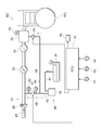
- FIG. 1 is a schematic diagram illustrating a schematic configuration of a vehicle to which an abnormality detection device for an internal combustion engine according to a first embodiment is applied.
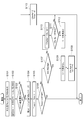
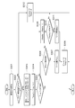
- FIG. 2 is a flowchart of a diagnostic process for leak abnormality of the second purge pipe in the first embodiment.
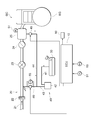
- FIG. 3 is a schematic diagram illustrating a schematic configuration of a vehicle to which the abnormality detection apparatus for an internal combustion engine according to the second embodiment is applied.
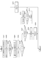
- FIG. 4 is a flowchart of the leakage abnormality diagnosis process for the second purge pipe in the second embodiment.
- FIG. 5 is a schematic diagram showing a schematic configuration of a vehicle to which the abnormality detection device for an internal combustion engine according to the third embodiment is applied.
- FIG. 1 is a schematic diagram illustrating a schematic configuration of a vehicle to which an abnormality detection device for an internal combustion engine according to a first embodiment is applied.
- FIG. 2 is a flowchart of a diagnostic process for leak abnormality of the second purge pipe in the first embodiment.
- FIG. 6 is a flowchart of a leakage abnormality diagnosis process for the second purge pipe in the third embodiment.
- FIG. 7 is a flowchart of a leakage abnormality diagnosis process for the second purge pipe in the fourth embodiment.
- FIG. 8 is a flowchart of the leakage abnormality diagnosis process for the second purge pipe in the fifth embodiment.
- the vehicle GC includes an engine EG, an ECU (Electronic Control Unit) 10, an intake system 20, a fuel tank 30, and an evaporation gas supply system 40.
- ECU Electronic Control Unit
- Engine EG is an internal combustion engine that uses gasoline as fuel.
- the engine EG is arranged in the engine room of the vehicle GC.
- the engine EG has a plurality of cylinders (not shown). Each cylinder generates torque by repeatedly performing each stroke of an intake stroke, a compression stroke, a combustion stroke, and an exhaust stroke.
- the torque is output via a crankshaft (not shown) included in the engine EG and used for traveling of the vehicle GC.
- the intake system 20 is a part that supplies combustion air to each cylinder of the engine EG.
- the intake system 20 includes an intake pipe 21, an air element 22, a compressor 23 (supercharger), and a throttle valve 24.
- the intake pipe 21 is a tubular member having a flow path therein.
- the intake pipe 21 has an intake manifold 25 branched into a plurality at the downstream end thereof.
- the intake pipe 21 takes in air from the outside of the vehicle GC and diverts the air to guide it into the cylinders of the engine EG.
- the air element 22 is a filter-like member that removes foreign matters from the fluid passing therethrough.
- the air element 22 is provided in the intake pipe 21. Thereby, the air element 22 removes foreign matter in the air that is taken in from the outside of the vehicle GC and supplied to the engine EG.
- the compressor 23 is a fluid machine that forms part of the supercharger and compresses the fluid by rotating.
- the compressor 23 is provided in a portion of the intake pipe 21 on the downstream side of the air element 22.
- the compressor 23 is connected to a turbine (not shown) that constitutes a part of the supercharger.
- the turbine is a prime mover that converts energy of fluid into mechanical power, and is provided in an exhaust gas passage (not shown).
- the turbine rotates using the energy of the combustion gas.
- the rotational torque of the turbine is transmitted to the compressor 23 by a shaft (not shown).
- the compressor 23 rotates and sucks and compresses the air on the upstream side of the intake pipe 21 and supplies it to the downstream side.
- the throttle valve 24 is an on-off valve provided in a portion of the intake pipe 21 downstream of the compressor 23.
- the throttle valve 24 has an electric motor and a valve body (not shown). The electric motor is driven based on a control signal received from the ECU 10 described later, and moves the valve body. When the valve body moves, the opening degree of the internal flow path of the throttle valve 24 is adjusted.
- the fuel tank 30 is a tank that stores gasoline as fuel for the engine EG. Usually, the fuel is stored in the fuel tank 30 in a liquid state.
- the fuel tank 30 has a fuel pump (not shown) therein. The fuel pump is driven based on a control signal received from the ECU 10 and pumps fuel to a fuel supply pipe (not shown) connected to the fuel tank 30. The fuel is guided to the engine EG through a fuel supply pipe or the like, and is injected from an injector (not shown) to be atomized and supplied into each cylinder.
- the evaporative gas supply system 40 is a part that supplies evaporative fuel (hereinafter, this evaporative fuel is also referred to as “evaporated gas”), which is gaseous gasoline generated in the fuel tank 30, to the intake pipe 21 or the intake manifold 25.
- evaporation gas supply system 40 includes a communication pipe 41, a canister 42, and a purge pipe 43.
- the communication pipe 41 is a tubular member which is disposed between the fuel tank 30 and the canister 42 and whose end portions are connected to each other.
- the fuel tank 30 and the canister 42 communicate with each other through the communication pipe 41.
- An adsorbent (not shown) is disposed in the internal space of the canister 42.
- a porous member having a large number of pores on the surface such as activated carbon, can be used.
- the canister 42 has an open port (not shown) and is open to the atmosphere at the open port.
- the purge pipe 43 is a tubular member having one end connected to the canister 42.
- the purge pipe 43 is formed to extend from the canister 42 and branch in the middle thereof, and includes a first purge pipe 44 and a second purge pipe 46.
- the end of the first purge pipe 44 is connected to the intake manifold 25.
- a first purge valve 45 that is an on-off valve is provided in the middle of the first purge pipe 44.
- the end of the second purge pipe 46 is connected to the intake pipe 21. Specifically, the end of the second purge pipe 46 is connected to a portion of the intake pipe 21 upstream of the compressor 23 and downstream of the air element 22.
- a second purge valve 47 that is an on-off valve is provided in the middle of the second purge pipe 46.
- the function of the evaporation gas supply system 40 configured as described above will be described.
- the evaporated gas is guided to the canister 42 through the communication pipe 41.
- the evaporative gas guided to the canister 42 is adsorbed by an adsorbent disposed in the internal space.
- the evaporative gas adsorbed by the adsorbent is released by its action when the pressure in the purge pipe 43 becomes negative.
- the first purge valve 45 is opened.
- negative pressure generated when air flows in the intake manifold 25 on the downstream side of the intake pipe acts on the purge pipe 43 and the canister 42 via the first purge pipe 44.
- the inside of the canister 42 becomes negative pressure, air is taken in from the above-described opening and passes through the adsorbent. As a result, the evaporation gas is released from the adsorbent into the air.
- the second purge valve 47 is opened.
- the second purge pipe 46 provided with the second purge valve 47 is connected to the intake pipe 21 on the upstream side of the compressor 23. Therefore, when the compressor 23 is driven, a negative pressure generated in association with the compressor 23 acts on the purge pipe 43 and the canister 42 via the second purge pipe 46.
- the inside of the canister 42 becomes negative pressure, air is taken in from the above-described opening and passes through the adsorbent. As a result, the evaporation gas is released from the adsorbent into the air.
- the intake manifold 25 on the downstream side of the compressor 23 has a positive pressure. Accordingly, the first purge valve 45 is closed in order to prevent the inflow of air from the intake manifold 25 to the first purge pipe 44.
- the evaporative gas released from the adsorbent in the canister 42 in this way flows into the intake pipe 21 and merges with the air flowing through it.
- the mixed fluid of evaporation gas and air flows through the intake pipe 21 as it is and is guided into the cylinders of the engine EG.
- ECU10 is a part which controls operation
- the ECU 10 is electrically connected to various sensors such as an intake pressure sensor 51, a pressure sensor 52, and an atmospheric pressure sensor 53.
- the intake pressure sensor 51 is provided in the intake manifold 25 shown in FIG. 1 and corresponds to the pressure of the fluid flowing in the intake manifold 25 (hereinafter also referred to as “engine intake pipe pressure IA” and “intake pipe side pipe pressure”). This is a sensor that generates and transmits a signal to be transmitted.
- the pressure sensor 52 is provided in the second purge pipe 46 at a position closer to the intake pipe 21 than the second purge valve 47, and the pressure of the evaporation gas flowing in the second purge pipe 46 (hereinafter also referred to as “valve pressure BA”). It is a sensor which produces
- the atmospheric pressure sensor 53 is a sensor that is disposed in a part of the vehicle GC that comes into contact with outside air, and generates and transmits a signal corresponding to the atmospheric pressure PA.
- ECU10 is electrically connected also with each vehicle equipment of engine EG, throttle valve 24, supercharger, and information device 60, and controls operation of engine EG by transmitting a control signal to these. Further, the ECU 10 is electrically connected to the first purge valve 45 and the second purge valve 47, and controls the recirculation operation of the evaporation gas by the evaporation gas supply system 40 by transmitting a control signal thereto and switching the opening and closing appropriately. .
- the notification device 60 is a device for performing various notifications to passengers of the vehicle GC.
- the notification device 60 is configured by a known device such as a display panel or a buzzer.
- the ECU 10 controls the operation of the notification device 60 by transmitting a control signal.
- the ECU 10 is physically configured as a computer system including a CPU, ROM, RAM, and an input / output interface.
- Each function of ECU10 mentioned above is implement
- the second purge pipe 46 is connected between the upstream part of the intake pipe 21 upstream of the compressor 23 (supercharger) and the canister 42 to supply the evaporated gas (evaporated fuel) to the intake pipe 21. Functions as a "purge pipe”. Further, the second purge valve 47 functions as a “switching unit that is provided in the second purge pipe 46 and switches communication / blocking of the second purge pipe 46”.
- the ECU 10, the second purge pipe 46, and the second purge valve 47 function as an “engine EG (internal combustion engine) abnormality detection device” that detects a leak abnormality in the second purge pipe 46.
- an abnormality may occur in the second purge pipe 46, which may cause a problem related to the processing of the evaporation gas. That is, the second purge pipe 46 that should be connected to the intake pipe 21 in the normal state is disconnected from the intake pipe 21 (hereinafter also referred to as “piping disconnection”), or connected to the intake pipe 21 or in the pipe.
- piping disconnection When leakage due to cracks or the like occurs from the inner wall (hereinafter also referred to as “piping leakage”), there is a risk that the evaporation gas flowing in the second purge piping 46 is released to the atmosphere.
- piping leakage When leakage due to cracks or the like occurs from the inner wall (hereinafter also referred to as “piping leakage”), there is a risk that the evaporation gas flowing in the second purge piping 46 is released to the atmosphere.
- piping leakage such a phenomenon is referred to as “leak abnormality”.
- leak occurrence When such a leak abnormality occurs, it is necessary to correct it at a dealer or a maintenance shop, so it is necessary to quickly detect the abnormality and notify the user of the vehicle GC.
- the occurrence of such a leak abnormality is also referred to as “leak occurrence”.
- the ECU 10 executes a process of diagnosing whether there is a leak abnormality in the second purge pipe 46.
- the abnormality determination process shown in FIG. 2 can be performed, for example, at the timing when the supercharger is first driven after the engine EG is started. Note that the initial values of the timer value Timer1 and the counter value Cfault used in the following flowchart are both set to zero.
- step S101 the atmospheric pressure PA as the reference pressure and the valve pressure BA are detected.
- the ECU 10 detects the atmospheric pressure PA based on the signal input from the atmospheric pressure sensor 53 and detects the valve pressure BA based on the signal input from the pressure sensor 52.
- the valve pressure BA is the pressure of the evaporation gas at the position closer to the intake pipe 21 than the second purge valve 47 in the second purge pipe 46.
- step S102 a differential pressure DA between the atmospheric pressure PA detected in step S101 and the valve pressure BA is calculated.
- the ECU 10 calculates the differential pressure DA by subtracting the valve pressure BA from the atmospheric pressure PA as the reference pressure.
- step S103 it is determined whether or not the engine intake pipe pressure IA is greater than a predetermined supercharging threshold value KP1.
- the ECU 10 detects the engine intake pipe pressure IA based on a signal input from the intake pressure sensor 51.
- the engine intake pipe pressure IA is the pressure of intake air flowing through the intake manifold 25 as described above.
- the supercharging threshold value KP1 can be set to a value corresponding to the minimum value of the intake pressure during the supercharging operation in which the intake system 20 drives the supercharger, for example.
- step S103 As a result of the determination in step S103, when the engine intake pipe pressure IA is larger than the supercharging threshold value KP1 (Yes in step S103), the engine EG is in supercharging operation, and the current operating state of the engine EG permits abnormality determination. It is determined that the operating state is acceptable, and the process proceeds to step S104. On the other hand, when the engine intake pipe pressure IA is equal to or lower than the supercharging threshold KP1 (No in step S103), the engine EG is not in supercharging operation, and the current operating state of the engine EG is an operating state in which abnormality determination cannot be permitted. After the determination, the process proceeds to step S113.
- step S104 the second purge valve 47 is controlled to a non-operating state, that is, a closed (closed) state. This process is performed so that the valve pressure BA detected by the pressure sensor 52 is not affected by pressure fluctuations on the fuel tank 30 and canister 42 side.
- step S104 the process proceeds to step S105.
- step S105 the timer value Timer1 is counted up. That is, 1 is added to the timer value Timer1.
- the timer value Timer1 indicates an elapsed time since the second purge valve 47 is deactivated in step S104.
- step S106 it is determined whether or not the timer value Timer1 is smaller than a predetermined stabilization threshold value KTIME1.
- the stabilization threshold value KTIME1 indicates a time required until the pressure (valve pressure BA) in the second purge pipe 46 is stabilized after the second purge valve 47 is inactivated.
- the timer value Timer1 is equal to or greater than the stabilization threshold value KTIME1 (No in step S106)
- the valve pressure BA has stabilized after the required time has elapsed after the second purge valve 47 is deactivated.
- the process proceeds to step S107.
- step S106 if the timer value Timer1 is smaller than the stabilization threshold KTIME1 (Yes in step S106), it is determined that the valve pressure BA is still in an unstable state, and the current diagnosis is stopped to prevent erroneous detection, This control flow ends.
- step S107 it is determined whether or not the differential pressure DA calculated in step S102 is greater than a predetermined determination value A (threshold value).
- a predetermined determination value A threshold value
- the valve pressure BA becomes negative due to the generated pressure loss
- the differential pressure DA calculated in step S102 becomes a positive value.
- the valve pressure BA is a pressure corresponding to atmospheric pressure
- the differential pressure DA calculated in step S102 is A value near 0 is shown.
- the determination value A is set so as to be able to distinguish between such a normal time and a leak abnormality, and for example, a positive value close to the differential pressure at the normal time can be set.
- step S107 if the differential pressure DA is larger than the determination value A (Yes in step S107), it is determined that the second purge pipe 46 is normally connected to the intake pipe 21. At this time, “no leak abnormality” is diagnosed in step S108, the timer value Timer1 and the counter value Cfaulta are reset (both values are returned to 0) in step S109, and this control flow is ended. .
- step S107 if the differential pressure DA is equal to or lower than the determination value A (No in step S107), it is determined that a leak abnormality has occurred in the second purge pipe 46.
- step S110 the counter value Cfault is counted up. That is, 1 is added to the counter value Cfaulta.
- the counter value Cfaulta indicates the duration of the state where the differential pressure DA is equal to or less than the determination value A.
- step S111 it is determined whether or not the counter value Cfault is greater than a predetermined determination threshold value KFAULT.
- the determination threshold value KFAULT indicates the time required until a phenomenon in which the state where the differential pressure DA is equal to or lower than the determination value A is determined to be caused by the occurrence of a leak.
- step S112 “leak abnormality is present” is diagnosed in step S112, the timer value Timer1 and the counter value Cfaulta are reset (both values are returned to 0) in step S109, and this control flow ends. .
- the ECU 10 can warn the driver of the vehicle GC that a leak abnormality has occurred via the notification device 60.
- step S111 if the counter value Cfaulta is equal to or smaller than the predetermined determination threshold value KFAULT (No in step S111) as a result of the determination in step S111, an error has occurred since sufficient time has not yet passed to determine whether the leak abnormality has occurred. In order to prevent detection, the current diagnosis is stopped, and this control flow ends.
- step S113 as a result of the determination in step S103, it is determined that the current operation state of the engine EG is an operation state in which abnormality determination cannot be permitted. Therefore, the current diagnosis is stopped to prevent erroneous detection, and the timer value Timer1 and the counter value Cfaulta are reset (both values are returned to 0), and this control flow ends.
- the abnormality detection apparatus for an internal combustion engine includes a canister 42 that adsorbs an evaporative gas generated by evaporation of fuel in a fuel tank 30, a canister 42, and a compressor 23 in an intake pipe 21 of an engine EG.
- a second purge pipe 46 connected to the upstream upstream portion and supplying the evaporated gas to the intake pipe 21; and a second purge pipe 46 provided in the second purge pipe 46 for switching communication / blocking of the second purge pipe 46.
- a purge valve 47 and an ECU 10 as an abnormality detection unit that detects occurrence of a leak in the second purge pipe 46 are provided.
- the ECU 10 takes in the intake air that is the pressure on the intake pipe 21 side of the second purge valve 47 from the second purge valve 47.
- the occurrence of a leak in the second purge pipe 46 is detected based on a differential pressure DA between the pipe side pipe internal pressure (valve pressure BA) and the atmospheric pressure PA as a predetermined reference pressure.
- the second purge pipe 46 As described above, during the supercharging operation of the engine EG, if the second purge pipe 46 is normally connected to the intake pipe 21, the upstream side of the compressor 23 of the intake pipe 21 becomes negative pressure, so the second purge valve If 47 is closed, the valve pressure BA in the second purge pipe 46 also becomes negative. For this reason, the differential pressure DA between the valve pressure BA and the atmospheric pressure PA becomes relatively large. On the other hand, if any leak abnormality occurs in the second purge pipe 46, the second purge pipe 46 communicates with the atmosphere, and the valve pressure BA remains at atmospheric pressure even when the second purge valve 47 is closed. Since it becomes equivalent to PA, the differential pressure DA between the valve pressure BA and the atmospheric pressure PA becomes relatively small.
- the abnormality detection apparatus for an internal combustion engine according to the first embodiment uses such a characteristic relating to the differential pressure DA between the valve pressure BA and the atmospheric pressure PA, and generates a leak in the second purge pipe 46 based on the differential pressure DA. Can be detected with high accuracy. Therefore, the abnormality detection device for the internal combustion engine according to the first embodiment can accurately detect a leakage abnormality of the second purge pipe 46 that supplies the evaporation gas to the upstream side of the supercharger in the intake pipe 21 of the engine EG.
- the abnormality detection device for an internal combustion engine is provided on the intake pipe 21 side of the second purge valve 47 in the second purge pipe 46, and includes a pressure sensor 52 for detecting the valve pressure BA, and an atmospheric pressure PA. And an atmospheric pressure sensor 53 for detecting.
- the ECU 10 as the abnormality detection unit calculates a differential pressure DA between the valve pressure BA detected by the pressure sensor 52 and the atmospheric pressure PA detected by the atmospheric pressure sensor 53, and the differential pressure DA is equal to or less than the determination value A. Occurrence of leakage in the second purge pipe 46 is sometimes detected.
- the pressure sensor 52 and the atmospheric pressure sensor 53 can be used to directly measure the valve pressure BA and the atmospheric pressure PA used for the calculation of the differential pressure DA. Therefore, a leak occurs in the second purge pipe 46 based on the differential pressure DA. Can be determined with higher accuracy.
- FIGS. 3 and 4 A second embodiment will be described with reference to FIGS. 3 and 4.
- the pressure on the canister 42 side of the second purge valve 47 in the second purge pipe 46 is used instead of the atmospheric pressure PA as the reference pressure of the differential pressure DA used for detecting the leakage abnormality of the second purge pipe 46.
- a canister side pipe internal pressure hereinafter referred to as “valve upstream pressure BA2”.
- the second purge pipe 46 is further provided with a pressure sensor 54 (second pressure sensor) in addition to the pressure sensor 52 (first pressure sensor) for detecting the valve pressure BA.
- the pressure sensor 54 is provided in the second purge pipe 46 at a position closer to the canister 42 than the second purge valve 47, and generates a signal corresponding to the pressure of the evaporation gas flowing through the second purge pipe 46 (valve upstream pressure BA2). It is a sensor that transmits.
- the ECU 10 is electrically connected to the pressure sensor 54, and can detect the valve upstream pressure BA2 based on a signal input from the pressure sensor 54.
- the ECU 10 calculates a differential pressure DA between the valve pressure BA detected by the pressure sensor 52 and the valve upstream pressure BA2 detected by the pressure sensor 54 in the leakage abnormality diagnosis process of the second purge valve 47, and this differential pressure.
- DA is less than or equal to determination value A, the occurrence of a leak in second purge pipe 46 is detected.
- steps S201 and S202 are the same as those in steps S101 and S102 except that “atmospheric pressure PA” in steps S101 and S102 in FIG. 2 is replaced with “valve upstream pressure BA2” detected by the pressure sensor 54.
- Steps S203 and S205 to S213 are the same as steps S103 and S105 to S113 in FIG.
- step S204 in addition to the second purge valve 47 being deactivated in step S104, the first purge valve 45 is also deactivated (closed).
- the portion of the second purge pipe 46 where the pressure sensor 54 is installed is always in communication with the canister 42 upstream of the purge pipe 43.
- the valve upstream pressure BA2 is equivalent to the atmospheric pressure when the second purge valve 47 is closed even during the supercharging operation.
- the intake manifold 25 is at a positive pressure, if the first purge valve 45 is opened, the intake air in the intake manifold 25 is caused by the pressure difference between the valve upstream pressure BA2 and the engine intake pipe pressure IA.
- the valve upstream pressure BA2 (canister side pipe internal pressure) to be applied as the reference pressure for the differential pressure DA is a pressure corresponding to the atmospheric pressure. It can be said that the occurrence of a leak in the second purge pipe 46 is detected by the same method as in the first embodiment in which the atmospheric pressure PA is applied as the DA reference pressure. Therefore, the abnormality detection device for an internal combustion engine according to the second embodiment can achieve the same effects as those of the first embodiment.
- the pressure in the purge pipe may vary depending on the operating state of the engine EG.
- the reference pressure used to calculate the differential pressure DA used for the diagnosis of the leakage abnormality is the pressure in the purge pipe as in the valve pressure BA, and the upstream of the valve fluctuates in the same manner as the valve pressure BA depending on the operating state. Pressure BA2 is used. Therefore, compared to the case where the atmospheric pressure PA is set as the reference pressure, the influence of the operating state of the engine EG is less affected, and a more stable differential pressure DA can be measured. Abnormality detection accuracy can be further improved.
- a third embodiment will be described with reference to FIGS.
- a single differential pressure sensor 55 is used, and the pipe pressure on the intake pipe 21 side of the second purge valve 47 in the second purge pipe 46 and the pipe pressure on the canister 42 side of the second purge valve 47 are calculated.
- the second embodiment is different from the second embodiment in that a differential pressure DPA is detected.
- the differential pressure sensor 55 is provided across the portion of the second purge pipe 46 between the portion of the intake pipe 21 side and the portion of the canister 42 side of the second purge valve 47, This is a sensor that generates and transmits a signal corresponding to the differential pressure DPA.
- the ECU 10 is electrically connected to the differential pressure sensor 55 and can detect the differential pressure DPA based on a signal input from the differential pressure sensor 55.
- the ECU 10 detects the occurrence of a leak in the second purge pipe 46 when the differential pressure DPA detected by the differential pressure sensor 55 is equal to or less than the determination value A.
- step S301 is a process instead of the processes of steps S201 and S202 of FIG.
- step S301 a differential pressure DPA between the pipe pressure on the intake pipe 21 side of the second purge valve 47 and the pipe pressure on the canister 42 side of the second purge valve 47 in the second purge pipe 46 is detected.
- the ECU 10 detects the differential pressure DPA based on a signal input from the differential pressure sensor 55.
- steps S302 to S312 are the same as the processes in steps S203 to S213 in FIG.
- the abnormality detection apparatus for an internal combustion engine according to the third embodiment includes the internal pressure on the intake pipe 21 side from the second purge valve 47 in the second purge pipe 46 and the internal pressure on the canister 42 side from the second purge valve 47.
- the second embodiment is common to the second embodiment in that the occurrence of leakage in the second purge pipe 46 is detected based on the differential pressure DPA between the first and second purge pipes 46. Therefore, the abnormality detection apparatus for an internal combustion engine according to the third embodiment can achieve the same effects as those of the first and second embodiments.
- the single differential pressure sensor 55 is used for detecting the differential pressure DPA, the number of sensors can be reduced, and the space of the entire apparatus can be saved.
- the first to third embodiments are configured to detect a leakage abnormality of the second purge pipe 46, and the contents of the leakage abnormality are “piping disconnection” and “piping leakage”. It is different from the first to third embodiments in that it can be detected by classifying it.
- steps S401 to S409 are the same as steps S101 to S109 of FIG.
- the apparatus configuration of the fourth embodiment is the same as that of the first embodiment shown in FIG.
- step S410 it is determined whether or not the differential pressure DA calculated in step S402 is equal to or greater than a predetermined determination value B (second threshold) and equal to or less than the determination value A (first threshold).
- the determination value A is the same as in the first to third embodiments.
- the second purge pipe 46 is normally connected upstream of the intake pipe 21 and the supercharger (compressor 23). In this case (hereinafter, referred to as “normal”), a positive value close to the differential pressure DA can be set.
- the determination value B is set so that the differential pressure when the leakage abnormality of the second purge pipe 46 is out of the pipe and the differential pressure when the pipe leaks can be distinguished.
- the determination value B is a positive value smaller than the determination value A.
- step S410 if the differential pressure DA is greater than or equal to the determination value B and less than or equal to the determination value A (Yes in step S410), the differential pressure DA when compared with normal (DA> A) is determined. Since the degree of reduction is relatively small, it is determined that “piping leakage” with a relatively small amount of leakage has occurred.
- step S411 the counter value Cfaultb is counted up. That is, 1 is added to the counter value Cfaultb. This counter value Cfaultb indicates the duration of the state in which the differential pressure DA is not less than the determination value B and not more than the determination value A.
- step S412 it is determined whether or not the counter value Cfaultb is greater than a predetermined determination threshold value KFAULT.
- the determination threshold value KFAULT indicates a time required until a phenomenon in which the state where the differential pressure DA is equal to or greater than the determination value B and equal to or less than the determination value A is determined to be caused by the occurrence of pipe leakage.
- the counter value Cfaultb is larger than the predetermined determination threshold value KFAULT (Yes in step S412), it is determined that a leak abnormality of the pipe leak has occurred in the second purge pipe 46.
- step S413 “piping leakage” is diagnosed in step S413, and the counter values Cfaulta, Cfaultb and timer value Timer1 are reset (both values are returned to 0) in step S414, and this control flow is performed. finish.
- the ECU 10 can issue a warning to the driver of the vehicle GC that a leak abnormality of the pipe leak has occurred via the notification device 60.
- step S412 If the result of determination in step S412 is that the counter value Cfaultb is less than or equal to the predetermined determination threshold value KFAULT (No in step S412), a sufficient time has not yet passed to determine the occurrence of pipe leakage, and thus a false detection In order to prevent this, the current diagnosis is stopped and this control flow is terminated.
- step S410 if the differential pressure DA is smaller than the determination value B (No in step S410), the degree of reduction of the differential pressure DA relative to the normal time (DA> A) is relatively high. Since it is large, it is judged that “piping disconnection” having a relatively large amount of leakage has occurred.
- step S415 the counter value Cfaulta is counted up. That is, 1 is added to the counter value Cfaulta.
- the counter value Cfaulta indicates the duration of the state in which the differential pressure DA is smaller than the determination value B.
- step S416 it is determined whether or not the counter value Cfault is greater than a predetermined determination threshold value KFAULT.
- the determination threshold value KFAULT indicates the time required until the phenomenon in which the state where the differential pressure DA is smaller than the determination value B is determined to be caused by the occurrence of pipe disconnection.
- step S417 it is diagnosed that “the pipe is disconnected”, and in step S418, the counter values Cfaulta, Cfaultb and the timer value Timer1 are reset (both values are returned to 0), and this control flow is performed. finish.
- the ECU 10 can give a warning to the driver of the vehicle GC that a leakage abnormality of the pipe has occurred via the notification device 60.
- step S416 determines whether the counter value Cfault is less than or equal to the predetermined determination threshold KFAULT (No in step S416). If the result of determination in step S416 is that the counter value Cfault is less than or equal to the predetermined determination threshold KFAULT (No in step S416), sufficient time has not yet passed to determine the occurrence of pipe disconnection. In order to prevent erroneous detection, the current diagnosis is stopped and this control flow is terminated.
- step S419 as a result of the determination in step S403, it is determined that the current operation state of the engine EG is an operation state in which the abnormality determination cannot be permitted. Therefore, the current diagnosis is stopped to prevent erroneous detection, and the counter value Cfaulta, Cfaultb, and timer value Timer1 are reset (both values are returned to 0), and this control flow ends.
- the abnormality detection device for an internal combustion engine of the internal combustion engine according to the fourth embodiment has the same configuration as that of the first embodiment, and the inside of the second purge pipe 46 is closer to the intake pipe 21 than the second purge valve 47.
- This is common to the first embodiment in that the occurrence of a leak in the second purge pipe 46 is detected based on the differential pressure DA between the valve pressure BA, which is a pressure, and the atmospheric pressure PA.
- the leak abnormality detection method of the fourth embodiment described with reference to FIG. 7 can also be applied to the configuration that detects the occurrence of leak in the second purge pipe 46 based on the pressure. Therefore, the abnormality detection apparatus for an internal combustion engine according to the fourth embodiment can achieve the same effects as those of the first to third embodiments.
- the ECU 10 as the abnormality detection unit indicates that the pipe leakage of the second purge pipe 46 has occurred when the differential pressure DP is equal to or lower than the determination value A and equal to or higher than the determination value B.
- the differential pressure DP is smaller than the determination value B, it is detected that the second purge pipe 46 is disconnected.
- a configuration in which two types of leakage abnormality, “displacement of piping” and “piping leakage”, can be identified by comparing the differential pressure DP with the determination values A and B. It can also be set as the structure which identifies 3 or more types of leak abnormality by increasing to 3 or more types.
- a fifth embodiment will be described with reference to FIG.
- the fifth embodiment is different from the first embodiment in a method for determining whether or not a supercharging operation, which is a condition under which the process can be performed, in the leak abnormality determination process.
- steps S104 to S113 are the same as those in FIG. Only steps S101A, S102A, and S103A that are different from FIG. 2 will be described below.
- step S101A an atmospheric pressure PA as a reference pressure, a valve pressure BA, and an engine intake pipe pressure IA are detected.
- the process of step S101A proceeds to step S102A.
- step S102A a differential pressure DA between the atmospheric pressure PA detected in step S101A and the valve pressure BA is calculated, and a differential pressure DIPA between the engine intake pipe pressure IA detected in step S101A and the atmospheric pressure PA. Is calculated.
- the ECU 10 calculates the differential pressure DA by subtracting the valve pressure BA from the atmospheric pressure PA as the reference pressure, and calculates the differential pressure DIPA by subtracting the atmospheric pressure PA from the engine intake pipe pressure IA.
- step S103A it is determined whether or not the differential pressure DIPA calculated in step S102A is greater than a predetermined supercharging threshold value KP1. As a result of the determination in step S103A, when the differential pressure DIPA is larger than the supercharging threshold KP1 (Yes in step S103A), even if the engine EG is in supercharging operation and the current operating state of the engine EG permits abnormality determination It is determined that the driving state is good, and the process proceeds to step S104.
- step S103A when the differential pressure DIPA is equal to or lower than the supercharging threshold KP1 (No in step S103A), it is determined that the engine EG is not in supercharging operation and the current operating state of the engine EG is an operating state in which abnormality determination cannot be permitted. Then, the process proceeds to step S113.
- the supercharging region in a place where the atmospheric pressure PA is low can be determined. It is possible to diagnose the occurrence of leak abnormality without being affected by PA.
- the fifth embodiment has the same configuration as that of the first embodiment except for the supercharging region determination method, the same effect as that of the first embodiment can be obtained. Also, the supercharging region determination method of the fifth embodiment described with reference to FIG. 8 can be applied to the second to fourth embodiments.
- the valve upstream pressure BA2 is used as the reference pressure instead of the atmospheric pressure PA
- the “atmospheric pressure PA” in the above steps S101A to S103A is changed to the “valve upstream pressure BA2”. Replace it.
- the time of performing the abnormality detection processing of the second purge pipe 46 is exemplified as the supercharging operation of the engine EG.
- the portion of the intake pipe 21 upstream of the compressor 23 has a negative pressure. It is sufficient that the engine EG is operating under the operating conditions, and it can be set to be performed under operating conditions other than during supercharging operation.
- the configuration in which the atmospheric pressure PA or the valve upstream pressure BA2 is applied as the reference pressure for calculating the differential pressure DP is exemplified.
- the reference pressure is determined depending on whether there is a leakage abnormality in the second purge pipe 46.
- a pressure value other than the atmospheric pressure PA or the valve upstream pressure BA2 may be applied as long as it has a significant difference in DP.
- the configuration in which the second purge pipe 46 is connected / blocked by controlling the opening / closing of the second purge valve 47 is illustrated, but the configuration may be switched by an element other than the valve.
Landscapes
- Engineering & Computer Science (AREA)
- Chemical & Material Sciences (AREA)
- Combustion & Propulsion (AREA)
- Mechanical Engineering (AREA)
- General Engineering & Computer Science (AREA)
- Supplying Secondary Fuel Or The Like To Fuel, Air Or Fuel-Air Mixtures (AREA)
Abstract
内燃機関の異常検出装置は、第2パージ配管(46)のリーク発生を検出する異常検出部としてのECU(10)とを備える。ECU(10)は、過給機による過給時、かつ、第2パージバルブ(47)により第2パージ配管(46)が遮断状態のとき、第2パージ配管(46)のうち第2パージバルブ(47)より吸気管(21)側の圧力(バルブ圧力BA)と、大気圧(PA)との差圧(DA)に基づき、第2パージ配管(46)のリーク発生を検出する。
Description
本出願は、2015年11月16日に出願された日本国特許出願2015-223612号に基づくものであって、その優先権の利益を主張するものであり、その特許出願の全ての内容が、参照により本明細書に組み込まれる。
本開示は、内燃機関の吸気管のうち過給機よりも上流側に蒸発燃料を供給するパージ配管のリーク発生を検出するための内燃機関の異常検出装置に関する。
未燃焼の蒸発燃料(エバポガス(Evaporation Gas)ともいう)を内燃機関(エンジン)の吸気管に供給することによって、エンジンの燃費向上を図る技術が知られている。例えば、特許文献1には、燃料タンク内で燃料が蒸発して発生した蒸発燃料をキャニスタで一旦捕集すると共に、その蒸発燃料を吸気管に供給する装置が記載されている。蒸発燃料は、キャニスタ及び吸気管と接続されるパージ配管によってキャニスタから吸気管に供給される。また、キャニスタからの蒸発燃料のパージは、燃焼用の空気が吸気管を流れることで発生する負圧を用いて行われる。特許文献1に記載の装置は、キャニスタを含む蒸発燃料の供給系統の診断を行う。詳細には、当該装置は、燃料タンク内の圧力を検出すると共に、その圧力に基づいて供給系統の異常の有無を診断する。
ところで、近年の燃費向上策として、エンジンの排気量を小型化する手法、所謂ダウンサイジング化が知られている。このようなダウンサイジング化されたエンジンが高排気量と同等の出力性能を得るための手段として過給機付きエンジンが知られている。過給機付きエンジンは、ダウンサイジングに伴って低下する出力を過給機によって補うことができる。過給機は、エンジンから排出された燃焼ガスの運動エネルギーを利用してタービンを駆動させ、このタービンに伴って駆動するコンプレッサによって燃焼用の空気を加圧する。コンプレッサによって加圧された燃焼用の空気は、吸気管を介して燃焼室内に供給される。
過給機付きエンジンでは、エンジンの負圧領域での運転期間が減少し、また、過給領域の運転時には、吸気管のうちコンプレッサよりも下流側の部位は、コンプレッサの駆動により正圧となる。したがって、前述した蒸発燃料を供給するパージ配管は、吸気管において発生する負圧を作用させるために、吸気管のうちコンプレッサよりも上流側の部位に接続される必要がある。この構成により、過給運転時でもキャニスタからの蒸発燃料を吸気管へパージでき、積極的に蒸発燃料をエンジンに還流させることができる。
発明者の詳細な検討の結果、このようなパージ配管の構成を備える過給機付きエンジンにおいて、パージ配管と吸気管との接続不良等の異常が生じると、パージ配管から蒸発燃料が大気に放出されるおそれがあるという課題が見出された。特許文献1にはこのようなパージ配管に係る構成の記載がなく、したがって、このパージ配管の異常を検出する具体的な手法も開示されていない。
本開示は、内燃機関の吸気管のうち過給機よりも上流側に蒸発燃料を供給するパージ配管の異常を精度良く検出できる内燃機関の異常検出装置を提供することを目的とする。
本開示の一態様による内燃機関の異常検出装置は、燃料タンク内の燃料が蒸発して生じた蒸発燃料を吸着するキャニスタと、前記キャニスタと、内燃機関の吸気管のうち過給機より上流側の上流側部分との間に接続され、前記蒸発燃料を前記吸気管に供給するパージ配管と、前記パージ配管に設けられ、前記パージ配管の連通/遮断を切り替える切替部と、前記上流側部分が負圧となる特定運転条件で前記内燃機関が運転しており、かつ、前記切替部により前記パージ配管が遮断状態のとき、前記パージ配管のうち前記切替部より前記吸気管側の圧力である吸気管側管内圧力(BA)と、所定の基準圧力との差圧に基づき、前記パージ配管のリーク発生を検出する異常検出部と、を備える。
吸気管のうち過給機より上流側部分が負圧となる特定運転条件で内燃機関が運転しているときには、パージ配管が吸気管と正常に接続されていればパージ配管内の管内圧力も負圧となる。このため、管内圧力と基準圧力との差圧は相対的に大きくなる。一方、パージ配管に何らかのリーク異常が発生している場合には、パージ配管が大気と連通してしまい、管内圧力は負圧ではなく大気圧と同等となってしまうため、管内圧力と基準圧力との差圧は相対的に小さくなる。本開示の一態様に係る内燃機関の異常検出装置は、このようなパージ配管の管内圧力と基準圧力との差圧の特性を利用して、この差圧に基づきパージ配管のリーク発生を高精度に検出できる。
本開示によれば、内燃機関の吸気管のうち過給機よりも上流側に蒸発燃料を供給するパージ配管の異常を精度良く検出できる内燃機関の異常検出装置を提供することができる。
以下、添付図面を参照しながら本実施形態について説明する。説明の理解を容易にするため、各図面において同一の構成要素に対しては可能な限り同一の符号を付して、重複する説明は省略する。
[第1実施形態]
図1及び図2を参照して第1実施形態を説明する。まず図1を参照して、第1実施形態に係る内燃機関の異常検出装置が適用される車両GCの構成について説明する。図1に示されるように、車両GCは、エンジンEGと、ECU(Electronic Control Unit)10と、吸気系統20と、燃料タンク30と、エバポガス供給系統40と、を備えている。
図1及び図2を参照して第1実施形態を説明する。まず図1を参照して、第1実施形態に係る内燃機関の異常検出装置が適用される車両GCの構成について説明する。図1に示されるように、車両GCは、エンジンEGと、ECU(Electronic Control Unit)10と、吸気系統20と、燃料タンク30と、エバポガス供給系統40と、を備えている。
エンジンEGは、ガソリンを燃料とする内燃機関である。エンジンEGは、車両GCのエンジンルームに配置されている。エンジンEGは、不図示の気筒を複数有している。各気筒は、吸気行程、圧縮行程、燃焼行程、及び排気行程の各行程を繰り返し行うことによってトルクを発生させる。当該トルクは、エンジンEGが有する不図示のクランク軸を介して出力され、車両GCの走行に用いられる。
吸気系統20は、エンジンEGの各気筒に燃焼用の空気を供給する部分である。吸気系統20は、吸気管21と、エアエレメント22と、コンプレッサ23(過給機)と、スロットルバルブ24と、を有している。
吸気管21は、その内部に流路を有する管状部材である。吸気管21は、その下流側端部に、複数に分岐するインテークマニホールド25を有している。吸気管21は、車両GCの外部から空気を取り込むともに、その空気を分流させてエンジンEGの各気筒の内部に導く。
エアエレメント22は、通過する流体から異物を除去するフィルタ状の部材である。エアエレメント22は、吸気管21に設けられている。これにより、エアエレメント22は、車両GCの外部から取り込まれてエンジンEGに供給される空気中の異物を除去する。
コンプレッサ23は、過給機の一部を構成し、回転することによって流体を圧縮する流体機械である。コンプレッサ23は、吸気管21のうちエアエレメント22よりも下流側の部位に設けられている。コンプレッサ23は、過給機の一部を構成する不図示のタービンと連結されている。当該タービンは、流体が有するエネルギーを機械的動力に変換する原動機であり、不図示の排出ガス流路に設けられている。エンジンEGの燃焼行程において発生した燃焼ガスが排出ガス流路を流れると、タービンはその燃焼ガスのエネルギーを利用して回転する。タービンの回転トルクは不図示のシャフトによってコンプレッサ23に伝達される。これにより、コンプレッサ23が回転し、吸気管21の上流側の空気を吸引して圧縮するとともに、下流側に供給する。
スロットルバルブ24は、吸気管21のうちコンプレッサ23より下流側の部位に設けられた開閉弁である。スロットルバルブ24は、いずれも不図示の電動モータ及び弁体を有している。当該電動モータは、後述するECU10から受信する制御信号に基づいて駆動し、弁体を移動させる。当該弁体が移動すると、スロットルバルブ24の内部流路の開度が調整される。
燃料タンク30は、エンジンEGの燃料であるガソリンを貯留するタンクである。通常、燃料は液体状で燃料タンク30内に貯留される。燃料タンク30は、不図示の燃料ポンプをその内部に有している。燃料ポンプは、ECU10から受信する制御信号に基づいて駆動し、燃料タンク30に接続された不図示の燃料供給管に燃料を圧送する。当該燃料は、燃料供給管等によってエンジンEGに導かれ、不図示のインジェクタから噴射されて霧状になって各気筒の内部に供給される。
エバポガス供給系統40は、燃料タンク30で発生した気体状のガソリンである蒸発燃料(以下、この蒸発燃料を「エバポガス」とも称する)を、吸気管21またはインテークマニホールド25に供給する部分である。エバポガス供給系統40は、連通管41と、キャニスタ42と、パージ配管43と、を有している。
連通管41は、燃料タンク30とキャニスタ42との間に配置され、端部がそれぞれに接続された管状部材である。燃料タンク30とキャニスタ42とは、この連通管41を介して互いに連通している。
キャニスタ42の内部空間には、不図示の吸着体が配置されている。この吸着体としては、例えば活性炭等、表面に多数の細孔を有する多孔質部材を用いることができる。キャニスタ42は、不図示の開放口が形成されており、当該開放口において大気開放されている。
パージ配管43は、その一端部がキャニスタ42に接続された管状部材である。パージ配管43は、キャニスタ42から延びてその途中で分岐するように形成されており、第1パージ配管44と、第2パージ配管46と、を有している。第1パージ配管44は、その端部がインテークマニホールド25に接続されている。第1パージ配管44の途中には、開閉弁である第1パージバルブ45が設けられている。第2パージ配管46は、その端部が吸気管21に接続されている。詳細には、第2パージ配管46の端部は、吸気管21のうちコンプレッサ23よりも上流側で、且つエアエレメント22よりも下流側の部位に接続されている。第2パージ配管46の途中には、開閉弁である第2パージバルブ47が設けられている。
続いて、以上のように構成されたエバポガス供給系統40の機能について説明する。燃料タンク30内で燃料が揮発してエバポガスが発生すると、当該エバポガスは、連通管41によってキャニスタ42に導かれる。
キャニスタ42に導かれたエバポガスは、その内部空間に配置された吸着体によって吸着される。当該吸着体によって吸着されたエバポガスは、パージ配管43内が負圧になると、その作用によって放出される。
例えば、コンプレッサ23が駆動することなくエンジンEGが運転している場合は、第1パージバルブ45が開弁する。これにより、吸気管下流側のインテークマニホールド25内を空気が流れることで発生する負圧が、第1パージ配管44を介してパージ配管43、及びキャニスタ42に作用する。キャニスタ42内が負圧になると、前述した開放口から空気が取り込まれて吸着体を通過する。これにより、吸着体から空気にエバポガスが放出される。
一方、コンプレッサ23が駆動している状態でエンジンEGが運転している場合は、第2パージバルブ47が開弁する。前述したように、第2パージバルブ47が設けられる第2パージ配管46は、コンプレッサ23よりも上流側で吸気管21と接続している。したがって、コンプレッサ23が駆動すると、それに伴って発生する負圧が第2パージ配管46を介してパージ配管43、及びキャニスタ42に作用する。キャニスタ42内が負圧になると、前述した開放口から空気が取り込まれて吸着体を通過する。これにより、吸着体から空気にエバポガスが放出される。
尚、コンプレッサ23が駆動している状態では、コンプレッサ23の下流側であるインテークマニホールド25内は正圧となる。したがって、インテークマニホールド25から第1パージ配管44への空気の流入を防止するために、第1パージバルブ45は閉弁する。
このようにしてキャニスタ42内の吸着体から放出されたエバポガスは、吸気管21内に流入し、その内部を流れる空気と合流する。エバポガスと空気との混合流体は、そのまま吸気管21内を流れてエンジンEGの各気筒の内部に導かれる。これにより、エバポガスを大気に放出することなくエンジンEGの運転に利用し、エンジンEGの燃費を向上させることが可能となる。
ECU10は、車両GC内のセンサ類から取得される各種情報に基づいて、エンジンEG、吸気系統20、エバポガス供給系統40、などの車両GC内の各車載機器の動作を制御する部分である。ECU10は、吸気圧センサ51、圧力センサ52、大気圧センサ53の各種センサと電気的に接続されている。
吸気圧センサ51は、図1に示したインテークマニホールド25に設けられ、インテークマニホールド25内を流れる流体の圧力(以下では「エンジン吸気管圧力IA」「吸気管側管内圧力」とも表記する)に対応する信号を生成して送信するセンサである。
圧力センサ52は、第2パージ配管46において、第2パージバルブ47より吸気管21側の位置に設けられ、第2パージ配管46内を流れるエバポガスの圧力(以下では「バルブ圧力BA」とも表記する)に対応する信号を生成して送信するセンサである。
大気圧センサ53は、車両GCのうち外気に触れる部位に配置され、大気圧PAに対応する信号を生成して送信するセンサである。
ECU10は、エンジンEG、スロットルバルブ24、過給機、及び報知装置60の各車載機器とも電気的に接続されており、これらに制御信号を送信することによって、エンジンEGの動作を制御する。また、ECU10は、第1パージバルブ45及び第2パージバルブ47と電気的に接続されており、これらに制御信号を送信して開閉を適宜切り替えることによって、エバポガス供給系統40によるエバポガスの還流動作を制御する。
報知装置60は、車両GCの乗員に対して種々の報知を行うための装置である。報知装置60は、例えば表示パネルやブザー等、公知の機器によって構成される。ECU10は、制御信号を送信することによって報知装置60の動作を制御する。
ECU10は、物理的には、CPU、ROM、RAM、入出力インタフェースを備えたコンピュータシステムとして構成される。上述したECU10の各機能は、ROMに保持されるアプリケーションプログラムをRAMにロードしてCPUで実行することによって、RAMやROMにおけるデータの読み出し及び書き込みを行うことで実現される。
なお、第2パージ配管46が、「吸気管21のうちコンプレッサ23(過給機)より上流側の上流側部分とキャニスタ42との間に接続され、エバポガス(蒸発燃料)を吸気管21に供給するパージ配管」として機能する。また、第2パージバルブ47が、「第2パージ配管46に設けられ、第2パージ配管46の連通/遮断を切り替える切替部」として機能する。ECU10と、第2パージ配管46と、第2パージバルブ47とが、第2パージ配管46のリーク異常を検出する「エンジンEG(内燃機関)の異常検出装置」として機能する。
ところで、上記のように構成された車両GCでは、第2パージ配管46に異常が生じることによって、エバポガスの処理に関する不具合が生じるおそれがある。つまり、正常時では吸気管21と接続されているはずの第2パージ配管46が、吸気管21から外れたり(以下「配管外れ」ともいう)、または、吸気管21との接続部分もしくは管内の内壁から亀裂などに起因する漏れが発生する(以下「配管漏れ」ともいう)ことで、第2パージ配管46内を流れるエバポガスが大気に放出されてしまうおそれがある。以降では、このような現象を「リーク異常」と呼ぶ。このようなリーク異常が発生した場合には、ディーラーや整備工場にて修正を行う必要があるため、速やかに異常を検出し車両GCのユーザに通達する必要がある。なお、このようなリーク異常の発生を「リーク発生」とも表記する。
そこで本実施形態では、ECU10は、第2パージ配管46のリーク異常の有無を診断する処理を実行する。図2のフローチャートを参照しながら、ECU10が実行する、第2パージ配管46のリーク異常の異常判定処理について説明する。図2に示される異常判定処理は、例えばエンジンEGの始動後に過給機を最初に駆動させたタイミングで実施することができる。なお、下記のフローチャートで用いるタイマー値Timer1、及び、カウンタ値Cfaultaの初期値は共に0に設定される。
ステップS101では、基準圧力としての大気圧PAと、バルブ圧力BAとが検出される。ECU10は、大気圧センサ53から入力される信号に基づき大気圧PAを検出し、圧力センサ52から入力される信号に基づきバルブ圧力BAを検出する。バルブ圧力BAは、上述のように、第2パージ配管46内の第2パージバルブ47より吸気管21側の位置におけるエバポガスの圧力である。ステップS101の処理が完了するとステップS102に進む。
ステップS102では、ステップS101にて検出された大気圧PAとバルブ圧力BAとの差圧DAが算出される。ECU10は、例えば、基準圧力としての大気圧PAからバルブ圧力BAを減算することにより差圧DAを算出する。ステップS102の処理が完了するとステップS103に進む。
ステップS103では、エンジン吸気管圧力IAが所定の過給閾値KP1より大きいか否かが判定される。ECU10は、吸気圧センサ51から入力される信号に基づきエンジン吸気管圧力IAを検出する。エンジン吸気管圧力IAとは、上述のとおり、インテークマニホールド25内を流れる吸入空気の圧力である。過給閾値KP1は、例えば、吸気系統20が過給機を駆動させている過給運転のときの吸気圧の最小値に相当する値を設定することができる。ステップS103の判定の結果、エンジン吸気管圧力IAが過給閾値KP1より大きいとき(ステップS103のYes)、エンジンEGが過給運転中であり、エンジンEGの現在の運転状態が異常判定を許可しても良い運転状態であると判断されて、ステップS104に進む。一方、エンジン吸気管圧力IAが過給閾値KP1以下のとき(ステップS103のNo)、エンジンEGが過給運転中ではなく、エンジンEGの現在の運転状態が異常判定を許可できない運転状態であると判断されて、ステップS113に進む。
ステップS104では、第2パージバルブ47が非作動状態、つまり閉弁(クローズ)状態に制御される。この処理は、圧力センサ52により検出されるバルブ圧力BAが、燃料タンク30及びキャニスタ42側の圧力変動の影響を受けないようにするために行われる。ステップS104の処理が完了するとステップS105に進む。
ステップS105では、タイマー値Timer1がカウントアップされる。すなわちタイマー値Timer1に1が加算される。このタイマー値Timer1は、ステップS104にて第2パージバルブ47が非作動状態にされてからの経過時間を示す。ステップS105の処理が完了するとステップS106に進む。
ステップS106では、タイマー値Timer1が所定の安定化閾値KTIME1より小さいか否かが判定される。安定化閾値KTIME1は、第2パージバルブ47が非作動状態にされた後に第2パージ配管46内の圧力(バルブ圧力BA)が安定するまでの所要時間を示す。ステップS106の判定の結果、タイマー値Timer1が安定化閾値KTIME1以上の場合(ステップS106のNo)、第2パージバルブ47が非作動状態にされた後に所要時間が経過してバルブ圧力BAが安定化したものと判断されてステップS107に進む。一方、タイマー値Timer1が安定化閾値KTIME1より小さい場合(ステップS106のYes)、まだバルブ圧力BAが不安定な状態であるものと判断され、誤検出を防止するために今回の診断が中止され、本制御フローを終了する。
ステップS107では、ステップS102にて算出された差圧DAが所定の判定値A(閾値)より大きいか否かが判定される。ここで、第2パージ配管46が吸気管21と過給機(コンプレッサ23)の上流にて正常に繋がっている場合には、エンジンEGの過給運転によりエアエレメント22とコンプレッサ23との間で発生する圧力損失によりバルブ圧力BAは負圧となるため、ステップS102にて算出した差圧DAは正の値となる。一方、第2パージ配管46に配管外れや配管漏れなどの何らかのリーク異常が発生している場合には、バルブ圧力BAは大気圧相当の圧力となるため、ステップS102にて算出した差圧DAは0近傍の値を示す。判定値Aは、このような正常時とリーク異常時とを区別できるように設定され、例えば、正常時の差圧に近い正の値を設定することができる。
ステップS107の判定の結果、差圧DAが判定値Aより大きい場合(ステップS107のYes)、第2パージ配管46は吸気管21と正常に接続されているものと判断される。このとき、ステップS108にて「リーク異常なし」と診断され、ステップS109にてタイマー値Timer1、及び、カウンタ値Cfaultaがリセットされて(共に値を0に戻されて)、本制御フローを終了する。
一方、ステップS107の判定の結果、差圧DAが判定値A以下の場合(ステップS107のNo)、第2パージ配管46にリーク異常が発生しているものと判断される。まず、ステップS110にてカウンタ値Cfaultaがカウントアップされる。すなわちカウンタ値Cfaultaに1が加算される。このカウンタ値Cfaultaは、差圧DAが判定値A以下となっている状態の継続時間を示す。ステップS110の処理が完了するとステップS111に進む。
ステップS111では、カウンタ値Cfaultaが所定の判定閾値KFAULTより大きいか否かが判定される。判定閾値KFAULTは、差圧DAが判定値A以下となる状態が継続されている現象が、リーク発生に起因するものと確定されるまでの所要時間を示す。ステップS111の判定の結果、カウンタ値Cfaultaが所定の判定閾値KFAULTより大きい場合(ステップS111のYes)、第2パージ配管46にリーク異常が発生しているものと確定される。このとき、ステップS112にて「リーク異常あり」と診断され、ステップS109にてタイマー値Timer1、及び、カウンタ値Cfaultaがリセットされて(共に値を0に戻されて)、本制御フローを終了する。また、ECU10は、ステップS112の処理と併せて、報知装置60を介して車両GCのドライバに対してリーク異常発生の旨の警告を行うことができる。
一方、ステップS111の判定の結果、カウンタ値Cfaultaが所定の判定閾値KFAULT以下の場合(ステップS111のNo)には、まだリーク異常発生を確定させるために充分な時間が経過していないため、誤検出を防止するために今回の診断が中止され、本制御フローを終了する。
ステップS113では、ステップS103の判定の結果、エンジンEGの現在の運転状態が異常判定を許可できない運転状態であると判断されたので、誤検出を防止するために今回の診断が中止され、タイマー値Timer1、及び、カウンタ値Cfaultaがリセットされて(共に値を0に戻されて)、本制御フローを終了する。
次に、第1実施形態に係る内燃機関の異常検出装置の効果について説明する。
第1実施形態に係る内燃機関の異常検出装置は、燃料タンク30内の燃料が蒸発して生じたエバポガスを吸着するキャニスタ42と、このキャニスタ42と、エンジンEGの吸気管21のうちコンプレッサ23より上流側の上流側部分との間に接続され、エバポガスを吸気管21に供給する第2パージ配管46と、第2パージ配管46に設けられ、第2パージ配管46の連通/遮断を切り替える第2パージバルブ47と、第2パージ配管46のリーク発生を検出する異常検出部としてのECU10とを備える。ECU10は、過給機による過給時、かつ、第2パージバルブ47により第2パージ配管46が遮断状態のとき、第2パージ配管46のうち第2パージバルブ47より吸気管21側の圧力である吸気管側管内圧力(バルブ圧力BA)と、所定の基準圧力としての大気圧PAとの差圧DAに基づき、第2パージ配管46のリーク発生を検出する。
上述のとおり、エンジンEGの過給運転時には、第2パージ配管46が吸気管21と正常に接続されている場合には、吸気管21のコンプレッサ23より上流側が負圧となるため、第2パージバルブ47が閉弁されていれば第2パージ配管46内のバルブ圧力BAも負圧となる。このため、バルブ圧力BAと大気圧PAとの差圧DAは相対的に大きくなる。一方、第2パージ配管46に何らかのリーク異常が発生している場合には、第2パージ配管46が大気と連通してしまい、第2パージバルブ47が閉弁されていてもバルブ圧力BAは大気圧PAと同等となってしまうため、バルブ圧力BAと大気圧PAとの差圧DAは相対的に小さくなる。第1実施形態に係る内燃機関の異常検出装置は、このようなバルブ圧力BAと大気圧PAとの差圧DAに関する特性を利用して、この差圧DAに基づき第2パージ配管46のリーク発生を高精度に検出できる。したがって、第1実施形態に係る内燃機関の異常検出装置は、エンジンEGの吸気管21のうち過給機よりも上流側にエバポガスを供給する第2パージ配管46のリーク異常を精度良く検出できる。
また、第1実施形態に係る内燃機関の異常検出装置は、第2パージ配管46のうち第2パージバルブ47より吸気管21側に設けられ、バルブ圧力BAを検出する圧力センサ52と、大気圧PAを検出する大気圧センサ53と、を備える。異常検出部としてのECU10は、圧力センサ52により検出されたバルブ圧力BAと、大気圧センサ53により検出された大気圧PAとの差圧DAを算出し、この差圧DAが判定値A以下のときに第2パージ配管46のリーク発生を検出する。
この構成により、圧力センサ52及び大気圧センサ53を利用して、差圧DAの算出に用いるバルブ圧力BA及び大気圧PAを直接計測できるので、差圧DAに基づく第2パージ配管46のリーク発生をより一層精度良く判定することができる。
[第2実施形態]
図3及び図4を参照して第2実施形態について説明する。第2実施形態は、第2パージ配管46のリーク異常の検出に用いる差圧DAの基準圧力として、大気圧PAの代わりに、第2パージ配管46のうち第2パージバルブ47よりキャニスタ42側の圧力であるキャニスタ側管内圧力(以下では「バルブ上流圧BA2」と表記する)を適用する点で、第1実施形態と異なる。
図3及び図4を参照して第2実施形態について説明する。第2実施形態は、第2パージ配管46のリーク異常の検出に用いる差圧DAの基準圧力として、大気圧PAの代わりに、第2パージ配管46のうち第2パージバルブ47よりキャニスタ42側の圧力であるキャニスタ側管内圧力(以下では「バルブ上流圧BA2」と表記する)を適用する点で、第1実施形態と異なる。
図3に示すように、第2パージ配管46には上記のバルブ圧力BAを検出する圧力センサ52(第1圧力センサ)の他に、さらに圧力センサ54(第2圧力センサ)を備える。圧力センサ54は、第2パージ配管46において、第2パージバルブ47よりキャニスタ42側の位置に設けられ、第2パージ配管46内を流れるエバポガスの圧力(バルブ上流圧BA2)に対応する信号を生成して送信するセンサである。
ECU10は、圧力センサ54と電気的に接続され、圧力センサ54から入力される信号に基づいてバルブ上流圧BA2を検出することができる。ECU10は、第2パージバルブ47のリーク異常の診断処理において、圧力センサ52により検出されたバルブ圧力BAと、圧力センサ54により検出されたバルブ上流圧BA2との差圧DAを算出し、この差圧DAが判定値A以下のときに第2パージ配管46のリーク発生を検出する。
図4のフローチャートは、基本的には図2のフローチャートと同様である。ステップS201,S202の各処理は、図2のステップS101,S102における「大気圧PA」を圧力センサ54により検出される「バルブ上流圧BA2」に置き換える点を除いてステップS101,S102と同様である。ステップS203,S205~S213の各処理は、図2のステップS103,S105~S113の各処理と同様である。
ステップS204の処理は、ステップS104における第2パージバルブ47を非作動状態にすることに加えて、さらに第1パージバルブ45も非作動状態(クローズ)にされる。第2パージ配管46において圧力センサ54が設置される部分は、パージ配管43上流側のキャニスタ42と常時連通されている。上述のとおり、キャニスタは不図示の開放口によって大気開放されているので、過給運転中であっても第2パージバルブ47が閉弁されている状態ではバルブ上流圧BA2は大気圧相当となる。このとき、インテークマニホールド25は正圧となっているため、第1パージバルブ45が開弁されていると、バルブ上流圧BA2とエンジン吸気管圧力IAとの圧力差によって、インテークマニホールド25内の吸入空気が第2パージ配管46やキャニスタ42へ逆流する虞がある。このような逆流が生じると、バルブ上流圧BA2が大気圧相当から増加され、差圧DAの精度が低下する。したがって、第2実施形態では、このような逆流の発生を防止すべく、第2パージバルブ47の閉弁に併せて第1パージバルブ45も閉弁されている。
このように、第2実施形態に係る内燃機関の異常検出装置は、差圧DAの基準圧力として適用するバルブ上流圧BA2(キャニスタ側管内圧力)が大気圧に相当する圧力であるので、差圧DAの基準圧力として大気圧PAを適用する第1実施形態と同様の手法によって第2パージ配管46のリーク発生を検出するといえる。したがって、第2実施形態に係る内燃機関の異常検出装置は、第1実施形態と同様の効果を奏することができる。
また、パージ配管の管内圧力はエンジンEGの運転状態により変動する場合がある。第2実施形態では、リーク異常の診断に用いる差圧DAの算出に用いる基準圧力として、バルブ圧力BAと同様にパージ配管の管内圧力であり、運転状態によってバルブ圧力BAと同様に変動するバルブ上流圧BA2が用いられる。このため、大気圧PAを基準圧力とする場合と比べて、エンジンEGの運転状態の影響をうけにくく、より安定した差圧DAを計測することが可能となり、これにより第2パージ配管46のリーク異常の検出精度をより一層向上できる。
[第3実施形態]
図5及び図6を参照して第3実施形態について説明する。第3実施形態は、単一の差圧センサ55を用いて、第2パージ配管46のうち第2パージバルブ47より吸気管21側の管内圧力と、第2パージバルブ47よりキャニスタ42側の管内圧力との間の差圧DPAを検出する点で、第2実施形態と異なる。
図5及び図6を参照して第3実施形態について説明する。第3実施形態は、単一の差圧センサ55を用いて、第2パージ配管46のうち第2パージバルブ47より吸気管21側の管内圧力と、第2パージバルブ47よりキャニスタ42側の管内圧力との間の差圧DPAを検出する点で、第2実施形態と異なる。
図5に示すように、差圧センサ55は、第2パージ配管46において第2パージバルブ47より吸気管21側の部分とキャニスタ42側の部分との間に跨って設けられ、両部分の管内圧力の差圧DPAに対応する信号を生成して送信するセンサである。
ECU10は、差圧センサ55と電気的に接続され、差圧センサ55から入力される信号に基づいて差圧DPAを検出することができる。ECU10は、差圧センサ55により検出された差圧DPAが判定値A以下のときに第2パージ配管46のリーク発生を検出する。
図6のフローチャートは、基本的には図4のフローチャートと同様である。ステップS301は、図4のステップS201,S202の各処理の代わりの処理である。ステップS301では、第2パージ配管46のうち第2パージバルブ47より吸気管21側の管内圧力と、第2パージバルブ47よりキャニスタ42側の管内圧力との間の差圧DPAが検出される。ECU10は、差圧センサ55から入力される信号に基づき差圧DPAを検出する。ステップS301の処理が完了するとステップS302に進む。
ステップS302~S312の各処理は、図2のステップS203~S213の各処理と同様である。
このように、第3実施形態に係る内燃機関の異常検出装置は、第2パージ配管46のうち第2パージバルブ47より吸気管21側の管内圧力と、第2パージバルブ47よりキャニスタ42側の管内圧力との間の差圧DPAに基づき第2パージ配管46のリーク発生を検出する点で第2実施形態と共通する。したがって、第3実施形態に係る内燃機関の異常検出装置は、第1、第2実施形態と同様の効果を奏することができる。また、差圧DPAの検出に単一の差圧センサ55を用いるので、センサ数を削減でき、装置全体の省スペース化を図ることができる。
[第4実施形態]
図7を参照して第4実施形態について説明する。第4実施形態は、第1~第3実施形態が第2パージ配管46のリーク異常を検出する構成であるのに対して、このリーク異常の内容を「配管外れ」と「配管漏れ」の2種類に区分して検出することができる点が第1~第3実施形態と異なる。
図7を参照して第4実施形態について説明する。第4実施形態は、第1~第3実施形態が第2パージ配管46のリーク異常を検出する構成であるのに対して、このリーク異常の内容を「配管外れ」と「配管漏れ」の2種類に区分して検出することができる点が第1~第3実施形態と異なる。
図7のフローチャートにおいて、ステップS401~S409の各処理は、図2のステップS101~S109と同様であるので説明を省略する。また、第4実施形態の装置構成は、図1に示す第1実施形態のものと同様である。
ステップS410では、ステップS402にて算出された差圧DAが所定の判定値B(第2閾値)以上であり、かつ、判定値A(第1閾値)以下であるか否かが判定される。ここで、判定値Aは、第1~第3実施形態のものと同様であり、例えば、第2パージ配管46が吸気管21と過給機(コンプレッサ23)の上流にて正常に繋がっている場合(以下「正常時」という)における差圧DAに近い正の値を設定することができる。判定値Bは、第2パージ配管46のリーク異常の内容が配管外れの場合の差圧と、配管漏れの場合の差圧とを区別できるように設定される。判定値Bは、判定値Aより小さい正の値である。
ステップS410の判定の結果、差圧DAが判定値B以上であり、かつ、判定値A以下である場合(ステップS410のYes)、正常時(DA>A)と比較したときの差圧DAの低減の度合いが相対的に小さいので、リーク量が比較的少ない「配管漏れ」が発生しているものと判断される。まず、ステップS411にてカウンタ値Cfaultbがカウントアップされる。すなわちカウンタ値Cfaultbに1が加算される。このカウンタ値Cfaultbは、差圧DAが判定値B以上かつ判定値A以下となっている状態の継続時間を示す。ステップS4111の処理が完了するとステップS412に進む。
ステップS412では、カウンタ値Cfaultbが所定の判定閾値KFAULTより大きいか否かが判定される。この場合、判定閾値KFAULTは、差圧DAが判定値B以上かつ判定値A以下となる状態が継続されている現象が、配管漏れの発生に起因するものと確定されるまでの所要時間を示す。ステップS412の判定の結果、カウンタ値Cfaultbが所定の判定閾値KFAULTより大きい場合(ステップS412のYes)、第2パージ配管46に配管漏れのリーク異常が発生しているものと確定される。このとき、ステップS413にて「配管漏れあり」と診断され、ステップS414にてカウンタ値Cfaulta,Cfaultb、及び、タイマー値Timer1がリセットされて(共に値を0に戻されて)、本制御フローを終了する。また、ECU10は、ステップS413の処理と併せて、報知装置60を介して車両GCのドライバに対して配管漏れのリーク異常が発生している旨の警告を行うことができる。
ステップS412の判定の結果、カウンタ値Cfaultbが所定の判定閾値KFAULT以下の場合(ステップS412のNo)には、まだ配管漏れの発生を確定させるために充分な時間が経過していないため、誤検出を防止するために今回の診断が中止され、本制御フローを終了する。
一方、ステップS410の判定の結果、差圧DAが判定値Bより小さかった場合(ステップS410のNo)、正常時(DA>A)と比較したときの差圧DAの低減の度合いが相対的に大きいので、リーク量が比較的多い「配管外れ」が発生しているものと判断される。まず、ステップS415にてカウンタ値Cfaultaがカウントアップされる。すなわちカウンタ値Cfaultaに1が加算される。このカウンタ値Cfaultaは、差圧DAが判定値Bより小さい値となっている状態の継続時間を示す。ステップS415の処理が完了するとステップS416に進む。
ステップS416では、カウンタ値Cfaultaが所定の判定閾値KFAULTより大きいか否かが判定される。この場合、判定閾値KFAULTは、差圧DAが判定値Bより小さい値となる状態が継続されている現象が、配管外れの発生に起因するものと確定されるまでの所要時間を示す。ステップS416の判定の結果、カウンタ値Cfaultaが所定の判定閾値KFAULTより大きい場合(ステップS416のYes)、第2パージ配管46に配管外れのリーク異常が発生しているものと確定される。このとき、ステップS417にて「配管外れあり」と診断され、ステップS418にてカウンタ値Cfaulta,Cfaultb、及び、タイマー値Timer1がリセットされて(共に値を0に戻されて)、本制御フローを終了する。また、ECU10は、ステップS417の処理と併せて、報知装置60を介して車両GCのドライバに対して配管外れのリーク異常が発生している旨の警告を行うことができる。
一方、ステップS416の判定の結果、カウンタ値Cfaultaが所定の判定閾値KFAULT以下の場合(ステップS416のNo)には、まだ配管外れの発生を確定させるために充分な時間が経過していないため、誤検出を防止するために今回の診断が中止され、本制御フローを終了する。
ステップS419では、ステップS403の判定の結果、エンジンEGの現在の運転状態が異常判定を許可できない運転状態であると判断されたので、誤検出を防止するために今回の診断が中止され、カウンタ値Cfaulta,Cfaultb、及び、タイマー値Timer1がリセットされて(共に値を0に戻されて)、本制御フローを終了する。
このように、第4実施形態に内燃機関の内燃機関の異常検出装置は、第1実施形態と同様の構成であって、第2パージ配管46のうち第2パージバルブ47より吸気管21側の管内圧力であるバルブ圧力BAと、大気圧PAとの差圧DAに基づき、第2パージ配管46のリーク発生を検出する点で第1実施形態と共通する。また、第2、第3実施形態と同様に、第2パージ配管46のうち第2パージバルブ47より吸気管21側の管内圧力と、第2パージバルブ47よりキャニスタ42側の管内圧力との間の差圧に基づき第2パージ配管46のリーク発生を検出する構成にも、図7を参照して説明した第4実施形態のリーク異常検出手法を適用することが可能である。したがって、第4実施形態に係る内燃機関の異常検出装置は、第1~第3実施形態と同様の効果を奏することができる。
また、第4実施形態において、異常検出部としてのECU10は、差圧DPが判定値A以下であり、かつ、判定値B以上のときに第2パージ配管46の配管漏れが生じていることを検出し、差圧DPが判定値Bより小さいときに第2パージ配管46の配管外れが生じていることを検出する。この構成により、第2パージ配管46のリーク異常の主な原因である配管外れと配管漏れを区別して判定できるので、第2パージ配管46のリーク異常の検出結果をより有用にできる。
なお、第4実施形態では差圧DPと判定値A,Bとの比較によって「配管外れ」及び「配管漏れ」の2種類のリーク異常を識別できる構成を例示したが、例えば判定値の数を3種類以上に増やすことによって3種類以上のリーク異常を識別する構成とすることもできる。
[第5実施形態]
図8を参照して第5実施形態について説明する。第5実施形態は、リーク異常判定処理において、当該処理を実施可能な条件である過給運転時か否かを判定する手法が、第1実施形態と異なる。
図8を参照して第5実施形態について説明する。第5実施形態は、リーク異常判定処理において、当該処理を実施可能な条件である過給運転時か否かを判定する手法が、第1実施形態と異なる。
図8のフローチャートにおいて、ステップS104~S113の各処理は、図2のものと同一であるので説明を省略する。図2との相違点であるステップS101A,S102A,S103Aのみ以下に説明する。
ステップS101Aでは、基準圧力としての大気圧PAと、バルブ圧力BAと、エンジン吸気管圧力IAとが検出される。ステップS101Aの処理が完了するとステップS102Aに進む。
ステップS102Aでは、ステップS101Aにて検出された大気圧PAとバルブ圧力BAとの差圧DAが算出され、また、ステップS101Aにて検出されたエンジン吸気管圧力IAと大気圧PAとの差圧DIPAが算出される。ECU10は、例えば、基準圧力としての大気圧PAからバルブ圧力BAを減算することにより差圧DAを算出し、エンジン吸気管圧力IAから大気圧PAを減算することにより差圧DIPAを算出する。ステップS102Aの処理が完了するとステップS103Aに進む。
ステップS103Aでは、ステップS102Aにて算出された差圧DIPAが所定の過給閾値KP1より大きいか否かが判定される。ステップS103Aの判定の結果、差圧DIPAが過給閾値KP1より大きいとき(ステップS103AのYes)、エンジンEGが過給運転中であり、エンジンEGの現在の運転状態が異常判定を許可しても良い運転状態であると判断されて、ステップS104に進む。一方、差圧DIPAが過給閾値KP1以下のとき(ステップS103AのNo)、エンジンEGが過給運転中ではなく、エンジンEGの現在の運転状態が異常判定を許可できない運転状態であると判断されて、ステップS113に進む。
このように、エンジン吸気管圧力IAと大気圧PAとの差圧DIPAを用いて過給領域を判定することにより、大気圧PAが低い場所での過給領域を判定することができ、大気圧PAの影響を受けることなくリーク異常発生有無の診断ができる。
なお、第5実施形態は、過給領域の判定手法を除いて第1実施形態と同様の構成であるので、第1実施形態と同様の効果を奏することができる。また、上記の第2~第4実施形態にも、図8を参照して説明した第5実施形態の過給領域の判定手法を適用することが可能である。第2~第4実施形態において、基準圧力として大気圧PAの代わりにバルブ上流圧BA2を用いる構成の場合には、上記のステップS101A~S103Aにおける「大気圧PA」を「バルブ上流圧BA2」に置き換えればよい。
以上、具体例を参照しつつ本実施形態について説明した。しかし、本開示はこれらの具体例に限定されるものではない。これら具体例に、当業者が適宜設計変更を加えたものも、本開示の特徴を備えている限り、本開示の範囲に包含される。前述した各具体例が備える各要素およびその配置、条件、形状などは、例示したものに限定されるわけではなく適宜変更することができる。前述した各具体例が備える各要素は、技術的な矛盾が生じない限り、適宜組み合わせを変えることができる。
上記実施形態では、第2パージ配管46のリーク異常の検出処理を実施する時期として、エンジンEGの過給運転時を例示したが、吸気管21のコンプレッサ23より上流側の部分が負圧となる運転条件でエンジンEGが運転しているときであればよく、過給運転時以外の運転条件に実施するよう設定することもできる。
上記実施形態では、差圧DPを算出する基準圧力として大気圧PAまたはバルブ上流圧BA2を適用する構成を例示したが、基準圧力は、第2パージ配管46のリーク異常の有無に応じて差圧DPに有意差が出るものであればよく、大気圧PAやバルブ上流圧BA2以外の圧力値を適用することもできる。
上記実施形態では、第2パージバルブ47の開弁/閉弁の制御によって第2パージ配管46連通/遮断を切り替える構成を例示したが、バルブ以外の要素によって切り替える構成としてもよい。
Claims (10)
- 燃料タンク(30)内の燃料が蒸発して生じた蒸発燃料を吸着するキャニスタ(42)と、
前記キャニスタと、内燃機関(EG)の吸気管(21)のうち過給機(23)より上流側の上流側部分との間に接続され、前記蒸発燃料を前記吸気管に供給するパージ配管(46)と、
前記パージ配管に設けられ、前記パージ配管の連通/遮断を切り替える切替部(47)と、
前記上流側部分が負圧となる特定運転条件で前記内燃機関が運転しており、かつ、前記切替部により前記パージ配管が遮断状態のとき、前記パージ配管のうち前記切替部より前記吸気管側の圧力である吸気管側管内圧力(BA)と、所定の基準圧力(PA,BA2)との差圧(DA,DPA)に基づき、前記パージ配管のリーク発生を検出する異常検出部(10)と、
を備える、内燃機関の異常検出装置。 - 前記特定運転条件は、前記過給機による過給時を含む、
請求項1に記載の内燃機関の異常検出装置。 - 前記基準圧力が大気圧(PA)である、
請求項1または2に記載の内燃機関の異常検出装置。 - 前記パージ配管のうち前記切替部より前記吸気管側に設けられ、前記吸気管側管内圧力を検出する圧力センサ(52)と、
大気圧を検出する大気圧センサ(53)と、
を備え、
前記異常検出部は、前記圧力センサにより検出された前記吸気管側管内圧力と、前記大気圧センサにより検出された大気圧との差圧(DA)を算出し、前記差圧が閾値(A)以下のときに前記パージ配管のリーク発生を検出する、
請求項3に記載の内燃機関の異常検出装置。 - 前記基準圧力が、前記パージ配管のうち前記切替部より前記キャニスタ側の圧力であるキャニスタ側管内圧力(BA2)である、
請求項1または2に記載の内燃機関の異常検出装置。 - 前記パージ配管のうち前記切替部より前記吸気管側に設けられ、前記吸気管側管内圧力を検出する第1圧力センサ(52)と、
前記パージ配管のうち前記切替部より前記キャニスタ側に設けられ、前記キャニスタ側管内圧力を検出する第2圧力センサ(54)と、
を備え、
前記異常検出部は、前記第1圧力センサにより検出された前記吸気管側管内圧力と、前記第2圧力センサにより検出された前記キャニスタ側管内圧力との差圧(DA)を算出し、前記差圧が閾値(A)以下のときに前記パージ配管のリーク発生を検出する、
請求項5に記載の内燃機関の異常検出装置。 - 前記パージ配管のうち前記切替部より前記吸気管側の管内圧力と、前記切替部より前記キャニスタ側の管内圧力との間の差圧(DPA)を検出する差圧センサ(55)を備え、
前記異常検出部は、前記差圧センサにより検出された前記差圧が閾値(A)以下のときに前記パージ配管のリーク発生を検出する、
請求項5に記載の内燃機関の異常検出装置。 - 前記閾値は、第1閾値(A)と、前記第1閾値より小さい第2閾値(B)とを含み、
前記異常検出部は、前記差圧が前記第1閾値以下であり、かつ、前記第2閾値以上のときに前記パージ配管の配管漏れが生じていることを検出し、前記差圧が前記第2閾値より小さいときに前記パージ配管の配管外れが生じていることを検出する、
請求項4、請求項6及び請求項7のいずれか1項に記載の内燃機関の異常検出装置。 - 前記内燃機関の吸気管圧力(IA)が所定値以上のときに過給時と判定する、
請求項2に記載の内燃機関の異常検出装置。 - 前記内燃機関の吸気管圧力(IA)と前記基準圧力(PA,BA2)との差圧(DIPA)が所定値以上のときに過給時と判定する、
請求項2に記載の内燃機関の異常検出装置。
Priority Applications (1)
| Application Number | Priority Date | Filing Date | Title |
|---|---|---|---|
| US15/752,933 US10151274B2 (en) | 2015-11-16 | 2016-10-25 | Abnormality detection device for internal combustion engine |
Applications Claiming Priority (2)
| Application Number | Priority Date | Filing Date | Title |
|---|---|---|---|
| JP2015-223612 | 2015-11-16 | ||
| JP2015223612A JP6354734B2 (ja) | 2015-11-16 | 2015-11-16 | 内燃機関の異常検出装置 |
Publications (1)
| Publication Number | Publication Date |
|---|---|
| WO2017086104A1 true WO2017086104A1 (ja) | 2017-05-26 |
Family
ID=58718696
Family Applications (1)
| Application Number | Title | Priority Date | Filing Date |
|---|---|---|---|
| PCT/JP2016/081604 Ceased WO2017086104A1 (ja) | 2015-11-16 | 2016-10-25 | 内燃機関の異常検出装置 |
Country Status (3)
| Country | Link |
|---|---|
| US (1) | US10151274B2 (ja) |
| JP (1) | JP6354734B2 (ja) |
| WO (1) | WO2017086104A1 (ja) |
Families Citing this family (7)
| Publication number | Priority date | Publication date | Assignee | Title |
|---|---|---|---|---|
| JP6869150B2 (ja) * | 2017-09-13 | 2021-05-12 | 日立Astemo株式会社 | 過給機付内燃機関の蒸発燃料処理装置 |
| US11047342B2 (en) * | 2018-04-06 | 2021-06-29 | Vitesco Technologies USA, LLC | Vapor purge system having venturi hose-off detection capability |
| JP6725602B2 (ja) * | 2018-08-24 | 2020-07-22 | 株式会社Subaru | 蒸発燃料処理システムの診断装置 |
| JP7067411B2 (ja) * | 2018-10-16 | 2022-05-16 | トヨタ自動車株式会社 | 蒸発燃料処理装置 |
| JP7163723B2 (ja) * | 2018-11-06 | 2022-11-01 | 株式会社デンソー | 蒸発燃料処理装置 |
| US11352965B2 (en) * | 2019-10-18 | 2022-06-07 | Caterpillar Inc. | Reverse flow detection system |
| JP2021099036A (ja) * | 2019-12-20 | 2021-07-01 | トヨタ自動車株式会社 | エンジン装置 |
Citations (3)
| Publication number | Priority date | Publication date | Assignee | Title |
|---|---|---|---|---|
| JP2007278094A (ja) * | 2006-04-03 | 2007-10-25 | Denso Corp | パージ装置 |
| US20080264156A1 (en) * | 2007-04-18 | 2008-10-30 | Robert Bosch Gmbh | Procedure for diagnosing a fuel tank ventilation system of a vehicle and device for implementing the procedure |
| JP2016020675A (ja) * | 2014-07-15 | 2016-02-04 | 浜名湖電装株式会社 | 燃料蒸発ガスパージシステムの異常検出装置 |
Family Cites Families (6)
| Publication number | Priority date | Publication date | Assignee | Title |
|---|---|---|---|---|
| JP2877982B2 (ja) | 1991-04-17 | 1999-04-05 | 本田技研工業株式会社 | 吸気消音装置 |
| US6892712B2 (en) * | 2001-09-11 | 2005-05-17 | Denso Corporation | Leak check for fuel vapor purge system |
| JP2011252466A (ja) * | 2010-06-04 | 2011-12-15 | Hitachi Automotive Systems Ltd | 内燃機関のアイドルストップ時のパージ装置 |
| JP2014156787A (ja) * | 2013-02-14 | 2014-08-28 | Denso Corp | エバポガスパージシステムのリーク診断装置 |
| US10060394B2 (en) * | 2014-09-10 | 2018-08-28 | Denso International America, Inc. | Evaporative system |
| JP6508028B2 (ja) * | 2015-12-14 | 2019-05-08 | 浜名湖電装株式会社 | 燃料蒸発ガスパージシステム |
-
2015
- 2015-11-16 JP JP2015223612A patent/JP6354734B2/ja active Active
-
2016
- 2016-10-25 WO PCT/JP2016/081604 patent/WO2017086104A1/ja not_active Ceased
- 2016-10-25 US US15/752,933 patent/US10151274B2/en active Active
Patent Citations (3)
| Publication number | Priority date | Publication date | Assignee | Title |
|---|---|---|---|---|
| JP2007278094A (ja) * | 2006-04-03 | 2007-10-25 | Denso Corp | パージ装置 |
| US20080264156A1 (en) * | 2007-04-18 | 2008-10-30 | Robert Bosch Gmbh | Procedure for diagnosing a fuel tank ventilation system of a vehicle and device for implementing the procedure |
| JP2016020675A (ja) * | 2014-07-15 | 2016-02-04 | 浜名湖電装株式会社 | 燃料蒸発ガスパージシステムの異常検出装置 |
Also Published As
| Publication number | Publication date |
|---|---|
| US10151274B2 (en) | 2018-12-11 |
| US20180238273A1 (en) | 2018-08-23 |
| JP2017089576A (ja) | 2017-05-25 |
| JP6354734B2 (ja) | 2018-07-11 |
Similar Documents
| Publication | Publication Date | Title |
|---|---|---|
| JP6354734B2 (ja) | 内燃機関の異常検出装置 | |
| JP4607770B2 (ja) | 蒸発燃料処理装置 | |
| CN103670596B (zh) | 曲轴箱完整性漏口检测 | |
| JP4304513B2 (ja) | エバポガスパージシステムの異常診断装置 | |
| US10697399B2 (en) | Canister purge system and method for diagnosing purge valve thereof | |
| US10865742B2 (en) | Evaporated fuel processing device | |
| US20160017849A1 (en) | Abnormality sensing device for evaporation fuel purge system | |
| CN110945230B (zh) | 蒸发燃料处理装置的泄漏检测装置 | |
| US11136943B2 (en) | Evaporative fuel processing system | |
| KR20200118298A (ko) | 듀얼 퍼지 시스템의 고장 진단방법 및 시스템 | |
| KR101602069B1 (ko) | 차량의 연료누설 진단 방법 | |
| US10927794B2 (en) | Active canister purge system and diagnostic method thereof | |
| JP6315187B2 (ja) | 燃料蒸発ガス排出抑制装置 | |
| US11073112B2 (en) | Evaporative emission control system for a vehicle | |
| JP2006291869A (ja) | 内燃機関制御装置 | |
| CN102177329A (zh) | 用于识别汽车内燃机的驱动轴的转动方向的方法和控制装置 | |
| JP2019218893A (ja) | 閉塞診断装置 | |
| US11187193B1 (en) | Active dual purge system and method of diagnosing active dual purge system using onboard diagnosis | |
| WO2017038517A1 (ja) | 過給機付き内燃機関の異常診断装置 | |
| JP2021134745A (ja) | 蒸発燃料処理装置の漏れ診断装置 | |
| CN107476892B (zh) | 发动机的控制方法、系统及车辆 | |
| JP6233591B2 (ja) | 燃料蒸発ガス排出抑制装置 | |
| JP2000120495A (ja) | エバポガスパージシステム | |
| KR101558977B1 (ko) | 가스 누출 감지를 위한 압력 스위치의 고착 진단 장치 및 그 방법 | |
| JP2009103114A (ja) | 内燃機関の異常検出装置 |
Legal Events
| Date | Code | Title | Description |
|---|---|---|---|
| 121 | Ep: the epo has been informed by wipo that ep was designated in this application |
Ref document number: 16866106 Country of ref document: EP Kind code of ref document: A1 |
|
| WWE | Wipo information: entry into national phase |
Ref document number: 15752933 Country of ref document: US |
|
| NENP | Non-entry into the national phase |
Ref country code: DE |
|
| 122 | Ep: pct application non-entry in european phase |
Ref document number: 16866106 Country of ref document: EP Kind code of ref document: A1 |