WO2017082328A1 - カバーの製造方法 - Google Patents
カバーの製造方法 Download PDFInfo
- Publication number
- WO2017082328A1 WO2017082328A1 PCT/JP2016/083313 JP2016083313W WO2017082328A1 WO 2017082328 A1 WO2017082328 A1 WO 2017082328A1 JP 2016083313 W JP2016083313 W JP 2016083313W WO 2017082328 A1 WO2017082328 A1 WO 2017082328A1
- Authority
- WO
- WIPO (PCT)
- Prior art keywords
- mold
- nut
- cover
- protrusion
- manufacturing
- Prior art date
- Legal status (The legal status is an assumption and is not a legal conclusion. Google has not performed a legal analysis and makes no representation as to the accuracy of the status listed.)
- Ceased
Links
Images



Classifications
-
- F—MECHANICAL ENGINEERING; LIGHTING; HEATING; WEAPONS; BLASTING
- F16—ENGINEERING ELEMENTS AND UNITS; GENERAL MEASURES FOR PRODUCING AND MAINTAINING EFFECTIVE FUNCTIONING OF MACHINES OR INSTALLATIONS; THERMAL INSULATION IN GENERAL
- F16C—SHAFTS; FLEXIBLE SHAFTS; ELEMENTS OR CRANKSHAFT MECHANISMS; ROTARY BODIES OTHER THAN GEARING ELEMENTS; BEARINGS
- F16C33/00—Parts of bearings; Special methods for making bearings or parts thereof
- F16C33/72—Sealings
- F16C33/723—Shaft end sealing means, e.g. cup-shaped caps or covers
-
- B—PERFORMING OPERATIONS; TRANSPORTING
- B29—WORKING OF PLASTICS; WORKING OF SUBSTANCES IN A PLASTIC STATE IN GENERAL
- B29C—SHAPING OR JOINING OF PLASTICS; SHAPING OF MATERIAL IN A PLASTIC STATE, NOT OTHERWISE PROVIDED FOR; AFTER-TREATMENT OF THE SHAPED PRODUCTS, e.g. REPAIRING
- B29C45/00—Injection moulding, i.e. forcing the required volume of moulding material through a nozzle into a closed mould; Apparatus therefor
- B29C45/14—Injection moulding, i.e. forcing the required volume of moulding material through a nozzle into a closed mould; Apparatus therefor incorporating preformed parts or layers, e.g. injection moulding around inserts or for coating articles
-
- B—PERFORMING OPERATIONS; TRANSPORTING
- B29—WORKING OF PLASTICS; WORKING OF SUBSTANCES IN A PLASTIC STATE IN GENERAL
- B29C—SHAPING OR JOINING OF PLASTICS; SHAPING OF MATERIAL IN A PLASTIC STATE, NOT OTHERWISE PROVIDED FOR; AFTER-TREATMENT OF THE SHAPED PRODUCTS, e.g. REPAIRING
- B29C45/00—Injection moulding, i.e. forcing the required volume of moulding material through a nozzle into a closed mould; Apparatus therefor
- B29C45/14—Injection moulding, i.e. forcing the required volume of moulding material through a nozzle into a closed mould; Apparatus therefor incorporating preformed parts or layers, e.g. injection moulding around inserts or for coating articles
- B29C45/14065—Positioning or centering articles in the mould
-
- B—PERFORMING OPERATIONS; TRANSPORTING
- B29—WORKING OF PLASTICS; WORKING OF SUBSTANCES IN A PLASTIC STATE IN GENERAL
- B29C—SHAPING OR JOINING OF PLASTICS; SHAPING OF MATERIAL IN A PLASTIC STATE, NOT OTHERWISE PROVIDED FOR; AFTER-TREATMENT OF THE SHAPED PRODUCTS, e.g. REPAIRING
- B29C33/00—Moulds or cores; Details thereof or accessories therefor
- B29C33/12—Moulds or cores; Details thereof or accessories therefor with incorporated means for positioning inserts, e.g. labels
-
- B—PERFORMING OPERATIONS; TRANSPORTING
- B29—WORKING OF PLASTICS; WORKING OF SUBSTANCES IN A PLASTIC STATE IN GENERAL
- B29C—SHAPING OR JOINING OF PLASTICS; SHAPING OF MATERIAL IN A PLASTIC STATE, NOT OTHERWISE PROVIDED FOR; AFTER-TREATMENT OF THE SHAPED PRODUCTS, e.g. REPAIRING
- B29C33/00—Moulds or cores; Details thereof or accessories therefor
- B29C33/12—Moulds or cores; Details thereof or accessories therefor with incorporated means for positioning inserts, e.g. labels
- B29C33/14—Moulds or cores; Details thereof or accessories therefor with incorporated means for positioning inserts, e.g. labels against the mould wall
-
- B—PERFORMING OPERATIONS; TRANSPORTING
- B29—WORKING OF PLASTICS; WORKING OF SUBSTANCES IN A PLASTIC STATE IN GENERAL
- B29C—SHAPING OR JOINING OF PLASTICS; SHAPING OF MATERIAL IN A PLASTIC STATE, NOT OTHERWISE PROVIDED FOR; AFTER-TREATMENT OF THE SHAPED PRODUCTS, e.g. REPAIRING
- B29C45/00—Injection moulding, i.e. forcing the required volume of moulding material through a nozzle into a closed mould; Apparatus therefor
- B29C45/14—Injection moulding, i.e. forcing the required volume of moulding material through a nozzle into a closed mould; Apparatus therefor incorporating preformed parts or layers, e.g. injection moulding around inserts or for coating articles
- B29C45/14336—Coating a portion of the article, e.g. the edge of the article
-
- B—PERFORMING OPERATIONS; TRANSPORTING
- B29—WORKING OF PLASTICS; WORKING OF SUBSTANCES IN A PLASTIC STATE IN GENERAL
- B29C—SHAPING OR JOINING OF PLASTICS; SHAPING OF MATERIAL IN A PLASTIC STATE, NOT OTHERWISE PROVIDED FOR; AFTER-TREATMENT OF THE SHAPED PRODUCTS, e.g. REPAIRING
- B29C45/00—Injection moulding, i.e. forcing the required volume of moulding material through a nozzle into a closed mould; Apparatus therefor
- B29C45/17—Component parts, details or accessories; Auxiliary operations
- B29C45/26—Moulds
-
- B—PERFORMING OPERATIONS; TRANSPORTING
- B60—VEHICLES IN GENERAL
- B60B—VEHICLE WHEELS; CASTORS; AXLES FOR WHEELS OR CASTORS; INCREASING WHEEL ADHESION
- B60B35/00—Axle units; Parts thereof ; Arrangements for lubrication of axles
- B60B35/02—Dead axles, i.e. not transmitting torque
-
- F—MECHANICAL ENGINEERING; LIGHTING; HEATING; WEAPONS; BLASTING
- F16—ENGINEERING ELEMENTS AND UNITS; GENERAL MEASURES FOR PRODUCING AND MAINTAINING EFFECTIVE FUNCTIONING OF MACHINES OR INSTALLATIONS; THERMAL INSULATION IN GENERAL
- F16C—SHAFTS; FLEXIBLE SHAFTS; ELEMENTS OR CRANKSHAFT MECHANISMS; ROTARY BODIES OTHER THAN GEARING ELEMENTS; BEARINGS
- F16C19/00—Bearings with rolling contact, for exclusively rotary movement
- F16C19/02—Bearings with rolling contact, for exclusively rotary movement with bearing balls essentially of the same size in one or more circular rows
- F16C19/14—Bearings with rolling contact, for exclusively rotary movement with bearing balls essentially of the same size in one or more circular rows for both radial and axial load
- F16C19/18—Bearings with rolling contact, for exclusively rotary movement with bearing balls essentially of the same size in one or more circular rows for both radial and axial load with two or more rows of balls
- F16C19/181—Bearings with rolling contact, for exclusively rotary movement with bearing balls essentially of the same size in one or more circular rows for both radial and axial load with two or more rows of balls with angular contact
- F16C19/183—Bearings with rolling contact, for exclusively rotary movement with bearing balls essentially of the same size in one or more circular rows for both radial and axial load with two or more rows of balls with angular contact with two rows at opposite angles
- F16C19/184—Bearings with rolling contact, for exclusively rotary movement with bearing balls essentially of the same size in one or more circular rows for both radial and axial load with two or more rows of balls with angular contact with two rows at opposite angles in O-arrangement
- F16C19/186—Bearings with rolling contact, for exclusively rotary movement with bearing balls essentially of the same size in one or more circular rows for both radial and axial load with two or more rows of balls with angular contact with two rows at opposite angles in O-arrangement with three raceways provided integrally on parts other than race rings, e.g. third generation hubs
-
- F—MECHANICAL ENGINEERING; LIGHTING; HEATING; WEAPONS; BLASTING
- F16—ENGINEERING ELEMENTS AND UNITS; GENERAL MEASURES FOR PRODUCING AND MAINTAINING EFFECTIVE FUNCTIONING OF MACHINES OR INSTALLATIONS; THERMAL INSULATION IN GENERAL
- F16C—SHAFTS; FLEXIBLE SHAFTS; ELEMENTS OR CRANKSHAFT MECHANISMS; ROTARY BODIES OTHER THAN GEARING ELEMENTS; BEARINGS
- F16C33/00—Parts of bearings; Special methods for making bearings or parts thereof
- F16C33/72—Sealings
- F16C33/76—Sealings of ball or roller bearings
-
- B—PERFORMING OPERATIONS; TRANSPORTING
- B29—WORKING OF PLASTICS; WORKING OF SUBSTANCES IN A PLASTIC STATE IN GENERAL
- B29C—SHAPING OR JOINING OF PLASTICS; SHAPING OF MATERIAL IN A PLASTIC STATE, NOT OTHERWISE PROVIDED FOR; AFTER-TREATMENT OF THE SHAPED PRODUCTS, e.g. REPAIRING
- B29C45/00—Injection moulding, i.e. forcing the required volume of moulding material through a nozzle into a closed mould; Apparatus therefor
- B29C45/14—Injection moulding, i.e. forcing the required volume of moulding material through a nozzle into a closed mould; Apparatus therefor incorporating preformed parts or layers, e.g. injection moulding around inserts or for coating articles
- B29C45/14065—Positioning or centering articles in the mould
- B29C2045/14122—Positioning or centering articles in the mould using fixed mould wall projections for centering the insert
-
- B—PERFORMING OPERATIONS; TRANSPORTING
- B29—WORKING OF PLASTICS; WORKING OF SUBSTANCES IN A PLASTIC STATE IN GENERAL
- B29L—INDEXING SCHEME ASSOCIATED WITH SUBCLASS B29C, RELATING TO PARTICULAR ARTICLES
- B29L2031/00—Other particular articles
- B29L2031/32—Wheels, pinions, pulleys, castors or rollers, Rims
-
- B—PERFORMING OPERATIONS; TRANSPORTING
- B60—VEHICLES IN GENERAL
- B60B—VEHICLE WHEELS; CASTORS; AXLES FOR WHEELS OR CASTORS; INCREASING WHEEL ADHESION
- B60B2310/00—Manufacturing methods
- B60B2310/20—Shaping
- B60B2310/204—Shaping by moulding, e.g. injection moulding, i.e. casting of plastics material
-
- B—PERFORMING OPERATIONS; TRANSPORTING
- B60—VEHICLES IN GENERAL
- B60B—VEHICLE WHEELS; CASTORS; AXLES FOR WHEELS OR CASTORS; INCREASING WHEEL ADHESION
- B60B7/00—Wheel cover discs, rings, or the like, for ornamenting, protecting, venting, or obscuring, wholly or in part, the wheel body, rim, hub, or tyre sidewall, e.g. wheel cover discs, wheel cover discs with cooling fins
- B60B7/0013—Hub caps
-
- F—MECHANICAL ENGINEERING; LIGHTING; HEATING; WEAPONS; BLASTING
- F16—ENGINEERING ELEMENTS AND UNITS; GENERAL MEASURES FOR PRODUCING AND MAINTAINING EFFECTIVE FUNCTIONING OF MACHINES OR INSTALLATIONS; THERMAL INSULATION IN GENERAL
- F16C—SHAFTS; FLEXIBLE SHAFTS; ELEMENTS OR CRANKSHAFT MECHANISMS; ROTARY BODIES OTHER THAN GEARING ELEMENTS; BEARINGS
- F16C2326/00—Articles relating to transporting
- F16C2326/01—Parts of vehicles in general
- F16C2326/02—Wheel hubs or castors
Definitions
- One embodiment of the present invention relates to a method for manufacturing a cover attached to a hub unit.
- a hub unit is used to rotatably mount the wheel of an automobile to a suspension system. Further, in an automobile equipped with an antilock brake system (ABS), a sensor for detecting the number of rotations of a wheel is attached to the hub unit.
- ABS antilock brake system
- Japanese Unexamined Patent Publication No. 2013-155881 discloses a sensor cap for attaching the above sensor to a hub unit.
- the sensor cap includes a cap body and a cored bar.
- the cap body is formed by injection molding a synthetic resin.
- the core metal is molded in the opening of the cap body.
- the cap body is formed with an attachment portion that protrudes in the axial direction.
- An insertion hole extending in the axial direction is formed in the attachment portion.
- a sensor unit is mounted in the insertion hole.
- a nut is embedded in the mounting portion. The sensor unit is fixed to the attachment portion via a fixing bolt attached to the nut.
- a nut is embedded in a mounting portion. Therefore, when manufacturing the sensor cap, it is necessary to arrange the nut at a predetermined position in the mold. If the nut is simply placed in the mold, the position of the nut may be shifted due to the resin material injected into the mold. Therefore, it is necessary to fix the nut so that the position of the nut does not shift.
- As a mechanism for fixing the nut for example, it is conceivable to insert the support member into the hole of the nut and press the nut from the direction opposite to the direction in which the support member is inserted.
- a pin arranged so as to be able to advance and retract toward the nut can be considered.
- positioned so that advance / retreat is possible it is preferable to remove
- An object of one aspect of the present invention is to avoid a complicated mold used when manufacturing a cover attached to a hub unit.
- An embodiment of the present invention is a method of manufacturing a cover attached to an outer ring of a hub unit, and includes a first mold having a protrusion protruding into a first recess that forms a part of a cavity filled with a resin material
- a second mold having a gate that opens into a second recess forming another part of the cavity and through which the resin material filled in the cavity passes, and a nut is provided by the protrusion.
- the first mold and the second mold are placed in a state where at least a part of the gate overlaps with the inner peripheral surface of the nut.
- a method for manufacturing a cover is provided, which comprises mold matching and injecting the resin material into the cavity formed in a state where the first mold and the second mold are mold-matched.
- FIG. 1 is a sectional view showing a hub unit to which a cover manufactured by a cover manufacturing method according to an embodiment of the present invention is attached.
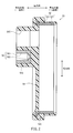
- FIG. 2 is a cross-sectional view of the cover.
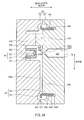
- FIG. 3A is a cross-sectional view illustrating a method for manufacturing a cover, and is a cross-sectional view illustrating a state in which a nut and a core metal are disposed in a cavity formed in a mold.
- FIG. 3B is a cross-sectional view illustrating a cover manufacturing method, and is a cross-sectional view illustrating a state in which a resin material is injected into a mold.
- 4 is an enlarged cross-sectional view of a part of FIG. 3A.
- FIG. 5 is a cross-sectional view showing a state in which the resin material is injected toward the nut.
- 6 is a cross-sectional view showing a state in which a nut different from the nut shown in FIG. 2 is supported by a protrusion formed on the mold.
- the cover manufacturing method is a method for manufacturing a cover attached to the outer ring of the hub unit.
- the manufacturing method includes the following step (A), step (B), step (C), step (D) and step (E).
- step (A) a first mold having a protrusion protruding into a first recess that forms a part of a cavity filled with a resin material is prepared.
- step (B) a second mold having a gate that opens into a second recess forming another part of the cavity and through which a resin material filled in the cavity passes is prepared.
- the nut is supported by the protrusion formed on the first mold.
- step (D) the first mold and the second mold are matched with each other in a state where at least a part of the gate overlaps inside the outer peripheral surface of the nut when viewed from the axial direction of the nut.
- step (E) a resin material is injected into a cavity formed in a state where the first mold and the second mold are combined.
- the nut can be pressed by the resin material injected from the gate. Therefore, unlike the prior art, there is no need to hold down the nut with a pin arranged so as to be able to advance and retract toward the nut. As a result, it is possible to avoid a complicated mold structure.
- the nut is not only a screw groove formed in the inner peripheral surface of the hole into which the bolt is inserted before the resin material is injected, but also after the resin material is injected.
- a screw groove is formed on the inner peripheral surface of the hole into which the bolt is inserted.
- the nut includes a tube portion and a stopper.
- Bolts are inserted into the cylindrical portion.
- the stopper covers the opening on one end side in the axial direction of the cylindrical portion, and regulates the insertion amount of the bolt by contacting with the bolt inserted into the cylindrical portion.
- the opening to the gate cavity overlaps the stopper.
- the nut when viewed from the axial direction of the nut, the opening to the gate cavity overlaps the stopper.
- the nut is less likely to wobble in the direction intersecting the axial direction.
- the entire opening to the cavity of the gate overlaps the stopper.
- the nut when viewed from the axial direction of the nut, the entire opening to the cavity of the gate overlaps the stopper.
- the nut when the nut is pressed by the resin material injected from the gate, the nut is less likely to wobble in the direction intersecting the axial direction.
- the center of the opening to the gate cavity coincides with the center of the stopper.
- the nut when viewed from the axial direction of the nut, the center of the opening to the gate cavity coincides with the center of the stopper.
- the nut when the nut is pressed by the resin material injected from the gate, the nut is less likely to wobble in the direction intersecting the axial direction.
- FIG. 1 shows a hub unit 10 to which a cover manufactured by a manufacturing method according to an embodiment of the present invention is attached.
- the axial direction is a direction in which the central axis CL of the hub unit 10 extends.
- the radial direction is a direction perpendicular to the central axis CL, that is, a direction perpendicular to the axial direction.
- the circumferential direction is a direction around the central axis CL.
- one end side in the axial direction of the hub unit 10 corresponds to the inside of the vehicle, and the other end side in the axial direction of the hub unit 10 (in FIG. 1).
- the right end side corresponds to the outside of the vehicle.
- the hub unit 10 includes an outer ring 12, an inner shaft 14, an inner ring 16, a plurality of rolling elements 18, a plurality of rolling elements 20, a cage 22, and a cage 24. including.
- these members will be described.
- the outer ring 12 has a cylindrical shape. Two raceway surfaces 121 and 122 are formed on the inner peripheral surface of the outer ring 12.
- the outer ring 12 is fixed to a suspension device, for example.
- the inner shaft 14 is disposed inside the outer ring 12 and is positioned coaxially with the outer ring 12.
- the inner shaft 14 is disposed so as to be rotatable in the circumferential direction with respect to the outer ring 12.
- the inner shaft 14 has a raceway surface 141.
- the raceway surface 141 is formed on the outer peripheral surface of the inner shaft 14.
- the inner shaft 14 further has a flange 142.
- the flange 142 is formed continuously in the circumferential direction.
- a plurality of holes are formed in the flange 142.
- the plurality of holes are positioned at equal intervals in the circumferential direction.
- a wheel (specifically, a wheel), a brake disk, or the like is attached to the inner shaft 14 by a bolt inserted into each of the plurality of holes.
- the inner ring 16 has a cylindrical shape.
- the inner ring 16 is fixed to the inner shaft 14. Specifically, in a state where the inner shaft 14 is press-fitted into the inner ring 16, the inner ring 16 is caulked and fixed to the inner shaft 14 by a caulking portion 143 formed at the left end (one axial end) of the inner shaft 14.
- the inner ring 16 includes a raceway surface 161.
- the raceway surface 161 is formed on the outer peripheral surface of the inner ring 16.
- the plurality of rolling elements 18 are disposed between the outer ring 12 and the inner shaft 14.
- the plurality of rolling elements 18 are arranged at equal intervals in the circumferential direction by the cage 22.
- Each of the plurality of rolling elements 18 contacts the raceway surface 121 and the raceway surface 141.
- the plurality of rolling elements 20 are disposed between the outer ring 12 and the inner ring 16.
- the plurality of rolling elements 20 are arranged at equal intervals in the circumferential direction by the cage 24.
- Each of the plurality of rolling elements 20 contacts the raceway surface 122 and the raceway surface 161.
- Pulsar ring A pulsar ring 28 is fixed to the inner ring 16 via a metal core 30 in the hub unit 10.
- the core metal 30 includes a cylindrical portion 301 and an annular plate portion 302.
- the cylinder part 301 has a cylindrical shape.
- An annular plate 302 is disposed at the left end (one axial end) of the cylindrical portion 301.
- the annular plate portion 302 has an annular plate shape.
- the outer peripheral edge of the annular plate portion 302 is formed integrally with the left end (one axial end) of the cylindrical portion 301.
- the pulsar ring 28 is fixed to one surface in the thickness direction of the annular plate portion 302 (the left end surface in FIG. 1). As a method for fixing the pulsar ring 28 to the annular plate portion 302, for example, there is adhesion.
- the pulsar ring 28 is alternately magnetized with N and S poles in the circumferential direction.
- a cover 50 is fixed to the cover hub unit 10.
- the cover 50 will be described with reference to FIG.
- the cover 50 includes a cored bar 52, a cover main body 54, and a nut 56.
- the cored bar 52 is made of metal.
- the cored bar 52 includes a cylindrical part 521 and a flange part 522.
- the cylinder part 521 has a cylindrical shape.
- a flange portion 522 is disposed at the left end (one axial end) of the cylindrical portion 521.
- the flange portion 522 has an annular plate shape.
- the inner peripheral edge of the flange portion 522 is formed integrally with the left end (one axial end) of the cylindrical portion 521.
- the cover body 54 is disposed at the left end (one end in the axial direction) of the cylindrical portion 521.
- the cover main body 54 is made of a synthetic resin.
- the cover main body 54 has a disk shape.
- the outer peripheral edge of the cover main body 54 is connected to the left end (one end in the axial direction) of the cylindrical portion 521 over the entire periphery. That is, the cover main body 54 covers the opening at the left end (one axial end) of the cylindrical portion 521.
- the cover body 54 includes a covering portion 541.
- the covering portion 541 is located on the outer peripheral edge portion of the cover main body 54.
- the covering portion 541 is formed over the entire circumference.
- the covering portion 541 covers both sides in the thickness direction of the flange portion 522 (left and right end surfaces in FIG. 2) over the entire circumference. In other words, the flange portion 522 is embedded in the covering portion 541.
- the covering portion 541 covers the outer peripheral surface of the cylindrical portion 521 over the entire circumference.
- the cover body 54 includes a mounting portion 542.
- the attachment portion 542 protrudes from the cover body 54 toward the left side (one axial end side).
- the attachment portion 542 extends in the axial direction with a substantially constant cross-sectional shape.
- An insertion hole 543 is formed in the cover body 54 at a position where the attachment portion 542 is formed.
- the insertion hole 543 extends in the axial direction and has a cylindrical inner peripheral surface.
- the insertion hole 543 is formed so as to penetrate the cover main body 54 in the axial direction.
- a nut 56 is embedded in the mounting portion 542 at a position different from the position where the insertion hole 543 is formed.
- the nut 56 includes a cylindrical portion 561 and a stopper 562.
- the cylinder part 561 has a cylindrical shape.
- a thread groove is formed on the inner peripheral surface of the cylindrical portion 561.
- the left end surface (one axial end surface) of the cylindrical portion 561 is exposed. That is, the left end surface (one axial end surface) of the cylindrical portion 561 is not covered with the attachment portion 542 in a state where the nut 56 is embedded in the attachment portion 542.
- the stopper 562 is formed at the right end (the other end in the axial direction) of the cylindrical portion 561.
- the stopper 562 has a disc shape and defines the right end (end on the other end side in the axial direction) of the hole of the cylindrical portion 561.
- die 60 (refer FIG. 3A) used for manufacture of the cover 50 is prepared. Subsequently, as shown in FIG. 3A, the core metal 52 and the nut 56 are arranged in the mold 60.
- the mold 60 includes a mold 62 as a first mold and a mold 64 as a second mold.
- a cavity 60 ⁇ / b> A is formed in the mold 60 by aligning the mold 62 and the mold 64.
- the left-right direction in the figure is the mold alignment direction of the mold 62 and the mold 64.
- the mold 62 has a recess 621 as a first recess.
- the concave portion 621 opens in the mold matching surface 622 of the mold 62 with the mold 64.
- the recess 621 opens toward the mold 64.
- the recess 621 is open in the mold alignment direction.
- An end face 623 is formed in the recess 621.
- the end surface 623 is at a position farthest from the mold matching surface 622.
- the end surface 623 defines the end of the recess 621 in the mold alignment direction.
- the end surface 623 has a shape corresponding to the front end surface of the attachment portion 542 of the cover 50.
- a protrusion 62A and a protrusion 62B are arranged in the recess 621.
- the protrusion 62A protrudes from the end surface 623 toward the mold 64.
- the protrusion 62A protrudes from the end surface 623 in the mold matching direction.
- the protrusion 62A has a cylindrical shape. That is, the protrusion 62A has a substantially constant diameter and extends in the mold matching direction.
- the protrusion 62A has a circular tip surface 62A1.
- the protrusion 62A is inserted into the cylindrical portion 561 of the nut 56. In this state, the tip surface of the protrusion 62 ⁇ / b> A is in contact with the stopper 562 of the nut 56.
- the protrusion 62B is formed at a position different from the protrusion 62A.
- the protrusion 62B protrudes from the end surface 623 toward the mold 64.
- the protrusion 62B protrudes from the end surface 623 in the mold matching direction.
- the protrusion 62B has a cylindrical shape. That is, the protrusion 62B has a substantially constant diameter and extends in the mold matching direction.
- the protrusion 62B has a circular tip surface. The diameter of the protrusion 62B is larger than the diameter of the protrusion 62A.
- the mold 64 has a recess 641 as a second recess.
- the concave portion 641 is opened in the mold matching surface 642 of the mold 64 with the mold 62.
- the recess 641 opens toward the mold 62.
- the recess 641 is open in the mold alignment direction.
- the recess 641 has an end face 643.
- the end face 643 is located at the position farthest from the mold matching face 642. In short, the end surface 643 defines the end of the recess 641 in the mold alignment direction.
- a protrusion 64 ⁇ / b> A is disposed in the recess 641.
- the protrusion 64A protrudes from the end face 643 toward the mold 62.
- the protrusion 64A protrudes from the end face 643 in the mold matching direction.
- the protrusion 64A has a cylindrical shape.
- the protrusion 64A has an outer peripheral surface 64A1, a step surface 64A2, and an outer peripheral surface 64A3.
- the outer peripheral surface 64A1 is a cylindrical surface having a substantially constant diameter and extending straight in the mold alignment direction.
- the outer peripheral surface 64A3 is a cylindrical surface having a substantially constant diameter and extending straight in the mold alignment direction.
- the diameter of the outer peripheral surface 64A3 is larger than the diameter of the outer peripheral surface 64A1.
- the step surface 64A2 is an annular surface.
- the inner peripheral end of the step surface 64A2 is connected to the right end of the outer peripheral surface 64A1 (the end away from the mold alignment surface 642 in the mold alignment direction).
- the outer peripheral end of the step surface 64A2 is connected to the left end of the outer peripheral surface 64A3 (the end closer to the mold alignment surface 642 in the mold alignment direction).
- the protrusion 64A has a tip surface 64A4.
- the tip surface 64A4 has a circular shape.
- a protrusion 64B is formed on the tip surface 64A4.
- the protrusion 64B protrudes from the distal end surface 64A4 toward the mold 62.
- the protrusion 64B protrudes from the tip end face 64A4 in the mold matching direction.
- the protrusion 64B has a cylindrical shape. That is, the protrusion 64B extends in the mold matching direction with a substantially constant diameter.
- the protrusion 64B has a circular tip surface. In a state where the mold 62 and the mold 64 are matched with each other, the protrusion 64B is positioned coaxially with the protrusion 62B. The tip surface of the protrusion 64B overlaps the tip surface of the protrusion 62B.
- the protrusion 64A is inserted into the cylindrical portion 521 of the cored bar 52.
- the right end (the other end in the axial direction) of the cylindrical portion 521 is in contact with the step surface 64A2. That is, the insertion amount of the cylindrical portion 521 is defined by the step surface 64A2.
- the mold 64 has an accommodation recess 64C.
- the housing recess 64C is formed at a position where the protrusion 64A is formed.
- the accommodation recess 64C opens in a direction opposite to the direction in which the protrusion 64A protrudes.
- the distal end portion of the hot runner nozzle 70 is accommodated in the accommodating recess 64C.
- a cylindrical inner peripheral surface 64C1 and a tapered cylindrical inner peripheral surface 64C2 are formed in the housing recess 64C.
- the right end of the inner peripheral surface 64C2 (the end farther from the mold alignment surface 642 in the mold alignment direction) is connected to the left end of the inner peripheral surface 64C1 (the end closer to the mold alignment surface 642 in the mold alignment direction). Yes.
- the inner peripheral surface 64C1 has a substantially constant diameter and extends straight in the mold matching direction.
- the right end of the inner peripheral surface 64C1 (the end away from the mold alignment surface 642 in the mold alignment direction) defines the opening end of the housing recess 64C.
- the diameter of the inner peripheral surface 64C2 is smaller at the end away from the inner peripheral surface 64C1 than at the end connected to the inner peripheral surface 64C1.
- the gate 64D is formed in the mold 64.
- the gate 64D has a cylindrical inner peripheral surface. That is, the gate 64D has a substantially constant diameter and extends straight in the mold alignment direction.
- the right end of the gate 64D (the end away from the mold matching surface 642) is connected to the housing recess 64C (specifically, the small diameter end of the inner peripheral surface 64C2).
- the left end of the gate 64D (the end closer to the mold matching surface 642) is open to the tip end surface 64A4 of the protrusion 64A.
- the center (center in the radial direction) of the gate 64D coincides with the center (center in the radial direction) of the protrusion 62A. ing. That is, the gate 64D is located coaxially with the protrusion 62A formed on the mold 62.
- the center (diameter center) of the nut 56 coincides with the center (diameter center) of the gate 64D. That is, the gate 64D is located coaxially with the nut 56.
- the gate 64D is formed at a position overlapping the stopper 562 of the nut 56 when viewed from the mold alignment direction. That is, the gate 64 ⁇ / b> D is formed at a position overlapping the inner region of the outer peripheral surface of the cylindrical portion 561 of the nut 56 when viewed from the mold alignment direction.
- a cavity 60 ⁇ / b> A is formed in the mold 60 by aligning the mold 62 and the mold 64.
- a resin material is injected into the cavity 60A.
- the resin material is injected into the cavity 60A through the gate 64D.
- the injected resin material is filled in the cavity 60A.
- the resin material When injected into the cavity 60A, the resin material hits the stopper 562 of the nut 56 as shown in FIG.
- the stopper 562 is pressed against the tip surface of the protrusion 62A by the pressure when the resin material is injected. Therefore, the nut 56 can be prevented from coming out of the protrusion 62A.
- the resin material that has hit the stopper 562 covers the end face in the axial direction of the nut 56, and then wraps around the radially outer side of the nut 56 to cover the outer peripheral face of the nut 56. That is, the nut 56 can be prevented from moving in the radial direction with respect to the protrusion 62A. In this manner, the nut 56 can be positioned by covering the axial end surface and the outer peripheral surface of the nut 56 with the resin material.
- the cover 50 As a molded product is obtained. After separating the mold 62 from the mold 64, the cover 50 is taken out from the mold 64 by using a plurality of ejector pins.
- the cover 50 is assembled to the hub unit 10 by inserting the cylindrical portion 521 of the cored bar 52 into the outer ring 12 of the hub unit 10.
- a sensor 40 that detects the rotation of the inner shaft 14 is attached to the cover 50.
- the sensor 40 is inserted into the insertion hole 543 formed in the cover 50.
- the mounting portion 40 ⁇ / b> A provided in the sensor 40 is overlaid on the end surface of the mounting portion 542, and is fixed to the mounting portion 542 of the cover 50 by a bolt 42 inserted into the nut 56.
- the nut 56 is positioned using the pressure when the resin material is injected. Therefore, the structure of the metal mold 64 can be simplified as compared with the case where a pin that can be moved back and forth with respect to the nut 56 is arranged in the metal mold 64 and the nut 56 is pushed by the pin.
- the gate 64D is positioned coaxially with the nut 56. Therefore, when the nut 56 is pressed against the protrusion 62A by the resin material injected from the gate 64D, the nut 56 is less likely to wobble in the radial direction of the cylindrical portion 561. As a result, it is possible to avoid the resin material from hardening in a state where the nut 56 is inclined with respect to the protrusion 62A.
- the nut 56 is provided with the stopper 562, but may not be provided with the stopper 562.
- FIG. 6 shows a state in which the nut 56 ⁇ / b> A not provided with the stopper 562 is arranged in the mold 60.
- the resin material injected from the gate 64D hits the tip surface of the protrusion 62A. Due to the pressure at the time of injection, the resin material hitting the tip surface of the protrusion 62A spreads in the radial direction of the protrusion 62A.
- the axial end surface (the right end surface in FIG. 6) of the cylindrical portion 561 of the nut 56A is covered with the resin material.
- the nut 56A can be prevented from coming out of the protrusion 62A. Further, the resin material covering the axial end surface of the cylindrical portion 561 then wraps around the radially outer side of the cylindrical portion 561 and covers the outer peripheral surface of the cylindrical portion 561. That is, the nut 56A can be prevented from moving in the radial direction of the cylindrical portion 561 with respect to the protrusion 62A. In this way, the nut 56A can be positioned by covering the axial end surface and the outer peripheral surface of the cylindrical portion 561 with the resin material.
- a thread groove may not be formed in advance on the inner peripheral surface of the cylindrical portion 561.
- a thread groove may be formed on the inner peripheral surface of the cylindrical portion 561.
- the resin that has entered the thread groove may be scraped off.
- the gate 64D may not be positioned coaxially with the protrusion 62A.
- the gate 64D may be formed at a position overlapping the axial end surface of the cylindrical portion 561 when viewed from the mold alignment direction. In this case, the resin material injected from the hot runner nozzle 70 can hit the nut 56A. As a result, the nut 56A can be positioned more reliably.
- the gate 64D may not be positioned coaxially with the nut 56. It suffices that at least a part of the gate 64D overlaps the nut 56 when viewed from the mold alignment direction of the mold 62 and the mold 64.
Landscapes
- Engineering & Computer Science (AREA)
- Mechanical Engineering (AREA)
- General Engineering & Computer Science (AREA)
- Manufacturing & Machinery (AREA)
- Moulds For Moulding Plastics Or The Like (AREA)
- Injection Moulding Of Plastics Or The Like (AREA)
- Rolling Contact Bearings (AREA)
- Sealing Of Bearings (AREA)
Abstract
Description
図1は、本発明の実施の形態による製造方法で製造されるカバーが取り付けられたハブユニット10を示す。なお、以下の説明において、軸方向は、ハブユニット10の中心軸線CLが延びる方向である。径方向は、中心軸線CLに垂直な方向、つまり、軸方向に垂直な方向である。周方向は、中心軸線CL周りの方向である。ハブユニット10が車両に配置された状態では、ハブユニット10の軸方向一端側(図1中の左端側)が車両の内側に相当し、ハブユニット10の軸方向他端側(図1中の右端側)が車両の外側に相当する。
図1を参照して、ハブユニット10は、外輪12と、内軸14と、内輪16と、複数の転動体18と、複数の転動体20と、保持器22と、保持器24とを含む。以下、これらの部材について説明する。
ハブユニット10には、パルサリング28が、芯金30を介して、内輪16に固定されている。
ハブユニット10には、カバー50が固定されている。図2を参照しながら、カバー50について説明する。カバー50は、芯金52と、カバー本体54と、ナット56とを備える。
続いて、カバー50の製造方法について説明する。先ず、カバー50の製造に用いる金型60(図3A参照)を準備する。続いて、図3Aに示すように、金型60内に、芯金52及びナット56を配置する。
上記実施の形態では、ナット56は、ストッパ562を備えていたが、ストッパ562を備えていなくてもよい。図6は、ストッパ562を備えていないナット56Aが金型60内に配置された状態を示している。この場合、ゲート64Dから射出される樹脂材料は、突起62Aの先端面にぶつかる。射出時の圧力により、突起62Aの先端面にぶつかった樹脂材料は、突起62Aの径方向に広がる。その結果、ナット56Aの筒部561の軸方向端面(図6中の右端面)が、樹脂材料で覆われる。つまり、ナット56Aが突起62Aから抜け出すのを阻止することができる。また、筒部561の軸方向端面を覆った樹脂材料は、その後、筒部561の径方向外側に回り込み、筒部561の外周面を覆う。つまり、ナット56Aが、突起62Aに対して、筒部561の径方向に移動するのを阻止することができる。このようにして、筒部561の軸方向端面及び外周面を樹脂材料で覆うことにより、ナット56Aを位置決めすることができる。
Claims (5)
- ハブユニットの外輪に取り付けられるカバーの製造方法であって、
樹脂材料が充填されるキャビティの一部を形成する第1凹部内に突出する突起を有する第1金型を準備し、
前記キャビティの他の一部を形成する第2凹部内に開口し、前記キャビティに充填される前記樹脂材料が通過するゲートを有する第2金型を準備し、
前記突起により、ナットを支持し、
前記ナットの軸方向から見たときに、前記ナットの外周面よりも内側に前記ゲートの少なくとも一部が重なっている状態で、前記第1金型と前記第2金型とを型合わせし、
前記第1金型と前記第2金型とが型合わせされた状態で形成される前記キャビティ内に、前記樹脂材料を射出する、
ことを備える、カバーの製造方法。 - 請求項1に記載のカバーの製造方法であって、
前記ナットは、
ボルトが挿入される筒部と、
前記筒部の軸方向一端側の開口を覆い、前記ボルトの挿入量を規定するストッパと
を含む、カバーの製造方法。 - 請求項2に記載のカバーの製造方法であって、
前記軸方向から見て、前記ゲートの前記キャビティへの開口が、前記ストッパに重なる、カバーの製造方法。 - 請求項3に記載のカバーの製造方法であって、
前記軸方向から見て、前記ゲートの前記キャビティへの開口の全体が、前記ストッパに重なる、カバーの製造方法。 - 請求項1~4の何れか1項に記載のカバーの製造方法であって、
前記軸方向から見て、前記ゲートの前記キャビティへの開口の中心が、前記筒部の中心軸線上に位置している、カバーの製造方法。
Priority Applications (4)
| Application Number | Priority Date | Filing Date | Title |
|---|---|---|---|
| KR1020187013429A KR20180082447A (ko) | 2015-11-13 | 2016-11-10 | 커버 생산 방법 |
| US15/775,698 US20180345550A1 (en) | 2015-11-13 | 2016-11-10 | Production method for cover |
| DE112016005203.0T DE112016005203T5 (de) | 2015-11-13 | 2016-11-10 | Fertigungsverfahren für eine Abdeckung |
| CN201680066840.5A CN108290327B (zh) | 2015-11-13 | 2016-11-10 | 盖的生产方法 |
Applications Claiming Priority (2)
| Application Number | Priority Date | Filing Date | Title |
|---|---|---|---|
| JP2015-223008 | 2015-11-13 | ||
| JP2015223008A JP6661987B2 (ja) | 2015-11-13 | 2015-11-13 | カバーの製造方法 |
Publications (1)
| Publication Number | Publication Date |
|---|---|
| WO2017082328A1 true WO2017082328A1 (ja) | 2017-05-18 |
Family
ID=58695537
Family Applications (1)
| Application Number | Title | Priority Date | Filing Date |
|---|---|---|---|
| PCT/JP2016/083313 Ceased WO2017082328A1 (ja) | 2015-11-13 | 2016-11-10 | カバーの製造方法 |
Country Status (6)
| Country | Link |
|---|---|
| US (1) | US20180345550A1 (ja) |
| JP (1) | JP6661987B2 (ja) |
| KR (1) | KR20180082447A (ja) |
| CN (1) | CN108290327B (ja) |
| DE (1) | DE112016005203T5 (ja) |
| WO (1) | WO2017082328A1 (ja) |
Cited By (2)
| Publication number | Priority date | Publication date | Assignee | Title |
|---|---|---|---|---|
| US20220032513A1 (en) * | 2018-12-06 | 2022-02-03 | Mitsubishi Heavy Industries, Ltd. | Production device for composite material structure, composite material structure produced by production device, and method for producing composite material structure |
| US11333207B2 (en) | 2018-05-09 | 2022-05-17 | Horton, Inc. | Shaft output viscous clutch |
Families Citing this family (1)
| Publication number | Priority date | Publication date | Assignee | Title |
|---|---|---|---|---|
| WO2020045072A1 (ja) * | 2018-08-29 | 2020-03-05 | Nok株式会社 | シール部材の製造方法および成形型 |
Citations (5)
| Publication number | Priority date | Publication date | Assignee | Title |
|---|---|---|---|---|
| JPS5539866U (ja) * | 1978-09-07 | 1980-03-14 | ||
| JPH02266908A (ja) * | 1989-04-07 | 1990-10-31 | Man Design Kk | 円筒形樹脂製品の成型方法及び同樹脂製品の成型用雄金型 |
| JP2006321061A (ja) * | 2005-05-17 | 2006-11-30 | Nakanishi Metal Works Co Ltd | インサート成形品の製造方法 |
| JP2008115759A (ja) * | 2006-11-02 | 2008-05-22 | Sigma Kk | インペラ |
| JP2011161757A (ja) * | 2010-02-09 | 2011-08-25 | Kyb Co Ltd | 保護キャップ及びその製造方法 |
Family Cites Families (6)
| Publication number | Priority date | Publication date | Assignee | Title |
|---|---|---|---|---|
| JP2000343567A (ja) * | 1999-06-07 | 2000-12-12 | Sony Corp | 円盤状記録媒体基板の成形金型装置 |
| JP4375206B2 (ja) * | 2004-11-16 | 2009-12-02 | 住友電装株式会社 | インサート成形品及びインサート成形品の製造方法 |
| JP2015223008A (ja) | 2012-09-18 | 2015-12-10 | 三洋電機株式会社 | 電源装置及びこの電源装置を備える電動車両並びに蓄電装置 |
| JP5623592B2 (ja) | 2013-05-20 | 2014-11-12 | Ntn株式会社 | 回転速度検出装置付き車輪用軸受装置用のセンサキャップおよびこれを備えた回転速度検出装置付き車輪用軸受装置および回転速度検出装置付き車輪用軸受装置用のセンサキャップの製造方法 |
| US20160244040A1 (en) * | 2015-02-23 | 2016-08-25 | Nakanishi Metal Works Co., Ltd. | Insert molded article, manufacturing method for protective cover having sensor holder part, and manufacturing method for bearing device including the protective cover |
| TWI581938B (zh) * | 2015-06-12 | 2017-05-11 | 廣達電腦股份有限公司 | 自動化埋釘射出成型系統及其方法 |
-
2015
- 2015-11-13 JP JP2015223008A patent/JP6661987B2/ja not_active Expired - Fee Related
-
2016
- 2016-11-10 US US15/775,698 patent/US20180345550A1/en not_active Abandoned
- 2016-11-10 DE DE112016005203.0T patent/DE112016005203T5/de not_active Withdrawn
- 2016-11-10 KR KR1020187013429A patent/KR20180082447A/ko not_active Ceased
- 2016-11-10 CN CN201680066840.5A patent/CN108290327B/zh not_active Expired - Fee Related
- 2016-11-10 WO PCT/JP2016/083313 patent/WO2017082328A1/ja not_active Ceased
Patent Citations (5)
| Publication number | Priority date | Publication date | Assignee | Title |
|---|---|---|---|---|
| JPS5539866U (ja) * | 1978-09-07 | 1980-03-14 | ||
| JPH02266908A (ja) * | 1989-04-07 | 1990-10-31 | Man Design Kk | 円筒形樹脂製品の成型方法及び同樹脂製品の成型用雄金型 |
| JP2006321061A (ja) * | 2005-05-17 | 2006-11-30 | Nakanishi Metal Works Co Ltd | インサート成形品の製造方法 |
| JP2008115759A (ja) * | 2006-11-02 | 2008-05-22 | Sigma Kk | インペラ |
| JP2011161757A (ja) * | 2010-02-09 | 2011-08-25 | Kyb Co Ltd | 保護キャップ及びその製造方法 |
Cited By (2)
| Publication number | Priority date | Publication date | Assignee | Title |
|---|---|---|---|---|
| US11333207B2 (en) | 2018-05-09 | 2022-05-17 | Horton, Inc. | Shaft output viscous clutch |
| US20220032513A1 (en) * | 2018-12-06 | 2022-02-03 | Mitsubishi Heavy Industries, Ltd. | Production device for composite material structure, composite material structure produced by production device, and method for producing composite material structure |
Also Published As
| Publication number | Publication date |
|---|---|
| JP2017089822A (ja) | 2017-05-25 |
| CN108290327B (zh) | 2021-05-28 |
| KR20180082447A (ko) | 2018-07-18 |
| US20180345550A1 (en) | 2018-12-06 |
| JP6661987B2 (ja) | 2020-03-11 |
| DE112016005203T5 (de) | 2018-07-26 |
| CN108290327A (zh) | 2018-07-17 |
Similar Documents
| Publication | Publication Date | Title |
|---|---|---|
| JP4747754B2 (ja) | モータ | |
| US8516922B2 (en) | Bicycle pedal assembly | |
| JP6589585B2 (ja) | カバーの製造方法 | |
| JP6661987B2 (ja) | カバーの製造方法 | |
| EP1614548B1 (en) | Hub body for a bicycle wheel and hub comprising such a hub body | |
| US8210750B2 (en) | Vehicle bearing assembly | |
| EP3816480B1 (en) | Ball screw nut, electric power steering device , and method for manufacturing ball screw nut | |
| JP2003013982A (ja) | エンコーダ付軸受ユニット | |
| JP7107032B2 (ja) | センサユニット付軸受キャップ及びハブユニット軸受 | |
| US11472468B2 (en) | Power steering apparatus | |
| US9464706B2 (en) | Shaft with a gear cast on its front side and method for producing such a shaft | |
| JP4747853B2 (ja) | 転がり軸受装置用センサ付きシール装置の固定側シール部材とその製造方法 | |
| JP5949178B2 (ja) | トルク検出装置用ヨーク組立体及びその製造方法 | |
| JP2017015246A (ja) | センサホルダ部を有する保護カバー、及び前記保護カバーを備えた軸受装置、並びにセンサホルダ部を有する保護カバーの製造方法 | |
| JP4812615B2 (ja) | ボールジョイント及びボールジョイントの製造方法 | |
| JP7230681B2 (ja) | センサホルダ部を有する保護カバー、及び前記保護カバーを備えた軸受装置、並びにセンサホルダ部を有する保護カバーの製造方法 | |
| WO2008146998A1 (en) | Automobile abs tone wheel sensor and manufacture method | |
| JP7826846B2 (ja) | アンギュラ玉軸受用冠型保持器の製造方法、及びアンギュラ玉軸受用冠型保持器 | |
| JP5346610B2 (ja) | ボールジョイント、及び、ベアリングシートの製造方法 | |
| JP5949320B2 (ja) | トルク検出装置用ヨーク組立体及びその製造方法 | |
| JP7414754B2 (ja) | 電動パワーステアリング装置、ナットとプーリの固定構造および電動パワーステアリング装置の製造方法 | |
| JP2024132725A (ja) | センサホルダおよび車輪用軸受装置 | |
| IT202300008781A1 (it) | Dispositivo coprimozzo flottante per una ruota di un veicolo | |
| JP2020076661A (ja) | ヨーク組立体、及びトルク検出装置、並びにヨーク組立体の製造方法 | |
| JP2004001553A (ja) | 樹脂成形品 |
Legal Events
| Date | Code | Title | Description |
|---|---|---|---|
| 121 | Ep: the epo has been informed by wipo that ep was designated in this application |
Ref document number: 16864289 Country of ref document: EP Kind code of ref document: A1 |
|
| ENP | Entry into the national phase |
Ref document number: 20187013429 Country of ref document: KR Kind code of ref document: A |
|
| WWE | Wipo information: entry into national phase |
Ref document number: 112016005203 Country of ref document: DE |
|
| 122 | Ep: pct application non-entry in european phase |
Ref document number: 16864289 Country of ref document: EP Kind code of ref document: A1 |