WO2017081986A1 - 物体検出装置 - Google Patents
物体検出装置 Download PDFInfo
- Publication number
- WO2017081986A1 WO2017081986A1 PCT/JP2016/080638 JP2016080638W WO2017081986A1 WO 2017081986 A1 WO2017081986 A1 WO 2017081986A1 JP 2016080638 W JP2016080638 W JP 2016080638W WO 2017081986 A1 WO2017081986 A1 WO 2017081986A1
- Authority
- WO
- WIPO (PCT)
- Prior art keywords
- processing
- image
- object detection
- processing unit
- vehicle
- Prior art date
- Legal status (The legal status is an assumption and is not a legal conclusion. Google has not performed a legal analysis and makes no representation as to the accuracy of the status listed.)
- Ceased
Links
Images





Classifications
-
- G—PHYSICS
- G06—COMPUTING OR CALCULATING; COUNTING
- G06T—IMAGE DATA PROCESSING OR GENERATION, IN GENERAL
- G06T7/00—Image analysis
-
- G—PHYSICS
- G08—SIGNALLING
- G08G—TRAFFIC CONTROL SYSTEMS
- G08G1/00—Traffic control systems for road vehicles
- G08G1/16—Anti-collision systems
Definitions
- the present invention relates to an in-vehicle image processing apparatus.
- Patent Document 1 discloses an in-vehicle multi-application execution device, which describes a function of detecting a pedestrian or a vehicle as an object.
- an in-vehicle multi-application execution device which describes a function of detecting a pedestrian or a vehicle as an object.
- the configuration and operation of a so-called multi-CPU having a plurality of processing devices are also described.
- Patent Document 1 it is proposed to assign a CPU to each recognition application for recognizing an object.
- the present invention can suppress a bottleneck when each processing device accesses a storage device for object identification processing in an in-vehicle image processing device including a plurality of processing devices, and can speed up the processing.
- An object is to provide an in-vehicle image processing apparatus.
- the present invention provides a first processing unit that assigns distance information to an image element constituting an image acquired from an imaging unit and sets a plurality of processing regions using the distance information, and a processing region to be identified Is assigned using the distance information, and includes a second processing unit having a plurality of processing devices that perform the object identification processing on the assigned processing region.
- the present invention provides a first processing unit that sets a plurality of processing regions for an image acquired from an imaging unit, a plurality of storage devices that store different processing regions among the plurality of processing regions, A second processing unit having a plurality of processing devices that respectively access the plurality of storage devices and perform image processing on the processing areas stored in the respective storage devices.
- a vehicle-mounted image processing device including a plurality of processing devices, it is possible to suppress bottlenecks when each processing device accesses a storage device for object identification processing, and to speed up processing. .
- FIG. 1 shows the basic configuration of the device.
- the sensor 100 includes a camera that acquires an image of the outside world, a device that acquires distance information 155 corresponding to the image, and a gradient sensor, an acceleration sensor, and a GPS device as necessary.
- a device for acquiring the distance information 155 is arbitrary, and for example, a laser radar or a millimeter wave radar can be used. Further, a method of acquiring a distance from parallax information using a camera as a stereo camera configuration can also be used.
- the distance information acquisition processing unit 200 obtains actual distance information 155 from the data acquired by the sensor 100 and associates it with an image acquired from the camera.
- the distance information acquisition processing unit 200 also calculates additional data commonly used in subsequent object detection processing (for example, an edge image).
- the assignment control parameter 400 is a condition for assigning the object detection CPU core based on the data calculated by the distance information acquisition processing unit 200. This condition may be fixed. However, for example, it is conceivable to change dynamically based on information from the gradient sensor.
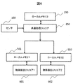
- the CPU core assignment processing unit 300 is a first object detection CPU core 601 or a second object detection CPU core that finally performs object detection processing on various data coming from the distance information acquisition unit 200 based on the assignment control parameter 400.
- the first local memory 501 is a storage device that is used when the first object detection CPU core 601 receives necessary data from the CPU core assignment processing unit 300 and the first object detection CPU core 601 performs arithmetic processing.
- the second local memory 502 is a storage device that is used when the second object detection CPU core 602 receives necessary data from the CPU core assignment processing unit 300 and the second object detection CPU core 602 performs arithmetic processing. .
- the first object detection CPU core 601 and the second object detection CPU core 602 perform arithmetic processing on the image elements assigned by the CPU core assignment processing unit (300), and finally, at what position in the space It is a CPU core that detects whether an object exists.
- the object detection result is output to the outside via an input / output interface such as a vehicle network (CAN) interface.
- CAN vehicle network
- a local memory and an object detection CPU core are added as a set.
- By preparing a local memory that is tightly coupled to each object detection CPU core it is possible to improve the memory access bandwidth necessary for the calculation process in parallel with the improvement of the calculation performance required for the object detection process, A bottleneck associated with insufficient memory access bandwidth can be prevented. Since the computing performance and the memory access bandwidth can be improved at the same time, the performance and functional scalability of the apparatus are improved.
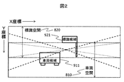
- FIG. 2 is an image viewed from the upper center of the windshield of the vehicle, that is, an image that can be acquired by the camera of the object detection device
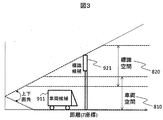
- FIG. 3 is a cross-sectional view of the space corresponding to the image of FIG.
- the space that can be monitored by the sensor 100 is divided into a sign space 820 and a vehicle space 810 as shown in FIGS.
- the sign space 820 is a space intended for an object existing above the space
- the vehicle space 810 is a space intended for an object present below the space.
- the sign space 820 and the vehicle space 810 will be described, and the spaces are intended for detection and identification of objects existing in the respective space areas.
- the vehicle space 810 is also targeted for detection and identification of an object such as a person existing below the space.
- the sign space 820 corresponds to a space in which both the target object and the target object can exist.
- the vertical angle of view corresponding to the areas of the sign space 820 and the vehicle space 810 varies depending on the distance (Z coordinate).
- the height of the boundary line of the region is constant at a distance from the sensor, and the vertical angle of view becomes narrower as the distance from the sensor increases. That is, even in the range existing in FIG.
- the CPU core allocation processing unit 300 can narrow down the area where the object can be estimated (hereinafter referred to as the object existence estimation area).
- the CPU core that performs processing can be used efficiently.
- the object detection range is similarly limited about the far side also about the left-right direction.
- the ranges of the sign space 820 and the vehicle space 810 are each defined in advance as a space coordinate range and prepared as the allocation control parameter 400.
- the range of spatial coordinates is defined by the length in real space in the up, down, left, and right directions for the X coordinate direction (left and right direction) and Y coordinate direction (up and down direction) in FIG. To do.
- the range of spatial coordinates may be defined by using more coordinates or length information, such as shortening the length of the far field.
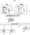
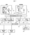
- FIG. 4 shows a processing flow of the object detection apparatus of the present invention.
- the image 150 and the distance information 155 input from the sensor 100 are first subjected to an association process 260 between the image and the distance information, and an association process between the object presence estimation region and the distance information 155 of the portion.
- the object presence estimation region detects a portion having a small difference in distance from the adjacent portion using the distance information 155 as a group of regions.
- the association processing 260 between the image 150 and the distance information 155 is performed by creating mapping information related to the coordinate relationship between the image 150 and the distance information 155 in advance and using this mapping information.
- the positional relationship between the sensor for acquiring the image 150 and the sensor for acquiring the distance information 155 shifts in the coordinate relationship between the image 150 and the distance information 155 depending on the distance corresponding to the target object existence estimation region. Therefore, the mapping to the image 150 is corrected using the distance to the object presence estimation area included in the distance information 155, and the area on the image 150 corresponding to the object existence estimation area is determined. .
- the object existence estimation area A (271) of the distance information 155 becomes the vehicle 171 and the object existence estimation area B (261) of the image 150 by the image / distance information association process 260.
- the traffic light 161 of the image 150 the object presence estimation area C (281) is associated with the sign 181 of the image 150, and the object presence estimation area D (291) is associated with the person 191 of the image 150.
- representative space coordinate calculation 320 calculates representative space coordinates for each object existence estimation region.
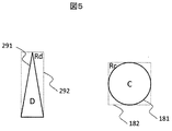
- a method of calculating the representative space coordinates will be described with reference to FIG.
- a minimum rectangle surrounding the object presence estimation area is obtained, and representative space coordinates are calculated using the center coordinates and distance information.
- the representative space coordinates of the object existence estimation area C (281) are obtained from the center coordinates of the smallest rectangle Rc (182) surrounding the object existence estimation area C (281) and the distance (20m) of the object existence estimation area C (281).
- the representative space coordinates of the object existence estimation area D (291) are calculated, the center coordinates of the smallest rectangle Rd (292) surrounding the object existence estimation area D (291) and the distance (24m) of the object existence estimation area D (291) Calculate from In the assignment determination process 310, the assignment control parameter 400 is used for each object existence estimation region obtained in the representative space coordinate calculation process 320, and the first object detection process 581 and the second object detection process 582 for performing the object detection process are assigned. And the information (the representative space coordinates, the size of the rectangle surrounding the object existence estimation area, etc.) calculated by the processing up to the area of the image 150 corresponding to the object existence estimation area, the area of the distance 250, and the assignment determination process 310 Send to the assignee.
- each object detection processing unit corresponding to the allocation control parameter 400 is collectively collected for each object detection process. It is also conceivable to send information (representative space coordinates or rectangular coordinates surrounding the object existence estimation area) for specifying the area of each object existence estimation area to the section.
- image features such as edge distribution, luminance and color distribution, area aspect ratio, pattern for each object existence estimation region It is analyzed in detail, such as the matching rate, and if the object really exists in the object estimation area, what kind of object (signals, signs, etc.) is present, and if necessary, more detailed information indicating the object Information is extracted (lighting status for traffic lights, speed limit for speed indicators, etc.).
- the second object detection processing 582 analyzes in detail the types of objects that can exist in the vehicle space 810 in the same manner as the first object detection processing 581, and whether or not the object really exists in the object estimation region. If so, what is the type of object (automobile, motorcycle, bicycle, pedestrian, white line, road markings, road surface irregularities, etc.), and if necessary, extract more detailed information from the object (whether it is a car) For example, stop lamps and turn signal display status, and for pedestrians, orientation and facial expressions).
- the object detection results of the first object detection process 581 and the second object detection process 582 are transmitted to the vehicle control computer via a network interface or the like, and can be used for safety support, driving support, and automatic driving.
- FIG. 6, FIG. 7 and FIG. 10 to FIG. 12 show hardware configuration examples for realizing the present invention.
- the sensor 100 includes a camera that acquires an image of the outside world, a device that acquires distance information corresponding to the image, and a gradient sensor, an acceleration sensor, and a GPS device as necessary.
- the common processing CPU core 250 converts the signal input from the sensor 100 into a format suitable for processing inside the apparatus, and then associates the image with distance information 260, representative space coordinate calculation processing 320, Then, an assignment determination process 310 is performed. Then, based on the result of the assignment determination process 310, information necessary for the object detection process is written in one or both of the first local memory 501 and the second local memory 502.
- the allocation control parameter 400 is implemented as a part of the common processing CPU core 250 program.
- the common processing CPU core 250 has a function of simultaneously writing to both the first local memory 501 and the second local memory 502. With this function, it is possible to perform information related to the object existence estimation region belonging to both the sign space 820 and the vehicle space 810 in one operation, and the overhead associated with the memory writing process of the common processing CPU core 250, and the common processing CPU core The use bandwidth of the bus connecting 250 with the first local memory 501 and the second local memory 502 can be suppressed.
- the first local memory 501 is a storage device used for passing information from the common processing CPU core 250 to the first object detection CPU core 601, and for processing of the first object detection CPU core 601, and the second local memory.
- Reference numeral 502 denotes a storage device that is used for information transfer from the common processing CPU core 250 to the second object detection CPU core 602 and processing of the second object detection CPU core 602.
- Object detection processing is performed with a set of an object detection CPU core and a local memory corresponding to the CPU core. That is, the first object detection processing 581 is performed by the first local memory 501 and the first object detection CPU core 601, and the second object detection processing is performed by the second local memory 502 and the second object detection CPU core 602. Do 582.
- the common processing CPU core 250, the first object detection CPU core 601, and the second object detection CPU core 602 may each be replaced with a dedicated processing circuit to increase the processing speed, or a dedicated processing circuit is added. Thus, part of the processing contents may be speeded up.
- FIG. 7 is obtained by adding a first data filter 551 and a second data filter 552 to FIG.
- the common processing CPU core 250 performs processing up to immediately before the allocation determination processing 310, and the common processing CPU core 250 performs writing to the first local memory 501 and the second local memory 502 in the configuration of FIG.
- the data is sent to the first data filter 551 and the second data filter 552 simultaneously in the form of a data string.
- the first data filter 551 extracts only data relating to an object that may exist in the sign space 820 from the data stream that has flowed, and writes it to the first local memory 501.
- the second data filter 552 extracts only data relating to an object that may exist in the vehicle space 810 from the data stream that has flowed, and writes the extracted data to the second local memory 502.
- the first data filter 551 and the second data filter 552 may select a data string as a standard at the time of developing each filter, or may be set appropriately by the common processing CPU core 250. good.
- the first local memory 501, the second local memory 502, the first object detection CPU core 601, and the second object detection CPU core 602 operate in the same manner as the configuration of FIG.
- the device mounting scale becomes larger than that of FIG. 6, but the processing load of the common processing CPU core 250 can be reduced and shared. Even when the processing load of the processing CPU core 250 is too high, the processing can be assigned to the first object detection CPU core 601 and the second object detection CPU core 602.
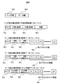
- FIG. 8 shows the configuration of a data string that is sent from the common processing CPU core 250 to the first data filter 551 and the second data filter 552.
- the data string is composed of a header part 910 and a data part 950, and each of the header part 910 and the data part 950 has one or more components.
- the header section 910 stores information to be referred to when the first data filter 551 and the second data filter 552 select a data string, and the data section 950 stores other data.
- the constituent elements of the header section 910 include representative space coordinates, and the constituent elements of the data section 950 include image data, distance data, and edge strength data.
- Both the header unit 910 component and the data unit 950 component have type 901 at the head.
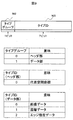
- the type 901 has the configuration shown in FIG. 9, and a type group (902) for identifying the header portion 910 or the data portion 950 and one type ID (903) indicating which component of the header portion 910 or the data portion 950 is included. It consists of 7 bits.
- the first data filter 551 and the second data filter 552 can easily detect the appearance of the header portion 910 and can easily detect the head of the data string.
- the components (representative space coordinates) of the header part have a representative X coordinate 991, a representative Y coordinate 992, and a distance 993 corresponding to the object existence estimation area after type 901.
- a distance 993 is a distance to the object presence estimation region.
- the component of the data part has the horizontal size (image horizontal size 961) and vertical size (image vertical size 962) of the image corresponding to the object presence estimation area after type 901, and then the image from the top in order.
- the value 965 of each pixel is obtained by repeating a data string in which the value of each pixel is arranged in order of the horizontal size from the left pixel for the vertical size.
- the component of the data part has the horizontal size (distance horizontal size 971) and vertical size (distance vertical size 972) of the distance data information corresponding to the object presence estimation area after type 901, and then the top of the image A value 975 of each pixel obtained by repeating a data string in which the distance of each pixel from the left pixel is arranged in order of the horizontal size is followed by the vertical size.
- the component of the data part has the horizontal size (edge strength horizontal size 981) and vertical size (edge strength vertical size 982) of the edge strength data information corresponding to the object presence estimation area after type 901, and then Then, the edge strength 985 of each pixel is repeated by repeating a data sequence in which the edge strength of each pixel is arranged in order of the horizontal size from the left pixel in order from the top of the image.
- Each edge strength is a set of a horizontal edge strength and a vertical edge strength.
- each information Corresponding size By having the size of each pixel value 965, the distance 975 of each pixel, and the edge strength 985 of each pixel, the resolution of the sensor 100 and the processing capability of the common processing CPU core 250, the resolution of each information Corresponding size can be specified.
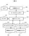
- the configuration of FIG. 10 is a configuration using a cache memory instead of the local memory of FIG.
- the first object detection CPU core 601 has a first local cache memory 511
- the second object detection CPU core 602 has a second local cache memory 512
- the common processing CPU core 250 has a third local cache memory 510.
- the first local cache memory 511, the second local cache memory 512, and the third local cache memory 510 are also connected to a common cache memory 520 that operates as a secondary cache memory.
- a main memory 525 is connected to the end of the common cache memory 250.
- the sensor 100, the first object detection CPU core 601 and the second object detection CPU core 602 perform the same processing as in the configuration of FIG.
- the common processing CPU core 250 writes information necessary for the object detection processing in the first local memory 501 or the second local memory 502 based on the result of the assignment determination processing 310 in FIG. In this configuration, writing is performed to the address area to be written to the third local cache memory 510. At this time, information is exchanged by using different address space areas for the object existence estimation area processed by the first object detection CPU core 601 and the object existence estimation area processed by the second object detection CPU core 602. The processing is assigned to the first object detection CPU core 601 and the second object detection CPU core 602.
- the first object detection CPU core 601 and the second object detection CPU core 602 use the first object as the address space area used for passing information of the object presence estimation area to be processed.
- the address space area to be processed only by the detection CPU core 601 and the address space area to be processed only by the second object detection CPU core 602 may be separated. Particularly when both the first object detection CPU core 601 and the second object detection CPU core 602 have a large number of object presence estimation areas to be processed, the address space area is assigned in this way, Information relating to the object presence estimation area to be processed by both the object detection CPU core 601 and the second object detection CPU core 602 may be written in one address space area instead of two places.
- the data to be written to the third local cache memory 510 cannot be stored, the cache hit rate is reduced, and the number of times the common processing CPU core 250 writes information to the third local cache memory 510 can be suppressed. Become advantageous.
- the common processing CPU core 250 can directly write to the first local cache memory 511 and the second local cache memory 512, that is, the object detection CPU core corresponding to each local cache memory accesses. In this case, it may have a function of writing to the local cache memory so that a cache hit state occurs. In the case of having this function, the information transferred to the first object detection CPU core 601 is directly transferred to the first local cache memory 511, and the information transferred to the second object detection CPU core 602 is directly transferred to the second local cache memory 512. Write to.
- the common processing CPU core 250 has a function of simultaneously writing directly to the first local cache memory 511 and the second local cache memory 512
- the first object detection CPU core 601 and the second object detection CPU core 602 are used. Information to be processed in both cases can be written to the first local cache memory 511 and the second local cache memory 512 at the same time, thereby suppressing the number of times the common processing CPU core 250 writes the memory.
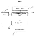
- FIG. 11 omits the second local memory 502 and the second object detection CPU core 602 for the second object detection processing 582 of FIG. Therefore, the common processing and object detection processing CPU core 255 is replaced.
- the second local memory 502 and the second object detection CPU core 602 can be omitted. There is.
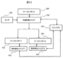
- the common processing CPU core 250, the first object detection CPU core 601, and the second object detection CPU core 602 is connected to the main memory 525, and part of information transferred from the common processing CPU core 250 to the first object detection CPU core 601 and the second object detection CPU core 602 is performed via the main memory 525.
- Information that is passed through the main memory 525 is information that is rarely repeatedly referred to by the first object detection CPU core 601 and the second object detection CPU core 602, so that memory access by not using a local memory It is possible to suppress performance degradation due to bandwidth limitation.
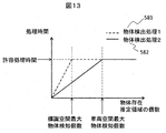
- FIG. 13 shows a schematic relationship between the number of object presence estimation regions targeted by the first object detection process 581 and the second object detection process 582 and the processing time of each process.
- the first object detection process 581 and the second object detection process 582 operate using a CPU core and a local memory that operate in parallel, respectively, as the number of object presence estimation regions targeted by each process increases. Independently increases processing time. However, in the object detection process targeting the sign space 820 and the object detection process targeting the vehicle space 810, the processing time spent per object existence estimation region is usually different, and therefore the slope of the graph is different. Further, in order to use the object detection processing result in real-time application such as automobile control, the processing must be stopped within the allowable processing time. In other words, the first object detection process 581 terminates the process with the maximum number of detected objects in the sign space, and the second object detection process 582 terminates the process with the maximum number of detected objects in the vehicle space.
- a configuration is also conceivable in which the first object detection process 581 and the second object detection process 582 can identify and detect both the object in the sign space 820 and the object in the vehicle space 810.
- an object detection process is performed on a certain object existence estimation area in either the first object detection process 581 or the second object detection process 582, an object existing in the object existence estimation area is detected. It is possible to detect either an object in the sign space 820 or an object in the vehicle space 810. That is, since it is not necessary to provide a region where the sign space 820 and the vehicle space 810 overlap, the first object detection CPU core 601 and the second object detection CPU core 602 avoid processing the same object, The utilization efficiency of the detection CPU core can be improved.
- FIG. 14 shows that the processing time for the object presence estimation area of the sign space 820 that the first object detection processing 581 should originally process exceeds the allowable processing time, and the second processing object detection processing 582 of the vehicle space 810 that should be originally processed.
- a schematic relationship between the number of object presence estimation regions and the processing time when there is a margin in processing time for the object presence estimation region is shown. As this relationship indicates, as soon as the object detection process for the object existence estimation region in the vehicle space 810 to be originally processed by the second object detection processing 582 is completed, the object existence estimation region in the sign space 820 is within the allowable processing time range.
- Object detection processing can be performed.
- the slope of the graph of the second object detection processing 582 changes. That is, it is possible to increase the maximum number of objects that can be processed in the object existence estimation region of the sign space 820.
- the common processing CPU core 250, the first object detection CPU core 601, and the second object detection CPU core 602 may be included in individual components, or may be configured such that all CPU cores are mounted on an integrated circuit. Also, a combination of both may be used.
- the object detection processing unit which is a unit in which local memory or cache memory is combined with the object detection core, may have three or more configurations.
- a space other than the sign space 820 and the vehicle space 810 may be additionally defined so that the object detection processing assignment destination corresponds to the number of object detection processing units.
- a part of the object processing unit may be adapted to both the object in the sign space 820 and the object in the vehicle space 810. Allocation of the object detection processing unit is actually determined according to the processing load on the object in the sign space 820 and the processing load on the object in the vehicle space 810.
- a function of dynamically changing the ranges of the sign space 820 and the vehicle space 810 is added to the configuration shown in the first embodiment, depending on the gradient condition ahead.
- FIG. 15 shows a situation where there is an uphill ahead, or a situation where the uphill slope ahead becomes steep.
- the upper end of the vehicle space 810 is moved upward, and the detection object in the vehicle space 810 such as a vehicle located higher than the host vehicle is outside the vehicle space 810, and a situation where detection is impossible can be prevented.
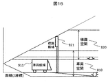
- FIG. 16 shows a situation where there is a downhill ahead, or a situation where the forward slope is steep.
- the lower end of the sign space 810 is moved downward, and the detection target object in the sign space 820 such as a sign or a signal is outside the sign space 820, and a situation where detection is impossible can be prevented.
- the assignment control parameter 400 can be corrected from the first object detection processing 581 and the second object detection processing 582 in the processing flow shown in FIG. To do.
- the road surface is detected from the result of road surface detection or white line detection in the second object detection processing 582.
- the distance that cannot be obtained is obtained, and the lower end of the sign space 810 is determined on the assumption that there is a descending gradient with the maximum slope according to the road standard from the position to the farthest object detection range determined in advance as a specification.
- the range of the sign space 820 and the vehicle space 810 By dynamically changing the range of the sign space 820 and the vehicle space 810, it is not necessary to determine the space area belonging to both the sign space 820 and the vehicle space 810 in consideration of the influence of the change in the road gradient.
- the area belonging to both the vehicle space 810 and the vehicle space 810 can be reduced, so that the number of object existence estimation areas to be processed in both the first object detection process 581 and the second object detection process 582 can be suppressed, and the processing efficiency of the object detection process Will improve.
- the assignment determination process 310 is performed using the results of the edge parameter distribution 370, the aspect ratio calculation 350, and the normalized size calculation 360, and the first object detection process Object detection processing is assigned to one or both of 581 and second object detection processing 582.
- Information is transferred to the first object detection process 581 and the second object detection process 582 in the same manner as the method described in the first embodiment.
- the configuration using the data filter shown in FIG. 7 is used, the format of the component of the header portion 910 of the data string is added as will be described later.
- the common processing CPU core 250 also performs processing of edge tendency parameter calculation 370, aspect ratio calculation 350, and normalized size calculation 360.
- the assignment determination processing 310 it is determined whether the object detection processing for the object presence estimation region is assigned to the first object detection processing 581 to the second object detection processing 582 by the representative space coordinates as in the first embodiment. However, in the case where it is necessary to assign to both the first object detection processing 581 and the second object detection processing 582, using the results of the edge tendency parameter calculation 370, the aspect ratio calculation 350, and the normalized size calculation 360, It is determined whether it is sufficient to assign to either one, and in such a case, processing is assigned only to the object detection processing.
- the edge tendency parameter calculation 370 is performed using the output of the image / distance information association processing 260.
- the edge detection process is calculated and calculated based on the difference tendency with the neighboring pixels of the image 150. However, since the object presence estimation region to be processed is extracted based on the distance information 155, the image and distance information association process 260 is performed.
- the edge tendency parameter is calculated using the corresponding part image.
- the edge analysis is performed in detail in the first object detection process 581 and the second object detection process 582, and is used when final determination of the presence / absence of an object and specification of the type is performed.
- the image is scanned roughly every 16 lines in the vertical and horizontal directions, and the edge tendency of the image is acquired with a reduced processing load. More specifically, the horizontal edge strength and the vertical edge strength are obtained by obtaining the average of the edge strengths that tend to be orthogonal to the line on the scan target line.
- the aspect ratio calculation 350 and the normalized size calculation 360 are performed using the output of the association process 260.
- the image 150 is not used, but is calculated using the smallest rectangle surrounding the object existence estimation region used for calculating the representative space coordinates. That is, the aspect ratio of the rectangle is set as the result of the aspect ratio calculation 350, and the size obtained by normalizing the rectangle with the object existing at the same distance (for example, 10 m ahead) is set as the normalized size calculation 360 result.
- the format of the constituent element of the header of the data string shown in FIG. 18 is added to the first embodiment, and the edge tendency, the aspect ratio, the normality of the object existence estimation region are added by the data filter. After confirming the data size, it is possible to determine whether or not to write data to the local memory in the subsequent stage.
- the components (edge tendency parameters) of the header portion 910 are type 901, edge horizontal strength 935 indicating horizontal edge strength, edge vertical strength 936 indicating vertical edge strength, and edge.
- edge horizontal vertical intensity ratio 937 indicating the ratio of horizontal intensity to vertical intensity.
- the component (aspect ratio) of the header portion 910 has an aspect ratio 931 that is a value obtained by dividing the vertical length of the smallest rectangle surrounding the object presence estimation area by the horizontal length after type 901.
- Normalized size that is a component of the header part 910 is a normalized size X941 that is a value obtained by normalizing the horizontal length of the smallest rectangle surrounding the object existence estimation area after the type 901, and It has a normalized size Y942 that is a value obtained by normalizing the length in the vertical direction.
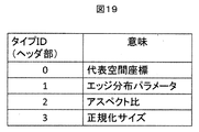
- the type ID 903 of the header part 910 shown in FIG. 9 in the first embodiment is assigned as shown in FIG.
- the assignment of the type group 902 and the type ID 903 is the same as in the first embodiment.
- the object detection processing unit which is a unit in which local memory or cache memory is combined with the object detection core, may have three or more configurations. In this case, in addition to the combinations shown in the first embodiment, either or both of the vehicle space 810 and the sign space 820 are described in detail using the results of the edge parameter calculation 370, the aspect ratio calculation 350, and the normalized size calculation 360.
- the object detection processing unit may be assigned by grouping. For example, regarding an object detected by the vehicle space 810, there is a method in which a certain object detection processing unit targets a person and a vehicle, and another object detection processing unit targets another object.
- the dynamic change function of the sign space 820 and the vehicle space 810 shown in the second embodiment may be combined with this embodiment.
- Marker candidate 931 ... Aspect ratio, 935 ... Edge horizontal intensity, 936 ... Edge vertical intensity, 937 ... Edge horizontal vertical intensity ratio , 941 ... Normalized size X, 942 ... Normalized size Y, 950 ... Data part, 961 ... Image horizontal size, 962 ... Image vertical size, 965 ... Value of each pixel, 971 ... Distance horizontal size, 972 ... Distance vertical size , 975 ... each pic Distance Le, 981 ... edge strength horizontal size, 982 ... edge strength vertical size, 985 ... edge strength of each pixel, 991 ... representative X-coordinate, 992 ... Representative Y coordinate, 993 ... distance
Landscapes
- Physics & Mathematics (AREA)
- General Physics & Mathematics (AREA)
- Engineering & Computer Science (AREA)
- Computer Vision & Pattern Recognition (AREA)
- Theoretical Computer Science (AREA)
- Traffic Control Systems (AREA)
- Image Analysis (AREA)
Abstract
本発明は、複数の処理装置を備える車載画像処理装置において、各処理装置が物体の識別処理のために記憶装置にアクセスする際のボトルネックを抑制し、処理を高速化することができる車載画像処理装置を提供することを目的とする。 本発明は、撮像部から取得した画像を構成する画像要素に対して距離情報を付与し、該距離情報を用いて複数の処理領域を設定する第1の処理部と、識別対象とする処理領域が前記距離情報を用いてそれぞれ割り当てられ、割り当てられた処理領域に対して前記物体の識別処理を行う複数の処理装置を有する第2の処理部と、を備える。
Description
本発明は、車載画像処理装置に関する。
車載画像処理装置として特許文献1に示された装置がある。特許文献1では車載用マルチアプリ実行装置が示されており、歩行者や車両を物体として検知する機能について述べられている。また、複数の処理装置を有するいわゆるマルチCPUの構成や動作についても述べられている。
また、特許文献1では、物体を認識する認識アプリケーションごとにCPUを割り当てることが提案されている。
ところで、このように処理装置を複数設けたとしても、複数の処理装置が識別処理を行うために行われる記憶装置へのアクセスを適切に制御しなければ、記憶装置へのアクセスがボトルネックとなり、結果として処理を高速化することができない。
そこで、本発明は、複数の処理装置を備える車載画像処理装置において、各処理装置が物体の識別処理のために記憶装置にアクセスする際のボトルネックを抑制し、処理を高速化することができる車載画像処理装置を提供することを目的とする。
本発明は、撮像部から取得した画像を構成する画像要素に対して距離情報を付与し、該距離情報を用いて複数の処理領域を設定する第1の処理部と、識別対象とする処理領域が前記距離情報を用いてそれぞれ割り当てられ、割り当てられた処理領域に対して前記物体の識別処理を行う複数の処理装置を有する第2の処理部と、を備える。
或いは、本発明は、撮像部から取得した画像に対して複数の処理領域を設定する第1の処理部と、前記複数の処理領域のうちそれぞれ異なる処理領域を記憶する複数の記憶装置と、前記複数の記憶装置にそれぞれアクセスして前記各記憶装置に格納された処理領域に対する画像処理を行う複数の処理装置を有する第2の処理部と、を備える。
本発明によれば、複数の処理装置を備える車載画像処理装置において、各処理装置が物体の識別処理のために記憶装置にアクセスする際のボトルネックを抑制し、処理を高速化することができる。
以下、本発明の実施形態を図面に基づいて説明する。
装置の基本構成を図1に示す。センサ100は外界の画像を取得するカメラ、及び画像に対応する距離情報155を取得する機器、さらに必要に応じて勾配センサや加速度センサ、GPS装置により構成される。距離情報155を取得する機器は任意であり、例えばレーザレーダやミリ波レーダを用いることができる。また、カメラをステレオカメラ構成として視差情報から距離を取得する手法を用いることもできる。
センサ100で取得したデータは距離情報取得処理部200により、実際の距離情報155を求め、またカメラから取得した画像との対応付けを行う。距離情報取得処理部200では、その後の物体検出処理で共通的に利用する付加データの算出も(例えば、エッジ画像など)を行う。
割当て制御パラメータ400は距離情報取得処理部200で算出したデータを元に物体検出CPUコアを割当てる際の条件である。この条件は固定でも良い。しかし、例えば勾配センサからの情報を元に動的に変更することも考えられる。
CPUコア割当て処理部300は、割当て制御パラメータ400を元に距離情報取得部200から来る各種データを、最終的に物体検出処理を行う第1の物体検出CPUコア601あるいは第2の物体検出CPUコア602がアクセスできるメモリに格納する。また、第1の物体検出CPUコア601がアクセスできるメモリと第2の物体検出CPUコア602がアクセスできるメモリの両方に格納することもある。
第1のローカルメモリ501は第1の物体検出CPUコア601がCPUコア割当て処理部300から必要なデータを受け取り、また第1の物体検出CPUコア601が演算処理を行う際に用いる記憶装置である。第2のローカルメモリ502は第2の物体検出CPUコア602がCPUコア割当て処理部300から必要なデータを受け取り、また第2の物体検出CPUコア602が演算処理を行う際に用いる記憶装置である。
第1の物体検出CPUコア601及び第2の物体検出CPUコア602はCPUコア割当て処理部(300)により割当てられた画像要素に関して演算処理を行い、最終的に空間上のどの位置にどのような物体が存在するか検出を行うCPUコアである。物体検出結果は車両向けネットワーク(CAN)インタフェース等の入出力インタフェースを介して外部へ出力する。
物体検出処理性能の向上、具体的には対象とする物体の種類の拡大や物体の同時検出個数の向上など、を図る場合は、ローカルメモリと物体検出CPUコアを組として追加する。それぞれの物体検出CPUコアに対し密に結合されるローカルメモリを用意することで、物体検出処理に必要な演算性能の向上と並行し、演算処理に必要なメモリアクセス帯域も向上させることができ、メモリアクセス帯域不足に伴うボトルネックを防止できる。演算性能とメモリアクセス帯域を同時に向上できるため、装置の性能及び機能スケーラビリティが向上する。
図2及び図3を用い、道路及びその周辺の物体を検出する際における、CPUコア割当て処理部300が物体検出CPUコアを割当てる方法を説明する。図2は車両のフロントガラス中央上部から見た画像、すなわち物体検出装置のカメラで取得できる画像、図3は図2の画像に対応する空間を道路の横側から見た断面図である。
物体検出CPUコアを割当てるために、図2及び図3に示すように、センサ100で監視可能な空間を標識空間820と車両空間810に分割する。標識空間820は空間上部に存在する物体を対象とした空間、車両空間810は空間下部に存在する物体を対象とした空間である。便宜的に標識空間820と車両空間810と記すが、それぞれの空間領域に存在する物体の検出と識別を対象とする空間である。例えば、車両空間810は人物など空間下部に存在する物体の検出と識別も対象とする。
図2及び図3に示すように、標識空間820と車両空間810を一部重ねることで、標識空間820が対象とする物体と車両空間810が対象とする物体が共に存在し得る空間に対応する。
図3に示すように、標識空間820及び車両空間810それぞれの領域に対応する上下画角は距離(Z座標)により異なる。たとえば、センサから遠方では、領域の境界線の高さは一定となり、遠方になるほど上下画角が狭くなる。すなわち、図2に存在する範囲であっても、検出対象外となる領域が存在する。
物体の存在を空間上の位置ととらえ、物体検出範囲を限定することで、物体が存在すると推定できる領域(以降、物体存在推定領域)をCPUコア割当て処理部300で絞り込むことができ、物体検出処理を行うCPUコアを効率よく利用することが出来る。
尚、図3では上下方向の領域を示しているが、左右方向に関しても遠方に関しては同様に物体検出範囲を限定する。
標識空間820及び車両空間810の範囲は、それぞれ予め空間座標の範囲として定義し、割当て制御パラメータ400として用意する。空間座標の範囲はセンサの中心座標を基準にして、図2のX座標方向(左右方向)及びY座標方向(上下方向)について、上、下、左、右方向の実空間における長さで定義する。但し、遠方については長さを短くするなど、より多くの座標、あるいは長さ情報を用いて空間座標の範囲を定義しても構わない。
本発明の物体検出装置の処理フローを図4に示す。センサ100より入力される画像150及び距離情報155は、まず画像と距離情報の対応付け処理260を行い、物体存在推定領域とその部分の距離情報155の対応付け処理を行う。物体存在推定領域は、距離情報155を用いて隣接部分と距離の差が少ない部分をひと固まりの領域として検出する。
画像150と距離情報155の対応付け処理260は画像150と距離情報155の座標関係に関するマッピング情報を予め作成しておき、このマッピング情報を用いて行う。この際、画像150取得用のセンサと距離情報155取得用のセンサの設置位置のずれにより、対象とする物体存在推定領域に対応する距離に依存して画像150と距離情報155の座標関係にずれが生じると考えられるので、距離情報155に含まれる当該物体存在推定領域までの距離を用いて画像150とのマッピングに補正を加え、当該物体存在推定領域に対応する画像150上の領域を決定する。
距離情報の取得にステレオカメラを用いる場合は、画像とその画像に対する視差情報が得られるため、自ずと画像150に対応する距離情報155を得られる。
図4に示す画像150と距離情報155では、画像と距離情報の対応付け処理260により、距離情報155の物体存在推定領域A(271)が画像150の車両171、物体存在推定領域B(261)が画像150の信号機161、物体存在推定領域C(281)が画像150の標識181、物体存在推定領域D(291)が画像150の人物191に対応付けられる。
画像と距離情報の対応付け処理260の後、代表空間座標算出320で各物体存在推定領域に対する代表空間座標を算出する。
代表空間座標の算出方法について図5を用いて説明する。図5に示すように物体存在推定領域を囲む最小の長方形を求め、その中心座標と距離情報を用いて代表空間座標を算出する。例えば、物体存在推定領域C(281)の代表空間座標は物体存在推定領域C(281)を囲む最小の長方形Rc(182)の中心座標及び物体存在推定領域C(281)の距離(20m)より算出し、物体存在推定領域D(291)の代表空間座標は物体存在推定領域D(291)を囲む最小の長方形Rd(292)の中心座標及び物体存在推定領域D(291)の距離(24m)より算出する。
割当て判定処理310では、代表空間座標算出処理320で求めた物体存在推定領域毎に割当て制御パラメータ400を用い、物体検出処理を行う第1の物体検出処理581、第2の物体検出処理582の割当てを行い、当該物体存在推定領域に対応する画像150の領域、距離250の領域、及び割り当て判定処理310までの処理で算出した情報(代表空間座標や物体存在推定領域を囲む長方形のサイズ等)を割当て先に送り出す。
割当て判定処理310では、代表空間座標算出処理320で求めた物体存在推定領域毎に割当て制御パラメータ400を用い、物体検出処理を行う第1の物体検出処理581、第2の物体検出処理582の割当てを行い、当該物体存在推定領域に対応する画像150の領域、距離250の領域、及び割り当て判定処理310までの処理で算出した情報(代表空間座標や物体存在推定領域を囲む長方形のサイズ等)を割当て先に送り出す。
尚、物体存在推定領域毎に画像150や距離情報155から対応する領域を切り出す代わりに、割当て制御パラメータ400に対応して各物体検出処理部が必要とする領域を一括してそれぞれの物体検出処理部へ送り、さらに個々の物体存在推定領域の領域を特定する情報(代表空間座標や物体存在推定領域を囲む長方形の座標)を送る方法も考えられる。
割り当て判定処理310により、標識空間820に属する物体存在推定領域を第1の物体検出処理581に、車両空間810に属する物体存在推定領域を第2の物体検出処理582に割当てることが可能である。
第1の物体検出処理581は標識空間820に存在し得る物体の種類について、物体存在推定領域毎にその画像の特徴、例えば画像のエッジの分布や輝度及び色の分布、領域のアスペクト比、パターンへのマッチング率など詳細に解析し、当該物体推定領域に本当に物体が存在するのか、存在する場合はその物体の種類(信号機や標識など)は何か、さらに必要であれば物体の示すより詳細な情報の抽出(信号機であればその点灯状態、速度標識であれば制限速度など)を行う。
第2の物体検出処理582は車両空間810に存在し得る物体の種類について、第1の物体検出処理581と同様に詳細に解析を行い、当該物体推定領域に本当に物体が存在するのか、存在する場合はその物体の種類(自動車、二輪車、自転車、歩行者、白線、路面上の標識や路面の凹凸など)は何か、さらに必要であれば物体の示すより詳細な情報の抽出(自動車であればストップランプやウインカーの表示状態、歩行者であれば向きや表情など)を行う。
第1の物体検出処理581及び第2の物体検出処理582の物体検出結果は、ネットワークインタフェースなどを介して、車両制御コンピュータへ伝えることで、安全支援、運転支援さらには自動運転に活用できる。
図6、図7、図10から図12に本発明を実現するハードウェアの構成例を示す。まず図6の構成について説明する。センサ100は外界の画像を取得するカメラ、及び画像に対応する距離情報を取得する機器、さらに必要に応じて勾配センサや加速度センサ、GPS装置により構成される。共通処理CPUコア250はセンサ100から入力した信号を、装置内部で処理をする上で適した形式への変換をした上で、画像と距離情報の対応付け処理260、代表空間座標算出処理320、及び割当て判定処理310を行う。そして割当て判定処理310の結果に基づき、物体検出処理に必要となる情報を第1のローカルメモリ501または第2のローカルメモリ502の一方、あるいは両方に書き込む。
割当て制御パラメータ400は共通処理CPUコア250のプログラムの一部として実装する。
共通処理CPUコア250からは第1のローカルメモリ501及び第2のローカルメモリ502の両方へ同時に書き込みする機能を有する。本機能により、標識空間820及び車両空間810に両方に属する物体存在推定領域に関する情報を1回の操作で行うことができ、共通処理CPUコア250のメモリ書き込み処理に伴うオーバヘッド、及び共通処理CPUコア250と第1のローカルメモリ501及び第2のローカルメモリ502を接続するバスの利用帯域を抑制することができる。
第1のローカルメモリ501は共通処理CPUコア250から第1の物体検出CPUコア601への情報の受け渡し、及び第1の物体検出CPUコア601の処理に用いる記憶装置であり、第2のローカルメモリ502は共通処理CPUコア250から第2の物体検出CPUコア602への情報の受け渡し、及び第2の物体検出CPUコア602の処理に用いる記憶装置である。
物体検出CPUコアと当該CPUコアに対応するローカルメモリの組で物体検出処理を行う。すなわち、第1のローカルメモリ501と第1の物体検出CPUコア601により第1の物体検出処理581を行い、第2のローカルメモリ502と第2の物体検出CPUコア602により第2の物体検出処理582を行う。
尚、共通処理CPUコア250、第1の物体検出CPUコア601、及び第2の物体検出CPUコア602は処理速度向上の為、それぞれ専用処理回路に置き換えても良いし、専用処理回路を付加して処理内容の一部を高速化しても良い。
図7の構成は図6に対して第1のデータフィルタ551及び第2のデータフィルタ552を追加した構成となっている。この構成では、共通処理CPUコア250では割当て判定処理310の直前まで処理を行い、図6の構成で共通処理CPUコア250より第1のローカルメモリ501や第2のローカルメモリ502に書き込みを行っていたデータはデータ列の形態にして第1のデータフィルタ551及び第2のデータフィルタ552へ同時に流す。
第1のデータフィルタ551は流れてきたデータ列から標識空間820に存在し得る物体にかかわるデータのみを抽出し、第1のローカルメモリ501へ書き込む。
第2のデータフィルタ552は流れてきたデータ列から車両空間810に存在し得る物体にかかわるデータのみを抽出し、第2のローカルメモリ502へ書き込む。
第1のデータフィルタ551及び第2のデータフィルタ552がそれぞれデータ列を選択する基準はそれぞれのフィルタを開発する時点で固定しても良いし、共通処理CPUコア250より適宜設定する構成にしても良い。
第1のローカルメモリ501、第2のローカルメモリ502、第1の物体検出CPUコア601、及び第2の物体検出CPUコア602は図6の構成と同様に動作する。
図7の構成では第1のデータフィルタ551及び第2のデータフィルタ552が追加されるため、図6に対し装置の実装規模は大きくなるが、共通処理CPUコア250の処理負荷を低減でき、共通処理CPUコア250の処理では処理負荷が高すぎる複雑な条件であっても、第1の物体検出CPUコア601と第2の物体検出CPUコア602へ処理を割当てることが可能となる。
図8に共通処理CPUコア250より第1のデータフィルタ551及び第2のデータフィルタ552へ流すデータ列の構成を示す。
データ列はヘッダ部910とデータ部950で構成し、ヘッダ部910及びデータ部950はそれぞれ1個以上の構成要素を持つ。ヘッダ部910には第1のデータフィルタ551及び第2のデータフィルタ552がデータ列を選択する際に参照する情報を格納し、データ部950にはそれ以外のデータを格納する。ヘッダ部910に選択に必要となる情報を固めることで、データ部950がデータフィルタに来る前に書き込み先のローカルメモリにデータを書き込む必要があるか否か判断可能となり、第1のデータフィルタ551及び第2のデータフィルタ552が判断完了までデータ部950を一時保存することが不要となる。
ヘッダ部910の構成要素には代表空間座標、データ部950の構成要素には画像データ、距離データ、エッジ強度データが存在する。ヘッダ部910構成要素及びデータ部950構成要素は、共に先頭にタイプ901を持つ。タイプ901は図9に示す構成であり、ヘッダ部910かデータ部950を識別するタイプグループ(902)1ビットとヘッダ部910あるいはデータ部950のどの構成要素であるかを示すタイプID(903)7ビットで構成される。
タイプグループ902を最初に1ビット持つことで、第1のデータフィルタ551及び第2のデータフィルタ552はヘッダ部910の出現を容易に検出でき、データ列の先頭を容易に検出可能となる。
ヘッダ部の構成要素(代表空間座標)はタイプ901の後に物体存在推定領域に対応する代表X座標991、代表Y座標992及び距離993を持つ。距離993は物体存在推定領域まで距離である。
データ部の構成要素(画像データ)はタイプ901の後に物体存在推定領域に対応する画の水平サイズ(画像水平サイズ961)及び垂直サイズ(画像垂直サイズ962)を持ち、その後に画像の上から順に垂直サイズ分、左側のピクセルから各ピクセルの値を水平サイズ分順に並べたデータ列を繰り返した各ピクセルの値965が続く。
データ部の構成要素(距離データ)はタイプ901の後に物体存在推定領域に対応する距離データ情報の水平サイズ(距離水平サイズ971)及び垂直サイズ(距離垂直サイズ972)を持ち、その後に画像の上から順に垂直サイズ分、左側のピクセルから各ピクセルの距離を水平サイズ分順に並べたデータ列を繰り返した各ピクセルの値975が続く。
データ部の構成要素(エッジ強度データ)はタイプ901の後に物体存在推定領域に対応するエッジ強度データ情報の水平サイズ(エッジ強度水平サイズ981)及び垂直サイズ(エッジ強度垂直サイズ982)を持ち、その後に画像の上から順に垂直サイズ分、左側のピクセルから各ピクセルのエッジ強度を水平サイズ分順に並べたデータ列を繰り返した各ピクセルのエッジ強度985が続く。各エッジ強度は水平方向のエッジ強度と垂直方向のエッジ強度の組である。
各ピクセルの値965、各ピクセルの距離975及び各ピクセルのエッジ強度985でそれぞれサイズを持つことで、センサ100の分解能や共通処理CPUコア250の演算能力の都合に合わせ、それぞれの情報の分解能に対応したサイズを指定可能となる。
図10の構成は、図6のローカルメモリの代わりにキャッシュメモリを用いた構成である。第1の物体検出CPUコア601には第1のローカルキャッシュメモリ511、第2の物体検出CPUコア602には第2のローカルキャッシュメモリ512、共通処理CPUコア250には第3のローカルキャッシュメモリ510が接続されており、それぞれのCPUコアの1次キャッシュメモリとして動作する。第1のローカルキャッシュメモリ511、第2のローカルキャッシュメモリ512、及び第3のローカルキャッシュメモリ510は2次キャッシュメモリとして動作する共通キャッシュメモリ520にも接続されている。共通キャッシュメモリ250の先にはメインメモリ525が接続されている。
図10の構成でもセンサ100、第1の物体検出CPUコア601及び第2の物体検出CPUコア602は図6の構成と同様の処理を行う。共通処理CPUコア250は割当て判定処理310の結果に基づき、図6の構成では物体検出処理に必要となる情報を第1のローカルメモリ501または第2のローカルメモリ502に書き込みを行うが、図10の構成では第3のローカルキャッシュメモリ510への書き込み対象となるアドレス領域に書き込みを行う。この際、第1の物体検出CPUコア601で処理する物体存在推定領域と第2の物体検出CPUコア602で処理する物体存在推定領域でそれぞれ異なるアドレス空間領域を用いて情報の受け渡しを行うことで、第1の物体検出CPUコア601と第2の物体検出CPUコア602へ処理の割当てを行う。
図10の構成においては、第1の物体検出CPUコア601と第2の物体検出CPUコア602の両方で処理対象とする物体存在推定領域の情報の受け渡しに用いるアドレス空間領域を、第1の物体検出CPUコア601のみで処理対象とするアドレス空間領域、及び第2の物体検出CPUコア602のみで処理対象とするアドレス空間領域と分けても良い。特に第1の物体検出CPUコア601と第2の物体検出CPUコア602の両方で処理対象とする物体存在推定領域の個数が多い場合は、このようにアドレス空間領域を割当てることで、第1の物体検出CPUコア601と第2の物体検出CPUコア602の両方で処理対象とする物体存在推定領域に関する情報を2箇所ではなく1箇所のアドレス空間領域に書き込めば良い。第3のローカルキャッシュメモリ510に書き込むデータが収まらなくなり、キャッシュヒット率が低下する状況や、共通処理CPUコア250が第3のローカルキャッシュメモリ510に情報の書き込みを行う回数を抑制でき、処理性能上有利になる。
図10に示す構成では、共通処理CPUコア250が直接第1のローカルキャッシュメモリ511や第2のローカルキャッシュメモリ512へ書き込みを行える機能、すなわちそれぞれのローカルキャッシュメモリに対応する物体検出CPUコアがアクセスした際に、キャッシュヒットする状態となるようローカルキャッシュメモリに書き込む機能を有しても良い。この機能を有する場合、第1の物体検出CPUコア601に受け渡す情報は直接第1のロ
ーカルキャッシュメモリ511へ、第2の物体検出CPUコア602に受け渡す情報は直接第2のローカルキャッシュメモリ512へ書き込みを行う。さらに共通処理CPUコア250が直接第1のローカルキャッシュメモリ511や第2のローカルキャッシュメモリ512に同時に書き込む機能を有する場合には、第1の物体検出CPUコア601と第2の物体検出CPUコア602の両方で処理対象とする情報は、第1のローカルキャッシュメモリ511や第2のローカルキャッシュメモリ512に同時に書き込むことで、共通処理CPUコア250のメモリ書き込み回数を抑制できる。
ーカルキャッシュメモリ511へ、第2の物体検出CPUコア602に受け渡す情報は直接第2のローカルキャッシュメモリ512へ書き込みを行う。さらに共通処理CPUコア250が直接第1のローカルキャッシュメモリ511や第2のローカルキャッシュメモリ512に同時に書き込む機能を有する場合には、第1の物体検出CPUコア601と第2の物体検出CPUコア602の両方で処理対象とする情報は、第1のローカルキャッシュメモリ511や第2のローカルキャッシュメモリ512に同時に書き込むことで、共通処理CPUコア250のメモリ書き込み回数を抑制できる。
図11の構成は、図6の第2の物体検出処理582向けの第2のローカルメモリ502及び第2の物体検出CPUコア602を省略し、共通処理CPUコア250に第2の物体検出処理582も含め処理させるために、共通処理兼物体検出処理CPUコア255に置き換えた構成である。この構成では図6の構成において共通処理CPUコア250で行う処理及び第2の物体検出CPUコア602の負荷が軽い場合、第2のローカルメモリ502及び第2の物体検出CPUコア602が省略できる利点がある。
図12の構成は、図6の構成にメインメモリ525を追加した構成である。第1のローカルメモリ501、第2のローカルメモリ502、第3のローカルメモリ290の容量を抑制するために、共通処理CPUコア250、第1の物体検出CPUコア601、第2の物体検出CPUコア602をメインメモリ525に接続し、共通処理CPUコア250から第1の物体検出CPUコア601や第2の物体検出CPUコア602に受け渡す情報の一部について、メインメモリ525を介して行う。メインメモリ525を介して受け渡す情報は第1の物体検出CPUコア601及び第2の物体検出CPUコア602で繰り返し参照されることが少ない情報とすることで、ローカルメモリを用いないことによるメモリアクセス帯域の制限に伴う性能低下を抑制することが出来る。
図13に第1の物体検出処理581及び第2の物体検出処理582がそれぞれ対象とする物体存在推定領域の個数と、それぞれの処理の処理時間の概略関係を示す。
第1の物体検出処理581及び第2の物体検出処理582はそれぞれ並列に動作するCPUコア及びローカルメモリを用いて動作するため、それぞれの処理が対象とする物体存在推定領域の個数が増加するに従い、独立して処理時間が増加する。但し、標識空間820を対象とする物体検出処理と車両空間810を対象とする物体検出処理では、物体存在推定領域1個当りに費やす処理時間が通常異なるため、グラフの傾きが異なる。また、物体検出処理結果を自動車の制御等リアルタイム応用で利用するには、許容処理時間内で処理を打ち切らざるを得ない。すなわち、第1の物体検出処理581は標識空間最大物体検知個数で処理を打ち切り、第2の物体検出処理582は車両空間最大物体検知個数で処理を打ち切る。
第1の物体検出処理581及び第2の物体検出処理582が標識空間820の対象物と車両空間810の対象物を共に識別し検出することが可能な構成も考えられる。このような構成では、第1の物体検出処理581または第2の物体検出処理582のいずれか一方で、ある物体存在推定領域に対する物体検出処理を行えば、当該物体存在推定領域に存在する物体が標識空間820の対象物でも車両空間810の対象物でも検出可能である。すなわち、標識空間820と車両空間810の領域が重なる領域を設ける必要がないため、第1の物体検出CPUコア601と第2の物体検出CPUコア602が同一の物体を処理することを避け、物体検出CPUコアの利用効率を向上可能である。
このような構成においては、割当て判定処理310にて、第1の物体検出処理581あるいは第2の物体検出処理582の処理時間の一方に余裕があり、もう一方の処理時間が許容処理時間を超える場合には、物体検出処理に処理の一部を余裕のある物体検出処理側に割当てることで、処理可能な物体存在推定領域の個数を増加させることも可能である。この場合の物体存在推定領域の個数と処理時間の概略関係の例を図14に示す。
図14は第1の物体検出処理581が本来処理すべき標識空間820の物体存在推定領域に対する処理時間が許容処理時間を超え、第2の処理物体検出処理582が本来処理すべき車両空間810の物体存在推定領域に対する処理時間に余裕がある場合の物体存在推定領域の個数と処理時間の概略関係を示している。この関係が示すように、第2の物体検出処理582が本来処理すべき車両空間810の物体存在推定領域に対する物体検出処理を完了次第、許容処理時間の範囲で標識空間820の物体存在推定領域に対する物体検出処理を行うことが可能となる。ここで第2の物体検出処理582のグラフの傾きが変化する。すなわち、標識空間820の物体存在推定領域の処理可能な最大個数を増加させることが出来る。
尚、共通処理CPUコア250、第1の物体検出CPUコア601、及び第2の物体検出CPUコア602は個別の部品にそれぞれ含まれる形態でも、集積回路上に全てのCPUコアを実装する形態でも、また両者を組み合わせた形態でも構わない。
物体検出コアにローカルメモリあるいはキャッシュメモリを組み合わせた単位である物体検出処理部について、3個以上の構成にしても良い。この場合、標識空間820、車両空間810以外の空間を追加定義して物体検出処理の割当て先を物体検出処理部の個数に合わせて対応しても良いし、標識空間820の処理を複数の物体検出処理部に割当てても良いし、車両空間810の処理を複数の物体検出処理部に割当てても良い。また、物体処理部の一部を標識空間820の対象物と車両空間810の対象物の両方に対応できるようにしても良い。物体検出処理部の割当ては、実際には標識空間820の対象物に対する処理負荷と車両空間810の対象物に対する処理負荷に応じて決定する。
実施例1で示した構成に対し、図15及び図16に示すように、前方の勾配状況により、標識空間820及び車両空間810の範囲を動的に変更する機能を追加する。
図15は前方に上り坂がある状況、あるいは前方の上り勾配が急になる状況を示している。この場合、車両空間810の上端を上に移動し、自車両より高い位置に存在する車両等の車両空間810での検出対象物が車両空間810の外側となり、検出不可となる状況を防止できる。
図16は前方に下り坂がある状況、あるいは前方の下り勾配が急になる状況を示している。この場合、標識空間810の下端を下に移動し、標識や信号等の標識空間820での検出対象物が標識空間820の外側となり、検出不可となる状況を防止できる。
標識空間820及び車両空間810を動的に変更するために、図4で示した処理の流れで、第1の物体検出処理581及び第2の物体検出処理582から割当て制御パラメータ400を修正可能とする。
前方の上り坂、あるいは上り勾配が急になるケースでは、第2の物体検出処理582で路面検知、あるいは白線検知した結果を元に、路面勾配の変化を予測し、割当て制御パラメータ400を変更することで、車両空間810の上端を変更する。
前方の下り坂、あるいは下り勾配が急になるケースでは、遠方の路面を観測不能になるケースが存在するため、第2の物体検出処理582で路面検知、あるいは白線検知した結果から、路面が検出できなくなる距離を求め、その位置から予め仕様として決めた物体検出範囲の最も遠方まで、道路規格上の最大斜度の下り勾配が存在すると仮定して標識空間810の下端を決定する。
標識空間820及び車両空間810の範囲を動的に変更することで、道路の勾配変化の影響を考慮して標識空間820と車両空間810の両方に属する空間領域を決める必要がなくなり、標識空間820と車両空間810の両方に属する領域を小さくできることから、第1の物体検出処理581と第2の物体検出処理582の両方で処理する物体存在推定領域の個数を抑制でき、物体検出処理の処理効率が向上する。
図17に示すように、代表空間座標算出320に加え、エッジパラメータ分布370、アスペクト比算出350、及び正規化サイズ算出360の結果を用いて割当て判定処理310を実施し、第1の物体検出処理581、第2の物体検出処理582の一方あるいは両方に物体検出処理を割当てる。第1の物体検出処理581、第2の物体検出処理582への情報の受け渡しは実施例1で示した方法と同様に行う。但し、図7に示すデータフィルタを用いる構成とする場合、後述するようにデータ列のヘッダ部910の構成要素のフォーマットを追加する。
代表空間座標算出320に加えエッジ傾向パラメータ算出370、アスペクト比算出350、正規化サイズ算出360の処理も共通処理CPUコア250で行う。
割当て判定処理310では実施例1と同様に代表空間座標により物体存在推定領域に対する物体検出処理を第1の物体検出処理581に第2の物体検出処理582に割当てるか決定する。しかし、第1の物体検出処理581及び第2の物体検出処理582の両方に割当てる必要があるケースでは、エッジ傾向パラメータ算出370、アスペクト比算出350、及び正規化サイズ算出360の結果を用いて、どちらか一方に割当てるだけで十分であるか判定し、そのようなケースであれば、当該物体検出処理にのみ処理を割当てる。
エッジ傾向パラメータ算出370は画像と距離情報の対応付け処理260の出力を用いて行う。エッジ検出処理は画像150の近傍画素との差分傾向により算出して求めるが、処理対象となる物体存在推定領域は距離情報155を元に抽出するため、画像と距離情報の対応付け処理260を行い、対応する部分の画像を用いてエッジ傾向パラメータの算出を行う。
エッジの分析は第1の物体検出処理581及び第2の物体検出処理582で詳細に実施し、最終的な物体の有無の確定及び種類の特定をする際にも用いるが、エッジ傾向パラメータの算出370では画像を16ラインおきなどで縦方向と横方向に荒くスキャンし、処理負荷を抑えて画像のエッジ傾向を取得する。より具体的にはスキャン対象となったライン上でラインと直交傾向にあるエッジ強度の平均を求めることで、水平方向のエッジの強度及び垂直方向のエッジの強度を求める。
アスペクト比算出350及び正規化サイズ算出360は対応付け処理260の出力を用いて行う。但し、画像150は用いず、代表空間座標の算出に用いた物体存在推定領域を囲む最小の長方形を用いて算出する。すなわち、当該長方形のアスペクト比をアスペクト比算出350の結果とし、当該長方形を同一距離(例えば10m先)に物体が存在するものとして正規化したサイズを正規化サイズ算出360結果とする。
図7に示すデータフィルタを用いる構成とする場合、実施例1に対し図18に示すデータ列のヘッダの構成要素のフォーマットを追加し、データフィルタで物体存在推定領域のエッジ傾向、アスペクト比、正規化サイズを確認した上で、データを後段のローカルメモリに書き込むか否か判定可能にする。
図18に示すように、ヘッダ部910の構成要素(エッジ傾向パラメータ)はタイプ901の後に、水平方向のエッジ強度を示すエッジ水平強度935、垂直方向のエッジ強度を示すエッジ垂直強度936、及びエッジの水平強度と垂直強度の比率を示すエッジ水平垂直強度比率937が続く。ヘッダ部910の構成要素(アスペクト比)ではタイプ901の後に、物体存在推定領域を囲む最小の長方形の縦方向の長さを横方向の長さで割った値であるアスペクト比931を持つ。ヘッダ部910の構成要素である(正規化サイズ)はタイプ901の後に、物体存在推定領域を囲む最小の長方形の横方向の長さを正規化した値である正規化サイズX941、及び当該長方形の縦方向の長さを正規化した値である正規化サイズY942を持つ。
ヘッダ部910の構成要素の追加により、実施例1で図9として示したヘッダ部910のタイプID903は図19に示すように割当て、タイプ901によりヘッダを識別可能にする。タイプグループ902及びタイプID903の割当ては実施例1と同じとする。
物体検出コアにローカルメモリあるいはキャッシュメモリを組み合わせた単位である物体検出処理部について、3個以上の構成でも構わない。この場合、実施例1で示した組合せに加え、車両空間810あるいは標識空間820のいずれか、あるいは両方をエッジパラメータ算出370、アスペクト比算出350、及び正規化サイズ算出360の結果を用いてより詳細にグループ分けし、物体検出処理部の割当てを行っても良い。例えば、車両空間810が検出する対象物に関して、ある物体検出処理部は人物と車両を対象とし、別の物体検出処理部はそれ以外の物体を対象とする方法がある。
本実施例に実施例2で示した標識空間820、及び車両空間810の動的変更機能を組み合わせても良い。
100…センサ、150…画像、155…距離情報、161…信号の画像、171…車両の画像、181…標識の画像、191…人物の画像、200…距離情報取得処理部、250…共通処理CPUコア、260…画像と距離情報の対応付け処理、261…信号の距離情報、271…車両の距離情報、281…標識の距離情報、182…標識の距離情報を囲む最小の長方形、250…共通処理CPUコア、255…共通処理兼物体検出処理CPUコア、290…第3のローカルメモリ、291…人物の距
離情報、292…人物の距離情報を囲む最小の長方形、300…CPUコア割当て処理部、310…割当て判定処理、320…代表空間座標算出処理、350…アスペクト比算出、360…正規化サイズ算出、370…エッジ傾向パラメータ算出、400…割当て制御パラメータ、501…第1のローカルメモリ、502…第2のローカルメモリ、510…第3のローカルキャッシュメモリ、511…第1のローカルキャッシュメモリ、512…第2のローカルキャッシュメモリ、520…共通キャッシュメモリ、525…メインメモリ、551…第1のデータフィルタ、552…第2のデータフィルタ、581…第1の物体検出処理、582…第2の物体検出処理、 601…第1の物体検出CPUコア、602…第2の物体検出CPUコア、810…車両空間、820…標識空間、901…タイプ、902…タイプグループ、903…タイプID、910…ヘッダ部、911…車両候補、921…標識候補、931…アスペクト比、935…エッジ水平強度、936…エッジ垂直強度、937…エッジ水平垂直強度比率、941…正規化サイズX、942…正規化サイズY、950…データ部、961…画像水平サイズ、962…画像垂直サイズ、965…各ピクセルの値、971…距離水平サイズ、972…距離垂直サイズ、975…各ピクセルの距離、981…エッジ強度水平サイズ、982…エッジ強度垂直サイズ、985…各ピクセルのエッジ強度、991…代表X座標、992…代表Y座標、993…距離
離情報、292…人物の距離情報を囲む最小の長方形、300…CPUコア割当て処理部、310…割当て判定処理、320…代表空間座標算出処理、350…アスペクト比算出、360…正規化サイズ算出、370…エッジ傾向パラメータ算出、400…割当て制御パラメータ、501…第1のローカルメモリ、502…第2のローカルメモリ、510…第3のローカルキャッシュメモリ、511…第1のローカルキャッシュメモリ、512…第2のローカルキャッシュメモリ、520…共通キャッシュメモリ、525…メインメモリ、551…第1のデータフィルタ、552…第2のデータフィルタ、581…第1の物体検出処理、582…第2の物体検出処理、 601…第1の物体検出CPUコア、602…第2の物体検出CPUコア、810…車両空間、820…標識空間、901…タイプ、902…タイプグループ、903…タイプID、910…ヘッダ部、911…車両候補、921…標識候補、931…アスペクト比、935…エッジ水平強度、936…エッジ垂直強度、937…エッジ水平垂直強度比率、941…正規化サイズX、942…正規化サイズY、950…データ部、961…画像水平サイズ、962…画像垂直サイズ、965…各ピクセルの値、971…距離水平サイズ、972…距離垂直サイズ、975…各ピクセルの距離、981…エッジ強度水平サイズ、982…エッジ強度垂直サイズ、985…各ピクセルのエッジ強度、991…代表X座標、992…代表Y座標、993…距離
Claims (13)
- 撮像部から取得した画像を構成する画像要素に対して距離情報を付与し、該距離情報を用いて複数の処理領域を設定する第1の処理部と、
識別対象とする処理領域が前記距離情報を用いてそれぞれ割り当てられ、割り当てられた処理領域に対して前記物体の識別処理を行う複数の処理装置を有する第2の処理部と、を備える、
車載画像処理装置。 - 撮像部から取得した画像に対して複数の処理領域を設定する第1の処理部と、
前記複数の処理領域のうちそれぞれ異なる処理領域を記憶する複数の記憶装置と、
前記複数の記憶装置にそれぞれアクセスして前記各記憶装置に格納された処理領域に対する画像処理を行う複数の処理装置を有する第2の処理部と、を備える、
車載画像処理装置。 - 前記第1の処理部は、前記画像を構成する画像要素に対して距離情報を付与し、
前記記憶装置は、前記画像要素の画像中の位置及び前記距離情報の少なくとも一方に基づいて前記画像内に設定される処理領域を記憶する、
請求項1又は2に記載の車載画像処理装置。 - 前記第1の処理部は、前記画像を構成する画像要素に対して3次元位置情報を付与し、
前記記憶装置は、前記画像要素の3次元位置情報に基づいて前記画像内に設定される処理領域を記憶する
請求項1又は2に記載の車載画像処理装置。 - 前記第1の処理部は、前記複数の処理装置が処理する処理領域を決定し、前記記憶装置に格納する、
請求項2に記載の車載画像処理装置。 - 前記第1の処理部は、前記画像を構成する画像要素に対して3次元位置情報を付与し、
前記記憶装置は、前記画像要素の3次元位置情報及び前方の道路の勾配の変化に基づいて前記画像内に設定される処理領域を記憶する、
請求項1又は2に記載の車載画像処理装置。 - 前記第1の処理部は、前記画像を構成する画像要素に対して3次元位置情報を付与し、
前記記憶装置は、前記画像要素の3次元位置情報及び前記画像要素の近傍画素間の画素値の変化量の分析結果に基づいて前記画像内に設定される処理領域を記憶する、
請求項1又は2に記載の車載画像処理装置。 - 前記第1の処理部は、前記画像を構成する画像要素に対して3次元位置情報を付与し、
前記記憶装置は、前記画像要素の3次元位置情報及びアスペクト比の分析結果に基づいて前記画像内に設定される処理領域を記憶する、
請求項1又は2に記載の車載画像処理装置。 - 前記第1の処理部は、前記画像を構成する画像要素に対して3次元位置情報を付与し、
前記記憶装置は、前記画像要素の3次元位置情報及び距離で正規化したサイズの分析結果に基づいて前記画像内に設定される処理領域を記憶する、
請求項1又は2に記載の車載画像処理装置。 - 前記記憶装置に前記画像要素を記憶させる際に、前記第1の処理部が複数の前記記憶装置に書き込む機能を有することを特徴とする、
請求項2から請求項9のいずれか一項に記載の車載画像処理装置。 - 前記第1の処理部と前記記憶装置の間にデータ列を選択する機能を有し、
前記データ列を選択する機能により前記画像要素を選択し、前記記憶装置を記憶させる、
請求項2から請求項9のいずれか一項に記載の車載画像処理装置。 - 前記記憶装置は別の記憶装置と連携し、記憶容量を超えるデータの記憶を前記別の記憶装置に委ねる、
請求項2から請求項11のいずれか一項に記載の車載画像処理装置。 - 前記第1の処理部は、前記第2の処理部の一部の処理も行うことを特徴とする、
請求項1から請求項12のいずれか一項に記載の車載画像処理装置。
Applications Claiming Priority (2)
| Application Number | Priority Date | Filing Date | Title |
|---|---|---|---|
| JP2015-220868 | 2015-11-11 | ||
| JP2015220868A JP6762090B2 (ja) | 2015-11-11 | 2015-11-11 | 物体検出装置 |
Publications (1)
| Publication Number | Publication Date |
|---|---|
| WO2017081986A1 true WO2017081986A1 (ja) | 2017-05-18 |
Family
ID=58695098
Family Applications (1)
| Application Number | Title | Priority Date | Filing Date |
|---|---|---|---|
| PCT/JP2016/080638 Ceased WO2017081986A1 (ja) | 2015-11-11 | 2016-10-17 | 物体検出装置 |
Country Status (2)
| Country | Link |
|---|---|
| JP (1) | JP6762090B2 (ja) |
| WO (1) | WO2017081986A1 (ja) |
Cited By (2)
| Publication number | Priority date | Publication date | Assignee | Title |
|---|---|---|---|---|
| JP2019139696A (ja) * | 2018-02-15 | 2019-08-22 | アイシン精機株式会社 | 車両制御装置 |
| JP2019139695A (ja) * | 2018-02-15 | 2019-08-22 | アイシン精機株式会社 | 車両制御装置 |
Families Citing this family (8)
| Publication number | Priority date | Publication date | Assignee | Title |
|---|---|---|---|---|
| CN110211369B (zh) * | 2017-08-16 | 2021-11-05 | 北京嘀嘀无限科技发展有限公司 | 用于调度空闲运力的方法、设备和介质 |
| JP7114986B2 (ja) * | 2018-03-29 | 2022-08-09 | 株式会社デンソー | 運転支援装置 |
| CN112544066A (zh) * | 2018-08-22 | 2021-03-23 | 日立汽车系统株式会社 | 图像处理装置 |
| WO2020071133A1 (ja) * | 2018-10-04 | 2020-04-09 | 日立オートモティブシステムズ株式会社 | 標識認識装置 |
| JP6747704B1 (ja) * | 2020-04-07 | 2020-08-26 | ポジティブワン株式会社 | 割当制御装置、割当制御システム、及び割当制御方法 |
| JP6703236B1 (ja) * | 2019-11-18 | 2020-06-03 | ポジティブワン株式会社 | 割当制御装置、割当制御システム、及び割当制御方法 |
| WO2021100502A1 (ja) * | 2019-11-18 | 2021-05-27 | ポジティブワン株式会社 | 割当制御装置、割当制御システム、及び割当制御方法 |
| JP2023077280A (ja) * | 2021-11-24 | 2023-06-05 | ソニーグループ株式会社 | 情報処理装置、情報処理方法およびプログラム |
Citations (7)
| Publication number | Priority date | Publication date | Assignee | Title |
|---|---|---|---|---|
| JP2006101193A (ja) * | 2004-09-29 | 2006-04-13 | Ikegami Tsushinki Co Ltd | 撮像装置におけるデータ通信調停方式及びそのデータ通信調停回路 |
| JP2006318059A (ja) * | 2005-05-10 | 2006-11-24 | Olympus Corp | 画像処理装置、画像処理方法、および画像処理用プログラム |
| JP2007172528A (ja) * | 2005-12-26 | 2007-07-05 | Mitsubishi Electric Corp | 信号処理プロセッサ及びこれを用いた撮像装置 |
| JP2011100338A (ja) * | 2009-11-06 | 2011-05-19 | Hitachi Automotive Systems Ltd | 車載用マルチアプリ実行装置 |
| JP2011164982A (ja) * | 2010-02-10 | 2011-08-25 | Hitachi Automotive Systems Ltd | 車載画像処理装置 |
| JP2014203115A (ja) * | 2013-04-01 | 2014-10-27 | パイオニア株式会社 | 検出装置、制御方法、プログラム及び記憶媒体 |
| JP2015033100A (ja) * | 2013-08-07 | 2015-02-16 | 日立オートモティブシステムズ株式会社 | 画像処理装置及び画像処理システム |
Family Cites Families (1)
| Publication number | Priority date | Publication date | Assignee | Title |
|---|---|---|---|---|
| JP4631750B2 (ja) * | 2006-03-06 | 2011-02-16 | トヨタ自動車株式会社 | 画像処理システム |
-
2015
- 2015-11-11 JP JP2015220868A patent/JP6762090B2/ja active Active
-
2016
- 2016-10-17 WO PCT/JP2016/080638 patent/WO2017081986A1/ja not_active Ceased
Patent Citations (7)
| Publication number | Priority date | Publication date | Assignee | Title |
|---|---|---|---|---|
| JP2006101193A (ja) * | 2004-09-29 | 2006-04-13 | Ikegami Tsushinki Co Ltd | 撮像装置におけるデータ通信調停方式及びそのデータ通信調停回路 |
| JP2006318059A (ja) * | 2005-05-10 | 2006-11-24 | Olympus Corp | 画像処理装置、画像処理方法、および画像処理用プログラム |
| JP2007172528A (ja) * | 2005-12-26 | 2007-07-05 | Mitsubishi Electric Corp | 信号処理プロセッサ及びこれを用いた撮像装置 |
| JP2011100338A (ja) * | 2009-11-06 | 2011-05-19 | Hitachi Automotive Systems Ltd | 車載用マルチアプリ実行装置 |
| JP2011164982A (ja) * | 2010-02-10 | 2011-08-25 | Hitachi Automotive Systems Ltd | 車載画像処理装置 |
| JP2014203115A (ja) * | 2013-04-01 | 2014-10-27 | パイオニア株式会社 | 検出装置、制御方法、プログラム及び記憶媒体 |
| JP2015033100A (ja) * | 2013-08-07 | 2015-02-16 | 日立オートモティブシステムズ株式会社 | 画像処理装置及び画像処理システム |
Cited By (3)
| Publication number | Priority date | Publication date | Assignee | Title |
|---|---|---|---|---|
| JP2019139696A (ja) * | 2018-02-15 | 2019-08-22 | アイシン精機株式会社 | 車両制御装置 |
| JP2019139695A (ja) * | 2018-02-15 | 2019-08-22 | アイシン精機株式会社 | 車両制御装置 |
| JP7102765B2 (ja) | 2018-02-15 | 2022-07-20 | 株式会社アイシン | 車両制御装置 |
Also Published As
| Publication number | Publication date |
|---|---|
| JP2017091232A (ja) | 2017-05-25 |
| JP6762090B2 (ja) | 2020-09-30 |
Similar Documents
| Publication | Publication Date | Title |
|---|---|---|
| JP6762090B2 (ja) | 物体検出装置 | |
| US10636161B2 (en) | Image recognition system | |
| JP6313646B2 (ja) | 外界認識装置 | |
| JP6519262B2 (ja) | 立体物検出装置、立体物検出方法、立体物検出プログラム、及び移動体機器制御システム | |
| JP6274557B2 (ja) | 移動面情報検出装置、及びこれを用いた移動体機器制御システム並びに移動面情報検出用プログラム | |
| US9771080B2 (en) | Road surface gradient detection device | |
| JP6150164B2 (ja) | 情報検出装置、移動体機器制御システム、移動体及び情報検出用プログラム | |
| US9715633B2 (en) | Vehicle-mounted image processing device | |
| US10748014B2 (en) | Processing device, object recognition apparatus, device control system, processing method, and computer-readable recording medium | |
| US10165246B2 (en) | Method and device for processing stereoscopic data | |
| US20120288149A1 (en) | Environment recognition device and environment recognition method | |
| CN114729810A (zh) | 人行横道检测 | |
| JP6741646B2 (ja) | 車外環境認識装置 | |
| JP2016136321A (ja) | 物体検出装置及び物体検出方法 | |
| JP2018092596A (ja) | 情報処理装置、撮像装置、機器制御システム、移動体、情報処理方法、およびプログラム | |
| JP2011164982A (ja) | 車載画像処理装置 | |
| JP2009298344A (ja) | 車両灯火判定装置及びプログラム | |
| US20190003822A1 (en) | Image processing apparatus, device control system, imaging apparatus, image processing method, and recording medium | |
| JP2016206801A (ja) | 物体検出装置、移動体機器制御システム及び物体検出用プログラム | |
| CN109522779B (zh) | 图像处理装置 | |
| JP7356319B2 (ja) | 車外環境認識装置 | |
| JP2007178223A (ja) | 地物認識装置 | |
| JP6660367B2 (ja) | 車外環境認識装置 | |
| JP6240475B2 (ja) | 車外環境認識装置 | |
| JP7405643B2 (ja) | 標識識別システム |
Legal Events
| Date | Code | Title | Description |
|---|---|---|---|
| 121 | Ep: the epo has been informed by wipo that ep was designated in this application |
Ref document number: 16863950 Country of ref document: EP Kind code of ref document: A1 |
|
| NENP | Non-entry into the national phase |
Ref country code: DE |
|
| 122 | Ep: pct application non-entry in european phase |
Ref document number: 16863950 Country of ref document: EP Kind code of ref document: A1 |