WO2017077952A1 - 生コンクリート温度測定装置及びこれを備えるミキサ車 - Google Patents
生コンクリート温度測定装置及びこれを備えるミキサ車 Download PDFInfo
- Publication number
- WO2017077952A1 WO2017077952A1 PCT/JP2016/082012 JP2016082012W WO2017077952A1 WO 2017077952 A1 WO2017077952 A1 WO 2017077952A1 JP 2016082012 W JP2016082012 W JP 2016082012W WO 2017077952 A1 WO2017077952 A1 WO 2017077952A1
- Authority
- WO
- WIPO (PCT)
- Prior art keywords
- ready
- mixed concrete
- temperature
- mixer drum
- temperature measuring
- Prior art date
- Legal status (The legal status is an assumption and is not a legal conclusion. Google has not performed a legal analysis and makes no representation as to the accuracy of the status listed.)
- Ceased
Links
Images

Classifications
-
- B—PERFORMING OPERATIONS; TRANSPORTING
- B60—VEHICLES IN GENERAL
- B60P—VEHICLES ADAPTED FOR LOAD TRANSPORTATION OR TO TRANSPORT, TO CARRY, OR TO COMPRISE SPECIAL LOADS OR OBJECTS
- B60P3/00—Vehicles adapted to transport, to carry or to comprise special loads or objects
- B60P3/16—Vehicles adapted to transport, to carry or to comprise special loads or objects for carrying mixed concrete, e.g. having rotatable drums
-
- G—PHYSICS
- G01—MEASURING; TESTING
- G01K—MEASURING TEMPERATURE; MEASURING QUANTITY OF HEAT; THERMALLY-SENSITIVE ELEMENTS NOT OTHERWISE PROVIDED FOR
- G01K1/00—Details of thermometers not specially adapted for particular types of thermometer
- G01K1/02—Means for indicating or recording specially adapted for thermometers
-
- G—PHYSICS
- G01—MEASURING; TESTING
- G01K—MEASURING TEMPERATURE; MEASURING QUANTITY OF HEAT; THERMALLY-SENSITIVE ELEMENTS NOT OTHERWISE PROVIDED FOR
- G01K1/00—Details of thermometers not specially adapted for particular types of thermometer
- G01K1/14—Supports; Fastening devices; Arrangements for mounting thermometers in particular locations
Definitions
- the present invention relates to a temperature measuring device for measuring the temperature of ready-mixed concrete in a mixer drum and a mixer truck equipped with the same.
- the mixer truck is equipped with a mixer drum that can be loaded with ready-mixed concrete, which is so-called ready-mixed concrete, and transports ready-mixed concrete to the placement site.
- JP 2008-49499A discloses a mixer truck having a sensor portion fixed to the inner wall of a drum.
- a temperature sensor such as a thermocouple thermometer is used as the sensor unit, and the temperature of the ready-mixed concrete is measured by the sensor unit protruding from the inner wall of the drum coming into contact with the ready-mixed concrete.
- the sensor part protrudes from the inner wall of the mixer drum, so that ready-mixed concrete tends to adhere to the sensor part. If a large amount of ready-mixed concrete adheres to the sensor unit, the accuracy of temperature measurement of the ready-mixed concrete decreases, so the attached ready-mixed concrete needs to be removed.
- An object of the present invention is to provide a ready-mixed concrete temperature measuring device capable of measuring the temperature of ready-mixed concrete in a mixer drum during transportation while preventing the ready-mixed concrete from adhering.
- a ready-mixed concrete temperature measuring device for measuring the temperature of ready-mixed concrete in a mixer drum mounted on a mixer truck, wherein the ready-mixed concrete temperature measuring device is provided facing the ready-mixed concrete in the mixer drum.
- a temperature measuring unit for measuring the temperature of the ready-mixed concrete through the wall of the mixer drum.
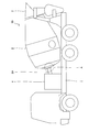
- FIG. 1 is a side view of a mixer truck equipped with a ready-mixed concrete temperature measuring device according to an embodiment of the present invention.
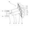
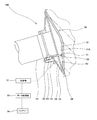
- FIG. 2 is a conceptual diagram showing a ready-mixed concrete temperature measuring apparatus according to an embodiment of the present invention.
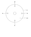
- 3 is a view taken in the direction of arrow B in FIG.
- FIG. 4 is a conceptual diagram showing a first modification of the ready-mixed concrete temperature measuring device according to the embodiment of the present invention.
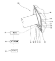
- FIG. 5 is a schematic view showing a second modification of the ready-mixed concrete temperature measuring device according to the embodiment of the present invention.
- FIG. 6 is an enlarged view showing a temperature sensor in a second modification of the ready-mixed concrete temperature measuring apparatus according to the embodiment of the present invention.
- the whole structure of the mixer truck 10 provided with the ready-mixed concrete temperature measuring apparatus 100 is demonstrated.
- the ready-mixed concrete thrown into a mixer drum is represented with a dashed-two dotted line.
- the mixer truck 10 transports ready-mixed concrete (hereinafter referred to as “ready concrete”), which is so-called ready-mixed concrete, on a mixer drum 2 mounted on a gantry 1.
- ready concrete ready-mixed concrete
- the mixer drum 2 is a container that is rotatably mounted on the gantry 1.
- the mixer drum 2 is mounted so that the rotating shaft 2A faces the front-rear direction of the mixer vehicle 10. Further, the mixer drum 2 is mounted so as to be inclined forward and backward so as to gradually increase toward the rear part of the gantry 1.
- the mixer drum 2 has an opening formed at the rear end thereof, and raw material is charged and discharged from the opening. Above the opening of the mixer drum 2, a hopper 3 is provided for charging the raw concrete.
- a double wall portion 20 including an inner gusset 21 as a first wall portion and a bottom wall portion 2 ⁇ / b> B of the mixer drum 2 as a second wall portion is provided at the bottom portion of the mixer drum 2. .
- the inner gusset 21 is an iron plate member and is provided so as to protrude inward from the bottom wall portion 2 ⁇ / b> B that is the bottom wall portion of the mixer drum 2.
- the inner gusset 21 constitutes a part of the wall portion of the mixer drum 2.
- the inner gusset 21 is in contact with the raw concrete and defines an internal space 22 that is blocked from outside air with the bottom wall portion 2B of the mixer drum 2.
- the raw cooker contacts the inner gusset 21 and does not flow into the internal space 22.
- the double wall part 20 is comprised by the inner gusset 21 which contacts a raw concrete, and the bottom wall part 2B provided in the outer side of the inner gusset 21.
- the strength of the bottom of the mixer drum 2 can be improved.
- the mixer drum 2 does not have to be provided with the outer gusset 23. Even in this case, the strength of the bottom of the mixer drum 2 can be improved by increasing the rigidity of the inner gusset 21, for example, by increasing the amount of protrusion of the inner gusset 21 from the bottom of the mixer drum 2.
- the mixer drum 2 is driven by a traveling engine (not shown) mounted on the mixer vehicle 10 as a power source, and is rotated in the forward and reverse directions and increased and decreased by a drum driving device 4 (see FIG. 1) connected to the rotating shaft 2A of the mixer drum 2. To do.
- the drum driving device 4 controls the rotation of the mixer drum 2 according to a command from a controller (not shown) or a command from a control lever (not shown).
- a controller not shown
- a control lever not shown
- the power source for driving the mixer drum 2 is not limited to the traveling engine, and for example, a power source such as an engine for driving the mixer drum 2 may be provided separately.
- the ready-mixed concrete temperature measuring apparatus 100 which measures the temperature of the ready-mixed concrete in the mixer drum 2 is demonstrated.
- the ready-mixed concrete temperature measuring apparatus 100 includes a temperature sensor 30 as a temperature measuring part provided in an inner gusset 21 as a wall part in contact with the ready-mixed concrete, and a temperature sensor provided in a rotating shaft 2 ⁇ / b> A of the mixer drum 2. And a slip ring 31 for supplying power to 30.
- the temperature sensor 30 is a chip-shaped temperature measurement sensor.
- the temperature sensor 30 is attached to the wall surface 21 ⁇ / b> A on the bottom wall portion 2 ⁇ / b> B side of the mixer drum 2, which is an outer wall surface, of the wall surfaces of the inner gusset 21.
- the wall surface 21 ⁇ / b> A is a wall surface of the inner gusset 21 that faces the bottom wall portion 2 ⁇ / b> B of the mixer drum 2.
- the temperature sensor 30 faces the internal space 22 and is provided in the inner gusset 21 in a non-contact manner with the raw concrete.
- the temperature sensor 30 is affixed at four locations on the wall surface 21A of the inner gusset 21 on the outer side in the radial direction and spaced by 90 ° in the circumferential direction.
- the inner gusset 21 is made of iron, the heat of the raw kon is transferred to the inner gusset 21 when the raw kon is introduced into the mixer drum 2.
- the temperature of the inner gusset 21 becomes substantially the same as the temperature of the raw food.
- the temperature sensor 30 affixed to the wall surface 21 ⁇ / b> A of the inner gusset 21 does not directly contact the raw kon, and measures the temperature of the raw kon via the inner gusset 21.
- the slip ring 31 supplies power to the rotating body and transmits signals to and from the rotating body. As shown in FIG. 2, the slip ring 31 is connected to a hollow tube 32 provided on the rotating shaft 2 ⁇ / b> A of the mixer drum 2. The slip ring 31 is electrically connected to the temperature sensor 30 by a wiring 33 passing through the hollow tube 32.
- the slip ring 31 is electrically connected to a battery 34 mounted on the mixer truck 10 and a data processing unit 35 included in the controller.
- the data processing unit 35 stores and calculates the measurement result of the temperature sensor 30.
- the slip ring 31 supplies power from the battery 34 to the temperature sensor 30 attached to the inner gusset 21 of the mixer drum 2. Further, the slip ring 31 receives the temperature measurement result from the temperature sensor 30 and transmits it to the data processing unit 35.
- the engine is started in advance to rotate the mixer drum 2, and a predetermined amount of ready-mixed ingredients is put into the rotating mixer drum 2 through the hopper 3. Due to the rotation of the mixer drum 2, the raw food is stirred in the mixer drum 2. In the mixer vehicle, the mixer drum 2 rotates even during traveling to stir the raw concrete.
- the temperature sensor 30 measures the temperature of the raw food via the inner gusset 21 at a predetermined measurement cycle. Since the ready-mixed concrete temperature measuring apparatus 100 includes the slip ring 31 that can supply power to the rotating body, the power is supplied to the temperature sensor 30 even when the mixer truck 10 is running and the mixer drum 2 is rotating. Can measure the temperature of raw concrete.
- the measurement result measured by the temperature sensor 30 is transmitted to the data processing unit 35 through the slip ring 31 and stored.
- the measurement result transmitted to the data processing unit 35 is transmitted to, for example, a display provided in the driver's seat, and the temperature of the raw control as the measurement result is displayed on the display. Therefore, according to the ready-mixed concrete temperature measuring apparatus 100, the temperature of the ready-mixed concrete in the traveling mixer truck 10 can be grasped.
- the temperature sensor 30 measures the temperature of the raw konset by measuring the temperature of the inner gusset 21 that has become substantially the same as the temperature of the raw cocoon when the heat of the raw kon is transferred.
- the inner gusset 21 is in contact with the live control in the mixer drum 2, but is not in contact with outside air. Therefore, by providing the temperature sensor 30 in the inner gusset 21 so as to face the internal space 22, the temperature sensor 30 is hardly affected by the outside air, and can accurately measure the temperature of the raw control unit.
- the inner gusset 21 is formed as a plate member, the wall surface (the wall surface on the side opposite to the wall surface 21A) that comes into contact with the raw concrete is less uneven and the raw concrete is difficult to adhere. Therefore, since the heat transfer to the inner gusset 21 is not easily disturbed, the temperature of the raw control can be accurately measured by the temperature sensor 30 via the inner gusset 21.
- the temperature sensor 30 is affixed to the wall surface 21A on the side of the internal space 22 where the raw concrete does not flow, it is possible to prevent the raw concrete from adhering in the mixer drum 2 by providing the temperature sensor 30. Furthermore, since the temperature sensors 30 are provided at four locations, for example, by calculating a value obtained by averaging the measurement results of the respective temperature sensors 30, the accuracy of temperature measurement can be improved.
- the temperature sensor 30 measures the temperature of the inner gusset 21 to which the heat of the raw kon is transferred, there may be a difference between the temperature of the raw kon and the measurement result.
- the data processing unit 35 performs an operation for correcting the temperature measurement result based on the accumulated temperature measurement data, and displays the corrected temperature on a display or the like in the driver's seat. May be. By performing an operation for correcting the temperature measurement result, it is possible to calculate a more accurate temperature of the raw control unit.
- the temperature sensor 30 is a chip-shaped temperature measurement sensor. Instead, other temperature sensors such as a thermistor or a sheet-like thermocouple may be used.
- the ready-mixed concrete temperature measuring apparatus 100 transmits a detection result of the temperature sensor 30 by a wireless signal, and a wireless signal transmitted from the transmitter 50.
- a receiver 51 that receives a signal and transmits the signal to the data processing unit 35, and a measurement battery 52 that supplies power to the temperature sensor 30 and the transmitter 50, and without using the slip ring 31, The temperature may be measured.
- the transmitter 50 is provided in the bottom space 24 between the outer gusset 23 inside the mixer drum 2 and the bottom wall 2B of the mixer drum 2.
- the transmitter 50 is electrically connected to the temperature sensor 30 by the wiring 53 and receives a measurement result from the temperature sensor 30.
- the transmitter 50 transmits the received measurement result as a radio signal.
- the receiver 51 is provided outside the mixer drum 2, receives the measurement result of the temperature sensor 30 transmitted as a radio signal from the transmitter 50, and transmits it to the data processing unit 35.
- the measurement result of the temperature sensor 30 is transmitted as a radio signal from the transmitter 50 and input to the data processing unit 35 via the receiver 51. Therefore, since it is not necessary to route the wiring 33 through the hollow tube 32, it can be easily attached to the mixer truck 10.
- the wiring 33 is not damaged by the contact between the hollow tube 32 and the wiring 33, and the temperature measurement of the raw control by the temperature sensor 30 is not disabled. Therefore, a measure for preventing the wiring 33 from being damaged becomes unnecessary, the cost can be reduced, and the attachment property to the mixer truck 10 is further improved.
- the temperature sensor 30 is provided in a sensor cover 130 attached to the tip of the bolt 60.
- the sensor cover 130 has a hemispherical tip 130A, and is formed of a material having high thermal conductivity (for example, aluminum).
- the sensor cover 130 passes through the through hole 2D (see FIG. 6) of the bottom wall portion 2B of the mixer drum 2, and the tip portion 130A contacts the wall surface 21A on the inner space 22 side in the inner gusset 21.
- the temperature sensor 30 is attached to the bottom of the recess 130B formed in the sensor cover 130, and contacts the wall surface 21A of the inner gusset 21 via the tip 130A of the sensor cover 130.
- the bolt 60 and the sensor cover 130 are configured to be extendable (relatively movable in the axial direction) by providing a coil spring (not shown) between them.
- the sensor cover 130 is in contact with the wall surface 21A of the inner gusset 21 by tightening the bolt 60 with the sensor cover 130 being in contact with the wall surface 21A of the inner gusset 21.
- the temperature sensor 30 can be attached.
- the wiring 53 of the temperature sensor 30 is guided to the outside of the outer gusset 23 through a bolt through hole (not shown) formed through the bolt 60 in the axial direction.
- the wiring 53 of the temperature sensor 30 is connected to the transmitter 50 as in the first modification (see FIG. 4).
- the transmitter 50 is attached to the outside of the outer gusset 23 so as to follow the rotation of the mixer drum 2.
- the wiring 53 of the temperature sensor 30 may be connected to the slip ring 31 as in the above embodiment.
- the wiring 53 of the temperature sensor 30 may be connected to the transmitter 50 attached to the inside of the outer gusset 23 as in the first modification, without being led to the outside of the outer gusset 23 through the bolt through hole. That is, the embodiment and the second modification may be combined, or the first modification and the second modification may be combined.
- the temperature sensor 30 is attached to the tip of the bolt 60, and in the inner gusset 21 that comes into contact with the live control unit, by contacting the wall surface 21A opposite to the live control unit via the sensor cover 130. Then, the temperature of the raw control is measured through the inner gusset 21.
- the temperature sensor 30 can be provided by using the bolt 60 for attaching the outer gusset 23, and therefore, compared with a case where a hole for attaching the temperature sensor 30 is separately formed in the outer gusset 23. Thus, strength reduction can be suppressed. Moreover, since the temperature sensor 30 can be easily attached or detached by removing the bolt 60, replacement and maintenance can be easily performed.
- the sensor cover 130 comes into contact with the wall surface 21A through the spherical tip portion 130A and the temperature sensor 30 comes into contact with the wall surface 21A through the tip portion 130A, the sensor cover 130 and the wall surface 21A can be reliably brought into contact with each other. Even if the temperature sensor 30 is configured to be detachable from the outside, the temperature can be reliably measured.
- the temperature sensors 30 are provided at four locations in the circumferential direction with respect to the inner gusset 21. Instead of this, one to three temperature sensors 30 may be provided, or five or more temperature sensors 30 may be provided. Moreover, it is preferable that the temperature sensor 30 is attached to the inner gusset 21 at equal intervals in the circumferential direction. However, the position is not limited to this and may be attached to an arbitrary position.
- the bottom of the mixer drum 2 is provided with the inner gusset 21 inside the bottom wall 2B and the outer gusset 23 outside.
- the temperature sensor 30 is provided in the inner gusset 21 of the mixer drum 2.
- the inner gusset 21 is not provided in the mixer drum 2 and the double wall portion 20 is configured by the outer gusset 23 and the bottom wall portion 2B
- the bottom wall portion 2B of the mixer drum 2 with which the raw concrete comes into contact is formed.
- the temperature sensor 30 may be attached.
- the bottom wall 2B of the mixer drum 2 in contact with the raw concrete is the first wall
- the outer gusset 23 is the second wall.
- the temperature sensor 30 is provided in the inner gusset 21 constituting the double wall portion 20. It replaces with this and the temperature sensor 30 may be provided in the other wall part which a raw concrete contacts.
- the temperature sensor 30 may be provided in the mixer drum 2 and embedded in a blade that stirs the raw material, and the temperature of the raw material may be measured via the blade.
- a cover may be provided on the outer peripheral surface of the mixer drum 2 so as to partition the internal space with the mixer drum 2, and the temperature sensor 30 may be attached to the outer peripheral surface of the mixer drum 2 so as to face the internal space.
- a double wall portion is configured with the wall portion of the mixer drum 2 facing the internal space as the first wall portion and the cover as the second wall portion. Also in this case, since the influence of outside air or the like is suppressed by the cover, the temperature of the raw control can be measured.
- the temperature sensor 30 is attached to the wall surface 21 ⁇ / b> A of the inner gusset 21.
- the temperature sensor 30 may be embedded in the inner gusset 21. In this case, since the temperature can be measured at a position closer to the raw control unit, the temperature of the raw control unit can be measured with higher accuracy.
- the temperature sensor 30 As a case where the temperature sensor 30 is embedded in the inner gusset 21, a notch for accommodating the temperature sensor 30 is provided on a wall surface (a wall surface opposite to the wall surface 21) of the inner gusset 21 that comes into contact with the raw control,
- the sensor 30 may be covered with a resin material or the like.
- the resin material or the like constitutes a part of the wall portion of the mixer drum 2, and the temperature sensor 30 can measure the temperature of the raw control unit without contact with the raw control unit without contact with the raw control unit. .
- the resin material or the like covering the temperature sensor 30 is provided so as not to protrude into the internal space of the mixer drum 2 and to be continuous with the wall surface of the inner gusset 21 so that raw concrete does not adhere.
- the temperature of the raw control can be measured more accurately.
- the temperature sensor 30 is provided on the wall portion of the mixer drum 2 so as to face the raw corn across the inner wall surface in contact with the raw kon, and measures the temperature of the raw kon without contact through the wall. I just need it.
- the temperature measurement unit is the temperature sensor 30 that directly contacts the inner gusset 21.
- the temperature measuring unit may measure the temperature of the inner gusset 21 in a non-contact manner and measure the temperature of the raw control via the inner gusset 21.
- the temperature measurement unit may be a radiation thermometer, a thermography, or the like that measures the surface temperature of the inner gusset 21 in a non-contact manner.
- the non-contact type temperature measuring unit measures a temperature in a measurement region that occupies a certain range, and measures a wide range of temperatures in a measurement object as compared with a contact type such as the temperature sensor 30. Can do. Therefore, by providing the non-contact type temperature measuring unit, it becomes easy to measure the temperature of the raw control unit when the amount of the raw control unit in the mixer drum 2 is different.
- the heat of the ready-mixed konset 21 is transmitted to the inner gusset 21 at the bottom of the mixer drum 2, so that the temperature sensor 30 can measure the temperature of the ready-made kon via the inner gusset 21.
- the temperature sensor 30 measures the temperature of the raw concrete in a non-contact manner via the inner gusset 21 and does not measure the temperature in contact with the raw concrete. Absent. Therefore, it is possible to measure the temperature of the ready-mixed concrete in the mixer drum 2 during transportation while preventing the ready-mixed material from adhering.
- the inner gusset 21 is in contact with the raw concrete in the mixer drum 2, but is not in contact with outside air. For this reason, by providing the temperature sensor 30 in the inner gusset 21 so as to face the internal space 22, the temperature sensor 30 is hardly affected by the outside air, and the temperature of the raw control can be measured with higher accuracy.
- the ready-mixed concrete temperature measuring device 100 for measuring the temperature of the ready-mixed concrete in the mixer drum 2 mounted on the mixer truck 10 is provided so as to face the ready-made concrete in the mixer drum 2 and is in contact with the ready-mixed concrete wall 2 (outer gusset 23). Is provided with a temperature sensor 30 for measuring the temperature of the raw control.
- the temperature sensor 30 measures the temperature of the raw concrete in a non-contact manner through the wall portion (outer gusset 23) of the mixer drum 2, and does not measure the temperature in contact with the raw concrete.
- the raw food is not attached by the sensor 30. Therefore, it is possible to measure the temperature of the raw control unit in the mixer drum 2 during transportation without promoting the adhesion of the raw control unit.
- the mixer drum 2 has a first wall portion (outer gusset 23) in contact with the ready-mixed concrete and a second wall portion (bottom wall) provided outside the first wall portion (outer gusset 23).
- Part 2B) is provided, and the second wall part (bottom wall part 2B) defines an internal space 22 between the first wall part (outer gusset 23) and the temperature.
- the sensor 30 faces the internal space 22 and is provided on the first wall portion (outer gusset 23).
- the double wall portion 20 is provided at the bottom of the mixer drum 2.
- the first wall portion is a plate-like inner gusset 21 provided on the inner wall surface of the bottom portion of the mixer drum 2.
- the temperature sensor 30 is hardly affected by outside air, and measures the temperature of the raw control with higher accuracy. be able to.
- the ready-mixed concrete temperature measuring apparatus 100 further includes a slip ring 31 that is provided on the rotating shaft 2A of the mixer drum 2 and supplies power to the temperature sensor 30.
- the ready-mixed concrete temperature measuring apparatus 100 includes the slip ring 31 that can supply electric power to the rotating body. Therefore, even if the mixer car 10 is traveling and the mixer drum 2 is rotating, electric power is supplied to the temperature sensor 30. And the temperature of the raw control can be measured.
- the ready-mixed concrete temperature measuring apparatus 100 receives a transmitter 50 that is provided in the mixer drum 2 and transmits a measurement result of the temperature sensor 30 by a radio signal, and a radio signal that is provided outside the mixer drum 2 and is transmitted from the transmitter 50. And a receiver 51.
- the measurement result of the temperature sensor 30 is transmitted as a radio signal from the transmitter 50 and received by the receiver 51. Therefore, since it is not necessary to route the wiring 33 through the hollow tube 32, it can be easily attached to the mixer truck 10. Moreover, since it is not necessary to route the wiring 33 through the hollow tube 32, the wiring 33 is not damaged by the contact between the hollow tube 32 and the wiring 33, and the temperature measurement of the raw control by the temperature sensor 30 is not disabled. Therefore, a measure for preventing the wiring 33 from being damaged becomes unnecessary, the cost can be reduced, and the attachability of the ready-mixed concrete temperature measuring device 100 to the mixer truck 10 is further improved.
- the ready-mixed concrete temperature measuring apparatus 100 further includes an outer gusset 23 that is attached to the rotating shaft 2A of the mixer drum 2 via the bolt 60 and covers the bottom of the mixer drum 2 from the outside, and the temperature sensor 30 is attached to the tip of the bolt 60. Then, the temperature of the raw control unit may be measured through the wall part by contacting the wall part (outer gusset 23) of the mixer drum 2 that contacts the raw control unit.
- the temperature sensor 30 can be provided by using the bolt 60 for attaching the outer gusset 23, so that a hole for attaching the temperature sensor 30 is separately formed in the wall portion (outer gusset 23) of the mixer drum 2. Compared with the case, strength reduction can be suppressed. Moreover, since the temperature sensor 30 can be easily attached or detached by removing the bolt 60, replacement and maintenance can be easily performed.
Landscapes
- Physics & Mathematics (AREA)
- General Physics & Mathematics (AREA)
- Engineering & Computer Science (AREA)
- Health & Medical Sciences (AREA)
- Public Health (AREA)
- Transportation (AREA)
- Mechanical Engineering (AREA)
- Measuring Temperature Or Quantity Of Heat (AREA)
- Preparation Of Clay, And Manufacture Of Mixtures Containing Clay Or Cement (AREA)
Abstract
Description
Claims (8)
- ミキサ車に搭載されるミキサドラム内の生コンクリートの温度を測定する生コンクリート温度測定装置であって、
前記ミキサドラム内の生コンクリートと対向して設けられ生コンクリートと接触する前記ミキサドラムの壁部を介して生コンクリートの温度を測定する温度測定部を備える生コンクリート温度測定装置。 - 請求項1に記載の生コンクリート温度測定装置であって、
前記ミキサドラムには、生コンクリートと接触する第一壁部と前記第一壁部の外側に設けられる第二壁部とによって構成される二重壁部が設けられ、
前記第二壁部は、前記第一壁部との間で内部空間を区画し、
前記温度測定部は、前記内部空間に臨んで前記第一壁部に設けられる生コンクリート温度測定装置。 - 請求項2に記載の生コンクリート温度測定装置であって、
前記二重壁部は、前記ミキサドラムの底部に設けられる生コンクリート温度測定装置。 - 請求項3に記載の生コンクリート温度測定装置であって、
前記第一壁部は、前記ミキサドラムにおける底部の内壁面に設けられる板状のインナーガセットである生コンクリート温度測定装置。 - 請求項1から4のいずれか一つに記載の生コンクリート温度測定装置であって、
前記ミキサドラムの回転軸に設けられ前記温度測定部に電力を供給するスリップリングをさらに備える生コンクリート温度測定装置。 - 請求項1から4のいずれか一つに記載の生コンクリート温度測定装置であって、
前記ミキサドラム内に設けられ前記温度測定部の測定結果を無線信号によって送信する送信機と、
前記ミキサドラム外に設けられ前記送信機から送信される前記無線信号を受信する受信機と、をさらに備える生コンクリート温度測定装置。 - 請求項1から6のいずれか一つに記載の生コンクリート温度測定装置であって、
ボルトを介して前記ミキサドラムの回転軸に取り付けられ前記ミキサドラムの底部を外側から覆うアウターガセットをさらに備え、
前記温度測定部は、前記ボルトの先端に取り付けられ、生コンクリートと接触する前記ミキサドラムの前記壁部に接触することにより、前記壁部を介して生コンクリートの温度を測定する生コンクリート温度測定装置。 - 請求項1から7のいずれか一つに記載の生コンクリート温度測定装置を備えるミキサ車。
Priority Applications (1)
| Application Number | Priority Date | Filing Date | Title |
|---|---|---|---|
| AU2016350402A AU2016350402A1 (en) | 2015-11-02 | 2016-10-28 | Ready-mix concrete temperature-measuring device and concrete mixer vehicle equipped with same |
Applications Claiming Priority (2)
| Application Number | Priority Date | Filing Date | Title |
|---|---|---|---|
| JP2015-215999 | 2015-11-02 | ||
| JP2015215999A JP6154877B2 (ja) | 2015-11-02 | 2015-11-02 | 生コンクリート温度測定装置及びこれを備えるミキサ車 |
Publications (1)
| Publication Number | Publication Date |
|---|---|
| WO2017077952A1 true WO2017077952A1 (ja) | 2017-05-11 |
Family
ID=58663027
Family Applications (1)
| Application Number | Title | Priority Date | Filing Date |
|---|---|---|---|
| PCT/JP2016/082012 Ceased WO2017077952A1 (ja) | 2015-11-02 | 2016-10-28 | 生コンクリート温度測定装置及びこれを備えるミキサ車 |
Country Status (3)
| Country | Link |
|---|---|
| JP (1) | JP6154877B2 (ja) |
| AU (1) | AU2016350402A1 (ja) |
| WO (1) | WO2017077952A1 (ja) |
Cited By (1)
| Publication number | Priority date | Publication date | Assignee | Title |
|---|---|---|---|---|
| CN107727273A (zh) * | 2017-09-28 | 2018-02-23 | 中国建筑土木建设有限公司 | 一种高速铁路预制箱梁混凝土温度智能监测方法 |
Families Citing this family (1)
| Publication number | Priority date | Publication date | Assignee | Title |
|---|---|---|---|---|
| KR101949394B1 (ko) * | 2017-10-16 | 2019-05-08 | 주식회사 포스코건설 | 레미콘 트럭 및 그의 통합 관리 시스템 |
Citations (5)
| Publication number | Priority date | Publication date | Assignee | Title |
|---|---|---|---|---|
| JPH01149971U (ja) * | 1988-04-05 | 1989-10-17 | ||
| JP2001009826A (ja) * | 1999-07-02 | 2001-01-16 | Kuretoishi Kk | タンク状容器の冷却用被覆具 |
| JP2008049499A (ja) * | 2006-08-22 | 2008-03-06 | Taiheiyo Cement Corp | アジテータ車および生コンクリート製造管理装置 |
| JP2008246817A (ja) * | 2007-03-30 | 2008-10-16 | Sumitomo Osaka Cement Co Ltd | 生コンクリート運搬用トラックアジテータのドラム温度調整方法、及び生コンクリート運搬用トラックアジテータのドラム温度調整装置 |
| JP2011505525A (ja) * | 2007-11-30 | 2011-02-24 | 本田技研工業株式会社 | 高圧ガス貯蔵装置用の加温システム |
-
2015
- 2015-11-02 JP JP2015215999A patent/JP6154877B2/ja active Active
-
2016
- 2016-10-28 AU AU2016350402A patent/AU2016350402A1/en not_active Abandoned
- 2016-10-28 WO PCT/JP2016/082012 patent/WO2017077952A1/ja not_active Ceased
Patent Citations (5)
| Publication number | Priority date | Publication date | Assignee | Title |
|---|---|---|---|---|
| JPH01149971U (ja) * | 1988-04-05 | 1989-10-17 | ||
| JP2001009826A (ja) * | 1999-07-02 | 2001-01-16 | Kuretoishi Kk | タンク状容器の冷却用被覆具 |
| JP2008049499A (ja) * | 2006-08-22 | 2008-03-06 | Taiheiyo Cement Corp | アジテータ車および生コンクリート製造管理装置 |
| JP2008246817A (ja) * | 2007-03-30 | 2008-10-16 | Sumitomo Osaka Cement Co Ltd | 生コンクリート運搬用トラックアジテータのドラム温度調整方法、及び生コンクリート運搬用トラックアジテータのドラム温度調整装置 |
| JP2011505525A (ja) * | 2007-11-30 | 2011-02-24 | 本田技研工業株式会社 | 高圧ガス貯蔵装置用の加温システム |
Cited By (1)
| Publication number | Priority date | Publication date | Assignee | Title |
|---|---|---|---|---|
| CN107727273A (zh) * | 2017-09-28 | 2018-02-23 | 中国建筑土木建设有限公司 | 一种高速铁路预制箱梁混凝土温度智能监测方法 |
Also Published As
| Publication number | Publication date |
|---|---|
| JP2017087776A (ja) | 2017-05-25 |
| JP6154877B2 (ja) | 2017-06-28 |
| AU2016350402A1 (en) | 2018-05-17 |
Similar Documents
| Publication | Publication Date | Title |
|---|---|---|
| JP6154877B2 (ja) | 生コンクリート温度測定装置及びこれを備えるミキサ車 | |
| JP4984434B2 (ja) | レースタイヤ摩耗予測装置 | |
| JP2010247277A (ja) | ワイヤレス・データ送受信システム | |
| US20130049445A1 (en) | Bicycle rear hub | |
| CN104080624A (zh) | 车轮位置检测装置及具有车轮位置检测装置的轮胎压力检测设备 | |
| JP2006142993A (ja) | 加速度センサ装着タイヤ | |
| WO2016208057A1 (ja) | 車輪位置特定装置 | |
| JP2017087443A (ja) | 生コンクリート温度測定装置及びこれを備えるミキサ車 | |
| CN103958224A (zh) | 车轮位置检测装置以及具有该车轮位置检测装置的轮胎压力检测设备 | |
| JP2014004769A (ja) | 生コンクリートのスランプ値の推定システム及び方法、ミキサ、ミキサ車、及び、生コンクリートのスランプ値の把握システム | |
| US9910407B2 (en) | Image forming apparatus and image forming system | |
| CN102581957A (zh) | 一种搅拌车的随车物料计量指示的控制方法、装置及系统 | |
| JP2012096640A (ja) | センサユニット登録システム及びセンサユニット登録方法 | |
| US12398995B2 (en) | Measuring device for determining a distribution of a heat transfer medium and method for determining a distribution of a heat transfer medium | |
| US7847553B2 (en) | Device consisting of a combination of a magnetic resonance tomograph and a positron emission tomograph | |
| WO2015194577A1 (ja) | ミキサ車管理システム、ミキサ車管理サーバ、ミキサ車及びミキサ車管理方法 | |
| JP2008050101A (ja) | 輸送管理システム | |
| CN107107688B (zh) | 用于控制安装在机动车辆车轮上的电子盒的处理器的方法 | |
| JP2020076599A (ja) | 生コンクリート温度測定装置及びこれを備えるミキサ車 | |
| JP6616575B2 (ja) | 嵌合状態検査装置 | |
| JP2016068529A (ja) | ミキサドラム内の生コンクリート状態検出装置 | |
| JP4677808B2 (ja) | 車輪装着位置判定装置、車輪位置情報設定装置、および車輪情報取得装置 | |
| JPH10189692A (ja) | ウェハズレ検出装置 | |
| US20220316588A1 (en) | Transfer system of work machine, work machine, and method of predicting lifetime of transfer system in work machine | |
| KR20170067553A (ko) | 변속기의 토크 측정 장치 |
Legal Events
| Date | Code | Title | Description |
|---|---|---|---|
| 121 | Ep: the epo has been informed by wipo that ep was designated in this application |
Ref document number: 16862012 Country of ref document: EP Kind code of ref document: A1 |
|
| NENP | Non-entry into the national phase |
Ref country code: DE |
|
| ENP | Entry into the national phase |
Ref document number: 2016350402 Country of ref document: AU Date of ref document: 20161028 Kind code of ref document: A |
|
| 122 | Ep: pct application non-entry in european phase |
Ref document number: 16862012 Country of ref document: EP Kind code of ref document: A1 |