WO2017069290A1 - 作業機械の加工状態監視方法及びシステム - Google Patents
作業機械の加工状態監視方法及びシステム Download PDFInfo
- Publication number
- WO2017069290A1 WO2017069290A1 PCT/JP2016/082499 JP2016082499W WO2017069290A1 WO 2017069290 A1 WO2017069290 A1 WO 2017069290A1 JP 2016082499 W JP2016082499 W JP 2016082499W WO 2017069290 A1 WO2017069290 A1 WO 2017069290A1
- Authority
- WO
- WIPO (PCT)
- Prior art keywords
- peak
- threshold
- tpf
- frequency
- tool
- Prior art date
- Legal status (The legal status is an assumption and is not a legal conclusion. Google has not performed a legal analysis and makes no representation as to the accuracy of the status listed.)
- Ceased
Links
Images


Classifications
-
- B—PERFORMING OPERATIONS; TRANSPORTING
- B23—MACHINE TOOLS; METAL-WORKING NOT OTHERWISE PROVIDED FOR
- B23Q—DETAILS, COMPONENTS, OR ACCESSORIES FOR MACHINE TOOLS, e.g. ARRANGEMENTS FOR COPYING OR CONTROLLING; MACHINE TOOLS IN GENERAL CHARACTERISED BY THE CONSTRUCTION OF PARTICULAR DETAILS OR COMPONENTS; COMBINATIONS OR ASSOCIATIONS OF METAL-WORKING MACHINES, NOT DIRECTED TO A PARTICULAR RESULT
- B23Q15/00—Automatic control or regulation of feed movement, cutting velocity or position of tool or work
- B23Q15/007—Automatic control or regulation of feed movement, cutting velocity or position of tool or work while the tool acts upon the workpiece
- B23Q15/12—Adaptive control, i.e. adjusting itself to have a performance which is optimum according to a preassigned criterion
-
- B—PERFORMING OPERATIONS; TRANSPORTING
- B23—MACHINE TOOLS; METAL-WORKING NOT OTHERWISE PROVIDED FOR
- B23Q—DETAILS, COMPONENTS, OR ACCESSORIES FOR MACHINE TOOLS, e.g. ARRANGEMENTS FOR COPYING OR CONTROLLING; MACHINE TOOLS IN GENERAL CHARACTERISED BY THE CONSTRUCTION OF PARTICULAR DETAILS OR COMPONENTS; COMBINATIONS OR ASSOCIATIONS OF METAL-WORKING MACHINES, NOT DIRECTED TO A PARTICULAR RESULT
- B23Q17/00—Arrangements for observing, indicating or measuring on machine tools
- B23Q17/10—Arrangements for observing, indicating or measuring on machine tools for indicating or measuring cutting speed or number of revolutions
-
- B—PERFORMING OPERATIONS; TRANSPORTING
- B23—MACHINE TOOLS; METAL-WORKING NOT OTHERWISE PROVIDED FOR
- B23Q—DETAILS, COMPONENTS, OR ACCESSORIES FOR MACHINE TOOLS, e.g. ARRANGEMENTS FOR COPYING OR CONTROLLING; MACHINE TOOLS IN GENERAL CHARACTERISED BY THE CONSTRUCTION OF PARTICULAR DETAILS OR COMPONENTS; COMBINATIONS OR ASSOCIATIONS OF METAL-WORKING MACHINES, NOT DIRECTED TO A PARTICULAR RESULT
- B23Q17/00—Arrangements for observing, indicating or measuring on machine tools
- B23Q17/12—Arrangements for observing, indicating or measuring on machine tools for indicating or measuring vibration
-
- G—PHYSICS
- G05—CONTROLLING; REGULATING
- G05B—CONTROL OR REGULATING SYSTEMS IN GENERAL; FUNCTIONAL ELEMENTS OF SUCH SYSTEMS; MONITORING OR TESTING ARRANGEMENTS FOR SUCH SYSTEMS OR ELEMENTS
- G05B19/00—Program-control systems
- G05B19/02—Program-control systems electric
- G05B19/18—Numerical control [NC], i.e. automatically operating machines, in particular machine tools, e.g. in a manufacturing environment, so as to execute positioning, movement or co-ordinated operations by means of program data in numerical form
- G05B19/406—Numerical control [NC], i.e. automatically operating machines, in particular machine tools, e.g. in a manufacturing environment, so as to execute positioning, movement or co-ordinated operations by means of program data in numerical form characterised by monitoring or safety
- G05B19/4063—Monitoring general control system
Definitions
- the present invention relates to a processing state monitoring method and a system for a working machine for monitoring a processing state by the processing tool when the processing tool or workpiece is rotated to perform processing on the workpiece through the processing tool. .
- various machine tools are used to process a workpiece through a processing tool.
- a boring tool provided with a boring tool (cutting edge) is attached to a rotating spindle (spindle) of a machine tool, and the boring tool is sequentially fed along a pilot hole while rotating at a high speed.
- a highly accurate hole is processed at a predetermined position with the cutting edge diameter.
- Patent Document 1 proposes a vibration discriminating method and a vibration discriminating apparatus that can discriminate the type of chatter vibration with high accuracy.
- the first step of detecting the vibration in the time domain of the rotating rotating shaft and the rotation speed of the rotating shaft, and the vibration in the frequency domain are calculated based on the vibration in the time domain.
- the type of chatter vibration based on the relationship between the third step determined using the peak frequency and the rotation frequency determination range determined using the peak frequency and the peak frequency for each peak value.
- a fourth step of discriminating the above the first step of detecting the vibration in the time domain of the rotating rotating shaft and the rotation speed of the rotating shaft, and the vibration in the frequency domain are calculated based on the vibration in the time domain.
- Patent Document 1 described above, after chatter actually occurs, the type of chatter vibration is determined. Therefore, since the processing for the generated chatter vibration is performed, the influence of the chatter vibration is generated on the work member, and there is a possibility that a highly accurate machining process may not be performed.
- the present invention solves this type of problem, and with a simple process and configuration, it is possible to perform a good response before the occurrence of chatter, and to prevent the occurrence of chatter as much as possible. It is an object of the present invention to provide a machining state monitoring method and system for a work machine capable of efficiently performing accurate machining operations.
- the present invention relates to a processing state monitoring method and a system for a working machine for monitoring a processing state by the processing tool when the processing tool or workpiece is rotated to perform processing on the workpiece through the processing tool. Is.
- This machining state monitoring method is a frequency spectrum comprising a step of inputting the rotation number, the number of blades and the natural frequency of a machining tool, and a frequency and acceleration obtained by analyzing the vibration of the machining tool or workpiece during machining by Fourier series expansion. And a TPF peak that is a peak acceleration at the tool passing frequency calculated from the number of rotations and the number of blades is compared with a TPF threshold that is a peak threshold of the tool passing frequency preset in the frequency spectrum. The number of times that the TPF peak has exceeded the TPF threshold is displayed on the TPF threshold value exceeding integrated display section, and the f0 peak that is the peak acceleration at the natural frequency is preset in the frequency spectrum.
- the number of times that the f0 peak exceeds the f0 threshold is compared with the f0 threshold that is the peak threshold of the natural frequency.
- the step of setting the vibration at the time of idling of the machine spindle as a threshold the step of determining whether or not the machining vibration detected during machining of the machine spindle exceeds the threshold, And a step of analyzing the vibration of the machining tool or the workpiece by Fourier series expansion when it is determined that the machining vibration exceeds the threshold value.
- the machining state monitoring system includes an input setting unit for inputting the rotation number, the number of blades, and the natural frequency of the machining tool, and the frequency and acceleration obtained by analyzing the vibration of the machining tool or the workpiece during machining by Fourier series expansion.
- a frequency spectrum display unit for displaying a frequency spectrum comprising: a TPF peak that is a peak acceleration at a tool passing frequency calculated from the rotation speed and the number of blades, and a peak of a tool passing frequency preset in the frequency spectrum.
- a TPF threshold value exceeding display section for displaying the number of times the TPF peak has exceeded the TPF threshold value, and an f0 peak value representing the peak acceleration at the natural frequency are preliminarily added to the frequency spectrum.
- the f0 peak is compared with the f0 threshold value, which is the peak threshold value of the set natural frequency.
- the correlation between the peak occurrence frequency at the tool passing frequency (TPF) and the peak occurrence frequency at the natural frequency is obtained.
- TPF tool passing frequency
- 1 is a schematic explanatory diagram of a work machine to which a work machine monitoring state monitoring system according to an embodiment of the present invention is applied. It is explanatory drawing of the controller which comprises the said process state monitoring system. It is a structure explanatory drawing of the display unit which comprises the said process state monitoring system. It is explanatory drawing which shows the change of the process state of a workpiece
- a working machine monitoring state system 10 As shown in FIG. 1, a working machine monitoring state system 10 according to an embodiment of the present invention is applied to a machine tool 12.
- the machine tool 12 includes a spindle (main shaft) 18 that is rotatably provided in a housing 14 via a bearing 16, and a boring bar (processing tool) 20 that is detachably attached to the spindle 18.
- a boring bar 22 is attached to the tip of the boring bar 20.
- a work W is placed on the work table 24.
- the machining state monitoring system 10 includes an acceleration sensor 26 attached to the side of the housing 14 or a microphone 28 that obtains vibration sound using sound waves in order to detect vibration generated when machining by the boring bar 20 is started. At least one is provided.
- the acceleration sensor 26 and / or the microphone 28 are connected to a controller 30, and the controller 30 is connected to a machine control panel 32.
- the machine control panel 32 controls the machine tool 12 and is connected to the control operation panel 34.
- the controller 30 includes an arithmetic unit (arithmetic mechanism) 38 that amplifies and takes in mechanical vibration (machining vibration) detected by the acceleration sensor 26 and / or the microphone 28 by an amplifier and filter circuit 36. Prepare.
- the calculation unit 38 is connected to an input setting unit (input setting unit) 40 for inputting the number of rotations of the spindle 18, the number of blades of the cutting tool 22, the natural frequency, and the like.
- an input setting unit 40 for inputting the number of rotations of the spindle 18, the number of blades of the cutting tool 22, the natural frequency, and the like.
- values such as a predictive threshold value and a warning threshold value for monitoring and identification determination can be set.
- the processing unit 38 is connected to the processing state determination unit 44 and an output unit 46 for outputting a spindle rotation speed adjusted by arithmetic processing described later and a count-up signal exceeding a threshold value.
- the calculation unit 38 is connected to a display unit 48 that displays calculation results and detection results on the screen.
- the display unit 48 includes a first total power display unit 50a, a second total power display unit 50b, a frequency spectrum display unit 52, a frequency flow display unit 54, an over-threshold integration display unit 56, and a change display unit. 58. These are displayed on a single display screen, and a detailed description of each will be described later.
- the spindle 18 to which the boring bar 20 is attached is driven to rotate along the prepared hole Wa of the workpiece W. Then, the boring bar 20 moves relatively to the prepared hole Wa side of the workpiece W. For this reason, the boring bar 20 rotates, and boring is performed on the inner wall surface constituting the prepared hole Wa via the cutting tool 22 attached to the boring bar 20.
- the vibration at the time of idling of the spindle 18 is acquired by the acceleration sensor 26 and / or the microphone 28, and this value is set as an allowable value (threshold value). Then, when the machining is started by the spindle 18 and the machining vibration taken in via the amplifier and filter circuit 36 exceeds an allowable value, arithmetic analysis by Fourier transform (Fourier series expansion) is performed. Specifically, the temporal vibration f (t) is
- f (t) ⁇ (a j cos2 ⁇ Jt + b j sin2 ⁇ Jt).
- a j is the cosine harmonic component Fourier coefficient of frequency J
- b j is the sine harmonic component Fourier coefficient of frequency J.
- the integration interval is 0 to T, and the integration interval T is an integer multiple of the period 1 / J. Here, it is limited to the frequency at which chatter actually occurs, for example, 10 Hz to 10,000 Hz.
- the total power indicated by the sum of the values (G 2 ) obtained by squaring the acceleration (G) of the machining vibration is displayed on the first total power display unit 50a and the second total power display unit 50b.
- the first total power display section 50a the sum of values obtained by squaring acceleration is displayed on the vertical axis, and the elapsed time in seconds is displayed on the horizontal axis (short-time display).
- the second total power display unit 50b the sum of values obtained by squaring acceleration is displayed on the vertical axis, and the elapsed time in minutes is displayed on the horizontal axis (long-time display).
- the vibration of the total power it is possible to set a two-stage setting of a predictive threshold value and a warning threshold value set separately. Further, when machining vibration exceeding a threshold value occurs during machining, the signal is selectively output to the outside through the output unit 46.
- the display unit 48 is provided with a frequency spectrum display unit 52.
- the frequency spectrum display unit 52 displays a frequency spectrum having the frequency Hz calculated by Fourier analysis on the horizontal axis and the acceleration G on the vertical axis. Also in this frequency spectrum display unit 52, two threshold values are set: a predictive threshold value for acquiring change data corresponding to the peak frequency of machining vibration, and a warning threshold value as an alarm when an abnormal frequency peak appears. Is done.
- the count-up signal is sent to the threshold excess integration display unit 56 and displayed on the laminated graph.
- TPF tool passing frequency
- f0 natural frequency
- FIG. 4 shows machining vibrations when boring with a multi-blade.
- the vertical axis is the acceleration G, which is the magnitude of the vibration amount, and the horizontal axis is time.
- the left side is the machining start point, and represents the machining state without chattering until the middle of machining. Then, it is recognized that the chatter state is reached when the acceleration G exceeds ⁇ 1 G during the machining.
- TPF time of rotations of the spindle / 60
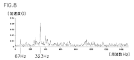
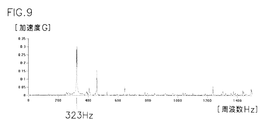
- chatter vibration will be described with reference to FIGS. 5 to 9 are explanatory diagrams of frequency spectra obtained by Fourier transforming vibrations.
- the vertical axis represents vibration acceleration G, and the horizontal axis represents frequency Hz.
- FIG. 5 shows a frequency spectrum for a while after the start of machining in the boring process shown in FIG. This is a state without chatter, and the spectrum has a peak acceleration at 67 Hz which is the frequency of TPF.
- the acceleration of this vibration is as small as 0.015 G, and normal cutting without chatter is performed.
- TPF peak acceleration
- the peak acceleration of 323 Hz which is the natural frequency
- This peak acceleration is as low as about 0.04 G, is a sign of chatter, and is not considered to be a complete chatter state.
- the peak acceleration is maintained at about 0.013 G, but it is difficult to discriminate because the vibration peak of the natural frequency is abruptly exceeding 0.04 G.
- the vibration of the TPF appears as a large amount of cutting vibration.
- the vibration of the natural frequency appears larger than the vibration of the TPF.
- TPF and natural frequency By monitoring the transition of peak acceleration of TPF and natural frequency, the predictive period of chatter can be determined.
- the natural frequency which is one of the monitoring parameters
- the natural frequency can be detected by an impact excitation method using an FFT analyzer. It can also be calculated from the vibration frequency of the already acquired vibration.
- the TPF which is one of the monitoring parameters, is calculated from the number of rotations of the spindle 18 and the number of blades of the cutting tool 22, so the rotation number and the number of blades are input to the input setting unit 40.
- the spindle 18 rotates and the workpiece W is machined, and a frequency spectrum composed of the frequency and acceleration obtained by analyzing the machining vibration by Fourier series expansion is obtained. Then, the peak acceleration (TPF peak) at the tool passing frequency is compared with the tool passing frequency peak threshold (TPF threshold) preset in the frequency spectrum. The number of times that the TPF peak has exceeded the TPF threshold value is displayed in the TPF display field 56 a of the threshold value excess display section 56.
- the peak acceleration (f0 peak) at the natural frequency is compared with the peak threshold value (f0 threshold value) of the natural frequency preset in the frequency spectrum.
- the number of times that the f0 peak has exceeded the f0 threshold value is displayed in the natural frequency display field 56b of the threshold value exceeding integrated display section 56.
- the change display unit 58 displays the TPF threshold value exceeding number and the f0 threshold value exceeding number in comparison. Specifically, the change ratio of the number of times of exceeding the f0 threshold value / the number of times of exceeding the TPF threshold value is instantaneously determined in order of time and displayed on a chart. Parameters to be compared in this chart can be set on a separate screen including gain selection that can weight the integrated values of the number of times exceeding the threshold.
- the change ratio displayed on the change display unit 58 exceeds a predetermined value, it can be determined that the chatter state is present. Further, when the change ratio exceeds a certain value, it is also possible to immediately apply feedback for avoiding chatter by changing the rotation speed or changing the feed speed.
- the correlation between the number of peak occurrences at the tool passing frequency (TPF) and the number of peak occurrences at the natural frequency is observed. Can do. From the change ratio of the relationship between the two, for example, it is possible to quickly and accurately determine that the workpiece processing is in a predictive period in which the workpiece is shifted from the normal state to chatter vibration (abnormal state). For this reason, it can respond quickly and effectively before chatter vibration occurs.
- TPF tool passing frequency
- the change display unit 58 displays the TPF threshold value exceeding number and the f0 threshold value exceeding number for comparison. Therefore, the machining state can be visually confirmed in real time, and it becomes a criterion for judging the accuracy of judgment criteria, error judgment, and the like, and the workability can be easily improved.
Landscapes
- Engineering & Computer Science (AREA)
- Mechanical Engineering (AREA)
- Human Computer Interaction (AREA)
- Manufacturing & Machinery (AREA)
- Physics & Mathematics (AREA)
- General Physics & Mathematics (AREA)
- Automation & Control Theory (AREA)
- Automatic Control Of Machine Tools (AREA)
- Numerical Control (AREA)
- Machine Tool Sensing Apparatuses (AREA)
Applications Claiming Priority (2)
| Application Number | Priority Date | Filing Date | Title |
|---|---|---|---|
| JP2015-218880 | 2015-10-20 | ||
| JP2015218880A JP6575814B2 (ja) | 2015-10-20 | 2015-10-20 | 作業機械の加工状態監視方法及びシステム |
Publications (1)
| Publication Number | Publication Date |
|---|---|
| WO2017069290A1 true WO2017069290A1 (ja) | 2017-04-27 |
Family
ID=58557594
Family Applications (1)
| Application Number | Title | Priority Date | Filing Date |
|---|---|---|---|
| PCT/JP2016/082499 Ceased WO2017069290A1 (ja) | 2015-10-20 | 2016-10-17 | 作業機械の加工状態監視方法及びシステム |
Country Status (2)
| Country | Link |
|---|---|
| JP (1) | JP6575814B2 (https=) |
| WO (1) | WO2017069290A1 (https=) |
Cited By (2)
| Publication number | Priority date | Publication date | Assignee | Title |
|---|---|---|---|---|
| WO2018062445A1 (ja) * | 2016-09-28 | 2018-04-05 | エヌティーエンジニアリング株式会社 | 作業機械の振動監視方法及びシステム |
| WO2021075584A1 (ja) * | 2019-10-18 | 2021-04-22 | エヌティーエンジニアリング株式会社 | 作業機械の加工状態監視方法及びシステム |
Families Citing this family (5)
| Publication number | Priority date | Publication date | Assignee | Title |
|---|---|---|---|---|
| JP7084242B2 (ja) * | 2018-07-30 | 2022-06-14 | Dmg森精機株式会社 | 工具刃数推定装置およびこれを備えた工作機械、ならびに工具刃数推定方法 |
| JP2020055052A (ja) * | 2018-09-28 | 2020-04-09 | シチズン時計株式会社 | 工作機械及びその作動方法 |
| JP7058210B2 (ja) * | 2018-12-10 | 2022-04-21 | Dmg森精機株式会社 | 工作機械、欠損検知方法、および欠損検知プログラム |
| JP6944103B2 (ja) * | 2019-10-22 | 2021-10-06 | エヌティーエンジニアリング株式会社 | 作業機械の加工状態監視方法及びシステム |
| JP7796811B1 (ja) | 2024-06-17 | 2026-01-09 | Dmg森精機株式会社 | 工作機械 |
Citations (4)
| Publication number | Priority date | Publication date | Assignee | Title |
|---|---|---|---|---|
| JP2013000837A (ja) * | 2011-06-16 | 2013-01-07 | Okuma Corp | 振動判別方法、及び振動判別装置 |
| JP2014083674A (ja) * | 2012-10-23 | 2014-05-12 | Nt Engineering Kk | 作業機械のびびり抑制方法 |
| JP2014140918A (ja) * | 2013-01-23 | 2014-08-07 | Hitachi Ltd | 切削振動抑止方法、演算制御装置、および工作機械 |
| JP2016083759A (ja) * | 2014-10-28 | 2016-05-19 | エヌティーエンジニアリング株式会社 | 作業機械の加工状態監視方法及びシステム |
Family Cites Families (2)
| Publication number | Priority date | Publication date | Assignee | Title |
|---|---|---|---|---|
| JP5807437B2 (ja) * | 2011-08-10 | 2015-11-10 | 株式会社ジェイテクト | びびり振動検出装置 |
| KR102191166B1 (ko) * | 2013-06-10 | 2020-12-16 | 두산공작기계 주식회사 | 회전 절삭공구의 실시간 회전수 설정방법 및 제어장치 |
-
2015
- 2015-10-20 JP JP2015218880A patent/JP6575814B2/ja active Active
-
2016
- 2016-10-17 WO PCT/JP2016/082499 patent/WO2017069290A1/ja not_active Ceased
Patent Citations (4)
| Publication number | Priority date | Publication date | Assignee | Title |
|---|---|---|---|---|
| JP2013000837A (ja) * | 2011-06-16 | 2013-01-07 | Okuma Corp | 振動判別方法、及び振動判別装置 |
| JP2014083674A (ja) * | 2012-10-23 | 2014-05-12 | Nt Engineering Kk | 作業機械のびびり抑制方法 |
| JP2014140918A (ja) * | 2013-01-23 | 2014-08-07 | Hitachi Ltd | 切削振動抑止方法、演算制御装置、および工作機械 |
| JP2016083759A (ja) * | 2014-10-28 | 2016-05-19 | エヌティーエンジニアリング株式会社 | 作業機械の加工状態監視方法及びシステム |
Cited By (3)
| Publication number | Priority date | Publication date | Assignee | Title |
|---|---|---|---|---|
| WO2018062445A1 (ja) * | 2016-09-28 | 2018-04-05 | エヌティーエンジニアリング株式会社 | 作業機械の振動監視方法及びシステム |
| WO2021075584A1 (ja) * | 2019-10-18 | 2021-04-22 | エヌティーエンジニアリング株式会社 | 作業機械の加工状態監視方法及びシステム |
| JP2021066006A (ja) * | 2019-10-18 | 2021-04-30 | エヌティーエンジニアリング株式会社 | 作業機械の加工状態監視方法及びシステム |
Also Published As
| Publication number | Publication date |
|---|---|
| JP6575814B2 (ja) | 2019-09-18 |
| JP2017077618A (ja) | 2017-04-27 |
Similar Documents
| Publication | Publication Date | Title |
|---|---|---|
| JP6575814B2 (ja) | 作業機械の加工状態監視方法及びシステム | |
| JP6718107B2 (ja) | 作業機械の振動監視方法及びシステム | |
| KR101300301B1 (ko) | 작업 기계의 채터링 억제 방법 및 장치 | |
| JP5288318B1 (ja) | 作業機械のびびり抑制方法 | |
| JP5525411B2 (ja) | 振動抑制方法及び振動抑制装置 | |
| JP2016083759A (ja) | 作業機械の加工状態監視方法及びシステム | |
| CN101310921B (zh) | 机床的振动抑制装置和振动抑制方法 | |
| JP5536611B2 (ja) | 工作機械のモニタ方法及びモニタ装置、工作機械 | |
| CN114555291B (zh) | 作业机械的加工状态监视方法以及系统 | |
| CN114555292B (zh) | 作业机械的加工状态监视方法以及系统 | |
| JP7084242B2 (ja) | 工具刃数推定装置およびこれを備えた工作機械、ならびに工具刃数推定方法 | |
| JPWO2020157818A1 (ja) | 診断装置及びこれを備えた設備並びに診断方法 | |
| WO2022080505A1 (ja) | 作業機械の工具損傷判定方法及びシステム | |
| JP5637840B2 (ja) | 振動検出方法 | |
| JP7589505B2 (ja) | 診断装置、診断方法、プログラム、および加工システム | |
| JP5660850B2 (ja) | 振動表示装置 | |
| JP2021086588A (ja) | 診断装置、診断装置の制御方法およびプログラム | |
| WO2023063435A1 (ja) | 作業機械のベアリング良否判定方法及びシステム | |
| Sghir et al. | Milling cutting tool diagnosis using comparisons of the excitation identified by cepstral techniques | |
| Sghir et al. | WSVVSXQ LUTTSXQ TYYV NSJQXYSSS USSXQ LYW [JRSSYXS YP TRO OXLSTJTSYX SNOXTSPSON KY LO [STRJV TOLRXS\UOS |
Legal Events
| Date | Code | Title | Description |
|---|---|---|---|
| 121 | Ep: the epo has been informed by wipo that ep was designated in this application |
Ref document number: 16857599 Country of ref document: EP Kind code of ref document: A1 |
|
| NENP | Non-entry into the national phase |
Ref country code: DE |
|
| 122 | Ep: pct application non-entry in european phase |
Ref document number: 16857599 Country of ref document: EP Kind code of ref document: A1 |