WO2017069232A1 - 粒子状物質検出装置 - Google Patents
粒子状物質検出装置 Download PDFInfo
- Publication number
- WO2017069232A1 WO2017069232A1 PCT/JP2016/081241 JP2016081241W WO2017069232A1 WO 2017069232 A1 WO2017069232 A1 WO 2017069232A1 JP 2016081241 W JP2016081241 W JP 2016081241W WO 2017069232 A1 WO2017069232 A1 WO 2017069232A1
- Authority
- WO
- WIPO (PCT)
- Prior art keywords
- temperature
- particulate matter
- element unit
- heater
- period
- Prior art date
- Legal status (The legal status is an assumption and is not a legal conclusion. Google has not performed a legal analysis and makes no representation as to the accuracy of the status listed.)
- Ceased
Links
Images

Classifications
-
- F—MECHANICAL ENGINEERING; LIGHTING; HEATING; WEAPONS; BLASTING
- F01—MACHINES OR ENGINES IN GENERAL; ENGINE PLANTS IN GENERAL; STEAM ENGINES
- F01N—GAS-FLOW SILENCERS OR EXHAUST APPARATUS FOR MACHINES OR ENGINES IN GENERAL; GAS-FLOW SILENCERS OR EXHAUST APPARATUS FOR INTERNAL-COMBUSTION ENGINES
- F01N3/00—Exhaust or silencing apparatus having means for purifying, rendering innocuous, or otherwise treating exhaust
- F01N3/02—Exhaust or silencing apparatus having means for purifying, rendering innocuous, or otherwise treating exhaust for cooling, or for removing solid constituents of, exhaust
- F01N3/021—Exhaust or silencing apparatus having means for purifying, rendering innocuous, or otherwise treating exhaust for cooling, or for removing solid constituents of, exhaust by means of filters
- F01N3/023—Exhaust or silencing apparatus having means for purifying, rendering innocuous, or otherwise treating exhaust for cooling, or for removing solid constituents of, exhaust by means of filters using means for regenerating the filters, e.g. by burning trapped particles
-
- F—MECHANICAL ENGINEERING; LIGHTING; HEATING; WEAPONS; BLASTING
- F01—MACHINES OR ENGINES IN GENERAL; ENGINE PLANTS IN GENERAL; STEAM ENGINES
- F01N—GAS-FLOW SILENCERS OR EXHAUST APPARATUS FOR MACHINES OR ENGINES IN GENERAL; GAS-FLOW SILENCERS OR EXHAUST APPARATUS FOR INTERNAL-COMBUSTION ENGINES
- F01N11/00—Monitoring or diagnostic devices for exhaust-gas treatment apparatus
-
- F—MECHANICAL ENGINEERING; LIGHTING; HEATING; WEAPONS; BLASTING
- F01—MACHINES OR ENGINES IN GENERAL; ENGINE PLANTS IN GENERAL; STEAM ENGINES
- F01N—GAS-FLOW SILENCERS OR EXHAUST APPARATUS FOR MACHINES OR ENGINES IN GENERAL; GAS-FLOW SILENCERS OR EXHAUST APPARATUS FOR INTERNAL-COMBUSTION ENGINES
- F01N3/00—Exhaust or silencing apparatus having means for purifying, rendering innocuous, or otherwise treating exhaust
-
- F—MECHANICAL ENGINEERING; LIGHTING; HEATING; WEAPONS; BLASTING
- F01—MACHINES OR ENGINES IN GENERAL; ENGINE PLANTS IN GENERAL; STEAM ENGINES
- F01N—GAS-FLOW SILENCERS OR EXHAUST APPARATUS FOR MACHINES OR ENGINES IN GENERAL; GAS-FLOW SILENCERS OR EXHAUST APPARATUS FOR INTERNAL-COMBUSTION ENGINES
- F01N3/00—Exhaust or silencing apparatus having means for purifying, rendering innocuous, or otherwise treating exhaust
- F01N3/02—Exhaust or silencing apparatus having means for purifying, rendering innocuous, or otherwise treating exhaust for cooling, or for removing solid constituents of, exhaust
- F01N3/021—Exhaust or silencing apparatus having means for purifying, rendering innocuous, or otherwise treating exhaust for cooling, or for removing solid constituents of, exhaust by means of filters
- F01N3/023—Exhaust or silencing apparatus having means for purifying, rendering innocuous, or otherwise treating exhaust for cooling, or for removing solid constituents of, exhaust by means of filters using means for regenerating the filters, e.g. by burning trapped particles
- F01N3/027—Exhaust or silencing apparatus having means for purifying, rendering innocuous, or otherwise treating exhaust for cooling, or for removing solid constituents of, exhaust by means of filters using means for regenerating the filters, e.g. by burning trapped particles using electric or magnetic heating means
-
- F—MECHANICAL ENGINEERING; LIGHTING; HEATING; WEAPONS; BLASTING
- F01—MACHINES OR ENGINES IN GENERAL; ENGINE PLANTS IN GENERAL; STEAM ENGINES
- F01N—GAS-FLOW SILENCERS OR EXHAUST APPARATUS FOR MACHINES OR ENGINES IN GENERAL; GAS-FLOW SILENCERS OR EXHAUST APPARATUS FOR INTERNAL-COMBUSTION ENGINES
- F01N9/00—Electrical control of exhaust gas treating apparatus
- F01N9/002—Electrical control of exhaust gas treating apparatus of filter regeneration
-
- F—MECHANICAL ENGINEERING; LIGHTING; HEATING; WEAPONS; BLASTING
- F02—COMBUSTION ENGINES; HOT-GAS OR COMBUSTION-PRODUCT ENGINE PLANTS
- F02D—CONTROLLING COMBUSTION ENGINES
- F02D41/00—Electrical control of supply of combustible mixture or its constituents
- F02D41/02—Circuit arrangements for generating control signals
- F02D41/14—Introducing closed-loop corrections
- F02D41/1438—Introducing closed-loop corrections using means for determining characteristics of the combustion gases; Sensors therefor
- F02D41/1444—Introducing closed-loop corrections using means for determining characteristics of the combustion gases; Sensors therefor characterised by the characteristics of the combustion gases
- F02D41/1466—Introducing closed-loop corrections using means for determining characteristics of the combustion gases; Sensors therefor characterised by the characteristics of the combustion gases the characteristics being a soot concentration or content
-
- F—MECHANICAL ENGINEERING; LIGHTING; HEATING; WEAPONS; BLASTING
- F02—COMBUSTION ENGINES; HOT-GAS OR COMBUSTION-PRODUCT ENGINE PLANTS
- F02D—CONTROLLING COMBUSTION ENGINES
- F02D41/00—Electrical control of supply of combustible mixture or its constituents
- F02D41/02—Circuit arrangements for generating control signals
- F02D41/14—Introducing closed-loop corrections
- F02D41/1438—Introducing closed-loop corrections using means for determining characteristics of the combustion gases; Sensors therefor
- F02D41/1493—Details
- F02D41/1494—Control of sensor heater
-
- G—PHYSICS
- G01—MEASURING; TESTING
- G01N—INVESTIGATING OR ANALYSING MATERIALS BY DETERMINING THEIR CHEMICAL OR PHYSICAL PROPERTIES
- G01N15/00—Investigating characteristics of particles; Investigating permeability, pore-volume or surface-area of porous materials
- G01N15/06—Investigating concentration of particle suspensions
-
- G—PHYSICS
- G01—MEASURING; TESTING
- G01N—INVESTIGATING OR ANALYSING MATERIALS BY DETERMINING THEIR CHEMICAL OR PHYSICAL PROPERTIES
- G01N15/00—Investigating characteristics of particles; Investigating permeability, pore-volume or surface-area of porous materials
- G01N15/06—Investigating concentration of particle suspensions
- G01N15/0606—Investigating concentration of particle suspensions by collecting particles on a support
-
- G—PHYSICS
- G01—MEASURING; TESTING
- G01N—INVESTIGATING OR ANALYSING MATERIALS BY DETERMINING THEIR CHEMICAL OR PHYSICAL PROPERTIES
- G01N15/00—Investigating characteristics of particles; Investigating permeability, pore-volume or surface-area of porous materials
- G01N15/06—Investigating concentration of particle suspensions
- G01N15/0656—Investigating concentration of particle suspensions using electric, e.g. electrostatic methods or magnetic methods
-
- G—PHYSICS
- G01—MEASURING; TESTING
- G01N—INVESTIGATING OR ANALYSING MATERIALS BY DETERMINING THEIR CHEMICAL OR PHYSICAL PROPERTIES
- G01N27/00—Investigating or analysing materials by the use of electric, electrochemical, or magnetic means
- G01N27/02—Investigating or analysing materials by the use of electric, electrochemical, or magnetic means by investigating impedance
- G01N27/04—Investigating or analysing materials by the use of electric, electrochemical, or magnetic means by investigating impedance by investigating resistance
-
- F—MECHANICAL ENGINEERING; LIGHTING; HEATING; WEAPONS; BLASTING
- F01—MACHINES OR ENGINES IN GENERAL; ENGINE PLANTS IN GENERAL; STEAM ENGINES
- F01N—GAS-FLOW SILENCERS OR EXHAUST APPARATUS FOR MACHINES OR ENGINES IN GENERAL; GAS-FLOW SILENCERS OR EXHAUST APPARATUS FOR INTERNAL-COMBUSTION ENGINES
- F01N2550/00—Monitoring or diagnosing the deterioration of exhaust systems
- F01N2550/04—Filtering activity of particulate filters
-
- F—MECHANICAL ENGINEERING; LIGHTING; HEATING; WEAPONS; BLASTING
- F01—MACHINES OR ENGINES IN GENERAL; ENGINE PLANTS IN GENERAL; STEAM ENGINES
- F01N—GAS-FLOW SILENCERS OR EXHAUST APPARATUS FOR MACHINES OR ENGINES IN GENERAL; GAS-FLOW SILENCERS OR EXHAUST APPARATUS FOR INTERNAL-COMBUSTION ENGINES
- F01N2560/00—Exhaust systems with means for detecting or measuring exhaust gas components or characteristics
- F01N2560/05—Exhaust systems with means for detecting or measuring exhaust gas components or characteristics the means being a particulate sensor
-
- F—MECHANICAL ENGINEERING; LIGHTING; HEATING; WEAPONS; BLASTING
- F01—MACHINES OR ENGINES IN GENERAL; ENGINE PLANTS IN GENERAL; STEAM ENGINES
- F01N—GAS-FLOW SILENCERS OR EXHAUST APPARATUS FOR MACHINES OR ENGINES IN GENERAL; GAS-FLOW SILENCERS OR EXHAUST APPARATUS FOR INTERNAL-COMBUSTION ENGINES
- F01N2560/00—Exhaust systems with means for detecting or measuring exhaust gas components or characteristics
- F01N2560/20—Sensor having heating means
-
- Y—GENERAL TAGGING OF NEW TECHNOLOGICAL DEVELOPMENTS; GENERAL TAGGING OF CROSS-SECTIONAL TECHNOLOGIES SPANNING OVER SEVERAL SECTIONS OF THE IPC; TECHNICAL SUBJECTS COVERED BY FORMER USPC CROSS-REFERENCE ART COLLECTIONS [XRACs] AND DIGESTS
- Y02—TECHNOLOGIES OR APPLICATIONS FOR MITIGATION OR ADAPTATION AGAINST CLIMATE CHANGE
- Y02T—CLIMATE CHANGE MITIGATION TECHNOLOGIES RELATED TO TRANSPORTATION
- Y02T10/00—Road transport of goods or passengers
- Y02T10/10—Internal combustion engine [ICE] based vehicles
- Y02T10/40—Engine management systems
Definitions
- the present invention relates to an apparatus for detecting particulate matter contained in exhaust gas from an internal combustion engine.
- particulate matter sensor that detects particulate matter in exhaust (Particulate Matter, hereinafter referred to as “PM”) and then burns and removes PM deposited on the element portion of the particulate matter sensor.
- PM particulate Matter
- the element part of the particulate matter sensor is controlled to a predetermined temperature range for burning PM.
- the particulate matter sensor described in Patent Document 1 maintains the element portion in the predetermined temperature range from when PM is burned and removed until the internal combustion engine stops. Therefore, it is possible to suppress PM from being deposited on the element portion after the PM is burned and removed. For this reason, the particulate matter sensor can start detection of PM without performing PM combustion at the next startup of the internal combustion engine.
- the particulate matter sensor described in Patent Document 1 is maintained in a predetermined temperature range where PM is combusted after detection of PM. For this reason, the thermal stress added to the element part of a particulate matter sensor increases, and there exists a possibility that durability of a particulate matter sensor may fall.
- the present invention has been made in view of such circumstances, and its main purpose is to achieve both suppression of thermal stress applied to the element portion of the particulate matter detection device and suppression of deposition of poisonous substances on the element portion. It is an object of the present invention to provide a particulate matter detection device that can perform the above-described process.
- the present invention is a particulate matter detection device including an element part, a heater, a detection part, and a control part.
- the element unit adheres particulate matter contained in the exhaust gas of the internal combustion engine.
- the heater heats the element portion.
- the detection unit detects the amount of the particulate matter based on the electrical characteristics of the element unit.
- the control unit controls the operation of the heater.
- the control unit operates the heater with a predetermined control amount set in advance in a predetermined period.
- the predetermined period excludes a period during which the particulate matter adheres to the element portion.
- the predetermined control amount is set in advance so that the temperature of the element unit is higher than the temperature of the exhaust and lower than a predetermined temperature at which the element unit is thermally deteriorated.
- the particulate matter (PM) contained in the exhaust gas of the internal combustion engine is adhered to the element portion. Since PM has a certain degree of conductivity, when PM adheres to the element portion, the electrical characteristics of the element portion change. Therefore, the amount of the particulate matter is detected by the detection unit based on the electrical characteristics of the element unit.
- a heater for heating the element unit is operated by a predetermined control amount set in advance in the predetermined period by the control unit. Since the heater is operated for a predetermined period excluding the period in which the particulate matter is adhered to the element portion, there is no problem in causing the particulate matter to adhere to the element portion.
- the predetermined control amount is set in advance so that the temperature of the element portion is lower than a predetermined temperature at which the element portion is thermally deteriorated. For this reason, even if the heater is operated with a predetermined control amount, thermal stress applied to the element portion can be suppressed. Further, the predetermined control amount is set in advance so that the temperature of the element portion is higher than the temperature of the exhaust. When fine particles are present in a field with a temperature gradient, the particles are subjected to thermophoretic force toward the low temperature side. For this reason, a thermophoretic force can be applied to the poisonous substance or PM in a direction away from the element part, and deposition of the poisonous substance on the element part can be suppressed. In addition, since the heater is operated with a predetermined control amount set in advance, it is not necessary to adjust the control amount by detecting the temperature of the element portion.
- the schematic diagram which shows the outline of an internal combustion engine system.
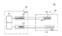
- the schematic diagram which shows the circuit structure of PM detection apparatus.
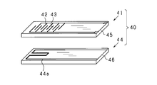
- the disassembled perspective view which shows the element part and heater of PM sensor.
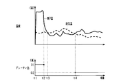
- the time chart which shows the change of element temperature and exhaust temperature.
- the present embodiment is embodied as an internal combustion engine system mounted on a vehicle.
- an internal combustion engine system 10 includes an internal combustion engine 11 that is a diesel engine.
- An intake passage 12 and an exhaust passage 13 are connected to the internal combustion engine 11.
- An exhaust gas purification device 14 is attached to the exhaust passage 13.
- the exhaust purification device 14 is configured to remove harmful components (nitrogen oxides, carbon compounds such as HC and CO, PM, etc. generated by unburned or incomplete combustion of fuel) from the exhaust discharged from the internal combustion engine 11.
- the exhaust purification device 14 is provided with a PM collection filter 15 (corresponding to a filter). Since the configuration of the exhaust purification device 14 is well known, the description thereof is omitted in this specification.
- the internal combustion engine system 10 is provided with a PM detection device 20 as a “particulate matter detection device”.
- the PM detection device 20 includes an ECU (Electric Control Unit) 30 and a PM sensor 40.
- the ECU 30 is configured to control the operation of the internal combustion engine 11 and its auxiliary machines and the operation as the PM detection device 20.
- the ECU 30 includes a microcomputer 31, a detection unit control circuit 32, and a heater control circuit 33.
- the microcomputer 31 includes a CPU (Central Processing Unit), a ROM (Read Only Memory), a RAM (Random Access Memory), a nonvolatile memory, and the like (not shown).
- the detection unit control circuit 32 is connected to an element unit 41 (including a pair of detection electrodes 42 and 43) provided in the PM sensor 40.
- the detection unit control circuit 32 is also connected to the microcomputer 31.
- the detection unit control circuit 32 includes a power supply circuit (not shown) that outputs a voltage applied between the detection electrodes 42 and 43 and a detection circuit (not shown) that detects the electrical characteristics of the element unit 41. Yes.
- the detection unit control circuit 32 causes the detection circuit to detect the electrical characteristics of the element unit 41 according to the adhesion state of the PM while a voltage is applied between the detection electrodes 42 and 43 by the power supply circuit.
- the detection circuit is configured to input the detected electrical characteristics to the microcomputer 31.
- the microcomputer 31 calculates the amount of PM adhering to the element unit 41 and, in turn, the amount of PM contained in the exhaust gas of the internal combustion engine 11 based on the detected electrical characteristics.
- the detection unit control circuit 32 and the microcomputer 31 constitute a detection unit.
- the heater control circuit 33 is connected to a heater 44 (including a heating wire 44a) provided in the PM sensor 40.
- the heater control circuit 33 is also connected to the microcomputer 31.
- the heater control circuit 33 includes a power supply circuit (not shown) and a drive circuit (not shown).
- the power supply circuit outputs a voltage applied to the heating wire 44a.
- the drive circuit changes the state in which the voltage of the power supply circuit is output to the heating wire 44a.
- the drive circuit changes a duty ratio that is a ratio of energizing the heating wire 44a in a predetermined period (pulse width modulation control).
- the microcomputer 31 controls the operation of the heater 44 according to the duty ratio commanded to the drive circuit.
- the heater control circuit 33 and the microcomputer 31 constitute a control unit.
- the PM sensor 40 includes the element unit 41 and the heater 44 as described above.
- the element portion 41 is mounted in the exhaust passage 13 so that the PM contained in the exhaust adheres when exposed to the exhaust.
- the element unit 41 includes an insulating substrate 45 and a pair of detection electrodes 42 and 43.
- the detection electrodes 42 and 43 are formed on the surface of the insulating substrate 45 by, for example, platinum. Although platinum has high heat resistance, it is known that oxidation and evaporation decrease under a high-temperature oxygen atmosphere. About the sample which comprised the detection electrodes 42 and 43 with the platinum electrode, the high temperature load test in air
- the insulating substrate 45 is made of ceramics or the like.
- the heater 44 is provided so as to burn and remove the PM adhering to the element unit 41 by generating heat by energization and heating the element unit 41.
- the heater 44 includes an insulating substrate 46 and a heating wire 44a.
- the heating wire 44a is formed on the surface of the insulating substrate 46 by, for example, platinum.
- the insulating substrate 46 is made of ceramics or the like.
- the PM sensor 40 is formed by stacking (bonding) the insulating substrate 45 and the insulating substrate 46 so that the element portion 41 and the heater 44 do not face each other.
- An element portion 41 is formed on the insulating substrate 45.
- a heater 44 is formed on the insulating substrate 46. Since the configuration of the PM sensor 40 is well known, further description is omitted in this specification.
- poisonous substances include iron oxide in the exhaust passage 13 and ash (hereinafter referred to as “ash”) remaining after burning the PM in the element portion 41.
- Ash is mainly composed of a metal salt (insulating substance) such as calcium sulfate or magnesium sulfate. Such components are derived from metallic elements such as calcium contained in the lubricating oil of the internal combustion engine 11 and sulfur contained in the fuel.
- the ECU 30 heats the element unit 41 with the heater 44 in a predetermined period excluding the collection period in which PM is adhered to the element unit 41.
- a thermophoretic force that moves the poisonous substance and PM away from the element portion 41 acts.
- Thermophoresis is a phenomenon in which particles are directed to the low temperature side when minute particles are present in a temperature gradient field. That is, when the temperature of the element unit 41 becomes higher than the temperature of the exhaust, a thermophoretic force in a direction away from the element unit 41 acts on the poisonous substance and PM.
- the detection electrodes 42 and 43 of the element unit 41 may be oxidized or reduced in evaporation as described above.
- the ECU 30 operates the heater 44 in a predetermined period excluding a period in which PM is adhered to the element unit 41.
- the predetermined control amount is set in advance so that the temperature of the element unit 41 is higher than the temperature of the exhaust gas and lower than a predetermined temperature (650 ° C.) at which the element unit 41 is thermally deteriorated.
- the duty ratio D commanded to the drive circuit of the heater control circuit 33 is set to a preset duty ratio D2 (predetermined duty ratio).
- the drive circuit of the heater control circuit 33 energizes the heating wire 44a of the heater 44 with a duty ratio D2.
- This duty ratio D2 is determined by adaptation for each vehicle on which the internal combustion engine 11 is mounted.
- the lower limit value that can be adopted as the duty ratio D2 is determined so that the temperature of the element unit 41 is higher than the temperature of the exhaust gas even in the operating state of the internal combustion engine 11 in which the temperature of the element unit 41 is most likely to decrease. .
- an operation state of the internal combustion engine 11 in which the temperature of the element portion 41 is most likely to decrease an operation state in which low-temperature exhaust flows at a high flow rate is assumed.
- the upper limit value that can be adopted as the duty ratio D2 is 650 ° C. (the temperature of the detection electrodes 42 and 43 of the element portion 41 causes thermal degradation even in the operating state of the internal combustion engine 11 in which the temperature of the element portion 41 is most likely to rise). It is determined to be lower than a predetermined temperature. As an operation state of the internal combustion engine 11 in which the temperature of the element portion 41 is most likely to rise, an operation state in which high-temperature exhaust flows at a high flow rate is assumed.
- the duty ratio D2 is set as a fixed value between the lower limit value and the upper limit value. When the heater 44 is operated at a preset duty ratio D2, the temperature of the element unit 41 changes according to the temperature of the exhaust.
- the duty ratio D2 is set in advance so that the difference between the temperature of the element portion 41 and the temperature of the exhaust gas is smaller than 100 ° C.
- the duty ratio D2 when the temperature of the exhaust gas temporarily rises or when the element unit 41 is rapidly cooled, the temperature of the element unit 41 may temporarily become lower than the temperature of the exhaust gas. In this case, the thermophoretic force cannot be applied to the poisonous substance or PM in the direction away from the element unit 41.
- the duty ratio D2 in order to completely prevent such a state, the duty ratio D2 must be set excessively high, and the temperature of the element portion 41 is likely to be higher than 650 ° C.
- the duty ratio D2 is set in advance so that the temperature of the element portion 41 becomes higher than the temperature of the exhaust gas in a period exceeding 80% in a predetermined period. This predetermined period is a period during which the heater 44 is operated at the duty ratio D2.
- the internal combustion engine 11 was operated in a steady state in the maximum rotation speed range. Then, a test was performed under a condition corresponding to 300,000 km of actual traveling of the vehicle by providing a period in which the temperature of the exhaust becomes higher than the temperature of the element unit 41 by stopping the heater 44. As a result, when the period during which the exhaust temperature is higher than the temperature of the element unit 41 is 80% or more with respect to the predetermined period, the sensitivity of the PM sensor 40 does not decrease, and 75%, 70%, 65% In this case, the sensitivity was reduced by 15%, 21% and 30%, respectively.
- a PM collection filter 15 is provided upstream of the element portion 41 in the exhaust passage 13 of the internal combustion engine 11. During the period in which the PM collected by the PM collection filter 15 is combusted, high-temperature exhaust gas flows to the element unit 41 and the temperature of the element unit 41 is likely to rise rapidly. Further, even during the rapid acceleration period of the internal combustion engine 11, the high-temperature exhaust gas flows to the element part 41 and the temperature of the element part 41 is likely to rise rapidly. Even in such a case, if the temperature of the element unit 41 is to be made higher than the temperature of the exhaust, the duty ratio D2 must be set excessively high. In such a case, there is a high possibility that the temperature of the element unit 41 is higher than 650 ° C. In this regard, the duty ratio D2 is such that the temperature of the exhaust gas can be higher than the temperature of the element unit 41 during the period in which the PM collected by the PM collection filter 15 is burned or during the rapid acceleration period of the internal combustion engine 11. Is set in advance.
- the duty ratio D2 is set so that the temperature of the exhaust gas becomes higher than the temperature of the element portion 41 in the period of 80% with respect to the period (predetermined period) in which the heater 44 is operated at the duty ratio D2. Is set in advance. In other words, the duty ratio D2 is set in advance so that the temperature of the exhaust gas becomes lower than the temperature of the element unit 41 in a period of 10% with respect to the predetermined period. At this time, the temperature of the element portion 41 is not higher than the exhaust temperature by 100 ° C. or more, and is 600 ° C. at the maximum.
- the PM amount is detected once by the PM detection device 20 from the start to the end of the operation of the internal combustion engine 11. Therefore, a predetermined period in which the element unit 41 is heated with the duty ratio D2 by the heater 44 is included in the period after the amount of PM is detected. Specifically, a period from the end of detection of the amount of PM to the stop of operation of the internal combustion engine 11 is set as the predetermined period.
- FIG. 4 is a time chart showing an aspect in which the temperature of the element unit 41 and the temperature of the exhaust gas change in the PM amount detection by the PM detection device 20.
- the ECU 30 starts control for burning PM adhering to the element unit 41 prior to detection of the PM amount.
- the duty ratio D commanded to the drive circuit of the heater control circuit 33 is set to a preset duty ratio D1 higher than the duty ratio D2.
- the drive circuit of the heater control circuit 33 energizes the heating wire 44a of the heater 44 with a duty ratio D1.
- the duty ratio D1 is a duty ratio that raises the temperature of the element portion 41 to a temperature at which PM can be combusted (for example, 600 ° C.), and is determined by adaptation for each vehicle on which the internal combustion engine 11 is mounted. Thereby, as shown by a solid line, the temperature of the element part 41 rises to approximately 600 ° C.
- Times t1 to t2 are a combustion period (PM sensor regeneration mode) in which PM adhering to the element unit 41 is combusted.
- the ECU 30 ends the control for burning the PM adhering to the element unit 41.
- the microcomputer 31 sets the duty ratio D commanded to the drive circuit of the heater control circuit 33 to 0%. Thereby, the temperature of the element part 41 falls.
- Time t2 to t3 is a cooling period (PM sensor cooling mode) in which the element unit 41 is cooled.
- the ECU 30 starts control for attaching PM to the element unit 41.
- the detection unit control circuit 32 may charge the PM passing through the vicinity of the detection electrodes 42 and 43 by applying a voltage between the detection electrodes 42 and 43 by the power supply circuit (electrostatic collection).
- the power supply circuit electrostatic collection
- adhesion of PM to the element unit 41 is promoted.
- the temperature of the exhaust gas varies according to the operating state of the internal combustion engine 11, and accordingly, the temperature of the element unit 41 varies at a temperature slightly lower than the temperature of the exhaust gas.
- Times t3 to t4 are a collection period (PM collection mode) in which PM is adhered to the element unit 41.
- the ECU 30 detects the amount of PM attached to the element unit 41.
- the detection unit control circuit 32 causes the detection circuit to detect a current value flowing between the detection electrodes 42 and 43 in a state where a voltage is applied between the detection electrodes 42 and 43 by the power supply circuit.
- the detection circuit inputs the detected current value to the microcomputer 31.
- the microcomputer 31 calculates the amount of PM attached to the element unit 41 based on the input current value.
- the microcomputer 31 includes a map that defines the relationship between the current value and the amount of PM during the PM collection period (time t3 to t4). This map can be set in advance based on experiments or the like.
- the microcomputer 31 refers to the map to calculate the amount of PM corresponding to the input current value, and thus calculates the amount of PM contained in the exhaust gas of the internal combustion engine 11.
- the ECU 30 executes control to suppress poisonous substances and PM from adhering to the element unit 41.
- the duty ratio D commanded to the drive circuit of the heater control circuit 33 is the duty ratio D2.
- the drive circuit of the heater control circuit 33 energizes the heating wire 44a of the heater 44 with a duty ratio D2.
- the temperature of the element part 41 shown as a continuous line is maintained in a slightly higher state than the temperature of the exhaust gas shown as a broken line.
- the temperature of the exhaust varies depending on the operating state of the internal combustion engine 11. For this reason, the temperature of the element part 41 fluctuates at a temperature slightly higher than the temperature of the exhaust gas according to the temperature of the exhaust gas.
- the embodiment described in detail above has the following advantages.
- the microcomputer 31 and the heater control circuit 33 (ECU 30) have a predetermined duty ratio D2 (predetermined control amount) in a predetermined period excluding the collection period (time t3 to t4) during which PM is adhered to the element unit 41.
- the heater 44 is operated.
- the heater 44 is operated for a predetermined period excluding the collection period during which PM is adhered to the element unit 41, so that it does not hinder the adhesion of PM to the element unit 41.
- the duty ratio D2 is set in advance so that the temperature of the element unit 41 is lower than 650 ° C. (predetermined temperature) at which the element unit 41 is thermally deteriorated. For this reason, even if the heater 44 is operated at the duty ratio D2, the thermal stress applied to the element portion 41 can be suppressed. Further, the duty ratio D2 is set in advance so that the temperature of the element unit 41 is higher than the temperature of the exhaust gas in a period of 10% with respect to the predetermined period. When fine particles are present in a field with a temperature gradient, the particles are subjected to thermophoretic force toward the low temperature side.
- thermophoretic force can be applied to poisonous substances (ash, iron oxide, etc.) and PM in a direction away from the element part 41, and deposition of poisonous substances on the element part 41 can be suppressed.
- the heater 44 is operated with a preset duty ratio D2, it is not necessary to detect the temperature of the element unit 41 and adjust the control amount.
- the duty ratio D2 is set in advance so that the difference between the temperature of the element unit 41 and the temperature of the exhaust is smaller than 100 ° C.
- the temperature of exhaust gas from a diesel engine rises up to 500 ° C. Therefore, even if the temperature of the exhaust gas fluctuates, the temperature of the element portion 41 can be suppressed from becoming higher than 600 ° C.
- the duty ratio D2 is set in advance so that the temperature of the element portion 41 becomes higher than the temperature of the exhaust gas in a period exceeding 80% in the predetermined period.
- This predetermined period is a period during which the heater 44 is operated at the duty ratio D2. Therefore, suppression of thermal stress applied to the element portion 41 and suppression of poisonous substance deposition on the element portion 41 can be balanced appropriately.
- the duty ratio D2 is set so that the temperature of the exhaust gas can be higher than the temperature of the element unit 41 during the period in which the PM collected by the PM collection filter 15 is burned or during the rapid acceleration period of the internal combustion engine 11. It is set in advance. Therefore, in such a case, it can be exceptionally allowed that the temperature of the element part 41 temporarily becomes lower than the temperature of the exhaust. Further, the duty ratio D2 can be prevented from being set too high.
- the predetermined period during which the heater 44 is operated at the duty ratio D2 is included in the period after the amount of PM is detected by the microcomputer 31 and the detection unit control circuit 32 (ECU 30). For this reason, it is possible to prevent the PM from adhering to the element portion 41 until the amount of PM is detected. Furthermore, after the amount of PM is detected, the deposition of poisonous substances on the element unit 41 can be suppressed. In particular, since the period from the end of detection of the amount of PM to the stop of operation of the internal combustion engine 11 is set as the predetermined period, the amount of poisonous substances adhering to the element unit 41 can be minimized.
- the temperature of the element portion 41 is made higher than the temperature of the exhaust.
- the temperature of the element unit 41 changes according to the temperature of the exhaust, the temperature of the element unit 41 can be lowered when the temperature of the exhaust is low. Therefore, compared to a configuration in which the temperature of the element unit 41 is maintained at a constant temperature higher than the temperature of the exhaust, it is possible to suppress the element unit 41 from being heated more than necessary, and thermal stress applied to the element unit 41 Can be suppressed.
- the predetermined period during which the heater 44 is operated at the duty ratio D2 is the period after the amount of PM is detected each time. It may be included.
- a water repellent period for repelling water adhering to the element part 41 due to the Leidenfrost phenomenon is provided before the combustion period (time t1 to t2) in which PM adhering to the element part 41 is burned. Also good.
- the heater 44 may be energized with a duty ratio D2 during the water repellent period (predetermined period). Thereby, adhesion of poisonous substances to the element portion 41 can be suppressed during the water repellent period.
- the operation period of the internal combustion engine 11 in which the state in which PM adheres to the element unit 41 becomes abnormal may be set as a predetermined period excluding the collection period in which PM is adhered to the element unit 41. And if the period when the state which PM adheres becomes abnormal is complete
- the heater 44 is operated at a duty ratio D2 in a predetermined period. Therefore, a thermophoretic force can be applied to the PM in addition to the poisoning substance in a direction away from the element unit 41, and PM deposition on the element unit 41 can be suppressed. As a result, PM can be attached to the element unit 41 in an appropriate period, and the accuracy of detecting the amount of PM can be improved. As a period in which the state in which PM adheres to the element unit 41 becomes abnormal, it is possible to employ the time when the internal combustion engine 11 is started, the time of acceleration / deceleration, or the like.
- the temperature of the element unit 41 may temporarily become higher than the temperature at which PM starts combustion (for example, 500 ° C.). In this case, there is a possibility that PM adhering to the element portion 41 may temporarily burn.
- the duty ratio D2 in order to completely prevent such a state, the duty ratio D2 must be set excessively low, and there is a high possibility that the temperature of the element portion 41 becomes lower than the temperature of the exhaust.
- the duty ratio D2 is set in advance so that the temperature of the element unit 41 becomes lower than the temperature at which PM starts combustion in a period exceeding 80% in a predetermined period. Good.
- This predetermined period is a period during which the heater 44 is operated at the duty ratio D2. According to such a configuration, it is possible to suppress abnormal accumulation of PM on the element unit 41 while suppressing PM adhering to the element unit 41 from burning before detection. In addition, even if the temperature of the element part 41 becomes temporarily higher than the temperature at which PM starts combustion, the PM does not stop burning immediately.
- the duty ratio D2 is determined so that the temperature of the element unit 41 is combusted during the period in which the PM collected by the PM collection filter 15 is combusted or during the rapid acceleration period of the internal combustion engine 11.
- the temperature is extremely low in a cold district or the like.
- the duty ratio D2 is not limited to a fixed value, and may be variable between a lower limit value and an upper limit value.
- the configuration for operating the heater 44 with a predetermined control amount set in advance is not limited to the configuration in which the heater 44 is energized with the duty ratio D2.
- a configuration in which the heater 44 is energized with a predetermined current value set in advance, a configuration in which the heater 44 is energized with a predetermined voltage value set in advance, or the like may be employed.
- the heater 44 may be operated with a predetermined control amount set in advance so that the temperature of the element unit 41 is higher than the temperature of the exhaust gas and lower than a predetermined temperature at which the element unit 41 is thermally deteriorated.
- the ECU 30 controls the heater 44 with a control amount that lowers the temperature of the element unit 41 rather than operating the heater 44 with a predetermined control amount when the temperature of the element unit 41 is higher than the temperature at which PM starts combustion. It is also possible to adopt a configuration that operates.
- the temperature of the element unit 41 can be estimated based on the operating state of the internal combustion engine 11, for example.
- As a control amount for decreasing the temperature of the element unit 41 for example, a control amount obtained by reducing a predetermined control amount by a certain amount can be employed. According to such a configuration, the PM adhering to the element unit 41 can be prevented from temporarily burning.
- a temperature sensor for detecting the temperature of the element unit 41 is provided in the internal combustion engine.
- the ECU 30 can employ the following configuration. That is, the ECU 30 can employ a configuration in which the heater 44 is operated with a control amount that lowers the temperature of the element unit 41, rather than the heater 44 is operated with a predetermined control amount. According to such a structure, it can suppress reliably that PM adhering to the element part 41 combusts temporarily.
- a thermistor or the like that detects the temperature of the element unit 41 can be employed. When the heating wire 44a of the heater 44 is energized to generate heat, the resistance value of the heating wire 44a changes.
- the temperature of the heating wire 44a corresponds to a temperature sensor.
- a predetermined control amount can also be adjusted so that the temperature of the element part 41 may become target temperature.
- a configuration in which the heater 44 is provided separately from the PM sensor 40 may be employed.
- the PM detection device may be constituted by a PM sensor module including the PM sensor 40 and a control unit of the PM sensor 40.
- an internal combustion engine that uses fuel such as gasoline, alcohol, natural gas, etc.
- it can be embodied as a device that detects PM contained in exhaust gas.
- the temperature of exhaust gas from a gasoline engine rises to a maximum of 800 ° C.
- the temperature of the exhaust gas flowing to the element unit 41 may be allowed to temporarily exceed 500 ° C. in a limited operation state of the gasoline engine (internal combustion engine).
Landscapes
- Engineering & Computer Science (AREA)
- Chemical & Material Sciences (AREA)
- Combustion & Propulsion (AREA)
- Mechanical Engineering (AREA)
- General Engineering & Computer Science (AREA)
- Pathology (AREA)
- General Health & Medical Sciences (AREA)
- Physics & Mathematics (AREA)
- Health & Medical Sciences (AREA)
- Life Sciences & Earth Sciences (AREA)
- Analytical Chemistry (AREA)
- Biochemistry (AREA)
- Immunology (AREA)
- General Physics & Mathematics (AREA)
- Dispersion Chemistry (AREA)
- Chemical Kinetics & Catalysis (AREA)
- Electrochemistry (AREA)
- Processes For Solid Components From Exhaust (AREA)
- Exhaust Gas After Treatment (AREA)
- Combined Controls Of Internal Combustion Engines (AREA)
Abstract
内燃機関の排気中に含まれる粒子状物質を付着させる素子部41と、素子部41を加熱するヒータ44と、素子部41の電気的特性に基づいて粒子状物質の量を検出する検出部31,32と、ヒータ44の動作を制御する制御部31,33と、を備える粒子状物質検出装置20であって、制御部31,33は、素子部41に粒子状物質を付着させる期間を除く所定期間において、素子部41の温度が排気の温度よりも高く素子部41が熱劣化する所定温度よりも低くなるように予め設定された所定制御量で、ヒータ44を動作させる。
Description
本発明は、内燃機関の排気中に含まれる粒子状物質を検出する装置に関する。
従来、粒子状物質センサには、排気中の粒子状物質(Particulate Matter、以下「PM」という)を検出した後に、粒子状物質センサの素子部に堆積したPMを燃焼させて除去するものがある(特許文献1参照)。この時、粒子状物質センサの素子部はPMを燃焼させる所定の温度域に制御されている。特許文献1に記載の粒子状物質センサは、PMを燃焼させて除去してから、内燃機関が停止するまでの間、素子部を上記所定の温度域に維持している。したがって、PMを燃焼させて除去した後に、素子部にPMが堆積することを抑制することができる。このため、粒子状物質センサは、次回の内燃機関の始動時に、PMの燃焼を行うことなくPMの検出を開始することができる。
しかしながら、特許文献1に記載の粒子状物質センサは、PMの検出後にPMを燃焼させる所定の温度域に維持する。このため、粒子状物質センサの素子部に加わる熱ストレスが増加し、粒子状物質センサの耐久性が低下するおそれがある。
また、粒子状物質センサの素子部に被毒物質が堆積することにより、粒子状物質センサの機能が低下するという問題がある。
本発明は、こうした実情に鑑みてなされたものであり、その主たる目的は、粒子状物質検出装置の素子部に加わる熱ストレスの抑制と、素子部への被毒物質の堆積抑制とを両立することのできる粒子状物質検出装置を提供することにある。
以下、上記課題を解決するための手段、及びその作用効果について記載する。
本発明は、素子部と、ヒータと、検出部と、制御部と、を備える粒子状物質検出装置である。上記素子部は、内燃機関の排気中に含まれる粒子状物質を付着させる。上記ヒータは前記素子部を加熱する。上記検出部は前記素子部の電気的特性に基づいて前記粒子状物質の量を検出する。上記制御部は前記ヒータの動作を制御する。前記制御部は、所定期間において、予め設定された所定制御量で、前記ヒータを動作させることを特徴とする。上記所定期間は前記素子部に前記粒子状物質を付着させる期間を除く。上記所定制御量は、前記素子部の温度が前記排気の温度よりも高く前記素子部が熱劣化する所定温度よりも低くなるように予め設定されている。
上記構成によれば、内燃機関の排気中に含まれる粒子状物質(PM)が、素子部に付着させられる。PMはある程度の導電性を有しているため、素子部にPMが付着すると素子部の電気的特性が変化する。そこで、検出部により、素子部の電気的特性に基づいて、粒子状物質の量が検出される。
そして、制御部により、上記所定期間において、予め設定された所定制御量で、素子部を加熱するヒータが動作させられる。ヒータが動作させられるのは、素子部に粒子状物質を付着させる期間を除く所定期間であるため、素子部に粒子状物質を付着させることに支障を来さない。
ここで、上記所定制御量は、素子部が熱劣化する所定温度よりも素子部の温度が低くなるように予め設定されている。このため、所定制御量でヒータを動作させても、素子部に加わる熱ストレスを抑制することができる。さらに、上記所定制御量は、排気の温度よりも素子部の温度が高くなるように予め設定されている。温度勾配のある場に微小な粒子が存在する場合、粒子は低温側に向かう熱泳動力を受ける。このため、素子部から離れる向きに被毒物質やPMに熱泳動力を作用させることができ、素子部への被毒物質の堆積を抑制することができる。しかも、ヒータは予め設定された所定制御量で動作させられるため、素子部の温度を検出して制御量を調節する必要がない。
以下、一実施形態について、図面を参照しつつ説明する。本実施形態は、車両に搭載される内燃機関システムとして具体化している。
<実施形態の装置構成>
図1を参照すると、内燃機関システム10においては、ディーゼル機関である内燃機関11が設けられている。内燃機関11には、吸気通路12と排気通路13とが接続されている。排気通路13には、排気浄化装置14が装着されている。排気浄化装置14は、内燃機関11から排出された排気から有害成分(窒素酸化物、燃料の未燃あるいは不完全燃焼によって生じたHCやCO等の炭素化合物、PM等)を除去するように構成されている。特に、本実施形態においては、排気浄化装置14には、PM捕集フィルタ15(フィルタに相当)が設けられている。かかる排気浄化装置14の構成については周知であるので、本明細書においては説明を省略する。
図1を参照すると、内燃機関システム10においては、ディーゼル機関である内燃機関11が設けられている。内燃機関11には、吸気通路12と排気通路13とが接続されている。排気通路13には、排気浄化装置14が装着されている。排気浄化装置14は、内燃機関11から排出された排気から有害成分(窒素酸化物、燃料の未燃あるいは不完全燃焼によって生じたHCやCO等の炭素化合物、PM等)を除去するように構成されている。特に、本実施形態においては、排気浄化装置14には、PM捕集フィルタ15(フィルタに相当)が設けられている。かかる排気浄化装置14の構成については周知であるので、本明細書においては説明を省略する。
また、内燃機関システム10には、「粒子状物質検出装置」としてのPM検出装置20が設けられている。このPM検出装置20は、ECU(Electric Control Unit)30及びPMセンサ40を備えている。ECU30は、内燃機関11及びその補機類の動作を制御するとともに、PM検出装置20としての動作を制御するように構成されている。
図2を参照すると、ECU30は、マイクロコンピュータ31と、検出部制御回路32と、ヒータ制御回路33と、を備えている。マイクロコンピュータ31は、図示しないCPU(Central Processing Unit)、ROM(Read Only Memory)、RAM(Random Access Memory)、不揮発性メモリ等を備えている。
検出部制御回路32は、PMセンサ40に設けられた素子部41(一対の検出電極42,43を含む)に接続されている。また、検出部制御回路32は、マイクロコンピュータ31にも接続されている。この検出部制御回路32は、検出電極42,43間に印加される電圧を出力する電源回路(図示略)と、素子部41の電気的特性を検出する検出回路(図示略)とを備えている。検出部制御回路32は、電源回路により検出電極42,43間に電圧を印加させた状態で、検出回路によりPMの付着状態に応じた素子部41の電気的特性を検出させる。検出回路は、検出した電気的特性をマイクロコンピュータ31に入力するようになっている。電気的特性としては、検出電極42,43間に流れる電流や、検出電極42,43間の抵抗等を採用することができる。マイクロコンピュータ31は、検出された電気的特性に基づいて、素子部41に付着したPMの量、ひいては内燃機関11の排気中に含まれるPMの量を算出する。なお、検出部制御回路32及びマイクロコンピュータ31により、検出部が構成されている。
ヒータ制御回路33は、PMセンサ40に設けられたヒータ44(電熱線44aを含む)に接続されている。また、ヒータ制御回路33は、マイクロコンピュータ31にも接続されている。このヒータ制御回路33は、電源回路(図示略)と駆動回路(図示略)とを備えている。電源回路は、電熱線44aに印加される電圧を出力する。駆動回路は、この電源回路の電圧が電熱線44aに出力される状態を変更する。駆動回路は、所定周期のうち電熱線44aに通電する比率であるデューティ比を変更する(パルス幅変調制御)。マイクロコンピュータ31は、駆動回路に指令するデューティ比により、ヒータ44の動作を制御する。なお、ヒータ制御回路33及びマイクロコンピュータ31により、制御部が構成されている。
図2及び図3を参照しつつ、PMセンサ40の具体的な構成について説明する。PMセンサ40は、上述したように素子部41及びヒータ44を備えている。
素子部41は、排気中に暴露されることで当該排気中に含まれるPMが付着するように、排気通路13に装着されている。素子部41は、絶縁基板45と、一対の検出電極42,43とを備えている。検出電極42,43は、絶縁基板45の表面に、例えば白金により形成されている。白金は、高い耐熱性を有するが、高温の酸素雰囲気下では酸化及び蒸発減少することが知られている。検出電極42,43を白金電極で構成したサンプルについて、大気中での高温負荷試験を720時間実施した。結果、650℃(所定温度に相当)以上で電極の蒸発減少が確認され、600℃では確認されなかった。絶縁基板45は、セラミックス等により形成されている。
ヒータ44は、通電により発熱して素子部41を加熱することで、素子部41に付着したPMを燃焼させて除去するように設けられている。ヒータ44は、絶縁基板46と、電熱線44aとを備えている。電熱線44aは、絶縁基板46の表面に、例えば白金により形成されている。絶縁基板46は、セラミックス等により形成されている。
そして、絶縁基板45と、絶縁基板46とが、素子部41とヒータ44とが互いに向き合わないように積層(接合)されることで、PMセンサ40が形成されている。絶縁基板45には素子部41が形成されている。絶縁基板46には、ヒータ44が形成されている。なお、かかるPMセンサ40の構成については周知であるので、本明細書においてはこれ以上の説明を省略する。
ところで、素子部41に被毒物質が堆積すると、PMセンサ40の機能が低下する。被毒物質としては、排気通路13中の酸化鉄や、素子部41のPMを燃焼させた後に残留する灰分(以下「アッシュ」という)がある。アッシュは、硫酸カルシウムや硫酸マグネシウム等の金属塩(絶縁性物質)を主たる成分とするものである。かかる成分は、内燃機関11の潤滑油等に含まれるカルシウム等の金属元素、燃料に含まれる硫黄等に由来するものである。そして、被毒物質の堆積量が増加すると、素子部41の電気抵抗が上昇したり、素子部41にPMが付着しにくくなったりする。
そこで、本実施形態では、ECU30は、素子部41にPMを付着させる捕集期間を除く所定期間において、素子部41をヒータ44により加熱させる。これは、素子部41から被毒物質やPMを遠ざける熱泳動力が作用するようにするためである。熱泳動とは、温度勾配のある場に微小な粒子が存在する場合に、粒子が低温側に向かう現象である。すなわち、素子部41の温度が排気の温度よりも高くなれば、被毒物質やPMに、素子部41から遠ざかる方向の熱泳動力が作用する。ただし、素子部41の温度が高くなり過ぎると、上述したように素子部41の検出電極42,43が、酸化したり蒸発減少したりするおそれがある。
この点、本実施形態では、ECU30は、素子部41にPMを付着させる期間を除く所定期間において、ヒータ44を動作させた。この時、所定制御量は素子部41の温度が排気の温度よりも高く素子部41が熱劣化する所定温度(650℃)よりも低くなるように予め設定されている。具体的には、マイクロコンピュータ31において、ヒータ制御回路33の駆動回路に指令するデューティ比Dを、予め設定されたデューティ比D2(所定デューティ比)とする。ヒータ制御回路33の駆動回路は、デューティ比D2でヒータ44の電熱線44aに通電する。このデューティ比D2は、内燃機関11を搭載した車両毎の適合により決定されている。
デューティ比D2として採用可能な下限値は、素子部41の温度が最も下がり易い内燃機関11の運転状態であっても、素子部41の温度が排気の温度よりも高くなるように決定されている。素子部41の温度が最も下がり易い内燃機関11の運転状態として、低温の排気が高流速で流れる運転状態を想定している。
デューティ比D2として採用可能な上限値は、素子部41の温度が最も上がり易い内燃機関11の運転状態であっても、素子部41の検出電極42,43の温度が熱劣化の生じる650℃(所定温度)よりも低くなるように決定されている。素子部41の温度が最も上がり易い内燃機関11の運転状態として、高温の排気が高流速で流れる運転状態を想定している。そして、デューティ比D2は、上記下限値と上記上限値との間の固定値として設定されている。予め設定されたデューティ比D2でヒータ44を動作させる場合、素子部41の温度は排気の温度に応じて変化する。ここで、デューティ比D2は、素子部41の温度と排気の温度との差が100℃よりも小さくなるように予め設定されている。
また、排気の温度が一時的に急上昇する場合や、素子部41が急冷される場合は、素子部41の温度が排気の温度よりも一時的に低くなることが起こり得る。この場合、素子部41から離れる向きに、被毒物質やPMに熱泳動力を作用させることができなくなる。しかしながら、このような状態を完全に防ごうとすると、デューティ比D2を過剰に高く設定せざるを得ず、素子部41の温度が650℃よりも高くなる可能性が高くなる。この点、デューティ比D2は、所定期間において、80%を超える期間で素子部41の温度が排気の温度よりも高くなるように予め設定されている。この所定期間は、デューティ比D2でヒータ44を動作させる期間である。内燃機関11を最高回転速度域で定常運転させた。そして、ヒータ44を停止させることで排気の温度が素子部41の温度よりも高くなる期間を設けて、車両の実走行の30万kmに相当する条件で試験を行った。その結果、この所定期間に対して、排気の温度が素子部41の温度よりも高くなる期間が、80%以上の場合はPMセンサ40の感度低下は生じず、75%,70%,65%の場合は、それぞれ15%,21%,30%の感度低下が生じた。
さらに、内燃機関11の排気通路13において素子部41よりも上流には、PM捕集フィルタ15が設けられている。PM捕集フィルタ15により捕集されたPMを燃焼させている期間は、高温の排気が素子部41へ流れて素子部41の温度が急上昇し易い。また、内燃機関11の急加速期間においても、高温の排気が素子部41へ流れて素子部41の温度が急上昇し易い。このような場合にも、素子部41の温度を排気の温度よりも高くしようとすると、デューティ比D2を過剰に高く設定せざるを得ない。そうした場合、素子部41の温度が650℃よりも高くなる可能性が高くなる。この点、デューティ比D2は、PM捕集フィルタ15により捕集されたPMを燃焼させている期間、又は内燃機関11の急加速期間において、排気の温度が素子部41の温度よりも高くなり得るように予め設定されている。
以上により、本実施形態では、デューティ比D2でヒータ44を動作させる期間(所定期間)に対して、80%の期間で排気の温度が素子部41の温度よりも高くなるように、デューティ比D2を予め設定している。換言すれば、上記所定期間に対して、10%の期間で排気の温度が素子部41の温度よりも低くなるように、デューティ比D2を予め設定している。このとき、素子部41の温度は、排気の温度よりも100℃以上高くならず、最高で600℃となっている。
また、本実施形態では、内燃機関11の運転開始から運転終了までに、PM検出装置20により、PMの量の検出を1回行う。そこで、ヒータ44によりデューティ比D2で素子部41を加熱する所定期間を、PMの量を検出した後の期間に含ませている。具体的には、所定期間として、PMの量の検出終了から内燃機関11の運転停止までの期間を設定している。
図4は、PM検出装置20によるPM量検出において、素子部41の温度及び排気の温度が変化する態様を示すタイムチャートである。
時刻t1において、ECU30は、PM量の検出に先立って、素子部41に付着しているPMを燃焼させる制御を開始する。具体的には、マイクロコンピュータ31において、ヒータ制御回路33の駆動回路に指令するデューティ比Dを、上記デューティ比D2よりも高い予め設定されたデューティ比D1とする。ヒータ制御回路33の駆動回路は、デューティ比D1でヒータ44の電熱線44aに通電する。このデューティ比D1は、PMを燃焼させることの可能な温度(例えば600℃)まで素子部41の温度を上昇させるデューティ比であり、内燃機関11を搭載した車両毎の適合により決定されている。これにより、実線で示すように、素子部41の温度が略600℃まで上昇する。破線で示すように、排気の温度は、内燃機関11の運転状態に応じて変動する。このため、素子部41の温度は、排気の温度に応じて600℃付近で変動する。時刻t1~t2は、素子部41に付着したPMを燃焼させる燃焼期間(PMセンサ再生モード)である。
時刻t2において、ECU30は、素子部41に付着しているPMを燃焼させる制御を終了する。具体的には、マイクロコンピュータ31は、ヒータ制御回路33の駆動回路に指令するデューティ比Dを0%とする。これにより、素子部41の温度が低下する。時刻t2~t3は、素子部41を冷却する冷却期間(PMセンサ冷却モード)である。
時刻t3において、ECU30は、素子部41にPMを付着させる制御を開始する。このとき、検出部制御回路32は、電源回路により検出電極42,43間に電圧を印加させて、検出電極42,43の近傍を通過するPMを帯電させてもよい(静電捕集)。PMが帯電することにより、素子部41へのPMの付着が促進される。排気の温度が内燃機関11の運転状態に応じて変動し、それに伴って素子部41の温度が排気の温度よりもやや低い温度で変動する。時刻t3~t4は、素子部41にPMを付着させる捕集期間(PM捕集モード)である。
時刻t4において、ECU30は、素子部41に付着したPMの量を検出する。具体的には、検出部制御回路32は、電源回路により検出電極42,43間に電圧を印加させた状態で、検出回路により検出電極42,43間に流れる電流値を検出させる。検出回路は、検出した電流値をマイクロコンピュータ31に入力する。マイクロコンピュータ31は、入力された電流値に基づいて、素子部41に付着したPMの量を算出する。例えば、マイクロコンピュータ31は、PMの捕集期間(時刻t3~t4)における上記電流値とPMの量との関係を規定するマップを備えている。このマップは、予め実験等に基づいて設定しておくことができる。そして、マイクロコンピュータ31は、マップを参照して、入力された電流値に対応するPMの量を算出し、ひいては内燃機関11の排気中に含まれるPMの量を算出する。
時刻t4以後、ECU30は、素子部41に被毒物質やPMが付着することを抑制する制御を実行する。具体的には、マイクロコンピュータ31において、ヒータ制御回路33の駆動回路に指令するデューティ比Dを、上記デューティ比D2とする。ヒータ制御回路33の駆動回路は、デューティ比D2でヒータ44の電熱線44aに通電する。これにより、実線で示す素子部41の温度は、破線で示す排気の温度よりもやや高い状態に維持される。排気の温度は、内燃機関11の運転状態に応じて変動する。このため、素子部41の温度は、排気の温度に応じて排気の温度よりもやや高い温度で変動する。時刻t4以後は、素子部41に被毒物質やPMが付着することを抑制する抑制期間(付着抑制モード)である。
以上詳述した本実施形態は、以下の利点を有する。
・マイクロコンピュータ31及びヒータ制御回路33(ECU30)により、素子部41にPMを付着させる捕集期間(時刻t3~t4)を除く所定期間において、予め設定されたデューティ比D2(所定制御量)でヒータ44が動作させられる。ヒータ44が動作させられるのは、素子部41にPMを付着させる捕集期間を除く所定期間であるため、素子部41にPMを付着させることに支障を来さない。
・マイクロコンピュータ31及びヒータ制御回路33(ECU30)により、素子部41にPMを付着させる捕集期間(時刻t3~t4)を除く所定期間において、予め設定されたデューティ比D2(所定制御量)でヒータ44が動作させられる。ヒータ44が動作させられるのは、素子部41にPMを付着させる捕集期間を除く所定期間であるため、素子部41にPMを付着させることに支障を来さない。
・上記デューティ比D2は、素子部41が熱劣化する650℃(所定温度)よりも素子部41の温度が低くなるように予め設定されている。このため、デューティ比D2でヒータ44を動作させても、素子部41に加わる熱ストレスを抑制することができる。さらに、上記デューティ比D2は、上記所定期間に対して、10%の期間で排気の温度よりも素子部41の温度が高くなるように予め設定されている。温度勾配のある場に微小な粒子が存在する場合、粒子は低温側に向かう熱泳動力を受ける。このため、素子部41から離れる向きに被毒物質(アッシュ、酸化鉄等)やPMに熱泳動力を作用させることができ、素子部41への被毒物質の堆積を抑制することができる。しかも、ヒータ44は予め設定されたデューティ比D2で動作させられるため、素子部41の温度を検出して制御量を調節する必要がない。
・デューティ比D2は、素子部41の温度と排気の温度との差が100℃よりも小さくなるように予め設定されている。一般に、ディーゼル機関の排気の温度は、最高500℃まで上昇する。したがって、排気の温度が変動したとしても、素子部41の温度が600℃よりも高くなることを抑制することができる。
・デューティ比D2は、上記所定期間において、80%を超える期間で素子部41の温度が排気の温度よりも高くなるように予め設定されている。この所定期間は、デューティ比D2でヒータ44を動作させる期間である。したがって、素子部41に加わる熱ストレスの抑制と、素子部41への被毒物質の堆積抑制とを、適度に均衡させることができる。
・デューティ比D2は、PM捕集フィルタ15により捕集されたPMを燃焼させている期間、又は内燃機関11の急加速期間において、排気の温度が素子部41の温度よりも高くなり得るように予め設定されている。したがって、このような場合は、例外的に素子部41の温度が排気の温度よりも一時的に低くなることを許容することができる。また、デューティ比D2が過剰に高く設定されないようにすることができる。
・デューティ比D2でヒータ44を動作させる所定期間は、マイクロコンピュータ31及び検出部制御回路32(ECU30)によりPMの量を検出した後の期間に含まれている。このため、PMの量を検出するまでは、素子部41にPMを付着させることに支障を来さないようにすることができる。さらに、PMの量を検出した後は、素子部41への被毒物質の堆積を抑制することができる。特に、所定期間として、PMの量の検出終了から内燃機関11の運転停止までの期間を設定しているため、素子部41への被毒物質の付着量を最少にすることができる。
・デューティ比D2でヒータ44を動作させることにより、素子部41の温度を排気の温度よりも高くしている。このとき、素子部41の温度は排気の温度に応じて変化するため、排気の温度が低い場合に素子部41の温度を低くすることができる。したがって、素子部41の温度を排気の温度よりも高い一定温度に維持する構成と比較して、素子部41が必要以上に加熱されることを抑制することができ、素子部41に加わる熱ストレスを抑制することができる。
なお、上記実施形態を、以下のように変更して実施することもできる。
・内燃機関11の運転開始から運転終了までに、PMの量の検出を複数回行う場合は、デューティ比D2でヒータ44を動作させる所定期間が、各回においてPMの量を検出した後の期間に含まれるようにしてもよい。
・素子部41に付着したPMを燃焼させる燃焼期間(時刻t1~t2)よりも前に、素子部41に付着する水をライデンフロスト現象により撥水させる撥水期間(撥水モード)を設けてもよい。この場合、撥水期間(所定期間)において、デューティ比D2でヒータ44に通電してもよい。これにより、撥水期間において、素子部41への被毒物質の付着を抑制することができる。
・素子部41にPMを付着させる捕集期間(時刻t3~時刻t4)において、素子部41にPMが付着する状態が異常となる期間には、素子部41にPMを付着させないことが望ましい。そこで、素子部41にPMを付着させる捕集期間を除く所定期間として、素子部41にPMが付着する状態が異常となる内燃機関11の運転期間を設定してもよい。そして、PMの付着する状態が異常となる期間が終了すれば、PM捕集期間を再開し、上記所定期間を除いた捕集期間が基準期間になるまで、素子部41にPMを付着させる。こうした構成によれば、所定期間において、デューティ比D2でヒータ44が動作させられる。したがって、素子部41から離れる向きに、被毒物質に加えてPMに熱泳動力を作用させることができ、素子部41へのPMの堆積を抑制することができる。その結果、適切な期間に素子部41にPMを付着させることができ、PMの量を検出する精度を向上させることができる。なお、素子部41にPMが付着する状態が異常となる期間として、内燃機関11の始動時や、加減速時等を採用することができる。
上記構成において、排気の温度が一時的に急上昇する場合は、素子部41の温度が、PMが燃焼を開始する温度(例えば500℃)よりも一時的に高くなることが起こり得る。この場合、素子部41に付着したPMが一時的に燃焼するおそれがある。しかしながら、このような状態を完全に防ごうとすると、デューティ比D2を過剰に低く設定せざるを得ず、素子部41の温度が排気の温度よりも低くなる可能性が高くなる。
この点、デューティ比D2は、所定期間において、80%を超える期間で素子部41の温度が、PMが燃焼を開始する温度よりも低くなるように予め設定されているといった構成を採用してもよい。この所定期間は、デューティ比D2でヒータ44を動作させる期間である。こうした構成によれば、素子部41に付着したPMが検出前に燃焼することを抑制しつつ、素子部41へのPMの異常な堆積を抑制することができる。なお、素子部41の温度が、PMが燃焼を開始する温度よりも一時的に高くなったとしても、PMが直ちに燃焼してなくなるわけではない。
また、上記構成において、デューティ比D2は、PM捕集フィルタ15により捕集されたPMを燃焼させている期間、又は内燃機関11の急加速期間において、素子部41の温度が、PMが燃焼を開始する温度よりも高くなり得るように予め設定されているといった構成を採用してもよい。こうした構成によれば、上記のような場合は、例外的に素子部41の温度が、PMが燃焼を開始する温度よりも一時的に高くなることを許容することができ、デューティ比D2が過剰に低く設定されないようにすることができる。
・素子部41が急冷される場合として、寒冷地等で極低気温となる場合を想定することもできる。
・デューティ比D2は、固定値に限らず、下限値と上限値との間で可変とすることもできる。
・予め設定された所定制御量でヒータ44を動作させる構成としては、デューティ比D2でヒータ44に通電する構成に限らない。予め設定された所定電流値でヒータ44に通電する構成や、予め設定された所定電圧値でヒータ44に通電する構成等を採用することもできる。要するに、素子部41の温度が排気の温度よりも高く、且つ素子部41が熱劣化する所定温度よりも低くなるように予め設定された所定制御量で、ヒータ44を動作させればよい。
・ECU30は、素子部41の温度が、PMが燃焼を開始する温度よりも高い場合に、所定制御量でヒータ44を動作させるよりも、素子部41の温度が低下する制御量でヒータ44を動作させるといった構成を採用することもできる。素子部41の温度は、例えば内燃機関11の運転状態に基づいて推定することができる。素子部41の温度が低下する制御量として、例えば所定制御量を一定量低下させた制御量を採用することができる。こうした構成によれば、素子部41に付着したPMが一時的に燃焼することを抑制することができる。
さらに、素子部41の温度を検出する温度センサを内燃機関内に備える。温度センサにより検出される温度がPMが燃焼を開始する温度よりも高い場合に、ECU30は、以下の構成を採用することができる。すなわち、ECU30は、所定制御量でヒータ44を動作させるよりも、素子部41の温度が低下するような制御量でヒータ44を動作させるといった構成を採用することができる。こうした構成によれば、素子部41に付着したPMが一時的に燃焼することを、確実に抑制することができる。温度センサとして、素子部41の温度を検出するサーミスタ等を採用することができる。また、ヒータ44の電熱線44aに通電して発熱させると、電熱線44aの抵抗値は変化する。電熱線44aの温度と電熱線44aの抵抗値との間には一定の関係があり、電熱線44aの抵抗値に基づいて素子部41の温度を検出することができる。この場合は、電熱線44aが温度センサに相当する。なお、素子部41の温度を検出する温度センサを備える場合は、素子部41の温度が目標温度となるように所定制御量を調節することもできる。
・ヒータ44がPMセンサ40とは別体で設けられた構成を採用することもできる。
・PM検出装置(粒子状物質検出装置)が、PMセンサ40とPMセンサ40のコントロールユニットとを含むPMセンサモジュールにより構成されていてもよい。
・ガソリン、アルコール、天然ガス等の燃料を用いる内燃機関を対象として、排気中に含まれるPMを検出する装置として具体化することもできる。ただし、一般にガソリン機関の排気の温度は、最高800℃まで上昇する。このため、素子部41へ流通する排気の温度が最高500℃となる位置に、素子部41を取り付ける必要がある。なお、素子部41へ流通する排気の温度が、ガソリン機関(内燃機関)の限られた運転状態において一時的に500℃を超えることを許容してもよい。
11…内燃機関、20…PM検出装置、30…ECU、31…マイクロコンピュータ、32…検出部制御回路、33…ヒータ制御回路、40…PMセンサ、41…素子部、44…ヒータ。
Claims (12)
- 内燃機関(11)の排気中に含まれる粒子状物質を付着させる素子部(41)と、
前記素子部を加熱するヒータ(44)と、
前記素子部の電気的特性に基づいて前記粒子状物質の量を検出する検出部(31,32)と、
前記ヒータの動作を制御する制御部(31,33)と、
を備える粒子状物質検出装置(20)であって、
前記制御部は、前記素子部に前記粒子状物質を付着させる期間を除く所定期間において、前記素子部の温度が前記排気の温度よりも高く前記素子部が熱劣化する所定温度よりも低くなるように予め設定された所定制御量で、前記ヒータを動作させることを特徴とする粒子状物質検出装置。 - 前記所定制御量は、前記素子部の温度と前記排気の温度との差が100℃よりも小さくなるように予め設定されている請求項1に記載の粒子状物質検出装置。
- 前記所定制御量は、前記所定期間において、80%を超える期間で前記素子部の温度が前記排気の温度よりも高くなるように予め設定されている請求項1又は2に記載の粒子状物質検出装置。
- 前記内燃機関の排気通路(13)において前記素子部よりも上流には、前記粒子状物質を捕集して燃焼させるフィルタ(15)が設けられており、
前記所定制御量は、前記フィルタにより捕集された前記粒子状物質を燃焼させている期間、又は前記内燃機関の急加速期間において、前記排気の温度が前記素子部の温度よりも高くなり得るように予め設定されている請求項1~3のいずれか1項に記載の粒子状物質検出装置。 - 前記所定期間は、前記検出部により前記粒子状物質の量を検出した後の期間に含まれている請求項1~4のいずれか1項に記載の粒子状物質検出装置。
- 前記所定期間は、前記素子部に前記粒子状物質が付着する状態が異常となる前記内燃機関の運転期間である請求項1~4のいずれか1項に記載の粒子状物質検出装置。
- 前記所定制御量は、前記所定期間において、80%を超える期間で前記素子部の温度が、前記粒子状物質が燃焼を開始する温度よりも低くなるように予め設定されている請求項6に記載の粒子状物質検出装置。
- 前記内燃機関の排気通路において前記素子部よりも上流には、前記粒子状物質を捕集して燃焼させるフィルタが設けられており、
前記所定制御量は、前記フィルタにより捕集された前記粒子状物質を燃焼させている期間、又は前記内燃機関の急加速期間において、前記素子部の温度が、前記粒子状物質が燃焼を開始する温度よりも高くなり得るように予め設定されている請求項6又は7に記載の粒子状物質検出装置。 - 前記制御部は、所定周期のうち前記ヒータに通電する比率であるデューティ比により前記ヒータの動作を制御し、前記素子部に前記粒子状物質を付着させる期間を除く所定期間において、予め設定された所定デューティ比で前記ヒータを動作させる請求項1~8のいずれか1項に記載の粒子状物質検出装置。
- 前記素子部の温度は前記排気の温度に応じて変化する請求項1~9のいずれか1項に記載の粒子状物質検出装置。
- 前記制御部は、前記素子部の温度が、前記粒子状物質が燃焼を開始する温度よりも高い場合に、前記所定制御量で前記ヒータを動作させるよりも、前記素子部の温度が低下する制御量で前記ヒータを動作させる請求項1~10のいずれか1項に記載の粒子状物質検出装置。
- 前記素子部の温度を検出する温度センサ(44a)を備え、
前記制御部は、前記温度センサにより検出される温度が、前記粒子状物質が燃焼を開始する温度よりも高い場合に、前記所定制御量で前記ヒータを動作させるよりも、前記素子部の温度が低下する制御量で前記ヒータを動作させる請求項1~11のいずれか1項に記載の粒子状物質検出装置。
Priority Applications (3)
| Application Number | Priority Date | Filing Date | Title |
|---|---|---|---|
| CN201680061495.6A CN108138620B (zh) | 2015-10-21 | 2016-10-21 | 颗粒状物质检测装置 |
| US15/769,794 US10648381B2 (en) | 2015-10-21 | 2016-10-21 | Particulate matter detecting device |
| DE112016004828.9T DE112016004828T5 (de) | 2015-10-21 | 2016-10-21 | Partikelerfassungsvorrichtung |
Applications Claiming Priority (2)
| Application Number | Priority Date | Filing Date | Title |
|---|---|---|---|
| JP2015207174A JP6421736B2 (ja) | 2015-10-21 | 2015-10-21 | 粒子状物質検出装置 |
| JP2015-207174 | 2015-10-21 |
Publications (1)
| Publication Number | Publication Date |
|---|---|
| WO2017069232A1 true WO2017069232A1 (ja) | 2017-04-27 |
Family
ID=58557103
Family Applications (1)
| Application Number | Title | Priority Date | Filing Date |
|---|---|---|---|
| PCT/JP2016/081241 Ceased WO2017069232A1 (ja) | 2015-10-21 | 2016-10-21 | 粒子状物質検出装置 |
Country Status (5)
| Country | Link |
|---|---|
| US (1) | US10648381B2 (ja) |
| JP (1) | JP6421736B2 (ja) |
| CN (1) | CN108138620B (ja) |
| DE (1) | DE112016004828T5 (ja) |
| WO (1) | WO2017069232A1 (ja) |
Families Citing this family (2)
| Publication number | Priority date | Publication date | Assignee | Title |
|---|---|---|---|---|
| JP7215388B2 (ja) | 2019-10-02 | 2023-01-31 | 株式会社デンソー | 制御装置 |
| US12565864B2 (en) * | 2023-12-01 | 2026-03-03 | Fca Us Llc | Oxygen sensor heater control for hybrid vehicle |
Citations (6)
| Publication number | Priority date | Publication date | Assignee | Title |
|---|---|---|---|---|
| JPH08296427A (ja) * | 1995-04-25 | 1996-11-12 | Nippondenso Co Ltd | 排気微粒子浄化装置 |
| JP2011080942A (ja) * | 2009-10-09 | 2011-04-21 | Nippon Soken Inc | パティキュレート検出センサ |
| JP2012189049A (ja) * | 2011-03-14 | 2012-10-04 | Denso Corp | 粒子状物質検出装置及びパティキュレートフィルタの故障検出装置 |
| WO2013018224A1 (ja) * | 2011-08-04 | 2013-02-07 | トヨタ自動車株式会社 | 内燃機関の制御装置 |
| JP2013253794A (ja) * | 2012-06-05 | 2013-12-19 | Denso Corp | 粒子状物質検出システム |
| WO2016063491A1 (ja) * | 2014-10-24 | 2016-04-28 | 日本特殊陶業株式会社 | 粒子検知システム |
Family Cites Families (11)
| Publication number | Priority date | Publication date | Assignee | Title |
|---|---|---|---|---|
| US20080265870A1 (en) * | 2007-04-27 | 2008-10-30 | Nair Balakrishnan G | Particulate Matter Sensor |
| JP4758488B2 (ja) * | 2009-02-16 | 2011-08-31 | 本田技研工業株式会社 | 粒子状物質検出装置 |
| JP5201194B2 (ja) * | 2010-10-28 | 2013-06-05 | 株式会社デンソー | 粒子状物質検出装置及び粒子状物質検出素子の製造方法 |
| JP5115873B2 (ja) | 2010-12-08 | 2013-01-09 | 株式会社デンソー | パティキュレートフィルタの故障検出装置 |
| US8943809B2 (en) | 2011-03-15 | 2015-02-03 | Toyota Jidosha Kabushiki Kaisha | Control apparatus for internal combustion engine |
| US8677803B2 (en) * | 2011-06-27 | 2014-03-25 | Delphi Technologies, Inc. | Particulate matter detection method for a particulate matter sensor |
| JP6361918B2 (ja) | 2014-08-07 | 2018-07-25 | 株式会社デンソー | フィルタの故障検出装置 |
| US9803524B2 (en) * | 2015-02-03 | 2017-10-31 | Ford Global Technologies, Llc | Methods and systems for increasing particulate matter deposition in an exhaust particulate matter sensor |
| US9846110B2 (en) * | 2015-06-02 | 2017-12-19 | GM Global Technology Operations LLC | Particulate matter sensor diagnostic system and method |
| US9964481B2 (en) * | 2015-09-04 | 2018-05-08 | Ford Global Technologies, Llc | Method and system for exhaust particulate matter sensing |
| US9605578B1 (en) * | 2015-12-02 | 2017-03-28 | Baohua Qi | Particulate matter sensing device for controlling and diagnosing diesel particulate filter systems |
-
2015
- 2015-10-21 JP JP2015207174A patent/JP6421736B2/ja active Active
-
2016
- 2016-10-21 WO PCT/JP2016/081241 patent/WO2017069232A1/ja not_active Ceased
- 2016-10-21 CN CN201680061495.6A patent/CN108138620B/zh not_active Expired - Fee Related
- 2016-10-21 US US15/769,794 patent/US10648381B2/en active Active
- 2016-10-21 DE DE112016004828.9T patent/DE112016004828T5/de not_active Withdrawn
Patent Citations (6)
| Publication number | Priority date | Publication date | Assignee | Title |
|---|---|---|---|---|
| JPH08296427A (ja) * | 1995-04-25 | 1996-11-12 | Nippondenso Co Ltd | 排気微粒子浄化装置 |
| JP2011080942A (ja) * | 2009-10-09 | 2011-04-21 | Nippon Soken Inc | パティキュレート検出センサ |
| JP2012189049A (ja) * | 2011-03-14 | 2012-10-04 | Denso Corp | 粒子状物質検出装置及びパティキュレートフィルタの故障検出装置 |
| WO2013018224A1 (ja) * | 2011-08-04 | 2013-02-07 | トヨタ自動車株式会社 | 内燃機関の制御装置 |
| JP2013253794A (ja) * | 2012-06-05 | 2013-12-19 | Denso Corp | 粒子状物質検出システム |
| WO2016063491A1 (ja) * | 2014-10-24 | 2016-04-28 | 日本特殊陶業株式会社 | 粒子検知システム |
Also Published As
| Publication number | Publication date |
|---|---|
| CN108138620A (zh) | 2018-06-08 |
| DE112016004828T5 (de) | 2018-07-26 |
| US20180313243A1 (en) | 2018-11-01 |
| CN108138620B (zh) | 2021-01-26 |
| US10648381B2 (en) | 2020-05-12 |
| JP6421736B2 (ja) | 2018-11-14 |
| JP2017078372A (ja) | 2017-04-27 |
Similar Documents
| Publication | Publication Date | Title |
|---|---|---|
| US8627645B2 (en) | Emission control with a particulate matter sensor | |
| US10590827B2 (en) | Method and system for reducing particulate emissions | |
| US20140292350A1 (en) | Failure detection apparatus for an electrically heated catalyst | |
| US20110314796A1 (en) | Particulate matter detection sensor and control device of controlling the same | |
| US9200555B2 (en) | Control device for electrically heated catalyst | |
| US20130283887A1 (en) | Method for operating a soot sensor | |
| JPWO2012063303A1 (ja) | 内燃機関の粒子状物質検出装置 | |
| JP2016037899A (ja) | フィルタの故障検出装置 | |
| KR102340459B1 (ko) | 입자 센서의 작동 방법 | |
| JP2015014253A (ja) | 電気加熱式触媒の制御装置 | |
| JP6421736B2 (ja) | 粒子状物質検出装置 | |
| JP2014218982A (ja) | 排気浄化装置の制御装置 | |
| JP2016170118A (ja) | 粒子状物質検出システム | |
| US10487716B2 (en) | Particulate matter detection apparatus | |
| JP5768892B2 (ja) | 内燃機関の制御装置 | |
| JP2017096153A (ja) | 制御装置 | |
| JP6505578B2 (ja) | フィルタの故障検出装置、粒子状物質検出装置 | |
| JP5267676B2 (ja) | 内燃機関の排気浄化装置 | |
| JP2008261302A (ja) | 内燃機関の排気浄化装置 | |
| JP6365501B2 (ja) | 粒子状物質検出装置 | |
| JP5858030B2 (ja) | 自己治癒性セラミック材料を含む排ガスセンサの制御装置 | |
| US9115618B2 (en) | Method for the regeneration of a carbon particulate filter | |
| JP2017150411A (ja) | 内燃機関の排気浄化システム | |
| US20190032588A1 (en) | Sensor control apparatus | |
| JP2007017398A (ja) | 空燃比センサの制御装置 |
Legal Events
| Date | Code | Title | Description |
|---|---|---|---|
| 121 | Ep: the epo has been informed by wipo that ep was designated in this application |
Ref document number: 16857545 Country of ref document: EP Kind code of ref document: A1 |
|
| WWE | Wipo information: entry into national phase |
Ref document number: 15769794 Country of ref document: US |
|
| WWE | Wipo information: entry into national phase |
Ref document number: 112016004828 Country of ref document: DE |
|
| 122 | Ep: pct application non-entry in european phase |
Ref document number: 16857545 Country of ref document: EP Kind code of ref document: A1 |