WO2017069052A1 - 高圧ポンプの制御装置 - Google Patents
高圧ポンプの制御装置 Download PDFInfo
- Publication number
- WO2017069052A1 WO2017069052A1 PCT/JP2016/080506 JP2016080506W WO2017069052A1 WO 2017069052 A1 WO2017069052 A1 WO 2017069052A1 JP 2016080506 W JP2016080506 W JP 2016080506W WO 2017069052 A1 WO2017069052 A1 WO 2017069052A1
- Authority
- WO
- WIPO (PCT)
- Prior art keywords
- control valve
- control
- pressure pump
- fuel
- valve
- Prior art date
- Legal status (The legal status is an assumption and is not a legal conclusion. Google has not performed a legal analysis and makes no representation as to the accuracy of the status listed.)
- Ceased
Links
Images




Classifications
-
- F—MECHANICAL ENGINEERING; LIGHTING; HEATING; WEAPONS; BLASTING
- F02—COMBUSTION ENGINES; HOT-GAS OR COMBUSTION-PRODUCT ENGINE PLANTS
- F02M—SUPPLYING COMBUSTION ENGINES IN GENERAL WITH COMBUSTIBLE MIXTURES OR CONSTITUENTS THEREOF
- F02M59/00—Pumps specially adapted for fuel-injection and not provided for in groups F02M39/00 -F02M57/00, e.g. rotary cylinder-block type of pumps
- F02M59/20—Varying fuel delivery in quantity or timing
- F02M59/34—Varying fuel delivery in quantity or timing by throttling of passages to pumping elements or of overflow passages, e.g. throttling by means of a pressure-controlled sliding valve having liquid stop or abutment
-
- F—MECHANICAL ENGINEERING; LIGHTING; HEATING; WEAPONS; BLASTING
- F02—COMBUSTION ENGINES; HOT-GAS OR COMBUSTION-PRODUCT ENGINE PLANTS
- F02D—CONTROLLING COMBUSTION ENGINES
- F02D41/00—Electrical control of supply of combustible mixture or its constituents
- F02D41/30—Controlling fuel injection
- F02D41/38—Controlling fuel injection of the high pressure type
- F02D41/3809—Common rail control systems
- F02D41/3836—Controlling the fuel pressure
- F02D41/3845—Controlling the fuel pressure by controlling the flow into the common rail, e.g. the amount of fuel pumped
-
- F—MECHANICAL ENGINEERING; LIGHTING; HEATING; WEAPONS; BLASTING
- F02—COMBUSTION ENGINES; HOT-GAS OR COMBUSTION-PRODUCT ENGINE PLANTS
- F02D—CONTROLLING COMBUSTION ENGINES
- F02D41/00—Electrical control of supply of combustible mixture or its constituents
- F02D41/30—Controlling fuel injection
- F02D41/38—Controlling fuel injection of the high pressure type
- F02D41/40—Controlling fuel injection of the high pressure type with means for controlling injection timing or duration
- F02D41/406—Electrically controlling a diesel injection pump
-
- F—MECHANICAL ENGINEERING; LIGHTING; HEATING; WEAPONS; BLASTING
- F02—COMBUSTION ENGINES; HOT-GAS OR COMBUSTION-PRODUCT ENGINE PLANTS
- F02M—SUPPLYING COMBUSTION ENGINES IN GENERAL WITH COMBUSTIBLE MIXTURES OR CONSTITUENTS THEREOF
- F02M59/00—Pumps specially adapted for fuel-injection and not provided for in groups F02M39/00 -F02M57/00, e.g. rotary cylinder-block type of pumps
- F02M59/20—Varying fuel delivery in quantity or timing
-
- F—MECHANICAL ENGINEERING; LIGHTING; HEATING; WEAPONS; BLASTING
- F02—COMBUSTION ENGINES; HOT-GAS OR COMBUSTION-PRODUCT ENGINE PLANTS
- F02M—SUPPLYING COMBUSTION ENGINES IN GENERAL WITH COMBUSTIBLE MIXTURES OR CONSTITUENTS THEREOF
- F02M59/00—Pumps specially adapted for fuel-injection and not provided for in groups F02M39/00 -F02M57/00, e.g. rotary cylinder-block type of pumps
- F02M59/20—Varying fuel delivery in quantity or timing
- F02M59/36—Varying fuel delivery in quantity or timing by variably-timed valves controlling fuel passages to pumping elements or overflow passages
- F02M59/366—Valves being actuated electrically
-
- F—MECHANICAL ENGINEERING; LIGHTING; HEATING; WEAPONS; BLASTING
- F02—COMBUSTION ENGINES; HOT-GAS OR COMBUSTION-PRODUCT ENGINE PLANTS
- F02M—SUPPLYING COMBUSTION ENGINES IN GENERAL WITH COMBUSTIBLE MIXTURES OR CONSTITUENTS THEREOF
- F02M2200/00—Details of fuel-injection apparatus, not otherwise provided for
- F02M2200/09—Fuel-injection apparatus having means for reducing noise
-
- Y—GENERAL TAGGING OF NEW TECHNOLOGICAL DEVELOPMENTS; GENERAL TAGGING OF CROSS-SECTIONAL TECHNOLOGIES SPANNING OVER SEVERAL SECTIONS OF THE IPC; TECHNICAL SUBJECTS COVERED BY FORMER USPC CROSS-REFERENCE ART COLLECTIONS [XRACs] AND DIGESTS
- Y02—TECHNOLOGIES OR APPLICATIONS FOR MITIGATION OR ADAPTATION AGAINST CLIMATE CHANGE
- Y02T—CLIMATE CHANGE MITIGATION TECHNOLOGIES RELATED TO TRANSPORTATION
- Y02T10/00—Road transport of goods or passengers
- Y02T10/10—Internal combustion engine [ICE] based vehicles
- Y02T10/40—Engine management systems
Definitions
- This disclosure relates to a control device for a high-pressure pump.
- a high pressure pump that makes low pressure fuel pumped up from a fuel tank high pressure and a pressure accumulator chamber that stores high pressure fuel pumped from the high pressure pump are provided.
- a cylinder injection type fuel supply system that directly injects indoor high-pressure fuel into a cylinder of an internal combustion engine from an injector is known.
- the high-pressure pump includes a plunger that reciprocates in the cylinder, a pressurization chamber into which fuel from the low-pressure side is introduced, and an electromagnetic drive type that adjusts the return amount of the fuel introduced into the pressurization chamber. What is provided with a control valve is known.
- the plunger reciprocates in the cylinder based on the rotation of the crankshaft that is the output shaft of the internal combustion engine, thereby making the volume of the pressurizing chamber variable.
- the control valve is, for example, a normally open solenoid valve, and when the coil is not energized, the valve body is held at the valve open position by a spring, thereby permitting the introduction of fuel from the low pressure side passage into the pressurized chamber. On the other hand, when the coil is energized, the valve element is moved to the valve closing position by the electromagnetic force, and the introduction of fuel into the pressurizing chamber is shut off.
- control device described in Patent Document 1 As a control device for a high-pressure pump capable of reducing such a collision noise.
- the control device described in Patent Document 1 detects the operation of the valve body based on the change in the drive current of the control valve when the drive signal is output to the control valve, and determines the operation of the high-pressure pump based on the detection result. I do.
- This control device reduces the operation noise of the high-pressure pump by controlling the energization control amount of the control valve based on the determination result.
- the fuel injection amount of the injector is reduced as compared with the normal time.
- the operation time of the high-pressure pump more specifically, the operation time of the control valve is shortened.
- the control device shortens the operation time of the high-pressure pump by shortening the drive signal output to the control valve, in other words, by reducing the energization control amount.
- the drive signal is shortened in this way, the change in the drive current of the control valve based on the drive signal is reduced.
- the control device When the operation state of the control valve is detected based on the change in the drive current of the control valve as in the control device described in Patent Document 1, the control device cannot detect the change in the drive current when the drive signal becomes short. There is a fear. This is a factor in which the control device erroneously detects the operating state of the control valve. If the control device erroneously detects the operating state of the control valve, the electric power supplied to the control valve cannot be appropriately controlled, and the operating noise of the high-pressure pump may not be reduced.
- the present disclosure has been made in view of such circumstances, and an object thereof is to provide a control device for a high-pressure pump that can more accurately reduce the operation noise of the high-pressure pump.
- the control device for the high-pressure pump adjusts the fuel discharge amount of the high-pressure pump by opening and closing the control valve by energization control.
- the control device includes a control amount change unit, an operation detection unit, a learning unit, and a determination unit.
- the control amount changing unit changes the energization control amount of the control valve.
- the operation detection unit detects the operation state of the control valve when the energization control amount is changed.
- the learning unit learns the energization control amount based on the operation state of the control valve in order to reduce the operation sound of the high-pressure pump.
- the determination unit determines whether or not the operation time of the control valve with respect to the energization control amount is shorter than the time during which the operation state of the control valve can be detected.
- the learning unit prohibits learning when it is determined that the operation time of the control valve with respect to the energization control amount is shorter than the time during which the operation state of the control valve can be detected.
- the learning unit learns the energization control amount. Therefore, erroneous detection of the operating state of the control valve can be avoided. As a result, since the learning accuracy of the energization control amount can be improved, the operating noise of the high-pressure pump can be reduced more accurately.
- the drawing It is a block diagram which shows schematic structure of the high pressure pump of embodiment. It is a block diagram which shows the structure of the control apparatus of the high pressure pump of embodiment. Time showing cam profile, drive signal, coil drive current, displacement of first valve body and second valve body, vibration of high pressure pump, and transition of stroke of high pressure pump when control valve of high pressure pump of embodiment is operated It is a chart. The cam profile, drive signal, coil drive current, displacement of the first valve body and second valve body, vibration of the high pressure pump, and transition of the stroke of the high pressure pump when the control valve of the high pressure pump of the embodiment is not activated are shown. It is a time chart.
- the high-pressure pump 20 of this embodiment is an element of the fuel supply system 1.
- the fuel supply system 1 is a system that supplies fuel to an in-cylinder in-vehicle gasoline engine that is an internal combustion engine.
- the fuel supply system 1 is provided with a fuel tank 11.
- the fuel stored in the fuel tank 11 is pumped up by a feed pump 12 that is an electromagnetically driven low-pressure pump, and is introduced into a high-pressure pump 20 through a low-pressure pipe 13.
- the fuel introduced into the high-pressure pump 20 is increased in pressure by the high-pressure pump 20 and then pumped to the pressure accumulating chamber 14.
- the pumped high-pressure fuel is stored in a high-pressure state in the pressure accumulating chamber 14 and then directly injected into the engine cylinder from an injector 15 provided in each cylinder of the engine.
- the high-pressure pump 20 is a so-called plunger pump that sucks and discharges fuel as the plunger moves.
- the high-pressure pump 20 includes a plunger 21, a cam 22, and a control valve 30.
- the plunger 21 is inserted into the cylinder 23 so as to be capable of reciprocating in the axial direction.
- One end 21a of the plunger 21 in the axial direction is in contact with the cam 22 by a biasing force of a spring (not shown).
- the cam 22 has a plurality of cam peaks.
- the cam 22 is fixed to a camshaft 24 that rotates as the crankshaft 16 that is the output shaft of the engine rotates. Thus, when the crankshaft 16 rotates during engine operation, the plunger 21 moves in the cylinder 23 in the axial direction as the cam 22 rotates.
- the high-pressure pump 20 includes a pressurizing chamber 25, a fuel suction passage 26, and a fuel discharge passage 27.
- the pressurizing chamber 25 is disposed at the other end 21 b of the plunger 21.
- the pressurizing chamber 25 communicates with the fuel suction passage 26 and the fuel discharge passage 27. Fuel is introduced into and discharged from the pressurizing chamber 25 through these passages 26 and 27. Specifically, when the plunger 21 moves to the side where the capacity of the pressurizing chamber 25 is increased, that is, when the plunger 21 moves in the direction from the pressurizing chamber 25 toward the cam 22, the low-pressure fuel in the low-pressure pipe 13 becomes the fuel intake passage 26. Is introduced into the pressurizing chamber 25. Further, when the plunger 21 moves to the side of reducing the volume of the pressurizing chamber 25, that is, moves in the direction from the cam 22 toward the pressurizing chamber 25, the fuel in the pressurizing chamber 25 is discharged to the fuel discharge passage 27. .
- the control valve 30 is arranged on the upstream side of the pressurizing chamber 25, in other words, at the fuel inlet portion of the high-pressure pump 20.
- the control valve 30 adjusts the fuel discharge amount of the high-pressure pump 20.
- the control valve 30 includes a coil 31 as an electromagnetic part, a first valve body 32, and a second valve body 33.
- the control valve 30 is configured as an on-off valve that supplies and shuts off fuel to the pressurizing chamber 25 by displacing the first valve body 32 in the axial direction by energization control of the coil 31.
- a fuel intake passage 26 is formed inside the control valve 30.
- a first valve chamber 34 and a second valve chamber 35 are sequentially formed in the fuel intake passage 26 along the fuel flow direction.
- the first valve body 32 is accommodated in the first valve chamber 34.
- the first valve body 32 is displaced by energization / non-energization of the coil 31.
- the first valve body 32 is held at the valve open position by the urging force of the spring 36 as urging means.
- the first valve body 32 is displaced to the valve closing position where the first valve body 32 is in contact with the stopper 37 against the urging force of the spring 36.
- the stopper 37 has a function as a movement restricting member that restricts the movement of the first valve body 32.
- a power supply 53 is connected to the input terminal side of the coil 31. Power is supplied from the power source 53 to the coil 31.
- a second valve body 33 is accommodated in the second valve chamber 35.
- the second valve body 33 is disposed coaxially with the first valve body 32.
- the second valve body 33 is displaced as the first valve body 32 moves. Specifically, the second valve body 33 is pressed in the axial direction by the first valve body 32 when the first valve body 32 is in the valve open position. As a result, the second valve element 33 is held at the valve opening position where the second valve element 33 is in contact with the stopper 39 against the urging force of the spring 38. In this state, since the second valve body 33 is separated from the valve seat 40, the low pressure pipe 13 and the pressurizing chamber 25 communicate with each other, and introduction of the low pressure fuel into the pressurizing chamber 25 is permitted.
- the second valve body 33 is released from being pressed by the first valve body 32, so that the valve seat is urged by the urging force of the spring 38.
- the valve is held in the closed position, which is the position where the user 40 is seated. In this state, the communication between the low pressure pipe 13 and the pressurizing chamber 25 is interrupted, so that the introduction of the low pressure fuel into the pressurizing chamber 25 is interrupted.
- the pressurizing chamber 25 is connected to the pressure accumulating chamber 14 through the fuel discharge passage 27.
- a check valve 41 is provided in the middle of the fuel discharge passage 27.
- the check valve 41 includes a valve body 42 and a spring 43.
- the valve body 42 is displaced in the axial direction when the fuel pressure in the pressurizing chamber 25 exceeds a predetermined pressure. Specifically, when the fuel pressure in the pressurizing chamber 25 is less than a predetermined pressure, the valve element 42 is held in the closed position by the biasing force of the spring 43, and the fuel discharge passage from the pressurizing chamber 25. The fuel discharge to 27 is cut off.
- the valve body 42 is displaced against the urging force of the spring 43 to open, and the fuel is discharged from the pressurizing chamber 25 into the fuel discharge passage 27. Permissible.
- the fuel supply system 1 includes various sensors such as a crank angle sensor 51, a fuel pressure sensor 52, and a current sensor 54.
- the crank angle sensor 51 outputs a rectangular crank angle signal for each predetermined crank angle of the engine.
- the fuel pressure sensor 52 detects the fuel pressure Pf in the pressure accumulation chamber 14.
- the current sensor 54 detects the drive current Ic of the coil 31.
- the drive current Ic of the coil 31 is referred to as “coil drive current Ic”.
- the fuel supply system 1 includes an ECU (Electronic Control Unit) 60.
- the ECU 60 corresponds to a control unit.
- the ECU 60 is mainly composed of a microcomputer composed of a CPU, a storage device and the like. Specifically, the ECU 60 acquires detection signals from the various sensors described above, and calculates control amounts of various parameters related to engine operation based on the detection signals. The ECU 60 controls driving of the injector 15 and the control valve 30 based on the calculated value of the control amount.
- the ECU 60 executes feedback control based on the deviation between the actual fuel pressure and the target fuel pressure as the discharge amount control of the high-pressure pump 20 so that the actual fuel pressure detected by the fuel pressure sensor 52 follows the target fuel pressure. Thereby, the fuel pressure in the pressure accumulating chamber 14 is controlled to become the target fuel pressure corresponding to the operating state of the engine.
- the ECU 60 adjusts the fuel discharge amount of the high-pressure pump 20 by controlling the opening timing of the control valve 30. More specifically, the ECU 60 is connected to the coil 31 of the control valve 30 via the drive circuit 70. The ECU 60 generates a drive signal corresponding to the energization control amount of the coil 31 and outputs the drive signal to the drive circuit 70 to control the opening and closing of the control valve 30.
- the energization control amount is a control command value indicating the magnitude of the current supplied to the coil 31.
- noise is generated when the first valve body 32 collides with the stopper 37, which makes the vehicle occupant feel uncomfortable.
- Such noise increases as the electrical energy applied to the coil 31 increases. That is, as the electric energy applied to the coil 31 increases, the moving speed of the first valve body 32 increases, so that the collision energy generated when the first valve body 32 collides with the stopper 37 increases, and the operating noise increases. Become. Therefore, if the electric energy given to the coil 31 is reduced to reduce the moving speed of the first valve body 32, the collision energy of the first valve body 32 can be reduced, so that the operating noise can be reduced. . Therefore, the ECU 60 of the present embodiment performs control to reduce the operating noise of the high-pressure pump 20 by slowing the speed at which the first valve body 32 moves toward the valve closing position.
- the control valve 30 cannot be switched to the closed state.
- the high pressure pump 20 does not operate and fuel cannot be discharged from the high pressure pump 20.
- the ECU 60 of this embodiment determines whether or not the control valve 30 is operated with respect to the energization control amount as the sound reduction control of the high-pressure pump 20, and based on the determination result, determines the energization control amount of the coil 31. learn.
- the ECU 60 includes a control amount changing unit 610, an operation detecting unit 611, and a learning unit 612.
- the control amount changing unit 610 reduces the energization control amount at the time of current energization by a predetermined value when it is determined that the high-pressure pump 20 has been activated at the time of the previous energization of the coil 31. Further, the control amount changing unit 610 increases the energization control amount at the current energization by a predetermined value when it is determined that the high-pressure pump 20 is in an inoperative state at the previous energization.
- the operation detecting unit 611 monitors the coil drive current Ic detected by the current sensor 54 when the energization control amount is changed by the control amount changing unit 610, and detects the operating state of the control valve 30 based on the change. . Specifically, the operation detection unit 611 detects whether the control valve 30 is operated with respect to the energization control amount.
- the learning unit 612 learns the energization control amount changed by the control amount changing unit 610 based on the detection result of the operation state of the control valve 30 by the operation detecting unit 611.
- BDC indicates the bottom dead center of the plunger 21
- TDC indicates the top dead center of the plunger 21.
- 3B is turned off when the control valve 30 is opened, and turned on when the control valve 30 is closed.
- the plunger 21 moves from the top dead center toward the bottom dead center, that is, the plunger 21 moves to the side of increasing the volume of the pressurizing chamber 25.
- the coil 31 is in a non-energized state as shown in FIG. Therefore, during this period, as shown in FIG. 3D, the first valve body 32 and the second valve body 33 are in the valve open position. That is, the first valve body 32 is separated from the stopper 37 by the urging force of the spring 36.
- the second valve element 33 is in contact with the stopper 39 by the first valve element 32.
- the pressurizing chamber 25 and the fuel suction passage 26 are in communication with each other, and fuel is introduced into the pressurizing chamber 25. Therefore, as shown in FIG. 3F, this period is the suction stroke of the high-pressure pump 20.
- the ECU 60 switches the drive signal from the off state to the on state at a timing according to the required discharge amount of the internal combustion engine.
- this timing is time t10. That is, the ECU 60 starts energizing the coil 31 at time t10.
- the second valve element 33 is in a state of being separated from the valve seat 40. Therefore, as the plunger 21 moves, the fuel in the pressurizing chamber 25 is returned to the fuel intake passage 26 side. Therefore, as shown in FIG. 3F, the metering process of the high-pressure pump 20 is performed during this period.
- the first valve body 32 When the first valve body 32 is attracted toward the coil 31 due to the start of energization of the coil 31, the first valve body 32 moves to a position where it abuts against the stopper 37. That is, as shown in FIG. 3D, the first valve body 32 moves to the valve closing position CL1. At this time, when the first valve body 32 collides with the stopper 37, the high-pressure pump 20 is vibrated as shown in FIG. Further, at time t12 when a predetermined time has elapsed from time t10 when the energization of the coil 31 is started, the pressure chamber 25 and the fuel intake passage 26 are blocked by the second valve body 33.
- this period is the decompression stroke of the high-pressure pump 20.
- the fuel pressure in the second valve chamber 35 decreases, and the movements of the first valve body 32 and the second valve body 33 are allowed, and move to their respective valve opening positions after time t15.
- the second valve body 33 collides with the stopper 39 by being pressed in the axial direction by the first valve body 32.
- the high-pressure pump 20 vibrates at time t16.
- the ECU 60 varies the duty ratio of the voltage applied to the coil 31 so that the coil drive current Ic rises to the first current value A1 immediately after the start of energization of the coil 31.
- Control in other words, PWM control.
- the ECU 60 executes constant current control.
- the ECU 60 first executes a first constant current control that holds the coil drive current Ic at the first current value A1. Subsequently, the ECU 60 shifts to second constant current control that is controlled with a second current value A2 that is smaller than the first current value A1.
- the movement appears as a change in the current flowing through the coil 31.
- the inductance of the coil 31 increases as the first valve body 32 approaches the coil 31, so that the current flowing through the coil 31 gradually decreases. Therefore, when a predetermined voltage is applied from the power source 53 to the coil 31, the coil current increases with time until the first valve body 32 starts to move as shown in FIG. Further, when the first valve body 32 starts to move from the valve open position at time t11, the coil drive current Ic gradually decreases as the first valve body 32 approaches the valve close position CL1.
- the inductance becomes constant again, and the coil drive current Ic increases again. That is, when the first valve body 32 moves with the energization of the coil 31, the coil drive current Ic decreases from the increasing tendency as shown in FIG. After switching to a trend, it starts to increase again. Therefore, the minimum value P1 appears in the coil drive current Ic during the period in which the drive signal is in the ON state.
- the first valve body 32 when the first valve body 32 does not change from the valve opening position even though the ECU 60 outputs a drive signal for switching to valve closing to the control valve 30, the first valve body 32 is output after the drive signal is output. The position of is maintained. In this case, as shown in FIGS. 4A to 4F, even when the driving signal is switched on / off, the first valve body 32 and the second valve body 33 show normal movement. Behavior does not appear. Specifically, as shown in FIG. 4C, the change in the coil drive current Ic during the ON period of the drive signal does not appear. Therefore, it is possible to determine whether or not the control valve 30 can be operated based on the change in the coil drive current Ic.
- the operation detector 611 detects the operation state of the control valve 30 based on the change rate (dIc / dt) of the coil drive current, in other words, based on the differential value of the coil drive current Ic.
- the change rate (dIc / dt) of the coil drive current changes to the negative side.
- FIG. 6A when the first valve body 32 does not move when the drive signal is switched from the off state to the on state, FIG. As shown, the coil drive current Ic does not show a decreasing tendency during the ON period of the drive signal. Therefore, as shown in FIG. 6C, the change rate (dIc / dt) of the coil drive current does not change to the negative side.
- the operation detection unit 611 compares the coil drive current change rate (dIc / dt) with the determination value Tha, as shown in FIG. 5C and FIG.
- the minimum value P1 of the coil drive current Ic is detected based on the current change rate (dIc / dt) being equal to or less than the determination value Tha.
- the operation detection unit 611 determines that the control valve 30 has been operated when the change rate (dIc / dt) of the coil drive current becomes equal to or less than the determination value Tha.
- the operation detection unit 611 determines that the control valve 30 has not been operated when the coil drive current change rate (dIc / dt) still exceeds the determination value Tha.
- the ECU 60 sets the duty ratio of the voltage applied to the coil 31 to, for example, 100% when normal control is being executed in the discharge amount control of the high-pressure pump 20, that is, before time t22 in FIG. During this period, as shown in FIGS. 7B and 7C, when the ECU 60 switches the drive signal from the off state to the on state at time t21, the coil drive current Ic quickly rises to the first current value A1. To do.
- the ECU 60 switches the discharge amount control of the high-pressure pump 20 from the normal control to the sound reduction control according to the operating state of the engine.
- the timing at which the normal control is switched to the sound reduction control is time t22.
- the displacement speed of the first valve body 32 is slowed by making the duty ratio of the voltage applied to the coil 31 smaller than the duty ratio during normal control.
- the control amount changing unit 610 performs the operation at the time t24 when the operation of the control valve 30 is detected at the time t23 during the previous energization control. Executes power reduction control for reducing the current energization control amount by a predetermined value ⁇ 1 from the previous energization control amount.
- the control amount changing unit 610 determines the current energization control amount from the previous energization control amount when the non-operation of the control valve 30 is detected at time t25 during the previous energization control. Also, the power increase control for increasing the predetermined value ⁇ 1 is executed.
- the learning unit 612 learns the minimum energization control amount that can move the first valve body 32 to the valve closing position by alternately repeating the power reduction control and the power increase control. As a result, the first valve body 32 can be moved as low as possible within a range in which the valve closing operation of the control valve 30 can be ensured, so that vibration at the time of collision of the first valve body 32 with the stopper 37 is reduced. It is possible to reduce the operation sound at the time of the collision.
- the change amount ⁇ 1 of the energization control amount by the power reduction control and the change amount ⁇ 1 of the energization control amount by the power increase control are set to the same value. Therefore, when the operation of the control valve 30 is detected at the previous energization and the energization control amount is reduced by ⁇ 1, the control valve 30 is not activated. In this case, the control valve 30 is activated again.
- the amount of fuel injected from the injector 15 is reduced as compared with the normal time during, for example, idle operation or fuel cut control.
- the operation time of the high-pressure pump 20 more specifically, the operation time of the control valve 30 is shortened.
- the ON time of the drive signal is shortened, the change in the coil drive current Ic based on the drive signal is also reduced. That is, the change in the coil drive current change rate (dIc / dt) is also reduced. Therefore, as shown in FIGS.
- the ECU 60 of this embodiment determines whether or not the operating time of the control valve 30 with respect to the energization control amount is shorter than the time during which the operating state of the control valve 30 can be detected. Specifically, as shown in FIG. 2, the ECU 60 includes a determination unit 613 that performs this determination. When the determination unit 613 determines that the operation time of the control valve 30 with respect to the energization control amount is shorter than the time during which the operation state of the control valve 30 can be detected, the learning unit 612 determines the energization control amount. Prohibit learning.
- the ECU 60 repeatedly executes the process shown in FIG. 8 at a predetermined calculation cycle.
- the determination unit 613 determines whether or not the operation time of the control valve 30 is shorter than the time during which the operation state of the control valve 30 can be detected as the process of step S ⁇ b> 1. To do. In the situation where the determination unit 613 satisfies the following conditions (a1) to (a5), for example, the operation time of the control valve 30 is shorter than the time during which the operation state of the control valve 30 can be detected. It is determined whether or not there is. Note that the determination unit 613 can use one or more of the conditions shown in (a1) to (a5). In addition, when using a plurality of conditions, the determination unit 613 may use any of the OR condition and the AND condition.
- the required fuel discharge amount of the high-pressure pump 20 is not more than a predetermined value. This condition is, for example, a condition that is satisfied during idle operation.
- the fuel cut control for limiting the fuel injection amount of the injector 15 is being executed.
- the vehicle is decelerating.
- the load state of the internal combustion engine is a low load state.
- the rotational speed of the crankshaft 16 is not more than a predetermined rotational speed.
- the operation detection unit 611 detects the operation state of the control valve 30 as the process of step S2. Specifically, the operation detection unit 611 detects the change rate (dIc / dt) of the coil drive current that has a correlation with the operation state of the control valve 30.
- the operation detection unit 611 determines whether or not the control valve 30 is operated as a process of step S3 following step S2. Specifically, as shown in FIGS. 5 and 6, the operation detection unit 611 determines whether the control valve 30 has operated based on a comparison between the change rate (dIc / dt) of the coil drive current and the determination value Tha. Judge whether or not.
- control amount changing unit 610 decreases the energization control amount by a predetermined value ⁇ 1 as the process of step S4.
- the control amount changing unit 610 increases the energization control amount by a predetermined value ⁇ 1 as the process of step S5.
- the learning unit 612 stores the energization control amount increased by the predetermined value ⁇ 1 in the storage device of the ECU 60 as the optimum value of the energization control amount as the process of step S6.
- the ECU 60 includes a control amount changing unit 610, an operation detecting unit 611, a learning unit 612, and a determining unit 613.
- the control amount changing unit 610 changes the energization control amount of the control valve 30.
- the operation detection unit 611 detects the operation state of the control valve 30 when the energization control amount is changed.
- the learning unit 612 learns the energization control amount based on the operating state of the control valve 30 in order to reduce the operating noise of the high-pressure pump 20.
- the determination unit 613 determines whether or not the operating time of the control valve 30 with respect to the energization control amount is shorter than the time during which the operating state of the control valve 30 can be detected.
- the learning unit 612 prohibits learning when it is determined that the operation time of the control valve 30 with respect to the energization control amount is shorter than the time during which the operation state of the control valve 30 can be detected. Thereby, since erroneous detection of the operating state of the control valve 30 can be avoided, the learning accuracy of the energization control amount can be improved. As a result, the operating noise of the high-pressure pump 20 can be reduced.
- the determination unit 613 makes the operation time of the control valve 30 shorter than the time during which the operation state of the control valve 30 can be detected when the conditions shown in the above (a1) to (a5) are satisfied. It is determined whether the situation is present. Thereby, this determination can be easily performed.
- the operation detection unit 611 monitors the coil drive current Ic of the control valve 30 and detects whether the control valve 30 is operated based on a change in the coil drive current Ic. Specifically, the operation detection unit 611 detects the operation of the control valve 30 based on the detection of the minimum value P1 of the coil drive current Ic. Thereby, the operating state of the control valve 30 can be easily detected.
- the operation detection unit 611 detects the change in the coil drive current Ic based on the change speed (dIc / dt) of the coil drive current, but the method for detecting the change in the coil drive current Ic can be changed as appropriate. . For example, during the ON period of the drive signal, the maximum value of the coil drive current Ic is held, and the change amount of the current measured value with respect to the hold value is calculated. Then, a change in the coil drive current Ic may be detected based on the calculated change amount.
- the operation detection unit 611 may detect the operation of the control valve 30 when the coil drive current Ic changes from a decreasing tendency to an increasing tendency.
- the operation detector 611 may monitor, for example, the drive voltage of the control valve 30 by the voltage sensor 55 shown in FIG. 2 and detect whether the control valve 30 is operated based on the change in the drive voltage.
- the change amount ⁇ 1 of the energization control amount in the power reduction control and the change amount ⁇ 1 of the energization control amount in the power increase control may be changeable values. Further, the change amount ⁇ 1 and the change amount ⁇ 1 may be different from each other.
- the operation detection unit 611 may determine that the control valve 30 is activated when a state where the change rate (dIc / dt) of the coil drive current is equal to or less than the determination value Tha continues for a predetermined time.
- the method of controlling the drive of the control valve 30 is not limited to the method of variably controlling the duty ratio of the voltage applied to the coil 31, and an appropriate control method can be used.
- the high-pressure pump 20 is not limited to having two valve bodies, but may have only one valve body.
- the configuration of the ECU 60 of the above embodiment is not limited to the fuel supply system 1 of the gasoline engine, but can be applied to, for example, a fuel supply system of a diesel engine.
- the means and / or function provided by the ECU 60 can be provided by software stored in a substantial storage device and a computer that executes the software, only software, only hardware, or a combination thereof.
- the ECU 60 when the ECU 60 is provided by an electronic circuit which is hardware, it can be provided by a digital circuit including a large number of logic circuits or an analog circuit.
Landscapes
- Engineering & Computer Science (AREA)
- Chemical & Material Sciences (AREA)
- Combustion & Propulsion (AREA)
- Mechanical Engineering (AREA)
- General Engineering & Computer Science (AREA)
- Fuel-Injection Apparatus (AREA)
Abstract
高圧ポンプ(20)の制御装置(60)は、通電制御により制御弁(30)を開弁及び閉弁させることにより高圧ポンプ(20)の燃料吐出量を調整する。制御装置(60)は、制御弁(30)の通電制御量を変更する制御量変更部(610)と、通電制御量を変更した際の制御弁(30)の作動状態を検出する作動検出部(611)と、高圧ポンプ(20)の作動音を低減させるべく、制御弁(30)の作動状態に基づいて通電制御量を学習する学習部(612)と、通電制御量に対する制御弁(30)の作動時間が、制御弁(30)の作動状態を検出可能な時間よりも短くなる状況であるか否かを判定する判定部(613)と、を備える。学習部(612)は、通電制御量に対する制御弁(30)の作動時間が、制御弁(30)の作動状態を検出可能な時間よりも短くなる状況であると判定される場合には、学習を禁止する。
Description
本出願は、2015年10月22日に出願された日本特許出願番号2015-208341号に基づくもので、ここにその記載内容を援用する。
本開示は、高圧ポンプの制御装置に関する。
従来、ガソリンエンジンやディーゼルエンジンなどの内燃機関の燃料供給システムとして、燃料タンクから汲み上げられた低圧燃料を高圧にする高圧ポンプと、高圧ポンプから圧送された高圧燃料を蓄える蓄圧室とを備え、蓄圧室内の高圧燃料をインジェクタから内燃機関の気筒内に直接噴射する筒内噴射式の燃料供給システムが知られている。また、上記の高圧ポンプとしては、シリンダ内を往復移動するプランジャと、低圧側からの燃料が導入される加圧室と、加圧室内に導入された燃料の戻し量を調整する電磁駆動式の制御弁とを備えるものが知られている。上記高圧ポンプの一例としては、プランジャは、内燃機関の出力軸であるクランク軸の回転に基づいてシリンダ内を往復移動し、加圧室の容積を可変にする。制御弁は、例えば常開式の電磁弁であり、コイルの非通電時には、弁体がバネにより開弁位置に保持されることで低圧側通路から加圧室内への燃料の導入を許容する。一方、コイルの通電時には、その電磁力により弁体が閉弁位置に移動して、加圧室内への燃料の導入を遮断する。そして、加圧室の容積減少行程において、制御弁の弁体が開弁位置にある状態では、プランジャの移動に伴い余剰分の燃料が加圧室から低圧側に戻される。その後、コイルの通電により弁体が閉弁位置に制御されると、プランジャにより加圧室内の燃料が加圧されて高圧側に吐出される。これにより、高圧ポンプの吐出量制御を行っている。制御弁の作動に際しては、移動制限部材であるストッパに弁体が衝突する際に衝突音が発生し、車両の搭乗者に違和感を与えるおそれがある。従来、このような衝突音を低減することの可能な高圧ポンプの制御装置としては、特許文献1に記載の制御装置がある。特許文献1に記載の制御装置は、制御弁に駆動信号を出力した際の制御弁の駆動電流の変化に基づいて弁体の作動を検出するとともに、その検出結果に基づいて高圧ポンプの作動判定を行う。この制御装置は、その判定結果に基づいて制御弁の通電制御量を制御することにより、高圧ポンプの作動音を低減させる。
ところで、内燃機関では、例えばアイドル運転時や燃料カット制御の実行時に、インジェクタの燃料噴射量が通常時と比較して減少する。インジェクタの燃料噴射量が減少すると、高圧ポンプの作動時間、より詳しくは制御弁の作動時間が短くなる。この場合、制御装置は、制御弁に出力する駆動信号を短くすることにより、換言すれば通電制御量を小さくすることにより高圧ポンプの作動時間を短くする。このように駆動信号が短くなると、駆動信号に基づく制御弁の駆動電流の変化が小さくなる。特許文献1に記載の制御装置のように、制御弁の駆動電流の変化に基づいて制御弁の作動状態を検出する場合、駆動信号が短くなった際に駆動電流の変化を制御装置が検出できないおそれがある。これが、制御装置が制御弁の作動状態を誤検出する要因となっている。制御装置が制御弁の作動状態を誤検出すると、制御弁に供給する電力を適切に制御することができないため、高圧ポンプの作動音を低減できないおそれがある。
本開示は、こうした実情に鑑みてなされたものであり、その目的は、より的確に高圧ポンプの作動音を低減させることのできる高圧ポンプの制御装置を提供することにある。
上記目的を達成するために、本開示の1つの態様の高圧ポンプの制御装置は、通電制御により制御弁を開弁及び閉弁させることにより高圧ポンプの燃料吐出量を調整する。制御装置は、制御量変更部と、作動検出部と、学習部と、判定部とを備える。制御量変更部は、制御弁の通電制御量を変更する。作動検出部は、通電制御量を変更した際の制御弁の作動状態を検出する。学習部は、高圧ポンプの作動音を低減させるべく、制御弁の作動状態に基づいて通電制御量を学習する。判定部は、通電制御量に対する制御弁の作動時間が、制御弁の作動状態を検出可能な時間よりも短くなる状況であるか否かを判定する。学習部は、通電制御量に対する制御弁の作動時間が、制御弁の作動状態を検出可能な時間よりも短くなる状況であると判定される場合には、学習を禁止する。
この構成によれば、通電制御量に対する制御弁の作動時間が、制御弁の作動状態を検出可能な時間よりも短くなる状況であると判定される場合には、学習部による通電制御量の学習が禁止されるため、制御弁の作動状態の誤検出を回避することができる。結果的に、通電制御量の学習精度を向上させることができるため、より的確に高圧ポンプの作動音を低減させることができる。
本態様によれば、より的確に高圧ポンプの作動音を低減させることができる。
本開示についての上記目的およびその他の目的、特徴や利点は、添付の図面を参照しながら下記の詳細な記述により、より明確になる。その図面は、
実施形態の高圧ポンプの概略構成を示すブロック図である。
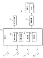
実施形態の高圧ポンプの制御装置の構成を示すブロック図である。
実施形態の高圧ポンプの制御弁が作動した場合におけるカムプロフィール、駆動信号、コイル駆動電流、第1弁体及び第2弁体の変位、高圧ポンプの振動、並びに高圧ポンプの行程の推移を示すタイムチャートである。
実施形態の高圧ポンプの制御弁が未作動の場合におけるカムプロフィール、駆動信号、コイル駆動電流、第1弁体及び第2弁体の変位、高圧ポンプの振動、並びに高圧ポンプの行程の推移を示すタイムチャートである。
実施形態の高圧ポンプの制御弁が作動した場合における駆動信号、コイル駆動電流、及びコイル駆動電流の変化速度の推移を示すタイムチャートである。
実施形態の高圧ポンプの制御弁が未作動の場合における駆動信号、コイル駆動電流、及びコイル駆動電流の変化速度の推移を示すタイムチャートである。
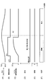
実施形態の高圧ポンプのカムプロフィール、駆動信号、コイル駆動電流、振動、音低減制御の実施の有無、ポンプ作動判定、及び通電制御量の推移を示すタイムチャートである。
実施形態の高圧ポンプのECUにより実行される処理の手順を示すフローチャートである。
以下、高圧ポンプの制御装置の一実施形態について説明する。図1に示されるように、本実施形態の高圧ポンプ20は、燃料供給システム1の一要素である。燃料供給システム1は、内燃機関である筒内噴射式の車載ガソリンエンジンに燃料を供給するシステムである。具体的には、燃料供給システム1には、燃料タンク11が設けられている。燃料タンク11内に貯留された燃料は、電磁駆動式の低圧ポンプであるフィードポンプ12により汲み上げられ、低圧配管13を介して高圧ポンプ20に導入される。高圧ポンプ20に導入された燃料は、高圧ポンプ20で高圧化された後、蓄圧室14に圧送される。圧送された高圧燃料は、蓄圧室14内に高圧状態で蓄えられた後、エンジンの各気筒に設けられたインジェクタ15からエンジンの気筒内に直接噴射される。
次に、高圧ポンプ20の構造について詳しく説明する。高圧ポンプ20は、プランジャの移動に伴い燃料の吸引及び吐出を行う、いわゆるプランジャポンプである。
図1に示されるように、高圧ポンプ20は、プランジャ21と、カム22と、制御弁30とを備えている。
プランジャ21は、軸方向に往復移動可能にシリンダ23内に挿入されている。プランジャ21の軸方向の一端部21aは、図示しないスプリングの付勢力によりカム22に当接している。カム22は、複数のカム山を有している。カム22は、エンジンの出力軸であるクランク軸16の回転に伴い回転するカム軸24に固定されている。これにより、エンジン運転時にクランク軸16が回転すると、カム22の回転に伴いプランジャ21がシリンダ23内を軸方向に移動する。
高圧ポンプ20は、加圧室25、燃料吸入通路26、及び燃料排出通路27を備えている。加圧室25は、プランジャ21の他方の端部21bに配置されている。加圧室25は、燃料吸入通路26及び燃料排出通路27に連通されている。これらの通路26,27を介して加圧室25への燃料の導入及び排出が行われる。具体的には、プランジャ21が加圧室25の容量を大きくする側に移動すると、すなわち加圧室25からカム22に向かう方向に移動すると、低圧配管13内の低圧の燃料が燃料吸入通路26を介して加圧室25に導入される。また、プランジャ21が加圧室25の容積を小さくする側に移動すると、すなわちカム22から加圧室25に向かう方向に移動すると、加圧室25内の燃料が燃料排出通路27へ排出される。
制御弁30は、加圧室25の上流側に、換言すれば高圧ポンプ20の燃料入口部分に配置されている。制御弁30は、高圧ポンプ20の燃料吐出量を調整する。制御弁30は、電磁部としてのコイル31と、第1弁体32と、第2弁体33とを備えている。制御弁30は、コイル31の通電制御により第1弁体32を軸方向に変位させることで、加圧室25への燃料の供給及び遮断を行う開閉弁として構成されている。制御弁30の内部には、燃料吸入通路26が形成されている。燃料吸入通路26には、燃料の流れ方向に沿って第1弁室34及び第2弁室35が順に形成されている。
第1弁室34には、第1弁体32が収容されている。第1弁体32は、コイル31の通電/非通電により変位する。第1弁体32は、コイル31の非通電時には、付勢手段としてのスプリング36の付勢力により開弁位置に保持されている。第1弁体32は、コイル31の通電時には、スプリング36の付勢力に抗して、ストッパ37に当接する位置である閉弁位置に変位する。このように、ストッパ37は、第1弁体32の移動を規制する移動規制部材としての機能を有している。コイル31の入力端子側には電源53が接続されている。この電源53からコイル31への電力供給が行われている。
第2弁室35には、第2弁体33が収容されている。第2弁体33は、第1弁体32と同軸上に配置されている。第2弁体33は、第1弁体32の移動に伴い変位する。具体的には、第2弁体33は、第1弁体32が開弁位置にあるときには、第1弁体32によって軸方向に押圧されている。これにより、第2弁体33は、スプリング38の付勢力に抗してストッパ39に当接する位置である開弁位置で保持される。この状態では、第2弁体33が弁座40から離座しているため、低圧配管13と加圧室25とが連通し、加圧室25への低圧燃料の導入が許容される。一方、コイル31の通電に伴い第1弁体32が閉弁位置にあるときには、第2弁体33は、第1弁体32による押圧から開放されることにより、スプリング38の付勢力によって弁座40に着座する位置である閉弁位置に保持される。この状態では、低圧配管13と加圧室25との連通が遮断されるため、加圧室25への低圧燃料の導入が遮断される。
加圧室25は、燃料排出通路27を介して蓄圧室14に接続されている。燃料排出通路27の途中には逆止弁41が設けられている。逆止弁41は、弁体42と、スプリング43とを備えている。弁体42は、加圧室25内の燃料圧力が所定圧以上になった場合に軸方向に変位する。具体的には、加圧室25内の燃料圧力が所定圧未満の場合には、スプリング43の付勢力によって弁体42が閉弁位置で保持された状態となり、加圧室25から燃料排出通路27への燃料の排出が遮断される。加圧室25内の燃料圧力が所定圧以上になると、スプリング43の付勢力に抗して弁体42が変位して開弁し、加圧室25から燃料排出通路27への燃料の排出が許容される。
燃料供給システム1は、クランク角センサ51、燃圧センサ52、及び電流センサ54等の各種センサを備えている。クランク角センサ51は、エンジンの所定クランク角毎に矩形状のクランク角信号を出力する。燃圧センサ52は、蓄圧室14内の燃料圧力Pfを検出する。電流センサ54は、コイル31の駆動電流Icを検出する。以下、コイル31の駆動電流Icを「コイル駆動電流Ic」と称する。
燃料供給システム1は、ECU(Electronic Control Unit)60を備えている。本実施形態では、ECU60が制御部に相当する。ECU60は、CPUや記憶装置等よりなるマイクロコンピュータを主体として構成される。具体的には、ECU60は、前述した各種センサ等から各々検出信号を取得し、それらの検出信号に基づいて、エンジンの運転に関する各種パラメータの制御量を演算する。ECU60は、その制御量の演算値に基づいてインジェクタ15や制御弁30の駆動を制御する。
また、ECU60は、燃圧センサ52により検出される実燃圧を目標燃圧に追従させるべく、高圧ポンプ20の吐出量制御として、実燃圧と目標燃圧との偏差に基づくフィードバック制御を実行する。これにより、蓄圧室14内の燃料圧力が、エンジンの運転状態に応じた目標燃圧となるように制御される。
具体的には、ECU60は、制御弁30の開弁タイミングを制御することにより高圧ポンプ20の燃料吐出量を調整している。より詳しくは、ECU60は、駆動回路70を介して制御弁30のコイル31に接続されている。ECU60は、コイル31の通電制御量に応じた駆動信号を生成し、この駆動信号を駆動回路70に出力することにより制御弁30の開弁及び閉弁を制御する。通電制御量は、コイル31に供給される電流の大きさを示す制御指令値である。
ところで、高圧ポンプ20から燃料を吐出させるべく制御弁30の開弁/閉弁を切り替える場合、第1弁体32がストッパ37に衝突することにより騒音が発生し、車両の搭乗者に違和感を与えることがある。このような騒音は、コイル31に与えられる電気エネルギが大きいほど大きくなる。すなわち、コイル31に与えられる電気エネルギが大きくなるほど、第1弁体32の移動速度が上昇するため、第1弁体32がストッパ37に衝突するに発生する衝突エネルギが大きくなり、作動音が大きくなる。したがって、コイル31に与えられる電気エネルギを小さくして第1弁体32の移動速度を遅くすれば、第1弁体32の衝突エネルギを小さくすることができるため、作動音を小さくすることができる。そこで、本実施形態のECU60は、第1弁体32が閉弁位置に向かって移動する速度を緩慢にすることによって高圧ポンプ20の作動音を低減させる制御を行う。
一方、コイル31に与えられる電気エネルギが小さすぎると、コイル31の通電時に第1弁体32をコイル31に向かって移動させることができず、制御弁30を閉弁状態に切り替えることができなくなる。この場合、高圧ポンプ20が作動せず、高圧ポンプ20から燃料を吐出できない。
そこで、本実施形態のECU60は、高圧ポンプ20の音低減制御として、通電制御量に対して制御弁30が作動したか否かを判定し、その判定結果に基づいてコイル31の通電制御量を学習する。具体的には、ECU60は、図2に示されるように、制御量変更部610と、作動検出部611と、学習部612とを備えている。
制御量変更部610は、コイル31に対する前回の通電時に高圧ポンプ20が作動したと判定された場合に今回通電時の通電制御量を所定値だけ低減する。また、制御量変更部610は、前回の通電時に高圧ポンプ20が未作動の状態であると判定された場合に今回通電時の通電制御量を所定値だけ増加させる。
作動検出部611は、制御量変更部610により通電制御量が変更された際、電流センサ54により検出されるコイル駆動電流Icを監視し、その変化に基づいて制御弁30の作動状態を検出する。具体的には、作動検出部611は、通電制御量に対して制御弁30が作動したか否かを検出する。
学習部612は、作動検出部611による制御弁30の作動状態の検出結果に基づいて、制御量変更部610により変更された通電制御量を学習する。
次に、図3を参照して、この高圧ポンプ20の音低減制御について詳しく説明する。なお、図3(A)において、BDCはプランジャ21の下死点を示し、TDCはプランジャ21の上死点を示している。また、図3(B)の駆動信号は、制御弁30を開弁状態にする場合にオフ状態となり、制御弁30を閉弁状態にする場合にオン状態になる。
カム22の移動に伴い、図3(A)に示されるようにプランジャ21が上死点から下死点に向かって移動する期間、すなわちプランジャ21が加圧室25の容積を大きくする側に移動する期間のうち、時刻t16以降の期間では、図3(C)に示されるように、コイル31が非通電状態となっている。したがって、この期間では、図3(D)に示されるように、第1弁体32及び第2弁体33が開弁位置になっている。すなわち、第1弁体32は、スプリング36の付勢力によってストッパ37から離間した状態となっている。また、第2弁体33は、第1弁体32によってストッパ39に当接した状態になっている。これにより、加圧室25と燃料吸入通路26とが連通した状態となり、加圧室25内に燃料が導入される。よって、図3(F)に示されるように、この期間は高圧ポンプ20の吸入行程となっている。
プランジャ21が下死点から上死点に移動する期間では、加圧室25の容積が減少する。この期間では、図3(B)に示されるように、ECU60は、内燃機関の要求吐出量に応じたタイミングで駆動信号をオフ状態からオン状態に切り替える。図3(B)では、このタイミングが時刻t10となっている。すなわち、ECU60は、時刻t10でコイル31への通電を開始する。このとき、時刻t11以前では、第2弁体33が弁座40から離間した状態になっている。そのため、プランジャ21の移動に伴い、加圧室25の燃料が燃料吸入通路26側に戻される。よって、図3(F)に示されるように、この期間は高圧ポンプ20の調量行程となっている。
コイル31への通電開始により第1弁体32がコイル31に向けて吸引されると、第1弁体32がストッパ37に当接する位置まで移動する。すなわち、図3(D)に示されるように、第1弁体32が閉弁位置CL1まで移動する。このとき、第1弁体32がストッパ37に衝突することにより、図3(E)に示されるように、高圧ポンプ20に振動が生じる。また、コイル31の通電が開始された時刻t10から所定時間が経過した時刻t12になると、第2弁体33により加圧室25と燃料吸入通路26とが遮断された状態となる。この状態でプランジャ21が上死点方向に移動することにより、加圧室25内の燃料圧力が上昇するとともに、その燃料圧力の上昇に伴い高圧化された高圧燃料が燃料排出通路27側へ吐出される。したがって、時刻t12以降、高圧ポンプ20の昇圧行程及び吐出行程が行われる。
その後、図3(B)に示されるように、ECU60が時刻t13で駆動信号をオン状態からオフ状態に切り替えると、図3(C)に示されるように、コイル31が非通電状態となる。これにより、時刻t14で第1弁体32がストッパ37から離間して第2弁体33に突き当たるとともに、図3(D)に示されるように、その突き当たり状態が、時刻t14から所定時間が経過する時刻t15までの期間継続する。なお、この突き当たり状態では、第1弁体32及び第2弁体33は、第2弁体33の閉弁位置CL2で保持される。図3(E)に示されるように、このときの第1弁体32と第2弁体33との衝突により、高圧ポンプ20に振動が発生する。
その後、プランジャ21が上死点から下死点に向かって移動すると、加圧室25内の容積が増大して加圧室25内の圧力が低下する。したがって、図3(F)に示されるように、この期間は高圧ポンプ20の減圧行程となっている。これにより、第2弁室35内の燃料圧力が低下して第1弁体32及び第2弁体33の動きが許容され、時刻t15以降にそれぞれの開弁位置まで移動する。このとき、第2弁体33は、第1弁体32によって軸方向に押圧されることによりストッパ39に衝突する。これにより、図3(E)に示されるように、時刻t16で高圧ポンプ20に振動が生じる。
図3(C)に示されるように、ECU60は、コイル31の通電開始直後に、コイル駆動電流Icが第1電流値A1まで上昇するように、コイル31に印加される電圧のデューティ比を可変制御、換言すればPWM制御する。ECU60は、コイル駆動電流Icが第1電流値A1まで上昇すると、定電流制御を実行する。この定電流制御では、ECU60は、まず、コイル駆動電流Icを第1電流値A1に保持する第1定電流制御を実行する。続いて、ECU60は、第1電流値A1よりも小さい第2電流値A2で制御する第2定電流制御に移行する。
ここで、コイル31への通電に伴い、第1弁体32及び第2弁体33が移動した場合、その動きはコイル31に流れる電流の変化として表れる。具体的には、第1弁体32が移動し始めると、第1弁体32がコイル31に近づくにつれてコイル31のインダクタンスが大きくなることにより、コイル31に流れる電流が次第に小さくなる。そのため、電源53からコイル31に所定電圧を印加している場合、図3(C)に示されるように、第1弁体32が移動し始めるまでは時間とともにコイル電流が増大する。また、時刻t11で第1弁体32が開弁位置から移動し始めると、第1弁体32が閉弁位置CL1に近づくにつれてコイル駆動電流Icが徐々に減少する。また、時刻t12で第1弁体32がストッパ37に当接することにより第1弁体32の動きが止まると、インダクタンスは再び一定となり、コイル駆動電流Icが再び上昇する。すなわち、コイル31の通電に伴い第1弁体32が移動した場合、駆動信号がオン状態となっている期間では、図3(C)に示されるように、コイル駆動電流Icが増加傾向から減少傾向に一旦切り替わった後、再び増加傾向に転じる。そのため、駆動信号がオン状態となっている期間では、コイル駆動電流Icに極小値P1が表れる。
一方、閉弁に切り替える駆動信号をECU60が制御弁30に出力したにも関わらず、第1弁体32が開弁位置から変化しない場合には、駆動信号の出力後において、第1弁体32の位置が保持される。この場合、図4(A)~(F)に示されるように、駆動信号のオン/オフを切り替えたとしても、第1弁体32及び第2弁体33が正常な動きを示す場合に見られる挙動が表れない。具体的には、図4(C)に示されるように、駆動信号のオン期間におけるコイル駆動電流Icの変化が表れない。したがって、コイル駆動電流Icの変化に基づいて、制御弁30の作動の可否を判定することができる。
図5及び図6は、本実施形態のポンプ作動判定の具体的な手法を示すタイムチャートである。作動検出部611は、コイル駆動電流の変化速度(dIc/dt)、換言すればコイル駆動電流Icの微分値に基づいて、制御弁30の作動状態を検出する。
具体的には、図5(A)に示されるように、駆動信号がオフ状態からオン状態に切り替えられた際に、第1弁体32が閉弁位置まで移動した場合には、図5(B)に示されるように、駆動信号のオン期間においてコイル駆動電流Icは減少傾向を示す。そのため、図5(C)に示されるように、コイル駆動電流の変化速度(dIc/dt)は負側に変化する。これに対し、図6(A)に示されるように、駆動信号がオフ状態からオン状態に切り替えられた際に、第1弁体32が移動しなかった場合には、図6(B)に示されるように、駆動信号のオン期間においてコイル駆動電流Icは減少傾向を示さない。したがって、図6(C)に示されるように、コイル駆動電流の変化速度(dIc/dt)は、負側に変化しない。
これを利用し、作動検出部611は、図5(C)及び図6(C)に示されるように、コイル駆動電流の変化速度(dIc/dt)と判定値Thaとを比較し、コイル駆動電流の変化速度(dIc/dt)が判定値Tha以下になることに基づいて、コイル駆動電流Icの極小値P1を検出する。作動検出部611は、コイル駆動電流の変化速度(dIc/dt)が判定値Tha以下になった場合には、制御弁30が作動したと判定する。これに対し、作動検出部611は、コイル駆動電流の変化速度(dIc/dt)が判定値Thaを超えたままである場合には、制御弁30が未作動であると判定する。
次に、図7(A)~(G)を参照して、高圧ポンプ20の音低減制御の概要について説明する。
ECU60は、高圧ポンプ20の吐出量制御において通常制御が実行されている場合、すなわち図7の時刻t22以前では、コイル31に印加される電圧のデューティ比を例えば100%に設定している。この期間では、図7(B)及び(C)に示されるように、時刻t21でECU60が駆動信号をオフ状態からオン状態に切り替えると、コイル駆動電流Icが第1電流値A1まで速やかに上昇する。
ECU60は、エンジンの運転状態に応じて高圧ポンプ20の吐出量制御を通常制御から音低減制御に切り替える。図7(E)に示されるように、通常制御から音低減制御に切り替えられたタイミングは時刻t22となっている。音低減制御では、コイル31に印加される電圧のデューティ比を、通常制御時のデューティ比よりも小さくすることにより、第1弁体32の変位速度を遅くする。例えば、図7(F)及び(G)に示されるように、制御量変更部610は、時刻t24の時点において、前回の通電制御時に制御弁30の作動が時刻t23で検出されている場合には、今回の通電制御量を前回の通電制御量よりも所定値Δα1だけ減少させる電力低減制御を実行する。
また、制御量変更部610は、時刻t26の時点において、前回の通電制御時に制御弁30の未作動が時刻t25で検出されている場合には、今回の通電制御量を前回の通電制御量よりも所定値β1だけ増加させる電力増加制御を実行する。
学習部612は、これらの電力低減制御と電力増加制御とを交互に繰り返すことにより、第1弁体32を閉弁位置まで移動可能な最小の通電制御量を学習する。これにより、制御弁30の閉弁動作を確保可能な範囲で第1弁体32を可能な限り低速で移動させることができるため、第1弁体32のストッパ37への衝突時の振動を小さくすることができるとともに、その衝突時の作動音を小さくすることができる。
なお、本実施形態では、電力低減制御による通電制御量の変更量Δα1と、電力増加制御による通電制御量の変更量Δβ1とが同一の値に設定されている。そのため、前回の通電時に制御弁30の作動が検出されて通電制御量をΔα1だけ低減させた際に制御弁30が未作動であった場合、通電制御量がΔβ1だけ増加することにより、基本的には、制御弁30が再び作動する。
ところで、このような燃料供給システム1では、例えばアイドル運転時や燃料カット制御時に、インジェクタ15から噴射される燃料量が通常時と比較して減少する。インジェクタ15の燃料噴射量が減少すると、高圧ポンプ20の作動時間、より詳しくは制御弁30の作動時間が短くなる。この場合、駆動信号のオン時間が短くなるため、駆動信号に基づくコイル駆動電流Icの変化も小さくなる。すなわち、コイル駆動電流の変化速度(dIc/dt)の変化も小さくなる。そのため、図5及び図6に示されるように、コイル駆動電流の変化速度(dIc/dt)の変化に基づいて制御弁30の作動状態を検出する場合、駆動信号が短くなった際にコイル駆動電流の変化速度(dIc/dt)の変化を作動検出部611が検出できないおそれがある。このような場合、実際には制御弁30が極僅かに作動しているにも関わらず、その作動状態を作動検出部611が検出できないため、作動検出部611が、制御弁30が未作動であると誤検出するおそれがある。このような状況では、その作動検出部611の検出結果に基づいて学習部612が通電制御量を学習すると、適切な通電制御量を学習することができないため、結果的に高圧ポンプ20の作動音を低減できないおそれがある。
そこで、本実施形態のECU60は、通電制御量に対する制御弁30の作動時間が、制御弁30の作動状態を検出可能な時間よりも短くなる状況であるか否かを判定する。具体的には、図2に示されるように、ECU60は、この判定を行う判定部613を備えている。そして、通電制御量に対する制御弁30の作動時間が、制御弁30の作動状態を検出可能な時間よりも短くなる状況であると判定部613により判定される場合、学習部612が通電制御量の学習を禁止する。
次に、図8を参照して、この学習処理の手順について詳しく説明する。なお、ECU60は、図8に示される処理を所定の演算周期で繰り返し実行する。
図8に示されるように、判定部613は、ステップS1の処理として、制御弁30の作動時間が、制御弁30の作動状態を検出可能な時間よりも短くなる状況であるか否かを判定する。判定部613は、例えば以下の(a1)~(a5)に示される条件が満たされることをもって、制御弁30の作動時間が、制御弁30の作動状態を検出可能な時間よりも短くなる状況であるか否かを判定する。なお、判定部613は、(a1)~(a5)に示される条件のうちの1つ乃至複数の条件を用いることができる。また、判定部613は、複数の条件を用いる場合には、それらのOR条件及びAND条件のいずれの条件を用いてもよい。
(a1)高圧ポンプ20の燃料吐出量の要求値が所定値以下であること。この条件は、例えばアイドル運転時に満たされる条件である。(a2)インジェクタ15の燃料噴射量を制限する燃料カット制御の実行中であること。(a3)車両が減速中であること。(a4)内燃機関の負荷状態が低負荷状態であること。(a5)クランク軸16の回転速度が所定の回転速度以下であること。
判定部613がステップS1の処理で行程判断した場合、ECU60はステップS2の処理に移行しない。これにより、学習部612による通電制御量の学習が禁止される。判定部613が否定判断した場合、作動検出部611が、ステップS2の処理として、制御弁30の作動状態を検出する。具体的には、作動検出部611は、制御弁30の作動状態と相関関係のあるコイル駆動電流の変化速度(dIc/dt)を検出する。
作動検出部611は、ステップS2に続くステップS3の処理として、制御弁30が作動したか否かを判断する。具体的には、作動検出部611は、図5及び図6に示されるように、コイル駆動電流の変化速度(dIc/dt)と判定値Thaとの比較に基づいて制御弁30が作動したか否かを判断する。
作動検出部611がステップS3の処理で肯定判断した場合、制御量変更部610は、ステップS4の処理として、通電制御量を所定値Δα1だけ減少させる。
作動検出部611がステップS3の処理で否定判断した場合、制御量変更部610は、ステップS5の処理として、通電制御量を所定値Δβ1だけ増加させる。次に、学習部612は、ステップS6の処理として、所定値β1だけ増加させた通電制御量を通電制御量の最適値としてECU60の記憶装置に記憶させる。
以上説明した本実施形態の高圧ポンプ20のECU60によれば、以下の(1)~(3)に示される作用及び効果を得ることができる。
(1)ECU60は、制御量変更部610と、作動検出部611と、学習部612と、判定部613とを備えている。制御量変更部610は、制御弁30の通電制御量を変更する。作動検出部611は、通電制御量を変更した際の制御弁30の作動状態を検出する。学習部612は、高圧ポンプ20の作動音を低減させるべく、制御弁30の作動状態に基づいて通電制御量を学習する。判定部613は、通電制御量に対する制御弁30の作動時間が、制御弁30の作動状態を検出可能な時間よりも短くなる状況であるか否かを判断する。学習部612は、通電制御量に対する制御弁30の作動時間が、制御弁30の作動状態を検出可能な時間よりも短くなる状況であると判定される場合には、学習を禁止する。これにより、制御弁30の作動状態の誤検出を回避することができるため、通電制御量の学習精度を向上させることができる。結果的に、高圧ポンプ20の作動音を低減させることができる。
(2)判定部613は、上記の(a1)~(a5)に示される条件が満たされることをもって、制御弁30の作動時間が、制御弁30の作動状態を検出可能な時間よりも短くなる状況であるか否かを判定する。これにより、この判定を容易に行うことができる。
(3)作動検出部611は、制御弁30のコイル駆動電流Icを監視し、コイル駆動電流Icの変化に基づいて制御弁30が作動したか否かを検出する。具体的には、作動検出部611は、コイル駆動電流Icの極小値P1の検出に基づいて制御弁30の作動を検出する。これにより、制御弁30の作動状態を容易に検出することができる。
なお、上記実施形態は、以下の形態にて実施することもできる。上記実施形態では、作動検出部611がコイル駆動電流の変化速度(dIc/dt)に基づいてコイル駆動電流Icの変化を検出したが、コイル駆動電流Icの変化の検出方法は適宜変更可能である。例えば、駆動信号のオン期間において、コイル駆動電流Icの最大値をホールドするとともに、そのホールド値に対する今回の計測値の変化量を算出する。そして、この算出した変化量に基づいてコイル駆動電流Icの変化を検出してもよい。
作動検出部611は、コイル駆動電流Icが減少傾向から増加傾向に転じることをもって、制御弁30の作動を検出してもよい。
作動検出部611は、例えば図2に示される電圧センサ55により制御弁30の駆動電圧を監視し、この駆動電圧の変化に基づいて制御弁30が作動したか否かを検出してもよい。
電力低減制御における通電制御量の変更量Δα1、及び電力増加制御における通電制御量の変更量Δβ1は、変更可能な値であってもよい。また、変更量Δα1及び変更量Δβ1は互いに異なる値であってもよい。
作動検出部611は、コイル駆動電流の変化速度(dIc/dt)が判定値Tha以下である状態が所定時間継続することをもって、制御弁30が作動したと判定してもよい。
制御弁30の駆動を制御する方法は、コイル31に印加される電圧のデューティ比を可変制御するという方法に限らず、適宜の制御手法を用いることができる。
高圧ポンプ20は、2つの弁体を有するものに限らず、1つの弁体のみを有するものであってもよい。
上記実施形態のECU60の構成は、ガソリンエンジンの燃料供給システム1に限らず、例えばディーゼルエンジンの燃料供給システムに適用することもできる。
ECU60が提供する手段及び/又は機能は、実体的な記憶装置に記憶されたソフトウェア及びそれを実行するコンピュータ、ソフトウェアのみ、ハードウェアのみ、あるいはそれらの組み合わせにより提供することができる。例えばECU60がハードウェアである電子回路により提供される場合、それは多数の論理回路を含むデジタル回路、またはアナログ回路により提供することができる。
本開示は上記の具体例に限定されるものではない。すなわち、上記の具体例に、当業者が適宜設計変更を加えたものも、本開示の特徴を備えている限り、本開示の範囲に包含される。例えば、前述した各具体例が備える各要素及びその配置や条件等は、例示したものに限定されるわけではなく適宜変更することができる。また、前述した実施形態が備える各要素は、技術的に可能な限りにおいて組み合わせることができ、これらを組み合わせたものも本開示の特徴を含む限り本開示の範囲に包含される。
本開示は、実施例に準拠して記述されたが、本開示は当該実施例や構造に限定されるものではないと理解される。本開示は、様々な変形例や均等範囲内の変形をも包含する。加えて、様々な組み合わせや形態、さらには、それらに一要素のみ、それ以上、あるいはそれ以下、を含む他の組み合わせや形態をも、本開示の範疇や思想範囲に入るものである。
Claims (8)
- 通電制御により制御弁(30)を開弁及び閉弁させることにより高圧ポンプ(20)の燃料吐出量を調整する高圧ポンプ(20)の制御装置(60)であって、
前記制御弁(30)の通電制御量を変更する制御量変更部(610)と、
前記通電制御量を変更した際の前記制御弁(30)の作動状態を検出する作動検出部(611)と、
前記高圧ポンプ(20)の作動音を低減させるべく、前記制御弁(30)の作動状態に基づいて前記通電制御量を学習する学習部(612)と、
前記通電制御量に対する前記制御弁(30)の作動時間が、前記制御弁(30)の作動状態を検出可能な時間よりも短くなる状況であるか否かを判定する判定部(613)と、を備え、
前記学習部(612)は、
前記通電制御量に対する前記制御弁(30)の作動時間が、前記制御弁(30)の作動状態を検出可能な時間よりも短くなる状況であると判定される場合には、前記学習を禁止する
高圧ポンプ(20)の制御装置。 - 前記判定部(613)は、
前記燃料吐出量の要求値が所定値以下であることをもって、前記通電制御量に対する前記制御弁(30)の作動時間が、前記制御弁(30)の作動状態を検出可能な時間よりも短くなる状況であると判定する
請求項1に記載の高圧ポンプ(20)の制御装置。 - 前記高圧ポンプ(20)は、
車両の内燃機関のインジェクタ(15)に供給される燃料が蓄えられる蓄圧室(14)に燃料を圧送するものであり、
前記判定部(613)は、
前記インジェクタ(15)の燃料噴射量を制限する燃料カット制御の実行中であることをもって、前記通電制御量に対する前記制御弁(30)の作動時間が、前記制御弁(30)の作動状態を検出可能な時間よりも短くなる状況であると判定する
請求項1に記載の高圧ポンプ(20)の制御装置。 - 前記高圧ポンプ(20)は、
車両の内燃機関のインジェクタ(15)に供給される燃料が蓄えられる蓄圧室(14)に燃料を圧送するものであり、
前記判定部(613)は、
前記車両が減速中であることをもって、前記通電制御量に対する前記制御弁(30)の作動時間が、前記制御弁(30)の作動状態を検出可能な時間よりも短くなる状況であると判定する
請求項1に記載の高圧ポンプ(20)の制御装置。 - 前記高圧ポンプ(20)は、
車両の内燃機関のインジェクタ(15)に供給される燃料が蓄えられる蓄圧室(14)に燃料を圧送するものであり、
前記判定部(613)は、
前記内燃機関の負荷状態が低負荷状態であることをもって、前記通電制御量に対する前記制御弁(30)の作動時間が、前記制御弁(30)の作動状態を検出可能な時間よりも短くなる状況であると判定する
請求項1に記載の高圧ポンプ(20)の制御装置。 - 前記作動検出部(611)は、
前記制御弁(30)の駆動電流を監視し、前記駆動電流の変化に基づいて前記制御弁(30)の作動状態を検出する
請求項1~5のいずれか一項に記載の高圧ポンプ(20)の制御装置。 - 前記作動検出部(611)は、
前記駆動電流の極小値の検出に基づいて前記制御弁(30)が作動したと判定する
請求項6に記載の高圧ポンプ(20)の制御装置。 - 前記作動検出部(611)は、
前記制御弁(30)の駆動電圧を監視し、前記駆動電圧の変化に基づいて前記制御弁(30)の作動状態を検出する
請求項1~5のいずれか一項に記載の高圧ポンプ(20)の制御装置。
Priority Applications (2)
| Application Number | Priority Date | Filing Date | Title |
|---|---|---|---|
| US15/766,949 US10473077B2 (en) | 2015-10-22 | 2016-10-14 | Control device for high-pressure pump |
| DE112016004817.3T DE112016004817T5 (de) | 2015-10-22 | 2016-10-14 | Steuervorrichtung für eine Hochdruckpumpe |
Applications Claiming Priority (2)
| Application Number | Priority Date | Filing Date | Title |
|---|---|---|---|
| JP2015208341A JP6341176B2 (ja) | 2015-10-22 | 2015-10-22 | 高圧ポンプの制御装置 |
| JP2015-208341 | 2015-10-22 |
Publications (1)
| Publication Number | Publication Date |
|---|---|
| WO2017069052A1 true WO2017069052A1 (ja) | 2017-04-27 |
Family
ID=58557448
Family Applications (1)
| Application Number | Title | Priority Date | Filing Date |
|---|---|---|---|
| PCT/JP2016/080506 Ceased WO2017069052A1 (ja) | 2015-10-22 | 2016-10-14 | 高圧ポンプの制御装置 |
Country Status (4)
| Country | Link |
|---|---|
| US (1) | US10473077B2 (ja) |
| JP (1) | JP6341176B2 (ja) |
| DE (1) | DE112016004817T5 (ja) |
| WO (1) | WO2017069052A1 (ja) |
Citations (4)
| Publication number | Priority date | Publication date | Assignee | Title |
|---|---|---|---|---|
| JP2010014109A (ja) * | 2008-06-04 | 2010-01-21 | Denso Corp | 燃料供給装置 |
| JP2010196472A (ja) * | 2009-02-23 | 2010-09-09 | Denso Corp | 内燃機関の燃料供給制御装置 |
| JP2010533820A (ja) * | 2007-07-27 | 2010-10-28 | ロベルト・ボッシュ・ゲゼルシャフト・ミト・ベシュレンクテル・ハフツング | 内燃機関の燃料噴射装置の制御方法 |
| JP2015045322A (ja) * | 2013-08-02 | 2015-03-12 | 株式会社デンソー | 高圧ポンプの制御装置 |
Family Cites Families (18)
| Publication number | Priority date | Publication date | Assignee | Title |
|---|---|---|---|---|
| JP4042057B2 (ja) * | 2003-11-04 | 2008-02-06 | 株式会社デンソー | バルブ開度調整装置およびコモンレール式燃料噴射装置 |
| JP4052261B2 (ja) * | 2004-03-02 | 2008-02-27 | トヨタ自動車株式会社 | 内燃機関の燃料供給装置 |
| JP4333619B2 (ja) * | 2005-04-08 | 2009-09-16 | 株式会社デンソー | 筒内噴射式の内燃機関の始動制御装置 |
| JP4333635B2 (ja) * | 2005-05-24 | 2009-09-16 | 株式会社デンソー | 筒内噴射式の内燃機関の制御装置 |
| US7765991B2 (en) * | 2006-08-09 | 2010-08-03 | Ford Global Technologies, Llc | Fuel delivery control for internal combustion engine |
| JP4349451B2 (ja) * | 2007-08-23 | 2009-10-21 | 株式会社デンソー | 燃料噴射制御装置およびそれを用いた燃料噴射システム |
| US7918208B2 (en) * | 2008-06-04 | 2011-04-05 | Denso Corporation | Fuel supply apparatus |
| US9341181B2 (en) | 2012-03-16 | 2016-05-17 | Denso Corporation | Control device of high pressure pump |
| JP2015002142A (ja) | 2013-06-18 | 2015-01-05 | 株式会社東芝 | ガス遮断器 |
| JP2015014221A (ja) | 2013-07-04 | 2015-01-22 | 株式会社デンソー | 高圧ポンプの制御装置 |
| JP2015017553A (ja) | 2013-07-11 | 2015-01-29 | 株式会社デンソー | 高圧ポンプの制御方法 |
| US9353699B2 (en) * | 2014-03-31 | 2016-05-31 | Ford Global Technologies, Llc | Rapid zero flow lubrication methods for a high pressure pump |
| JP6149790B2 (ja) | 2014-04-23 | 2017-06-21 | サミー株式会社 | 遊技機 |
| JP6308012B2 (ja) * | 2014-05-16 | 2018-04-11 | 株式会社デンソー | 高圧ポンプの制御装置 |
| JP6350226B2 (ja) * | 2014-11-05 | 2018-07-04 | 株式会社デンソー | 内燃機関の燃料噴射制御装置 |
| US9611801B2 (en) * | 2014-12-15 | 2017-04-04 | Ford Global Technologies, Llc | Methods and systems for fixed and variable pressure fuel injection |
| US9657680B2 (en) * | 2014-12-30 | 2017-05-23 | Ford Global Technologies, Llc | Zero flow lubrication for a high pressure fuel pump |
| KR101744807B1 (ko) * | 2015-06-15 | 2017-06-08 | 현대자동차 주식회사 | 엔진 제어 장치 및 방법 |
-
2015
- 2015-10-22 JP JP2015208341A patent/JP6341176B2/ja active Active
-
2016
- 2016-10-14 DE DE112016004817.3T patent/DE112016004817T5/de active Pending
- 2016-10-14 US US15/766,949 patent/US10473077B2/en active Active
- 2016-10-14 WO PCT/JP2016/080506 patent/WO2017069052A1/ja not_active Ceased
Patent Citations (4)
| Publication number | Priority date | Publication date | Assignee | Title |
|---|---|---|---|---|
| JP2010533820A (ja) * | 2007-07-27 | 2010-10-28 | ロベルト・ボッシュ・ゲゼルシャフト・ミト・ベシュレンクテル・ハフツング | 内燃機関の燃料噴射装置の制御方法 |
| JP2010014109A (ja) * | 2008-06-04 | 2010-01-21 | Denso Corp | 燃料供給装置 |
| JP2010196472A (ja) * | 2009-02-23 | 2010-09-09 | Denso Corp | 内燃機関の燃料供給制御装置 |
| JP2015045322A (ja) * | 2013-08-02 | 2015-03-12 | 株式会社デンソー | 高圧ポンプの制御装置 |
Also Published As
| Publication number | Publication date |
|---|---|
| DE112016004817T5 (de) | 2018-07-05 |
| JP6341176B2 (ja) | 2018-06-13 |
| JP2017082597A (ja) | 2017-05-18 |
| US10473077B2 (en) | 2019-11-12 |
| US20180291852A1 (en) | 2018-10-11 |
Similar Documents
| Publication | Publication Date | Title |
|---|---|---|
| JP6221828B2 (ja) | 高圧ポンプの制御装置 | |
| US10890176B2 (en) | Control device for high pressure pump | |
| CN105673239B (zh) | 直接喷射泵控制 | |
| US9341181B2 (en) | Control device of high pressure pump | |
| US10655613B2 (en) | High-pressure pump control unit | |
| US10330064B2 (en) | Control device for high-pressure pump | |
| US10655614B2 (en) | Device for controlling high-pressure pump | |
| US7918208B2 (en) | Fuel supply apparatus | |
| JP2016205368A (ja) | 高圧ポンプの制御装置 | |
| JP2015021428A (ja) | 高圧ポンプの制御装置 | |
| JP5692131B2 (ja) | 高圧ポンプの制御装置 | |
| WO2014119289A1 (ja) | 高圧ポンプの制御装置 | |
| JP6222338B2 (ja) | 高圧ポンプの制御装置 | |
| JP6341176B2 (ja) | 高圧ポンプの制御装置 | |
| JP6323168B2 (ja) | 高圧ポンプの制御装置 | |
| JP7172756B2 (ja) | 高圧ポンプの制御装置 | |
| JP5812517B2 (ja) | 高圧ポンプの制御装置 | |
| JP6519669B2 (ja) | 高圧ポンプの制御装置 | |
| WO2016170744A1 (ja) | 高圧ポンプの制御装置 |
Legal Events
| Date | Code | Title | Description |
|---|---|---|---|
| 121 | Ep: the epo has been informed by wipo that ep was designated in this application |
Ref document number: 16857367 Country of ref document: EP Kind code of ref document: A1 |
|
| WWE | Wipo information: entry into national phase |
Ref document number: 15766949 Country of ref document: US |
|
| WWE | Wipo information: entry into national phase |
Ref document number: 112016004817 Country of ref document: DE |
|
| 122 | Ep: pct application non-entry in european phase |
Ref document number: 16857367 Country of ref document: EP Kind code of ref document: A1 |