WO2017069042A1 - ハイブリッド駆動装置 - Google Patents
ハイブリッド駆動装置 Download PDFInfo
- Publication number
- WO2017069042A1 WO2017069042A1 PCT/JP2016/080396 JP2016080396W WO2017069042A1 WO 2017069042 A1 WO2017069042 A1 WO 2017069042A1 JP 2016080396 W JP2016080396 W JP 2016080396W WO 2017069042 A1 WO2017069042 A1 WO 2017069042A1
- Authority
- WO
- WIPO (PCT)
- Prior art keywords
- gear
- input
- drive device
- motor
- hybrid drive
- Prior art date
- Legal status (The legal status is an assumption and is not a legal conclusion. Google has not performed a legal analysis and makes no representation as to the accuracy of the status listed.)
- Ceased
Links
Images




Classifications
-
- B—PERFORMING OPERATIONS; TRANSPORTING
- B60—VEHICLES IN GENERAL
- B60K—ARRANGEMENT OR MOUNTING OF PROPULSION UNITS OR OF TRANSMISSIONS IN VEHICLES; ARRANGEMENT OR MOUNTING OF PLURAL DIVERSE PRIME-MOVERS IN VEHICLES; AUXILIARY DRIVES FOR VEHICLES; INSTRUMENTATION OR DASHBOARDS FOR VEHICLES; ARRANGEMENTS IN CONNECTION WITH COOLING, AIR INTAKE, GAS EXHAUST OR FUEL SUPPLY OF PROPULSION UNITS IN VEHICLES
- B60K1/00—Arrangement or mounting of electrical propulsion units
-
- B—PERFORMING OPERATIONS; TRANSPORTING
- B60—VEHICLES IN GENERAL
- B60K—ARRANGEMENT OR MOUNTING OF PROPULSION UNITS OR OF TRANSMISSIONS IN VEHICLES; ARRANGEMENT OR MOUNTING OF PLURAL DIVERSE PRIME-MOVERS IN VEHICLES; AUXILIARY DRIVES FOR VEHICLES; INSTRUMENTATION OR DASHBOARDS FOR VEHICLES; ARRANGEMENTS IN CONNECTION WITH COOLING, AIR INTAKE, GAS EXHAUST OR FUEL SUPPLY OF PROPULSION UNITS IN VEHICLES
- B60K17/00—Arrangement or mounting of transmissions in vehicles
- B60K17/04—Arrangement or mounting of transmissions in vehicles characterised by arrangement, location or kind of gearing
-
- B—PERFORMING OPERATIONS; TRANSPORTING
- B60—VEHICLES IN GENERAL
- B60K—ARRANGEMENT OR MOUNTING OF PROPULSION UNITS OR OF TRANSMISSIONS IN VEHICLES; ARRANGEMENT OR MOUNTING OF PLURAL DIVERSE PRIME-MOVERS IN VEHICLES; AUXILIARY DRIVES FOR VEHICLES; INSTRUMENTATION OR DASHBOARDS FOR VEHICLES; ARRANGEMENTS IN CONNECTION WITH COOLING, AIR INTAKE, GAS EXHAUST OR FUEL SUPPLY OF PROPULSION UNITS IN VEHICLES
- B60K6/00—Arrangement or mounting of plural diverse prime-movers for mutual or common propulsion, e.g. hybrid propulsion systems comprising electric motors and internal combustion engines
- B60K6/20—Arrangement or mounting of plural diverse prime-movers for mutual or common propulsion, e.g. hybrid propulsion systems comprising electric motors and internal combustion engines the prime-movers consisting of electric motors and internal combustion engines, e.g. HEVs
- B60K6/22—Arrangement or mounting of plural diverse prime-movers for mutual or common propulsion, e.g. hybrid propulsion systems comprising electric motors and internal combustion engines the prime-movers consisting of electric motors and internal combustion engines, e.g. HEVs characterised by apparatus, components or means specially adapted for HEVs
- B60K6/40—Arrangement or mounting of plural diverse prime-movers for mutual or common propulsion, e.g. hybrid propulsion systems comprising electric motors and internal combustion engines the prime-movers consisting of electric motors and internal combustion engines, e.g. HEVs characterised by apparatus, components or means specially adapted for HEVs characterised by the assembly or relative disposition of components
-
- B—PERFORMING OPERATIONS; TRANSPORTING
- B60—VEHICLES IN GENERAL
- B60K—ARRANGEMENT OR MOUNTING OF PROPULSION UNITS OR OF TRANSMISSIONS IN VEHICLES; ARRANGEMENT OR MOUNTING OF PLURAL DIVERSE PRIME-MOVERS IN VEHICLES; AUXILIARY DRIVES FOR VEHICLES; INSTRUMENTATION OR DASHBOARDS FOR VEHICLES; ARRANGEMENTS IN CONNECTION WITH COOLING, AIR INTAKE, GAS EXHAUST OR FUEL SUPPLY OF PROPULSION UNITS IN VEHICLES
- B60K6/00—Arrangement or mounting of plural diverse prime-movers for mutual or common propulsion, e.g. hybrid propulsion systems comprising electric motors and internal combustion engines
- B60K6/20—Arrangement or mounting of plural diverse prime-movers for mutual or common propulsion, e.g. hybrid propulsion systems comprising electric motors and internal combustion engines the prime-movers consisting of electric motors and internal combustion engines, e.g. HEVs
- B60K6/42—Arrangement or mounting of plural diverse prime-movers for mutual or common propulsion, e.g. hybrid propulsion systems comprising electric motors and internal combustion engines the prime-movers consisting of electric motors and internal combustion engines, e.g. HEVs characterised by the architecture of the hybrid electric vehicle
- B60K6/48—Parallel type
-
- B—PERFORMING OPERATIONS; TRANSPORTING
- B60—VEHICLES IN GENERAL
- B60K—ARRANGEMENT OR MOUNTING OF PROPULSION UNITS OR OF TRANSMISSIONS IN VEHICLES; ARRANGEMENT OR MOUNTING OF PLURAL DIVERSE PRIME-MOVERS IN VEHICLES; AUXILIARY DRIVES FOR VEHICLES; INSTRUMENTATION OR DASHBOARDS FOR VEHICLES; ARRANGEMENTS IN CONNECTION WITH COOLING, AIR INTAKE, GAS EXHAUST OR FUEL SUPPLY OF PROPULSION UNITS IN VEHICLES
- B60K6/00—Arrangement or mounting of plural diverse prime-movers for mutual or common propulsion, e.g. hybrid propulsion systems comprising electric motors and internal combustion engines
- B60K6/20—Arrangement or mounting of plural diverse prime-movers for mutual or common propulsion, e.g. hybrid propulsion systems comprising electric motors and internal combustion engines the prime-movers consisting of electric motors and internal combustion engines, e.g. HEVs
- B60K6/50—Architecture of the driveline characterised by arrangement or kind of transmission units
- B60K6/54—Transmission for changing ratio
- B60K6/543—Transmission for changing ratio the transmission being a continuously variable transmission
-
- B—PERFORMING OPERATIONS; TRANSPORTING
- B60—VEHICLES IN GENERAL
- B60L—PROPULSION OF ELECTRICALLY-PROPELLED VEHICLES; SUPPLYING ELECTRIC POWER FOR AUXILIARY EQUIPMENT OF ELECTRICALLY-PROPELLED VEHICLES; ELECTRODYNAMIC BRAKE SYSTEMS FOR VEHICLES IN GENERAL; MAGNETIC SUSPENSION OR LEVITATION FOR VEHICLES; MONITORING OPERATING VARIABLES OF ELECTRICALLY-PROPELLED VEHICLES; ELECTRIC SAFETY DEVICES FOR ELECTRICALLY-PROPELLED VEHICLES
- B60L50/00—Electric propulsion with power supplied within the vehicle
- B60L50/10—Electric propulsion with power supplied within the vehicle using propulsion power supplied by engine-driven generators, e.g. generators driven by combustion engines
- B60L50/16—Electric propulsion with power supplied within the vehicle using propulsion power supplied by engine-driven generators, e.g. generators driven by combustion engines with provision for separate direct mechanical propulsion
-
- F—MECHANICAL ENGINEERING; LIGHTING; HEATING; WEAPONS; BLASTING
- F16—ENGINEERING ELEMENTS AND UNITS; GENERAL MEASURES FOR PRODUCING AND MAINTAINING EFFECTIVE FUNCTIONING OF MACHINES OR INSTALLATIONS; THERMAL INSULATION IN GENERAL
- F16H—GEARING
- F16H3/00—Toothed gearings for conveying rotary motion with variable gear ratio or for reversing rotary motion
- F16H3/44—Toothed gearings for conveying rotary motion with variable gear ratio or for reversing rotary motion using gears having orbital motion
- F16H3/46—Gearings having only two central gears, connected by orbital gears
- F16H3/60—Gearings for reversal only
-
- F—MECHANICAL ENGINEERING; LIGHTING; HEATING; WEAPONS; BLASTING
- F16—ENGINEERING ELEMENTS AND UNITS; GENERAL MEASURES FOR PRODUCING AND MAINTAINING EFFECTIVE FUNCTIONING OF MACHINES OR INSTALLATIONS; THERMAL INSULATION IN GENERAL
- F16H—GEARING
- F16H3/00—Toothed gearings for conveying rotary motion with variable gear ratio or for reversing rotary motion
- F16H3/44—Toothed gearings for conveying rotary motion with variable gear ratio or for reversing rotary motion using gears having orbital motion
- F16H3/62—Gearings having three or more central gears
-
- F—MECHANICAL ENGINEERING; LIGHTING; HEATING; WEAPONS; BLASTING
- F16—ENGINEERING ELEMENTS AND UNITS; GENERAL MEASURES FOR PRODUCING AND MAINTAINING EFFECTIVE FUNCTIONING OF MACHINES OR INSTALLATIONS; THERMAL INSULATION IN GENERAL
- F16H—GEARING
- F16H3/00—Toothed gearings for conveying rotary motion with variable gear ratio or for reversing rotary motion
- F16H3/44—Toothed gearings for conveying rotary motion with variable gear ratio or for reversing rotary motion using gears having orbital motion
- F16H3/72—Toothed gearings for conveying rotary motion with variable gear ratio or for reversing rotary motion using gears having orbital motion with a secondary drive, e.g. regulating motor, in order to vary speed continuously
-
- F—MECHANICAL ENGINEERING; LIGHTING; HEATING; WEAPONS; BLASTING
- F16—ENGINEERING ELEMENTS AND UNITS; GENERAL MEASURES FOR PRODUCING AND MAINTAINING EFFECTIVE FUNCTIONING OF MACHINES OR INSTALLATIONS; THERMAL INSULATION IN GENERAL
- F16H—GEARING
- F16H48/00—Differential gearings
- F16H48/06—Differential gearings with gears having orbital motion
- F16H48/08—Differential gearings with gears having orbital motion comprising bevel gears
-
- F—MECHANICAL ENGINEERING; LIGHTING; HEATING; WEAPONS; BLASTING
- F16—ENGINEERING ELEMENTS AND UNITS; GENERAL MEASURES FOR PRODUCING AND MAINTAINING EFFECTIVE FUNCTIONING OF MACHINES OR INSTALLATIONS; THERMAL INSULATION IN GENERAL
- F16H—GEARING
- F16H9/00—Gearings for conveying rotary motion with variable gear ratio, or for reversing rotary motion, by endless flexible members
- F16H9/02—Gearings for conveying rotary motion with variable gear ratio, or for reversing rotary motion, by endless flexible members without members having orbital motion
- F16H9/04—Gearings for conveying rotary motion with variable gear ratio, or for reversing rotary motion, by endless flexible members without members having orbital motion using belts, V-belts, or ropes
- F16H9/12—Gearings for conveying rotary motion with variable gear ratio, or for reversing rotary motion, by endless flexible members without members having orbital motion using belts, V-belts, or ropes engaging a pulley built-up out of relatively axially-adjustable parts in which the belt engages the opposite flanges of the pulley directly without interposed belt-supporting members
-
- H—ELECTRICITY
- H02—GENERATION; CONVERSION OR DISTRIBUTION OF ELECTRIC POWER
- H02K—DYNAMO-ELECTRIC MACHINES
- H02K1/00—Details of the magnetic circuit
- H02K1/06—Details of the magnetic circuit characterised by the shape, form or construction
-
- H—ELECTRICITY
- H02—GENERATION; CONVERSION OR DISTRIBUTION OF ELECTRIC POWER
- H02K—DYNAMO-ELECTRIC MACHINES
- H02K21/00—Synchronous motors having permanent magnets; Synchronous generators having permanent magnets
- H02K21/12—Synchronous motors having permanent magnets; Synchronous generators having permanent magnets with stationary armatures and rotating magnets
- H02K21/14—Synchronous motors having permanent magnets; Synchronous generators having permanent magnets with stationary armatures and rotating magnets with magnets rotating within the armatures
-
- H—ELECTRICITY
- H02—GENERATION; CONVERSION OR DISTRIBUTION OF ELECTRIC POWER
- H02K—DYNAMO-ELECTRIC MACHINES
- H02K7/00—Arrangements for handling mechanical energy structurally associated with dynamo-electric machines, e.g. structural association with mechanical driving motors or auxiliary dynamo-electric machines
- H02K7/10—Structural association with clutches, brakes, gears, pulleys or mechanical starters
- H02K7/12—Structural association with clutches, brakes, gears, pulleys or mechanical starters with auxiliary limited movement of stators, rotors or core parts, e.g. rotors axially movable for the purpose of clutching or braking
-
- Y—GENERAL TAGGING OF NEW TECHNOLOGICAL DEVELOPMENTS; GENERAL TAGGING OF CROSS-SECTIONAL TECHNOLOGIES SPANNING OVER SEVERAL SECTIONS OF THE IPC; TECHNICAL SUBJECTS COVERED BY FORMER USPC CROSS-REFERENCE ART COLLECTIONS [XRACs] AND DIGESTS
- Y02—TECHNOLOGIES OR APPLICATIONS FOR MITIGATION OR ADAPTATION AGAINST CLIMATE CHANGE
- Y02T—CLIMATE CHANGE MITIGATION TECHNOLOGIES RELATED TO TRANSPORTATION
- Y02T10/00—Road transport of goods or passengers
- Y02T10/60—Other road transportation technologies with climate change mitigation effect
- Y02T10/62—Hybrid vehicles
-
- Y—GENERAL TAGGING OF NEW TECHNOLOGICAL DEVELOPMENTS; GENERAL TAGGING OF CROSS-SECTIONAL TECHNOLOGIES SPANNING OVER SEVERAL SECTIONS OF THE IPC; TECHNICAL SUBJECTS COVERED BY FORMER USPC CROSS-REFERENCE ART COLLECTIONS [XRACs] AND DIGESTS
- Y02—TECHNOLOGIES OR APPLICATIONS FOR MITIGATION OR ADAPTATION AGAINST CLIMATE CHANGE
- Y02T—CLIMATE CHANGE MITIGATION TECHNOLOGIES RELATED TO TRANSPORTATION
- Y02T10/00—Road transport of goods or passengers
- Y02T10/60—Other road transportation technologies with climate change mitigation effect
- Y02T10/64—Electric machine technologies in electromobility
-
- Y—GENERAL TAGGING OF NEW TECHNOLOGICAL DEVELOPMENTS; GENERAL TAGGING OF CROSS-SECTIONAL TECHNOLOGIES SPANNING OVER SEVERAL SECTIONS OF THE IPC; TECHNICAL SUBJECTS COVERED BY FORMER USPC CROSS-REFERENCE ART COLLECTIONS [XRACs] AND DIGESTS
- Y02—TECHNOLOGIES OR APPLICATIONS FOR MITIGATION OR ADAPTATION AGAINST CLIMATE CHANGE
- Y02T—CLIMATE CHANGE MITIGATION TECHNOLOGIES RELATED TO TRANSPORTATION
- Y02T10/00—Road transport of goods or passengers
- Y02T10/60—Other road transportation technologies with climate change mitigation effect
- Y02T10/7072—Electromobility specific charging systems or methods for batteries, ultracapacitors, supercapacitors or double-layer capacitors
Definitions
- the present invention relates to a hybrid drive device.
- Patent Document 1 As a means for adding a motor to a continuously variable transmission and forming a hybrid drive device, the pulley on the continuously variable transmission is used as a reference, on the side opposite to the engine and coaxial with the rotation shaft of the engine. Means for arranging the motor have been proposed.
- an object of the present invention is to solve the above-mentioned problem, and to provide a hybrid drive device that can constitute a hybrid system even in a limited space without increasing the overall length of the transmission. It is to provide.
- a hybrid drive apparatus includes a forward / reverse switching mechanism, a transmission, an input path disposed on the output side of the forward / backward switching mechanism, and the input path. And a motor connected to the motor.
- the input path that allows the motor output to be input to the output side of the forward / reverse switching mechanism By providing, a hybrid function can be provided within a small remodeling range, and vehicle fuel efficiency can be improved.
- the hybrid drive apparatus 620 inputs a motor output to the output side of the forward / reverse switching mechanism in a vehicle having an automatic transmission of a type in which the forward / reverse switching mechanism is arranged upstream of the transmission.
- the hybrid drive device 620 further includes, for example, a starting device (T / C, that is, a torque converter, etc.) 604 on the downstream side of the engine (E / G) 608.
- the transmission 602 is composed of CVT as an example.
- the forward / reverse switching mechanism 601 includes a friction clutch 605, a friction brake 606, and a planetary gear 607.
- the friction clutch 605 includes an input side member 605b connected to the output shaft of the starting device 604 and an output side member 605a that contacts and separates from the input side member 605b.
- the friction brake 606 includes an input side member 606b connected to the output side member 605a of the friction clutch 605, and an output side member 606a contacting and separating from the input side member 606b.
- the planetary gear 607 includes a sun gear 610, a plurality of pinion gears 611 that mesh with the sun gear 610, and a ring gear 612 that meshes with the pinion gear 611.
- the output side member 605a of the friction clutch 605 is coupled to the pinion carriers 609 of the plurality of pinion gears 611.
- the input from the engine (E / G) 608 is input to the sun gear 610 of the planetary gear 607 via a starting device (T / C, that is, a torque converter or the like) 604.
- a starting device that is, a torque converter or the like
- An example of the starting device 604 is a torque converter.
- the friction clutch 605 has an input side member 605 b connected to the sun gear 610 and an output side member 605 a connected to the pinion gear 611 via the pinion carrier 609.
- the input side member 606b is connected to the pinion gear 611, and the output side member 606a is fixed to the case 614 of the hybrid drive device 620.
- the ring gear 612 is connected to the input shaft 613 of the transmission 602.
- a gear 612 a is formed on the outer peripheral surface of the ring gear 612 to serve as an input path 600. Specifically, the gear 612 a on the outer peripheral surface of the ring gear 612 meshes with a gear 631 fixed to the output shaft 630 of the motor 603, and the torque of the motor 603 is the ring gear 612 on the output side of the forward / reverse switching mechanism 601. Is input.
- a gear 652 is fixed to the output shaft 651 from the transmission 602.
- the gear 652 meshes with the gear 653 of the differential gear (Diff) 650.
- a pair of drive shafts 654 is connected to the differential device 650.
- the route 600 it is possible to provide a hybrid function with a small remodeling range, and to improve the running performance and fuel consumption of the vehicle. That is, the engine output can be reduced by using the motor 603 as auxiliary power in addition to the engine power.
- the vehicle can be electrified without greatly changing the internal structure of the existing transmission.
- the motor 603 can use the transmission ratio of the transmission 602 to expand the driving range, and improve vehicle fuel efficiency. it can. Further, when the vehicle decelerates, the clutch 605 and the brake 606 of the forward / reverse switching mechanism 601 can be released to cut off the output from the engine 608. Thereby, it is possible to eliminate engine friction loss and increase the amount of regenerative energy.
- the outer peripheral surface of the ring gear 612 is formed by a sprocket 612b instead of the gear 612a, and the sprocket 612b It may be connected to the output shaft 630 of the motor 603 via the chain 615.
- the chain 615 By using the chain 615 in this way, it is possible to further increase the degree of freedom of motor arrangement.
- the distance between the axes is determined by the reduction ratio, which may be a limitation on the motor radial dimension.
- the degree of freedom between the axes can be increased by using a chain. , Such concerns can be resolved.
- the input path 600 of the forward / reverse switching mechanism 601 is arranged on the side surface of the ring gear 612 or the input shaft 613 of the transmission 602. You may do it.
- a gear 612 c is formed on the side surface of the ring gear 612, and the gear 612 c meshes with the gear 631 fixed to the output shaft 630 of the motor 603. It is input to the ring gear 612 which is the output side of 601.
- a gear 616 is fixed to the input shaft 613 of the transmission 602, and the gear 616 meshes with the gear 631 fixed to the output shaft 630 of the motor 603, and the torque of the motor 603 is changed to the transmission 602.
- the number of teeth of the gear 612a that is, the reduction ratio between the output shaft 630 and the input shaft 613 of the motor 603 is restricted by the radial dimension of the ring gear 612.
- the ring gear The reduction ratio between the motor 603 and the input shaft 613 can be determined without being restricted by the radial dimension of 612.
- an auxiliary planetary gear 617 is fixed to the input shaft 613 of the transmission 602, and a motor 603 is incorporated in the auxiliary planetary gear 617, and the torque of the motor 603 is on the output side of the forward / reverse switching mechanism 601. Input to the ring gear 612.
- the auxiliary planetary gear 617 includes a sun gear 618, a plurality of pinion gears 619 that mesh with the sun gear 618, and a ring gear 627 that meshes with the pinion gear 619.
- the input side member 622a of the friction brake 622 is connected to the pinion carriers 621 of the plurality of pinion gears 619.
- the friction brake 622 has an input side member 622 a connected to the pinion gear 619 and an output side member 622 b fixed to the case 614 of the hybrid drive device 620.
- a rotor 603a of the motor 603 is fixed to the outer peripheral surface of the ring gear 627, and the motor 603 is configured by rotating with respect to the stator 603b.
- the motor 603 can be further rotated to reduce the size. Further, in a situation where the motor 603 is unnecessary during traveling, it is possible to stop the rotation of the motor 603 by eliminating the friction brake 622 of the pinion carrier 621 and eliminate the loss due to the motor rotation.
- the hybrid drive device can constitute a hybrid system even in a limited space, and is useful for various vehicles including small cars.
Landscapes
- Engineering & Computer Science (AREA)
- Mechanical Engineering (AREA)
- General Engineering & Computer Science (AREA)
- Transportation (AREA)
- Chemical & Material Sciences (AREA)
- Combustion & Propulsion (AREA)
- Power Engineering (AREA)
- Hybrid Electric Vehicles (AREA)
- Structure Of Transmissions (AREA)
Abstract
ハイブリッド駆動装置は、前後進切替機構(601)と、変速機(602)と、前記前後進切替機構の出力側に配置された入力経路(600)と、前記入力経路に接続されるモータ(603)とで構成される。
Description
本発明は、ハイブリッド駆動装置に関する。
従来、特許文献1には、無段変速機にモータを追加し、ハイブリッド駆動装置とする手段として、無段変速機のプーリを基準として、エンジンと反対側でかつエンジンの回転軸と同軸上にモータを配置する手段が提案されている。
しかしながら、前述の手段では、モータ軸長の分だけ変速機全長が長くなってしまい、小型車両への適用は難しかった。
従って、本発明の目的は、前記問題を解決することにあって、変速機全長が長くなることがなく、限られたスペースであっても、ハイブリッドシステムを構成することが可能なハイブリッド駆動装置を提供することにある。
前記目的を達成するために、本発明の1つの態様にかかるハイブリッド駆動装置は、前後進切替機構と、変速機と、前記前後進切替機構の出力側に配置された入力経路と、前記入力経路に接続されるモータとで構成される。
本発明の前記態様によれば、変速機の上流側に前後進切替機構を配置するタイプの自動変速機を有する車両において、前後進切替機構の出力側にモータ出力を入力可能とする入力経路を備えることにより、少ない改造範囲でハイブリッド機能を付与し、車両燃費を向上することができる。
本発明のこれらと他の目的と特徴は、添付された図面についての好ましい実施形態に関連した次の記述から明らかになる。この図面においては、
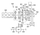
本発明の第1実施形態にかかる車両用駆動装置の概略構成図、
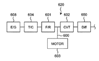
第1実施形態にかかる車両用駆動装置の動力経路ブロック図、
本発明の第1実施形態の第1変形例にかかる車両用駆動装置の概略構成図、
本発明の第1実施形態の第2変形例にかかる車両用駆動装置の概略構成図、
本発明の第1実施形態の第3変形例にかかる車両用駆動装置の概略構成図、
本発明の第1実施形態の第4変形例にかかる車両用駆動装置の概略構成図。
以下に、本発明にかかる実施の形態を図面に基づいて詳細に説明する。
(第1実施形態)
本発明の第1実施形態にかかるハイブリッド駆動装置620は、変速機の上流側に前後進切替機構を配置するタイプの自動変速機を有する車両において、前後進切替機構の出力側にモータ出力を入力可能とすることにより、少ない改造範囲でハイブリッド機能を付与し、車両燃費を向上するものである。
本発明の第1実施形態にかかるハイブリッド駆動装置620は、変速機の上流側に前後進切替機構を配置するタイプの自動変速機を有する車両において、前後進切替機構の出力側にモータ出力を入力可能とすることにより、少ない改造範囲でハイブリッド機能を付与し、車両燃費を向上するものである。
第1実施形態にかかるハイブリッド駆動装置620は、図1及び図2に示すように、例えばエンジン(E/G)608の下流側の発進装置(T/C、すなわち、トルクコンバータなど)604のさらに下流側に配置され、前後進切替機構(F/R)601と、変速機(CVTなど)602と、前後進切替機構601の出力側に入力経路600と、入力経路600に接続されるモータ603とで構成されている。変速機602は、一例としてCVTで構成されている。
前記前後進切替機構601は、摩擦クラッチ605と、摩擦ブレーキ606と、遊星歯車607とで構成されている。摩擦クラッチ605は、発進装置604の出力軸に連結された入力側部材605bと、入力側部材605bに接離する出力側部材605aとで構成されている。摩擦ブレーキ606は、摩擦クラッチ605の出力側部材605aに連結された入力側部材606bと、入力側部材606bに接離する出力側部材606aとで構成されている。
遊星歯車607は、サンギヤ610と、サンギヤ610と噛み合う複数のピニオンギヤ611と、ピニオンギヤ611と噛み合うリングギヤ612とで構成されている。複数のピニオンギヤ611のピニオンキャリア609には、摩擦クラッチ605の出力側部材605aが連結されている。
エンジン(E/G)608からの入力は、発進装置(T/C、すなわち、トルクコンバータなど)604を経由して、遊星歯車607のサンギヤ610に入力されている。発進装置604の一例としてはトルクコンバータである。
摩擦クラッチ605は、入力側部材605bがサンギヤ610に接続され、出力側部材605aがピニオンキャリア609を介してピニオンギヤ611に接続されている。
摩擦ブレーキ606は、入力側部材606bがピニオンギヤ611に接続され、出力側部材606aがハイブリッド駆動装置620のケース614に固定されている。
リングギヤ612は、変速機602の入力軸613に接続されている。
リングギヤ612の外周面には歯車612aを形成し、入力経路600としている。具体的には、リングギヤ612の外周面の歯車612aは、モータ603の出力軸630に固定された歯車631と噛み合っており、モータ603のトルクが、前後進切替機構601の出力側であるリングギヤ612に入力される。
なお、図1において、変速機602からの出力軸651には、歯車652が固定されている。歯車652は、差動装置(Diff)650の歯車653と噛み合っている。差動装置650には一対のドライブシャフト654が接続されている。
第1実施形態によれば、変速機602の上流側に前後進切替機構601を配置するタイプの自動変速機を有する車両において、前後進切替機構601の出力側にモータ出力を入力可能とする入力経路600を備えることにより、少ない改造範囲でハイブリッド機能を付与し、車両の走行性能と燃費とを向上することができる。すなわち、エンジン動力に加え、モータ603を補助動力として用いることで、エンジン出力を低減することができる。また、リングギヤ612に外歯612aを形成し、モータ603を別軸入力とすることで、既存の変速機の内部構造を大きく変更することなく、車両の電動化を実現することが出来る。また、変速機602の入力側にモータ603からのトルクを入力することで、モータ603が変速機602の変速比を利用し、運転領域を拡大することが可能で、車両燃費を向上させることができる。また、車両減速時には前後進切替機構601のクラッチ605及びブレーキ606を開放して、エンジン608からの出力を遮断することができる。これにより、エンジンフリクションロスを無くし、回生エネルギー量を増加することが可能である。
第1実施形態の第1変形例として、図3に示すように、前後進切替機構601の入力経路600としては、リングギヤ612の外周面が歯車612aの代わりにスプロケット612bで形成され、スプロケット612bがチェーン615を介してモータ603の出力軸630に接続されるようにしてもよい。このようにチェーン615を介する事により、モータ配置の自由度をより広くすることが可能となる。例えば、第1実施形態の様な歯車伝達では減速比によって軸間距離が決定されるため、モータ径方向寸法に対する制約となる懸念があるが、チェーンを介する事によって軸間距離に自由度ができ、このような懸念を解消する事ができる。
また、第2~第4変形例として、図4~図6に示すように、前後進切替機構601の入力経路600としては、リングギヤ612の側面、あるいは変速機602の入力軸613に配置されるようにしてもよい。
すなわち、図4では、リングギヤ612の側面に歯車612cが形成され、この歯車612cと、モータ603の出力軸630に固定された歯車631とが噛み合っており、モータ603のトルクが、前後進切替機構601の出力側であるリングギヤ612に入力される。このような構成とすることにより、第1変形例と同様に、モータ配置の自由度を広げ、モータ径方向寸法に対する制約を解消することができる。
図5では、変速機602の入力軸613に歯車616が固定され、この歯車616と、モータ603の出力軸630に固定された歯車631とが噛み合っており、モータ603のトルクが、変速機602の入力軸613に入力される。第1実施形態ではリングギヤ612の径方向寸法により歯車612aの歯数、すなわちモータ603の出力軸630と入力軸613の間の減速比が制約を受けるが、このような構成とすることにより、リングギヤ612の径方向寸法による制約を受けることなく、モータ603と入力軸613の間の減速比を決定する事ができる。
図6では、変速機602の入力軸613に補助遊星歯車617が固定され、この補助遊星歯車617にモータ603が組み込まれており、モータ603のトルクが、前後進切替機構601の出力側であるリングギヤ612に入力される。補助遊星歯車617は、サンギヤ618と、サンギヤ618と噛み合う複数のピニオンギヤ619と、ピニオンギヤ619と噛み合うリングギヤ627とで構成されている。複数のピニオンギヤ619のピニオンキャリア621には、摩擦ブレーキ622の入力側部材622aが連結されている。摩擦ブレーキ622は、入力側部材622aがピニオンギヤ619に接続され、出力側部材622bがハイブリッド駆動装置620のケース614に固定されている。リングギヤ627の外周面にはモータ603の回転子603aが固定され、固定子603bに対して回転してモータ603を構成する。このような構成では、モータ603と変速機602との間に補助遊星歯車617を追加する事により、さらにモータ603を高回転化して小型化する事ができる。また、走行中にモータ603が不要な場面では、ピニオンキャリア621の摩擦ブレーキ622を開放する事により、モータ603の回転を停止させ、モータ回転による損失を無くすことが可能である。
なお、前記様々な実施形態又は変形例のうちの任意の実施形態又は変形例を適宜組み合わせることにより、それぞれの有する効果を奏するようにすることができる。また、実施形態同士の組み合わせ又は実施例同士の組み合わせ又は実施形態と実施例との組み合わせが可能であると共に、異なる実施形態又は実施例の中の特徴同士の組み合わせも可能である。
本発明は、添付図面を参照しながら実施形態に関連して充分に記載されているが、この技術の熟練した人々にとっては種々の変形や修正は明白である。そのような変形や修正は、添付した請求の範囲による本発明の範囲から外れない限りにおいて、その中に含まれると理解されるべきである。
本発明にかかるハイブリッド駆動装置は、限られたスペースであっても、ハイブリッドシステムを構成することが可能であり、小型自動車を始めとする各種車両に有用である。
600 入力経路
601 前後進切替機構(F/R)
602 変速機(CVTなど)
603 モータ
603a 回転子
603b 固定子
604 発進装置
605 摩擦クラッチ
605a 摩擦クラッチの出力側部材
605b 摩擦クラッチの入力側部材
606 摩擦ブレーキ
606a 摩擦ブレーキの出力側部材
606b 摩擦ブレーキの入力側部材
607 遊星歯車
608 エンジン(E/G)
609 ピニオンキャリア
610 サンギヤ
611 ピニオンギヤ
612 リングギヤ
612a 歯車
612b スプロケット
612c 歯車
613 入力軸
614 ハイブリッド駆動装置のケース
615 チェーン
616 歯車
617 補助遊星歯車
618 サンギヤ
619 ピニオンギヤ
621 ピニオンキャリア
622 摩擦ブレーキ
622a 摩擦ブレーキの出力側部材
622b 摩擦ブレーキの入力側部材
620 ハイブリッド駆動装置
627 リングギヤ
630 出力軸
650 差動装置(Diff)
651 出力軸
652 歯車
653 歯車
654 ドライブシャフト
601 前後進切替機構(F/R)
602 変速機(CVTなど)
603 モータ
603a 回転子
603b 固定子
604 発進装置
605 摩擦クラッチ
605a 摩擦クラッチの出力側部材
605b 摩擦クラッチの入力側部材
606 摩擦ブレーキ
606a 摩擦ブレーキの出力側部材
606b 摩擦ブレーキの入力側部材
607 遊星歯車
608 エンジン(E/G)
609 ピニオンキャリア
610 サンギヤ
611 ピニオンギヤ
612 リングギヤ
612a 歯車
612b スプロケット
612c 歯車
613 入力軸
614 ハイブリッド駆動装置のケース
615 チェーン
616 歯車
617 補助遊星歯車
618 サンギヤ
619 ピニオンギヤ
621 ピニオンキャリア
622 摩擦ブレーキ
622a 摩擦ブレーキの出力側部材
622b 摩擦ブレーキの入力側部材
620 ハイブリッド駆動装置
627 リングギヤ
630 出力軸
650 差動装置(Diff)
651 出力軸
652 歯車
653 歯車
654 ドライブシャフト
Claims (9)
- 前後進切替機構と、変速機と、前記前後進切替機構の出力側に配置された入力経路と、前記入力経路に接続されるモータとで構成される、ハイブリッド駆動装置。
- 前記前後進切替機構は、摩擦クラッチと、摩擦ブレーキと、遊星歯車とで構成され、
前記遊星歯車は、サンギヤと、前記サンギヤと噛み合うピニオンギヤと、前記ピニオンギヤと噛み合うリングギヤとで構成され、
エンジン入力は、発進装置を経由して前記遊星歯車の前記サンギヤに入力され、
前記摩擦クラッチは、前記サンギヤと前記ピニオンギヤとに接続され、
前記摩擦ブレーキは、前記ピニオンギヤに接続され、前記リングギヤは前記変速機の入力軸に接続される、請求項1に記載のハイブリッド駆動装置。 - 前記発進装置はトルクコンバータである、請求項2に記載のハイブリッド駆動装置。
- 前記遊星歯車の前記リングギヤの外周面に歯車を形成し、前記入力経路とする、請求項2に記載のハイブリッド駆動装置。
- 前記入力経路に対して、前記リングギヤの前記外周面の前記歯車と噛み合う歯車を経由して、前記モータの出力軸が接続される、請求項4に記載のハイブリッド駆動装置。
- 前記入力経路は、前記リングギヤの外周面がスプロケットで形成され、チェーンを介して前記モータの出力軸が接続されている、請求項2に記載のハイブリッド駆動装置。
- 前記入力経路は、前記リングギヤの側面に配置されている、請求項2に記載のハイブリッド駆動装置。
- 前記入力経路は、前記変速機の入力軸に配置されている、請求項1に記載のハイブリッド駆動装置。
- 前記入力経路は、前記変速機の入力軸に配置され、前記入力経路と前記モータの間に補助遊星歯車と、摩擦ブレーキとが配置され、
前記補助遊星歯車は、サンギヤと、前記サンギヤと噛み合うピニオンギヤと、前記ピニオンギヤと噛み合うリングギヤとで構成され、
モータ入力は、前記補助遊星歯車の前記リングギヤに入力され、
前記摩擦ブレーキは、前記ピニオンギヤに接続され、前記サンギヤは、前記変速機の前記入力軸に接続される、請求項1に記載のハイブリッド駆動装置。
Priority Applications (3)
| Application Number | Priority Date | Filing Date | Title |
|---|---|---|---|
| DE112016004784.3T DE112016004784T5 (de) | 2015-10-20 | 2016-10-13 | Hybrid-Antriebsstrang |
| CN201680060741.6A CN108136887A (zh) | 2015-10-20 | 2016-10-13 | 混合动力驱动装置 |
| US15/769,123 US10788110B2 (en) | 2015-10-20 | 2016-10-13 | Hybrid driving apparatus |
Applications Claiming Priority (4)
| Application Number | Priority Date | Filing Date | Title |
|---|---|---|---|
| JP2015206491 | 2015-10-20 | ||
| JP2015-206491 | 2015-10-20 | ||
| JP2016-183444 | 2016-09-20 | ||
| JP2016183444A JP6759027B2 (ja) | 2015-10-20 | 2016-09-20 | ハイブリッド駆動装置 |
Publications (1)
| Publication Number | Publication Date |
|---|---|
| WO2017069042A1 true WO2017069042A1 (ja) | 2017-04-27 |
Family
ID=58557331
Family Applications (1)
| Application Number | Title | Priority Date | Filing Date |
|---|---|---|---|
| PCT/JP2016/080396 Ceased WO2017069042A1 (ja) | 2015-10-20 | 2016-10-13 | ハイブリッド駆動装置 |
Country Status (1)
| Country | Link |
|---|---|
| WO (1) | WO2017069042A1 (ja) |
Cited By (2)
| Publication number | Priority date | Publication date | Assignee | Title |
|---|---|---|---|---|
| WO2020057712A1 (en) * | 2018-09-18 | 2020-03-26 | Robert Bosch Gmbh | Powertrain with a continuously variable transmission for an electric vehicle and method for operating an electric vehicle |
| US11511730B2 (en) * | 2018-02-15 | 2022-11-29 | Hitachi Astemo, Ltd. | Drive device, and vehicle |
Citations (7)
| Publication number | Priority date | Publication date | Assignee | Title |
|---|---|---|---|---|
| JPH11107798A (ja) * | 1997-10-08 | 1999-04-20 | Aisin Aw Co Ltd | ハイブリッド駆動装置 |
| JP2003120800A (ja) * | 2001-10-19 | 2003-04-23 | Honda Motor Co Ltd | 動力伝達装置 |
| JP2006327570A (ja) * | 2005-04-28 | 2006-12-07 | Toyota Central Res & Dev Lab Inc | 動力伝達システム |
| JP2008185070A (ja) * | 2007-01-26 | 2008-08-14 | Toyota Motor Corp | 車両用駆動装置の制御装置 |
| JP2011093345A (ja) * | 2009-10-27 | 2011-05-12 | Kawasaki Heavy Ind Ltd | 車両系建設機械及びその制御方法 |
| JP2015031312A (ja) * | 2013-07-31 | 2015-02-16 | ダイハツ工業株式会社 | 動力伝達機構 |
| JP2015067227A (ja) * | 2013-09-30 | 2015-04-13 | ダイハツ工業株式会社 | 動力伝達機構 |
-
2016
- 2016-10-13 WO PCT/JP2016/080396 patent/WO2017069042A1/ja not_active Ceased
Patent Citations (7)
| Publication number | Priority date | Publication date | Assignee | Title |
|---|---|---|---|---|
| JPH11107798A (ja) * | 1997-10-08 | 1999-04-20 | Aisin Aw Co Ltd | ハイブリッド駆動装置 |
| JP2003120800A (ja) * | 2001-10-19 | 2003-04-23 | Honda Motor Co Ltd | 動力伝達装置 |
| JP2006327570A (ja) * | 2005-04-28 | 2006-12-07 | Toyota Central Res & Dev Lab Inc | 動力伝達システム |
| JP2008185070A (ja) * | 2007-01-26 | 2008-08-14 | Toyota Motor Corp | 車両用駆動装置の制御装置 |
| JP2011093345A (ja) * | 2009-10-27 | 2011-05-12 | Kawasaki Heavy Ind Ltd | 車両系建設機械及びその制御方法 |
| JP2015031312A (ja) * | 2013-07-31 | 2015-02-16 | ダイハツ工業株式会社 | 動力伝達機構 |
| JP2015067227A (ja) * | 2013-09-30 | 2015-04-13 | ダイハツ工業株式会社 | 動力伝達機構 |
Cited By (3)
| Publication number | Priority date | Publication date | Assignee | Title |
|---|---|---|---|---|
| US11511730B2 (en) * | 2018-02-15 | 2022-11-29 | Hitachi Astemo, Ltd. | Drive device, and vehicle |
| WO2020057712A1 (en) * | 2018-09-18 | 2020-03-26 | Robert Bosch Gmbh | Powertrain with a continuously variable transmission for an electric vehicle and method for operating an electric vehicle |
| WO2020057779A1 (en) * | 2018-09-18 | 2020-03-26 | Robert Bosch Gmbh | Powertrain with a continuously variable transmission for an electric vehicle and method for operating such powertrain |
Similar Documents
| Publication | Publication Date | Title |
|---|---|---|
| JP6759027B2 (ja) | ハイブリッド駆動装置 | |
| US8887588B2 (en) | Transmission | |
| KR101847312B1 (ko) | 자동 변속기 | |
| CN104334925A (zh) | 车辆用动力传递装置 | |
| KR101416422B1 (ko) | 하이브리드 차량용 변속장치 | |
| WO2013176208A1 (ja) | 車両用動力伝達装置 | |
| KR101550610B1 (ko) | 하이브리드 차량용 변속장치 | |
| JP2010188795A (ja) | ハイブリッド車両の駆動装置 | |
| JP5835477B2 (ja) | 車両用動力伝達装置 | |
| JP2007186199A (ja) | ハイブリッド車両の動力伝達装置 | |
| JP2011122684A (ja) | 無段変速機 | |
| JP2010208417A (ja) | 無段変速機 | |
| JP6049123B2 (ja) | ハイブリッド車両の駆動装置 | |
| JP6078401B2 (ja) | 車両の駆動装置 | |
| WO2017069042A1 (ja) | ハイブリッド駆動装置 | |
| JP2010269717A (ja) | 車両の駆動装置 | |
| JP2015031312A (ja) | 動力伝達機構 | |
| JP4930267B2 (ja) | ハイブリッド車の駆動装置 | |
| CN108278337B (zh) | 双阶行星轮无限连续换档变速器 | |
| WO2013046362A1 (ja) | 無段変速機 | |
| CN114379359A (zh) | 用于机动车辆的传动机构及驱动系统 | |
| KR101584014B1 (ko) | 하이브리드 차량용 파워트레인 | |
| KR20150060061A (ko) | 차량의 하이브리드 변속기 | |
| KR101316426B1 (ko) | 차량용 무단 변속기의 후진 기어 구조 | |
| JP2017062012A (ja) | 車両用駆動装置 |
Legal Events
| Date | Code | Title | Description |
|---|---|---|---|
| 121 | Ep: the epo has been informed by wipo that ep was designated in this application |
Ref document number: 16857357 Country of ref document: EP Kind code of ref document: A1 |
|
| WWE | Wipo information: entry into national phase |
Ref document number: 15769123 Country of ref document: US |
|
| WWE | Wipo information: entry into national phase |
Ref document number: 112016004784 Country of ref document: DE |
|
| 122 | Ep: pct application non-entry in european phase |
Ref document number: 16857357 Country of ref document: EP Kind code of ref document: A1 |