WO2017065236A1 - 充填方法および充填装置 - Google Patents
充填方法および充填装置 Download PDFInfo
- Publication number
- WO2017065236A1 WO2017065236A1 PCT/JP2016/080437 JP2016080437W WO2017065236A1 WO 2017065236 A1 WO2017065236 A1 WO 2017065236A1 JP 2016080437 W JP2016080437 W JP 2016080437W WO 2017065236 A1 WO2017065236 A1 WO 2017065236A1
- Authority
- WO
- WIPO (PCT)
- Prior art keywords
- temperature
- thermosetting resin
- unit
- gas
- heating
- Prior art date
- Legal status (The legal status is an assumption and is not a legal conclusion. Google has not performed a legal analysis and makes no representation as to the accuracy of the status listed.)
- Ceased
Links
Images






Classifications
-
- H—ELECTRICITY
- H10—SEMICONDUCTOR DEVICES; ELECTRIC SOLID-STATE DEVICES NOT OTHERWISE PROVIDED FOR
- H10P—GENERIC PROCESSES OR APPARATUS FOR THE MANUFACTURE OR TREATMENT OF DEVICES COVERED BY CLASS H10
- H10P14/00—Formation of materials, e.g. in the shape of layers or pillars
- H10P14/60—Formation of materials, e.g. in the shape of layers or pillars of insulating materials
Definitions
- the present invention relates to a filling method and a filling device, and more particularly to a filling method and a filling device for filling a thermosetting resin in a fine space of a wafer. More preferably, the present invention relates to an insulating layer forming method and an insulating layer forming apparatus using a thermosetting resin.
- thermosetting resin in a fine space of a wafer
- a filling method for filling a thermosetting resin in a fine space of a wafer is known.
- Such a filling method for filling the fine space of the wafer with a thermosetting resin is disclosed in, for example, Japanese Patent No. 5330323.
- Japanese Patent No. 5330323 discloses a filling method for filling a fluid insulating material (thermosetting resin) into a via (fine space) provided in a wafer.
- a fluid insulating material thermosetting resin
- the fluid insulating material is cured in a state where a forced external force exceeding the atmospheric pressure is applied.
- the forced external force at least one of press pressure, injection pressure, rolling pressure, and centrifugal force is selected.
- thermosetting resin is a mixture containing a resin material and a solvent.
- the solvent is evaporated (transpiration) by heating the thermosetting resin.
- the crosslinking reaction is a need to improve.
- the filling method disclosed in Japanese Patent No. 5330323 discloses that the thermosetting resin is cured in a state where a forced external force exceeding the atmospheric pressure is applied, but the filling failure in the fine space is sufficiently suppressed.
- the yield there is a problem that it is difficult to improve the yield.
- the present invention has been made to solve the above-described problems, and an object of the present invention is to improve the yield by suppressing filling defects such as the generation of voids (bubbles) or voids in a fine space. It is an object of the present invention to provide a filling method and a filling device which can be used.
- a filling method is a filling method for filling a microscopic space provided in a substrate with a thermosetting resin, and the thermosetting resin supplied from the upper side of the substrate is filled with the processing chamber.
- Pressurizing step for pressurizing with gas from the surface exposed to the substrate, cooling step for cooling the gas for pressurizing the thermosetting resin, and heating step for heating the back surface of the substrate to which the thermosetting resin is supplied The cooling step and the heating step are performed with time overlap during the pressurizing step.
- the “fine space” means a fine groove having a width of 100 ⁇ m or less and a fine through hole and a non-through hole having a hole diameter of 100 ⁇ m or less formed on the wafer mainly by etching.
- the cooling step of cooling the gas for pressurizing the thermosetting resin and the heating step of heating the back surface of the surface supplied with the thermosetting resin among the substrates are provided.
- the cooling step and the heating step are performed with time overlap during the pressurizing step.
- the surface side where the thermosetting resin is exposed is pressurized with a cooled relatively low temperature gas, and the bottom side (back side) in the fine space is relatively heated to the bottom.
- Solvent evaporation and resin curing (crosslinking) can be performed from the side. Thereby, a solvent can be actively evaporated in order from the bottom part side rather than the surface side which thermosetting resin exposes.
- thermosetting resin is cured in order from the bottom side by heating on the bottom side while suppressing the surface side of the thermosetting resin from being cured (crosslinked) by pressurizing the surface side with a low temperature gas. can go.
- the size of the void can be reduced by the pressure, and an effect of pushing out the void to the uncured surface side of the thermosetting resin can be expected.
- the gas is maintained at a predetermined temperature lower than the heating temperature of the heating step, or has a predetermined temperature difference with respect to the heating temperature of the heating step. Cooled down. If comprised in this way, the temperature of gas can be controlled to the suitable temperature according to the thermosetting resin material with which it is filled. For example, by maintaining the gas temperature at a predetermined temperature lower than the evaporation temperature, solvent evaporation on the surface side of the thermosetting resin can be suppressed, and solvent evaporation and resin curing can proceed on the bottom side. Can do.
- the temperature of the gas is controlled to be lower than the heating temperature on the bottom side by a predetermined temperature difference, the temperature difference is reduced with respect to the reaction (solvent transpiration or curing) of the thermosetting resin on the bottom side.
- the reaction of the thermosetting resin on the surface side can proceed so as to be delayed by a corresponding time difference.
- the heating step includes a first heating stage in which the back surface of the substrate is heated to a first temperature to evaporate the solvent contained in the thermosetting resin, and the back surface of the substrate is the first. And a second heating stage in which the thermosetting resin is crosslinked by heating to a second temperature higher than the temperature, and the cooling step is performed at least overlapping with the first heating stage. If comprised in this way, the surface side cooling of a thermosetting resin can be performed in the 1st heating step which evaporates a solvent. As a result, the evaporation of the solvent from the bottom side and the replenishment of the resin from the surface side with high fluidity can be reliably performed, so that the occurrence of poor filling can be effectively suppressed.
- thermosetting resin is supplied onto the substrate and into the fine space so that the thermosetting resin becomes a film having a predetermined thickness on the substrate.
- the entire surface of the film-like thermosetting resin exposed in the processing chamber is pressurized.
- thermosetting resin in the supplying step, after the thermosetting resin is supplied onto the substrate in a reduced pressure environment, a differential pressure filling is performed in which the thermosetting resin is filled into the fine space at a pressure higher than the pressure in the reduced pressure environment. If comprised in this way, a thermosetting resin can be effectively filled in micro space, suppressing generation
- a processing chamber capable of accommodating a substrate provided with a fine space, a gas is supplied into the processing chamber, and the thermosetting resin supplied from the upper side of the substrate is exposed in the processing chamber.
- a pressure unit that pressurizes with gas from the surface
- a cooling unit that cools the gas that pressurizes the thermosetting resin
- a heating unit that heats the back surface of the surface of the substrate to which the thermosetting resin is supplied
- gas cooling And a control unit that controls the cooling unit and the heating unit so that the heating of the substrate is performed in a time-overlapping manner during the pressing by the pressing unit.
- the cooling unit that cools the gas that pressurizes the thermosetting resin
- the heating unit that heats the back surface of the surface of the substrate to which the thermosetting resin is supplied
- a control unit that controls the cooling unit and the heating unit is provided so that the cooling and the heating of the substrate are performed in a time-overlapping manner during the pressing by the pressing unit.
- thermosetting resin capable of positively evaporating the solvent in order from the bottom side rather than the surface side from which the thermosetting resin is exposed is obtained.
- the volume decrease of the thermosetting resin on the bottom side can be efficiently replenished from the surface side with high fluidity in which solvent transpiration is suppressed, so that the generation of voids and the like can be suppressed.
- the surface side of the thermosetting resin can be cured (crosslinked) by pressurizing the surface side with a low-temperature gas, and can be cured sequentially from the bottom side by heating on the bottom side. A filling device is obtained.
- thermosetting resin can be cured in order from the bottom side in the pressurized state, so the size of the void can be reduced by the pressure, and the thermosetting The action which extrudes a void to the uncured surface side can also be expected.
- the processing chamber includes a substrate mounting table and a cover unit that covers the substrate mounted on the mounting table, and the cooling unit cools the cover unit to provide gas. It is configured to cool. If configured in this way, for example, compared with a configuration in which a pressurized gas is circulated between the processing chamber and the cooler and cooled, the gas can be cooled only by cooling the cover portion, Simplification of the device configuration and size reduction of the device can be achieved.
- the cooling unit includes a refrigerant pipe provided in the cover part and a refrigerant supply unit that supplies the refrigerant to the refrigerant pipe.
- the control unit preferably controls the cooling unit based on an output of a temperature measuring device that measures the temperature of the refrigerant. If comprised in this way, since the temperature of gas can be grasped
- a gas flow path for circulating gas between the processing chamber and the cooling section is further provided, and the pressurizing section circulates the gas in the gas flow path in a pressurized state.
- the cooling unit is configured to cool the gas circulating through the gas flow path. If comprised in this way, the gas which pressurizes thermosetting resin can be circulated in a gas flow path, and the circulating gas can be directly cooled by a cooling part. Thereby, since the temperature of gas can be controlled directly, the responsiveness of temperature control of gas can be improved.
- control unit controls the cooling unit based on the output of the temperature measuring device that measures the outlet temperature from the gas processing chamber in the gas flow path or the inlet temperature of the cooling unit. If comprised in this way, feedback control of gas temperature can be performed based on the temperature of the gas at the time of flowing in into a cooling part. As a result, precise control of the gas temperature is possible, so that the yield can be improved more effectively by suppressing poor filling of the thermosetting resin.
- the control unit controls the cooling unit based on the output of the temperature measuring device arranged to face the substrate mounted on the mounting table. If comprised in this way, the temperature of the gas which pressurizes a board
- a plurality of temperature measuring devices are provided, and the control unit controls the cooling unit according to the outputs of the plurality of temperature measuring devices. If comprised in this way, since a temperature change and a temperature gradient can be grasped
- the processing chamber includes a substrate mounting table and a cover unit that covers the substrate mounted on the mounting table, and the heating unit heats the mounting table.
- the back surface of the substrate is configured to be heated. If comprised in this way, since the back surface of a board
- the heating unit includes a heater built in the mounting table. If comprised in this way, compared with the structure which provides a heating part (heater) in the exterior of a mounting base, while being able to miniaturize an apparatus, the heat
- the present invention as described above, it is possible to suppress the filling failure such as the generation of voids (bubbles) or voids in the fine space and improve the yield.
- FIG. 6 is a schematic view showing a filling device according to first to sixth embodiments of the present invention.
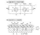
- FIG. 4A is a plan view showing a wafer before filling (during loading), and
- FIG. 4B is a cross-sectional view of the wafer taken along line 900-900 in FIG.
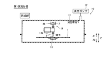
- It is the schematic diagram which showed the supply part of the filling apparatus by 1st Embodiment of this invention.
- It is the schematic diagram which showed the baking part of the filling apparatus by 1st Embodiment of this invention.
- It which showed temperature control in the heating process and cooling process of the filling method by 1st Embodiment of this invention.
- It is a figure for demonstrating the 1st part of the filling method by 1st Embodiment of this invention.
- FIG. 1 Schematic diagram showing a supply part of a filling device according to a fifth embodiment of the present invention
- B (C)
- C) (A ) Is a schematic longitudinal sectional view taken along line 920-920. It is the schematic diagram which showed the supply part of the filling apparatus by 6th Embodiment of this invention.
- the filling apparatus 100 fills and heats a thermosetting resin 3 (see FIG. 6) in a minute space 2 (see FIG. 2) such as an annular groove formed in the wafer 1 (see FIG. 2). It is a device to do.
- the wafer 1 is an example of the “substrate” in the claims. Instead of the wafer 1, a glass substrate 101 may be used.
- the filling apparatus 100 includes a supply unit 10, a baking unit 20, a peeling unit 30, a residue removal / polishing unit 40, and a cleaning / drying unit 50 as a wafer processing unit.
- the filling apparatus 100 further includes a carry-in / carry-out unit 60 that carries the wafer 1 that has undergone the previous process into the filling apparatus 100 and carries the wafer 1 that has been filled and baked out of the filling apparatus 100. I have.
- the filling apparatus 100 further includes a transport unit 70 that transports the wafer 1 to each wafer processing unit and the loading / unloading unit 60 by the robot arm 70a.
- the wafer 1 carried into the filling apparatus 100 by the carry-in / carry-out unit 60 is supplied by the transport unit 70 to the supply unit 10, the baking unit 20, the peeling unit 30, the residue removal / polishing unit 40, and the cleaning / polishing unit 40.
- the drying unit 50 is conveyed in this order. Thereby, the formation surface 1a of the fine space 2 of the wafer 1 is smoothed in a state where the hardened resin 3b (see FIG. 6) is filled in the fine space 2 of the wafer 1. Then, the wafer 1 is unloaded from the filling apparatus 100 by the loading / unloading unit 60, and a post-process or the like is performed.
- the wafer 1 is made of a general semiconductor material such as silicon. Further, the wafer 1 has a substantially circular shape having a diameter of, for example, about 200 mm when viewed in plan, and a plurality of chips can be cut out. Further, as shown in FIG. 2, the wafer 1 is carried into the filling apparatus 100 (see FIG. 1) in a state where a plurality of fine spaces 2 are formed by the etching process in the previous process. Here, approximately 1 million fine spaces 2 are formed in the wafer 1.
- the fine space 2 is an annular groove having an opening 2a, an inner surface 2b, and a bottom 2c, and a horizontal width W1 perpendicular to the thickness direction is about 100 ⁇ m or less.
- the depth L1 in the thickness direction of the fine space 2 depends on the width W1 so that the aspect ratio (L1 / W1) between the depth L1 and the width W1 of the fine space 2 satisfies about 2 or more and about 20 or less. It is preferable to be determined.
- the width W1 of the fine space 2 is about 2 ⁇ m
- the mask 4 made of a photosensitive resin or the like provided during the etching process remains on the formation surface 1 a on the side where the opening 2 a of the fine space 2 is formed without being removed in the previous process. ing.
- the through hole 4a of the mask 4 and the fine space 2 are in communication.
- the thickness of the mask 4 (the length in the thickness direction of the through hole 4a of the mask 4) t1 is appropriately adjusted according to the width W1 and depth L1 of the fine space 2 provided by the etching process and the aperture ratio of the fine space 2.
- the mask 4 is composed of NMP (N-methylpyrrolidine), a mixture of DMSO (dimethylsulfoxide) and KOH (potassium hydroxide), a mixture of DMSO and MEA (monomethanolamine), AZ100 REMOVER manufactured by CLAEIANT, etc. It can be peeled off from the wafer 1 using a general release agent. The wafer 1 with the mask 4 removed may be carried into the filling apparatus 100. In this case, the filling device 100 does not require the step of peeling the mask 4, and thus the peeling portion 30 may not be provided.
- the supply unit 10 is a so-called vacuum spin coater. That is, as shown in FIG. 3, the supply unit 10 includes a processing chamber 11 having an external appearance, a vacuum pump 12 for reducing the pressure in the processing chamber 11, and a wafer support disposed in the processing chamber 11. Part 13 and material dropping part 14 are included.
- the processing chamber 11 is configured to be openable and closable, and by driving the vacuum pump 12, the internal space can be brought into a reduced pressure environment of about 100 Pa or higher and lower than atmospheric pressure.
- the wafer support unit 13 can rotate the mounted wafer 1 in a horizontal direction orthogonal to the Z direction (vertical direction).
- the material dropping unit 14 includes a dropping nozzle 14a and a storage unit 14b in which the thermosetting resin 3 is stored.
- the dropping nozzle 14 a has a function of dropping the thermosetting resin 3 on the central portion of the wafer 1.
- the thermosetting resin 3 is, for example, a resin (binder) that is crosslinked and cured at a processing temperature higher than normal temperature and about 250 ° C. or lower as an insulating material.
- the thermosetting resin 3 include a fluororesin, a polyimide resin, a phenol resin, a silicon resin, and an epoxy resin.
- AL-X2000 series such as AL-X2003 and AL-X2010 manufactured by Asahi Glass Co., Ltd. are applicable as the fluororesin.
- PIMEL (registered trademark) BM302 and BL301 manufactured by Asahi Kasei E-material Co., Ltd. are applicable as the polyimide resin.
- ELPAC registered trademark
- WPR1201 and WPR5100 manufactured by JSR Corporation are applicable.
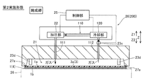
- the firing unit 20 is a so-called clean oven that can maintain the internal air cleanliness in a high state. As shown in FIG. 4, the firing unit 20 includes a processing chamber 21, a pressurizing unit 22, a cooling unit 23, a heating unit 24, and a control unit 25.
- the processing chamber 21 is configured to accommodate the wafer 1 provided with the fine space 2.
- the processing chamber 21 is an internal space formed by a mounting table 26 for the wafer 1 and a cover portion 27 that covers the wafer 1 mounted on the mounting table 26.
- the mounting table 26 and the cover part 27 have a cylindrical shape in appearance, and at least one of them is configured to be movable, and the processing chamber 21 can be opened and closed.
- the processing chamber 21 is configured to be hermetically sealed in a closed state.
- the hermetically sealed state may be configured by sealing between the mounting table 26 and the cover unit 27, or as shown in FIG. 4, the space between the wafer 1 on the mounting table 26 and the cover unit 27 is sealed. You may comprise by stopping. In the example of FIG.
- the cover portion 27 is provided with a sealing member such as an O-ring 27 a and is configured to maintain the inside of the processing chamber 21 in an airtight state.
- the mounting table 26 and the cover part 27 are made of metal such as stainless steel (SUS), for example.
- the cover portion 27 may be formed of a metal having high thermal conductivity (such as aluminum or an aluminum alloy) in order to cool a gas described later.
- the pressurizing unit 22 is configured to supply gas into the processing chamber 21 and pressurize the thermosetting resin 3 supplied from the upper side of the wafer 1 with gas from the surface exposed in the processing chamber 21. ing.
- the pressurizing unit 22 is constituted by a pressurizer (pump), for example, and is connected to a gas reservoir (not shown).
- the pressurizing unit 22 is connected to the internal space of the processing chamber 21 through a gas pipe 27 b formed in the cover unit 27.
- the gas introduced into the processing chamber 21 by the pressurizing unit 22 is preferably an inert gas such as nitrogen gas.
- the pressurizing unit 22 can place the space of the processing chamber 21 in a high pressure environment higher than atmospheric pressure. Thereby, it is possible to pressurize the whole surface exposed from the wafer 1 into the processing chamber 21 out of the thermosetting resin 3 supplied onto the wafer 1 by the supply unit 10 with the gas.
- the cooling unit 23 is configured to cool the gas that pressurizes the thermosetting resin 3.
- the cooling unit 23 is configured to cool the gas by cooling the cover unit 27.
- the cooling part 23 includes a refrigerant pipe 27c provided in the cover part 27, and a refrigerant supply part 23a that supplies the refrigerant to the refrigerant pipe 27c.
- the refrigerant pipe 27 c is provided in the cover portion 27 along the internal space of the processing chamber 21.
- the refrigerant supply unit 23a is connected to the inlet of the refrigerant pipe 27c, and is configured by a pump that sends out the refrigerant.
- a liquid refrigerant such as water or oil can be used.
- the cooling part 23 cools the cover part 27 by allowing the refrigerant to pass through the refrigerant pipe 27 c, and the cover part 27 cools the gas supplied to the internal space of the processing chamber 21.
- the cooling unit 23 may be configured to circulate while cooling the refrigerant by the cooler 23b as shown in FIG. 4, or may be configured to discharge the refrigerant from the outlet of the refrigerant pipe 27c without circulating the refrigerant. Good.
- the heating unit 24 is configured to heat the back surface 1b (lower surface) of the surface (formation surface 1a) supplied with the thermosetting resin 3 in the wafer 1.
- the heating unit 24 can heat the back surface 1 b of the wafer 1 as long as it covers at least the formation region of the fine space 2 in the wafer 1.
- the heating unit 24 is configured to heat the back surface 1 b of the wafer 1 by heating the mounting table 26.
- the heating unit 24 includes a heater 24 a built in the mounting table 26.
- the heater 24a for example, a planar film heater or a tubular sheathed heater can be used.
- the heater 24a can raise the temperature of the wafer 1 to a temperature of about 250 ° C. or lower.
- a heat insulating material 24b may be provided on the opposite side of the heater 24a from the processing chamber 21 (wafer 1). In this case, the heating by the heater 24a can be performed more efficiently.
- the control unit 25 has a function of controlling the operation of each unit of the baking unit 20. That is, the control unit 25 opens / closes the processing chamber 21, turns on / off the gas supply by the pressurizing unit 22, controls the pressure, controls cooling on / off by the cooling unit 23 and controls the cooling temperature, and heats by the heating unit 24 (heater 24 a). On / off and heating temperature control. In the first embodiment, the control unit 25 performs the cooling of the gas and the heating of the wafer 1 in a time-overlapping manner during the pressurization by the pressurization unit 22. And is configured to control. The control unit 25 may be a control unit that controls the entire filling apparatus 100 or may be a dedicated control unit for controlling the baking unit 20.
- the cooling unit 23 includes a temperature sensor 23c that measures the temperature of the refrigerant.
- the control unit 25 is configured to control the cooling unit 23 based on the output of the temperature sensor 23c.
- the temperature sensor 23c is an example of the “temperature measurement device” in the claims. In the configuration example of FIG. 4, the temperature sensor 23c is arranged at the outlet of the refrigerant pipe 27c, and the control unit 25 controls the cooling unit 23 based on the outlet temperature of the refrigerant pipe 27c.
- a plurality of temperature sensors 23c may be provided at a plurality of locations other than the outlet portion, such as the inlet portion of the refrigerant pipe 27c. In that case, the control part 25 controls the cooling part 23 according to the output of each temperature sensor 23c.
- the heating unit 24 includes a temperature sensor 24c that measures the heat generation temperature. Based on the measurement results of these temperature sensors 23c and 24c, the control unit 25 brings the gas temperature (refrigerant outlet temperature) and the heating temperature of the back surface 1b of the wafer 1 (heater 24a temperature) close to the desired target temperatures, respectively. It is configured to perform feedback control. The details of the temperature control in the firing step of FIG. 5 will be described later.
- the mask 4 (see FIG. 2B) on the wafer 1 is removed using a peeling agent.
- the peeling unit 30 may not be provided.
- the formation surface 1a (see FIG. 2B) of the wafer 1 is polished by mechanical polishing such as CMP (chemical mechanical polishing) or polisher.
- the cleaning / drying unit 50 is a general spin cleaning machine. The cleaning / drying unit 50 cleans the entire formation surface 1 a of the wafer 1 by dropping pure water while rotating the wafer 1. Thereafter, the cleaning / drying unit 50 rotates the wafer 1 at a high speed while blowing nitrogen, whereby the formation surface 1a of the wafer 1 is uniformly dried.
- the wafer 1 loaded by the loading / unloading unit 60 is transferred into the processing chamber 11 of the supply unit 10 by the transfer unit 70.
- the supply unit 10 supplies the thermosetting resin 3 on the wafer 1 and in the minute space 2 so that the thermosetting resin 3 forms a film having a predetermined thickness on the wafer 1 prior to the processing step by the baking unit 20.
- the supply process is performed.
- the supply step is a differential pressure that fills the thermosetting resin 3 in the microspace 2 with a pressure higher than the pressure in the reduced pressure environment. It is a process of filling.
- the supply process includes a decompression process, a contact process, and a filling process.
- the wafer 1 is placed at a predetermined position of the wafer support unit 13 (see FIG. 3) so that the formation surface 1a becomes the upper surface (the surface on the Z1 side). Then, as shown in FIG. 3, the inside of the processing chamber 11 is brought into an airtight state with the wafer 1 stored in the processing chamber 11. Then, the inside of the processing chamber 11 is made into a reduced pressure environment using the vacuum pump 12 (depressurization step). Thereby, the pressure in the fine space 2 of the wafer 1 is also reduced.
- the decompression environment in the process chamber 11 should just be a decompression environment of about 100 Pa or more and about 100 kPa or less.
- the reduced pressure (low pressure) of about 100 Pa or more and about 100 kPa or less is a reduced pressure environment corresponding to the low vacuum region described in JIS Z 8126-1 Vacuum Technology-Terminology.
- thermosetting resin 3 is brought into contact with the mask 4 while rotating the wafer 1.
- the thermosetting resin 3 is dropped onto the mask 4 from the formation surface 1a side (Z1 side) of the wafer 1 by the material dropping unit 14 while rotating the wafer 1 at a low speed of about 500 rpm or less by the wafer support unit 13.
- the thermosetting resin 3 is expanded in a circular shape on the wafer 1 with the low-speed rotation.
- the wafer 1 is then rotated at a high speed from about 500 rpm to about 4500 rpm.
- the thermosetting resin 3 is applied on the wafer 1 in a uniform film shape with a predetermined film thickness according to the rotation speed.
- the thermosetting resin 3 is applied by spin coating to the surface of the wafer 1 (the inner surface 2b of the minute space 2) (contact process).
- the thickness of the thermosetting resin 3 applied on the mask 4 by spin coating (distance in the thickness direction from the liquid surface 3a opposite to the wafer 1 of the thermosetting resin 3 to the upper surface 4b of the mask 4).
- t2 is determined by the depth L1 of the fine space 2 and the thickness t1 of the mask 4.
- the thickness t2 may be set according to the depth of the fine space 2, and is preferably about 50% to about twice the depth L1 of the fine space 2, for example.
- thermosetting resin 3 is applied to the surface of the wafer 1
- the reduced pressure inside the processing chamber 11 is opened to atmospheric pressure.
- a force (see FIG. 6) is exerted so that the entire surface of the liquid surface 3a opposite to the wafer 1 of the thermosetting resin 3 is pressed downward.
- the thermosetting resin 3 is filled in each of the approximately 1 million fine spaces 2 of the entire wafer 1 (filling step).
- the thermosetting resin 3 is also filled in the through holes 4 a of the mask 4 on the wafer 1.
- the inside of the processing chamber 11 is returned from the reduced pressure environment to a predetermined pressure that is higher than the reduced pressure environment and lower than the atmospheric pressure.
- differential pressure filling may be performed.
- the wafer 1 is transferred from the processing chamber 11 opened to the atmospheric pressure by the transfer unit 70 to the baking unit 20.
- the baking unit 20 is roughly a pressurizing step for pressurizing the entire surface exposed in the processing chamber 21 of the thermosetting resin 3 supplied on the wafer 1 with gas, and thermosetting.
- a cooling process for cooling the gas that pressurizes the resin 3 and a heating process for heating the back surface 1 b of the wafer 1 are performed.
- the wafer 1 is placed on the mounting table 26 in the processing chamber 21 of the baking unit 20.
- the processing chamber 21 is hermetically sealed while the wafer 1 is stored in the processing chamber 21.
- the pressurizing unit 22 introduces gas into the processing chamber 21 to make the inside of the processing chamber 21 a high pressure environment greater than atmospheric pressure and about 0.5 MPa or less. Thereby, in a pressurization process, the whole surface exposed in the process chamber 21 of the film-like thermosetting resin 3 is pressurized.
- the cooling unit 23 cools the gas that pressurizes the thermosetting resin 3 in the processing chamber 21. That is, the refrigerant is supplied from the refrigerant supply unit 23 a of the cooling unit 23 to the refrigerant pipe 27 c to cool the cover unit 27, and the gas is cooled through the cover unit 27. In the cooling step, the gas is cooled to maintain a predetermined temperature lower than the heating temperature of the heating step or to have a predetermined temperature difference with respect to the heating temperature of the heating step.
- the heating unit 24 heats the thermosetting resin 3 from the back surface 1b side of the wafer 1 (the bottom 2c side of the fine space 2). In the heating process, the heating unit 24 gradually raises the temperature of the heater 24a from the normal temperature to the processing temperature, and controls the processing time in each step, thereby baking the thermosetting resin 3 over the entire wafer 1. To do. As shown in FIG. 5, in the heating step, as the first heating stage, the backside 1b of the wafer 1 is heated to the first temperatures Tb1 and Tb2 to evaporate the solvent contained in the thermosetting resin 3, and 2 Including each stage of next baking.
- the heating step is a curing stage in which the back surface 1b of the wafer 1 is heated to a second temperature (Tc) higher than the first temperature (Tb1, Tb2) to crosslink the thermosetting resin 3 as a second heating stage.
- Tc second temperature
- the cooling process and the heating process are performed in a time-overlapping manner during the pressurizing process.
- the cooling process and the heating process may have the same implementation period, or there may be a portion that changes in time just by overlapping the implementation period. It is preferable that the cooling step is performed at least overlapping with the first heating stage (one or both of the primary baking and the secondary baking) in time. However, it does not exclude that the cooling process overlaps only with the second heating stage. Also, the cooling process may overlap with both the first heating stage and the second heating stage.
- each implementation period of the cooling process and the heating process may have a portion that does not overlap with the implementation period of the pressurization process.
- you may start a pressurization process after the start of a cooling process and a heating process.
- the time required for each temperature to reach the target temperature (processing temperature) by cooling the gas or heating the heater 24a is longer than the time required for increasing the gas pressure in the processing chamber 21 to the target pressure. Therefore, even if the pressurization process is started later, the gas pressure can be set to the target pressure until the cooling process and the heating process reach the target temperature (treatment temperature). Therefore, the start timing and end timing of the pressurizing step, the cooling step, and the heating step may be before or after each other or may be simultaneous.
- FIG. 5 shows an example in which the pressurizing step is performed over the entire period of FIG.
- two patterns of the cooling process A and the cooling process B will be described.
- the gas temperature in FIG. 5 is calculated
- the heater temperature (see the solid line) is raised from room temperature to about 100 ° C. at a constant rate of about 10 ° C. per minute. Then, the back surface 1b of the wafer 1 is maintained at about 100 ° C. for about 5 minutes (primary baking). In these primary bakings, removal of excess solvent is performed mainly to stabilize the shape of the thermosetting resin 3. Thereafter, the temperature of the back surface 1b of the wafer 1 is increased from about 100 ° C. to about 180 ° C. at a constant temperature increase rate of about 10 ° C. per minute. Then, the back surface 1b of the wafer 1 is maintained at about 180 ° C. for about 5 minutes (secondary baking).
- the solvent is completely removed in a state where the resin material of the thermosetting resin 3 is uniformly dispersed.
- the first temperature Tb1 of the primary baking is about 100 ° C.
- the first temperature Tb2 of the secondary baking is about 180 ° C.
- the temperature of the back surface 1b of the wafer 1 is increased from about 180 ° C. to about 250 ° C. (processing temperature) at a temperature increase rate of about 10 ° C. per minute.
- baking is performed by maintaining the back surface 1 b of the wafer 1 at a processing time of about 30 minutes to about 1 hour at about 250 ° C.
- the second curing temperature Tc is about 250 ° C.
- the thermosetting resin 3 is cured by the crosslinking reaction, so that the thermosetting resin 3 becomes a baked cured resin 3b (see FIG. 6C).
- ⁇ Cooling process A> In the cooling step A (refer to the two-dot chain line), in the primary baking, the temperature is raised from room temperature to about 100 ° C. so that the temperature rise rate (gradient) of the gas temperature is slower than the temperature rise rate of the heater temperature. Thereafter, the temperature is maintained at 100 ° C. (cooling is temporarily stopped). The gas temperature reaches 100 ° C. later than the heater temperature. Next, in secondary baking, cooling control is performed so that the gas temperature is maintained at a predetermined temperature (target temperature Tt). Therefore, the gas temperature is maintained substantially constant after reaching the temperature Tt.
- target temperature Tt target temperature
- the gas temperature is maintained at the predetermined temperature (target temperature Tt) even during the temperature increase of the heater in the cure (7 minutes up to about 250 ° C.).
- the cooling is stopped. For this reason, after the cooling is stopped, the gas temperature naturally rises to the processing temperature.
- the cooling process A is an example in which cooling control is performed such that the gas temperature is maintained at a predetermined temperature Tt lower than the heating temperature of the heating process.
- ⁇ Cooling process B> In the cooling process B (see broken line), the gas temperature control of the primary baking is the same as in the cooling process A. Next, after the secondary baking, the gas temperature is controlled to have a predetermined temperature difference Et with respect to the heater temperature. Therefore, the gas temperature is controlled to (heater temperature ⁇ Et) ° C. during and after the heater temperature is raised to 180 ° C. Similarly in the cure, the gas temperature is controlled to (heater temperature ⁇ Et) ° C. Even in the cooling step B, after the heater temperature reaches the processing temperature (about 250 ° C.), the cooling is stopped. Therefore, after the cooling is stopped, the gas temperature naturally rises to the processing temperature.
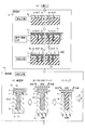
- a non-filling space 2d consisting of voids or voids remains slightly in the fine space 2 when mounted on the mounting table 26. Even so, in the first (second) baking stage of FIG. 6B, the non-filling space 2d is compressed to be small by heating from the bottom side and pressurization of the entire upper surface. Further, depending on the position, shape, etc. of the non-filling space 2d, it is pushed out together with the solvent to be evaporated.
- the transpiration of the solvent proceeds from the bottom side, and the thermosetting resin 3 on the upper surface side is cooled by the gas and remains highly fluid, so that the resin smoothly flows from the upper surface side according to the volume reduction on the bottom side. To be replenished. As a result, the remaining of the non-filling space 2d and the solvent is suppressed, and as shown in FIG. 6C, after the curing stage, the thermosetting resin 3 is cured with the cured resin 3b in a state where the filling failure is suppressed. And formed in the fine space 2.
- thermosetting resin 3 is filled not only in the fine space 2 but also in the through hole 4 a of the mask 4 on the wafer 1.
- the thermosetting resin 3 is filled with the volume decrease of the thermosetting resin 3 in the fine space 2 due to the evaporation of the solvent.
- It can replenish from the made thermosetting resin 3.
- the sum of the length t1 in the thickness direction of the through-hole 4a of the mask 4 and the thickness t2 of the thermosetting resin 3 is about 1 to 2 times the depth L1 of the fine space 2, A sufficient amount of the thermosetting resin 3 can be replenished to the fine space 2.
- a sufficient amount of the thermosetting resin 3 can be replenished to the minute space 2 by controlling the thickness (film thickness) t2 of the thermosetting resin 3 on the wafer 1. .
- the temperature and processing time (firing conditions) in the heating step can be appropriately adjusted to different firing conditions according to the material (containing component) of the thermosetting resin 3.
- the processing temperature (second temperature Tc) in the heating step may be set to a temperature of about 250 ° C. or less based on the properties of the thermosetting resin 3 and the processing time may be adjusted similarly.
- the processing temperature may be set to about 180 ° C. In this case, since the processing temperature is low, the temperature increase may be continued continuously in one or both of the primary baking and the secondary baking without providing a period for maintaining the temperature constant (first temperature). Tb1 and Tb2 may be changed continuously).
- the gas temperature and cooling time in the cooling step are also preferably set as appropriate based on the properties of the thermosetting resin 3 and the like.
- the solvent may not be completely removed in the first heating stage, but if the solvent remains in the second heating stage, voids are likely to be generated. Therefore, in order to suppress generation
- the predetermined time may be longer than the duration of the primary baking.
- the predetermined time for continuing the secondary baking is calculated or experimentally determined in consideration of the type of the thermosetting resin 3 to be filled and the volume of the fine space 2 (filling amount of the thermosetting resin 3). Can be set.
- the gas temperature may be maintained for a predetermined time in a state where the gas temperature is kept constant at the first temperature Tb2 of the secondary baking.
- thermosetting resin 3 is a fluororesin
- first temperature Tb1 of the primary baking is 90 ° C. and the second temperature Tc of the curing is 190 ° C.
- the thermosetting resin 3 is crosslinked at 180 ° C. or more. Begins. Therefore, the first temperature Tb2 of the secondary baking is set to a temperature between 90 ° C. after the completion of the primary baking and 170 ° C. before the start of crosslinking, and the temperature is sufficiently maintained for a predetermined time to perform the transpiration treatment. (Secondary baking) is performed. Thereby, the solvent can be completely evaporated.
- thermosetting resin 3 a case where a polybenzoxazole (PBO) resin is used is considered. Since polybenzoxazole (PBO) is solidified by a condensation reaction, it is unclear exactly from what degree of condensation starts, but the higher the temperature, the shorter the transpiration time. Therefore, when the first temperature Tb1 of the primary baking is 120 ° C. and the second temperature Tc of the curing is 230 ° C., the first temperature Tb2 of the secondary baking is changed from the first temperature Tb1 of the primary baking to the second temperature of the curing. By setting the temperature during Tc, for example, around 170 ° C. and maintaining the temperature sufficiently for a predetermined time, the solvent can be completely evaporated.
- PBO polybenzoxazole
- the pressurization process in the baking part 20 may pressurize by atmospheric pressure or a pressure lower than atmospheric pressure depending on the case. That is, when the inside of the filling device 100 is basically configured to be in a reduced pressure state lower than the atmospheric pressure, the pressurized state can be set even at a pressure lower than the atmospheric pressure or the atmospheric pressure. .
- the pressure value decreases (or rises) over time, is intermittently pressurized so as to include a pressurization stop period, or the pressure is periodically changed. It may be varied.
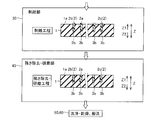
- the wafer 1 After opening the inside of the processing chamber 21 to atmospheric pressure, the wafer 1 is transferred from the baking unit 20 to the peeling unit 30 by the transfer unit 70. Then, as shown in FIG. 7, the mask 4 on the wafer 1 is removed using a peeling agent in the peeling portion 30 (peeling process). At that time, the baked and cured resin 3b on the mask 4 is also removed together with the mask 4. Thereafter, the wafer is transferred to the residue removal / polishing section 40 and the formation surface 1a of the wafer 1 is polished (residue removal / polishing step). As a result, the cured resin 3b that has been baked out of the fine space 2 is removed, and the formation surface 1a is smoothed. Then, the wafer 1 is transported to the cleaning / drying unit 50 and cleaned and dried (cleaning / drying step). Finally, the wafer 1 is unloaded by the loading / unloading unit 60.
- the cooling process which cools the gas which pressurizes the thermosetting resin 3, and the heating process which heats the back surface 1b of the wafer 1 are provided, and a cooling process and a heating process are performed.
- the process is repeated in time.
- the surface (liquid level 3a) side where the thermosetting resin 3 is exposed is pressurized with a cooled relatively low temperature gas, and the bottom 2c side (back side 1b side) in the fine space 2 is pressed.
- solvent evaporation and resin curing crosslinking
- thermosetting resin 3 it is possible to positively evaporate the solvent in order from the bottom 2c side rather than the surface side where the thermosetting resin 3 is exposed.
- the volume decrease of the thermosetting resin 3 on the bottom 2c side due to the transpiration of the solvent can be efficiently replenished from the liquid surface 3a side with high fluidity in which the transpiration of the solvent is suppressed. Can be suppressed.
- the bottom 2c side is heated by the bottom 2c side while suppressing the curing (crosslinking) of the liquid level 3a side of the thermosetting resin 3 due to the pressurization on the surface (liquid level 3a) side by the low temperature gas. It can be cured in order.
- the size of the non-filling space 2d can be reduced by pressure, and the thermosetting resin 3 is voided to the uncured liquid surface 3a side.
- the action of pushing out (non-filling space 2d) can also be expected.
- the filling method of the present embodiment it is possible to suppress the filling failure such as the generation of voids or voids in the fine space 2 and improve the yield.
- the cooling part 23 which cools the gas which pressurizes the thermosetting resin 3, and the back surface 1b of the surface to which the thermosetting resin 3 was supplied among the wafers 1 are heated.
- a control unit that controls the cooling unit 23 and the heating unit 24 so that the heating unit 24, gas cooling, and heating of the wafer 1 are performed in a time-overlapping manner during pressurization by the pressurization unit 22. 25.
- the surface side where the thermosetting resin 3 is exposed is pressurized with a relatively low temperature gas, and the bottom 2c side (back surface 1b side) in the micro space 2 is set to a relatively high temperature.
- a filling device 100 capable of performing a filling method for evaporating a solvent and curing a resin from the bottom 2c side can be obtained.
- the gas in the cooling step, is maintained at a predetermined temperature (temperature Tt) lower than the heating temperature in the heating step, or predetermined with respect to the heating temperature in the heating step.
- a predetermined temperature temperature Tt
- the temperature of gas can be controlled to the suitable temperature according to the thermosetting resin 3 material with which it is filled.
- solvent evaporation on the liquid surface 3a side of the thermosetting resin 3 is suppressed, and solvent evaporation and resin curing are performed on the bottom 2c side. Can be advanced.
- thermosetting resin 3 on the bottom 2c side solvent transpiration and curing
- the reaction of the thermosetting resin 3 on the liquid surface 3a side can proceed so as to be delayed by a time difference corresponding to the temperature difference.
- the cooling process instead of the configuration in which the gas temperature is controlled so as to correspond to the heating temperature of the heating process (maintained at the predetermined temperature Tt or controlled to maintain the temperature difference E), the cooling process is performed. Alternatively, the cooling may be continued without controlling the gas temperature.
- the gas temperature is not controlled, for example, if the cooling heat quantity is set too large, the temperature rise of the back surface 1b of the wafer 1 may be affected. That is, the gradient of the heater temperature in the heating process of FIG. 5 becomes gentle due to excessive cooling, and as a result, the processing time becomes longer as a whole, resulting in a decrease in processing efficiency. Therefore, in the cooling process, the gas temperature is controlled so as to correspond to the heating temperature of the heating process (maintained at the predetermined temperature Tt or controlled so as to maintain the temperature difference E). This is also effective in that the control of the temperature raising time and the control of solvent evaporation and resin curing can be optimized.
- the first heating for heating the back surface 1b of the wafer 1 to the first temperature (Tb1, Tb2) and evaporating the solvent contained in the thermosetting resin 3 is performed.
- the cooling process is performed at least overlapping with the first heating stage (primary baking and secondary baking) in time.
- the liquid level 3a side cooling of the thermosetting resin 3 can be performed.
- the transpiration of the solvent from the bottom 2c side and the replenishment of the resin from the liquid surface 3a side having high fluidity can be surely performed, so that the occurrence of poor filling can be effectively suppressed.
- thermosetting resin 3 prior to the pressurizing step, heat is applied on the wafer 1 and in the minute space 2 so that the thermosetting resin 3 forms a film having a predetermined thickness t2 on the wafer 1.
- a supply step for supplying the curable resin 3 is provided.
- the whole surface (entire surface of the liquid level 3a) exposed in the process chamber 21 of the film-like thermosetting resin 3 is pressurized.
- the volume decrease due to the transpiration and curing shrinkage of the thermosetting resin 3 is replenished from the film-like portion into the fine space 2.
- the supply step of supplying the thermosetting resin 3 is performed after supplying the thermosetting resin 3 onto the wafer 1 in a reduced pressure environment and then a pressure higher than the pressure in the reduced pressure environment.
- the differential pressure filling is performed by filling the micro space 2 with the thermosetting resin 3.
- the thermosetting resin 3 can be effectively filled in the fine space 2 while suppressing generation of voids or voids. Therefore, the pressurization step, the cooling step, and the heating step can be performed in a state where voids or voids are suppressed in advance, so that filling defects can be suppressed more effectively.
- the cooling unit 23 is configured to cool the gas by cooling the cover unit 27 configuring the processing chamber 21. Accordingly, for example, compared with a configuration in which a pressurized gas is circulated between the processing chamber 21 and the cooler to cool the gas, the gas can be cooled only by cooling the cover portion 27. And the size of the filling device 100 can be reduced.
- the cooling unit 23 including the refrigerant pipe 27c provided in the cover unit 27 and the refrigerant supply unit 23a that supplies the refrigerant to the refrigerant pipe 27c is provided.
- control unit 25 is configured to control the cooling unit 23 based on the output of the temperature sensor 23c that measures the temperature of the refrigerant.
- the heating unit 24 is configured to heat the back surface 1b of the wafer 1 by heating the mounting table 26 as described above. Thereby, since the back surface 1b of the wafer 1 can be heated via the mounting table 26, the structure which heats only the back surface 1b of the wafer 1 can be obtained easily.
- the heating unit 24 including the heater 24a built in the mounting table 26 is provided.
- the apparatus can be reduced in size as compared with the configuration in which the heating unit 24 (heater 24a) is provided outside the mounting table 26, and the heat of the heater 24a can be efficiently transferred to the wafer 1 (thermosetting resin 3). ).
- the cooling unit 120 is configured to cool the gas itself supplied to the processing chamber 21.
- the cooling unit 120 is installed together with the pressurizing unit 22 on a gas flow path 110 in a closed loop (circulation path) communicating with the processing chamber 21.
- the gas flow path 110 is configured to circulate gas between the processing chamber 21 and the cooling unit 120.
- the gas flow path 110 includes a pair of gas pipes 111 and 112 for circulation provided in the cover part 27, and gas is supplied from the pressurizing part 22 to the gas pipe 111, the processing chamber 21, and the gas pipe 112. Further, it is configured to be able to circulate back to the pressurizing unit 22 through the cooling unit 120.
- the cooling unit 120 is configured to cool the gas circulating through the gas flow path 110.
- the cooling unit 120 is configured as a cooler that cools the gas returning from the processing chamber 21 via the gas flow path 110.
- the gas may be cooled by water cooling as in the first embodiment, or may be cooled by a refrigeration cycle using a refrigerant.
- the cooled gas is sent to the pressurizing unit 22.
- the pressurizing unit 22 is configured to circulate the gas in the gas flow path 110 in a pressurized state.
- the pressurizing unit 22 is configured by, for example, a pressurizer (pump), as in the first embodiment, and maintains the entire gas flow path 110 including the processing chamber 21 in a high-pressure environment higher than atmospheric pressure. The gas is circulated as it is.
- the gas that pressurizes the thermosetting resin 3 is circulated in the closed-loop gas flow path 110 and is allowed to pass through the cooling unit 120 to directly cool the gas.
- the temperature sensor 23c is arranged to measure the gas outlet temperature (the outlet temperature of the processing chamber 21) or the inlet temperature of the cooling unit 120 in the gas pipe 112, and the control unit 25 is configured to The cooling unit 120 is controlled based on the output of the sensor 23c. That is, the control unit 25 controls the cooling unit 120 based on the gas outlet temperature from the processing chamber 21 or the inlet temperature of the cooling unit 120 in the gas flow path 110.
- the temperature sensor 23 d may be disposed in the processing chamber 21 so as to face the wafer 1 placed on the placement table 26.
- the temperature sensor 23d is an example of the “temperature measurement device” in the claims.
- the control unit 25 controls the cooling unit 120 based on the output of the temperature sensor 23d.
- the temperature sensor 23d is configured by a contact-type thermocouple, a non-contact-type thermometer (for example, an infrared radiation thermometer), or the like. When the temperature sensor 23d is configured by a thermocouple, the temperature sensor 23d directly measures the gas temperature in the vicinity of the surface of the wafer 1 (the liquid surface 3a of the thermosetting resin 3).
- the temperature sensor 23 d When the temperature sensor 23 d is configured by a non-contact type thermometer, the temperature sensor 23 d measures the temperature of the thermosetting resin 3 (liquid level 3 a) supplied to the surface of the wafer 1. Accordingly, the control unit 25 controls the cooling unit 120 based on the gas temperature in the vicinity of the wafer 1 in the processing chamber 21 or the surface temperature of the thermosetting resin 3.
- a configuration in which the surface temperature of the thermosetting resin 3 is acquired using a non-contact type thermometer is preferable because the temperature can be adjusted most accurately because the temperature to be controlled can be directly acquired.
- the control unit 25 controls the cooling unit 120 according to the outputs of the plurality of temperature sensors 23d.
- FIG. 8 shows both the temperature sensor 23c and the temperature sensor 23d, but only one of the temperature sensor 23c and the temperature sensor 23d may be provided.
- the control unit 25 may control the cooling unit 120 based on the output of either or both of the temperature sensor 23c and the temperature sensor 23d.
- the liquid surface 3a side where the thermosetting resin 3 is exposed is pressurized with a relatively low temperature gas in a pressurized environment, and the bottom portion in the fine space 2 is obtained. Since the solvent can be evaporated and the resin can be cured from the bottom 2c side by setting the 2c side (the back surface 1b side) to a relatively high temperature, filling defects such as voids or voids in the fine space 2 can be suppressed. Yield can be improved.
- the pressurization part 22 is comprised so that the gas in the gas flow path 110 may be circulated in a pressurized state, and the cooling part 120 is passed through the gas flow path 110. It is configured to cool the circulating gas.
- the gas which pressurizes the thermosetting resin 3 can be circulated in the gas flow path 110, and the circulating gas can be directly cooled by the cooling unit 120.
- the temperature of the gas can be directly controlled, so that the responsiveness of the temperature control of the gas can be improved.
- the cooling unit 120 is controlled based on the output of the temperature sensor 23c that measures the outlet temperature of the gas from the processing chamber 21 or the inlet temperature of the cooling unit 120 in the gas flow path 110.
- the control unit 25 is configured to control. Thereby, feedback control of gas temperature can be performed based on the temperature of the gas when flowing into the cooling unit 120. As a result, it becomes possible to precisely control the gas temperature, and it is possible to more effectively suppress defective filling of the thermosetting resin 3 and improve the yield.
- the control is performed so as to control the cooling unit 120 based on the output of the temperature sensor 23d disposed so as to face the wafer 1 placed on the placement table 26.
- Part 25 is configured.
- the temperature of the gas for pressurizing the wafer 1 or the temperature of the thermosetting resin 3 is measured in the vicinity of the surface of the wafer 1, and feedback control based on the measured temperature can be performed.
- the gas temperature in the vicinity of the thermosetting resin 3 can be controlled more precisely, the filling failure of the thermosetting resin 3 can be suppressed more effectively and the yield can be improved.
- a plurality of temperature sensors 23d are provided, and the control unit 25 is configured to control the cooling unit 120 according to the outputs of the plurality of temperature sensors 23d.
- gas temperature or surface temperature of the thermosetting resin 3
- the gas temperature can be controlled more precisely.
- the temperature sensors 23 d are provided at a plurality of locations in the processing chamber 21, it is possible to grasp the temperature distribution (temperature unevenness) generated due to gas stagnation in the processing chamber 21.
- the gas temperature can be controlled in consideration of the temperature distribution inside.
- the heating unit 210 of the filling device 300 includes a heater 211 provided outside the mounting table 26.
- the heater 211 is provided adjacent to the lower surface of the mounting table 26 (the surface opposite to the wafer 1).
- the heating unit 210 is configured to heat the thermosetting resin 3 on the wafer 1 from the back surface 1 b side via the mounting table 26 by heating the lower surface of the mounting table 26.
- a flat film heater can be used as the heater 211, but since the heater 211 is disposed outside the mounting table 26, any heater may be used.
- the liquid surface 3a side where the thermosetting resin 3 is exposed is pressurized with a relatively low temperature gas in a pressurized environment, and the bottom portion in the fine space 2 is pressed. Since the solvent can be evaporated and the resin can be cured from the bottom 2c side by setting the 2c side (the back surface 1b side) to a relatively high temperature, filling defects such as voids or voids in the fine space 2 can be suppressed. Yield can be improved.
- the configuration (structure) of the mounting table 26 and the heating unit 210 can be simplified by providing the heating unit 210 including the heater 211 provided outside the mounting table 26.
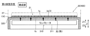
- the heating unit 310 of the filling device 400 is configured to directly heat the back surface 1 b of the wafer 1 placed on the placement table 320.
- the heating unit 310 includes a lamp heater 311 that irradiates light (heat rays) to the back surface 1 b of the wafer 1 through the translucent part of the mounting table 320.
- the lamp heater 311 is housed (incorporated) inside a hollow mounting table 320.
- the mounting table 320 is made of a light-transmitting material such as glass. That is, the entire mounting table 320 is a translucent part. Thereby, most of the light from the lamp heater 311 passes through the mounting table 320 and is absorbed by the back surface 1 b of the wafer 1.
- the lamp heater 311 is an example of the “heater” in the claims.
- the liquid surface 3a side where the thermosetting resin 3 is exposed is pressurized with a relatively low temperature gas in a pressurized environment, and the bottom portion in the micro space 2 is obtained. Since the solvent can be evaporated and the resin can be cured from the bottom 2c side by setting the 2c side (the back surface 1b side) to a relatively high temperature, filling defects such as voids or voids in the fine space 2 can be suppressed. Yield can be improved.
- a light transmitting part is provided on the mounting table 320, and the back surface 1 b of the wafer 1 placed on the mounting table 320 is heated by the light transmitted through the light transmitting part in the heating unit 310.
- a lamp heater 311 is provided.
- the mounting table 330 is made of a non-translucent metal material such as stainless steel.
- the mounting table 330 has a hollow shape in which the lamp heater 311 is disposed, and is formed with a through hole 331 penetrating the upper surface (mounting surface) in the vertical direction.
- the through-hole 331 is a circular hole formed with a diameter corresponding to the size of the wafer 1 (the size of the heating region of the wafer 1) placed on the mounting table 330.
- a window member 332 formed of a light-transmitting material such as glass is fitted in the through hole 331 in an airtight state.
- the light (heat rays) from the lamp heater 311 passes through the window member 332 of the through hole 331 and is irradiated on the back surface of the wafer 1.
- thermosetting resin 3 is applied to the wafer 1 using a spread (application member) 411 in the supply unit 410.
- an example in which the thermosetting resin 3 is applied to the wafer 1 using a spread (application member) 411 in the supply unit 410 will be described.
- an example in which the thermosetting resin 3 is applied to the wafer 1 using a spread (application member) 411 in the supply unit 410 will be described.
- an example in which the thermosetting resin 3 is applied to the wafer 1 using a spread (application member) 411 in the supply unit 410 will be described.
- an example in which the thermosetting resin 3 is applied to the wafer 1 using a spread (application member) 411 in the supply unit 410 will be described.
- an example in which the thermosetting resin 3 is applied to the wafer 1 using a spread (application member) 411 in the supply unit 410 will be described.
- an example in which the thermosetting resin 3 is applied to the wafer 1 using a spread (application member) 411 in the supply unit 410 will be
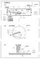
- the supply unit 410 of the filling apparatus 500 includes a processing chamber 11, a vacuum pump 12, a wafer support unit 13 and a spread 411 disposed in the processing chamber 11. Is included.
- the spread 411 spreads the thermosetting resin 3 supplied to the center of the surface of the wafer 1 on the upper surface of the wafer 1 with a certain film thickness.
- the spread 411 is attached to a lower surface portion on one end side of the arm portion 412, and is supported by a shaft portion 413 connected to the other end side of the arm portion 412.
- the spread 411 has, for example, a shape that extends linearly slightly longer than the radius of the wafer 1 and is disposed along the horizontal direction.
- the arm portion 412 extends in the horizontal direction, and one end of the arm portion 412 is disposed at a position above the wafer 1 held by the wafer support portion 13, and the other end of the arm portion 412 is at a radially outer position of the wafer 1. It has a predetermined length to be arranged.
- the shaft portion 413 extends in the vertical direction, and is connected to the vicinity of the other end of the arm portion 412. The shaft portion 413 extends to the outside of the processing chamber 11 while maintaining hermeticity by a seal structure (not shown), and is supported by a driving unit 414 disposed at the lower outside of the processing chamber 11.
- the drive unit 414 includes a rotation mechanism 414a that rotates the shaft portion 413 around the central axis in the vertical direction, and a lifting mechanism 413b that drives the shaft portion 413 to move up and down.
- the spread 411 can rotate in the R direction around the shaft portion 413 in the horizontal plane (on the upper surface of the wafer 1) as shown in FIG. It is configured.
- the spread 411 is configured to be movable to a position passing through the center of the wafer 1 and a position outside the outer periphery of the wafer 1 in plan view (see FIG. 12B).
- the drive unit 414 drives the shaft unit 413 to move up and down
- the spread 411 is configured to be movable up and down in a direction close to the wafer 1 and a direction away from the wafer 1.
- the spread 411 has a wafer 1 side tip (lower end) on the upper surface of the wafer 1 held by the wafer support 13 (formation surface 1a or upper surface 4b of the mask 4). On the other hand, they are arranged so as to be separated by a predetermined interval in the vertical direction. The distance between the tip of the spread 411 and the upper surface of the wafer 1 corresponds to the thickness t2 of the thermosetting resin 3.
- the drive part 414 can control the film thickness of the thermosetting resin 3 by controlling this distance by raising and lowering the spread 411 (shaft part 413).
- the supply unit 410 moves the spread 411 from the center of the wafer 1 along the R direction to the outer peripheral direction (see FIG. 12B) while rotating the wafer 1 at a low speed, thereby transferring the thermosetting resin 3 to the wafer 1. It is configured to be applied (spread).
- thermosetting resin 3 is supplied onto the wafer 1 by a predetermined amount used for one wafer 1 by a material supply member (not shown).
- the wafer 1 is rotated at a low speed at a rotation speed of about 1 rpm to about 60 rpm.
- the spread 411 moves in the outer peripheral direction from the center of the wafer 1, so that the surplus portion of the thermosetting resin 3 exceeding the distance between the tip (lower end) of the spread 411 and the upper surface of the wafer 1 is caused by the spread 411.
- the thermosetting resin 3 is formed on the entire surface of the wafer 1 with a constant film thickness.
- thermosetting resin 3 becomes a film having a predetermined thickness t ⁇ b> 2 on the wafer 1.
- the thermosetting resin 3 is filled with a differential pressure by performing the pressure reducing step and the filling step before and after the contact step.
- the spread 411 has an inclined surface 411a (see FIG. 12C) inclined toward the opposite side to the S direction in which the wafer 1 rotates with respect to the spread 411. Due to the inclined surface 411 a, the excess thermosetting resin 3 scraped off rotates along the inclined surface 411 a into a lump (columnar shape), and a certain film thickness is formed on the surface of the wafer 1 by the movement of the spread 411. I will do it. In addition, you may comprise the inclined surface 411a because flat plate-like spread 411 itself inclines.
- the structure of the wafer 1, the characteristics of the thermosetting resin 3, and other configurations of the filling device 500 in the fifth embodiment are the same as those in the first embodiment.
- the effect of the fifth embodiment is the same as that of the first embodiment.
- the supply unit 510 of the filling apparatus 600 includes a processing chamber 11, a vacuum pump 12, a wafer support unit 511 and a material storage unit 512 disposed in the processing chamber 11.
- Wafer support 511 is configured to move in the Z direction while supporting wafer 1. Thereby, the wafer 1 can be brought into contact with the thermosetting resin 3 stored in the material storage part 512 arranged on the Z2 side by the wafer support part 511.
- the supply unit 510 is provided with a brush or the like (not shown). The thickness of the thermosetting resin 3 disposed on the wafer 1 can be adjusted by this brushing or the like.
- the wafer 1 In order to perform the contact process by the supply unit 510, first, the wafer 1 is placed in a state where the formation surface 1a is the lower surface (the surface on the Z2 side) so that the opening 2a of the minute space 2 faces downward (Z2 direction). It is supported by the wafer support unit 511. Then, the wafer 1 is immersed in the thermosetting resin 3 in the material reservoir 512 by moving the wafer support 511 downward. At this time, it is possible to suppress the thermosetting resin 3 from entering the back surface 1b by immersing the wafer 1 from the back surface 1b. At this time, the entire wafer 1 may be immersed in the thermosetting resin 3 in the material reservoir 512. Then, the wafer 1 is pulled up from the material storage unit 512. Thereby, the thermosetting resin 3 is supplied onto the wafer 1. Note that, similarly to the first embodiment, the thermosetting resin 3 is filled with a differential pressure by performing the pressure reducing step and the filling step before and after the contact step.
- thermosetting resin 3 on the formation surface 1a of the wafer 1 is removed by brushing or the like (not shown).
- the thickness t2 is adjusted (a leveling step). Thereby, the usage-amount of the thermosetting resin 3 can be reduced. This leveling step may be omitted.
- the effect of the sixth embodiment is the same as that of the first embodiment.
- thermosetting resin 3 is applied to the wafer 1 with the mask 4 remaining on the wafer 1
- the present invention is not limited to this.
- a thermosetting resin may be applied to the wafer in a state where no mask remains on the wafer.
- the thermosetting resin is applied to the wafer by spin coating, the surface of the wafer can be sufficiently smoothed even after the applied thermosetting resin is baked without removing the residue.
- the fired thermosetting resin can be used as an insulating film as it is.
- the supply unit 10 (410, 510) and the firing unit 20 are separately provided.
- the present invention is not limited to this.
- the supply unit and the firing unit may be integrated.
- the mounting table of the firing unit may be rotated and the material dropping unit 14 may be provided, so that the process from the supply of the thermosetting resin to the firing may be performed collectively in the firing unit. Thereby, it is possible to reduce the size of the filling device, and it is possible to perform the process from the supply of the thermosetting resin to the baking more quickly.
- the present invention is not limited to this.
- the residue removal and polishing steps may be omitted.
- the minute space 2 is, for example, an annular groove having a width W1 of about 2 ⁇ m and a depth L1 of about 20 ⁇ m.
- the fine space may be a fine groove having a width of about 100 ⁇ m or less, or a fine through hole and a non-through hole having a hole diameter of about 100 ⁇ m or less.
- the filling method and filling apparatus of the present invention are more suitable for filling a thermosetting resin into a fine space having a width (pore diameter) of about 1 ⁇ m or more and about 10 ⁇ m or less.
- the opening portion on the back surface 1b side of the wafer 1 may be closed when the thermosetting resin 3 is filled. Thereby, even when the fine space 2 is a through-hole, it is possible to fill the thermosetting resin 3.
- the present invention is not limited to this.
- the supplying step may be performed under a constant pressure without performing differential pressure filling.
- the contact process is performed by spin coating
- the contact process is performed by coating
- the contact process is performed by immersion.
- the present invention is not limited to this. In this invention, you may perform a contact process by other processes (method) other than three types, spin coating, application
- the primary baking and the secondary baking in the first heating stage are continuously performed is shown, but the present invention is not limited to this.
- the primary baking and the secondary baking may be performed separately. That is, secondary baking may be performed after a predetermined time has elapsed after completion of primary baking. In that case, application of the thermosetting resin 3 and primary baking are performed for each wafer, and after the primary baking for a plurality of (for example, 20) wafers is completed, the plurality of wafers are collectively processed. Secondary baking and curing (second heating stage) may be performed.
- the primary baking can be performed individually for each wafer, the solvent evaporated during the primary baking can be efficiently recovered, and the secondary baking processing chamber with a small amount of solvent evaporation can be provided. Eliminating the need for equipment for solvent recovery.
- a plurality of secondary bakings and curings that are performed for a longer time than the primary baking can be performed collectively, thereby improving the processing efficiency. Can do.
- another processing for example, exposure processing, development processing, etc.
Landscapes
- Encapsulation Of And Coatings For Semiconductor Or Solid State Devices (AREA)
Abstract
この充填方法は、ウェハ(1)上側から供給された熱硬化性樹脂(3)を、処理室(21)内に露出している表面からガスにより加圧する加圧工程と、熱硬化性樹脂(3)を加圧するガスを冷却する冷却工程と、ウェハ(1)のうち熱硬化性樹脂(3)が供給された面とは反対側の裏面(1b)を加熱する加熱工程とを備える。
Description
この発明は、充填方法および充填装置に関し、特に、ウェハの微細空間に熱硬化性樹脂を充填する充填方法および充填装置に関する。また、さらに好適には、この発明は、熱硬化性樹脂を用いた絶縁層形成方法および絶縁層形成装置に関する。
従来、ウェハの微細空間に熱硬化性樹脂を充填する充填方法が知られている。このようなウェハの微細空間に熱硬化性樹脂を充填する充填方法は、たとえば、特許第5330323号公報に開示されている。
特許第5330323号公報には、ウェハに設けられたビア(微細空間)に流動性絶縁物(熱硬化性樹脂)を充填する充填方法が開示されている。この充填方法では、ビア内に熱硬化性樹脂を流し込んだ後、大気圧を超える強制外力を印加した状態で、流動性絶縁物を硬化させる。強制外力には、プレス圧、射出圧、転圧または遠心力の少なくとも1種が選択される。
熱硬化性樹脂は、樹脂材料と溶剤とを含んだ混合物となっており、熱硬化性樹脂を硬化させる際には、熱硬化性樹脂を加熱することにより、溶剤の蒸発(蒸散)と、樹脂の架橋反応とを生じさせる。そのため、溶剤の蒸散に伴う体積減少に応じて基板表面側から微細空間内に熱硬化性樹脂を補充しながら、微細空間内のボイド(気泡)または空隙の発生などの充填不良を抑制して歩留まりを向上することが求められている。この点に関して、特許第5330323号公報の充填方法では、大気圧を超える強制外力を印加した状態で熱硬化性樹脂を硬化させることが開示されているものの、微細空間内の充填不良を十分に抑制できず、歩留まりを向上させることが困難であるという問題点がある。
また、大気圧を超える強制外力の印加方法によっても不都合が生じる。たとえば加圧板を用いたプレス圧によって強制外力を印加する場合、基板表面に供給した樹脂に加圧板を接触させる必要がある。そのため、第1に、加圧板の表面に樹脂が付着するため生産性が低下する、第2に、基板表面側が加圧板により塞がれるため蒸散した溶剤を逃がす空間を確保するのが困難になる、第3に、加圧板への樹脂の付着の影響も加わり、基板表面に供給された樹脂を均一に加圧することが困難になる。これらによっても、微細空間内の充填不良の抑制および歩留まりを向上が困難になる。
この発明は、上記のような課題を解決するためになされたものであり、この発明の目的は、微細空間内のボイド(気泡)または空隙の発生などの充填不良を抑制して歩留まりを向上させることが可能な充填方法および充填装置を提供することである。
上記目的を達成するために、この発明による充填方法は、基板に設けられた微細空間に熱硬化性樹脂を充填する充填方法であって、基板上側から供給された熱硬化性樹脂を、処理室内に露出している表面からガスにより加圧する加圧工程と、熱硬化性樹脂を加圧するガスを冷却する冷却工程と、基板のうち熱硬化性樹脂が供給された面の裏面を加熱する加熱工程とを備え、冷却工程と、加熱工程とは、加圧工程の実施中に時間的に重複して実施される。なお、「微細空間」とは、主にエッチング処理によりウェハに形成された100μm以下の幅を有する微細な溝や100μm以下の孔径を有する微細な貫通孔および非貫通穴を意味する。
この発明による充填方法では、上記のように、熱硬化性樹脂を加圧するガスを冷却する冷却工程と、基板のうち熱硬化性樹脂が供給された面の裏面を加熱する加熱工程とを設け、冷却工程と、加熱工程とを、加圧工程の実施中に時間的に重複して実施する。これにより、加圧環境下で、熱硬化性樹脂が露出する表面側を冷却された相対的に低温のガスにより加圧し、微細空間内の底部側(裏面側)を相対的に高温にして底部側から溶剤の蒸散や樹脂の硬化(架橋)を行うことができる。これにより、熱硬化性樹脂が露出する表面側よりも底部側から順に積極的に溶剤を蒸散させて行くことができる。この結果、溶剤の蒸散に伴う底部側の熱硬化性樹脂の体積減少分を、溶剤蒸散が抑制された流動性の高い表面側から効率的に補充できるので、ボイド等の発生を抑制できる。また、低温のガスによる表面側の加圧により、熱硬化性樹脂の表面側が硬化(架橋)されるのを抑制しつつ、底部側の加熱により、底部側から順に熱硬化性樹脂を硬化させて行くことができる。その結果、微細空間内にボイド等が存在しても、圧力によってボイドの大きさを減少させることができるとともに、熱硬化性樹脂が未硬化の表面側にボイドを押し出す作用も期待できる。これらの結果、本発明によれば、微細空間内のボイドまたは空隙の発生などの充填不良を抑制して歩留まりを向上させることができる。
上記発明による充填方法において、好ましくは、冷却工程において、ガスは、加熱工程の加熱温度よりも低い所定温度に維持するか、または、加熱工程の加熱温度に対して所定の温度差を有するように、冷却される。このように構成すれば、充填される熱硬化性樹脂材料に応じた適切な温度にガスの温度を制御することができる。たとえば、ガスの温度を蒸発温度よりも低い所定温度に維持することで、熱硬化性樹脂の表面側での溶剤の蒸散を抑制しつつ、底部側では溶剤の蒸散および樹脂の硬化を進行させることができる。また、たとえば、底部側の加熱温度よりも所定の温度差分だけ低くなるようにガスの温度を制御すれば、底部側の熱硬化性樹脂の反応(溶剤蒸散や硬化)に対して、温度差分に相当する時間差だけ遅れるように、表面側の熱硬化性樹脂の反応を進行させることができる。このような温度制御を材料に応じて行うことにより、より効果的に充填不良を抑制することができるようになる。
また、上記発明による充填方法において、好ましくは、加熱工程は、基板の裏面を第1温度に加熱して熱硬化性樹脂に含まれる溶剤を蒸発させる第1加熱段階と、基板の裏面を第1温度よりも高い第2温度に加熱して熱硬化性樹脂を架橋させる第2加熱段階とを含み、冷却工程は、少なくとも第1加熱段階と時間的に重複して実施される。このように構成すれば、溶剤を蒸発させる第1加熱段階に際して、熱硬化性樹脂の表面側の冷却を行うことができる。その結果、確実に、底部側からの溶剤の蒸散と、流動性の高い表面側からの樹脂の補充とを行うことができるので、充填不良の発生を効果的に抑制できる。
また、上記発明による充填方法において、好ましくは、加圧工程に先だって、熱硬化性樹脂が基板上で所定厚みの膜状となるように、基板上および微細空間内に熱硬化性樹脂を供給する供給工程をさらに備え、加圧工程では、膜状の熱硬化性樹脂の前記処理室内に露出する全表面が加圧される。このように構成すれば、膜状の熱硬化性樹脂の全表面を加圧することにより、膜状部分から微細空間内へと、熱硬化性樹脂の蒸散および硬化収縮による体積減少分が補充されるので、ボイドや空隙の発生を低減しつつ、微細空間内での熱硬化性樹脂の体積減少分を効率よく補充することができる。
この場合、好ましくは、供給工程は、減圧環境で熱硬化性樹脂を基板上に供給した後、減圧環境の圧力よりも高い圧力で微細空間に熱硬化性樹脂を充填する差圧充填を行う。このように構成すれば、差圧充填によってボイドまたは空隙の発生を抑制しながら、微細空間内に効果的に熱硬化性樹脂を充填させることができる。そのため、予めボイドまたは空隙が抑制された状態で、加圧工程、冷却工程および加熱工程を行うことができるので、より効果的に充填不良を抑制することができるようになる。
この発明による充填装置は、微細空間が設けられた基板を収容可能な処理室と、処理室内にガスを供給して、基板上側から供給された熱硬化性樹脂を、処理室内に露出している表面からガスにより加圧する加圧部と、熱硬化性樹脂を加圧するガスを冷却する冷却部と、基板のうち熱硬化性樹脂が供給された面の裏面を加熱する加熱部と、ガスの冷却と、基板の加熱とを、加圧部による加圧中に時間的に重複して実施するように、冷却部と加熱部とを制御する制御部とを備える。
この発明による充填装置では、上記のように、熱硬化性樹脂を加圧するガスを冷却する冷却部と、基板のうち熱硬化性樹脂が供給された面の裏面を加熱する加熱部と、ガスの冷却と、基板の加熱とを、加圧部による加圧中に時間的に重複して実施するように、冷却部と加熱部とを制御する制御部とを設ける。これにより、加圧環境下で、熱硬化性樹脂が露出する表面側を冷却された相対的に低温のガスにより加圧し、微細空間内の底部側(裏面側)を相対的に高温にして底部側から溶剤の蒸散や樹脂の硬化(架橋)を行うことができる。これにより、熱硬化性樹脂が露出する表面側よりも底部側から順に積極的に溶剤を蒸散させて行くことが可能な充填装置が得られる。この結果、底部側の熱硬化性樹脂の体積減少分を、溶剤蒸散が抑制された流動性の高い表面側から効率的に補充できるので、ボイド等の発生を抑制できる。また、低温のガスによる表面側の加圧により、熱硬化性樹脂の表面側が硬化(架橋)されるのを抑制しつつ、底部側の加熱により、底部側から順に硬化させて行くことが可能な充填装置が得られる。その結果、微細空間内にボイド等が存在しても、加圧状態で底部側から順に熱硬化性樹脂を硬化させることができるので、圧力によってボイドの大きさを減少させることができ、熱硬化性樹脂が未硬化の表面側にボイドを押し出す作用も期待できる。これらの結果、本発明によれば、微細空間内のボイドまたは空隙の発生などの充填不良を抑制して歩留まりを向上させることができる。
上記発明による充填装置において、好ましくは、処理室は、基板の載置台と、載置台上に載置された基板を覆うカバー部とを含み、冷却部は、カバー部を冷却することにより、ガスを冷却するように構成されている。このように構成すれば、たとえば加圧状態のガスを処理室と冷却器との間で循環させて冷却する構成と比較して、カバー部を冷却するだけでガスを冷却することができるので、装置構成の簡素化および装置の小型化を図ることができる。
この場合、好ましくは、冷却部は、カバー部に設けられた冷媒配管と、冷媒配管に冷媒を供給する冷媒供給部とを含む。このように構成すれば、冷却する熱量が大きい場合でも、冷媒流量や冷媒温度の制御により、容易にカバー部(ガス)の冷却を行うことができる。
冷却部が冷媒配管と冷媒供給部とを含む構成において、好ましくは、制御部は、冷媒の温度を計測する温度計測装置の出力に基づいて、冷却部を制御する。このように構成すれば、カバー部(ガス)との熱交換を行う冷媒の温度あるいは温度変化からガスの温度を把握することができるので、ガス温度のフィードバック制御を行うことができる。その結果、ガスの温度の精密な制御が可能となるので、より効果的に、熱硬化性樹脂の充填不良を抑制して歩留まりを向上させることができるようになる。
また、上記発明による充填装置において、好ましくは、処理室と冷却部との間でガスを循環させるガス流路をさらに備え、加圧部は、ガス流路内のガスを加圧状態で循環させるように構成され、冷却部は、ガス流路を通って循環するガスを冷却するように構成されている。このように構成すれば、熱硬化性樹脂を加圧するガスをガス流路内で循環させ、循環するガスを冷却部により直接冷却することができる。これにより、ガスの温度を直接的に制御することができるので、ガスの温度制御の応答性を向上させることができる。
この場合、好ましくは、制御部は、ガス流路におけるガスの処理室からの出口温度または冷却部の入口温度を計測する温度計測装置の出力に基づいて、冷却部を制御する。このように構成すれば、冷却部に流入する際のガスの温度に基づいて、ガス温度のフィードバック制御を行うことができる。その結果、ガスの温度の精密な制御が可能となるので、より効果的に、熱硬化性樹脂の充填不良を抑制して歩留まりを向上させることができるようになる。
また、上記発明による充填装置において、好ましくは、制御部は、載置台に載置される基板に対向するように配置された温度計測装置の出力に基づいて、冷却部を制御する。このように構成すれば、基板を加圧するガスの温度あるいは基板表面の樹脂の温度を基板の表面付近において計測し、計測した温度に基づくフィードバック制御を行うことができる。これにより、熱硬化性樹脂の近傍でのガス温度をより精密に制御できるので、より一層効果的に、熱硬化性樹脂の充填不良を抑制して歩留まりを向上させることができるようになる。
また、上記温度計測装置の出力に基づいて冷却部を制御する構成において、好ましくは、温度計測装置を複数備え、制御部は、複数の温度計測装置の出力に応じて冷却部を制御する。このように構成すれば、複数箇所の温度計測装置の出力から温度変化や温度勾配を把握することができるので、ガス温度をより正確に把握することができる。その結果、ガス温度をより一層精密に制御できるようになる。
また、上記発明による充填装置において、好ましくは、処理室は、基板の載置台と、載置台上に載置された基板を覆うカバー部とを含み、加熱部は、載置台を加熱することにより、基板の裏面を加熱するように構成されている。このように構成すれば、載置台を介して基板の裏面を加熱することができるので、基板の裏面だけを加熱する構成を容易に得ることができる。
この場合において、好ましくは、加熱部は、載置台に内蔵されたヒータを含む。このように構成すれば、加熱部(ヒータ)を載置台の外部に設ける構成と比較して、装置を小型化することができるとともに、ヒータの熱を効率的に基板(熱硬化性樹脂)に伝達させることができる。
本発明によれば、上記のように、微細空間内のボイド(気泡)または空隙の発生などの充填不良を抑制して歩留まりを向上させることができる。
以下、本発明の実施形態を図面に基づいて説明する。
[第1実施形態]
まず、図1~図4を参照して、第1実施形態による充填装置100について説明する。
まず、図1~図4を参照して、第1実施形態による充填装置100について説明する。
(充填装置の構成)
第1実施形態による充填装置100は、ウェハ1(図2参照)に形成された環状溝などの微細空間2(図2参照)に、熱硬化性樹脂3(図6参照)を充填して焼成する装置である。ウェハ1は、特許請求の範囲の「基板」の一例である。ウェハ1に代えて、ガラス基板101が用いられてもよい。
第1実施形態による充填装置100は、ウェハ1(図2参照)に形成された環状溝などの微細空間2(図2参照)に、熱硬化性樹脂3(図6参照)を充填して焼成する装置である。ウェハ1は、特許請求の範囲の「基板」の一例である。ウェハ1に代えて、ガラス基板101が用いられてもよい。
充填装置100は、図1に示すように、供給部10と、焼成部20と、剥離部30と、残さ除去・研磨部40と、洗浄・乾燥部50とをウェハ処理部として備えている。また、充填装置100は、前工程が行われたウェハ1を充填装置100内に搬入し、充填および焼成が行われた後のウェハ1を充填装置100外に搬出する搬入・搬出部60をさらに備えている。また、充填装置100は、ロボットアーム70aによりウェハ1を各々のウェハ処理部および搬入・搬出部60に搬送する搬送部70をさらに備えている。この充填装置100では、搬入・搬出部60により充填装置100内に搬入されたウェハ1が、搬送部70により、供給部10、焼成部20、剥離部30、残さ除去・研磨部40および洗浄・乾燥部50をこの順で搬送される。これにより、ウェハ1の微細空間2に焼成された硬化済み樹脂3b(図6参照)が充填された状態で、ウェハ1の微細空間2の形成面1aが平滑化される。そして、ウェハ1は、搬入・搬出部60により充填装置100外に搬出されて、後工程などが行われる。
なお、ウェハ1は、一般的なシリコンなどの半導体材料から構成されている。また、ウェハ1は、平面的に見てたとえば約200mmの径を有する略円形状であり、複数のチップを切り出すことが可能である。また、ウェハ1は、図2に示すように、前工程のエッチング処理により複数の微細空間2が形成された状態で、充填装置100(図1参照)内に搬入される。ここで、ウェハ1には、おおよそ100万個の微細空間2が形成されている。なお、微細空間2は、開口2a、内側面2bおよび底部2cを有する環状溝であり、厚み方向に直交する水平方向の幅W1は約100μm以下である。また、微細空間2の厚み方向の深さL1は、微細空間2の深さL1と幅W1とのアスペクト比(L1/W1)が約2以上約20以下を満たすように、幅W1に応じて決められるのが好ましい。たとえば、微細空間2の幅W1は約2μmであり、深さL1は約20μmである(アスペクト比(L1/W1)=約10)。
ウェハ1において、微細空間2の開口2aが形成された側の形成面1a上には、エッチング処理時に設けられた、感光性樹脂などから構成されたマスク4が前工程において除去されずに残存している。なお、マスク4の貫通孔4aと微細空間2とは連通している。マスク4の厚み(マスク4の貫通孔4aの厚み方向の長さ)t1は、エッチング処理によって設ける微細空間2の幅W1および深さL1や、微細空間2の開口率によって適宜調整される。なお、マスク4は、NMP(N-メチルピロリジン)、DMSO(ジメチルスルオキシド)とKOH(水酸化カリウム)との混合物、DMSOとMEA(モノメタノールアミン)との混合物、CLAEIANT社製のAZ100REMOVERなどの一般的な剥離剤を用いてウェハ1上から剥離可能である。充填装置100には、マスク4が除去された状態のウェハ1が搬入されてもよい。この場合、充填装置100ではマスク4を剥離する工程が不要となるので、剥離部30を設けなくともよい。
〈供給部の構造〉
供給部10は、いわゆる真空スピンコータである。つまり、供給部10は、図3に示すように、外観が円柱状の処理室11と、処理室11内の圧力を低くするための真空ポンプ12と、処理室11内に配置されるウェハ支持部13および材料滴下部14とを含んでいる。処理室11は、開閉可能に構成されているとともに、真空ポンプ12を駆動させることによって、内部空間を約100Pa以上で、かつ、大気圧よりも低い減圧環境下にすることが可能である。
供給部10は、いわゆる真空スピンコータである。つまり、供給部10は、図3に示すように、外観が円柱状の処理室11と、処理室11内の圧力を低くするための真空ポンプ12と、処理室11内に配置されるウェハ支持部13および材料滴下部14とを含んでいる。処理室11は、開閉可能に構成されているとともに、真空ポンプ12を駆動させることによって、内部空間を約100Pa以上で、かつ、大気圧よりも低い減圧環境下にすることが可能である。
ウェハ支持部13は、載置されたウェハ1をZ方向(鉛直方向)と直交する水平方向に回転させることが可能である。材料滴下部14は、滴下ノズル14aと、熱硬化性樹脂3が貯留された貯留部14bとを有している。滴下ノズル14aは、ウェハ1の中心部分に熱硬化性樹脂3を滴下する機能を有する。
なお、熱硬化性樹脂3は、たとえば絶縁性材料として、常温より高くかつ約250℃以下の処理温度で架橋して硬化する樹脂(結合剤)が用いられる。熱硬化性樹脂3としては、フッ素樹脂、ポリイミド樹脂、フェノール樹脂、シリコン樹脂、および、エポキシ樹脂がある。具体的には、フッ素樹脂として、旭硝子株式会社製のAL-X2003やAL-X2010などのAL-X2000シリーズが該当する。また、ポリイミド樹脂として、旭化成イーマテリアル株式会社製のPIMEL(登録商標)BM302やBL301が該当する。また、フェノール樹脂として、JSR株式会社製のELPAC(登録商標)WPR1201やWPR5100が該当する。
〈焼成部の構造〉
焼成部20は、内部の空気清浄度を高い状態で維持可能ないわゆるクリーンオーブンである。焼成部20は、図4に示すように、処理室21と、加圧部22と、冷却部23と、加熱部24と、制御部25とを含む。
焼成部20は、内部の空気清浄度を高い状態で維持可能ないわゆるクリーンオーブンである。焼成部20は、図4に示すように、処理室21と、加圧部22と、冷却部23と、加熱部24と、制御部25とを含む。
処理室21は、微細空間2が設けられたウェハ1を収容可能に構成されている。処理室21は、ウェハ1の載置台26と、載置台26上に載置されたウェハ1を覆うカバー部27とにより形成される内部空間である。載置台26およびカバー部27は、外観が円柱形状を有し、少なくとも一方が移動可能に構成され、処理室21を開閉可能に構成されている。処理室21は、閉状態で内部が密閉されるように構成されている。密閉状態は、載置台26とカバー部27との間を封止することにより構成してもよいし、図4に示すように、載置台26上のウェハ1とカバー部27との間を封止することにより構成してもよい。図4の例では、カバー部27には、Oリング27aなどのシール部材が設けられ、処理室21内を気密状態に維持するように構成されている。載置台26およびカバー部27は、たとえばステンレス(SUS)などの金属製である。カバー部27は、後述するガスを冷却するために熱伝導性の高い金属(アルミまたはアルミ合金など)により形成されてもよい。
加圧部22は、処理室21内にガスを供給して、ウェハ1上側から供給された熱硬化性樹脂3を、処理室21内に露出している表面からガスにより加圧するように構成されている。加圧部22は、たとえば加圧器(ポンプ)により構成され、図示しないガス貯留器に接続されている。加圧部22は、カバー部27に形成されたガス配管27bを介して、処理室21の内部空間と接続されている。加圧部22により処理室21内に導入されるガスは、窒素ガスなどの不活性ガスが好ましい。加圧部22は、処理室21の空間を大気圧より高い高圧環境下にすることが可能である。これにより、供給部10によりウェハ1上に供給された熱硬化性樹脂3のうち、ウェハ1から処理室21内に露出する全表面を、ガスにより加圧することが可能である。
冷却部23は、熱硬化性樹脂3を加圧するガスを冷却するように構成されている。第1実施形態では、冷却部23は、カバー部27を冷却することにより、ガスを冷却するように構成されている。具体的には、冷却部23は、カバー部27に設けられた冷媒配管27cと、冷媒配管27cに冷媒を供給する冷媒供給部23aとを含む。冷媒配管27cは、処理室21の内部空間に沿うようにカバー部27内に設けられている。冷媒供給部23aは、冷媒配管27cの入口に接続されており、冷媒を送出するポンプにより構成されている。冷媒としては、たとえば水やオイルなどの液冷媒を用いることができる。冷却部23は、冷媒配管27cに冷媒を通過させることでカバー部27を冷却し、カバー部27が、処理室21の内部空間に供給されたガスを冷却する。冷却部23は、図4のように冷却器23bにより冷媒を冷却しながら循環させる構成であってもよいし、冷媒を循環させずに冷媒配管27cの出口から冷媒を排出する構成であってもよい。
加熱部24は、ウェハ1のうち熱硬化性樹脂3が供給された面(形成面1a)の裏面1b(下面)を加熱するように構成されている。加熱部24は、ウェハ1のうち少なくとも微細空間2の形成領域をカバーする範囲で、ウェハ1の裏面1bを加熱可能である。第1実施形態では、加熱部24は、載置台26を加熱することにより、ウェハ1の裏面1bを加熱するように構成されている。具体的には、加熱部24は、載置台26に内蔵されたヒータ24aを含む。ヒータ24aとしては、たとえば平面状のフィルムヒータや、管状のシーズヒータを用いることができる。ヒータ24aは、ウェハ1を約250℃以下の温度に昇温させることが可能である。ヒータ24aの処理室21(ウェハ1)とは反対側には、断熱材24b(二点鎖線)を設けてもよい。この場合、ヒータ24aによる加熱を、より効率的に行うことが可能である。
制御部25は、焼成部20の各部の動作を制御する機能を有する。すなわち、制御部25は、処理室21の開閉、加圧部22によるガスの供給のオンオフおよび圧力制御、冷却部23による冷却のオンオフおよび冷却温度制御、および、加熱部24(ヒータ24a)による加熱のオンオフおよび加熱温度制御などを行う。第1実施形態では、制御部25は、ガスの冷却と、ウェハ1の加熱とを、加圧部22による加圧中に時間的に重複して実施するように、冷却部23と加熱部24とを制御するように構成されている。制御部25は、充填装置100の全体の制御を行う制御部であってもよいし、焼成部20を制御するための専用の制御部であってもよい。
なお、冷却部23は、冷媒の温度を計測する温度センサ23cを有する。制御部25は、温度センサ23cの出力に基づいて、冷却部23を制御するように構成されている。温度センサ23cは、特許請求の範囲の「温度計測装置」の一例である。図4の構成例では、温度センサ23cが冷媒配管27cの出口部に配置されており、制御部25は、冷媒配管27cの出口温度に基づいて冷却部23を制御する。出口部以外の、たとえば冷媒配管27cの入口部などの複数箇所に、複数の温度センサ23cを設けてもよい。その場合、制御部25は、それぞれの温度センサ23cの出力に応じて冷却部23を制御する。
また、加熱部24は、発熱温度を計測する温度センサ24cを有している。制御部25は、これらの温度センサ23cおよび24cの計測結果に基づき、ガスの温度(冷媒の出口温度)およびウェハ1の裏面1bの加熱温度(ヒータ24aの温度)をそれぞれ所望の目標温度に近づけるフィードバック制御を行うように構成されている。なお、図5の焼成工程における温度制御の詳細については、後述する。
〈充填装置のその他の構造〉
図1に戻って、剥離部30では、剥離剤を用いてウェハ1上のマスク4(図2(B)参照)が除去される。エッチング処理時に設けられたマスク4が前工程において除去されている場合(マスク除去済みのウェハ1が充填装置100に搬入される場合)には、剥離部30を設けなくともよい。
図1に戻って、剥離部30では、剥離剤を用いてウェハ1上のマスク4(図2(B)参照)が除去される。エッチング処理時に設けられたマスク4が前工程において除去されている場合(マスク除去済みのウェハ1が充填装置100に搬入される場合)には、剥離部30を設けなくともよい。
残さ除去・研磨部40では、CMP(化学機械研磨)やポリッシャーなどの機械研磨によってウェハ1の形成面1a(図2(B)参照)が研磨される。洗浄・乾燥部50は、一般的なスピン洗浄機である。洗浄・乾燥部50では、ウェハ1を回転させながら純水を滴下することによって、ウェハ1の形成面1a全面が洗浄される。その後、洗浄・乾燥部50において、窒素ブローしながらウェハ1を高速回転させる事で、ウェハ1の形成面1aがむらなく乾燥される。
(充填方法の説明)
次に、図1~図6を参照して、第1実施形態による充填装置100における充填プロセスについて説明する。
次に、図1~図6を参照して、第1実施形態による充填装置100における充填プロセスについて説明する。
〈供給部でのプロセスの説明〉
まず、図6に示すように、搬入・搬出部60により搬入されたウェハ1が、搬送部70により、供給部10の処理室11内に搬送される。供給部10は、焼成部20による処理工程に先だって、熱硬化性樹脂3がウェハ1上で所定厚みの膜状となるように、ウェハ1上および微細空間2内に熱硬化性樹脂3を供給する供給工程を行う。第1実施形態では、供給工程は、減圧環境で熱硬化性樹脂3をウェハ1上に供給した後、減圧環境の圧力よりも高い圧力で微細空間2に熱硬化性樹脂3を充填する差圧充填を行う工程である。供給工程は、減圧工程、接触工程および充填工程を含む。
まず、図6に示すように、搬入・搬出部60により搬入されたウェハ1が、搬送部70により、供給部10の処理室11内に搬送される。供給部10は、焼成部20による処理工程に先だって、熱硬化性樹脂3がウェハ1上で所定厚みの膜状となるように、ウェハ1上および微細空間2内に熱硬化性樹脂3を供給する供給工程を行う。第1実施形態では、供給工程は、減圧環境で熱硬化性樹脂3をウェハ1上に供給した後、減圧環境の圧力よりも高い圧力で微細空間2に熱硬化性樹脂3を充填する差圧充填を行う工程である。供給工程は、減圧工程、接触工程および充填工程を含む。
供給部10において、ウェハ1は、形成面1aが上面(Z1側の面)になるようにウェハ支持部13(図3参照)の所定の位置に載置される。そして、図3に示すように、ウェハ1を処理室11の内部に収納した状態で、処理室11内を気密状態にする。その後、真空ポンプ12を用いて、処理室11内を減圧環境にする(減圧工程)。これにより、ウェハ1の微細空間2内も減圧される。なお、処理室11内の減圧環境は、約100Pa以上約100kPa以下の減圧環境であればよい。約100Pa以上約100kPa以下の減圧(低圧)は、JIS Z 8126-1 真空技術-用語-に記載された低真空領域に相当する減圧環境である。
そして、ウェハ1を回転させながら、熱硬化性樹脂3をマスク4上に接触させる。まず、ウェハ支持部13によりウェハ1を約500rpm以下で低速回転させながら、材料滴下部14により、ウェハ1の形成面1a側(Z1側)から熱硬化性樹脂3をマスク4上に滴下する。低速回転に伴って熱硬化性樹脂3がウェハ1上で円形状に拡げられる。そして、ウェハ1の低速回転を一時停止した後、次にウェハ1を約500rpm以上約4500rpm以下で高速回転させる。高速回転により、熱硬化性樹脂3がウェハ1上で、回転速度に応じた所定の膜厚で均一な膜状に塗布される。これにより、図6に示すように、ウェハ1の表面(微細空間2の内側面2b)に熱硬化性樹脂3がスピンコートにより塗布されて接触する(接触工程)。
ここで、スピンコートによりマスク4上に塗布された熱硬化性樹脂3の厚み(熱硬化性樹脂3のウェハ1とは反対側の液面3aからマスク4の上面4bまでの厚み方向の距離)t2は、微細空間2の深さL1およびマスク4の厚みt1によって決められる。マスク4が除去済みの場合、厚みt2は微細空間2の深さに応じて設定すればよく、たとえば、微細空間2の深さL1の約50%以上約2倍以下が好ましい。
第1実施形態では、ウェハ1の表面に熱硬化性樹脂3が塗布された後に、減圧された処理室11内を大気圧に開放する。これにより、熱硬化性樹脂3のウェハ1と反対側の液面3aの全面が下方に加圧されるような力(図6参照)が働く。これにより、ウェハ1の全体のおおよそ100万個の微細空間2の各々に、熱硬化性樹脂3が充填される(充填工程)。なお、ウェハ1上のマスク4の貫通孔4a内にも熱硬化性樹脂3は充填される。供給部10において、処理室11内を減圧環境から大気圧に戻さずに、処理室11内を減圧環境から当該減圧環境よりも高い圧力で、かつ、大気圧よりも低い所定の圧力に戻すことによって、差圧充填を行ってもよい。
〈焼成部でのプロセスの説明〉
その後、ウェハ1は、搬送部70により、大気圧に開放した処理室11内から、焼成部20に移送される。図4に示すように、焼成部20は、概略で、ウェハ1上に供給された熱硬化性樹脂3の処理室21内に露出する全表面をガスにより加圧する加圧工程と、熱硬化性樹脂3を加圧するガスを冷却する冷却工程と、ウェハ1の裏面1bを加熱する加熱工程とを行う。これらの工程に先立って、まず、ウェハ1は、焼成部20の処理室21内で載置台26上に載置される。そして、ウェハ1を処理室21内に収納した状態で、処理室21内を気密状態にする。
その後、ウェハ1は、搬送部70により、大気圧に開放した処理室11内から、焼成部20に移送される。図4に示すように、焼成部20は、概略で、ウェハ1上に供給された熱硬化性樹脂3の処理室21内に露出する全表面をガスにより加圧する加圧工程と、熱硬化性樹脂3を加圧するガスを冷却する冷却工程と、ウェハ1の裏面1bを加熱する加熱工程とを行う。これらの工程に先立って、まず、ウェハ1は、焼成部20の処理室21内で載置台26上に載置される。そして、ウェハ1を処理室21内に収納した状態で、処理室21内を気密状態にする。
加圧工程では、加圧部22が、処理室21内にガスを導入し、処理室21内を大気圧より大きく約0.5MPa以下の高圧環境にする。これにより、加圧工程では、膜状の熱硬化性樹脂3の処理室21内に露出する全表面が加圧される。
冷却工程では、冷却部23が、処理室21内で熱硬化性樹脂3を加圧するガスを冷却する。つまり、冷却部23の冷媒供給部23aから冷媒配管27cに冷媒を供給してカバー部27を冷却し、カバー部27を介してガスを冷却する。冷却工程において、ガスは、加熱工程の加熱温度よりも低い所定温度に維持するか、または、加熱工程の加熱温度に対して所定の温度差を有するように、冷却される。
加熱工程では、加熱部24が、熱硬化性樹脂3をウェハ1の裏面1b側(微細空間2の底部2c側)から加熱する。加熱工程では、加熱部24は、ヒータ24aの温度を常温から処理温度まで段階的に上昇させるとともに、各々の段階において処理時間を制御することによって、ウェハ1の全体にわたって熱硬化性樹脂3を焼成する。加熱工程は、図5に示すように、第1加熱段階として、ウェハ1の裏面1bを第1温度Tb1、Tb2に加熱して熱硬化性樹脂3に含まれる溶剤を蒸発させる1次ベークおよび2次ベークの各段階を含む。また、加熱工程は、第2加熱段階として、ウェハ1の裏面1bを第1温度(Tb1、Tb2)よりも高い第2温度(Tc)に加熱して熱硬化性樹脂3を架橋させるキュアの段階を含む。
第1実施形態において、冷却工程と、加熱工程とは、加圧工程の実施中に時間的に重複して実施される。冷却工程と、加熱工程とは、実施期間が完全に一致していてもよいし、実施期間が一部重複するだけで時間的に前後する部分があってもよい。冷却工程は、少なくとも第1加熱段階(1次ベークおよび2次ベークの一方または両方)と時間的に重複して実施されることが好ましい。ただし、冷却工程が第2加熱段階とのみ重複することを除外するものではない。また、冷却工程が第1加熱段階および第2加熱段階の両方と重複してもよい。
また、冷却工程および加熱工程の各実施期間は、加圧工程の実施期間と重複していない部分を有していてもよい。たとえば、冷却工程および加熱工程の開始後に、加圧工程を後から開始してもよい。通常、ガスの冷却やヒータ24aの加熱で各温度を目標温度(処理温度)に到達させるのに要する時間は、処理室21内のガス圧力を目標圧力に昇圧するのに要する時間よりも長い。そのため、加圧工程を後から開始しても、冷却工程および加熱工程がそれぞれ目標温度(処理温度)に達すまでにガス圧力を目標圧力することが可能である。そのため、加圧工程、冷却工程および加熱工程の開始タイミングおよび終了タイミングは、互いに前後してもよいし、同時であってもよい。
〈温度制御例〉
ここで、具体的な温度制御の例を、図5を用いて説明する。図5では、加圧工程が図5の全期間にわたって行われる例を示している。冷却工程の例として、冷却工程Aと冷却工程Bの2パターンを説明する。なお、図5におけるガス温度は、冷媒の出口温度に基づいて求められる。
ここで、具体的な温度制御の例を、図5を用いて説明する。図5では、加圧工程が図5の全期間にわたって行われる例を示している。冷却工程の例として、冷却工程Aと冷却工程Bの2パターンを説明する。なお、図5におけるガス温度は、冷媒の出口温度に基づいて求められる。
〈加熱工程〉
まず、ヒータ温度(実線参照)を、1分当たり約10℃の一定の昇温速度で、常温から約100℃まで昇温させる。そして、ウェハ1の裏面1bを約100℃で約5分維持する(1次ベーク)。これらの1次ベークでは、主に、熱硬化性樹脂3の形状が安定するような余分な溶剤の除去が行われる。その後、ウェハ1の裏面1bの温度を、1分当たり約10℃の一定の昇温速度で、約100℃から約180℃まで昇温させる。そして、ウェハ1の裏面1bを約180℃で約5分維持する(2次ベーク)。これらの2次ベークでは、熱硬化性樹脂3の樹脂材料が均一に分散した状態で、溶剤が完全に除去される。この例では、1次ベークの第1温度Tb1が約100℃で、2次ベークの第1温度Tb2が約180℃になる。
まず、ヒータ温度(実線参照)を、1分当たり約10℃の一定の昇温速度で、常温から約100℃まで昇温させる。そして、ウェハ1の裏面1bを約100℃で約5分維持する(1次ベーク)。これらの1次ベークでは、主に、熱硬化性樹脂3の形状が安定するような余分な溶剤の除去が行われる。その後、ウェハ1の裏面1bの温度を、1分当たり約10℃の一定の昇温速度で、約100℃から約180℃まで昇温させる。そして、ウェハ1の裏面1bを約180℃で約5分維持する(2次ベーク)。これらの2次ベークでは、熱硬化性樹脂3の樹脂材料が均一に分散した状態で、溶剤が完全に除去される。この例では、1次ベークの第1温度Tb1が約100℃で、2次ベークの第1温度Tb2が約180℃になる。
その後、ウェハ1の裏面1bの温度を、1分当たり約10℃の昇温速度で、約180℃から約250℃(処理温度)まで昇温させる。そして、ウェハ1の裏面1bを約250℃で約30分以上約1時間以下の処理時間維持することによって、焼成(キュア)が行われる。この例では、キュアの第2温度Tcが約250℃である。このキュアでは、架橋反応により熱硬化性樹脂3が硬化することによって、熱硬化性樹脂3は焼成された硬化済み樹脂3b(図6(C)参照)となる。
〈冷却工程A〉
冷却工程A(二点鎖線参照)では、1次ベークにおいて、ヒータ温度の昇温速度よりもガス温度の昇温速度(傾き)が緩やかとなるように、常温から約100℃まで昇温させ、その後、100℃で維持する(冷却を一時停止する)。ガス温度は、ヒータ温度よりも遅れて、100℃に達する。次に、2次ベークにおいて、ガス温度が所定温度(目標温度Tt)に維持されるように、冷却制御が行われる。そのため、ガス温度は、温度Ttに達した後、略一定に維持される。冷却工程Aでは、キュアにおけるヒータ温度の昇温(約250℃までの7分間)の間も、ガス温度が所定温度(目標温度Tt)に維持される。ヒータ温度が処理温度(約250℃)に達した後は、冷却を停止する。そのため、冷却停止後は、ガス温度が処理温度まで自然に上昇して行く。このように、冷却工程Aは、加熱工程の加熱温度よりも低い所定温度Ttにガスの温度を維持するような冷却制御が行われる例である。
冷却工程A(二点鎖線参照)では、1次ベークにおいて、ヒータ温度の昇温速度よりもガス温度の昇温速度(傾き)が緩やかとなるように、常温から約100℃まで昇温させ、その後、100℃で維持する(冷却を一時停止する)。ガス温度は、ヒータ温度よりも遅れて、100℃に達する。次に、2次ベークにおいて、ガス温度が所定温度(目標温度Tt)に維持されるように、冷却制御が行われる。そのため、ガス温度は、温度Ttに達した後、略一定に維持される。冷却工程Aでは、キュアにおけるヒータ温度の昇温(約250℃までの7分間)の間も、ガス温度が所定温度(目標温度Tt)に維持される。ヒータ温度が処理温度(約250℃)に達した後は、冷却を停止する。そのため、冷却停止後は、ガス温度が処理温度まで自然に上昇して行く。このように、冷却工程Aは、加熱工程の加熱温度よりも低い所定温度Ttにガスの温度を維持するような冷却制御が行われる例である。
〈冷却工程B〉
冷却工程B(破鎖線参照)では、1次ベークのガス温度制御は冷却工程Aと同様である。次に、2次ベーク以降、ガス温度がヒータ温度に対して所定の温度差Etを有するように制御される。従って、ヒータ温度の180℃への昇温中および180℃に到達後にも、ガス温度は(ヒータ温度-Et)℃に制御される。キュアにおいても、同様に、ガス温度は(ヒータ温度-Et)℃に制御される。冷却工程Bでも、ヒータ温度が処理温度(約250℃)に達した後は、冷却を停止する。そのため、冷却停止後は、ガス温度が処理温度まで自然に上昇する。
冷却工程B(破鎖線参照)では、1次ベークのガス温度制御は冷却工程Aと同様である。次に、2次ベーク以降、ガス温度がヒータ温度に対して所定の温度差Etを有するように制御される。従って、ヒータ温度の180℃への昇温中および180℃に到達後にも、ガス温度は(ヒータ温度-Et)℃に制御される。キュアにおいても、同様に、ガス温度は(ヒータ温度-Et)℃に制御される。冷却工程Bでも、ヒータ温度が処理温度(約250℃)に達した後は、冷却を停止する。そのため、冷却停止後は、ガス温度が処理温度まで自然に上昇する。
これらの加圧工程、加熱工程および冷却工程によって、図6(A)のように、載置台26への載置時には微細空間2内にボイドまたは空隙からなる非充填空間2dが僅かに残留していたとしても、図6(B)の第1(第2)ベークの段階では、底部側からの加熱と、上面側の全面の加圧とによって、非充填空間2dが小さく圧縮される。また、非充填空間2dの位置や形状等によっては、蒸散する溶剤とともに外部に押し出される。さらに、溶剤の蒸散は底部側から進み、上面側の熱硬化性樹脂3はガスによって冷やされ流動性が高いままとなっているため、底部側の体積減少に応じて上面側からスムーズに樹脂が補充される。これらの結果、非充填空間2dや溶剤の残留が抑制され、図6(C)に示すように、キュアの段階の後では、充填不良を抑制した状態で熱硬化性樹脂3が硬化済み樹脂3bとなって微細空間2内に形成される。
なお、第1実施形態では、微細空間2だけでなく、ウェハ1上のマスク4の貫通孔4a内にも熱硬化性樹脂3が充填されている。これにより、溶剤の蒸散による微細空間2内の熱硬化性樹脂3の体積減少分を、マスク4の上面4b上の膜状の熱硬化性樹脂3だけでなく、マスク4の貫通孔4aに充填された熱硬化性樹脂3から補充できる。ここで、マスク4の貫通孔4aの厚み方向の長さt1と熱硬化性樹脂3の厚みt2との合計が微細空間2の深さL1の約1倍以上約2倍以下であることによって、十分な量の熱硬化性樹脂3を微細空間2に補充可能である。マスク4が除去済みの場合には、ウェハ1上の熱硬化性樹脂3の厚み(膜厚)t2を制御することによって、十分な量の熱硬化性樹脂3を微細空間2に補充可能である。
なお、加熱工程における温度および処理時間(焼成条件)は、熱硬化性樹脂3の材質(含有成分)に合わせて適宜異なる焼成条件に調整することが可能である。たとえば、加熱工程における処理温度(第2温度Tc)は、熱硬化性樹脂3の性質などに基づいて、約250℃以下の温度に設定してもよいし、処理時間も同様に調整してもよい。たとえば、熱硬化性樹脂であるBM302やBL301は約180℃で架橋硬化が進行するので、約180℃を処理温度に設定してもよい。この場合、処理温度が低いため、1次ベークおよび2次ベークのいずれか一方または両方において、温度を一定に維持する期間を設けずに、昇温を連続的に続けてもよい(第1温度Tb1およびTb2を連続的に変化させてもよい)。冷却工程におけるガス温度および冷却時間も、熱硬化性樹脂3の性質などに基づいて適宜設定するのが好ましい。
また、第1加熱段階において、溶剤が完全に除去されていなくてもよいが、第2加熱段階で溶剤が残っていると、ボイドが発生しやすい。そのため、ボイドの発生を抑制するために、第1加熱段階において溶剤を蒸発させるにあたり、第2加熱段階に達するまでに熱硬化性樹脂3に含まれる溶剤は完全に蒸発させることが好ましい。溶剤を確実に蒸発させるには、第1加熱段階から第2加熱段階に至る前段階(架橋が開始する温度未満)において所定時間保持する。その結果、熱硬化性樹脂3の溶剤を完全に蒸発させることができる。すなわち、熱硬化性樹脂3の溶剤が蒸散するまでの所定時間の間、2次ベークを継続する。所定時間は、たとえば、1次ベークの継続時間よりも長くしてよい。2次ベークを継続する所定時間は、充填する熱硬化性樹脂3の種類や微細空間2の体積(熱硬化性樹脂3の充填量)等を考慮して、計算により、または実験的に求めて設定することができる。蒸発のばらつきを抑制するため、ガス温度を2次ベークの第1温度Tb2の一定に維持した状態で、所定時間保持してもよい。
たとえば、熱硬化性樹脂3がフッ素樹脂であれば、1次ベークの第1温度Tb1が90℃、キュアの第2温度Tcが190℃の場合、180℃以上で熱硬化性樹脂3の架橋が始まる。したがって、2次ベークの第1温度Tb2を、1次ベーク終了後の90℃から、架橋が始まる前の170℃の間の温度に設定し、所定時間の間十分に温度保持することによって蒸散処理(2次ベーク)を行う。これにより、溶剤を完全に蒸発させることができる。
また、熱硬化性樹脂3の別の例として、ポリベンゾオキサゾール(PBO)樹脂を用いる場合を考える。ポリベンゾオキサゾール(PBO)は、縮合反応で固化するため、厳密に縮合が何℃から始まるかは不明瞭ながら、温度が高いほど蒸散時間は短くなる。したがって、1次ベークの第1温度Tb1が120℃、キュアの第2温度Tcが230℃の場合、2次ベークの第1温度Tb2を、1次ベークの第1温度Tb1からキュアの第2温度Tcの間の温度、たとえば170℃前後に設定し、所定時間の間十分に温度保持することで、溶剤を完全に蒸発させることができる。
なお、焼成部20における加圧工程は、場合によっては大気圧または大気圧よりも低い圧力で加圧してもよい。すなわち、充填装置100の内部が基本的に大気圧よりも低圧の減圧状態となるように構成されている場合などには、大気圧または大気圧よりも低い圧力でも加圧状態にすることができる。また、加圧工程による圧力値は、一定に維持する以外にも、時間経過とともに低下(または上昇)させたり、加圧停止期間を含むように断続的に加圧を行ったり、圧力を周期的に変動させたりしてもよい。
〈焼成部以降のプロセスの説明〉
処理室21内を大気圧に開放した後、搬送部70により、ウェハ1が焼成部20から剥離部30に搬送される。そして、図7に示すように、剥離部30において剥離剤を用いてウェハ1上のマスク4が除去される(剥離工程)。その際、マスク4とともに、マスク4上の焼成された硬化済み樹脂3bも合わせて除去される。その後、残さ除去・研磨部40に搬送されてウェハ1の形成面1aが研磨される(残さ除去・研磨工程)。これにより、微細空間2からはみ出して焼成された硬化済み樹脂3bが除去されて、形成面1aが平滑化される。そして、洗浄・乾燥部50に搬送されてウェハ1が洗浄および乾燥される(洗浄・乾燥工程)。最後に、ウェハ1は、搬入・搬出部60により搬出される。
処理室21内を大気圧に開放した後、搬送部70により、ウェハ1が焼成部20から剥離部30に搬送される。そして、図7に示すように、剥離部30において剥離剤を用いてウェハ1上のマスク4が除去される(剥離工程)。その際、マスク4とともに、マスク4上の焼成された硬化済み樹脂3bも合わせて除去される。その後、残さ除去・研磨部40に搬送されてウェハ1の形成面1aが研磨される(残さ除去・研磨工程)。これにより、微細空間2からはみ出して焼成された硬化済み樹脂3bが除去されて、形成面1aが平滑化される。そして、洗浄・乾燥部50に搬送されてウェハ1が洗浄および乾燥される(洗浄・乾燥工程)。最後に、ウェハ1は、搬入・搬出部60により搬出される。
(第1実施形態の効果)
第1実施形態では、以下のような効果を得ることができる。
第1実施形態では、以下のような効果を得ることができる。
第1実施形態では、上記のように、熱硬化性樹脂3を加圧するガスを冷却する冷却工程と、ウェハ1の裏面1bを加熱する加熱工程とを設け、冷却工程と、加熱工程とを、加圧工程の実施中に時間的に重複して実施する。これにより、加圧環境下で、熱硬化性樹脂3が露出する表面(液面3a)側を冷却された相対的に低温のガスにより加圧し、微細空間2内の底部2c側(裏面1b側)を相対的に高温にして底部2c側から溶剤の蒸散や樹脂の硬化(架橋)を行うことができる。これにより、熱硬化性樹脂3が露出する表面側よりも底部2c側から順に積極的に溶剤を蒸散させて行くことができる。この結果、溶剤の蒸散に伴う底部2c側の熱硬化性樹脂3の体積減少分を、溶剤の蒸散が抑制された流動性の高い液面3a側から効率的に補充できるので、非充填空間2dの発生を抑制できる。また、低温のガスによる表面(液面3a)側の加圧により、熱硬化性樹脂3の液面3a側が硬化(架橋)されるのを抑制しつつ、底部2c側の加熱により、底部2c側から順に硬化させて行くことができる。その結果、微細空間2内に非充填空間2dが存在しても、圧力によって非充填空間2dの大きさを減少させることができるとともに、熱硬化性樹脂3が未硬化の液面3a側にボイド(非充填空間2d)を押し出す作用も期待できる。これらの結果、本実施形態の充填方法によれば、微細空間2内のボイドまたは空隙の発生などの充填不良を抑制して歩留まりを向上させることができる。
また、第1実施形態では、上記のように、熱硬化性樹脂3を加圧するガスを冷却する冷却部23と、ウェハ1のうち熱硬化性樹脂3が供給された面の裏面1bを加熱する加熱部24と、ガスの冷却と、ウェハ1の加熱とを、加圧部22による加圧中に時間的に重複して実施するように、冷却部23と加熱部24とを制御する制御部25とを設ける。これにより、加圧環境下で、熱硬化性樹脂3が露出する表面側を相対的に低温のガスにより加圧し、微細空間2内の底部2c側(裏面1b側)を相対的に高温にして底部2c側から溶剤の蒸散や樹脂の硬化を行う充填方法を実施可能な充填装置100を得ることができる。
また、第1実施形態では、上記のように、冷却工程において、ガスを、加熱工程の加熱温度よりも低い所定温度(温度Tt)に維持するか、または、加熱工程の加熱温度に対して所定の温度差Eを有するように、冷却する。これにより、充填される熱硬化性樹脂3材料に応じた適切な温度にガスの温度を制御することができる。たとえば、ガスの温度を蒸発温度よりも低い所定温度に維持することで、熱硬化性樹脂3の液面3a側での溶剤の蒸散を抑制しつつ、底部2c側では溶剤の蒸散および樹脂の硬化を進行させることができる。また、たとえば、底部2c側の加熱温度よりも所定の温度差分だけ低くなるようにガスの温度を制御すれば、底部2c側の熱硬化性樹脂3の反応(溶剤蒸散や硬化)に対して、温度差分に相当する時間差だけ遅れるように、液面3a側の熱硬化性樹脂3の反応を進行させることができる。このような温度制御を材料に応じて行うことにより、より効果的に充填不良を抑制することができるようになる。
なお、冷却工程において、ガス温度を、加熱工程の加熱温度に対応させるように制御(所定温度Ttに維持するか、または、温度差Eを維持するように制御)する構成に代えて、冷却工程においてガス温度を制御せずに冷却し続ける構成としてもよい。
ただし、ガス温度を制御しない場合、たとえば冷却熱量を大きく設定しすぎると、ウェハ1の裏面1bの温度上昇に影響を与える場合がある。すなわち、図5の加熱工程におけるヒータ温度の傾きが過大な冷却によって緩やかになり、処理時間が全体として長くなる結果、処理効率が低下する。そのため、冷却工程において、ガス温度を、加熱工程の加熱温度に対応させるように制御(所定温度Ttに維持するか、または、温度差Eを維持するように制御)する構成は、加熱工程での昇温時間の制御と、溶剤の蒸散および樹脂の硬化の制御とを最適化できるようになる点からも効果的である。
また、第1実施形態では、上記のように、加熱工程に、ウェハ1の裏面1bを第1温度(Tb1、Tb2)に加熱して熱硬化性樹脂3に含まれる溶剤を蒸発させる第1加熱段階(1次ベークおよび2次ベーク)と、ウェハ1の裏面1bを第1温度(Tb1、Tb2)よりも高い第2温度Tcに加熱して熱硬化性樹脂3を架橋させる第2加熱段階(キュア)とを設ける。そして、冷却工程を、少なくとも第1加熱段階(1次ベークおよび2次ベーク)と時間的に重複して実施する。これにより、溶剤を蒸発させる第1加熱段階に際して、熱硬化性樹脂3の液面3a側の冷却を行うことができる。その結果、確実に、底部2c側からの溶剤の蒸散と、流動性の高い液面3a側からの樹脂の補充とができるので、充填不良の発生を効果的に抑制できる。
また、第1実施形態では、上記のように、加圧工程に先だって、熱硬化性樹脂3がウェハ1上で所定厚みt2の膜状となるように、ウェハ1上および微細空間2内に熱硬化性樹脂3を供給する供給工程を設ける。そして、加圧工程では、膜状の熱硬化性樹脂3の処理室21内に露出する全表面(液面3aの全面)を加圧する。これにより、膜状の熱硬化性樹脂3の全表面を加圧することにより、膜状部分から微細空間2内へと、熱硬化性樹脂3の蒸散および硬化収縮による体積減少分が補充されるので、ボイドや空隙の発生を低減しつつ、微細空間2内での熱硬化性樹脂3の体積減少分を効率よく補充することができる。
また、第1実施形態では、上記のように、熱硬化性樹脂3を供給する供給工程を、減圧環境で熱硬化性樹脂3をウェハ1上に供給した後、減圧環境の圧力よりも高い圧力で微細空間2に熱硬化性樹脂3を充填する差圧充填により実施する。これにより、ボイドまたは空隙の発生を抑制しながら、微細空間2内に効果的に熱硬化性樹脂3を充填させることができる。そのため、予めボイドまたは空隙が抑制された状態で、加圧工程、冷却工程および加熱工程を行うことができるので、より効果的に充填不良を抑制することができるようになる。
また、第1実施形態では、上記のように、処理室21を構成するカバー部27を冷却することにより、ガスを冷却するように、冷却部23を構成する。これにより、たとえば加圧状態のガスを処理室21と冷却器との間で循環させて冷却する構成と比較して、カバー部27を冷却するだけでガスを冷却することができるので、装置構成の簡素化および充填装置100の小型化を図ることができる。
また、第1実施形態では、上記のように、カバー部27に設けられた冷媒配管27cと、冷媒配管27cに冷媒を供給する冷媒供給部23aとを含む冷却部23を設ける。これにより、冷却する熱量が大きい場合でも、冷媒流量や冷媒温度の制御により、容易にカバー部27(ガス)の冷却を行うことができる。
また、第1実施形態では、上記のように、冷媒の温度を計測する温度センサ23cの出力に基づいて冷却部23を制御するように、制御部25を構成する。これにより、カバー部27(ガス)との熱交換を行う冷媒の温度あるいは温度変化からガスの温度を把握することができるので、ガス温度のフィードバック制御を行うことができる。その結果、ガスの温度の精密な制御が可能となるので、より効果的に、熱硬化性樹脂3の充填不良を抑制して歩留まりを向上させることができるようになる。
また、第1実施形態では、上記のように、加熱部24を、載置台26を加熱することにより、ウェハ1の裏面1bを加熱するように構成する。これにより、載置台26を介してウェハ1の裏面1bを加熱することができるので、ウェハ1の裏面1bだけを加熱する構成を容易に得ることができる。
また、第1実施形態では、上記のように、載置台26に内蔵されたヒータ24aを含む加熱部24を設ける。これにより、加熱部24(ヒータ24a)を載置台26の外部に設ける構成と比較して、装置を小型化することができるとともに、ヒータ24aの熱を効率的にウェハ1(熱硬化性樹脂3)に伝達させることができる。
[第2実施形態]
次に、図1および図8を参照して、第2実施形態による充填装置200(図1参照)について説明する。この充填装置200では、カバー部27を冷却する冷却部23を設けた上記第1実施形態とは異なり、ガスを冷却する冷却部120を設けた例について説明する。なお、冷却部120以外の構成は上記第1実施形態と同様であるので、同一の符号を付すとともに説明を省略する。
次に、図1および図8を参照して、第2実施形態による充填装置200(図1参照)について説明する。この充填装置200では、カバー部27を冷却する冷却部23を設けた上記第1実施形態とは異なり、ガスを冷却する冷却部120を設けた例について説明する。なお、冷却部120以外の構成は上記第1実施形態と同様であるので、同一の符号を付すとともに説明を省略する。
第2実施形態による充填装置200では、図8に示すように、冷却部120は、処理室21に供給されるガス自体を冷却するように構成されている。具体的には、冷却部120は、加圧部22とともに、処理室21と連通した閉ループ(循環経路)のガス流路110上に設置されている。ガス流路110は、処理室21と冷却部120との間でガスを循環させるように構成されている。具体的には、ガス流路110は、カバー部27に設けられた循環用の一対のガス配管111および112を含み、ガスを、加圧部22からガス配管111、処理室21、ガス配管112および冷却部120を経て、加圧部22に戻るように流通させることが可能に構成されている。
冷却部120は、ガス流路110を通って循環するガスを冷却するように構成されている。すなわち、冷却部120は、ガス流路110を介して処理室21から戻るガスを冷却する冷却器として構成されている。ガスの冷却は、たとえば上記第1実施形態のように水冷式であってもよいし、冷媒を用いた冷凍サイクルなどによってガスを冷却してもよい。冷却されたガスが、加圧部22に送られる。加圧部22は、ガス流路110内のガスを加圧状態で循環させるように構成されている。具体的には、加圧部22は、上記第1実施形態と同様に、たとえば加圧器(ポンプ)によって構成され、処理室21を含むガス流路110全体を大気圧より高い高圧環境下に維持したまま、ガスを循環させるように構成されている。
このように、第2実施形態では、冷却工程において、熱硬化性樹脂3を加圧するガスを閉ループのガス流路110内で循環させ、冷却部120を通過させることにより、ガスを直接冷却する。
第2実施形態では、たとえば、温度センサ23cは、ガス配管112におけるガスの出口温度(処理室21の出口温度)または冷却部120の入口温度を計測するように配置され、制御部25は、温度センサ23cの出力に基づいて冷却部120を制御する。すなわち、制御部25は、ガス流路110におけるガスの処理室21からの出口温度または冷却部120の入口温度に基づいて、冷却部120を制御する。
また、第2実施形態では、温度センサ23dが、載置台26に載置されるウェハ1に対向するように処理室21内に配置されてもよい。温度センサ23dは、特許請求の範囲の「温度計測装置」の一例である。この場合、制御部25は、温度センサ23dの出力に基づいて冷却部120を制御する。温度センサ23dは、接触型の熱電対や、非接触型の温度計(たとえば赤外線放射温度計)などにより構成される。熱電対により温度センサ23dを構成する場合、温度センサ23dは、ウェハ1の表面(熱硬化性樹脂3の液面3a)近傍のガス温度を直接計測する。非接触型の温度計により温度センサ23dを構成する場合、温度センサ23dは、ウェハ1の表面に供給された熱硬化性樹脂3(液面3a)の温度を計測する。これにより、制御部25は、処理室21内のウェハ1の近傍におけるガス温度または熱硬化性樹脂3の表面温度に基づいて、冷却部120を制御する。非接触型の温度計により熱硬化性樹脂3の表面温度を取得する構成は、温度調節対象の温度を直接的に取得できるので、最も正確な温度制御が可能となるため好ましい。
なお、図4に示した第1実施形態の構成に、温度センサ23dを用いた制御を適用してもよい。また、たとえば温度センサ23dについて図示したように、温度センサ23dを複数設けてもよい。この場合、制御部25は、複数の温度センサ23dの出力に応じて冷却部120を制御する。
図8では、温度センサ23cおよび温度センサ23dの両方を図示しているが、温度センサ23cおよび温度センサ23dのいずれか一方のみを設けるだけでもよい。制御部25は、温度センサ23cおよび温度センサ23dのいずれかの出力または両方の出力に基づいて冷却部120を制御してよい。
(第2実施形態の効果)
第2実施形態では、以下のような効果を得ることができる。
第2実施形態では、以下のような効果を得ることができる。
第2実施形態では、上記第1実施形態と同様に、加圧環境下で、熱硬化性樹脂3が露出する液面3a側を相対的に低温のガスにより加圧し、微細空間2内の底部2c側(裏面1b側)を相対的に高温にして底部2c側から溶剤の蒸散や樹脂の硬化を行うことができるので、微細空間2内のボイドまたは空隙の発生などの充填不良を抑制して歩留まりを向上させることができる。
また、第2実施形態では、上記のように、加圧部22を、ガス流路110内のガスを加圧状態で循環させるように構成し、冷却部120を、ガス流路110を通って循環するガスを冷却するように構成する。これにより、熱硬化性樹脂3を加圧するガスをガス流路110内で循環させ、循環するガスを冷却部120により直接冷却することができる。この結果、ガスの温度を直接的に制御することができるので、ガスの温度制御の応答性を向上させることができる。
また、第2実施形態では、上記のように、ガス流路110におけるガスの処理室21からの出口温度または冷却部120の入口温度を計測する温度センサ23cの出力に基づいて、冷却部120を制御するように制御部25を構成する。これにより、冷却部120に流入する際のガスの温度に基づいて、ガス温度のフィードバック制御を行うことができる。その結果、ガスの温度の精密な制御が可能となるので、より効果的に、熱硬化性樹脂3の充填不良を抑制して歩留まりを向上させることができるようになる。
また、第2実施形態では、上記のように、載置台26に載置されるウェハ1に対向するように配置された温度センサ23dの出力に基づいて、冷却部120を制御するように、制御部25を構成する。これにより、ウェハ1を加圧するガスの温度あるいは熱硬化性樹脂3の温度をウェハ1の表面付近において計測し、計測した温度に基づくフィードバック制御を行うことができる。これにより、熱硬化性樹脂3の近傍でのガス温度をより精密に制御できるので、より一層効果的に、熱硬化性樹脂3の充填不良を抑制して歩留まりを向上させることができるようになる。
また、第2実施形態では、上記のように、温度センサ23dを複数設け、複数の温度センサ23dの出力に応じて冷却部120を制御するように制御部25を構成する。これにより、複数箇所の温度センサ23dの出力から温度変化や温度勾配を把握することができるので、ガス温度(あるいは熱硬化性樹脂3の表面温度)をより正確に把握することができる。その結果、ガス温度をより一層精密に制御できるようになる。特に処理室21内の複数箇所に温度センサ23dを設ける構成では、処理室21内でのガスの滞留などに起因して発生する温度分布(温度ムラ)を把握することができるので、処理室21内の温度分布を考慮したガス温度の制御が可能となる。
第2実施形態のその他の効果は、上記第1実施形態と同様である。
[第3実施形態]
次に、図1および図9を参照して、第3実施形態による充填装置300(図1参照)について説明する。この充填装置300では、載置台26に内蔵されたヒータ24aを含む加熱部24を設けた第1実施形態とは異なり、ヒータ211を載置台26の外部に設けた例について説明する。なお、加熱部210以外の構成は上記第1実施形態と同様であるので、同一の符号を付すとともに説明を省略する。
次に、図1および図9を参照して、第3実施形態による充填装置300(図1参照)について説明する。この充填装置300では、載置台26に内蔵されたヒータ24aを含む加熱部24を設けた第1実施形態とは異なり、ヒータ211を載置台26の外部に設けた例について説明する。なお、加熱部210以外の構成は上記第1実施形態と同様であるので、同一の符号を付すとともに説明を省略する。
図9に示すように、第3実施形態による充填装置300の加熱部210は、載置台26の外部に設けたヒータ211を含む。ヒータ211は、載置台26の下面(ウェハ1とは反対側の面)に隣接するように設けられている。加熱部210は、載置台26の下面を加熱することにより、載置台26を介して、ウェハ1上の熱硬化性樹脂3を裏面1b側から加熱するように構成されている。ヒータ211には、たとえば平面状のフィルムヒータなどを用いることが可能であるが、載置台26の外部に配置されるので、どのような構成のヒータであってもよい。
(第3実施形態の効果)
第3実施形態では、以下のような効果を得ることができる。
第3実施形態では、以下のような効果を得ることができる。
第3実施形態では、上記第1実施形態と同様に、加圧環境下で、熱硬化性樹脂3が露出する液面3a側を相対的に低温のガスにより加圧し、微細空間2内の底部2c側(裏面1b側)を相対的に高温にして底部2c側から溶剤の蒸散や樹脂の硬化を行うことができるので、微細空間2内のボイドまたは空隙の発生などの充填不良を抑制して歩留まりを向上させることができる。
また、第3実施形態では、載置台26の外部に設けたヒータ211を含む加熱部210を設けることにより、載置台26および加熱部210の構成(構造)を簡略化することができる。
第3実施形態のその他の効果は、上記第1実施形態と同様である。
[第4実施形態]
次に、図1および図10を参照して、第4実施形態による充填装置400(図1参照)について説明する。この充填装置400では、載置台26を加熱することによりウェハ1を加熱する加熱部24を設けた第1および第3実施形態とは異なり、ウェハ1を直接加熱する加熱部310の例について説明する。なお、加熱部310以外の構成は上記第1実施形態と同様であるので、同一の符号を付すとともに説明を省略する。
次に、図1および図10を参照して、第4実施形態による充填装置400(図1参照)について説明する。この充填装置400では、載置台26を加熱することによりウェハ1を加熱する加熱部24を設けた第1および第3実施形態とは異なり、ウェハ1を直接加熱する加熱部310の例について説明する。なお、加熱部310以外の構成は上記第1実施形態と同様であるので、同一の符号を付すとともに説明を省略する。
図10に示すように、第4実施形態による充填装置400の加熱部310は、載置台320上に載置されたウェハ1の裏面1bを直接加熱するように構成されている。具体的には、加熱部310は、載置台320の透光部を介してウェハ1の裏面1bに光(熱線)を照射するランプヒータ311を含む。ランプヒータ311は、中空形状の載置台320の内部に収容(内蔵)されている。第4実施形態では、載置台320は、たとえばガラスなどの透光性を有する材料により形成されている。つまり、載置台320は、全体が透光部となっている。これにより、ランプヒータ311からの光は、大部分が載置台320を透過して、ウェハ1の裏面1bに吸収される。ランプヒータ311は、特許請求の範囲の「ヒータ」の一例である。
(第4実施形態の効果)
第4実施形態では、以下のような効果を得ることができる。
第4実施形態では、以下のような効果を得ることができる。
第4実施形態では、上記第1実施形態と同様に、加圧環境下で、熱硬化性樹脂3が露出する液面3a側を相対的に低温のガスにより加圧し、微細空間2内の底部2c側(裏面1b側)を相対的に高温にして底部2c側から溶剤の蒸散や樹脂の硬化を行うことができるので、微細空間2内のボイドまたは空隙の発生などの充填不良を抑制して歩留まりを向上させることができる。
また、第4実施形態では、載置台320に透光部を設け、加熱部310に、透光部を透過させた光により、載置台320上に載置されたウェハ1の裏面1bを加熱するランプヒータ311を設ける。これにより、載置台を加熱してウェハ1の裏面1bを加熱する構成と比較して、ウェハ1を速やかに加熱することができる。その結果、ウェハ1の加熱工程における温度制御の応答性を高めることができる。
第4実施形態のその他の効果は、上記第1実施形態と同様である。
(第4実施形態の変形例)
上記第4実施形態では、ランプヒータ311を内蔵した載置台320を、透光性を有する材料により形成した例を示したが、図11に示す変形例のように、載置台330に透光性の窓部を設けてもよい。
上記第4実施形態では、ランプヒータ311を内蔵した載置台320を、透光性を有する材料により形成した例を示したが、図11に示す変形例のように、載置台330に透光性の窓部を設けてもよい。
図11の変形例では、載置台330は、ステンレスなどの、非透光性の金属材料により形成されている。載置台330は、内部にランプヒータ311が配置される中空形状を有し、上面(載置面)を上下方向に貫通する貫通孔331が形成されている。貫通孔331は、載置台330に載置されるウェハ1の大きさ(ウェハ1の加熱領域の大きさ)に対応した直径で形成された円孔である。そして、貫通孔331には、たとえばガラスなどの透光性を有する材料により形成された窓部材332が気密状態で嵌め込まれている。これにより、ランプヒータ311からの光(熱線)は、貫通孔331の窓部材332を通過して、ウェハ1の裏面に照射される。第4実施形態では、この変形例のように載置台330を構成してもよい。
[第5実施形態]
次に、図1および図12を参照して、第5実施形態による充填装置500(図1参照)について説明する。この充填装置500では、上記第1実施形態による充填装置100とは異なり、供給部410において、スプレッド(塗布部材)411を用いてウェハ1に熱硬化性樹脂3を塗布する例について説明する。なお、第1実施形態と同一の構成については、同一の符号を付すとともに説明を省略する。
次に、図1および図12を参照して、第5実施形態による充填装置500(図1参照)について説明する。この充填装置500では、上記第1実施形態による充填装置100とは異なり、供給部410において、スプレッド(塗布部材)411を用いてウェハ1に熱硬化性樹脂3を塗布する例について説明する。なお、第1実施形態と同一の構成については、同一の符号を付すとともに説明を省略する。
第5実施形態による充填装置500の供給部410は、図12(A)に示すように、処理室11と、真空ポンプ12と、処理室11内に配置されるウェハ支持部13およびスプレッド411とを含んでいる。
スプレッド411は、ウェハ1の表面中央部に供給された熱硬化性樹脂3を一定の膜厚でウェハ1の上面上に塗り拡げる。スプレッド411は、アーム部412の一端側の下面部に取り付けられており、アーム部412の他端側に接続された軸部413によって支持されている。スプレッド411は、たとえばウェハ1の半径よりも若干長く直線状に延びる形状を有するとともに、水平方向に沿うように配置されている。
アーム部412は、水平方向に延びており、アーム部412の一端がウェハ支持部13に保持されたウェハ1の上方位置に配置され、アーム部412の他端がウェハ1の径方向外側位置に配置されるように所定の長さを有する。軸部413は、上下方向に延びており、アーム部412の他端近傍に接続されている。軸部413は、図示しないシール構造により気密を維持したまま処理室11の外部に延びており、処理室11の外側下部に配置された駆動部414に支持されている。駆動部414は、軸部413を上下方向の中心軸周りに回転駆動する回転機構414aと、軸部413を上下方向に昇降駆動する昇降機構413bとを含む。駆動部414が軸部413を回転駆動させることにより、スプレッド411は、図12(B)に示すように、水平面内(ウェハ1の上面上)で軸部413を中心するR方向に回転可能に構成されている。これにより、スプレッド411は、平面視(図12(B)参照)において、ウェハ1の中心を通る位置と、ウェハ1の外周よりも外側の位置とに移動可能に構成されている。また、駆動部414が軸部413を昇降駆動させることにより、スプレッド411は、ウェハ1に近接する方向およびウェハ1から離間する方向に昇降移動可能に構成されている。
スプレッド411は、図12(C)に示すように、ウェハ1側の先端部(下端部)が、ウェハ支持部13に保持されたウェハ1の上面(形成面1aまたはマスク4の上面4b)に対して、上下方向に所定間隔だけ離間するように配置される。スプレッド411の先端部とウェハ1の上面との間隔が、熱硬化性樹脂3の厚みt2に相当する。駆動部414は、スプレッド411(軸部413)の昇降によってこの間隔を制御することにより、熱硬化性樹脂3の膜厚制御が可能である。供給部410は、ウェハ1を低速で回転させながらスプレッド411をR方向に沿ってウェハ1の中心から外周方向(図12(B)参照)に移動させる事により、熱硬化性樹脂3をウェハ1に塗布する(塗り広げる)ように構成されている。
供給部510により接触工程を実施するには、まず、熱硬化性樹脂3が、材料供給部材(図示せず)により、1枚のウェハ1に用いられる所定量だけウェハ1上に供給される。ウェハ1は、約1rpm以上約60rpm以下の回転速度で低速回転させる。その状態でスプレッド411がウェハ1の中心から外周方向に移動する事により、スプレッド411の先端部(下端部)とウェハ1の上面との間隔を越える熱硬化性樹脂3の余剰分がスプレッド411により掻き取られながら、熱硬化性樹脂3がウェハ1の全面に一定の膜厚で形成されていく。これにより、熱硬化性樹脂3がウェハ1上で所定厚みt2の膜状となる。なお、上記第1実施形態と同様、接触工程の前後で減圧工程および充填工程が行われることにより、熱硬化性樹脂3は差圧充填される。
掻き取りを円滑にするために、スプレッド411は、スプレッド411に対してウェハ1が回転するS方向と反対側に向けて傾斜した傾斜面411a(図12(C)参照)を有する。傾斜面411aにより、掻き取られた余剰分の熱硬化性樹脂3が傾斜面411aに沿って回転して塊状(柱状)になり、スプレッド411の移動によりウェハ1の表面に一定の膜厚を形成していく。なお、平板状のスプレッド411自体が傾斜することによって傾斜面411aを構成してもよい。
また、第5実施形態におけるウェハ1の構造、熱硬化性樹脂3の特性、および、充填装置500のその他の構成は、上記第1実施形態と同様である。
第5実施形態の効果は、上記第1実施形態と同様である。
[第6実施形態]
次に、図1および図13を参照して、第6実施形態による充填装置600(図1参照)について説明する。
次に、図1および図13を参照して、第6実施形態による充填装置600(図1参照)について説明する。
第6実施形態による充填装置600の供給部510は、図13に示すように、処理室11と、真空ポンプ12と、処理室11内に配置されるウェハ支持部511および材料貯留部512とを含んでいる。ウェハ支持部511は、ウェハ1を支持した状態でZ方向に移動するように構成されている。これにより、ウェハ支持部511により、Z2側に配置された材料貯留部512に貯留された熱硬化性樹脂3にウェハ1を接触させることが可能である。また、供給部510には、図示しないはけ等が設けられている。このはけ等により、ウェハ1上に配置された熱硬化性樹脂3の厚みを調整することが可能である。
供給部510により接触工程を実施するには、まず、微細空間2の開口2aが下(Z2方向)を向くように、形成面1aを下面(Z2側の面)にした状態で、ウェハ1をウェハ支持部511により支持する。そして、ウェハ支持部511を下方に移動させることによって、材料貯留部512内の熱硬化性樹脂3にウェハ1を浸漬させる。この際、ウェハ1の裏面1bより手前まで浸漬させることにより、裏面1bに熱硬化性樹脂3が回り込むのを抑制することができる。なお、この際、ウェハ1の全体を材料貯留部512内の熱硬化性樹脂3に浸漬させてもよい。そして、材料貯留部512からウェハ1を引き上げる。これにより、熱硬化性樹脂3がウェハ1上に供給される。なお、上記第1実施形態と同様、接触工程の前後で減圧工程および充填工程が行われることにより、熱硬化性樹脂3は差圧充填される。
次に、その後、形成面1aが上面(Z1側の面)になるようにウェハ1の上下を逆にした後、図示しないはけ等により、ウェハ1の形成面1a上の熱硬化性樹脂3の厚みt2を調整する(ならし工程)。これにより、熱硬化性樹脂3の使用量を低減することが可能である。なお、このならし工程は省略してもよい。
第6実施形態の効果は、上記第1実施形態と同様である。
[変形例]
なお、今回開示された実施形態は、すべての点で例示であって制限的なものではないと考えられるべきである。本発明の範囲は、上記した実施形態の説明ではなく特許請求の範囲によって示され、さらに特許請求の範囲と均等の意味および範囲内でのすべての変更(変形例)が含まれる。
なお、今回開示された実施形態は、すべての点で例示であって制限的なものではないと考えられるべきである。本発明の範囲は、上記した実施形態の説明ではなく特許請求の範囲によって示され、さらに特許請求の範囲と均等の意味および範囲内でのすべての変更(変形例)が含まれる。
たとえば、上記第1~第6実施形態では、ウェハ1上にマスク4が残存した状態で、ウェハ1に熱硬化性樹脂3を塗布した例を示したが、本発明はこれに限られない。本発明では、ウェハ上にマスクが残存しない状態で、ウェハに熱硬化性樹脂を塗布してもよい。ここで、ウェハに熱硬化性樹脂をスピンコートにより塗布する場合には、塗布後の熱硬化性樹脂を焼成した後でもウェハの表面を十分平滑にすることができるので、残さ除去をせずに、焼成された熱硬化性樹脂をそのまま絶縁膜として使用することが可能である。
また、上記第1~第6実施形態では、供給部10(410、510)と焼成部20とを別途設けた例を示したが、本発明はこれに限られない。本発明では、供給部と焼成部とを一体化してもよい。たとえば、焼成部の載置台を回転可能にし、材料滴下部14を設けることによって、焼成部内で、熱硬化性樹脂の供給から焼成までを一括して行ってもよい。これにより、充填装置を小型化することが可能であるとともに、より迅速に、熱硬化性樹脂の供給から焼成までを行うことが可能である。
また、上記第1実施形態では、剥離工程の後に、残さ除去および研磨工程を行った例を示したが、本発明はこれに限られない。本発明では、マスクを剥離する際に不要な焼成された熱硬化性樹脂(硬化済み樹脂3b)が十分に除去されるのであれば、残さ除去および研磨工程をなくしてもよい。
また、上記第1~第6実施形態では、微細空間2として、たとえば、幅W1が約2μmで、深さL1が約20μmである環状溝を示し、実施例では、所定の大きさの2種の非貫通穴および3つの環状溝を示したが、本発明はこれに限られない。本発明では、微細空間は、約100μm以下の幅を有する微細な溝や、約100μm以下の孔径を有する微細な貫通孔および非貫通穴であればよい。なお、本発明の充填方法および充填装置は、約1μm以上約10μm以下の幅(孔径)を有する微細空間に熱硬化性樹脂を充填するのにより適している。
なお、微細空間2が貫通孔である場合には、熱硬化性樹脂3を充填する際にウェハ1の裏面1b側の開口部分を塞いだ状態にすればよい。これにより、微細空間2が貫通孔である場合でも、熱硬化性樹脂3を充填することが可能である。
また、上記第1~第6実施形態では、供給工程において差圧充填を行う例を示したが、本発明はこれに限られない。本発明では、差圧充填を行うことなく、供給工程を一定圧力下で実施してもよい。
また、上記第1実施形態では、接触工程をスピンコートにより行い、上記第5実施形態では、接触工程を塗布により行い、上記第6実施形態では、接触工程を浸漬により行った例を示したが、本発明はこれに限られない。本発明では、接触工程を、スピンコート、塗布および浸漬の3種類以外の他の工程(方法)により行ってもよい。
また、上記第1~第6実施形態では、第1加熱段階の1次ベークと2次ベークとを連続して行う例を示したが、本発明はこれに限られない。本発明では、1次ベークと2次ベークとを別々に行ってもよい。つまり、1次ベーク完了後に、所定時間以上経過してから、2次ベークを実施してもよい。その場合、熱硬化性樹脂3の塗布と1次ベークとをウェハ1枚毎に行い、複数枚(たとえば、20枚)のウェハに対する1次ベークが完了した後に、複数枚のウェハに対して一括で2次ベークおよびキュア(第2加熱段階)を行ってもよい。これにより、ウェハ毎に1次ベークを個別に行うことができるので、1次ベーク中に蒸発する溶剤を効率的に回収することができるとともに、溶剤の蒸発量が少ない2次ベークの処理室に溶剤回収用の設備を設ける必要がなくなる。また、ウェハ1枚毎に1次ベークからキュアまでを行う場合と比べて、1次ベークよりも長時間行う2次ベークおよびキュアを複数枚まとめて行うことができるので、処理効率を向上させることができる。また、1次ベークと2次ベークとを分けて行うことができるので、1次ベークの後に別の処理(たとえば、露光処理、現像処理等)を行うことができる。
1 ウェハ(基板)
1b 裏面
2 微細空間
3 熱硬化性樹脂
21 処理室
22 加圧部
23、120 冷却部
23a 冷媒供給部
23c 温度センサ(温度計測装置)
23d 温度センサ(温度計測装置)
24、210、310 加熱部
24a、211 ヒータ
25 制御部
26、320、330 載置台
27 カバー部
27c 冷媒配管
100、200、300、400、500、600 充填装置
101 ガラス基板(基板)
311 ランプヒータ(ヒータ)
1b 裏面
2 微細空間
3 熱硬化性樹脂
21 処理室
22 加圧部
23、120 冷却部
23a 冷媒供給部
23c 温度センサ(温度計測装置)
23d 温度センサ(温度計測装置)
24、210、310 加熱部
24a、211 ヒータ
25 制御部
26、320、330 載置台
27 カバー部
27c 冷媒配管
100、200、300、400、500、600 充填装置
101 ガラス基板(基板)
311 ランプヒータ(ヒータ)
Claims (15)
- 基板に設けられた微細空間に熱硬化性樹脂を充填する充填方法であって、
前記基板上側から供給された前記熱硬化性樹脂を、処理室内に露出している表面からガスにより加圧する加圧工程と、
前記熱硬化性樹脂を加圧する前記ガスを冷却する冷却工程と、
前記基板のうち前記熱硬化性樹脂が供給された面の裏面を加熱する加熱工程とを備え、
前記冷却工程と、前記加熱工程とは、前記加圧工程の実施中に時間的に重複して実施される、充填方法。 - 前記冷却工程において、前記ガスは、前記加熱工程の加熱温度よりも低い所定温度に維持するか、または、前記加熱工程の加熱温度に対して所定の温度差を有するように、冷却される、請求項1に記載の充填方法。
- 前記加熱工程は、前記基板の前記裏面を第1温度に加熱して前記熱硬化性樹脂に含まれる溶剤を蒸発させる第1加熱段階と、前記基板の前記裏面を前記第1温度よりも高い第2温度に加熱して前記熱硬化性樹脂を架橋させる第2加熱段階とを含み、
前記冷却工程は、少なくとも前記第1加熱段階と時間的に重複して実施される、請求項1または2に記載の充填方法。 - 前記加圧工程に先だって、前記熱硬化性樹脂が前記基板上で所定厚みの膜状となるように、前記基板上および前記微細空間内に前記熱硬化性樹脂を供給する供給工程をさらに備え、
前記加圧工程では、膜状の前記熱硬化性樹脂の前記処理室内に露出する全表面が加圧される、請求項1~3のいずれか1項に記載の充填方法。 - 前記供給工程は、減圧環境で前記熱硬化性樹脂を前記基板上に供給した後、前記減圧環境の圧力よりも高い圧力で前記微細空間に前記熱硬化性樹脂を充填する差圧充填を行う、請求項4に記載の充填方法。
- 微細空間が設けられた基板を収容可能な処理室と、
前記処理室内にガスを供給して、前記基板上側から供給された前記熱硬化性樹脂を、前記処理室内に露出している表面から前記ガスにより加圧する加圧部と、
前記熱硬化性樹脂を加圧する前記ガスを冷却する冷却部と、
前記基板のうち前記熱硬化性樹脂が供給された面の裏面を加熱する加熱部と、
前記ガスの冷却と、前記基板の加熱とを、前記加圧部による加圧中に時間的に重複して実施するように、前記冷却部と前記加熱部とを制御する制御部とを備える、充填装置。 - 前記処理室は、前記基板の載置台と、前記載置台上に載置された前記基板を覆うカバー部とを含み、
前記冷却部は、前記カバー部を冷却することにより、前記ガスを冷却するように構成されている、請求項6に記載の充填装置。 - 前記冷却部は、前記カバー部に設けられた冷媒配管と、前記冷媒配管に冷媒を供給する冷媒供給部とを含む、請求項7に記載の充填装置。
- 前記制御部は、前記冷媒の温度を計測する前記温度計測装置の出力に基づいて、前記冷却部を制御する、請求項8に記載の充填装置。
- 前記処理室と前記冷却部との間で前記ガスを循環させるガス流路をさらに備え、
前記加圧部は、前記ガス流路内のガスを加圧状態で循環させるように構成され、
前記冷却部は、前記ガス流路を通って循環する前記ガスを冷却するように構成されている、請求項6に記載の充填装置。 - 前記制御部は、前記ガス流路における前記ガスの前記処理室からの出口温度または前記冷却部の入口温度を計測する温度計測装置の出力に基づいて、前記冷却部を制御する、請求項10に記載の充填装置。
- 前記制御部は、前記載置台に載置される前記基板に対向するように配置された温度計測装置の出力に基づいて、前記冷却部を制御する、請求項6~10のいずれか1項に記載の充填装置。
- 前記温度計測装置を複数備え、
前記制御部は、複数の前記温度計測装置の出力に応じて前記冷却部を制御する、請求項9、11または12に記載の充填装置。 - 前記処理室は、前記基板の載置台と、前記載置台上に載置された前記基板を覆うカバー部とを含み、
前記加熱部は、前記載置台を加熱することにより、前記基板の前記裏面を加熱するように構成されている、請求項6~13のいずれか1項に記載の充填装置。 - 前記加熱部は、前記載置台に内蔵されたヒータを含む、請求項14に記載の充填装置。
Applications Claiming Priority (2)
| Application Number | Priority Date | Filing Date | Title |
|---|---|---|---|
| JP2015203845 | 2015-10-15 | ||
| JP2015-203845 | 2015-10-15 |
Publications (1)
| Publication Number | Publication Date |
|---|---|
| WO2017065236A1 true WO2017065236A1 (ja) | 2017-04-20 |
Family
ID=58517242
Family Applications (1)
| Application Number | Title | Priority Date | Filing Date |
|---|---|---|---|
| PCT/JP2016/080437 Ceased WO2017065236A1 (ja) | 2015-10-15 | 2016-10-13 | 充填方法および充填装置 |
Country Status (2)
| Country | Link |
|---|---|
| TW (1) | TW201725622A (ja) |
| WO (1) | WO2017065236A1 (ja) |
Citations (7)
| Publication number | Priority date | Publication date | Assignee | Title |
|---|---|---|---|---|
| JPS59141292A (ja) * | 1983-02-01 | 1984-08-13 | イビデン株式会社 | プリント配線用積層板の製造方法 |
| JPH07335637A (ja) * | 1994-06-09 | 1995-12-22 | Hitachi Ltd | pn接合を有する半導体基体に塗布した熱硬化性樹脂の硬化方法 |
| JP2001127087A (ja) * | 1999-10-29 | 2001-05-11 | Japan Rec Co Ltd | 電子部品の樹脂封止方法 |
| JP2002141641A (ja) * | 2000-11-07 | 2002-05-17 | Sanyu Rec Co Ltd | プリント配線板の製造方法 |
| JP2003170462A (ja) * | 2001-09-29 | 2003-06-17 | Fudow Co Ltd | 熱硬化性樹脂の中空成形品、成形方法及び成形装置 |
| JP2012172178A (ja) * | 2011-02-18 | 2012-09-10 | Napra Co Ltd | 合金材料、回路基板、電子デバイス及びその製造方法 |
| JP5330323B2 (ja) * | 2010-06-25 | 2013-10-30 | 有限会社 ナプラ | 微細空間への絶縁物充填方法 |
-
2016
- 2016-10-13 WO PCT/JP2016/080437 patent/WO2017065236A1/ja not_active Ceased
- 2016-10-14 TW TW105133237A patent/TW201725622A/zh unknown
Patent Citations (7)
| Publication number | Priority date | Publication date | Assignee | Title |
|---|---|---|---|---|
| JPS59141292A (ja) * | 1983-02-01 | 1984-08-13 | イビデン株式会社 | プリント配線用積層板の製造方法 |
| JPH07335637A (ja) * | 1994-06-09 | 1995-12-22 | Hitachi Ltd | pn接合を有する半導体基体に塗布した熱硬化性樹脂の硬化方法 |
| JP2001127087A (ja) * | 1999-10-29 | 2001-05-11 | Japan Rec Co Ltd | 電子部品の樹脂封止方法 |
| JP2002141641A (ja) * | 2000-11-07 | 2002-05-17 | Sanyu Rec Co Ltd | プリント配線板の製造方法 |
| JP2003170462A (ja) * | 2001-09-29 | 2003-06-17 | Fudow Co Ltd | 熱硬化性樹脂の中空成形品、成形方法及び成形装置 |
| JP5330323B2 (ja) * | 2010-06-25 | 2013-10-30 | 有限会社 ナプラ | 微細空間への絶縁物充填方法 |
| JP2012172178A (ja) * | 2011-02-18 | 2012-09-10 | Napra Co Ltd | 合金材料、回路基板、電子デバイス及びその製造方法 |
Also Published As
| Publication number | Publication date |
|---|---|
| TW201725622A (zh) | 2017-07-16 |
Similar Documents
| Publication | Publication Date | Title |
|---|---|---|
| CN102163009B (zh) | 显影装置和显影方法 | |
| JP5889691B2 (ja) | 基板処理装置および基板処理方法 | |
| US9741559B2 (en) | Film forming method, computer storage medium, and film forming system | |
| KR102407706B1 (ko) | 기판 가열 장치, 기판 가열 방법, 기억 매체 | |
| US8192796B2 (en) | Substrate processing apparatus and substrate processing method | |
| KR102239203B1 (ko) | 기판 처리 방법, 기억 매체 및 가열 장치 | |
| KR101853141B1 (ko) | 기판 처리 방법, 기판 처리 장치 및 기억 매체 | |
| CN106054540A (zh) | 用于固化施加到基板的光刻胶的至少一部分的方法与设备 | |
| JP7119617B2 (ja) | 塗布膜形成方法及び塗布膜形成装置 | |
| TWI756850B (zh) | 基板處理裝置 | |
| KR101347983B1 (ko) | 도포 처리 방법 및 컴퓨터 기억 매체 | |
| CN111983894A (zh) | 涂胶方法 | |
| WO2017065236A1 (ja) | 充填方法および充填装置 | |
| JP4570001B2 (ja) | 液供給装置 | |
| JP6700925B2 (ja) | 基材のコーティング方法 | |
| US20080081111A1 (en) | Apparatus and method for thermally processing a substrate with a heated liquid | |
| US20080176004A1 (en) | Coating treatment apparatus, substrate treatment system, coating treatment method, and computer storage medium | |
| CN105810567A (zh) | 聚酰亚胺层的制造方法 | |
| JP2003145035A (ja) | 塗膜の形成方法および構造物 | |
| US20180033613A1 (en) | Filling Method and Filling Apparatus | |
| TW202529190A (zh) | 膜形成裝置、膜形成方法、及物品製造方法 | |
| JP2022112838A (ja) | 基板処理装置及び基板処理方法 | |
| JPH04354559A (ja) | 回転処理装置 | |
| JP2021044494A (ja) | 基板処理装置 | |
| JP2007053412A (ja) | 薄膜形成装置および薄膜形成方法 |
Legal Events
| Date | Code | Title | Description |
|---|---|---|---|
| 121 | Ep: the epo has been informed by wipo that ep was designated in this application |
Ref document number: 16855489 Country of ref document: EP Kind code of ref document: A1 |
|
| NENP | Non-entry into the national phase |
Ref country code: DE |
|
| 122 | Ep: pct application non-entry in european phase |
Ref document number: 16855489 Country of ref document: EP Kind code of ref document: A1 |
|
| NENP | Non-entry into the national phase |
Ref country code: JP |