WO2017065023A1 - 携帯型作業機 - Google Patents
携帯型作業機 Download PDFInfo
- Publication number
- WO2017065023A1 WO2017065023A1 PCT/JP2016/079043 JP2016079043W WO2017065023A1 WO 2017065023 A1 WO2017065023 A1 WO 2017065023A1 JP 2016079043 W JP2016079043 W JP 2016079043W WO 2017065023 A1 WO2017065023 A1 WO 2017065023A1
- Authority
- WO
- WIPO (PCT)
- Prior art keywords
- work machine
- operating rod
- vibration
- portable work
- handle
- Prior art date
- Legal status (The legal status is an assumption and is not a legal conclusion. Google has not performed a legal analysis and makes no representation as to the accuracy of the status listed.)
- Ceased
Links
Images


Classifications
-
- A—HUMAN NECESSITIES
- A01—AGRICULTURE; FORESTRY; ANIMAL HUSBANDRY; HUNTING; TRAPPING; FISHING
- A01D—HARVESTING; MOWING
- A01D34/00—Mowers; Mowing apparatus of harvesters
- A01D34/835—Mowers; Mowing apparatus of harvesters specially adapted for particular purposes
- A01D34/90—Mowers; Mowing apparatus of harvesters specially adapted for particular purposes for carrying by the operator
- A01D34/905—Vibration dampening means
Definitions
- the present invention relates to a portable working machine operated by an operating rod having a handle.
- a brush cutter which is a portable work machine, is used to cut grass and small-diameter trees and is used in a wide range of situations.
- the brush cutter is provided with an operating rod formed in a hollow rod shape, and a cutting blade as a tool for performing work is rotatably attached to the tip of the operating rod.
- a handle for the operator to operate is attached near the longitudinal center of the operating rod.
- a drive source is attached to the rear end or tip of the operation rod, and the cutting blade is driven to rotate by the drive source.
- An engine, an electric motor, or the like is used as the drive source. When the drive source is attached to the rear end of the operation rod, the rotation of the drive source is transmitted to the cutting blade via the transmission shaft housed in the operation rod. Communicated.
- An object of the present invention is to provide a portable working machine having a vibration isolating handle that can eliminate conventional drawbacks and effectively remove vibration while ensuring operability during work.
- An anti-vibration connecting portion that acts in a direction effective for removing vibration is provided between the operating rod and the grip portion.
- a brush cutter 1 shown in FIG. 1 is a portable working machine, and is used, for example, when cutting weeds, undergrowth, and the like that have grown on a field road or a forest.
- the brush cutter 1 includes a drive source 3 such as an engine, an operation rod 2 connected to the drive source 3 at the rear end, a gear case 4 connected to the front end of the operation rod 2 and transmitting the output of the drive source, and a gear case 4 It is mainly composed of a cutting blade 5 connected to a projecting output shaft (not shown) for cutting grass and the like, and a loop handle 10 and a rear handle 7 attached to the operation rod 2 and gripped by an operator.
- the cutting blade 5 is formed in the shape of a disk having a large number of saw blades on the outer peripheral portion of a metal plate such as a steel plate, that is, the cutting blade 5 is a circular saw type.
- the cutting blade 5 is fixed to the output shaft of the gear case 4 by a nut (not shown) at the shaft center, and rotates together with the output shaft.
- the cutting blade 5 fixed to the output shaft is inclined with respect to the axial direction of the operating rod 2 in the axial direction.
- the brush cutter 1 is an arm connection type in which the cutting blade 5 and the engine 3 are connected by the operating rod 2.
- a shoulder band is attached between the rear handle 7 and the loop handle 10 of the operation rod 2, and the brush cutter 1 is used as a shoulder type by this shoulder band.
- a loop handle 10 having a substantially D shape in front view, which is a vibration isolating handle in the present embodiment, is attached to the central portion of the operation rod 2 in the longitudinal direction.
- a rear handle 7 that extends in the axial direction along the outer periphery of the operating rod 2 is provided at the end of the operating rod 2 on the connection side with the engine 3, and the rear handle 7 has an operating lever that adjusts the output of the drive source 3. 8 is provided.
- the tip tool part is operated by gripping the upper part of the tool.
- the position where the operating rod is tightened by the first support portion 21 and the second support portion 22 is located on the front side from the center of the gripping portion 11. Since it is shifted in the axial direction from the space between the bolts, consideration is given to preventing interference with bolts or the like and hindering operation.
- FIG. 3 is a bottom view of the loop handle 10 with the second support portion 22 and the operation rod 2 omitted
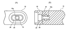
- FIG. 4 is a cross-sectional view taken along the line AA of FIG. 5 is a view showing a state in which the anti-vibration rubber 25 and the bolt are removed, in which (A) is a bottom view and (B) is a cross-sectional view from the same viewpoint as FIG.
- An anti-vibration connection portion 20 is provided on the left side of the loop handle 10 and in the vicinity of the left end portion of the first support portion 21.
- the vibration isolating rubber 25 has a larger crushing margin in the longitudinal left and right direction than the longitudinal front and rear direction, so that the bolt 12 moves in the left and right direction while compressing the vibration isolating rubber 25. It is configured to be possible.
- the allowable amount of relative movement in the left-right direction is larger than the allowable amount of relative movement in the front-rear direction. It is configured.
- the allowable amount of relative movement in the left-right direction between the grip portion 11 and the operation rod 2 is the front-rear direction between the grip portion 11 and the operation rod 2.
- the present invention is not limited to the above-described embodiment, and is within a range not departing from the spirit of the invention described in the claims.
- the design can be changed as appropriate.
- an electric motor may be used as the drive source.
- SYMBOLS 1 Brush cutter (portable working machine), 2 ... Control rod, 3 ... Engine (drive source), 4 ... Gear case, 5 ... Cutting blade, 6 ... Scatter protection cover, 7 ... Rear handle, 8 ... Control lever, 10 ... Loop handle (handle), 11 ... Grasping part, 12 ... Bolt (extension part), 12a ... Male screw part, 12b ... Bolt head (expansion part), 12c ... Step part, 13 ... Nut, 13a ... Female screw part DESCRIPTION OF SYMBOLS 14 ... Transmission shaft, 20 ... Anti-vibration connection part, 21 ... First support part, 22 ... Second support part, 23 ... Anti-vibration rubber accommodating part, 24 ... Long hole part, 25 ... Anti-vibration rubber (elastic body)
Landscapes
- Life Sciences & Earth Sciences (AREA)
- Environmental Sciences (AREA)
- Harvester Elements (AREA)
Abstract
Description
Claims (10)
- 駆動源と、前記駆動源により駆動する工具が前方に配設された操作棹とを備え、前記操作棹に防振接続部を介して把持部が接続された携帯用作業機であって、前記操作棹の長手方向を前後方向としたときに、前記把持部と前記操作棹との左右方向への相対移動の許容量が、前記把持部と前記操作棹の前後方向への相対移動の許容量より大きくなるよう防振接続部により構成されていることを特徴とする、携帯型作業機。
- 前記防振接続部は、前記操作棹側と前記把持部側の一方に、左右方向と交差する方向に延びる延出部を備え、他方に前記延出部が挿入される孔部を備えることを特徴とする、請求項1に記載の携帯型作業機。
- 前記孔部の内側に弾性体が配設されることを特徴とする、請求項2に記載の携帯型作業機。
- 前記孔部は左右方向を長手とする長孔状とされ、前記弾性体は前後方向より左右方向に大きな潰し代を有することを特徴とする、請求項3に記載の携帯型作業機。
- 前記延出部は先端側に拡径部を有し、前記拡径部は前記孔部の最小幅より大きい径を有することを特徴とする、請求項2から請求項4のうち何れか一項に記載の携帯型作業機。
- 前記延出部は基端部側に雄ねじ部を有するボルトであり、前記延出部の先端部はボルト頭部であることを特徴とする請求項5に記載の携帯型作業機。
- 前記把持部は、左右方向の一方が分割して形成されたループ状のハンドルに設けられ、前記防振接続部は前記分割部に設けられたことを特徴とする、請求項1乃至請求項6のうち何れか一項に記載の携帯型作業機。
- 前記把持部は、前記操作棹に対する前記ハンドルの取付位置より後方に位置することを特徴とする、請求項7に記載の携帯型作業機。
- 前記操作棹は、前記駆動源を後方に備え、前記駆動源から前記工具に動力を伝達する伝達軸が、前記操作棹の内部に挿通されて回転可能に支承されることを特徴とする、請求項1乃至請求項8のうち何れか一項に記載の携帯用作業機
- 駆動源と、前記駆動源により駆動する工具が前方に配設された操作棹とを備え、前記操作棹にループ状のハンドルが取り付けられる携帯用作業機であって、前記操作棹の長手方向を前後方向としたときに、前記ハンドルの左右方向の一方が分割され防振接続部を介して接続されるとともに、左右方向の他方が一体に連続して形成されることを特徴とする携帯用作業機。
Priority Applications (3)
| Application Number | Priority Date | Filing Date | Title |
|---|---|---|---|
| CN201690001250.XU CN208956448U (zh) | 2015-10-13 | 2016-09-30 | 便携式作业机 |
| JP2017545146A JP6631636B2 (ja) | 2015-10-13 | 2016-09-30 | 携帯型作業機 |
| DE212016000206.6U DE212016000206U1 (de) | 2015-10-13 | 2016-09-30 | Tragbare Arbeitsmaschine |
Applications Claiming Priority (2)
| Application Number | Priority Date | Filing Date | Title |
|---|---|---|---|
| JP2015-202030 | 2015-10-13 | ||
| JP2015202030 | 2015-10-13 |
Publications (1)
| Publication Number | Publication Date |
|---|---|
| WO2017065023A1 true WO2017065023A1 (ja) | 2017-04-20 |
Family
ID=58517510
Family Applications (1)
| Application Number | Title | Priority Date | Filing Date |
|---|---|---|---|
| PCT/JP2016/079043 Ceased WO2017065023A1 (ja) | 2015-10-13 | 2016-09-30 | 携帯型作業機 |
Country Status (4)
| Country | Link |
|---|---|
| JP (1) | JP6631636B2 (ja) |
| CN (1) | CN208956448U (ja) |
| DE (1) | DE212016000206U1 (ja) |
| WO (1) | WO2017065023A1 (ja) |
Citations (3)
| Publication number | Priority date | Publication date | Assignee | Title |
|---|---|---|---|---|
| JPS51159335U (ja) * | 1975-06-11 | 1976-12-18 | ||
| JPH0631420U (ja) * | 1992-09-30 | 1994-04-26 | 小松ゼノア株式会社 | 防振式環状ハンドル |
| JP2012044976A (ja) * | 2010-08-30 | 2012-03-08 | Starting Industrial Co Ltd | 携帯型刈払い機におけるハンドルの防振機構 |
-
2016
- 2016-09-30 CN CN201690001250.XU patent/CN208956448U/zh not_active Expired - Fee Related
- 2016-09-30 DE DE212016000206.6U patent/DE212016000206U1/de not_active Expired - Lifetime
- 2016-09-30 WO PCT/JP2016/079043 patent/WO2017065023A1/ja not_active Ceased
- 2016-09-30 JP JP2017545146A patent/JP6631636B2/ja not_active Expired - Fee Related
Patent Citations (3)
| Publication number | Priority date | Publication date | Assignee | Title |
|---|---|---|---|---|
| JPS51159335U (ja) * | 1975-06-11 | 1976-12-18 | ||
| JPH0631420U (ja) * | 1992-09-30 | 1994-04-26 | 小松ゼノア株式会社 | 防振式環状ハンドル |
| JP2012044976A (ja) * | 2010-08-30 | 2012-03-08 | Starting Industrial Co Ltd | 携帯型刈払い機におけるハンドルの防振機構 |
Also Published As
| Publication number | Publication date |
|---|---|
| JP6631636B2 (ja) | 2020-01-15 |
| CN208956448U (zh) | 2019-06-11 |
| JPWO2017065023A1 (ja) | 2018-08-02 |
| DE212016000206U1 (de) | 2018-05-15 |
Similar Documents
| Publication | Publication Date | Title |
|---|---|---|
| JP6681226B2 (ja) | チェーンソー | |
| US8549758B2 (en) | Coupling apparatus for coupling blade protector to tool body of gardening tool | |
| CN206445757U (zh) | 动力工具及其传动轴组件 | |
| EP0365703A1 (en) | Hand-held machine | |
| JP6862121B2 (ja) | ロングヘッジトリマ | |
| JP7296833B2 (ja) | 作業機 | |
| US9962779B2 (en) | Counterweight device | |
| JP3825136B2 (ja) | 手持ち式動力作業機 | |
| JP2002253024A (ja) | 刈払機 | |
| EP1530890B1 (en) | Portable device with anti-vibration handle for use in agriculture and gardening | |
| WO2017065023A1 (ja) | 携帯型作業機 | |
| JP7355107B2 (ja) | 電動作業機 | |
| JP2009072149A (ja) | 園芸工具 | |
| JP5265958B2 (ja) | 振動吸収継手及びそれを備えた携帯型刈払機 | |
| JP2013031931A (ja) | 携帯式作業機 | |
| CN101528022B (zh) | 灌木切割机 | |
| JP7273684B2 (ja) | ヘッジトリマ | |
| JP5807410B2 (ja) | チェーンソー | |
| JP2013102734A (ja) | 作業機のパイプ状保持具 | |
| JP4202978B2 (ja) | 刈払機 | |
| JP2008011793A (ja) | 手持ち式動力作業機のハンドル支持構造 | |
| JP2016140276A (ja) | 刈払機 | |
| JP6862120B2 (ja) | ロングヘッジトリマ | |
| JP2008011740A (ja) | 刈払機 | |
| JP2021040580A (ja) | 支持棹および作業機 |
Legal Events
| Date | Code | Title | Description |
|---|---|---|---|
| 121 | Ep: the epo has been informed by wipo that ep was designated in this application |
Ref document number: 16855277 Country of ref document: EP Kind code of ref document: A1 |
|
| WWE | Wipo information: entry into national phase |
Ref document number: 212016000206 Country of ref document: DE |
|
| ENP | Entry into the national phase |
Ref document number: 2017545146 Country of ref document: JP Kind code of ref document: A |
|
| 122 | Ep: pct application non-entry in european phase |
Ref document number: 16855277 Country of ref document: EP Kind code of ref document: A1 |