WO2017064881A1 - 固体レーザ増幅装置 - Google Patents
固体レーザ増幅装置 Download PDFInfo
- Publication number
- WO2017064881A1 WO2017064881A1 PCT/JP2016/067060 JP2016067060W WO2017064881A1 WO 2017064881 A1 WO2017064881 A1 WO 2017064881A1 JP 2016067060 W JP2016067060 W JP 2016067060W WO 2017064881 A1 WO2017064881 A1 WO 2017064881A1
- Authority
- WO
- WIPO (PCT)
- Prior art keywords
- unit
- solid
- laser
- cooling
- medium
- Prior art date
- Legal status (The legal status is an assumption and is not a legal conclusion. Google has not performed a legal analysis and makes no representation as to the accuracy of the status listed.)
- Ceased
Links
Images
Classifications
-
- H—ELECTRICITY
- H01—ELECTRIC ELEMENTS
- H01S—DEVICES USING THE PROCESS OF LIGHT AMPLIFICATION BY STIMULATED EMISSION OF RADIATION [LASER] TO AMPLIFY OR GENERATE LIGHT; DEVICES USING STIMULATED EMISSION OF ELECTROMAGNETIC RADIATION IN WAVE RANGES OTHER THAN OPTICAL
- H01S3/00—Lasers, i.e. devices using stimulated emission of electromagnetic radiation in the infrared, visible or ultraviolet wave range
- H01S3/02—Constructional details
- H01S3/04—Arrangements for thermal management
- H01S3/042—Arrangements for thermal management for solid state lasers
-
- H—ELECTRICITY
- H01—ELECTRIC ELEMENTS
- H01S—DEVICES USING THE PROCESS OF LIGHT AMPLIFICATION BY STIMULATED EMISSION OF RADIATION [LASER] TO AMPLIFY OR GENERATE LIGHT; DEVICES USING STIMULATED EMISSION OF ELECTROMAGNETIC RADIATION IN WAVE RANGES OTHER THAN OPTICAL
- H01S3/00—Lasers, i.e. devices using stimulated emission of electromagnetic radiation in the infrared, visible or ultraviolet wave range
- H01S3/02—Constructional details
- H01S3/04—Arrangements for thermal management
- H01S3/0407—Liquid cooling, e.g. by water
-
- H—ELECTRICITY
- H01—ELECTRIC ELEMENTS
- H01S—DEVICES USING THE PROCESS OF LIGHT AMPLIFICATION BY STIMULATED EMISSION OF RADIATION [LASER] TO AMPLIFY OR GENERATE LIGHT; DEVICES USING STIMULATED EMISSION OF ELECTROMAGNETIC RADIATION IN WAVE RANGES OTHER THAN OPTICAL
- H01S3/00—Lasers, i.e. devices using stimulated emission of electromagnetic radiation in the infrared, visible or ultraviolet wave range
- H01S3/05—Construction or shape of optical resonators; Accommodation of active medium therein; Shape of active medium
- H01S3/06—Construction or shape of active medium
- H01S3/0602—Crystal lasers or glass lasers
- H01S3/0606—Crystal lasers or glass lasers with polygonal cross-section, e.g. slab, prism
-
- H—ELECTRICITY
- H01—ELECTRIC ELEMENTS
- H01S—DEVICES USING THE PROCESS OF LIGHT AMPLIFICATION BY STIMULATED EMISSION OF RADIATION [LASER] TO AMPLIFY OR GENERATE LIGHT; DEVICES USING STIMULATED EMISSION OF ELECTROMAGNETIC RADIATION IN WAVE RANGES OTHER THAN OPTICAL
- H01S3/00—Lasers, i.e. devices using stimulated emission of electromagnetic radiation in the infrared, visible or ultraviolet wave range
- H01S3/05—Construction or shape of optical resonators; Accommodation of active medium therein; Shape of active medium
- H01S3/06—Construction or shape of active medium
- H01S3/0602—Crystal lasers or glass lasers
- H01S3/0612—Non-homogeneous structure
-
- H—ELECTRICITY
- H01—ELECTRIC ELEMENTS
- H01S—DEVICES USING THE PROCESS OF LIGHT AMPLIFICATION BY STIMULATED EMISSION OF RADIATION [LASER] TO AMPLIFY OR GENERATE LIGHT; DEVICES USING STIMULATED EMISSION OF ELECTROMAGNETIC RADIATION IN WAVE RANGES OTHER THAN OPTICAL
- H01S3/00—Lasers, i.e. devices using stimulated emission of electromagnetic radiation in the infrared, visible or ultraviolet wave range
- H01S3/005—Optical devices external to the laser cavity, specially adapted for lasers, e.g. for homogenisation of the beam or for manipulating laser pulses, e.g. pulse shaping
-
- H—ELECTRICITY
- H01—ELECTRIC ELEMENTS
- H01S—DEVICES USING THE PROCESS OF LIGHT AMPLIFICATION BY STIMULATED EMISSION OF RADIATION [LASER] TO AMPLIFY OR GENERATE LIGHT; DEVICES USING STIMULATED EMISSION OF ELECTROMAGNETIC RADIATION IN WAVE RANGES OTHER THAN OPTICAL
- H01S3/00—Lasers, i.e. devices using stimulated emission of electromagnetic radiation in the infrared, visible or ultraviolet wave range
- H01S3/02—Constructional details
- H01S3/025—Constructional details of solid state lasers, e.g. housings or mountings
-
- H—ELECTRICITY
- H01—ELECTRIC ELEMENTS
- H01S—DEVICES USING THE PROCESS OF LIGHT AMPLIFICATION BY STIMULATED EMISSION OF RADIATION [LASER] TO AMPLIFY OR GENERATE LIGHT; DEVICES USING STIMULATED EMISSION OF ELECTROMAGNETIC RADIATION IN WAVE RANGES OTHER THAN OPTICAL
- H01S3/00—Lasers, i.e. devices using stimulated emission of electromagnetic radiation in the infrared, visible or ultraviolet wave range
- H01S3/02—Constructional details
- H01S3/04—Arrangements for thermal management
- H01S3/0405—Conductive cooling, e.g. by heat sinks or thermo-electric elements
-
- H—ELECTRICITY
- H01—ELECTRIC ELEMENTS
- H01S—DEVICES USING THE PROCESS OF LIGHT AMPLIFICATION BY STIMULATED EMISSION OF RADIATION [LASER] TO AMPLIFY OR GENERATE LIGHT; DEVICES USING STIMULATED EMISSION OF ELECTROMAGNETIC RADIATION IN WAVE RANGES OTHER THAN OPTICAL
- H01S3/00—Lasers, i.e. devices using stimulated emission of electromagnetic radiation in the infrared, visible or ultraviolet wave range
- H01S3/05—Construction or shape of optical resonators; Accommodation of active medium therein; Shape of active medium
- H01S3/06—Construction or shape of active medium
- H01S3/0602—Crystal lasers or glass lasers
- H01S3/0604—Crystal lasers or glass lasers in the form of a plate or disc
-
- H—ELECTRICITY
- H01—ELECTRIC ELEMENTS
- H01S—DEVICES USING THE PROCESS OF LIGHT AMPLIFICATION BY STIMULATED EMISSION OF RADIATION [LASER] TO AMPLIFY OR GENERATE LIGHT; DEVICES USING STIMULATED EMISSION OF ELECTROMAGNETIC RADIATION IN WAVE RANGES OTHER THAN OPTICAL
- H01S3/00—Lasers, i.e. devices using stimulated emission of electromagnetic radiation in the infrared, visible or ultraviolet wave range
- H01S3/05—Construction or shape of optical resonators; Accommodation of active medium therein; Shape of active medium
- H01S3/06—Construction or shape of active medium
- H01S3/0619—Coatings, e.g. AR, HR, passivation layer
- H01S3/0621—Coatings on the end-faces, e.g. input/output surfaces of the laser light
-
- H—ELECTRICITY
- H01—ELECTRIC ELEMENTS
- H01S—DEVICES USING THE PROCESS OF LIGHT AMPLIFICATION BY STIMULATED EMISSION OF RADIATION [LASER] TO AMPLIFY OR GENERATE LIGHT; DEVICES USING STIMULATED EMISSION OF ELECTROMAGNETIC RADIATION IN WAVE RANGES OTHER THAN OPTICAL
- H01S3/00—Lasers, i.e. devices using stimulated emission of electromagnetic radiation in the infrared, visible or ultraviolet wave range
- H01S3/14—Lasers, i.e. devices using stimulated emission of electromagnetic radiation in the infrared, visible or ultraviolet wave range characterised by the material used as the active medium
- H01S3/16—Solid materials
- H01S3/1601—Solid materials characterised by an active (lasing) ion
- H01S3/1603—Solid materials characterised by an active (lasing) ion rare earth
- H01S3/1611—Solid materials characterised by an active (lasing) ion rare earth neodymium
-
- H—ELECTRICITY
- H01—ELECTRIC ELEMENTS
- H01S—DEVICES USING THE PROCESS OF LIGHT AMPLIFICATION BY STIMULATED EMISSION OF RADIATION [LASER] TO AMPLIFY OR GENERATE LIGHT; DEVICES USING STIMULATED EMISSION OF ELECTROMAGNETIC RADIATION IN WAVE RANGES OTHER THAN OPTICAL
- H01S3/00—Lasers, i.e. devices using stimulated emission of electromagnetic radiation in the infrared, visible or ultraviolet wave range
- H01S3/14—Lasers, i.e. devices using stimulated emission of electromagnetic radiation in the infrared, visible or ultraviolet wave range characterised by the material used as the active medium
- H01S3/16—Solid materials
- H01S3/163—Solid materials characterised by a crystal matrix
- H01S3/164—Solid materials characterised by a crystal matrix garnet
- H01S3/1643—YAG
-
- H—ELECTRICITY
- H01—ELECTRIC ELEMENTS
- H01S—DEVICES USING THE PROCESS OF LIGHT AMPLIFICATION BY STIMULATED EMISSION OF RADIATION [LASER] TO AMPLIFY OR GENERATE LIGHT; DEVICES USING STIMULATED EMISSION OF ELECTROMAGNETIC RADIATION IN WAVE RANGES OTHER THAN OPTICAL
- H01S3/00—Lasers, i.e. devices using stimulated emission of electromagnetic radiation in the infrared, visible or ultraviolet wave range
- H01S3/14—Lasers, i.e. devices using stimulated emission of electromagnetic radiation in the infrared, visible or ultraviolet wave range characterised by the material used as the active medium
- H01S3/16—Solid materials
- H01S3/1685—Ceramics
-
- H—ELECTRICITY
- H01—ELECTRIC ELEMENTS
- H01S—DEVICES USING THE PROCESS OF LIGHT AMPLIFICATION BY STIMULATED EMISSION OF RADIATION [LASER] TO AMPLIFY OR GENERATE LIGHT; DEVICES USING STIMULATED EMISSION OF ELECTROMAGNETIC RADIATION IN WAVE RANGES OTHER THAN OPTICAL
- H01S3/00—Lasers, i.e. devices using stimulated emission of electromagnetic radiation in the infrared, visible or ultraviolet wave range
- H01S3/23—Arrangements of two or more lasers not provided for in groups H01S3/02 - H01S3/22, e.g. tandem arrangements of separate active media
- H01S3/2308—Amplifier arrangements, e.g. MOPA
- H01S3/2316—Cascaded amplifiers
Definitions
- the present invention relates to a solid-state laser amplifier.
- a solid-state laser is a laser that uses a solid as a laser medium.
- a solid-state laser amplifier is an apparatus that improves (amplifies) the output of laser light by transmitting the laser light into a laser medium. For example, in the case of a slab-type solid-state laser amplifier, amplification is performed by advancing the laser medium in a zigzag manner while reflecting the laser light incident inside the laser medium on both opposing surfaces of the laser medium.
- the laser medium needs to be cooled because it is heated by the laser beam passing through the inside.
- direct cooling has been used for cooling the laser medium.
- direct cooling for example, the inside of a cooling chamber provided so as to cover the surface of the laser medium is pressurized, and cooling is performed by injecting liquid nitrogen toward the laser medium surface in the cooling chamber.
- the cooling chamber into which liquid nitrogen is injected needs to be sealed for cooling, and is sealed from the outside by providing a sealing material between the laser medium and the cooling chamber, for example.
- sealing with a sealing material may be difficult due to thermal elongation due to temperature change of the laser medium. If the sealing is not performed properly, the laser medium may not be properly cooled.
- an object of the present invention is to provide a solid-state laser amplifier that appropriately cools a laser medium.
- a solid-state laser amplification device is a solid medium in which laser light is incident on the inside from an incident portion and the laser light is emitted to the outside from an emission portion. And a laser medium part that is provided on the surface of the medium and receives a laser beam in the medium and reflects the laser beam while amplifying it toward the emitting part, and a micro that cools the amplification layer A channel-type cooling unit; and a heat conduction unit that is provided in contact between the amplification layer and the cooling unit and transfers heat of the amplification layer to the cooling unit.
- this solid-state laser amplifying apparatus since it is indirect cooling, it is not necessary to perform sealing to cool the laser medium part, and the laser medium part can be appropriately cooled.
- the amplification layer, the heat conducting unit, and the cooling unit are provided on each of the opposing surfaces of the medium.
- the amplifying layer which is a place where the laser beam is received and is likely to become high temperature, is reliably cooled, so that the amplifying layer can be cooled more appropriately.
- the solid-state laser amplification device it is preferable that a plurality of the cooling unit and the heat conducting unit are provided at a predetermined interval along the traveling direction of the laser beam. According to this solid-state laser amplifying device, it is possible to suppress the temperature distribution in the laser medium portion from being biased, and to suppress the performance degradation of the laser beam.
- the heat conducting unit is a graphite sheet, one surface is in contact with the amplifying layer, and the other surface is in contact with the cooling unit. According to this solid-state laser amplifying device, since the heat conducting part is a graphite sheet having a high thermal conductivity, the heat of the amplifying layer can be more efficiently transmitted to the cooling part.
- the heat conduction unit has a heat conductivity along a direction parallel to the one surface higher than a heat conductivity along a direction intersecting the one surface.
- the heat of the amplification layer can be diffused toward the surface of the heat conducting unit, and the heat can be cooled over the entire surface of the cooling unit. Therefore, this heat conduction part can cool an amplification layer more appropriately.
- the heat conduction unit has a heat conductivity along a direction parallel to the one surface that is lower than a heat conductivity along a direction intersecting the one surface. According to this solid-state laser amplifying device, heat can be quickly transmitted in the direction from the amplifying layer to the cooling unit, so that the amplifying layer can be cooled more rapidly.
- a surface of the cooling unit that contacts the heat conducting unit is a graphite sheet. According to this solid-state laser amplification device, the thermal conductivity of the cooling unit itself can be increased, so that the amplification layer can be cooled more appropriately.
- the laser medium can be appropriately cooled.
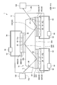
- FIG. 1 is a schematic diagram illustrating a configuration of a solid-state laser device according to the present embodiment.
- FIG. 2 is a schematic diagram of a cooling unit in the present embodiment.
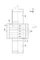
- FIG. 3 is a schematic view of the solid-state laser amplification device according to this embodiment as viewed from above.
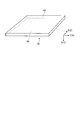
- FIG. 4 is a schematic diagram illustrating the shape of the heat conducting unit.
- FIG. 1 is a schematic diagram illustrating a configuration of a solid-state laser device according to the present embodiment.
- the solid-state laser device 1 according to the present embodiment is a device that irradiates a solid-state laser using a solid as a medium, and is a slab type solid-state laser irradiation device.
- the solid-state laser device 1 includes a solid-state laser amplification device 10, a storage chamber 12, a light emitting unit 100, and an irradiation unit 102.
- the light emitting unit 100 is an excitation light source of the laser light L, and is a laser diode, for example.
- the irradiation unit 102 is, for example, a laser irradiation head.
- the solid-state laser device 1 transmits and amplifies the laser light L excited by the light emitting unit 100 through the solid-state laser amplifying device 10 provided in the storage chamber 12, and irradiates the amplified laser light L from the irradiation unit 102. To do.
- the solid-state laser device 1 irradiates the laser beam L from the irradiation unit 102 and performs machining or the like. Note that the laser beam L emitted from the solid-state laser device 1 has a high output of, for example, 100 W / cm 2 or more.
- the storage chamber 12 is a chamber in which the solid-state laser amplification device 10 is stored.
- the storage chamber 12 is a chamber sealed from the outside, and in use, the internal gas is exhausted by a pump or the like and is in a vacuum state.
- the storage chamber 12 is provided with an entrance window 12a and an exit window 12b.
- the laser beam L from the light emitting unit 100 is transmitted through the entrance window 12a to the inside, and the internal laser beam L is irradiated from the exit window 12b to the irradiation unit 102. To emit light.
- the solid-state laser amplifying apparatus 10 is a so-called slab type solid-state laser amplifying apparatus.
- the solid-state laser amplifying apparatus 10 includes a laser medium unit 20, cooling units 30A, 30B, and 30C, and heat conducting units 40A, 40B, and 40C.
- the laser medium unit 20 is a slab type laser medium for amplifying the laser light L.
- the laser medium unit 20 is Nd: YAG ceramic in the present embodiment.
- Nd: YAG ceramics are obtained by doping a part of yttrium with neodymium in the process of producing YAG (Yttrium Aluminum Garnet) crystals.
- the laser medium unit 20 includes a medium 22 and amplification layers 24A, 24B, and 24C.
- the medium 22 is a translucent crystal (solid) such as YAG, for example.
- the amplification layers 24 ⁇ / b> A, 24 ⁇ / b> B, and 24 ⁇ / b> C are layers provided on the surface of the medium 22, and are generated by doping a plate made of the same material as the medium 22 with ions such as yttrium.
- the amplification layers 24A, 24B, and 24C are gain media that amplify the laser light L.
- the medium 22 is a hexahedron (in this embodiment, a frustum).
- the length of the medium 22 along the direction X is longer than the length along the direction Y.
- the direction Y is a direction that intersects the direction X, and is a direction that is orthogonal to the direction X in the present embodiment.
- a direction Z described later is a direction intersecting with the direction X and the direction Y, and is a direction orthogonal to the direction X and the direction Y in the present embodiment.
- one surface along the direction Y is an upper bottom surface 22a on the side having a smaller area, and the other surface is a lower and lower surface 22b on the side having a larger area.
- the shape of the medium 22 is not limited to this.
- the amplification layers 24A and 24C are attached to the lower surface 22b with a predetermined interval along the direction X.
- the amplification layer 24B is attached to the upper bottom surface 22a.
- the amplification layer 24B is located along the direction X between the amplification layer 24A and the amplification layer 24C.
- a plurality of amplification layers may be attached at predetermined intervals similarly to the lower bottom surface 22b.
- the amplification layers 24A, 24B, and 24C are not distinguished, they are referred to as amplification layers 24. It can be said that the amplification layer 24 is provided on each of the surfaces (upper bottom surface 22a and lower bottom surface 24b) facing each other in the direction Y of the medium 22. Further, it can be said that a plurality of amplification layers 24 are provided on the surface of the medium 22 at a predetermined interval along the direction X. However, the amplification layer 24 may not be provided at a predetermined interval along the direction X, and may be provided over the entire upper bottom surface 22a and the lower bottom surface 24b.
- Laser light L is incident on the inside of the medium 22 from the incident portion 26 on the side surface of the medium 22.
- the laser beam L incident on the inside of the medium 22 enters the amplification layer 24.
- the laser beam L incident on the amplification layer 24 is amplified and reflected by the surface 25 which is the surface of the amplification layer 24 opposite to the medium 22.
- the laser beam L reflected by the surface 25 is incident again into the medium 22 from the amplification layer 24 and is emitted from the emitting portion 27 on the side surface opposite to the incident portion 26 along the direction X.
- the surface 25 may be provided with a reflective layer that totally reflects the laser light L.
- the laser beam L incident in the storage chamber 12 enters the amplification layer 24A from the incident portion 26 through the medium 22.
- the laser beam L incident on the amplification layer 24A is amplified and reflected, and enters the amplification layer 24B via the medium 22.
- the laser light L incident on the amplification layer 24B is amplified and reflected, and enters the amplification layer 24C via the medium 22.
- the laser beam L that has entered the amplification layer 24C is amplified and reflected, enters the medium 22, and is emitted from the emission unit 27 toward the outside (the storage chamber 12).
- the laser light L in the present embodiment proceeds zigzag in the direction X in the laser medium unit 20. Therefore, the direction X can also be referred to as the traveling direction of the laser light L.
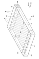
- FIG. 2 is a schematic diagram of a cooling unit in the present embodiment.
- the cooling unit 30 is a microchannel heat exchanger. As shown in FIG. 2, the cooling unit 30 includes a microchannel unit 31, an inlet header unit 32, and an outlet header unit 34.
- the microchannel portion 31 is a plate-like member having a plurality of flow paths 36 opened therein.
- the flow path 36 extends along a direction A parallel to the surface 31 a of the microchannel portion 31.
- the flow path 36 opens to one side surface 31b and the other side surface 31c of the microchannel portion 31 along the direction A, and is electrically connected from the one side surface 31b to the other side surface 31c.
- a plurality (five in this embodiment) of the flow paths 36 are arranged along a direction B that is a direction parallel to the surface 31 a of the microchannel portion 31 and intersects the direction A.
- the microchannel portion 31 is a metal member having a relatively high thermal conductivity such as aluminum or SUS (stainless steel), but the material is not limited thereto.
- the inlet header portion 32 is a cylindrical member having a hollow inside.
- the inlet header portion 32 is attached to one side surface 31 b of the microchannel portion 31.
- the inlet header 32 has an opening (not shown) for connecting the internal space with each of the plurality of flow paths 36, and an introduction opening 32a for introducing the cooling solvent W into the internal space. .
- the outlet header 34 is a cylindrical member having a hollow inside.
- the outlet header portion 34 is attached to the other side surface 31 b of the microchannel portion 31.
- the outlet header 34 has an opening (not shown) for connecting the internal space with each of the plurality of flow paths 36, and a lead-out opening 34a for introducing the cooling solvent W from the internal space to the outside. ing.
- the cooling part 30 introduces the cooling solvent W into the inlet header part 32 from the introduction opening part 32 a, distributes the cooling solvent W to each flow path 36, and circulates it in each flow path 36.
- the microchannel unit 31 is in contact with the object to be cooled, and cools the object to be cooled by the cooling solvent W flowing through each flow path 36.
- the cooling solvent W flowing in each flow path 36 flows toward the outlet header portion 34.
- the cooling solvent W that has flowed into the outlet header portion 34 is led out to the outside from the lead-out opening portion 34a, cooled outside, and introduced into the inlet header portion 32 again.
- the cooling solvent W in this embodiment is a liquid in the state introduce
- FIG. 3 is a schematic view of the solid-state laser amplification device according to this embodiment as viewed from above.
- the cooling unit 30 has a surface 31 a attached to the surface 42 of the amplification layer 24 via the heat conducting units 40 ⁇ / b> A, 40 ⁇ / b> B, and 40 ⁇ / b> C, and cools the amplification layer 24.
- the cooling unit 30A is attached to the amplification layer 24A.
- the cooling unit 30B is attached to the amplification layer 24B.
- the cooling unit 30C is attached to the amplification layer 24C.
- the cooling unit 30 is provided on each of the surfaces (the surface on the upper bottom surface 22a side and the surface on the lower bottom surface 24b side) facing each other in the direction Y of the laser medium unit 20.
- a plurality of cooling units 30 are provided on the surface of the laser medium unit 20 at a predetermined interval along the direction X. That is, the cooling unit 30 is provided only in the amplification layer 24 in the laser medium unit 20 that receives (amplifies and reflects) the laser light L and becomes high temperature.
- the cooling unit 30 is attached to each amplification layer 24 so that the direction A in which the flow paths 36 extend is along the direction Z and the direction B in which the plurality of flow paths 36 are aligned is along the direction X.
- the attachment direction of the cooling unit 30 is not limited to this as long as the surface 31a is attached to the surface 42 of the amplification layer 24.
- the direction A in which the flow path 36 extends is along the direction X. Good.
- the cooling unit 30 is connected to a cooling solvent cooling unit 50.
- the cooling solvent cooling unit 50 is provided outside the storage chamber 12, and introduces the cooling solvent W into the introduction opening 32 a of the inlet header unit 32 through the introduction pipe 52.
- the cooling solvent cooling unit 50 derives the cooling solvent W from the outlet opening 34 a of the outlet header 34 via the outlet pipe 54.
- the cooling solvent cooling unit 50 cools the cooling solvent W from the outlet header 34 and supplies it to the inlet header 32 again.
- the configuration of the cooling solvent cooling unit 50 is arbitrary as long as it cools the cooling solvent W.
- the cooling solvent cooling unit 50 may naturally cool by providing fins between a plurality of tubes through which the cooling solvent W is conducted. It may be forcibly cooled.
- FIG. 4 is a schematic diagram illustrating the shape of the heat conducting unit.
- the heat conducting unit 40 is a plate-like member having high thermal conductivity, and is provided in contact between the amplifying layer 24 and the cooling unit 30, and the heat of the amplifying layer 24. The heat is transferred to the cooling unit 30.
- the heat conducting unit 40 is provided in close contact between the amplification layer 24 and the cooling unit 30.
- one surface 42 is in contact with the surface 25 of the amplification layer 24A, and the other surface 44 is in contact with the surface 31a of the cooling unit 30A.
- one surface 42 is in contact with the surface 25 of the amplification layer 24B, and the other surface 44 is in contact with the surface 31a of the cooling unit 30B.
- one surface 42 is in contact with the surface 25 of the amplification layer 24C, and the other surface 44 is in contact with the surface 31a of the cooling unit 30C.
- the heat conducting unit 40 is provided on each of the surfaces (the surface on the upper bottom surface 22a side and the surface on the lower bottom surface 24b side) facing each other along the direction Y of the laser medium unit 20.
- a plurality of the heat conducting units 40 are provided on the surface of the laser medium unit 20 at a predetermined interval along the direction X.
- the heat conducting unit 40 is provided only in the amplification layer 24 that receives the laser beam L and becomes high temperature in the laser medium unit 20.
- the heat conducting unit 40 is made of a material having a higher thermal conductivity than the laser medium unit 20 and the cooling unit 30, and is a graphite sheet in the present embodiment.
- the graphite sheet is a sheet containing graphite (graphite), and is formed, for example, by stretching a mixture of graphite powder and a binder resin, or expanded graphite into a sheet shape.
- the heat conducting unit 40 in the present embodiment is a direction in which the graphite layers extending along the directions C and D that are parallel to the surfaces (one surface 42 and the other surface 44) are perpendicular to the surface. Laminated along E. This graphite layer is oriented along a direction parallel to the surface (for example, directions C and D), and has anisotropy in thermal conductivity.
- the thermal conductivity of the heat conducting unit 40 along the direction C and the direction D is higher than the thermal conductivity along the direction E. That is, the heat conducting unit 40 is more likely to transmit heat in the direction along the direction C and the direction D than in the direction E.
- the thickness of the heat conductive part 40 in this embodiment is 0.1 mm or more and 1 mm or less, it is not restricted to this.
- the heat conducting unit 40 is attached such that one surface 42 contacts the surface 25 of the amplification layer 24 and the other surface 44 contacts the surface 31 a of the cooling unit 30. Further, the heat conducting unit 40 is mounted such that the direction C is a direction parallel to the direction X, the direction D is a direction parallel to the direction Z, and the direction E is a direction parallel to the direction Y. However, if the direction E is a direction parallel to the direction Y, the attachment direction is not restricted to this.
- the solid-state laser amplification device 10 described above includes a laser medium unit 20 having a medium 22 and an amplification layer 24, a cooling unit 30, and a heat conduction unit 40.
- the medium 22 is a solid laser medium in which the laser beam L is incident from the incident unit 26 and the laser beam L is emitted to the outside from the emitting unit 27.
- the amplification layer 24 is provided on the surface of the medium 22, receives the laser light L in the medium 22, and reflects the laser light L while amplifying it toward the emission unit 27.
- the cooling unit 30 is a microchannel heat exchanger that cools the amplification layer 24.
- the heat conducting unit 40 is provided in contact with the amplification layer 24 and the cooling unit 30, and transfers the heat of the amplification layer 24 to the cooling unit 30.
- the solid-state laser amplifying apparatus 10 since the laser beam L is incident on the amplification layer 24, the amplification layer 24 is heated by the laser beam L.
- a microchannel type cooling unit 30 is attached to the amplification layer 24 via a heat conducting unit 40. Therefore, the heat of the amplification layer 24 is transmitted to the cooling unit 30 via the heat conducting unit 40 and indirectly cooled by the cooling solvent W flowing in the cooling unit 30. Since the solid-state laser amplifying apparatus 10 is indirectly cooled, for example, unlike direct cooling in which liquid nitrogen is injected into the laser medium unit 20 (amplifying layer 24), it is necessary to perform sealing to cool the laser medium unit 20. Absent. Therefore, according to this solid-state laser amplifier 10, the laser medium unit 20 can be appropriately cooled.
- the solid-state laser amplifying apparatus 10 conducts heat to the cooling unit 30 via the heat conducting unit 40. Therefore, the solid-state laser amplification device 10 can efficiently transfer the heat of the amplification layer 24 to the cooling unit 30, and can cool the amplification layer 24 more appropriately.
- this solid-state laser amplification device 10 the amplification layer 24, the cooling unit 30, and the heat conduction unit 40 are provided on each of the surfaces facing in the direction Y of the medium 22. Therefore, this solid-state laser amplifying apparatus 10 is a slab type solid-state laser in which the laser light L travels in a zigzag manner. The cooling part 30 and the heat conducting part 40 can be reliably provided in the layer 24). Therefore, the solid-state laser amplifying apparatus 10 can more efficiently remove the heat of the amplification layer 24 and cool the amplification layer 24 more appropriately.
- the solid-state laser amplifying apparatus 10 is provided with a plurality of cooling units 30 and heat conducting units 40 at predetermined intervals along the traveling direction (direction X) of the laser light L.
- the cooling unit 30 and the heat conducting unit 40 are provided only at a place where the laser beam L is received and the temperature tends to be high (in this embodiment, the amplifying layer 24 provided on the bottom surface 23 of the medium 22). be able to. Therefore, the solid-state laser amplifying apparatus 10 can cool the high-temperature part more than the low-temperature part, and can suppress the temperature distribution in the laser medium part 20 from being biased. Thereby, this solid-state laser amplifying apparatus 10 can suppress the performance degradation of the laser light L.
- the heat conducting unit 40 is a graphite sheet, one surface 42 is in contact with the amplification layer 24, and the other surface 44 is in contact with the cooling unit 30. Since the heat conducting unit 40 is a graphite sheet having a high thermal conductivity, the heat of the amplification layer 24 can be transmitted to the cooling unit 30 more efficiently, and the amplification layer 24 can be cooled more appropriately.
- the heat conducting unit 40 is not limited to being a graphite sheet, and any material can be used as long as it can efficiently transfer the heat of the amplification layer 24 to the cooling unit 30.
- the heat conduction part 40 has a heat conductivity along a direction (direction C, D) parallel to one surface 42 more than a heat conductivity along a direction (direction E) intersecting the one surface 42. high. Therefore, the solid-state laser amplification device 10 can diffuse the heat of the amplification layer 24 toward the surface of the heat conducting unit 40 and cool the heat on the entire surface 31 a of the cooling unit 30. Therefore, the heat conducting unit 40 can cool the amplification layer 24 more appropriately.
- the solid-state laser amplification device 10 diffuses the heat of the amplification layer 24 toward the surface of the heat conducting unit 40, the heat of the amplification layer 24 is made uniform along the surface, and the temperature distribution in the laser medium unit 20 is It is also possible to suppress the bias.
- the heat conductivity along the direction (direction C, D) parallel to the one surface 42 is higher than the heat conductivity along the direction (direction E) intersecting the one surface 42. It may be lower.
- the graphite layer extending along the direction E is laminated along the direction C or the direction D. In this case, since heat can be quickly transferred in the direction E, that is, in the direction from the amplification layer 24 toward the cooling unit 30, the amplification layer 24 can be cooled more rapidly.
- the microchannel portion 31 is a metal member, but at least the surface 31 a that is a surface in contact with the heat conducting portion 40 may be formed of a graphite sheet in the same manner as the heat conducting portion 40. Good. In this case, since the thermal conductivity of the microchannel part 31 itself becomes higher, the amplification layer 24 can be cooled more appropriately.
- the portion between the surface 31a and the plurality of flow paths 36 is preferably configured by laminating graphite sheets.
- the graphite sheet may be laminated
- Solid state laser apparatus 10 Solid state laser amplifying apparatus 12 Storage chamber 12a Incident window 12b Outgoing window 20 Laser medium part 22 Medium 24, 24A, 24B, 24C Amplifying layer 25 Surface 26 Incident part 27 Emitting part 30, 30A, 30B, 30C Cooling part 31 Microchannel portion 31a Surface 31b, 31c Side surface 32 Inlet header portion 32a Inlet opening portion 34 Outlet header portion 34a Outlet opening portion 36 Flow path 40, 40A, 40B, 40C Heat conducting portion 42, 44 Surface 50 Cooling solvent cooling portion 52 Introduction Tube 54 Lead tube 100 Light emitting portion 102 Irradiation portion A, B, C, D, E, X, Y, Z direction L Laser light W Cooling solvent
Landscapes
- Physics & Mathematics (AREA)
- Electromagnetism (AREA)
- Engineering & Computer Science (AREA)
- Plasma & Fusion (AREA)
- Optics & Photonics (AREA)
- Chemical & Material Sciences (AREA)
- Crystallography & Structural Chemistry (AREA)
- Lasers (AREA)
Priority Applications (2)
| Application Number | Priority Date | Filing Date | Title |
|---|---|---|---|
| US15/574,190 US10290991B2 (en) | 2015-10-16 | 2016-06-08 | Solid laser amplification device |
| EP16855135.6A EP3288127B1 (en) | 2015-10-16 | 2016-06-08 | Solid laser amplification device |
Applications Claiming Priority (2)
| Application Number | Priority Date | Filing Date | Title |
|---|---|---|---|
| JP2015-204802 | 2015-10-16 | ||
| JP2015204802A JP6632315B2 (ja) | 2015-10-16 | 2015-10-16 | 固体レーザ増幅装置 |
Publications (1)
| Publication Number | Publication Date |
|---|---|
| WO2017064881A1 true WO2017064881A1 (ja) | 2017-04-20 |
Family
ID=58518114
Family Applications (1)
| Application Number | Title | Priority Date | Filing Date |
|---|---|---|---|
| PCT/JP2016/067060 Ceased WO2017064881A1 (ja) | 2015-10-16 | 2016-06-08 | 固体レーザ増幅装置 |
Country Status (4)
| Country | Link |
|---|---|
| US (1) | US10290991B2 (https=) |
| EP (1) | EP3288127B1 (https=) |
| JP (1) | JP6632315B2 (https=) |
| WO (1) | WO2017064881A1 (https=) |
Cited By (1)
| Publication number | Priority date | Publication date | Assignee | Title |
|---|---|---|---|---|
| EP3576232A3 (en) * | 2018-05-30 | 2020-02-05 | Hamamatsu Photonics K.K. | Laser device |
Citations (4)
| Publication number | Priority date | Publication date | Assignee | Title |
|---|---|---|---|---|
| JP2001015844A (ja) * | 1999-06-30 | 2001-01-19 | Saifasha:Yugen | 固体レーザ装置 |
| JP2008532264A (ja) * | 2005-02-10 | 2008-08-14 | チエン−ミン・ソン | 炭素質複合材ヒート・スプレッダおよびこれに関連した方法 |
| JP2014022568A (ja) * | 2012-07-18 | 2014-02-03 | Osaka Univ | レーザ媒質ユニット、レーザ増幅器及びレーザ発振器並びに冷却方法 |
| JP2014504011A (ja) * | 2010-12-17 | 2014-02-13 | ファイバークリスト | レーザゲインモジュールおよびそのようなモジュールを製造する方法 |
Family Cites Families (10)
| Publication number | Priority date | Publication date | Assignee | Title |
|---|---|---|---|---|
| US3633126A (en) | 1969-04-17 | 1972-01-04 | Gen Electric | Multiple internal reflection face-pumped laser |
| JPS5135207B2 (https=) | 1972-10-28 | 1976-10-01 | ||
| JP3338974B2 (ja) | 1995-01-11 | 2002-10-28 | ミヤチテクノス株式会社 | レーザ装置 |
| JPH09181376A (ja) | 1995-12-26 | 1997-07-11 | Mitsubishi Heavy Ind Ltd | 固体レーザ励起用半導体レーザ及びその製造方法 |
| US6002695A (en) * | 1996-05-31 | 1999-12-14 | Dpss Lasers, Inc. | High efficiency high repetition rate, intra-cavity tripled diode pumped solid state laser |
| US6339605B1 (en) * | 2000-02-16 | 2002-01-15 | The Boeing Company | Active mirror amplifier system and method for a high-average power laser system |
| US6625193B2 (en) | 2001-01-22 | 2003-09-23 | The Boeing Company | Side-pumped active mirror solid-state laser for high-average power |
| US20060083276A1 (en) * | 2004-09-28 | 2006-04-20 | Snake Creek Lasers, Llc. | Cryogenically cooled solid state lasers |
| US7430230B2 (en) | 2005-04-07 | 2008-09-30 | The Boeing Company | Tube solid-state laser |
| JP2010034413A (ja) * | 2008-07-30 | 2010-02-12 | Hamamatsu Photonics Kk | 固体レーザ装置 |
-
2015
- 2015-10-16 JP JP2015204802A patent/JP6632315B2/ja active Active
-
2016
- 2016-06-08 US US15/574,190 patent/US10290991B2/en active Active
- 2016-06-08 WO PCT/JP2016/067060 patent/WO2017064881A1/ja not_active Ceased
- 2016-06-08 EP EP16855135.6A patent/EP3288127B1/en active Active
Patent Citations (4)
| Publication number | Priority date | Publication date | Assignee | Title |
|---|---|---|---|---|
| JP2001015844A (ja) * | 1999-06-30 | 2001-01-19 | Saifasha:Yugen | 固体レーザ装置 |
| JP2008532264A (ja) * | 2005-02-10 | 2008-08-14 | チエン−ミン・ソン | 炭素質複合材ヒート・スプレッダおよびこれに関連した方法 |
| JP2014504011A (ja) * | 2010-12-17 | 2014-02-13 | ファイバークリスト | レーザゲインモジュールおよびそのようなモジュールを製造する方法 |
| JP2014022568A (ja) * | 2012-07-18 | 2014-02-03 | Osaka Univ | レーザ媒質ユニット、レーザ増幅器及びレーザ発振器並びに冷却方法 |
Cited By (2)
| Publication number | Priority date | Publication date | Assignee | Title |
|---|---|---|---|---|
| EP3576232A3 (en) * | 2018-05-30 | 2020-02-05 | Hamamatsu Photonics K.K. | Laser device |
| US11114810B2 (en) | 2018-05-30 | 2021-09-07 | Hamamatsu Photonics K.K. | Laser device |
Also Published As
| Publication number | Publication date |
|---|---|
| JP6632315B2 (ja) | 2020-01-22 |
| EP3288127A4 (en) | 2018-09-26 |
| EP3288127A1 (en) | 2018-02-28 |
| EP3288127B1 (en) | 2021-03-10 |
| JP2017076750A (ja) | 2017-04-20 |
| US10290991B2 (en) | 2019-05-14 |
| US20180145473A1 (en) | 2018-05-24 |
Similar Documents
| Publication | Publication Date | Title |
|---|---|---|
| US6859472B2 (en) | Multi-jet impingement cooled slab laser pumphead and method | |
| JP5330801B2 (ja) | レーザ利得媒質、レーザ発振器及びレーザ増幅器 | |
| JP4332350B2 (ja) | 高出力用側面励起アクティブミラー固体レーザ | |
| US20170358898A1 (en) | Laser apparatus and manufacturing method thereof | |
| ATE431630T1 (de) | Seitlich gepumpter röhrenfestkörperlaser | |
| CN113937615A (zh) | 用于激光器的冷却组件及冷却方法 | |
| FI4085225T3 (fi) | Lämmönvaihdin kryogeenistä jäähdytyslaitetta varten | |
| CN104953446A (zh) | 一种新型二极管泵浦浸入式液冷固体激光器增益池 | |
| JP2004503117A (ja) | 光学ポンピング固体スラブレーザモジュール | |
| US20150281849A1 (en) | Method of manufacturing thermoacoustic energy converting element part, thermoacoustic energy converting element part, and thermoacoustic energy converter | |
| JP6632315B2 (ja) | 固体レーザ増幅装置 | |
| JP6560954B2 (ja) | 固体レーザ増幅装置 | |
| JP4598422B2 (ja) | レーザアレイモジュールおよび冷却マニホールド | |
| JP2018526829A (ja) | レーザー・システム又は他のシステム及び関連するデバイスで使用するウェーブガイドを形成するための技術 | |
| US20170373457A1 (en) | Waveguide for diode-pumped alkali lasers | |
| US20070189346A1 (en) | Solid-state laser apparatus | |
| JP2008021879A (ja) | 端面励起微細ロッド型レーザ利得モジュール | |
| JP4925059B2 (ja) | 固体レーザーモジュール | |
| US20250007231A1 (en) | Laser medium unit, laser amplification device, and laser oscillation device | |
| KR102332955B1 (ko) | 레이저 펌프 챔버 장치 | |
| JP2000307181A (ja) | 固体レーザ装置およびレーザ加工装置 | |
| CN223124383U (zh) | 一种微型固体激光放大器 | |
| Kozłowska et al. | Novel micro-channel cooler for high-power diode laser arrays | |
| JP2006196882A (ja) | 光増幅器、レーザ発振器およびmopaレーザ装置 | |
| TW202604658A (zh) | 流體冷卻光學模組、包含該模組的雷射設備、雷射設備的操作方法、產生靶材電漿以產生二次輻射的方法以及製造微晶片或半導體中間產品的製造方法 |
Legal Events
| Date | Code | Title | Description |
|---|---|---|---|
| 121 | Ep: the epo has been informed by wipo that ep was designated in this application |
Ref document number: 16855135 Country of ref document: EP Kind code of ref document: A1 |
|
| WWE | Wipo information: entry into national phase |
Ref document number: 15574190 Country of ref document: US |
|
| WWE | Wipo information: entry into national phase |
Ref document number: 2016855135 Country of ref document: EP |
|
| NENP | Non-entry into the national phase |
Ref country code: DE |