WO2017057698A1 - 金属積層材及びその製造方法 - Google Patents
金属積層材及びその製造方法 Download PDFInfo
- Publication number
- WO2017057698A1 WO2017057698A1 PCT/JP2016/079071 JP2016079071W WO2017057698A1 WO 2017057698 A1 WO2017057698 A1 WO 2017057698A1 JP 2016079071 W JP2016079071 W JP 2016079071W WO 2017057698 A1 WO2017057698 A1 WO 2017057698A1
- Authority
- WO
- WIPO (PCT)
- Prior art keywords
- stainless steel
- layer
- magnesium
- foil
- metal laminate
- Prior art date
- Legal status (The legal status is an assumption and is not a legal conclusion. Google has not performed a legal analysis and makes no representation as to the accuracy of the status listed.)
- Ceased
Links
Images



Classifications
-
- B—PERFORMING OPERATIONS; TRANSPORTING
- B32—LAYERED PRODUCTS
- B32B—LAYERED PRODUCTS, i.e. PRODUCTS BUILT-UP OF STRATA OF FLAT OR NON-FLAT, e.g. CELLULAR OR HONEYCOMB, FORM
- B32B15/00—Layered products comprising a layer of metal
- B32B15/01—Layered products comprising a layer of metal all layers being exclusively metallic
- B32B15/013—Layered products comprising a layer of metal all layers being exclusively metallic one layer being formed of an iron alloy or steel, another layer being formed of a metal other than iron or aluminium
-
- B—PERFORMING OPERATIONS; TRANSPORTING
- B23—MACHINE TOOLS; METAL-WORKING NOT OTHERWISE PROVIDED FOR
- B23K—SOLDERING OR UNSOLDERING; WELDING; CLADDING OR PLATING BY SOLDERING OR WELDING; CUTTING BY APPLYING HEAT LOCALLY, e.g. FLAME CUTTING; WORKING BY LASER BEAM
- B23K20/00—Non-electric welding by applying impact or other pressure, with or without the application of heat, e.g. cladding or plating
- B23K20/04—Non-electric welding by applying impact or other pressure, with or without the application of heat, e.g. cladding or plating by means of a rolling mill
-
- B—PERFORMING OPERATIONS; TRANSPORTING
- B32—LAYERED PRODUCTS
- B32B—LAYERED PRODUCTS, i.e. PRODUCTS BUILT-UP OF STRATA OF FLAT OR NON-FLAT, e.g. CELLULAR OR HONEYCOMB, FORM
- B32B15/00—Layered products comprising a layer of metal
- B32B15/01—Layered products comprising a layer of metal all layers being exclusively metallic
-
- B—PERFORMING OPERATIONS; TRANSPORTING
- B32—LAYERED PRODUCTS
- B32B—LAYERED PRODUCTS, i.e. PRODUCTS BUILT-UP OF STRATA OF FLAT OR NON-FLAT, e.g. CELLULAR OR HONEYCOMB, FORM
- B32B15/00—Layered products comprising a layer of metal
- B32B15/18—Layered products comprising a layer of metal comprising iron or steel
-
- B—PERFORMING OPERATIONS; TRANSPORTING
- B32—LAYERED PRODUCTS
- B32B—LAYERED PRODUCTS, i.e. PRODUCTS BUILT-UP OF STRATA OF FLAT OR NON-FLAT, e.g. CELLULAR OR HONEYCOMB, FORM
- B32B37/00—Methods or apparatus for laminating, e.g. by curing or by ultrasonic bonding
- B32B37/06—Methods or apparatus for laminating, e.g. by curing or by ultrasonic bonding characterised by the heating method
-
- B—PERFORMING OPERATIONS; TRANSPORTING
- B32—LAYERED PRODUCTS
- B32B—LAYERED PRODUCTS, i.e. PRODUCTS BUILT-UP OF STRATA OF FLAT OR NON-FLAT, e.g. CELLULAR OR HONEYCOMB, FORM
- B32B37/00—Methods or apparatus for laminating, e.g. by curing or by ultrasonic bonding
- B32B37/14—Methods or apparatus for laminating, e.g. by curing or by ultrasonic bonding characterised by the properties of the layers
- B32B37/16—Methods or apparatus for laminating, e.g. by curing or by ultrasonic bonding characterised by the properties of the layers with all layers existing as coherent layers before laminating
- B32B37/18—Methods or apparatus for laminating, e.g. by curing or by ultrasonic bonding characterised by the properties of the layers with all layers existing as coherent layers before laminating involving the assembly of discrete sheets or panels only
-
- B—PERFORMING OPERATIONS; TRANSPORTING
- B32—LAYERED PRODUCTS
- B32B—LAYERED PRODUCTS, i.e. PRODUCTS BUILT-UP OF STRATA OF FLAT OR NON-FLAT, e.g. CELLULAR OR HONEYCOMB, FORM
- B32B38/00—Ancillary operations in connection with laminating processes
- B32B38/0008—Electrical discharge treatment, e.g. corona, plasma treatment; wave energy or particle radiation
-
- C—CHEMISTRY; METALLURGY
- C21—METALLURGY OF IRON
- C21D—MODIFYING THE PHYSICAL STRUCTURE OF FERROUS METALS; GENERAL DEVICES FOR HEAT TREATMENT OF FERROUS OR NON-FERROUS METALS OR ALLOYS; MAKING METAL MALLEABLE, e.g. BY DECARBURISATION OR TEMPERING
- C21D1/00—General methods or devices for heat treatment, e.g. annealing, hardening, quenching or tempering
- C21D1/26—Methods of annealing
-
- C—CHEMISTRY; METALLURGY
- C21—METALLURGY OF IRON
- C21D—MODIFYING THE PHYSICAL STRUCTURE OF FERROUS METALS; GENERAL DEVICES FOR HEAT TREATMENT OF FERROUS OR NON-FERROUS METALS OR ALLOYS; MAKING METAL MALLEABLE, e.g. BY DECARBURISATION OR TEMPERING
- C21D9/00—Heat treatment, e.g. annealing, hardening, quenching or tempering, adapted for particular articles; Furnaces therefor
- C21D9/0068—Heat treatment, e.g. annealing, hardening, quenching or tempering, adapted for particular articles; Furnaces therefor for particular articles not mentioned below
-
- C—CHEMISTRY; METALLURGY
- C21—METALLURGY OF IRON
- C21D—MODIFYING THE PHYSICAL STRUCTURE OF FERROUS METALS; GENERAL DEVICES FOR HEAT TREATMENT OF FERROUS OR NON-FERROUS METALS OR ALLOYS; MAKING METAL MALLEABLE, e.g. BY DECARBURISATION OR TEMPERING
- C21D9/00—Heat treatment, e.g. annealing, hardening, quenching or tempering, adapted for particular articles; Furnaces therefor
- C21D9/46—Heat treatment, e.g. annealing, hardening, quenching or tempering, adapted for particular articles; Furnaces therefor for sheet metals
-
- C—CHEMISTRY; METALLURGY
- C22—METALLURGY; FERROUS OR NON-FERROUS ALLOYS; TREATMENT OF ALLOYS OR NON-FERROUS METALS
- C22C—ALLOYS
- C22C23/00—Alloys based on magnesium
-
- C—CHEMISTRY; METALLURGY
- C22—METALLURGY; FERROUS OR NON-FERROUS ALLOYS; TREATMENT OF ALLOYS OR NON-FERROUS METALS
- C22C—ALLOYS
- C22C38/00—Ferrous alloys, e.g. steel alloys
- C22C38/18—Ferrous alloys, e.g. steel alloys containing chromium
-
- C—CHEMISTRY; METALLURGY
- C22—METALLURGY; FERROUS OR NON-FERROUS ALLOYS; TREATMENT OF ALLOYS OR NON-FERROUS METALS
- C22F—CHANGING THE PHYSICAL STRUCTURE OF NON-FERROUS METALS AND NON-FERROUS ALLOYS
- C22F1/00—Changing the physical structure of non-ferrous metals or alloys by heat treatment or by hot or cold working
- C22F1/06—Changing the physical structure of non-ferrous metals or alloys by heat treatment or by hot or cold working of magnesium or alloys based thereon
-
- C—CHEMISTRY; METALLURGY
- C23—COATING METALLIC MATERIAL; COATING MATERIAL WITH METALLIC MATERIAL; CHEMICAL SURFACE TREATMENT; DIFFUSION TREATMENT OF METALLIC MATERIAL; COATING BY VACUUM EVAPORATION, BY SPUTTERING, BY ION IMPLANTATION OR BY CHEMICAL VAPOUR DEPOSITION, IN GENERAL; INHIBITING CORROSION OF METALLIC MATERIAL OR INCRUSTATION IN GENERAL
- C23F—NON-MECHANICAL REMOVAL OF METALLIC MATERIAL FROM SURFACE; INHIBITING CORROSION OF METALLIC MATERIAL OR INCRUSTATION IN GENERAL; MULTI-STEP PROCESSES FOR SURFACE TREATMENT OF METALLIC MATERIAL INVOLVING AT LEAST ONE PROCESS PROVIDED FOR IN CLASS C23 AND AT LEAST ONE PROCESS COVERED BY SUBCLASS C21D OR C22F OR CLASS C25
- C23F4/00—Processes for removing metallic material from surfaces, not provided for in group C23F1/00 or C23F3/00
-
- B—PERFORMING OPERATIONS; TRANSPORTING
- B23—MACHINE TOOLS; METAL-WORKING NOT OTHERWISE PROVIDED FOR
- B23K—SOLDERING OR UNSOLDERING; WELDING; CLADDING OR PLATING BY SOLDERING OR WELDING; CUTTING BY APPLYING HEAT LOCALLY, e.g. FLAME CUTTING; WORKING BY LASER BEAM
- B23K2103/00—Materials to be soldered, welded or cut
- B23K2103/02—Iron or ferrous alloys
- B23K2103/04—Steel or steel alloys
- B23K2103/05—Stainless steel
-
- B—PERFORMING OPERATIONS; TRANSPORTING
- B23—MACHINE TOOLS; METAL-WORKING NOT OTHERWISE PROVIDED FOR
- B23K—SOLDERING OR UNSOLDERING; WELDING; CLADDING OR PLATING BY SOLDERING OR WELDING; CUTTING BY APPLYING HEAT LOCALLY, e.g. FLAME CUTTING; WORKING BY LASER BEAM
- B23K2103/00—Materials to be soldered, welded or cut
- B23K2103/08—Non-ferrous metals or alloys
- B23K2103/15—Magnesium or alloys thereof
-
- B—PERFORMING OPERATIONS; TRANSPORTING
- B32—LAYERED PRODUCTS
- B32B—LAYERED PRODUCTS, i.e. PRODUCTS BUILT-UP OF STRATA OF FLAT OR NON-FLAT, e.g. CELLULAR OR HONEYCOMB, FORM
- B32B2307/00—Properties of the layers or laminate
- B32B2307/50—Properties of the layers or laminate having particular mechanical properties
- B32B2307/536—Hardness
-
- B—PERFORMING OPERATIONS; TRANSPORTING
- B32—LAYERED PRODUCTS
- B32B—LAYERED PRODUCTS, i.e. PRODUCTS BUILT-UP OF STRATA OF FLAT OR NON-FLAT, e.g. CELLULAR OR HONEYCOMB, FORM
- B32B2307/00—Properties of the layers or laminate
- B32B2307/50—Properties of the layers or laminate having particular mechanical properties
- B32B2307/54—Yield strength; Tensile strength
-
- B—PERFORMING OPERATIONS; TRANSPORTING
- B32—LAYERED PRODUCTS
- B32B—LAYERED PRODUCTS, i.e. PRODUCTS BUILT-UP OF STRATA OF FLAT OR NON-FLAT, e.g. CELLULAR OR HONEYCOMB, FORM
- B32B2309/00—Parameters for the laminating or treatment process; Apparatus details
- B32B2309/02—Temperature
-
- B—PERFORMING OPERATIONS; TRANSPORTING
- B32—LAYERED PRODUCTS
- B32B—LAYERED PRODUCTS, i.e. PRODUCTS BUILT-UP OF STRATA OF FLAT OR NON-FLAT, e.g. CELLULAR OR HONEYCOMB, FORM
- B32B2309/00—Parameters for the laminating or treatment process; Apparatus details
- B32B2309/08—Dimensions, e.g. volume
- B32B2309/10—Dimensions, e.g. volume linear, e.g. length, distance, width
- B32B2309/105—Thickness
-
- B—PERFORMING OPERATIONS; TRANSPORTING
- B32—LAYERED PRODUCTS
- B32B—LAYERED PRODUCTS, i.e. PRODUCTS BUILT-UP OF STRATA OF FLAT OR NON-FLAT, e.g. CELLULAR OR HONEYCOMB, FORM
- B32B2311/00—Metals, their alloys or their compounds
-
- C—CHEMISTRY; METALLURGY
- C21—METALLURGY OF IRON
- C21D—MODIFYING THE PHYSICAL STRUCTURE OF FERROUS METALS; GENERAL DEVICES FOR HEAT TREATMENT OF FERROUS OR NON-FERROUS METALS OR ALLOYS; MAKING METAL MALLEABLE, e.g. BY DECARBURISATION OR TEMPERING
- C21D2251/00—Treating composite or clad material
- C21D2251/02—Clad material
Definitions
- the present invention relates to a metal laminate and a manufacturing method thereof.
- a metal laminate is a material in which two or more different metals are bonded together, and is a highly functional metal material having composite characteristics that cannot be obtained by a single material. Conventionally, such a metal laminated material is manufactured by passing through each process, such as washing
- a metal laminate of stainless steel and aluminum As an example of a metal laminate, a metal laminate of stainless steel and aluminum is known. This metal laminate material has both the characteristics of lightness of aluminum and the strength of stainless steel, and is widely used because it has higher moldability and heat dissipation than each single material. However, considering application to a heat radiating molded member for electronic devices, particularly mobile electronic devices, it is required to further reduce the weight and strength of the metal laminate while maintaining high heat dissipation.
- magnesium is advantageous in that it has excellent heat dissipation and is lightweight and has a higher specific strength than aluminum.
- magnesium has poor corrosion resistance and has a problem that orientation is low because there are few sliding surfaces, and in particular, there is a problem that workability in the biaxial direction is extremely low. Therefore, a conventional example of a metal laminate using magnesium is aluminum. It is very limited compared to metal laminates using
- Patent Document 1 discloses a magnesium-based metal clad including a magnesium metal layer and a corrosion-resistant metal layer laminated on one or both surfaces of the magnesium metal layer.
- a plate is disclosed.
- industrial pure Ti is used as the corrosion-resistant metal
- the Mg plate is heated at 300 ° C. for 10 minutes in an argon gas atmosphere
- the Ti plate is heated at 750 ° C. for 10 minutes in an argon gas atmosphere.
- the surfaces of the Mg plate and Ti plate are cleaned using acetone, the surfaces are activated by rubbing the bonding surfaces with a metal brush, and the activated surfaces are overlapped with each other. This superposed material is heated at 300 ° C.
- a pure Ti plate is used on the outside of the laminated material, and the pure Ti has a surface hardness Hv of about 110 and is soft and easily joined to the Mg plate, but stainless steel is used instead of the Ti plate. In this case, it is considered that stainless steel does not decrease in hardness under the above-described warm rolling conditions and cannot be joined to the Mg plate.
- Patent Document 1 a test is performed on the molding processability of the obtained laminated material. The processing temperature in the test is 75 to 250 ° C., and the purpose is to improve the molding processability at room temperature. It is not a thing.
- Patent Document 3 is composed of a magnesium alloy plate and a steel plate material, and is laminated with a one-component thermosetting adhesive interposed between the surface of the magnesium alloy plate and the surface of the steel plate material.
- a metal alloy laminate in which the one-component thermosetting adhesive is cured by heating while applying pressure.
- the adhesive since the adhesive is used, there is a defect that the heat dissipation is reduced, and it is expected that the decrease in the heat dissipation becomes more remarkable in the range where the thickness of the laminated material is thin.
- JP 2006-88435 A Japanese Patent No. 5323927 Japanese Patent No. 5372469
- the present invention provides a laminated material of a magnesium alloy (hereinafter sometimes referred to as “magnesium”) having high heat dissipation, lighter weight, higher strength, and excellent moldability, and a method for producing the same. For the purpose.
- a magnesium alloy hereinafter sometimes referred to as “magnesium”
- the inventors of the present invention have controlled the tensile strength, elongation and surface hardness within a specific range in a three-layered metal laminate made of stainless steel and magnesium, and The inventors have found that the problem can be solved by controlling the crystal grain size of the stainless steel layer and further reducing the surface hardness of the stainless steel and adopting activated bonding by sputter etching when manufacturing laminated materials. completed. That is, the gist of the present invention is as follows.
- An average crystal grain size of the first stainless steel layer and the second stainless steel layer is 1.5 ⁇ m to 10 ⁇ m, and a straight line having a length of 10 ⁇ m along the sample coordinate system ND in the cross-sectional observation image from the sample coordinate system TD
- a method for producing a metal laminate according to (1) or (2) above Sputter etching a first stainless steel plate or foil having a surface hardness Hv of 300 or less; Sputter etching a magnesium plate or foil having a surface hardness Hv of 50 or more; Pressing the sputter-etched surface of the first stainless steel plate or foil and the magnesium plate or foil to obtain a first stainless steel layer / magnesium layer two-layer material; Sputter etching the surface of the magnesium layer of the two-layer material; Sputter etching a second stainless steel plate or foil having a surface hardness Hv of 300 or less; Pressing the sputter-etched surfaces of the two-layer material and the second stainless steel plate or foil to obtain a metal laminate having a three-layer structure of first stainless steel layer / magnesium layer / second stainless steel layer; The manufacturing method of the said metal laminated material containing.
- FIG. 6 is a graph showing the relationship between the surface hardness and the overhang height in the metal laminates obtained in Examples 1 to 4.
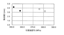
- 6 is a graph showing the relationship between the tensile strength and the overhang height in the metal laminates obtained in Examples 1 to 4.
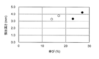
- 6 is a graph showing the relationship between elongation and overhang height in the metal laminates obtained in Examples 1 to 4.
- SEM scanning electron microscope
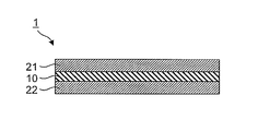
- the metal laminate 1 of the present invention has a first stainless steel layer 21 / magnesium layer 10 / a first stainless steel layer 21 and a second stainless steel layer 22 bonded to both surfaces of a magnesium layer 10.
- the second stainless steel layer 22 has a three-layer structure.
- the metal laminate 1 of the present invention has a tensile strength TS (MPa) of 200 ⁇ TS ⁇ 430, an elongation EL of 10% or more, and surface hardness Hv of the first stainless steel layer 21 and the second stainless steel layer 22. Is 300 or less.
- the lower limit of TS is 220 or more
- the upper limit is preferably 400 or less, more preferably 390 or less, more preferably 365 or less
- EL is preferably 12% or more, more preferably 20% or more
- Hv is Preferably it is 280 or less, More preferably, it is 249 or less.
- the moldability of the metal laminated material 1 will be favorable, and specifically, the overhang height by an Ericksen test is 3 mm or more, Preferably it is 3.2 mm or more, More preferably, it is 3.5 mm or more. High moldability can be obtained. It was impossible to produce a laminate having a hardness Hv of 300 or higher or a TS of 430 MPa or higher as described in the following examples. The reason for this is not clear, but it is presumed that the contact area of the interface with magnesium, which has low formability, could not be secured due to the high hardness and tensile strength of the stainless steel plate or foil.
- the tensile strength TS and the elongation EL are values measured according to JIS Z2241 (metal material tensile test method), and the surface hardness Hv is JIS Z2244 (Vickers hardness test-test method, load 100 gf).
- the value measured according to The overhang height by the Eriksen test is a value measured according to JIS Z2247 (Eriksen test method).
- the average crystal grain size of the first stainless steel layer 21 and the second stainless steel layer 22 is 1.5 ⁇ m to 10 ⁇ m, and the cross section is observed from the sample coordinate system TD (Transverse Direction).
- the number of shear bands crossing a straight line having a length of 10 ⁇ m along the sample coordinate system ND (Normal-Direction) is less than 5.
- the average crystal grain size is more preferably 1.5 ⁇ m to 8.0 ⁇ m, particularly preferably 2.0 ⁇ m to 6.0 ⁇ m.
- the number of shear bands crossing a straight line having a length of 10 ⁇ m is more preferably 3 or less, still more preferably 1 or less, and particularly preferably 0.
- the average crystal grain size was measured for one crystal grain by arbitrarily selecting 30 crystal grains in a cross-sectional observation image by a scanning electron microscope (SEM) from the sample coordinate system TD of the metal laminate.
- SEM scanning electron microscope
- the average value of the major axis and the minor axis is defined as the grain size of the crystal grain, it means the average grain size of the 30 crystal grains.
- the number of shear bands to be traversed is a straight line having a length of 10 ⁇ m along the thickness direction of the metal laminate (sample coordinate system ND) in the cross-sectional observation image by SEM from the sample coordinate system TD of the metal laminate. Is a value obtained by averaging the number of shear bands crossing one straight line with respect to 10 straight lines.
- RD Rolling Direction
- TD Transverse Direction
- ND Normal Direction
- the stainless steel as the material of the first stainless steel layer 21 and the second stainless steel layer 22 is not particularly limited, and plate materials or foils such as SUS304, SUS210, SUS316, SUS316L, and SUS430 can be used.
- the surface hardness Hv of the plate material or foil before joining needs to be 300 or less.
- processing strain is introduced into the stainless steel, and usually the surface hardness Hv increases.
- the hardness of the plate or foil before joining and after joining (the metal laminate 1 of FIG. 1).
- the difference from the hardness in the state (1) is preferably within 100.
- the thickness of the stainless steel plate or foil is usually applicable if it is 0.01 mm or more, and from the viewpoint of mechanical strength and workability of the obtained metal laminate, it is 0.01 mm to 0.6 mm.
- the thickness is preferably 0.01 mm to 0.3 mm, but is not limited to this range.
- the magnesium plate material or foil is not particularly limited, and pure magnesium or a magnesium alloy can be used. Specific examples include AZ31, AZ61, AZ91, LZ91 and the like. Further, the surface hardness Hv of the magnesium plate or foil is appropriately selected in consideration of the above because the moldability of the metal laminated material after the bonding is lowered if it is too large, and conversely if it is too small, handling becomes difficult. The Preferably, 50 ⁇ Hv ⁇ 100, but not limited thereto. Furthermore, the thickness of the magnesium plate or foil is usually 0.01 mm or more, and is applicable from the viewpoint of the mechanical strength and workability of the resulting metal laminate, and should be 0.01 mm to 1 mm. Although preferable, it is not limited to this range.
- a step of sputter etching a first stainless steel plate or foil (hereinafter sometimes referred to as “plate material”) and a step of sputter etching a magnesium plate or foil are performed. Then, the sputter-etched surface of the first stainless steel plate or foil and the magnesium plate or foil is pressed to obtain a first stainless steel layer / magnesium layer two-layer material. Next, the step of sputter-etching the surface of the magnesium layer of the two-layer material and the step of sputter-etching the second stainless steel plate or foil were sputter-etched on the two-layer material and the second stainless steel plate or foil. By pressing the surfaces, a metal laminate 1 having a three-layer structure of first stainless steel layer 21 / magnesium layer 10 / second stainless steel layer 22 as shown in FIG. 1 can be manufactured.
- the sputter etching process is performed, for example, by using a first stainless steel plate or the like and a magnesium plate or the like (the same applies when the sputter etching is performed on the two-layer material and the second stainless steel plate) as a long coil having a width of 100 mm to 600 mm.
- the area of the electrode exposed in the generated plasma can be set to 1/3 or less of the area of the other electrode.
- the grounded electrode is in the form of a cooling roll to prevent the temperature of each conveying material from rising.
- the adsorbed material on the surface is completely removed and a part or all of the oxide film on the surface is removed by sputtering the surface where stainless steel and magnesium are joined under vacuum.
- the oxide film does not necessarily need to be completely removed, and a sufficient bonding force can be obtained even if it remains partially.
- the sputter etching processing time can be significantly reduced compared with the case where the oxide film is completely removed, and the productivity of the metal laminate can be improved.
- the inert gas argon, neon, xenon, krypton, or a mixed gas containing at least one of these can be used.
- the adsorbate on the surface can be completely removed with an etching amount of about 1 nm.
- the sputter etching process for stainless steel can be performed under a vacuum, for example, with a plasma output of 100 W to 10 kW and a line speed of 0.5 m / min to 30 m / min.
- the degree of vacuum at this time is preferably higher in order to prevent re-adsorption on the surface, but it may be, for example, 1 ⁇ 10 ⁇ 5 Pa to 10 Pa.
- the temperature of the stainless steel is preferably kept at room temperature to 150 ° C. from the viewpoint of preventing the softening of magnesium.
- the stainless steel in which the oxide film partially remains on the surface can be obtained by setting the etching amount of the stainless steel to, for example, 1 nm to 10 nm. If necessary, the etching amount may exceed 10 nm.
- the sputter etching process for magnesium can be performed under vacuum, for example, with a plasma output of 100 W to 10 kW and a line speed of 0.5 m / min to 30 m / min.
- the degree of vacuum at this time is preferably higher in order to prevent re-adsorbed substances on the surface, but may be 1 ⁇ 10 ⁇ 5 Pa to 10 Pa.
- magnesium in which a part of the oxide film on the surface remains can be obtained by setting the etching amount of magnesium to 1 nm to 10 nm. If necessary, the etching amount may exceed 10 nm.
- the pressure contact between the first stainless steel plate and the magnesium plate and the pressure contact between the two-layer material and the second stainless steel plate can be performed by roll pressure welding.
- the rolling line load for roll pressure welding is not particularly limited, and can be set, for example, within a range of 0.1 to 10 tf / cm.
- the temperature at the time of joining by roll pressure welding is not particularly limited, and is, for example, from room temperature to 150 ° C.
- the reduction ratio at the time of press contact exceeds 25%, a large amount of processing strain enters, and the moldability of the obtained metal laminate tends to deteriorate, so it is preferably 15% or less, more preferably 10% or less. is there.
- the lower limit value of the rolling reduction is 0%.
- Bonding by roll pressure welding is preferably performed in a non-oxidizing atmosphere, for example, an inert gas atmosphere such as Ar, in order to prevent a reduction in bonding strength between the stainless steel and the magnesium surface due to resorption of oxygen. .
- a non-oxidizing atmosphere for example, an inert gas atmosphere such as Ar, in order to prevent a reduction in bonding strength between the stainless steel and the magnesium surface due to resorption of oxygen.
- the average crystal grain size measured by the same method as in the case of the above metal laminate is 1.5 ⁇ m to 10 ⁇ m, and the length is 10 ⁇ m along the sample coordinate system ND. It is preferred that the number of shear bands across the straight line is less than 5.
- the tensile strength TS (MPa) is 200 ⁇ TS ⁇ 430, and the elongation EL is 10% or more.
- the surface hardness Hv of the stainless steel layer is 300 or less. If the number of shear bands that cross before joining is large, or if the rolling reduction is high, the number of shear bands that cross even after lamination increases, and molding processability may decrease.
- the metal laminate having a three-layer structure obtained by pressure welding is preferably further heat-treated as necessary.
- heat treatment the processing strain of the magnesium layer is removed, and the adhesion between the layers can be improved.
- This heat treatment needs to be performed below the melting point of magnesium.
- the temperature is 590 ° C. or less, preferably 500 ° C. or less. This is to prevent the magnesium from melting.
- the minimum of heat processing temperature shall be 100 degreeC or more, More preferably, it is 150 degreeC or more.
- this heat treatment is preferably performed at a temperature at which the stainless steel metal element is thermally diffused into the magnesium. Bonding power is improved by thermal diffusion.
- the heat treatment can be performed at a temperature of 100 to 590 ° C.
- the metal laminate obtained by thermal diffusion has a high bonding strength and a high reinforcing material hardness, and can prevent magnesium from melting when heated.
- the heat treatment temperature is preferably 150 to 500 ° C. from the viewpoint of further improving the bonding force and at the same time preventing the melting of magnesium.
- the heat treatment time varies depending on the temperature, for example, if it is 300 ° C., it is preferable to hold for about 1 second (not including the temperature rise time) to about 240 minutes.
- the thickness of the metal laminate having a three-layer structure manufactured by the above steps is not particularly limited, but the present invention controls the tensile strength, elongation, and surface hardness of the stainless steel layer within a predetermined range. Therefore, even if it is a thin metal laminated material, it has the feature that a high moldability can be ensured.
- the specific thickness of the metal laminate can be, for example, 50 ⁇ m to 800 ⁇ m, preferably less than 700 ⁇ m, and more preferably less than 600 ⁇ m. Further, in the metal laminate having a three-layer structure, the larger the ratio of the stainless steel layer, the easier the molding processability becomes. However, if the thickness of the magnesium layer is too large with respect to the thickness of the stainless steel layer, the moldability of the metal laminate is deteriorated.
- Example 1 SUS316 and SUS316L were used as the first stainless steel foil and the second stainless steel foil, and AZ31 was used as the magnesium foil. Table 1 shows the characteristic values of each test material.
- the hardness is a micro Vickers hardness meter (load 100 gf)
- the tensile strength and elongation are tensile testers (Autograph AGS-5kNX, manufactured by Shimadzu Corporation)
- the overhang height is mechanical An Erichsen tester ESM-1 (CAP 2 mm, manufactured by Tokyo Henki Tester Co., Ltd.) was used.
- a sputter etching process was performed on the first stainless steel foil and the magnesium foil.
- Sputter etching for the first stainless steel foil was performed under conditions of 0.1 Pa and plasma power of 700 W for 20 minutes
- sputter etching for the magnesium foil was performed under plasma pressure of 700 W and 20 W under 0.1 Pa. It carried out on the conditions for minutes, and the adsorbate of the surface of the 1st stainless steel foil and the magnesium foil was removed completely.
- the first stainless steel foil and the magnesium foil after the sputter etching treatment were joined by roll pressure welding at room temperature at a rolling line load of 2 tf / cm to obtain a two-layer material.
- the surface of the magnesium layer in the two-layer material and the second stainless steel foil were sputter-etched.
- Sputter etching for the two-layer material is performed under conditions of 0.1 Pa and plasma output of 700 W for 20 minutes
- sputter etching for the second stainless steel foil is performed under plasma pressure of 700 W and 20 W under 0.1 Pa. It carried out on condition of a minute, and the adsorbate of the surface of a magnesium layer and the 2nd stainless steel foil was removed completely.
- the magnesium layer of the two-layer material and the foil of the second stainless steel are joined by roll pressure welding at a room temperature at a rolling line load of 2 tf / cm, and a three-layer structure of first stainless steel layer / magnesium layer / second stainless steel layer
- the metal laminated material which has this was manufactured.
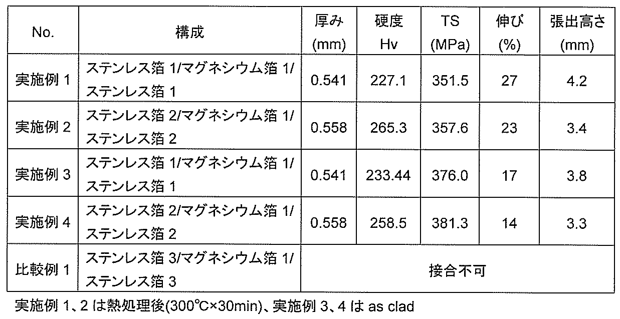
- the resulting metal laminate (as clad) corresponds to Examples 3 and 4.
- the rolling reduction of the finally obtained laminated material was calculated from the following formula 1, and Example 3 was 8% and Example 4 was 6.3%.
- Example 3 and Example 1 and Example 4 and Example 2 revealed that the overhang height was improved by heat treatment, and better moldability was obtained.
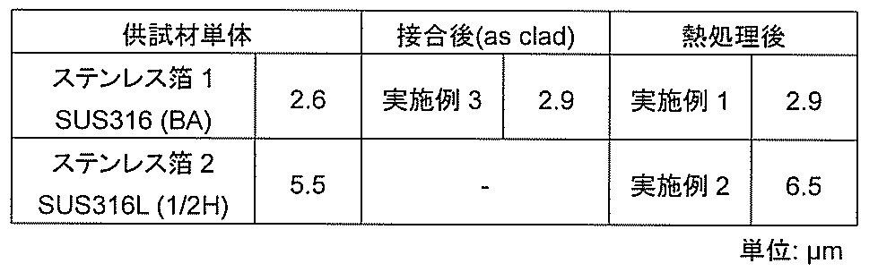
- the average crystal grain size of the stainless steel layer was measured as follows. First, each metal laminate sample was immersed in aqua regia diluted to about 1/3 as a corrosive solution for about 10 to 15 minutes to etch the stainless steel layer. Thereafter, the etched stainless steel layer was subjected to cross-sectional observation from the sample coordinate system TD using a SEM (manufactured by Hitachi High-Technologies Corporation, field emission scanning electron microscope SU8020). The average crystal grain size was calculated from the observed image according to the above definition.
- the average crystal grain size was also measured for the stainless steel foil 1 and the stainless steel foil 2 before joining.
- Table 3 shows the measurement results.
- SEM observation images of the stainless steel foil 1 alone, after joining the stainless steel foil 1 (as clad, corresponding to Example 3), and after joining and heat-treating the stainless steel foil 1 (corresponding to Example 1) are shown in FIG. To C respectively.
- SEM observation images of the stainless steel foil 2 alone and the stainless steel foil 2 after joining and heat treatment are shown in FIGS. 6A and 6B, respectively.
- the portion surrounded by a frame represents a crystal grain.
- the average crystal grain size of the stainless steel layers of the metal laminates of Examples 1 to 3 having good moldability was in the range of 1.5 ⁇ m to 10 ⁇ m.
- the shear band existed and it was difficult to measure the crystal grain size.
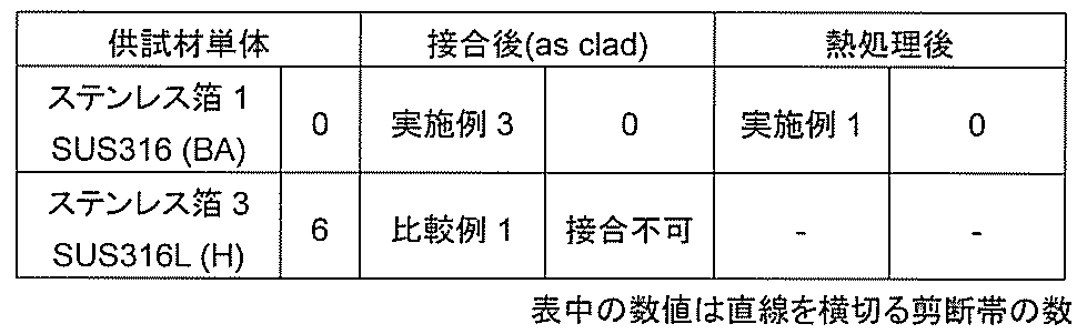
- the number of shear bands crossing a 10 ⁇ m long straight line along the sample coordinate system ND in the cross-sectional observation image from the sample coordinate system TD of the stainless steel layer is calculated as described above. Measured according to definition. The apparatus used for the measurement is the same as that used in the evaluation of the average crystal grain size.
- the number of shear bands was similarly measured for the stainless steel foil 1 and the stainless steel foil before joining.
- Table 4 shows the measurement results.
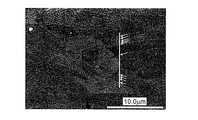
- SEM observation images of the stainless steel foil 1 and the stainless steel foil 3 are shown in FIGS. 7 and 8, respectively. In FIG. 8, the arrow has shown the location where the shear zone has crossed the straight line.
Landscapes
- Chemical & Material Sciences (AREA)
- Engineering & Computer Science (AREA)
- Mechanical Engineering (AREA)
- Materials Engineering (AREA)
- Metallurgy (AREA)
- Organic Chemistry (AREA)
- Physics & Mathematics (AREA)
- Thermal Sciences (AREA)
- Crystallography & Structural Chemistry (AREA)
- Plasma & Fusion (AREA)
- Laminated Bodies (AREA)
- Pressure Welding/Diffusion-Bonding (AREA)
- Metal Rolling (AREA)
- Heat Treatment Of Articles (AREA)
Abstract
Description
(1)第1ステンレス層/マグネシウム層/第2ステンレス層の3層構造を有する金属積層材であって、
引張強度TS(MPa)が、200≦TS≦430であり、伸びELが10%以上であり、第1ステンレス層及び第2ステンレス層の表面硬度Hvが300以下である、前記金属積層材。
(2)第1ステンレス層及び第2ステンレス層の平均結晶粒径が1.5μm~10μmであり、且つ試料座標系TDからの断面観察像において試料座標系NDに沿った長さ10μmの直線を横切る剪断帯の数が5未満である、上記(1)に記載の金属積層材。
(3)上記(1)又は(2)に記載の金属積層材の製造方法であって、
表面硬度Hvが300以下である第1ステンレスの板材もしくは箔をスパッタエッチングする工程と、
表面硬度Hvが50以上のマグネシウムの板材もしくは箔をスパッタエッチングする工程と、
前記第1ステンレスの板材もしくは箔及び前記マグネシウムの板材もしくは箔におけるスパッタエッチングした面を圧接し、第1ステンレス層/マグネシウム層の2層材を得る工程と、
前記2層材のマグネシウム層の面をスパッタエッチングする工程と、
表面硬度Hvが300以下である第2ステンレスの板材もしくは箔をスパッタエッチングする工程と、
前記2層材及び前記第2ステンレスの板材もしくは箔におけるスパッタエッチングした面を圧接し、第1ステンレス層/マグネシウム層/第2ステンレス層の3層構造を有する金属積層材を得る工程と、
を含む、前記金属積層材の製造方法。
(4)スパッタエッチングした面を圧接する際に、圧下率25%以下にて圧接を行う、上記(3)に記載の金属積層材の製造方法。
(5)上記(3)又は(4)に記載の製造方法によって得られた金属積層材を、さらに100~590℃にて熱処理を行う工程を含む、金属積層材の製造方法。
(実施例1~4及び比較例1)
第1ステンレスの箔及び第2ステンレスの箔としてSUS316及びSUS316Lを用い、マグネシウムの箔としてAZ31を用いた。各供試材の特性値を表1に示す。なお、各特性値の測定機器として、硬度はマイクロビッカース硬度計(荷重100gf)、引張強度及び伸びは引張試験機(オートグラフAGS-5kNX、(株)島津製作所製)、張出高さは機械式エリクセン試験機ESM-1(CAP2mm、(株)東京衡機試験機製)を用いた。

上記工程によって得られた金属積層材を、さらに300℃で30分間熱処理した。この熱処理を行った金属積層材は実施例1及び2に対応する。製造した各金属積層材について測定した特性値を表2にまとめて示す。また、金属積層材における表面硬度Hv、引張強度TS及び伸びとエリクセン試験による張出高さとの関係を、それぞれ図2~図4に示す。なお、ステンレス層、マグネシウム層いずれも表面硬度は荷重100gfにて測定した。
(平均結晶粒径の評価)
上記実施例1~3の金属積層材について、ステンレス層の平均結晶粒径を以下のようにして測定した。まず、各金属積層材のサンプルを、腐食液として約1/3に希釈した王水に10~15分程度浸漬し、ステンレス層をエッチングした。その後、エッチングを施した各サンプルのステンレス層を試料座標系TDからSEM(日立ハイテクノロジーズ社製、電解放出型走査電子顕微鏡SU8020)にて断面観察を行った。観察像から上述の定義に従って平均結晶粒径を算出した。また、参考のため、接合前のステンレス箔1及びステンレス箔2についても平均結晶粒径を測定した。測定結果を表3に示す。また、ステンレス箔1単体、ステンレス箔1を接合後(as clad、実施例3に相当)、及びステンレス箔1を接合し熱処理した後(実施例1に相当)のSEM観察像を図5のA~Cにそれぞれ示す。さらに、ステンレス箔2単体、及びステンレス箔2を接合し熱処理した後(実施例2に相当)のSEM観察像を図6のA~Bにそれぞれ示す。図中、枠で囲まれた部分は結晶粒を表している。
(剪断帯の評価)
次に、上記実施例1及び3の金属積層材について、ステンレス層の試料座標系TDからの断面観察像において試料座標系NDに沿った長さ10μmの直線を横切る剪断帯の数を、上述の定義に従って測定した。測定に用いた装置は、上記の平均結晶粒径の評価において用いたものと同一である。また、参考のため、接合前のステンレス箔1及びステンレス箔についても同様に剪断帯の数を測定した。測定結果を表4に示す。さらに、ステンレス箔1単体、及びステンレス箔3単体のSEM観察像をそれぞれ図7及び図8に示す。図8中、矢印は、剪断帯が直線を横切っている箇所を示している。
10 マグネシウム層
21 第1ステンレス層
22 第2ステンレス層
本明細書で引用した全ての刊行物、特許及び特許出願はそのまま引用により本明細書に組み入れられるものとする。
Claims (5)
- 第1ステンレス層/マグネシウム層/第2ステンレス層の3層構造を有する金属積層材であって、
引張強度TS(MPa)が、200≦TS≦430であり、伸びELが10%以上であり、第1ステンレス層及び第2ステンレス層の表面硬度Hvが300以下である、前記金属積層材。 - 第1ステンレス層及び第2ステンレス層の平均結晶粒径が1.5μm~10μmであり、且つ試料座標系TDからの断面観察像において試料座標系NDに沿った長さ10μmの直線を横切る剪断帯の数が5未満である、請求項1に記載の金属積層材。
- 請求項1又は2に記載の金属積層材の製造方法であって、
表面硬度Hvが300以下である第1ステンレスの板材もしくは箔をスパッタエッチングする工程と、
表面硬度Hvが50以上のマグネシウムの板材もしくは箔をスパッタエッチングする工程と、
前記第1ステンレスの板材もしくは箔及び前記マグネシウムの板材もしくは箔におけるスパッタエッチングした面を圧接し、第1ステンレス層/マグネシウム層の2層材を得る工程と、
前記2層材のマグネシウム層の面をスパッタエッチングする工程と、
表面硬度Hvが300以下である第2ステンレスの板材もしくは箔をスパッタエッチングする工程と、
前記2層材及び前記第2ステンレスの板材もしくは箔におけるスパッタエッチングした面を圧接し、第1ステンレス層/マグネシウム層/第2ステンレス層の3層構造を有する金属積層材を得る工程と、
を含む、前記金属積層材の製造方法。 - スパッタエッチングした面を圧接する際に、圧下率25%以下にて圧接を行う、請求項3に記載の金属積層材の製造方法。
- 請求項3又は4に記載の製造方法によって得られた金属積層材を、さらに100~590℃にて熱処理を行う工程を含む、金属積層材の製造方法。
Priority Applications (4)
| Application Number | Priority Date | Filing Date | Title |
|---|---|---|---|
| CN201680056608.3A CN108055835A (zh) | 2015-09-30 | 2016-09-30 | 金属层叠材料及其制造方法 |
| US15/764,398 US20180265990A1 (en) | 2015-09-30 | 2016-09-30 | Metal laminate material and method for producing the same |
| JP2017543623A JPWO2017057698A1 (ja) | 2015-09-30 | 2016-09-30 | 金属積層材及びその製造方法 |
| KR1020187007717A KR20180063066A (ko) | 2015-09-30 | 2016-09-30 | 금속 적층재 및 그 제조 방법 |
Applications Claiming Priority (2)
| Application Number | Priority Date | Filing Date | Title |
|---|---|---|---|
| JP2015192915 | 2015-09-30 | ||
| JP2015-192915 | 2015-09-30 |
Publications (1)
| Publication Number | Publication Date |
|---|---|
| WO2017057698A1 true WO2017057698A1 (ja) | 2017-04-06 |
Family
ID=58427653
Family Applications (1)
| Application Number | Title | Priority Date | Filing Date |
|---|---|---|---|
| PCT/JP2016/079071 Ceased WO2017057698A1 (ja) | 2015-09-30 | 2016-09-30 | 金属積層材及びその製造方法 |
Country Status (5)
| Country | Link |
|---|---|
| US (1) | US20180265990A1 (ja) |
| JP (1) | JPWO2017057698A1 (ja) |
| KR (1) | KR20180063066A (ja) |
| CN (1) | CN108055835A (ja) |
| WO (1) | WO2017057698A1 (ja) |
Cited By (3)
| Publication number | Priority date | Publication date | Assignee | Title |
|---|---|---|---|---|
| WO2018181721A1 (ja) * | 2017-03-29 | 2018-10-04 | 東洋鋼鈑株式会社 | 圧延接合体 |
| JP2019005805A (ja) * | 2017-06-20 | 2019-01-17 | 東洋鋼鈑株式会社 | 圧延接合体 |
| JP2019181514A (ja) * | 2018-04-10 | 2019-10-24 | 東洋鋼鈑株式会社 | 圧延接合体及び圧延接合体の製造方法 |
Families Citing this family (4)
| Publication number | Priority date | Publication date | Assignee | Title |
|---|---|---|---|---|
| JP6543439B2 (ja) * | 2014-04-01 | 2019-07-10 | 東洋鋼鈑株式会社 | 金属積層材の製造方法 |
| CN107677232B (zh) * | 2017-09-21 | 2020-03-31 | 京东方科技集团股份有限公司 | 一种晶粒尺寸测量方法及装置、多晶硅薄膜的生产方法 |
| EP3778237A1 (en) * | 2019-08-14 | 2021-02-17 | ABB Schweiz AG | Combined additive and substractive manufacturing of bladed rotors |
| CN113275381A (zh) * | 2021-06-29 | 2021-08-20 | 湖南科技大学 | 一种制备金属复合板的热轧轧制复合方法 |
Citations (4)
| Publication number | Priority date | Publication date | Assignee | Title |
|---|---|---|---|---|
| JPH0195883A (ja) * | 1987-10-08 | 1989-04-13 | Kawasaki Steel Corp | ステンレス鋼−アルミニウムクラッド材の製造方法 |
| JP2004351460A (ja) * | 2003-05-29 | 2004-12-16 | Neomax Co Ltd | アルミニウム・ニッケル・ステンレス鋼クラッド材、その製造方法および電池用ケース |
| JP2007111830A (ja) * | 2005-10-21 | 2007-05-10 | Asahi Kasei Chemicals Corp | 工作機械等の駆動用ステージ部材 |
| JP2010155357A (ja) * | 2008-12-26 | 2010-07-15 | Osaka Prefecture Univ | マグネシウム合金クラッド材およびその製造方法 |
Family Cites Families (6)
| Publication number | Priority date | Publication date | Assignee | Title |
|---|---|---|---|---|
| JPS5323927A (en) | 1976-08-13 | 1978-03-06 | Mitsubishi Chem Ind Ltd | Trihaloalkyl carbonic acid esters of saccharides |
| JPS5372469A (en) | 1976-12-10 | 1978-06-27 | Hitachi Ltd | Manufacture for semiconductor |
| CN2431111Y (zh) * | 2000-06-01 | 2001-05-23 | 朱金龙 | 夹层复合金属板 |
| JP2006088435A (ja) | 2004-09-22 | 2006-04-06 | Neomax Material:Kk | マグネシウム系金属クラッド板 |
| CN101422797A (zh) * | 2007-10-31 | 2009-05-06 | 中国科学院金属研究所 | 一种金属板材成形方法 |
| CN101459120B (zh) * | 2007-12-13 | 2010-08-11 | 中芯国际集成电路制造(上海)有限公司 | 去除互连金属层表面氧化膜的方法 |
-
2016
- 2016-09-30 WO PCT/JP2016/079071 patent/WO2017057698A1/ja not_active Ceased
- 2016-09-30 JP JP2017543623A patent/JPWO2017057698A1/ja active Pending
- 2016-09-30 US US15/764,398 patent/US20180265990A1/en not_active Abandoned
- 2016-09-30 KR KR1020187007717A patent/KR20180063066A/ko not_active Withdrawn
- 2016-09-30 CN CN201680056608.3A patent/CN108055835A/zh active Pending
Patent Citations (4)
| Publication number | Priority date | Publication date | Assignee | Title |
|---|---|---|---|---|
| JPH0195883A (ja) * | 1987-10-08 | 1989-04-13 | Kawasaki Steel Corp | ステンレス鋼−アルミニウムクラッド材の製造方法 |
| JP2004351460A (ja) * | 2003-05-29 | 2004-12-16 | Neomax Co Ltd | アルミニウム・ニッケル・ステンレス鋼クラッド材、その製造方法および電池用ケース |
| JP2007111830A (ja) * | 2005-10-21 | 2007-05-10 | Asahi Kasei Chemicals Corp | 工作機械等の駆動用ステージ部材 |
| JP2010155357A (ja) * | 2008-12-26 | 2010-07-15 | Osaka Prefecture Univ | マグネシウム合金クラッド材およびその製造方法 |
Cited By (6)
| Publication number | Priority date | Publication date | Assignee | Title |
|---|---|---|---|---|
| WO2018181721A1 (ja) * | 2017-03-29 | 2018-10-04 | 東洋鋼鈑株式会社 | 圧延接合体 |
| JP2019005805A (ja) * | 2017-06-20 | 2019-01-17 | 東洋鋼鈑株式会社 | 圧延接合体 |
| JP2019181514A (ja) * | 2018-04-10 | 2019-10-24 | 東洋鋼鈑株式会社 | 圧延接合体及び圧延接合体の製造方法 |
| CN112020406A (zh) * | 2018-04-10 | 2020-12-01 | 东洋钢钣株式会社 | 轧制接合体及轧制接合体的制造方法 |
| CN112020406B (zh) * | 2018-04-10 | 2022-06-24 | 东洋钢钣株式会社 | 轧制接合体及轧制接合体的制造方法 |
| JP7171216B2 (ja) | 2018-04-10 | 2022-11-15 | 東洋鋼鈑株式会社 | 圧延接合体及び圧延接合体の製造方法 |
Also Published As
| Publication number | Publication date |
|---|---|
| US20180265990A1 (en) | 2018-09-20 |
| JPWO2017057698A1 (ja) | 2018-09-06 |
| CN108055835A (zh) | 2018-05-18 |
| KR20180063066A (ko) | 2018-06-11 |
Similar Documents
| Publication | Publication Date | Title |
|---|---|---|
| JP6865172B2 (ja) | 金属積層材及びその製造方法 | |
| WO2017057698A1 (ja) | 金属積層材及びその製造方法 | |
| JP6381944B2 (ja) | 金属積層材の製造方法 | |
| WO2011155379A1 (ja) | アルミニウム銅クラッド材 | |
| CN106102978A (zh) | 金属层叠材料的制造方法 | |
| JP7085419B2 (ja) | 圧延接合体及びその製造方法 | |
| JP6637200B2 (ja) | 圧延接合体及びその製造方法 | |
| JP2022145789A (ja) | 圧延接合体及び圧延接合体の製造方法 | |
| JP6995712B2 (ja) | 圧延接合体及びその製造方法 | |
| JP7162960B2 (ja) | 圧延接合体及びその製造方法、並びに電子機器用の放熱補強部材 | |
| JP6375048B1 (ja) | 圧延接合体 | |
| JP6813961B2 (ja) | 銅及びマグネシウムからなる金属積層材及びその製造方法 | |
| WO2018181721A1 (ja) | 圧延接合体 | |
| WO2020031956A1 (ja) | 圧延接合体及びその製造方法、並びに電子機器用の放熱補強部材 | |
| CN118973754A (zh) | 压延接合体及其制造方法 | |
| JPH05386A (ja) | アルミニウム/インバー/アルミニウムクラツド材の製造方法 | |
| JP2019018221A (ja) | 積層薄板およびその製造方法 | |
| JP2019034453A (ja) | 積層薄板の製造方法および積層薄板 |
Legal Events
| Date | Code | Title | Description |
|---|---|---|---|
| 121 | Ep: the epo has been informed by wipo that ep was designated in this application |
Ref document number: 16851867 Country of ref document: EP Kind code of ref document: A1 |
|
| ENP | Entry into the national phase |
Ref document number: 20187007717 Country of ref document: KR Kind code of ref document: A |
|
| ENP | Entry into the national phase |
Ref document number: 2017543623 Country of ref document: JP Kind code of ref document: A |
|
| WWE | Wipo information: entry into national phase |
Ref document number: 15764398 Country of ref document: US |
|
| NENP | Non-entry into the national phase |
Ref country code: DE |
|
| 122 | Ep: pct application non-entry in european phase |
Ref document number: 16851867 Country of ref document: EP Kind code of ref document: A1 |