WO2017057686A1 - 磁気ディスク用ガラス基板、磁気ディスク、ガラス基板中間体、及び磁気ディスク用ガラス基板の製造方法 - Google Patents
磁気ディスク用ガラス基板、磁気ディスク、ガラス基板中間体、及び磁気ディスク用ガラス基板の製造方法 Download PDFInfo
- Publication number
- WO2017057686A1 WO2017057686A1 PCT/JP2016/079037 JP2016079037W WO2017057686A1 WO 2017057686 A1 WO2017057686 A1 WO 2017057686A1 JP 2016079037 W JP2016079037 W JP 2016079037W WO 2017057686 A1 WO2017057686 A1 WO 2017057686A1
- Authority
- WO
- WIPO (PCT)
- Prior art keywords
- glass substrate
- magnetic disk
- roughness
- glass
- magnetic
- Prior art date
- Legal status (The legal status is an assumption and is not a legal conclusion. Google has not performed a legal analysis and makes no representation as to the accuracy of the status listed.)
- Ceased
Links
Images





Classifications
-
- G—PHYSICS
- G11—INFORMATION STORAGE
- G11B—INFORMATION STORAGE BASED ON RELATIVE MOVEMENT BETWEEN RECORD CARRIER AND TRANSDUCER
- G11B5/00—Recording by magnetisation or demagnetisation of a record carrier; Reproducing by magnetic means; Record carriers therefor
- G11B5/84—Processes or apparatus specially adapted for manufacturing record carriers
- G11B5/8404—Processes or apparatus specially adapted for manufacturing record carriers manufacturing base layers
-
- G—PHYSICS
- G11—INFORMATION STORAGE
- G11B—INFORMATION STORAGE BASED ON RELATIVE MOVEMENT BETWEEN RECORD CARRIER AND TRANSDUCER
- G11B5/00—Recording by magnetisation or demagnetisation of a record carrier; Reproducing by magnetic means; Record carriers therefor
- G11B5/62—Record carriers characterised by the selection of the material
- G11B5/73—Base layers, i.e. all non-magnetic layers lying under a lowermost magnetic recording layer, e.g. including any non-magnetic layer in between a first magnetic recording layer and either an underlying substrate or a soft magnetic underlayer
- G11B5/739—Magnetic recording media substrates
- G11B5/73911—Inorganic substrates
- G11B5/73921—Glass or ceramic substrates
-
- G—PHYSICS
- G11—INFORMATION STORAGE
- G11B—INFORMATION STORAGE BASED ON RELATIVE MOVEMENT BETWEEN RECORD CARRIER AND TRANSDUCER
- G11B5/00—Recording by magnetisation or demagnetisation of a record carrier; Reproducing by magnetic means; Record carriers therefor
- G11B5/84—Processes or apparatus specially adapted for manufacturing record carriers
Definitions
- the present invention relates to a glass substrate for a magnetic disk, a magnetic disk, and a glass substrate intermediate serving as a base plate of the glass substrate for a magnetic disk.
- a personal computer, a notebook personal computer, or a DVD (Digital Versatile Disc) recording device has a built-in hard disk device for data recording.
- a hard disk device used in a portable computer such as a notebook personal computer
- a magnetic disk having a magnetic film hereinafter also referred to as a magnetic layer
- a glass substrate is used as the magnetic disk substrate.
- a magnetic disk is recorded on the magnetic disk surface by projecting only the recording / reproducing element (at least one of the recording element and the reproducing element) to the medium surface side.
- DFH Dynamic Flying Height
- DFH head which has a shorter distance from the reproducing element (hereinafter referred to as the flying distance), for example, a flying distance of about 5 nm. Has been.
- the end surface of the glass substrate has a side wall surface of the glass substrate and a chamfered surface provided between the side wall surface and the main surface.
- a glass substrate having no pit defects recessed in the chamfered surface is known (Patent Document 1).
- the glass substrate was obtained by chamfering with a grindstone to which diamond abrasive grains were fixed, and then performing end surface polishing using a polishing brush, and observed after etching the surface of the chamfered surface of the glass substrate by 5 ⁇ m.
- a heater for controlling the flying distance by applying heat to the recording / reproducing element and controlling the flying distance is provided. Recently, in order to further shorten the flying distance, the flying distance is controlled.
- An HDI (Head Disk Interface) sensor has been mounted on a DFH head as a functional element for performing with high accuracy.
- the protrusion amount of at least one of the recording element and the reproducing element is controlled based on a signal from the HDI sensor.
- the DFH head equipped with this HDI sensor has made it possible for the first time to perform stable recording / reproduction for a long time even when the distance between the recording / reproducing element and the magnetic disk is as extremely small as 1 nm or less.
- the present invention provides a magnetic disk glass substrate, a magnetic disk, a glass substrate intermediate, and a magnetic disk that do not interfere with recording / reproducing of the magnetic disk even under flying conditions of a recording / reproducing element having a smaller flying distance than conventional ones.
- An object of the present invention is to provide a method for manufacturing a glass substrate.
- One embodiment of the present invention is a glass substrate for a magnetic disk containing an alkaline earth metal component as a glass composition.
- the magnetic disk glass substrate is A glass substrate for a magnetic disk containing an alkaline earth metal component as a glass composition,
- the end surface of the glass substrate is a mirror surface, When the load factor of the roughness cross-sectional area is 50% in the load factor curve of the roughness cross-sectional area obtained when measuring the surface roughness of the end surface after etching the end surface by 2.5 ⁇ m.
- a surface having a roughness percentage of 40% or more is provided.
- the roughness percentage is preferably 50% or more.
- the roughness percentage is 60% or less.
- the arithmetic average surface roughness on the mirror surface is preferably 0.015 ⁇ m or less.
- the glass transition point of the glass constituting the glass substrate for magnetic disk is preferably 700 ° C. or higher.
- the end surface of the glass substrate has a side wall surface and a chamfered surface between the main surface of the glass substrate and the side wall surface, and the side wall surface has a surface roughness percentage of 40% or more. It is preferable that
- the glass constituting the glass substrate for magnetic disk is preferably alkali-free glass.
- the glass substrate is preferably a glass substrate for a magnetic disk mounted on a hard disk drive together with a magnetic head having a DFH (Disk Flying Height) function.
- DFH disk Flying Height
- the glass substrate is preferably a glass substrate used for a magnetic disk for energy-assisted magnetic recording.
- another aspect of the present invention is a magnetic disk having at least a magnetic film on the surface of the magnetic disk glass substrate.
- Yet another embodiment of the present invention is a glass substrate intermediate that includes an alkaline earth metal component as a glass composition and serves as a base plate of a magnetic disk glass substrate.
- the glass substrate intermediate is The end surface of the glass substrate intermediate is a mirror surface, When the load factor of the roughness cross-sectional area is 50% in the load factor curve of the roughness cross-sectional area obtained when measuring the surface roughness of the end surface after etching the end surface by 2.5 ⁇ m. A surface having a roughness percentage of 40% or more is provided.
- the roughness percentage is preferably 50% or more.
- the roughness percentage is 60% or less.
- the glass constituting the glass substrate intermediate is preferably alkali-free glass.
- still another aspect of the present invention is a method for manufacturing a glass substrate for a magnetic disk that performs an end surface polishing treatment of the glass substrate.
- the end surface polishing treatment in the manufacturing method in the load factor curve of the roughness cross-sectional area obtained when measuring the surface roughness of the end surface after etching the end surface of the glass substrate to 2.5 ⁇ m, roughness cutting The end face is polished so that the percentage of roughness when the area load factor is 50% is 40% or more.
- Still another embodiment of the present invention is also a method for manufacturing a glass substrate for a magnetic disk that performs an end surface polishing treatment of the glass substrate.
- at least polishing treatment is performed on the main surface of the glass substrate intermediate.
- the occurrence of corrosion on the end surface of the glass substrate can be suppressed.
- the flying distance of the recording / reproducing element is smaller than that of the prior art, there is no problem in recording / reproducing of the magnetic disk, and a decrease in the S / N ratio of the reproduced signal can be suppressed.
- FIG. 1 It is a figure which shows the external appearance shape of the glass substrate for magnetic discs of this embodiment. It is an expanded sectional view of the end surface of the glass substrate for magnetic disks of this embodiment. It is a figure explaining the load factor curve of the roughness cross-sectional area of a glass substrate. It is a figure explaining the load factor of roughness cross-sectional area (cross-sectional length).
- (A)-(d) is a figure which shows the waveform of various one-dimensional surface shape, and the load factor curve of the roughness cross-section length obtained at this time. It is a figure explaining the method of calculating
- the inventor of the present application investigated a glass substrate in which the S / N ratio of the reproduction signal is reduced under a flying condition in which the flying distance of the recording / reproducing element of the magnetic head is 1 nm or less. It has been found that a substance caused by corrosion (elution of glass component) that does not occur if polished is formed on the end face. This corrosion-derived substance is considered to have moved to the main surface and further adhered to the recording / reproducing element.
- the end surface of the glass substrate is mirror-finished, the surface of the end surface is damaged by thermal shock during film formation during magnetic disk production, etc., and latent cracks formed by shape processing or end surface polishing It is considered that the cracks were manifested and cracks were manifested, and corrosion in which some of the glass components, for example, alkaline earth metal components such as magnesium and calcium, were eluted from the manifested cracks occurred.
- the eluted alkaline earth metal component may react with carbon dioxide in the air to produce carbonates such as magnesium carbonate and calcium carbonate.
- a glass substrate used for a magnetic disk for an energy-assisted magnetic recording method such as HAMR (Heat Assisted Magnetic Recording) for recording information by locally heating the magnetic disk using a laser beam or the like
- HAMR Heat Assisted Magnetic Recording
- the occurrence of corrosion must be further suppressed.
- the inventor of the present application has devised the surface shape of the end face of the glass substrate and the occurrence of the corrosion, and as a result, has come up with the following technique.
- arithmetic mean roughness Ra and maximum height Rz as used in this specification is a value based on JIS B0601: 2001.
- ⁇ Measurement of the surface shape of the end face of the glass substrate to obtain the load factor of the roughness cross-sectional area, the arithmetic average roughness Ra, and the maximum height Rz is performed in an evaluation area of 50 ⁇ m square using a laser microscope. Is performed under the following conditions. Observation magnification: 3000 times Measuring pitch in the height direction (Z axis): 0.01 ⁇ m, Cut-off value ⁇ s: 0.25 ⁇ m, Cut-off value ⁇ c: 80 ⁇ m.
- the resolution in the height direction is preferably 1 nm or less. In this embodiment, the observation magnification is 3000 times, but the observation magnification is appropriately selected in the range of about 1000 to 3000 times depending on the size of the measurement surface.
- the magnetic disk has a donut shape in which a disk-shaped central portion is cut out concentrically, and rotates around the center of the ring.
- the magnetic disk includes a glass substrate and at least a magnetic layer (magnetic film).
- a magnetic layer magnetic film
- an adhesion layer, a soft magnetic layer, a nonmagnetic underlayer, a perpendicular magnetic recording layer, a protective layer, a lubricating layer, and the like are formed.
- the adhesion layer for example, a Cr alloy or the like is used.
- the adhesion layer functions as an adhesion layer with the glass substrate.
- the soft magnetic layer for example, a CoTaZr alloy or the like is used.
- nonmagnetic underlayer for example, a granular nonmagnetic layer is used.
- a granular magnetic layer is used for the perpendicular magnetic recording layer.
- a material made of hydrogen carbon is used for the protective layer.
- a fluorine-based resin or the like is used for the lubricating layer.
- the magnetic disk is formed by using an in-line type sputtering apparatus on both main surfaces of a glass substrate with a CrTi adhesion layer, a CoTaZr / Ru / CoTaZr soft magnetic layer, a CoCrSiO 2 non-magnetic granular underlayer, CoCrPt—SiO 2.
- a granular magnetic layer of TiO 2 and a hydrogenated carbon protective film are sequentially formed. Further, a perfluoropolyether lubricating layer is formed on the formed uppermost layer by dipping.
- Aluminosilicate glass, soda lime glass, borosilicate glass, or the like can be used as the material for the magnetic disk glass substrate in the present embodiment.
- amorphous aluminosilicate glass can be suitably used in that it can easily reduce the flatness, waviness, and roughness of the main surface and can produce a glass substrate for a magnetic disk that is excellent in substrate strength.
- Aluminosilicate glass is preferable because it can be chemically strengthened.
- Glass composition 1 Although the composition of the glass substrate of the present embodiment is not limited, the glass substrate of the present embodiment is preferably converted to oxide standards and expressed in mass%, SiO 2 40-61%, Al 2 O 3 15-23.5%, MgO 2-20%, CaO 0.1 to 40%, [SiO 2 ] + 0.43 ⁇ [Al 2 O 3 ] + 0.59 ⁇ [CaO] ⁇ 74.6 ⁇ 0, and [SiO 2 ] + 0.21 ⁇ [MgO] + 1.16 ⁇ [CaO] ⁇ 83.0 ⁇ 0 Is an amorphous aluminosilicate glass having a composition of alkali-free glass. The above [] is the content (mass%) of the glass component in []. Hereinafter, the above is also referred to as glass composition 1.
- Glass composition 2 (Glass composition 2) Moreover, the following composition is also mentioned as another preferable glass composition. That is, in terms of mass%, converted to oxide standards, SiO 2 64 to 72%, Al 2 O 3 17-22%, MgO 1-8%, CaO 4 to 15.5%, 0.20 ⁇ [MgO] / ([MgO] + [CaO]) ⁇ 0.41 This is an amorphous aluminosilicate glass having a glass composition.
- the glass substrate of this embodiment contains any of alkaline earth metal components such as MgO, CaO, and SrO as an essential component of the glass composition.
- the alkali metal component Li 2 O, Na 2 O , K 2 O
- the alkali metal component may include for, preferably if it is desired to increase the Tg to reduce the content so as not to more included preferable.
- elution of alkali metal components may be a concern depending on the glass composition, but the elution risk is reduced by reducing the content to zero (non-alkali glass). can do.
- the glass transition point (Tg) is 600 ° C. or higher.
- the glass transition point is more preferably 700 ° C. or higher, and further preferably 750 ° C. or higher.
- the glass transition point is preferably set to 700 ° C. or higher because it can withstand the heat treatment in the entire temperature range of 500 to 700 ° C. described above.
- Such a glass substrate is suitable as a glass substrate used for a magnetic disk for energy-assisted magnetic recording.
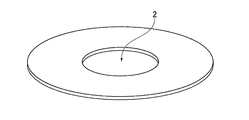
- FIG. 1 is a view showing the external shape of the magnetic disk glass substrate of the present embodiment.
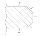
- FIG. 2 is an enlarged cross-sectional view of the outer peripheral side end face of the magnetic disk glass substrate.
- the glass substrate for a magnetic disk in this embodiment is a donut-shaped thin glass substrate in which an inner hole 2 is formed.
- the size (diameter) of the glass substrate does not matter.
- the glass substrate can be used for a nominal 1.8 to 3.5 inch size substrate, for example.
- the plate thickness is not particularly limited, and can be, for example, 0.3 to 3 mm. As shown in FIG.
- the glass substrate of the present embodiment includes a pair of main surfaces 1p, a side wall surface 1t of the glass substrate extending perpendicularly to the pair of main surfaces 1p, and between the side wall surface 1t and the main surface 1p.
- a chamfered surface 1c extending from the side wall surface 1t with an inclination to the side wall surface 1t and connected to the main surface 1p.
- a side wall surface and a chamfered surface are similarly formed on the inner peripheral side end surface of the glass substrate.
- a part or all of the chamfered surface may be formed in an arc shape in a sectional view.
- the glass substrate of the present embodiment has a shape that satisfies the following two requirements 1 and 2 with respect to the surface shape of at least one of the side wall surface and the chamfered surface.
- the end surface of the glass substrate is a mirror surface.
- the load factor of the roughness cross-sectional area is 50% in the load factor curve of the roughness cross-sectional area obtained when the surface roughness of the end surface after wet etching is 2.5 ⁇ m and wet etching is performed on the glass substrate.
- the end face of the glass substrate is provided with a roughness percentage of 40% or more.
- the end surface of the glass substrate of requirement 1 is a mirror surface when the end surface of the glass substrate is polished and the end surface reflects an image of an object like a mirror and displays an image on the surface.
- a mirror surface it is preferable that arithmetic mean roughness Ra of the surface roughness in an end surface is 0.015 micrometer or less, for example.
- the arithmetic average roughness Ra at the end face is larger than 0.015 ⁇ m, the foreign matter (fine particles) is likely to adhere to the surface by capturing the foreign matter in the concave portion on the surface.
- the maximum height Rz of the surface roughness at the end face is 0.15 ⁇ m or less.
- the maximum height Rz By setting the maximum height Rz to 0.15 ⁇ m or less, the depth of the streak-like grooves generated on the end surface becomes shallow, so that fine particles such as colloidal silica used for polishing hardly adhere (residual) to the surface. More preferably, the arithmetic average roughness Ra is 0.015 ⁇ m or less, and the maximum height Rz is preferably 0.15 ⁇ m or less.
- the roughness percentage of requirement 2 is the load factor curve of the roughness cross-sectional area of the end face (side wall surface and / or chamfered surface) described below. It is requested from.
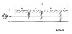
- FIG. 3 is a diagram illustrating a load factor curve of the roughness cross-sectional area of the side wall surface and / or the chamfered surface. Note that the load factor curve of the roughness cross-sectional area is also called a bearing curve.
- roughness percentage refers to the surface that forms the macroscopic shape of the surface at a certain height in the measurement result of the surface shape of the surface near the surface of the target object (or measurement data of the surface shape).
- the “roughness cross-section load factor” is the area of the cutting surface that cuts the region near the surface at a specific cutting level, that is, the area of the area near the surface of the object that exists on the cutting surface (that is, cutting) This is a value expressed as a percentage with respect to the area of the region near the surface of the object when viewed from the direction orthogonal to the surface, not the surface area along the unevenness of the surface.
- the “roughness cross-sectional area load factor” is the lengths L 1 , L 2 , L of the region that cuts the region near the surface of the object relative to the cutting length L 0 .
- FIG. 4 is a diagram for explaining the load factor of the roughness cross-sectional area.
- “Roughness cross-sectional area load factor curve” means that for the target surface vicinity area, the vertical axis is the axis of roughness percentage and the horizontal axis is the axis of the load ratio of roughness cross-sectional area. It is a curve showing the relationship.
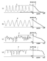
- FIGS. 5A to 5D are diagrams showing a plurality of one-dimensional surface shape waveforms c to f and load factor curves C to F of the roughness cross-sectional length obtained at this time.
- a load factor curve having a roughness cross-section length is obtained in order to obtain a load factor curve having a one-dimensional waveform.
- It is a load factor curve obtained by examining a cross-sectional area.
- the load factor curve C advances from 0% to 100% in roughness (FIG. 5).
- the load factor is a curve that gently rises (goes to the right in the horizontal axis in the figure).
- the load factor curve F has a roughness percentage.
- the load factor is a curve that rapidly increases (goes to the right in the horizontal axis in the drawing) when going from 0% to 100% (going down in the vertical axis in the drawing). As shown in FIG.
- the load factor curve D progresses from a roughness percentage of 0% to 100% (the vertical axis in the figure).
- the gradient of the increase in load factor (rightward in the horizontal axis in the figure) is a substantially constant curve, and the gradient is intermediate between the gradient of the load factor curve C and the gradient of the load factor curve F. It is. Therefore, it is possible to grasp the shape of the surface shape from the load factor curve.
- a load factor curve of the surface shape of the end surface of the glass substrate with respect to the end surface after wet etching is obtained by 2.5 ⁇ m.
- This surface shape data is obtained by measuring the surface shape of the end surface after wet etching.
- the percentage of roughness when the load factor of the roughness cross-sectional area is 50% is 40% or more.
- the roughness percentage when the load factor of the roughness cross-sectional area is 50% is 50% or more.
- the end surface of the glass substrate of the present embodiment has a surface shape in which the roughness percentage is 40% or more when the end surface of the glass substrate is wet-etched.
- the shape processing for forming the side wall surface 1t and the chamfered surface 1c (see FIG. 2) is used to determine the surface shape of the end surface of the glass substrate using the value of the roughness percentage of the surface shape of the end surface after the wet etching. This is because a latent crack is sometimes formed in the vicinity of the surface of the end face of the glass substrate, and a gap between the latent cracks is widened by wet etching, and the latent crack becomes apparent.
- the percentage of roughness when the load factor of the roughness cross-sectional area of the surface shape of the end face after wet etching is 50% is 40% or more.
- the end face after the wet etching has a surface shape as shown in FIG. 5B instead of a surface shape as shown in FIG. That is, it means that a concave portion such as a crack as shown in FIG.
- the surface shape of the end face is determined by the value of the roughness percentage when the load factor of the roughness cross-sectional area is 50%.
- the shape of the load factor curve can be known from this value, and the surface shape of the end face after wet etching is further determined. It is because it can know precisely.
- the roughness percentage when the load factor of the roughness cross-sectional area is 50% is 40% or more
- the load factor curve B When the load factor of the roughness cross-sectional area is 50%, the roughness percentage is less than 40%.
- the surface shape of the end surface showing the load curve A is close to the surface shape in which the concave portion and the convex portion are included in substantially the same ratio as shown in FIG.
- Recesses such as cracks as shown in FIGS. 5C and 5D are close to a surface shape that has developed from a substantially constant surface level at an interval.
- the requirement 2 means that even if the end face is wet etched, there are few latent cracks that appear. Therefore, in the glass substrate that satisfies the requirements 1 and 2, there is little adhesion of fine particles to the end face, and since there are few latent cracks, the latent cracks spread due to the thermal shock during the film forming process when manufacturing the magnetic disk. Even if latent cracks become apparent, few cracks have become apparent. Therefore, the occurrence of corrosion in the glass substrate is suppressed. That is, the glass substrate of the present embodiment has little trouble in recording and reproduction under the flying condition of the recording element or reproducing element with a flying distance of 1 nm or less, and can suppress a decrease in signal SN ratio.
- the alkaline earth metal component tends to elute on the surface of the glass substrate. Even if the glass substrate is made of an alkaline earth-containing glass containing such an alkaline earth metal component, the glass substrate of the present embodiment has few latent cracks, so that the occurrence of corrosion can be suppressed.
- the end face of the present embodiment is a mirror surface, and in the load factor curve of the roughness cross-sectional area of the end face after wet etching, the roughness percentage when the load factor of the roughness cross-sectional area is 50% is 40%.
- the end surface has the surface shape as described above.
- the end surface having such a surface shape is realized by adjusting processing conditions using a shape processing process and an end surface polishing process using a magnetic functional fluid, which will be described later, in the glass substrate manufacturing method described later.
- the end face polishing process is performed by bringing the polishing brush or polishing pad into contact with the end face. Since it is easily formed, requirement 2 is not satisfied.
- the magnetic functional fluid In the end surface polishing process using a magnetic functional fluid, the magnetic functional fluid is hardened by magnetism, but is more flexible in accordance with the cross-sectional shapes of the side wall surface 1t and the chamfered surface 1c of the glass substrate than a polishing brush or a polishing pad. Therefore, it is difficult to form streak-like grooves and latent cracks on the surface of the side wall surface 1t and the chamfered surface 1c as compared with the polishing brush and the polishing pad.
- the magnetic functional fluid for example, a slurry in which abrasive grains are contained in a magnetorheological fluid is preferably used.
- the roughness percentage after an etching is 60% or less.
- the percentage of roughness after etching is larger than 60%, the surface shape of the end face approaches a surface shape like a waveform c shown in FIG. 5A, and the surface is easily damaged. The cause of this is not necessarily clear, but when the percentage of roughness after etching is greater than 60%, the end surface of the glass substrate before etching is susceptible to damage such as erosion due to etching, rubbing, etc. on a wide area of the surface.
- the side wall surface 1t is in contact with the claw-shaped holding jig, whereas the chamfered surface 1c is not in contact with the holding jig, and thus is more easily damaged than the chamfered surface 1c. .
- the side wall surface 1t preferably has a surface shape that satisfies the requirement 2.
- the side wall surface 1t may be damaged by contact with a carrier or the like in the grinding / polishing process of the main surface. Furthermore, it is more preferable that the side wall surface 1t and the chamfered surface 1c of the glass substrate have a surface shape that satisfies the requirement 2. Thereby, generation
- the connecting portion between the side wall surface 1t and the chamfered surface 1c of the glass substrate may be rounded by a shape processing process or an end surface polishing process.
- the difference in the radius of curvature between adjacent measurement points is preferably 0.01 mm or less.
- variation on the periphery of an end surface shape can be suppressed. If this value is larger than 0.01 mm, fluttering may occur after being incorporated in the HDD.
- the curvature radius R of the connection part of the side wall surface 1t and the chamfered surface 1c can be calculated
- FIG. 6 is a diagram for explaining a method of obtaining the curvature radius of the cross-sectional shape of the connection portion between the side wall surface 1t and the chamfered surface 1c.
- R is the radius of a circle C2 that forms the curvature of the cross-sectional shape of the connecting portion between the side wall surface 1t and the chamfered surface 1c, and is the radius of curvature of the shape of the connecting portion.
- P1 be the intersection of an imaginary line L1 extending the straight line portion of the chamfered surface 1c and a virtual line L2 extending the straight line portion of the side wall surface 1t.
- an imaginary line L3 passing through the intersection point P1 and extending perpendicularly to the straight line portion of the chamfered surface 1c is set.
- an intersection of the connecting portion between the side wall surface 1t and the chamfered surface 1c and the virtual line L3 is defined as P2.
- a circle C1 having a predetermined radius (for example, 50 ⁇ m) around the intersection P2 is set.
- two intersections between the connecting portion between the side wall surface 1t and the chamfered surface 1c and the outer periphery of the circle C1 are defined as P3 and P4, respectively.
- a circle C2 passing through each of the three intersections P2, P3, P4 is set.
- FIG. 7 is a diagram illustrating an example of grinding performed in the present embodiment (hereinafter, this grinding is referred to as helical grinding).
- the grinding wheel 40 used for grinding the end face of the glass substrate G is formed in a cylindrical shape as a whole and has a groove 50.
- the groove 50 is formed so that both the side wall surface 1t and the chamfered surface 1c of the glass substrate G can be formed simultaneously by grinding.
- the groove 50 has a groove shape including a side wall portion 50a and chamfered portions 50b and 50b existing on both sides thereof.
- the side wall 50a and the chamfered portions 50b, 50b of the groove 50 are formed in a predetermined size and shape in consideration of the target size and shape of the ground surface of the glass substrate G.
- the glass substrate G is tilted with respect to the circumferential direction of the grooves 50 formed in the grinding wheel 40, that is, the glass with respect to the rotation axis L 40 of the grinding wheel 40.
- alpha is the angle of counterclockwise positive to.
- angle alpha the rotation axis L 1 of the substrate G in a state where only tilted, while contacting the grinding wheel 40 on the end face of the glass substrate G, a glass substrate Grinding is performed by rotating both G and the grinding wheel 40.
- the inclination angle ⁇ of the glass substrate G with respect to the groove direction of the grinding wheel 40 can be arbitrarily set. However, in order to achieve the above-described effects more effectively, it is set within a range of 1 to 15 degrees, for example. Is preferred.
- the grinding wheel 40 used for the grinding process is preferably a grindstone (resin bond grindstone) in which diamond abrasive grains are fixed by a resin (resin) or an electrodeposition plating grindstone in which diamond abrasive grains are fixed by electrodeposition plating.
- the count of the diamond grindstone is, for example, # 800 to # 3000.
- a preferable example of the peripheral speed of the grinding wheel 40 is 500 to 3000 m / min, and the peripheral speed of the glass substrate G is about 1 to 30 m / min.
- the ratio of the peripheral speed of the grinding wheel 40 to the peripheral speed of the glass substrate G is preferably in the range of 50 to 300.
- the grinding process is divided into two times, and the first grinding is performed with the rotation axis of the glass substrate G tilted by an angle ⁇ ( ⁇ > 0) as described above.
- a grinding wheel may be used in a state where the rotation axis of the glass substrate G is inclined by an angle of ⁇ , and the machining allowance for the second grinding may be adjusted to be smaller than the machining allowance for the first grinding.
- a glass blank as a material for a plate-shaped magnetic disk glass substrate having a pair of main surfaces is produced by press molding (press molding process).
- the glass blank is produced by press molding.
- a glass plate is formed by a well-known float method, redraw method, or fusion method, and a glass blank having the same shape as the glass blank is cut out from the glass plate. Good.
- a circular inner hole is formed in the central portion of the produced glass blank to form a ring-shaped (annular) glass substrate (circular hole forming process).
- the shape process which forms a chamfering surface is performed with respect to the inner peripheral end part and outer peripheral end part of the glass substrate which formed the inner hole (shape processing process). Thereby, the glass substrate in which the chamfered surface and the side wall surface are formed on the end surface is obtained.
- end-face polishing is performed on the shape-processed glass substrate (end-face polishing process). Grinding with a fixed abrasive is performed on the glass substrate that has been subjected to end surface polishing (grinding treatment). Next, 1st grinding
- the second polishing is performed on the glass substrate (second polishing process).
- ultrasonic cleaning is performed on the glass substrate after the second polishing process (ultrasonic cleaning process).
- the glass substrate for magnetic disks is obtained through the above processing.
- each process will be described in detail.
- the glass substrate for magnetic disks which satisfies the requirements 1 and 2 of this embodiment is a magnetic product which is a final product after the second polishing (final polishing) process manufactured by the method for manufacturing a glass substrate for magnetic disks.
- a glass substrate intermediate (hereinafter simply referred to as a glass substrate) that becomes the base plate of the glass substrate for a magnetic disk, which is the final product, after the end face polishing process and before the second polishing (final polishing) process Intermediate)).
- the glass substrate intermediate is a glass substrate that has been subjected to an end surface polishing process, for example, the one before the grinding process or the one that has been subjected to the grinding process but before the first polishing process.
- the grinding process and the first polishing process have been performed, but include those before the second polishing process.
- a disk-shaped glass substrate having circular holes can be obtained by forming circular inner holes using a drill or the like on a glass blank.
- (C) Shape processing In the shape processing, chamfering is performed on the end surface of the glass substrate after the circular hole formation processing. The chamfering process is performed using a grinding wheel or the like. By chamfering, a side wall surface of the substrate that extends perpendicularly to the main surface of the glass substrate on the end surface of the glass substrate, and a chamfer surface that is provided between the side wall surface and the main surface and extends at an angle to the side wall surface. Are formed. In the shape processing, the side wall surface and the chamfered surface may be formed by the above-described helical grinding. Furthermore, you may grind with a total type grindstone before helical grinding.
- the end surface polishing process In the end surface polishing process, the outer peripheral side end surface and the inner peripheral side end surface of the glass substrate are mirror-finished by an end surface polishing process using the following magnetic functional fluid.
- the magnetic functional fluid includes abrasive grains in addition to the magnetic particles.
- the glass substrate which satisfies the requirements 1 and 2 can be obtained. That is, the load factor of the roughness cross-sectional area is 50% in the load factor curve of the roughness cross-sectional area obtained when the surface roughness of the end surface after wet etching is 2.5 ⁇ m on the end surface of the glass substrate.
- the end face is polished so that the end face of the glass substrate has a surface shape with a roughness percentage of 40% or more.
- the outer peripheral side end surface has a larger area than the inner peripheral side end surface, and is exposed inside, for example, an HDD (Hard Disk Drive Device) incorporated as a magnetic disk. Therefore, when corrosion occurs on the outer peripheral side end surface, the corrosion is magnetic. The effect on the head is likely to increase.
- HDD Hard Disk Drive Device
- the end surface polishing process using a magnetic slurry is performed by the following method, for example. 8 to 11 are diagrams illustrating an example of the end surface polishing process in the present embodiment.
- the apparatus 10 for performing end face polishing polishes the end face of a glass substrate using a magnetism generating means and a magnetic functional fluid containing magnetic particles and abrasive grains.
- the outline of the apparatus 10 that performs end surface polishing will be described.
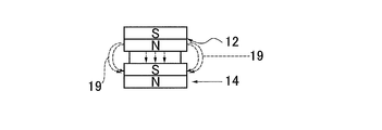
- the apparatus 10 includes a pair of magnets 12 and 14 that are permanent magnets, and a spacer 16. In the device 10, the spacer 16 is sandwiched between the magnets 12 and 14, and the device 10 has a long rotating body shape in one direction.
- the glass substrate for end face polishing is held by a holder (not shown).
- the apparatus 10 is arranged in the vicinity of the outer peripheral end face of the glass substrate held by the holder, and the mass 20 of the magnetic functional fluid (see FIGS. 10 and 11) and the outer peripheral end face of the glass substrate are brought into contact with each other.
- a holder (not shown) that holds the apparatus 10 and the glass substrate is mechanically connected to a drive motor (not shown). By driving the drive motor, as shown in FIG. 11, the apparatus 10 and the holder are rotated, and the outer peripheral side end face of the glass substrate and the lump 20 are relatively moved. Thereby, grinding
- FIG. 8 has a structure in which a spacer 16 is sandwiched between magnets 12 and 14, but may include an exterior member 18 (see FIG. 11) that covers this structure. Furthermore, the apparatus 10 can be penetrated through a circular hole provided at the center of the glass substrate, and the inner peripheral side end face of the glass substrate can be polished using the lump 20 provided on the outer periphery of the apparatus 10. Moreover, you may arrange
- the magnet 12 and the magnet 14 are close to each other and function as magnetism generating means to form a magnetic force line 19 as shown in FIG.
- the magnetic force lines 19 travel outward from the centers of the magnets 12 and 14 and travel in the thickness direction of the glass substrate.
- a magnetic slurry lump 20 as shown in FIG. In FIG. 10, the magnetic functional fluid mass 20 protrudes outward from the outer peripheral surface of the magnets 12 and 14, but the magnetic functional fluid mass 20 protrudes outward from the outer peripheral surface of the magnets 12 and 14. It does not have to protrude.
- the magnetic flux density in the magnetism generating means may be set to such an extent that the magnetic slurry lump 20 is formed.
- the end surface is efficiently polished, and the end surface has the above-mentioned surface shape.
- a permanent magnet is used as the magnetism generating means, but an electromagnet can also be used.
- the magnets 12 and 14 are fixed to an exterior member (not shown) without using the spacer 16, and the separation distance between the N pole end face of the magnet 12 and the S pole end face of the magnet 14 can be secured constant. it can.
- the magnetic functional fluid used for end face polishing includes, for example, a nonpolar oil containing 3 to 5 g / cm 3 of magnetic particles made of Fe, and a surfactant.
- a magnetorheological fluid is used.
- Nonpolar oil or polar oil has a viscosity of 100 to 1000 (mPa ⁇ sec) at room temperature (20 ° C.), for example.
- the average particle diameter d50 (diameter) of the magnetic particles is preferably 2 to 7 ⁇ m, for example.
- the lump 20 formed by the magnetic functional fluid includes abrasive grains in the lump 20 in the same manner as the magnetic particles when the magnetic functional fluid containing magnetic particles is formed as the lump 20 on the lines of magnetic force.
- the abrasive grains in the magnetic functional fluid are pushed out to a portion having a low magnetic force gradient due to the magnetic levitation effect, the abrasive grains are present in the vicinity of the end face of the glass substrate to be polished. And since it becomes a lump (hard lump) which has comparatively high elastic characteristics with a line of magnetic force, it can grind efficiently by pressing the end face of a glass substrate to lump 20. That is, the polishing rate can be increased and polishing can be performed efficiently.
- abrasive grains contained in the magnetic functional fluid known abrasive grains of glass substrates such as cerium oxide, colloidal silica, zirconia oxide, alumina abrasive grains, diamond abrasive grains, silica abrasive grains, and SiC abrasive grains may be used. it can.
- the particle size of the abrasive grains is, for example, 2 to 7 ⁇ m. By using the abrasive grains in this range, the end face polishing can be efficiently performed, and the inner peripheral side end face of the glass substrate can be satisfactorily polished.
- the abrasive grains are contained in the magnetic slurry, for example, 3 to 15 vol%.
- the magnetic functional fluid is, for example, a slurry in which abrasive grains are included in a magnetorheological fluid.
- the viscosity of the magnetic functional fluid is 1000 to 2000 (mPa ⁇ sec) at room temperature (20 ° C.) by adjusting the concentration of the magnetic viscous fluid. It is preferable in that it is performed frequently. If the viscosity is low (the concentration of the magnetorheological fluid is low), the lump 20 is difficult to form, and it is difficult to perform the relative movement while being pressed against the end face of the glass substrate 11 for polishing.
- the lump 20 has a shape recessed along the end shape of the glass substrate 11 during polishing, and is difficult to recover from the shape. Since the shape remains strong, it is difficult to form a uniform pressed state.
- the magnetic flux density in the magnetism generating means is preferably 0.3 to 2 [Tesla] from the viewpoint that the lump 20 is formed and the end face polishing is performed efficiently.
- the processing conditions include, for example, the viscosity of the magnetic functional fluid, the types of magnetic particles and abrasive grains, the particle size of the abrasive grains, the contents of the magnetomagnetic particles and abrasive grains, the magnetic flux density of the magnets 12 and 14, and the magnet 12 and 14 and at least the relative speed of the glass substrate G at the polishing position and the pressing force to the lump 20 of the glass substrate G.
- the polishing amount (removal allowance) by end face polishing is preferably 10 to 50 ⁇ m in depth from the surface (20 to 100 ⁇ m in terms of the diameter of the glass substrate). If it is less than 10 ⁇ m, there is a possibility that grinding scratches due to shape processing cannot be removed sufficiently. On the other hand, if it is larger than 50 ⁇ m, it takes too much processing time and there is a risk of deteriorating productivity. It is preferable that the depth from the surface be 20 ⁇ m (40 ⁇ m in terms of the diameter of the glass substrate) or more because it can be removed to the depth of damage (latent scratch) generated in the substrate by grinding. However, it should be noted that new damage due to the polishing process occurs at this time.
- (E) Grinding process grinding is performed on the main surface of the glass substrate using a double-sided grinding apparatus having a planetary gear mechanism. Specifically, the main surfaces on both sides of the glass substrate are ground while holding the outer peripheral side end face of the glass substrate in the holding hole provided in the holding member of the double-side grinding apparatus.
- the double-sided grinding apparatus has a pair of upper and lower surface plates (upper surface plate and lower surface plate), and a glass substrate is sandwiched between the upper surface plate and the lower surface plate. Then, either the upper surface plate or the lower surface plate, or both of them are moved, and both the main surfaces of the glass substrate are ground by moving the glass substrate and each surface plate relatively while supplying the coolant. can do.
- a grinding member in which fixed abrasive grains in which diamond is fixed with a resin is formed in a sheet shape can be mounted on a surface plate for grinding. Note that the processing order of the grinding process and the end face polishing process may be interchanged.
- the glass substrate is polished while applying a polishing slurry using a double-side polishing apparatus having the same configuration as the double-side grinding apparatus used for the above-described grinding process using fixed abrasive grains.
- a polishing slurry containing loose abrasive grains is used.
- the free abrasive grains used for the first polishing for example, abrasive grains such as cerium oxide or zirconia are used.
- the glass substrate is sandwiched between a pair of upper and lower surface plates.
- An annular flat polishing pad (for example, a resin polisher) is attached to the upper surface of the lower surface plate and the bottom surface of the upper surface plate as a whole. Then, by moving either the upper surface plate or the lower surface plate, or both, the glass substrate and each surface plate are relatively moved, thereby polishing both main surfaces of the glass substrate.
- the size of the abrasive grains is preferably in the range of 0.5 to 3 ⁇ m in terms of average particle diameter (D50).
- the glass substrate is subjected to second polishing.
- the second polishing treatment aims at mirror polishing of the main surface.
- a double-side polishing apparatus having the same configuration as the double-side polishing apparatus used for the first polishing is used. Specifically, the main surface on both sides of the glass substrate is polished while the outer peripheral side end surface of the glass substrate is held in the holding hole provided in the polishing carrier of the double-side polishing apparatus.
- the second polishing process is different from the first polishing process in that the type and particle size of the free abrasive grains are different and the hardness of the resin polisher is different.
- the hardness of the resin polisher is preferably smaller than that during the first polishing process.
- a polishing liquid containing colloidal silica as loose abrasive grains is supplied between the polishing pad of the double-side polishing apparatus and the main surface of the glass substrate, and the main surface of the glass substrate is polished.
- the size of the abrasive grains used for the second polishing is preferably in the range of 5 to 50 nm in terms of average particle diameter (d50).
- whether or not the chemical strengthening treatment is necessary may be appropriately selected in consideration of the glass composition and necessity.
- another polishing process may be added, and the polishing process of the two main surfaces may be performed by one polishing process. Moreover, you may change suitably the order of said each process.
- the present embodiment it is possible to suppress a decrease in the S / N ratio of the reproduction signal by suppressing the corrosion even under the flying condition in which the flying distance is reduced compared to the conventional case. That is, it is possible to adapt to quality requirements as a glass substrate for a magnetic disk mounted on a hard disk drive together with a DFH head (a magnetic head having a DFH function). In particular, it is suitable as a glass substrate for a magnetic disk that is mounted on a hard disk drive together with a DFH head that is equipped with an HDI sensor and can control the protruding amount of a recording / reproducing element based on a signal from the HDI sensor.
- the method for producing the glass substrate intermediate includes a process of polishing the end surface of the glass substrate containing an alkaline earth metal component as a glass composition to produce the glass substrate intermediate.
- the processing end surface after processing the glass substrate intermediate is a load factor curve of the roughness cross-sectional area obtained when measuring the surface roughness of the processing end surface after etching the processing end surface by 2.5 ⁇ m.
- the end surface of the glass substrate is polished so as to have a surface having a roughness percentage of 40% or more when the load factor of the roughness cross-sectional area is 50%.
- main surface grinding treatment for example, main surface grinding treatment, (f) first polishing treatment, or (g) chemical strengthening treatment is performed as necessary.
- first polishing treatment for example, first polishing treatment
- chemical strengthening treatment is performed as necessary.
- the glass substrate in a state after the end face polishing process and before at least (h) the second polishing (final polishing) process is referred to as a glass substrate intermediate. Therefore, after manufacturing the glass substrate intermediate, for example, when the glass substrate intermediate is transported to another place to produce a magnetic disk glass substrate, at least a polishing process (second polishing process) is performed on the main surface of the glass substrate intermediate. ), The final product glass substrate for magnetic disk can be obtained. In this case, before the second polishing process, it is preferable to perform a grinding process on the main surface, a first polishing process, or a chemical strengthening process as necessary
- the end surface of the disk-shaped glass plate was subjected to shape processing so as to have a chamfering width of 0.15 mm and a chamfering angle of 45 ° to obtain an inner peripheral side end surface and an outer peripheral side end surface, and then an end surface polishing process was performed.
- shape processing first, roughing was performed by grinding without tilting the grindstone using a general-purpose grindstone, and then finishing was performed by helical grinding with an inclination of 3 ° by changing the grindstone. Then, various end surface grinding
- the manufactured magnetic disk glass substrate is a magnetic disk glass substrate with a nominal 2.5 inch size having an outer diameter of about 65 mm, an inner diameter of about 20 mm, and a plate thickness of about 0.635 mm.
- the magnetic functional fluid used in the end surface polishing treatment is a magnetic slurry in which abrasive grains are included in a magnetorheological fluid containing magnetic particles, and has a viscosity of 1000 (mPa ⁇ sec) at room temperature (20 ° C.). did. Fe particles having an average particle diameter d50 of 2.0 ⁇ m were used as magnetic particles, and zirconia particles having an average particle diameter d50 of 0.5 ⁇ m were used as abrasive grains.
- the side wall surface and the chamfered surface of the glass substrate were polished by the method shown in FIG. 11 using a magnetic functional fluid having the same composition.
- the rotation axes of the glass substrate or the magnet are vibrated or oscillated in a direction toward or away from each other so that the force that the glass substrate G presses against the mass 20 of the magnetic functional fluid slightly vibrates or slightly swings. It was.
- the frequency and amplitude were appropriately selected and combined within a range of 1 to 50 Hz for vibration or oscillation and an amplitude (half the width of fluctuation) of 0.2 to 2 mm.
- the state of polishing of the side wall surface and the chamfered surface is slightly changed by this magnetic functional fluid, which affects the formation of latent cracks on the end surface of the glass substrate G.
- the side wall surface and the chamfered surface of the glass substrate are the same type used for the magnetic functional fluid, and abrasive grains having the same average particle diameter d50, that is, zirconia having an average particle diameter d50 of 0.5 ⁇ m. Polishing was performed using a polishing brush with a polishing slurry containing particles.
- Example 2 the side wall surface and the chamfered surface of the glass substrate were polished with a polishing slurry containing a polishing slurry of ceria particles having an average particle diameter d50 of 1.0 ⁇ m.
- the manufacturing conditions of Conventional Examples 1 and 2 are the same as those of Example 1 except for end face polishing.
- the polishing amount (removal allowance) by end face polishing was set to a depth of 20 ⁇ m from the surface (40 ⁇ m in terms of the diameter of the glass substrate) so that grinding flaws due to shape processing could be sufficiently removed in both magnetic functional fluid polishing and brush polishing.
- the end surface before the etching process of the glass substrate for magnetic disks obtained in Experimental Example 1 was a mirror surface on both the outer peripheral side wall surface and the chamfered surface including those described later.
- the side wall surface and the chamfered surface on the inner peripheral side were similarly mirror surfaces.
- the arithmetic average roughness Ra was 0.015 ⁇ m or less, and Rz was 0.15 ⁇ m or less.
- the arithmetic average roughness Ra was measured with an atomic force microscope with respect to the main plane of the glass substrate and the microwaviness ( ⁇ Wa) was measured with a scanning white interferometer, the arithmetic average roughness Ra was 0 on all the glass substrates.
- the swell ( ⁇ Wa) was 0.15 nm or less in all the glass substrates for magnetic recording media.
- the glass substrates for magnetic disks of Examples 1 to 8, Comparative Example, and Conventional Examples 1 and 2 were placed in an atmosphere of 80 ° C. and 85% humidity for 48 hours. After being allowed to stand, the presence or absence of corrosion was subjected to surface observation by SEM (scanning electron microscope) and component analysis by EDS (Energy Dispersive X-ray Spectrometry). Since the substance caused by the corrosion adhering to the end face of the glass substrate can be identified from its shape and components by the above observation and analysis, the adhesion area of the identified substance is evaluated by the surface observation by the SEM, and the occurrence of corrosion is further evaluated. The surface scratches were evaluated.
- Corrosion occurs when the side wall surface of the glass substrate is observed with 10 observations at an observation magnification of 5000 times using an SEM, and foreign matter (corrosion) containing alkaline earth metal elements of Mg, Ca, and Sr is observed in the visual field.
- the number of spots was counted and evaluated. The level was divided as follows according to the count. Levels 1 to 3 are acceptable and levels 4 and 5 are unacceptable. Level 1: 0 places where corrosion was observed Level 2: 1 place where corrosion was observed Level 3: 3 places where corrosion was observed 4: 4 places where corrosion was observed 5, 6 places Level 5: 7 or more places where corrosion was observed Table 1 shows the results.
- Example 2 The various types of glass substrates for magnetic disks (unused products) manufactured in Experimental Example 1 were annealed at 600 °, and then the same corrosion and surface scratches were evaluated as in Experimental Example 1.
- the surface shape of the end face having a roughness percentage of 40% or more when the load factor of the roughness cross-sectional area is 50% is provided as in Table 1 despite the annealing treatment.
- good corrosion suppression was observed.
- the evaluation of the scratches on the surface it was found that the generation of very thin scratches was suppressed under the condition that the roughness percentage when the load factor of the roughness cross-sectional area was 50% was 60% or less.
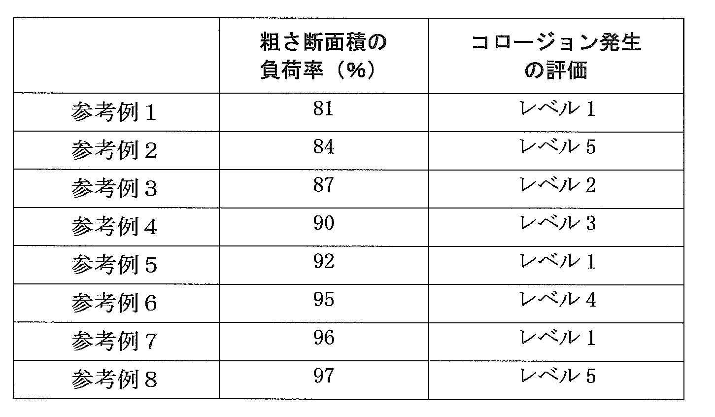
- Example 4 Based on the manufacturing conditions of Experimental Example 1, the surface shape of the end face before the etching process is adjusted by appropriately adjusting the processing conditions of the shape processing process and the end face polishing process using the magnetic functional fluid (Reference Examples 1 to 8). Eight types of glass substrates for magnetic disks with various modifications were produced. In addition, the adjustment of the processing conditions of the end surface polishing treatment is performed by adjusting the average particle diameter d50 and type of the abrasive grains contained in the magnetic functional fluid, and further, vibration or oscillation of the rotating shaft in the end surface polishing using the magnetic functional fluid. This was done by changing the conditions.
Landscapes
- Chemical & Material Sciences (AREA)
- Engineering & Computer Science (AREA)
- Ceramic Engineering (AREA)
- Inorganic Chemistry (AREA)
- Manufacturing & Machinery (AREA)
- Manufacturing Of Magnetic Record Carriers (AREA)
- Magnetic Record Carriers (AREA)
- Recording Or Reproducing By Magnetic Means (AREA)
- Glass Compositions (AREA)
- Surface Treatment Of Glass (AREA)
Abstract
Description
当該ガラス基板は、ダイヤモンド砥粒を固定した砥石で面取り加工を行った後、研磨ブラシを用いて端面研磨を行なって得られたものであり、ガラス基板の面取り面の表面を5μmエッチングした後に観察される直径または長径が10μm以上のピット欠陥が5個/mm2以下とするガラス基板である。
このため、浮上距離を1nm以下とする浮上条件では、今まで考慮する必要の無かった現象によって再生信号のSN比が低下したものと考えられる。
アルカリ土類金属成分をガラス組成として含む磁気ディスク用ガラス基板であって、
前記ガラス基板の端面は、鏡面であり、
前記端面は、前記端面を2.5μmエッチングした後の前記端面の表面粗さを測定したときに得られる粗さ断面積の負荷率曲線において、粗さ断面積の負荷率が50%であるときの粗さ百分率が40%以上である面を備える。
前記ガラス基板中間体の端面は、鏡面であり、
前記端面は、前記端面を2.5μmエッチングした後の前記端面の表面粗さを測定したときに得られる粗さ断面積の負荷率曲線において、粗さ断面積の負荷率が50%であるときの粗さ百分率が40%以上である面を備える。
本願発明者は、このコロージョンの発生を抑制するために、ガラス基板の端面の表面形状とコロージョンの発生を鋭意検討した結果、以下の技術を想到するに至った。
・粗さ断面積の負荷率、算術平均粗さRa、及び最大高さRzの値を求めるために行なうガラス基板の端面の表面形状の計測は、レーザ顕微鏡を用いて、50μm四方の評価領域にて以下の条件で行なわれる。
観察倍率:3000倍、
高さ方向(Z軸)の測定ピッチ:0.01μm、
カットオフ値λs:0.25μm、
カットオフ値λc:80μm。
なお、高さ方向の分解能は1nm以下であることが好ましい。また、本実施形態では観察倍率3000倍であるが、観察倍率は測定面の大きさに応じて、1000~3000倍程度の範囲で適宜選択される。
磁気ディスクは、円板形状の中心部分が同心円形状にくり抜かれたドーナッツ状を成し、リングの中心の周りに回転する。磁気ディスクは、ガラス基板と、少なくとも磁性層(磁性膜)と、を備える。なお、磁性層以外には、例えば、付着層、軟磁性層、非磁性下地層、垂直磁気記録層、保護層および潤滑層等が形成される。付着層には、例えばCr合金等が用いられる。付着層は、ガラス基板との接着層として機能する。軟磁性層には、例えばCoTaZr合金等が用いられる。非磁性下地層には、例えばグラニュラー非磁性層等が用いられる。垂直磁気記録層には、例えばグラニュラー磁性層等が用いられる。保護層には、水素カーボンからなる材料が用いられる。潤滑層には、例えばフッ素系樹脂等が用いられる。
本実施形態のガラス基板の組成を限定するものではないが、本実施形態のガラス基板は好ましくは、酸化物基準に換算し、質量%表示で、
SiO2 40~61%、
Al2O3 15~23.5%、
MgO 2~20%、
CaO 0.1~40%、を含有し、
[SiO2]+0.43×[Al2O3]+0.59×[CaO]-74.6≦0、かつ、
[SiO2]+0.21×[MgO]+1.16×[CaO]-83.0≦0
である無アルカリガラスの組成からなるアモルファスのアルミノシリケートガラスである。上記[ ]は、[ ]内のガラス成分の含有率(質量%)である。以下、上記をガラス組成1とも呼ぶ。
また、その他の好ましいガラス組成として下記組成も挙げられる。すなわち、酸化物基準に換算し、質量%表示で、
SiO2 64~72%、
Al2O3 17~22%、
MgO 1~8%、
CaO 4~15.5%、を含有し、0.20≦[MgO]/([MgO]+[CaO])≦0.41
であるガラスの組成からなるアモルファスのアルミノシリケートガラスである。
なお、磁性膜を形成する時の加熱処理に対応するために、ガラス転移点(Tg)が600℃以上となるようにガラス組成を調整することが好ましい。ガラス転移点は、より好ましくは700℃以上、さらに好ましくは750℃以上である。特に、ガラス転移点を700℃以上とすると、前述の500~700℃の全温度領域の熱処理にも耐えうるため、ガラス転移点を700℃以上とすることが好ましい。このようなガラス基板は、エネルギーアシスト磁気記録方式用の磁気ディスク向けに用いるガラス基板として好適である。
図1は、本実施形態の磁気ディスク用ガラス基板の外観形状を示す図である。図2は、磁気ディスク用ガラス基板の外周側端面の拡大断面図である。
図1に示すように、本実施形態における磁気ディスク用ガラス基板は、内孔2が形成された、ドーナツ型の薄板のガラス基板である。ガラス基板のサイズ(直径)は問わない。ガラス基板は、例えば公称1.8~3.5インチサイズの基板に使用することができる。板厚についても特に制限はなく、例えば0.3~3mmとすることができる。
本実施形態のガラス基板は、図2に示すように、一対の主表面1pと、一対の主表面1pに対して垂直に延びるガラス基板の側壁面1tと、側壁面1tと主表面1pの間に設けられ、側壁面1tから側壁面1tに対して傾斜して延び、主表面1pに接続する面取り面1cとを有する。図示しないが、ガラス基板の内周側端面についても同様に、側壁面と面取り面が形成されている。なお、面取り面は、断面視において一部又は全部が円弧状に形成されていてもよい。
(要件1)ガラス基板の端面は鏡面であること、
(要件2)ガラス基板の端面を2.5μm、ウェットエッチングした後の端面の表面粗さを測定したときに得られる粗さ断面積の負荷率曲線において、粗さ断面積の負荷率が50%であるときの粗さ百分率が40%以上である、ガラス基板の端面は備えること。
より好ましくは、算術平均粗さRaは0.015μm以下であり、かつ、上記最大高さRzは0.15μm以下であることが好ましい。
「粗さ断面積の負荷率曲線」とは、対象となる表面近傍領域について、縦軸を粗さ百分率の軸とし、横軸を粗さ断面積の負荷率の軸としたときの、両者の関係を表した曲線である。
図5(a)に示すように、略一定のレベルの表面から凸部が間隔をあけて突出した波形cの場合、負荷率曲線Cは、粗さ百分率が0%から100%に進む(図中の縦軸下方向に進む)とき、負荷率は穏やかに上昇(図中の横軸右方向に進む)する曲線である。これに対して、図5(d)に示すように、略一定のレベルの表面から間隔をあけてクラック等の凹部が内部に進展した波形fの場合、負荷率曲線Fは、粗さ百分率が0%から100%に進む(図中の縦軸下方向に進む)とき、負荷率は急激に上昇する(図中の横軸右方向に進む)曲線である。図5(b)に示すように、凸部と凹部が略同じ比率で現れる一次元波形dの場合、負荷率曲線Dは、粗さ百分率が0%から100%に進む(図中の縦軸下方向に進む)とき、負荷率の上昇(図中の横軸右方向)の勾配が略一定の曲線であり、その勾配は、負荷率曲線Cの勾配と負荷率曲線Fの勾配との中間である。したがって、負荷率曲線から、表面形状がどのような形状であるかを把握することができる。
すなわち、要件2では、端面をウェットエッチングしても、顕在する潜在クラックが少ないことを意味する。したがって、要件1及び要件2を満足するガラス基板では、端面に微粒子が付着することは少なく、また、潜在クラックが少ないので、磁気ディスク製作時の成膜処理時の熱衝撃等により潜在クラックが広がって潜在クラックが顕在化しても顕在化したクラックは少ない。したがって、ガラス基板においてコロージョンの発生は抑制される。すなわち、本実施形態のガラス基板は、浮上距離を1nm以下とする記録素子あるいは再生素子の浮上条件において、記録再生の支障は少なく、信号のSN比の低下を抑制することができる。
ガラス基板がアルカリ土類金属成分を含む場合、アルカリ土類金属成分がガラス基板の表面に溶出し易い。このようなアルカリ土類金属成分を含むアルカリ土類含有ガラスからなるガラス基板であっても、本実施形態のガラス基板は潜在クラックが少ないので、コロージョンの発生を抑制することができる。
通常、磁性膜等の成膜工程において、側壁面1tは、爪状の保持治具と接触する一方、面取り面1cは、保持治具と接触しないため、面取り面1cと比べてダメージを受け易い。このため、特に、側壁面1tは、要件2を満足する表面形状を備えることが好ましい。なお、側壁面1tは、主表面の研削・研磨工程においてキャリア等との接触によるダメージを受ける場合もある。
さらに、ガラス基板の側壁面1t及び面取り面1cが、要件2を満足する表面形状を備えることよりが好ましい。これにより、ガラス基板の側壁面1t及び面取り面1cにおいてコロージョンの発生は抑制される。通常、面取り面1cは、磁性膜等の成膜工程や主表面の研削・研磨工程において、爪状の保持治具やキャリア等と接触しないため、側壁面1tと比べてダメージを受けにくいが、側壁面1tよりも主表面に近いため、コロージョンが発生した場合には主表面に移動し易い。したがって、側壁面1t及び面取り面1cの両方で要件1,2を満足させることで、主表面におけるコロージョンの発生をよりよく抑制することが可能となる。
なお、側壁面1tと面取り面1cの接続部分の曲率半径Rは、以下のように求めることができる。
なお、上記研削工程を2回に分け、1回目の研削を、上述したようにガラス基板Gの回転軸を角度α(α>0)だけ傾けた状態で行い、2回目の研削を、別の砥石を使用してガラス基板Gの回転軸を-αの角度だけ傾けた状態で行い、2回目の研削の取代を1回目の研削の取代より少なくなるように調整してもよい。なお、形状加工処理では、ヘリカル研削の前に、総型砥石による研削を行なうことがより好ましい。
次に、本実施形態の磁気ディスク用ガラス基板の製造方法を説明する。先ず、一対の主表面を有する板状の磁気ディスク用ガラス基板の素材となるガラスブランクをプレス成形により作製する(プレス成形処理)。なお、本実施形態ではガラスブランクをプレス成形で作製するが、周知のフロート法、リドロー法、あるいはフュージョン法でガラス板を形成し、ガラス板から上記ガラスブランクと同じ形状のガラスブランクを切り出してもよい。
次に、作製されたガラスブランクの中心部分に円形状の内孔を形成しリング形状(円環状)のガラス基板とする(円孔形成処理)。次に、内孔を形成したガラス基板の内周端部及び外周端部に対して面取り面を形成する形状加工を行う(形状加工処理)。これにより面取り面と側壁面とが端面に形成されたガラス基板が得られる。次に、形状加工されたガラス基板に対して端面研磨を行う(端面研磨処理)。端面研磨の行われたガラス基板に、固定砥粒による研削を行う(研削処理)。次に、ガラス基板の主表面に第1研磨を行う(第1研磨処理)。次に、必要に応じてガラス基板に対して化学強化を行う(化学強化処理)。次に、ガラス基板に対して第2研磨を行う(第2研磨処理)。その後、第2研磨処理後のガラス基板に対して超音波洗浄を行う(超音波洗浄処理)。以上の処理を経て、磁気ディスク用ガラス基板が得られる。以下、各処理について、詳細に説明する。
なお、本実施形態の、要件1,2を満足する磁気ディスク用ガラス基板は、磁気ディスク用ガラス基板の製造方法で製造された上記第2研磨(最終研磨)処理後の、最終製品である磁気ディスク用ガラス基板の他に、上記端面研磨処理後、第2研磨(最終研磨)処理前の、最終製品である磁気ディスク用ガラス基板の素板となるガラス基板中間体(以降、単に、ガラス基板中間体という)を含む。ガラス基板中間体は、端面研磨処理が行われたガラス基板であり、例えば、上記研削処理が行われる前のものや、上記研削処理が行われたが上記第1研磨処理が行われる前のもの、あるいは、上記研削処理及び上記第1研磨処理が行われたが、上記第2研磨処理前のものを含む。
熔融ガラス流の先端部を切断器により切断し、切断された熔融ガラス塊を一対の金型のプレス成形面の間に挟みこみ、プレスして円板形状のガラスブランクを成形する。所定時間プレスを行った後、金型を開いてガラスブランクが取り出される。
ガラスブランクに対してドリル等を用いて円形状の内孔を形成することにより円形状の孔があいたディスク状のガラス基板を得ることもできる。
形状加工処理では、円孔形成処理後のガラス基板の端面に対する面取り加工を行う。面取り加工は、研削砥石等を用いて行なわれる。面取り加工により、ガラス基板の端面に、ガラス基板の主表面に対して垂直に延びる基板の側壁面と、この側壁面と主表面の間に設けられ、側壁面に対して傾斜して延びる面取り面とを有する端面が形成される。
形状加工処理は、上述したヘリカル研削により、側壁面及び面取り面を形成してもよい。さらに、ヘリカル研削の前に、総型砥石による研削を行なってもよい。
端面研磨処理では、ガラス基板の外周側端面及び内周側端面に対して、以下のような磁気機能性流体を用いた端面研磨処理により鏡面仕上げを行う。磁気機能性流体には、磁性粒子の他に研磨砥粒が含まれる。これにより、要件1及び要件2を満足するガラス基板を得ることができる。すなわち、ガラス基板の端面を2.5μm、ウェットエッチングした後の端面の表面粗さを測定したときに得られる粗さ断面積の負荷率曲線において、粗さ断面積の負荷率が50%であるときの粗さ百分率が40%以上となる表面形状をガラス基板の端面が備えるように、端面の研磨が行われる。特に、ガラス基板の外周側端面に対して、磁気機能性流体を用いた端面研磨処理を行うことがコロージョンを抑制する点から好ましい。外周側端面は、内周側端面より面積が大きく、また、例えば磁気ディスクとして組み込まれるHDD(ハードディスクドライブ装置)内部において露出しているため、外周側端面でコロージョンが発生したときにこのコロージョンが磁気ヘッドに与える影響が大きくなり易い。
端面研磨を行う装置10は、磁気を発生させる手段と、磁性粒子と研磨砥粒を含む磁気機能性流体とを用いてガラス基板の端面の研磨を行う。端面研磨を行う装置10の概要を説明すると、図8に示すように、装置10は、永久磁石である一対の磁石12,14と、スペーサ16と、を含む。装置10では、磁石12,14の間にスペーサ16が挟まれており、装置10は、一方向に長い回転体形状を成している。端面研磨を行うガラス基板は、図示されない保持具によって把持されている。保持具に把持されたガラス基板の外周側端面の近傍に装置10を配置し、磁気機能性流体の塊20(図10,図11参照)とガラス基板の外周側端面とを接触させる。装置10及びガラス基板を保持する図示されない保持具は、図示されない駆動モータと機械的に接続されている。駆動モータの駆動により、図11に示すように、装置10と保持具が回転してガラス基板の外周側端面と塊20とが相対的に移動する。これにより、ガラス基板の外周側端面の研磨が行われる。装置10と保持具を、例えば500~2000rpmで相対的に回転させることにより、ガラス基板の外周側端面を研磨することができる。なお、装置10の回転をさせずに、ガラス基板のみを回転させることによって、ガラス基板の外周側端面と塊20とを相対的に移動させてもよい。図8に示す装置10は、磁石12,14の間にスペーサ16を挟んだ構造であるが、この構造を覆う外装部材18(図11参照)を備えてもよい。
さらに、装置10を、ガラス基板の中心に設けられた円形状の孔に貫通させて、装置10の外周に設けられた塊20を用いてガラス基板の内周側端面を研磨することもできる。また、内周側端面と外周側端面を同時に研磨するように、一対の磁石とスペーサを備えた装置を2つ配置してもよい。
磁気発生手段における磁束密度は、磁性スラリの塊20を形成させる程度に設定すればよいが、端面研磨を効率よく行い、端面が上記表面形状を備える点で、0.3~2[テスラ]であることが好ましい。
なお、図8~図11に示す例では、磁気発生手段として永久磁石を用いたが、電磁石を用いることもできる。また、スペーサ16を用いず、図示されない外装部材に磁石12,14が固定されて、磁石12のN極の端面と磁石14のS極の端面との間の離間距離を一定に確保することもできる。
磁気機能性流体により形成される塊20は、磁性粒子を含む磁気機能性流体が磁力線上に塊20として形成されるとき、磁性粒子と同様に研磨砥粒も塊20に含まれる。磁気機能性流体中の研磨砥粒は、磁気浮揚効果により磁力勾配の低い部分に押し出されるため、ガラス基板の研磨しようとする端面近傍に偏って存在する。しかも、磁力線により比較的高い弾性特性を有する塊(硬い塊)となるので、ガラス基板の端面を塊20に押圧することにより効率よく研磨することができる。すなわち、研磨レートを高くすることができ、効率よく研磨をすることができる。
上記端面研磨を行う際、処理条件を適宜設定することにより、ガラス基板の側壁面及び/又は面取り面は、要件1及び要件2を満足することができる。処理条件には、例えば、磁気機能性流体の粘度、磁性粒子及び研磨砥粒の種類、研磨砥粒の粒子サイズ、磁磁性粒子及び研磨砥粒の含有量、磁石12,14の磁束密度、磁石12,14とガラス基板Gとの研磨位置における相対的速度、ガラス基板Gの塊20への押し付け力を少なくとも含む。
なお、上述のヘリカル研削と磁気機能性流体を用いた研磨とを用いることが、ガラス基板Gの端面が要件1,2を満足する点から、好ましい。
また、端面研磨による研磨量(取代)は、表面からの深さが10~50μm(ガラス基板の直径換算で20~100μm)とすることが好ましい。10μm未満の場合、形状加工による研削傷を十分に除去できないおそれがある。また50μmより大きくすると、加工時間がかかりすぎて生産性の悪化を招く恐れがある。なお、表面からの深さを20μm(ガラス基板の直径換算で40μm)以上とすると、研削加工により基板内部に生じたダメージ(潜傷)の深さまで除去することができるので好ましい。ただし、このとき、研磨処理によるダメージが新たに発生することに注意が必要である。
研削処理では、遊星歯車機構を備えた両面研削装置を用いて、ガラス基板の主表面に対して研削加工を行う。具体的には、ガラス基板の外周側端面を、両面研削装置の保持部材に設けられた保持孔内に保持しながらガラス基板の両側の主表面の研削を行う。両面研削装置は、上下一対の定盤(上定盤および下定盤)を有しており、上定盤および下定盤の間にガラス基板が狭持される。そして、上定盤または下定盤のいずれか一方、または、双方を移動操作させ、クーラントを供給しながらガラス基板と各定盤とを相対的に移動させることにより、ガラス基板の両主表面を研削することができる。例えば、ダイヤモンドを樹脂で固定した固定砥粒をシート状に形成した研削部材を定盤に装着して研削処理をすることができる。なお、研削処理と上記端面研磨処理は、処理の順番を入れ替えてもよい。
次に、研削のガラス基板の主表面に第1研磨が施される。具体的には、ガラス基板の外周側端面を、両面研磨装置の研磨用キャリアに設けられた保持孔内に保持しながらガラス基板の両側の主表面の研磨が行われる。第1研磨は、研削処理後の主表面に残留したキズや歪みの除去、あるいは微小な表面凹凸(マイクロウェービネス、粗さ)の調整を目的とする。
ガラス基板を化学強化する場合、化学強化液として、例えば硝酸カリウムと硫酸ナトリウムの混合熔融液等を用い、ガラス基板を化学強化液中に浸漬する。これにより、イオン交換によってガラス基板の表面に圧縮応力層を形成することができる。
次に、ガラス基板に第2研磨が施される。第2研磨処理は、主表面の鏡面研磨を目的とする。第2研磨においても、第1研磨に用いる両面研磨装置と同様の構成を有する両面研磨装置が用いられる。具体的には、ガラス基板の外周側端面を、両面研磨装置の研磨用キャリアに設けられた保持孔内に保持させながら、ガラス基板の両側の主表面の研磨が行われる。第2研磨処理が第1研磨処理と異なる点は、遊離砥粒の種類及び粒子サイズが異なることと、樹脂ポリッシャの硬度が異なることである。樹脂ポリッシャの硬度は第一研磨処理時よりも小さいことが好ましい。例えばコロイダルシリカを遊離砥粒として含む研磨液が両面研磨装置の研磨パッドとガラス基板の主表面との間に供給され、ガラス基板の主表面が研磨される。第2研磨に用いる研磨砥粒の大きさは、平均粒径(d50)で5~50nmの範囲内であることが好ましい。
本実施形態では、化学強化処理の要否については、ガラス組成や必要性を考慮して適宜選択すればよい。第1研磨処理及び第2研磨処理の他にさらに別の研磨処理を加えてもよく、2つの主表面の研磨処理を1つの研磨処理で済ませてもよい。また、上記各処理の順番は、適宜変更してもよい。
この後、例えば、(e)主表面研削処理、必要に応じて(f)第1研磨処理、あるいは(g)化学強化処理が行われる。
このように、端面研磨処理後であって、少なくとも(h)第2研磨(最終研磨)処理を行う前の状態のガラス基板をガラス基板中間体と呼ぶ。
したがって、ガラス基板中間体を作製した後、例えばガラス基板中間体を別の場所に搬送して磁気ディスク用ガラス基板を製造する場合、ガラス基板中間体の主表面に少なくとも研磨処理(第2研磨処理)を行うことで、最終製品である磁気ディスク用ガラス基板を得ることができる。この場合、第2研磨処理の前に、必要に応じて、主表面の研削処理、第1研磨処理、あるいは化学強化処理を行うとよい。
本実施形態のガラス基板の効果を調べるために、形状加工処理をしたガラス組成1のガラス基板の側壁面及び面取り面に種々の端面研磨処理を施した。なお、アルカリ金属成分は含まず、Tgが700℃以上となるようにガラス組成を調整した。
具体的には、プレス法により得た円盤状のガラスブランクに円孔形成処理を施し、中央部に円孔を有する円盤状ガラス基板を得た。使用したガラス組成は上述のガラス組成1である。この円盤状ガラス板の上下主表面の研削処理を一対の研削定盤を備えた両面研削装置を用いて行い、板厚0.7mmとした。この後、円盤状ガラス板の端面を、面取り幅0.15mm、面取り角度45°となるように形状加工処理を行って内周側端面と外周側端面を得た後、端面研磨処理を実施した。形状加工処理では、総型砥石を用いて、最初に砥石を傾けない研削処理による粗加工を行ない、次に砥石を変えて傾き3°のヘリカル研削処理による仕上げ加工を行った。
その後、形状加工処理をしたガラス基板の側壁面及び面取り面に種々の端面研磨処理(後述)を施した。なお、端面研磨処理以外の処理については、上記の実施形態に沿った内容で行い、1つの条件あたり200枚ずつの磁気ディスク用ガラス基板を製造した。ただし、化学強化処理は行わなかった。
端面研磨処理以降の処理として、具体的には、
・固定砥粒による主表面の研削処理、
・第1研磨(酸化セリウム(d50:1μm)と硬質のポリウレタン研磨パッドを用いて行なった)、
・第2研磨(コロイダルシリカ(d50:30nm)と軟質のポリウレタン研磨パッドを用いて行なった)、
・洗浄処理、
を順次行い、磁気ディスク用ガラス基板を製造した。製造した磁気ディスク用ガラス基板は、外径約65mm、内径約20mm、板厚約0.635mmの公称2.5インチサイズの磁気ディスク用ガラス基板である。
なお、端面研磨処理において使用した磁気機能性流体は、磁性粒子を含む磁気粘性流体に研磨砥粒を含ませた磁性スラリであり、室温(20℃)において1000(mPa・秒)の粘度を有した。
磁性粒子として平均粒径d50が2.0μmのFe粒子を用い、研磨砥粒として平均粒径d50が0.5μmのジルコニア粒子を用いた。
この研磨では、ガラス基板Gが磁気機能性流体の塊20に押し付ける力が微小振動又は微小遥動するように、ガラス基板又は磁石の回転軸をお互いに向かう方向あるいは離れる方向に振動又は揺動させた。このとき、振動又は揺動の周波数は1~50Hz、振幅(変動の幅の半分)が0.2~2mmの範囲内で適宜周波数及び振幅を選択し、組み合わせた。こうすることで、ガラス基板と塊20が接触してガラス基板が研磨する加工点において振動又は揺動を生じさせることが可能となる。なお、ガラス基板と磁石の両方の回転軸を振動または揺動してもよい。各条件は、以下の傾向を基に適宜設定した。すなわち、振動又は揺動の周波数を高くすると、粗さ断面積の負荷率50%における粗さ百分率が大きくなる傾向にある。また、振幅を大きくすると、粗さ百分率が大きくなる傾向にある。振幅又は揺動で研磨面の品質が改善するのは、円形に形成された磁場の強さが円周方向に沿って微視的に見たときに必ずしも均一ではないためと推察される。
この磁気機能性流体により側壁面及び面取り面の研磨の状態がわずかに変化し、これがガラス基板Gの端面の潜在クラックの形成に影響を与える。
一方、従来例1として、ガラス基板の側壁面と面取り面を、上記磁気機能性流体に用いた同じ種類、同じ平均粒径d50の研磨砥粒、すなわち、平均粒径d50が0.5μmのジルコニア粒子を含んだ研磨スラリで研磨ブラシを用いて研磨した。
さらに、従来例2として、ガラス基板の側壁面と面取り面を、平均粒径d50が1.0μmのセリア粒子の研磨砥粒を含んだ研磨スラリで研磨ブラシを用いて研磨した。なお、従来例1,2の製造条件は、端面研磨以外は実施例1と同じである。
端面研磨による研磨量(取代)は、磁気機能性流体研磨とブラシ研磨ともに、形状加工による研削傷を十分に除去できるように表面からの深さ20μm(ガラス基板の直径換算で40μm)とした。
この端研磨処理によって得られた実施例1~8、比較例、及び従来例1,2のガラス基板の端面(側壁面及び面取り面)に、フッ酸を含んだエッチング液に浸漬して端面の表面を2.5μmエッチングした後、ガラス基板の端面(側壁面)の表面形状を計測した。さらに、この計測結果から、粗さ断面積の負荷率曲線の、粗さ断面積の負荷率が50%における粗さ百分率の値を求めた。結果を表1に示す。
ところで、本実験例1において得られた磁気ディスク用ガラス基板のエッチング処理前の端面は、後述するものも含めて、外周側の側壁面及び面取り面ともに鏡面であった。また、内周側の側壁面及び面取り面についても同様に鏡面であった。また、端面の粗さについてはいずれも、算術平均粗さRaは0.015μm以下、Rzは0.15μm以下であった。また、ガラス基板の主平面について算術平均粗さRaを原子間力顕微鏡により測定し、微小うねり(μWa)を走査型白色干渉計により測定したところ、算術平均粗さRaは全てのガラス基板において0.15nm以下であり、微小うねり(μWa)は、全ての磁気記録媒体用ガラス基板において0.15nm以下であった。
コロージョンの発生は、ガラス基板の側壁面を、SEMを用いて5000倍の観察倍率で10視野観察し、Mg、Ca、Srのアルカリ土類金属元素を含む異物(コロージョン)が視野中に観測された箇所をカウントして評価した。カウントに応じて下記のとおりレベル分けした。レベル1~3は合格、レベル4,5は不合格である。
レベル1:コロージョンが観測された箇所が0箇所
レベル2:コロージョンが観測された箇所が1、2箇所
レベル3:コロージョンが観測された箇所が3、4箇所
レベル4:コロージョンが観測された箇所が5、6箇所
レベル5:コロージョンが観測された箇所が7箇所以上
下記表1にその結果を示す。

実験例1で製造した各種の磁気ディスク用ガラス基板(未使用品)に対して、600°でアニール処理した後、実験例1と同じコロージョンと表面キズの評価を実施した。その結果、コロージョン評価においては、アニール処理したにもかかわらず、表1と同様に、粗さ断面積の負荷率が50%のときの粗さ百分率が40%以上である端面の表面形状を備える実施例において良好なコロージョンの抑制が見られた。また、表面の傷の評価においても、粗さ断面積の負荷率が50%のときの粗さ百分率が60%以下の条件においてごく薄い傷の発生が抑制されることが見られた。
実験例1で製造した各種の磁気ディスク用ガラス基板(未使用品)に対して、上述の磁性膜のほかに、付着層、軟磁性層、非磁性下地層、垂直磁気記録層、保護層および潤滑層等を設けるように成膜処理を施し、磁気ディスクを製造した。なお、磁性膜の形成後に600°でアニール処理も実施した。得られた磁気ディスクを用いて、DFHヘッドの記録再生素子部の浮上距離を1nmとした条件で長期信頼性テスト(信号の記録・再生の連続実行テスト)を行なったところ、実施例の端面研磨処理を行った磁気ディスク用ガラス基板を用いた磁気ディスクにおいては再生信号のSN比が低下する現象は確認されなかった。
実験例1の製造条件を元に、形状加工処理及び磁気機能性流体を用いた端面研磨処理の処理条件を適宜調整する(参考例1~8)ことにより、エッチング処理前の端面の表面形状を様々に変更した磁気ディスク用ガラス基板を8種類製造した。なお、端面研磨処理の処理条件の調整は、磁気機能性流体に含まれる研磨砥粒の平均粒径d50及び種類、さらには、磁気機能性流体を用いた端面研磨における回転軸の振動または揺動の条件等を変更することにより行った。
得られた8種類の磁気ディスク用ガラス基板(エッチング未処理)のそれぞれについて、
・レーザ顕微鏡を用いて前述の測定条件で側壁面の表面形状を計測し、粗さ百分率が60%における粗さ断面積の負荷率を求めること、
・各種類の複数枚のガラス基板のうち残りの基板(未使用)を用いて実験例1と同じコロージョンの発生の評価を実施すること、
の2点を実行した。結果を下記表2に示す。表2から明らかなように、エッチング処理前のガラス基板の側壁面における粗さ百分率が60%における粗さ断面積の負荷率と、コロージョンの発生との間には、何ら相関がないことがわかる。
1p 主表面
1t 側壁面
2 内孔
10 装置
12,14 磁石
16 スペーサ
20 塊
40 研削砥石
50 溝
50a 側壁部
50b 面取り部
Claims (14)
- アルカリ土類金属成分をガラス組成として含む磁気ディスク用ガラス基板であって、
前記ガラス基板の端面は、鏡面であり、
前記端面は、前記端面を2.5μmエッチングした後の前記端面の表面粗さを測定したときに得られる粗さ断面積の負荷率曲線において、粗さ断面積の負荷率が50%であるときの粗さ百分率が40%以上である面を備える、
ことを特徴とする磁気ディスク用ガラス基板。 - 前記粗さ百分率は50%以上である、請求項1に記載の磁気ディスク用ガラス基板。
- 前記粗さ百分率は60%以下である、請求項1又は2に記載の磁気ディスク用ガラス基板。
- 前記鏡面における算術平均表面粗さは0.015μm以下である、請求項1~3のいずれか1項に記載の磁気ディスク用ガラス基板。
- 前記磁気ディスク用ガラス基板を構成するガラスのガラス転移点は700℃以上である、請求項1~4のいずれか1項に記載の磁気ディスク用ガラス基板。
- 前記磁気ディスク用ガラス基板を構成するガラスは無アルカリガラスである、請求項1~5のいずれか1項に記載の磁気ディスク用ガラス基板。
- 前記ガラス基板は、DFH(Dynamic Flying Height)機能を備えた磁気ヘッドとともにハードディスクドライブに搭載される磁気ディスク用のガラス基板である、請求項1~6のいずれか1項に記載の磁気ディスク用ガラス基板。
- 前記ガラス基板は、エネルギーアシスト磁気記録方式用の磁気ディスクに用いられるガラス基板である、請求項1~7のいずれか1項に記載の磁気ディスク用ガラス基板。
- 請求項1~8のいずれか1項に記載の磁気ディスク用ガラス基板の表面に少なくとも磁性膜を有する、磁気ディスク。
- アルカリ土類金属成分をガラス組成として含み、磁気ディスク用ガラス基板の素板となるガラス基板中間体であって、
前記ガラス基板中間体の端面は、鏡面であり、
前記端面は、前記端面を2.5μmエッチングした後の前記端面の表面粗さを測定したときに得られる粗さ断面積の負荷率曲線において、粗さ断面積の負荷率が50%であるときの粗さ百分率が40%以上である面を備える、
ことを特徴とするガラス基板中間体。 - 前記粗さ百分率は50%以上である、請求項10に記載のガラス基板中間体。
- 前記粗さ百分率は60%以下である、請求項10又は11に記載のガラス基板中間体。
- 前記ガラス基板中間体を構成するガラスは無アルカリガラスである、請求項10~12のいずれか1項に記載のガラス基板中間体。
- 請求項10~13のいずれか1項に記載のガラス基板中間体の主表面に少なくとも研磨処理を行うことを特徴とする、磁気ディスク用ガラス基板の製造方法。
Priority Applications (6)
| Application Number | Priority Date | Filing Date | Title |
|---|---|---|---|
| CN201680029894.4A CN107615381B (zh) | 2015-09-30 | 2016-09-30 | 磁盘用玻璃基板、磁盘、玻璃基板中间体和磁盘用玻璃基板的制造方法 |
| JP2017502273A JP6106813B1 (ja) | 2015-09-30 | 2016-09-30 | 磁気ディスク用ガラス基板、磁気ディスク、ガラス基板中間体、及び磁気ディスク用ガラス基板の製造方法 |
| SG11201709624VA SG11201709624VA (en) | 2015-09-30 | 2016-09-30 | Magnetic-disk glass substrate, magnetic-disk glass substrate intermediate, and method for manufacturing magnetic-disk glass substrate |
| US15/579,033 US10720180B2 (en) | 2015-09-30 | 2016-09-30 | Magnetic-disk glass substrate, magnetic-disk glass substrate intermediate, and method for manufacturing magnetic-disk glass substrate |
| US16/884,931 US11211090B2 (en) | 2015-09-30 | 2020-05-27 | Magnetic-disk glass substrate, magnetic-disk glass substrate intermediate, and method for manufacturing magnetic-disk glass substrate |
| US17/548,008 US11710505B2 (en) | 2015-09-30 | 2021-12-10 | Magnetic-disk glass substrate, magnetic-disk glass substrate intermediate, and method for manufacturing magnetic-disk glass substrate |
Applications Claiming Priority (2)
| Application Number | Priority Date | Filing Date | Title |
|---|---|---|---|
| JP2015-195128 | 2015-09-30 | ||
| JP2015195128 | 2015-09-30 |
Related Child Applications (2)
| Application Number | Title | Priority Date | Filing Date |
|---|---|---|---|
| US15/579,033 A-371-Of-International US10720180B2 (en) | 2015-09-30 | 2016-09-30 | Magnetic-disk glass substrate, magnetic-disk glass substrate intermediate, and method for manufacturing magnetic-disk glass substrate |
| US16/884,931 Continuation US11211090B2 (en) | 2015-09-30 | 2020-05-27 | Magnetic-disk glass substrate, magnetic-disk glass substrate intermediate, and method for manufacturing magnetic-disk glass substrate |
Publications (1)
| Publication Number | Publication Date |
|---|---|
| WO2017057686A1 true WO2017057686A1 (ja) | 2017-04-06 |
Family
ID=58423694
Family Applications (1)
| Application Number | Title | Priority Date | Filing Date |
|---|---|---|---|
| PCT/JP2016/079037 Ceased WO2017057686A1 (ja) | 2015-09-30 | 2016-09-30 | 磁気ディスク用ガラス基板、磁気ディスク、ガラス基板中間体、及び磁気ディスク用ガラス基板の製造方法 |
Country Status (6)
| Country | Link |
|---|---|
| US (3) | US10720180B2 (ja) |
| JP (2) | JP6106813B1 (ja) |
| CN (2) | CN107615381B (ja) |
| MY (1) | MY168096A (ja) |
| SG (1) | SG11201709624VA (ja) |
| WO (1) | WO2017057686A1 (ja) |
Families Citing this family (7)
| Publication number | Priority date | Publication date | Assignee | Title |
|---|---|---|---|---|
| SG11201501455YA (en) * | 2012-09-28 | 2015-05-28 | Hoya Corp | Magnetic-disk glass substrate, magnetic disk and method for manufacturing magnetic-disk glass substrate |
| WO2017057686A1 (ja) * | 2015-09-30 | 2017-04-06 | Hoya株式会社 | 磁気ディスク用ガラス基板、磁気ディスク、ガラス基板中間体、及び磁気ディスク用ガラス基板の製造方法 |
| JP6695318B2 (ja) * | 2017-12-27 | 2020-05-20 | Hoya株式会社 | 円盤状ガラス基板の製造方法、薄板ガラス基板の製造方法、導光板の製造方法及び円盤状ガラス基板 |
| JP7533100B2 (ja) * | 2020-10-07 | 2024-08-14 | 住友金属鉱山株式会社 | ウェハーの汚染検知方法 |
| US12266389B2 (en) * | 2021-02-24 | 2025-04-01 | Hoya Corporation | Magnetic disk substrate, magnetic disk, annular-shaped substrate, and method for manufacturing magnetic disk substrate |
| US11270724B1 (en) | 2021-03-04 | 2022-03-08 | Western Digital Technologies, Inc. | Glass substrates for heat assisted magnetic recording (HAMR) and methods and apparatus for use with the glass substrates |
| JP7732498B2 (ja) * | 2021-03-30 | 2025-09-02 | ソニーグループ株式会社 | 磁気記録媒体 |
Citations (6)
| Publication number | Priority date | Publication date | Assignee | Title |
|---|---|---|---|---|
| JPH07244947A (ja) * | 1994-03-08 | 1995-09-19 | Hitachi Ltd | 磁気ディスク装置、磁気ディスクおよび磁気ディスクの製造方法 |
| JP2000132829A (ja) * | 1998-08-19 | 2000-05-12 | Hoya Corp | 磁気記録媒体用ガラス基板、磁気記録媒体及びそれらの製造方法 |
| JP2007042263A (ja) * | 2005-07-08 | 2007-02-15 | Showa Denko Kk | 磁気記録媒体用基板及び磁気記録媒体並びに磁気記録再生装置 |
| JP2007272995A (ja) * | 2006-03-31 | 2007-10-18 | Hoya Corp | 磁気ディスク装置および非磁性基板の良否判定方法、磁気ディスク、並びに磁気ディスク装置 |
| WO2014050241A1 (ja) * | 2012-09-28 | 2014-04-03 | Hoya株式会社 | 磁気ディスク用ガラス基板、磁気ディスク、磁気ディスク用ガラス基板の製造方法 |
| WO2015152316A1 (ja) * | 2014-03-31 | 2015-10-08 | Hoya株式会社 | 磁気ディスク用ガラス基板 |
Family Cites Families (23)
| Publication number | Priority date | Publication date | Assignee | Title |
|---|---|---|---|---|
| JPH0785463A (ja) * | 1993-09-20 | 1995-03-31 | A G Technol Kk | 磁気ディスク |
| US6383404B1 (en) | 1998-08-19 | 2002-05-07 | Hoya Corporation | Glass substrate for magnetic recording medium, magnetic recording medium, and method of manufacturing the same |
| US6440531B1 (en) * | 1999-05-13 | 2002-08-27 | Nippon Sheet Glass Co., Ltd | Hydrofluoric acid etched substrate for information recording medium |
| US6509111B1 (en) * | 1999-09-24 | 2003-01-21 | Hitachi, Ltd. | Magnetic recording media and magnetic disk apparatus |
| US6706427B2 (en) * | 1999-12-21 | 2004-03-16 | Hoya Corporation | Management technique of friction coefficient based on surface roughness, substrate for information recording medium, information recording medium and manufacture method thereof |
| US6852432B2 (en) * | 2000-06-30 | 2005-02-08 | Hitachi, Ltd. | Magnetic recording media and magnetic disk apparatus |
| JP3734745B2 (ja) * | 2000-12-18 | 2006-01-11 | Hoya株式会社 | 磁気記録媒体用ガラス基板の製造方法およびそれを用いて得られる磁気記録媒体用ガラス基板 |
| JP4274708B2 (ja) * | 2001-05-14 | 2009-06-10 | Hoya株式会社 | 磁気記録媒体用ガラス基板及びその製造方法 |
| JP2005078708A (ja) * | 2003-08-29 | 2005-03-24 | Toshiba Corp | 磁気ディスクおよびこれを備えた磁気ディスク装置 |
| JP2006079800A (ja) * | 2004-08-11 | 2006-03-23 | Showa Denko Kk | 磁気記録媒体用シリコン基板及びその製造方法並びに磁気記録媒体 |
| JP2006092722A (ja) * | 2004-08-27 | 2006-04-06 | Showa Denko Kk | 磁気ディスク用基板および磁気ディスクの製造方法 |
| JP2006089363A (ja) * | 2004-08-27 | 2006-04-06 | Showa Denko Kk | 磁気記録媒体用ガラス基板の製造方法、それにより得られる磁気記録媒体用ガラス基板およびこの基板を用いて得られる磁気記録媒体 |
| US7727645B2 (en) * | 2005-07-08 | 2010-06-01 | Showa Denko K.K. | Substrate for magnetic recording medium, magnetic recording medium, and magnetic recording and reproducing apparatus |
| JP5484649B2 (ja) | 2006-01-27 | 2014-05-07 | 古河電気工業株式会社 | 薄板ガラスの製造方法 |
| US8241423B2 (en) * | 2006-09-29 | 2012-08-14 | Sumco Techxiv Corporation | Silicon single crystal substrate and manufacture thereof |
| CN101977860B (zh) * | 2008-03-19 | 2013-08-21 | Hoya株式会社 | 磁记录介质基板用玻璃、磁记录介质基板、磁记录介质和它们的制造方法 |
| US8734967B2 (en) * | 2008-06-30 | 2014-05-27 | Hoya Corporation | Substrate for magnetic disk and magnetic disk |
| JP5035405B2 (ja) | 2009-11-26 | 2012-09-26 | 旭硝子株式会社 | 磁気記録媒体用ガラス基板の製造方法 |
| KR101477469B1 (ko) * | 2012-03-30 | 2014-12-29 | 호야 가부시키가이샤 | 마스크 블랭크용 기판, 다층 반사막 부착 기판, 투과형 마스크 블랭크, 반사형 마스크 블랭크, 투과형 마스크, 반사형 마스크 및 반도체 장치의 제조 방법 |
| SG11201505070VA (en) * | 2012-12-29 | 2015-08-28 | Hoya Corp | Glass substrate for magnetic disk and magnetic disk |
| SG11201506619TA (en) * | 2013-02-22 | 2015-09-29 | Hoya Corp | Glass substrate for magnetic disk and magnetic disk |
| CN105009213B (zh) * | 2013-03-01 | 2018-06-29 | Hoya株式会社 | 磁盘用玻璃基板和磁盘 |
| WO2017057686A1 (ja) * | 2015-09-30 | 2017-04-06 | Hoya株式会社 | 磁気ディスク用ガラス基板、磁気ディスク、ガラス基板中間体、及び磁気ディスク用ガラス基板の製造方法 |
-
2016
- 2016-09-30 WO PCT/JP2016/079037 patent/WO2017057686A1/ja not_active Ceased
- 2016-09-30 SG SG11201709624VA patent/SG11201709624VA/en unknown
- 2016-09-30 JP JP2017502273A patent/JP6106813B1/ja active Active
- 2016-09-30 US US15/579,033 patent/US10720180B2/en active Active
- 2016-09-30 CN CN201680029894.4A patent/CN107615381B/zh active Active
- 2016-09-30 CN CN201910743784.XA patent/CN110503983B/zh active Active
- 2016-09-30 MY MYPI2017704463A patent/MY168096A/en unknown
-
2017
- 2017-03-06 JP JP2017042094A patent/JP6577501B2/ja active Active
-
2020
- 2020-05-27 US US16/884,931 patent/US11211090B2/en active Active
-
2021
- 2021-12-10 US US17/548,008 patent/US11710505B2/en active Active
Patent Citations (6)
| Publication number | Priority date | Publication date | Assignee | Title |
|---|---|---|---|---|
| JPH07244947A (ja) * | 1994-03-08 | 1995-09-19 | Hitachi Ltd | 磁気ディスク装置、磁気ディスクおよび磁気ディスクの製造方法 |
| JP2000132829A (ja) * | 1998-08-19 | 2000-05-12 | Hoya Corp | 磁気記録媒体用ガラス基板、磁気記録媒体及びそれらの製造方法 |
| JP2007042263A (ja) * | 2005-07-08 | 2007-02-15 | Showa Denko Kk | 磁気記録媒体用基板及び磁気記録媒体並びに磁気記録再生装置 |
| JP2007272995A (ja) * | 2006-03-31 | 2007-10-18 | Hoya Corp | 磁気ディスク装置および非磁性基板の良否判定方法、磁気ディスク、並びに磁気ディスク装置 |
| WO2014050241A1 (ja) * | 2012-09-28 | 2014-04-03 | Hoya株式会社 | 磁気ディスク用ガラス基板、磁気ディスク、磁気ディスク用ガラス基板の製造方法 |
| WO2015152316A1 (ja) * | 2014-03-31 | 2015-10-08 | Hoya株式会社 | 磁気ディスク用ガラス基板 |
Also Published As
| Publication number | Publication date |
|---|---|
| JP6106813B1 (ja) | 2017-04-05 |
| JP2017130249A (ja) | 2017-07-27 |
| US11211090B2 (en) | 2021-12-28 |
| SG11201709624VA (en) | 2017-12-28 |
| CN110503983A (zh) | 2019-11-26 |
| US20200286516A1 (en) | 2020-09-10 |
| CN107615381A (zh) | 2018-01-19 |
| US11710505B2 (en) | 2023-07-25 |
| CN110503983B (zh) | 2021-03-19 |
| JP6577501B2 (ja) | 2019-09-18 |
| US10720180B2 (en) | 2020-07-21 |
| CN107615381B (zh) | 2019-09-13 |
| US20220101877A1 (en) | 2022-03-31 |
| US20180174606A1 (en) | 2018-06-21 |
| JPWO2017057686A1 (ja) | 2017-10-05 |
| MY168096A (en) | 2018-10-11 |
Similar Documents
| Publication | Publication Date | Title |
|---|---|---|
| JP5860195B1 (ja) | 磁気ディスク用ガラス基板 | |
| JP5592037B1 (ja) | 磁気ディスク用ガラス基板、磁気ディスク | |
| JP6577501B2 (ja) | 磁気ディスク用ガラス基板、磁気ディスク、ガラス基板中間体、及び磁気ディスク用ガラス基板の製造方法 | |
| WO2020032146A1 (ja) | 磁気ディスク用基板及び磁気ディスク | |
| JP6156967B2 (ja) | ガラス基板の製造方法及び磁気ディスクの製造方法、並びにガラス基板の端面研磨装置 | |
| JP5870187B2 (ja) | 磁気ディスク用ガラス基板、磁気ディスク、磁気ディスクドライブ装置 | |
| JP6225248B2 (ja) | 磁気ディスク用ガラス基板、熱アシスト磁気記録用磁気ディスク、及び、熱アシスト磁気記録用磁気ディスクの製造方法 | |
| JP2015069675A (ja) | 磁気ディスク用ガラス基板の製造方法及び磁気ディスクの製造方法 | |
| JPWO2014208718A1 (ja) | 磁気ディスク用ガラス基板の製造方法、磁気ディスクの製造方法、研削砥石 | |
| WO2012090378A1 (ja) | 磁気情報記録媒体用ガラス基板の製造方法 | |
| JP2008130179A (ja) | 情報記録媒体用ガラス基板、情報記録媒体用ガラス基板の製造方法及び情報記録媒体 | |
| JP2015069687A (ja) | 磁気ディスク用ガラス基板の製造方法、磁気ディスクの製造方法 | |
| WO2011040431A1 (ja) | 磁気ディスク用ガラス基板の製造方法、及び、磁気ディスク |
Legal Events
| Date | Code | Title | Description |
|---|---|---|---|
| ENP | Entry into the national phase |
Ref document number: 2017502273 Country of ref document: JP Kind code of ref document: A |
|
| 121 | Ep: the epo has been informed by wipo that ep was designated in this application |
Ref document number: 16851855 Country of ref document: EP Kind code of ref document: A1 |
|
| WWE | Wipo information: entry into national phase |
Ref document number: 11201709624V Country of ref document: SG |
|
| WWE | Wipo information: entry into national phase |
Ref document number: 15579033 Country of ref document: US |
|
| NENP | Non-entry into the national phase |
Ref country code: DE |
|
| 122 | Ep: pct application non-entry in european phase |
Ref document number: 16851855 Country of ref document: EP Kind code of ref document: A1 |