WO2017057591A1 - 金属帯のスリッタ装置及びスリット方法 - Google Patents
金属帯のスリッタ装置及びスリット方法 Download PDFInfo
- Publication number
- WO2017057591A1 WO2017057591A1 PCT/JP2016/078853 JP2016078853W WO2017057591A1 WO 2017057591 A1 WO2017057591 A1 WO 2017057591A1 JP 2016078853 W JP2016078853 W JP 2016078853W WO 2017057591 A1 WO2017057591 A1 WO 2017057591A1
- Authority
- WO
- WIPO (PCT)
- Prior art keywords
- tension
- metal strip
- metal band
- metal
- cutter stand
- Prior art date
- Legal status (The legal status is an assumption and is not a legal conclusion. Google has not performed a legal analysis and makes no representation as to the accuracy of the status listed.)
- Ceased
Links
Images




Classifications
-
- B—PERFORMING OPERATIONS; TRANSPORTING
- B21—MECHANICAL METAL-WORKING WITHOUT ESSENTIALLY REMOVING MATERIAL; PUNCHING METAL
- B21C—MANUFACTURE OF METAL SHEETS, WIRE, RODS, TUBES, PROFILES OR LIKE SEMI-MANUFACTURED PRODUCTS OTHERWISE THAN BY ROLLING; AUXILIARY OPERATIONS USED IN CONNECTION WITH METAL-WORKING WITHOUT ESSENTIALLY REMOVING MATERIAL
- B21C47/00—Winding-up, coiling or winding-off metal wire, metal band or other flexible metal material characterised by features relevant to metal processing only
- B21C47/26—Special arrangements with regard to simultaneous or subsequent treatment of the material
-
- B—PERFORMING OPERATIONS; TRANSPORTING
- B21—MECHANICAL METAL-WORKING WITHOUT ESSENTIALLY REMOVING MATERIAL; PUNCHING METAL
- B21C—MANUFACTURE OF METAL SHEETS, WIRE, RODS, TUBES, PROFILES OR LIKE SEMI-MANUFACTURED PRODUCTS OTHERWISE THAN BY ROLLING; AUXILIARY OPERATIONS USED IN CONNECTION WITH METAL-WORKING WITHOUT ESSENTIALLY REMOVING MATERIAL
- B21C47/00—Winding-up, coiling or winding-off metal wire, metal band or other flexible metal material characterised by features relevant to metal processing only
- B21C47/003—Regulation of tension or speed; Braking
-
- B—PERFORMING OPERATIONS; TRANSPORTING
- B21—MECHANICAL METAL-WORKING WITHOUT ESSENTIALLY REMOVING MATERIAL; PUNCHING METAL
- B21C—MANUFACTURE OF METAL SHEETS, WIRE, RODS, TUBES, PROFILES OR LIKE SEMI-MANUFACTURED PRODUCTS OTHERWISE THAN BY ROLLING; AUXILIARY OPERATIONS USED IN CONNECTION WITH METAL-WORKING WITHOUT ESSENTIALLY REMOVING MATERIAL
- B21C47/00—Winding-up, coiling or winding-off metal wire, metal band or other flexible metal material characterised by features relevant to metal processing only
- B21C47/006—Winding-up, coiling or winding-off metal wire, metal band or other flexible metal material characterised by features relevant to metal processing only winding-up or winding-off several parallel metal bands
-
- B—PERFORMING OPERATIONS; TRANSPORTING
- B23—MACHINE TOOLS; METAL-WORKING NOT OTHERWISE PROVIDED FOR
- B23D—PLANING; SLOTTING; SHEARING; BROACHING; SAWING; FILING; SCRAPING; LIKE OPERATIONS FOR WORKING METAL BY REMOVING MATERIAL, NOT OTHERWISE PROVIDED FOR
- B23D19/00—Shearing machines or shearing devices cutting by rotary discs
- B23D19/04—Shearing machines or shearing devices cutting by rotary discs having rotary shearing discs arranged in co-operating pairs
- B23D19/06—Shearing machines or shearing devices cutting by rotary discs having rotary shearing discs arranged in co-operating pairs with several spaced pairs of shearing discs working simultaneously, e.g. for trimming or making strips
-
- B—PERFORMING OPERATIONS; TRANSPORTING
- B26—HAND CUTTING TOOLS; CUTTING; SEVERING
- B26D—CUTTING; DETAILS COMMON TO MACHINES FOR PERFORATING, PUNCHING, CUTTING-OUT, STAMPING-OUT OR SEVERING
- B26D1/00—Cutting through work characterised by the nature or movement of the cutting member or particular materials not otherwise provided for; Apparatus or machines therefor; Cutting members therefor
- B26D1/01—Cutting through work characterised by the nature or movement of the cutting member or particular materials not otherwise provided for; Apparatus or machines therefor; Cutting members therefor involving a cutting member which does not travel with the work
- B26D1/12—Cutting through work characterised by the nature or movement of the cutting member or particular materials not otherwise provided for; Apparatus or machines therefor; Cutting members therefor involving a cutting member which does not travel with the work having a cutting member moving about an axis
- B26D1/14—Cutting through work characterised by the nature or movement of the cutting member or particular materials not otherwise provided for; Apparatus or machines therefor; Cutting members therefor involving a cutting member which does not travel with the work having a cutting member moving about an axis with a circular cutting member, e.g. disc cutter
- B26D1/24—Cutting through work characterised by the nature or movement of the cutting member or particular materials not otherwise provided for; Apparatus or machines therefor; Cutting members therefor involving a cutting member which does not travel with the work having a cutting member moving about an axis with a circular cutting member, e.g. disc cutter coacting with another disc cutter
-
- B—PERFORMING OPERATIONS; TRANSPORTING
- B26—HAND CUTTING TOOLS; CUTTING; SEVERING
- B26D—CUTTING; DETAILS COMMON TO MACHINES FOR PERFORATING, PUNCHING, CUTTING-OUT, STAMPING-OUT OR SEVERING
- B26D1/00—Cutting through work characterised by the nature or movement of the cutting member or particular materials not otherwise provided for; Apparatus or machines therefor; Cutting members therefor
- B26D1/01—Cutting through work characterised by the nature or movement of the cutting member or particular materials not otherwise provided for; Apparatus or machines therefor; Cutting members therefor involving a cutting member which does not travel with the work
- B26D1/12—Cutting through work characterised by the nature or movement of the cutting member or particular materials not otherwise provided for; Apparatus or machines therefor; Cutting members therefor involving a cutting member which does not travel with the work having a cutting member moving about an axis
- B26D1/14—Cutting through work characterised by the nature or movement of the cutting member or particular materials not otherwise provided for; Apparatus or machines therefor; Cutting members therefor involving a cutting member which does not travel with the work having a cutting member moving about an axis with a circular cutting member, e.g. disc cutter
- B26D1/24—Cutting through work characterised by the nature or movement of the cutting member or particular materials not otherwise provided for; Apparatus or machines therefor; Cutting members therefor involving a cutting member which does not travel with the work having a cutting member moving about an axis with a circular cutting member, e.g. disc cutter coacting with another disc cutter
- B26D1/245—Cutting through work characterised by the nature or movement of the cutting member or particular materials not otherwise provided for; Apparatus or machines therefor; Cutting members therefor involving a cutting member which does not travel with the work having a cutting member moving about an axis with a circular cutting member, e.g. disc cutter coacting with another disc cutter for thin material, e.g. for sheets, strips or the like
-
- B—PERFORMING OPERATIONS; TRANSPORTING
- B26—HAND CUTTING TOOLS; CUTTING; SEVERING
- B26D—CUTTING; DETAILS COMMON TO MACHINES FOR PERFORATING, PUNCHING, CUTTING-OUT, STAMPING-OUT OR SEVERING
- B26D5/00—Arrangements for operating and controlling machines or devices for cutting, cutting-out, stamping-out, punching, perforating, or severing by means other than cutting
-
- B—PERFORMING OPERATIONS; TRANSPORTING
- B26—HAND CUTTING TOOLS; CUTTING; SEVERING
- B26D—CUTTING; DETAILS COMMON TO MACHINES FOR PERFORATING, PUNCHING, CUTTING-OUT, STAMPING-OUT OR SEVERING
- B26D7/00—Details of apparatus for cutting, cutting-out, stamping-out, punching, perforating, or severing by means other than cutting
- B26D7/06—Arrangements for feeding or delivering work of other than sheet, web, or filamentary form
-
- B—PERFORMING OPERATIONS; TRANSPORTING
- B26—HAND CUTTING TOOLS; CUTTING; SEVERING
- B26D—CUTTING; DETAILS COMMON TO MACHINES FOR PERFORATING, PUNCHING, CUTTING-OUT, STAMPING-OUT OR SEVERING
- B26D7/00—Details of apparatus for cutting, cutting-out, stamping-out, punching, perforating, or severing by means other than cutting
- B26D7/08—Means for treating work or cutting member to facilitate cutting
- B26D7/14—Means for treating work or cutting member to facilitate cutting by tensioning the work
-
- B—PERFORMING OPERATIONS; TRANSPORTING
- B26—HAND CUTTING TOOLS; CUTTING; SEVERING
- B26D—CUTTING; DETAILS COMMON TO MACHINES FOR PERFORATING, PUNCHING, CUTTING-OUT, STAMPING-OUT OR SEVERING
- B26D7/00—Details of apparatus for cutting, cutting-out, stamping-out, punching, perforating, or severing by means other than cutting
- B26D7/27—Means for performing other operations combined with cutting
- B26D7/32—Means for performing other operations combined with cutting for conveying or stacking cut product
-
- B—PERFORMING OPERATIONS; TRANSPORTING
- B65—CONVEYING; PACKING; STORING; HANDLING THIN OR FILAMENTARY MATERIAL
- B65H—HANDLING THIN OR FILAMENTARY MATERIAL, e.g. SHEETS, WEBS, CABLES
- B65H23/00—Registering, tensioning, smoothing or guiding webs
- B65H23/04—Registering, tensioning, smoothing or guiding webs longitudinally
- B65H23/18—Registering, tensioning, smoothing or guiding webs longitudinally by controlling or regulating the web-advancing mechanism, e.g. mechanism acting on the running web
- B65H23/1806—Registering, tensioning, smoothing or guiding webs longitudinally by controlling or regulating the web-advancing mechanism, e.g. mechanism acting on the running web in reel-to-reel type web winding and unwinding mechanism, e.g. mechanism acting on web-roll spindle
-
- B—PERFORMING OPERATIONS; TRANSPORTING
- B65—CONVEYING; PACKING; STORING; HANDLING THIN OR FILAMENTARY MATERIAL
- B65H—HANDLING THIN OR FILAMENTARY MATERIAL, e.g. SHEETS, WEBS, CABLES
- B65H35/00—Delivering articles from cutting or line-perforating machines; Article or web delivery apparatus incorporating cutting or line-perforating devices, e.g. adhesive tape dispensers
-
- B—PERFORMING OPERATIONS; TRANSPORTING
- B65—CONVEYING; PACKING; STORING; HANDLING THIN OR FILAMENTARY MATERIAL
- B65H—HANDLING THIN OR FILAMENTARY MATERIAL, e.g. SHEETS, WEBS, CABLES
- B65H2301/00—Handling processes for sheets or webs
- B65H2301/30—Orientation, displacement, position of the handled material
- B65H2301/31—Features of transport path
- B65H2301/311—Features of transport path for transport path in plane of handled material, e.g. geometry
- B65H2301/3112—S-shaped
-
- B—PERFORMING OPERATIONS; TRANSPORTING
- B65—CONVEYING; PACKING; STORING; HANDLING THIN OR FILAMENTARY MATERIAL
- B65H—HANDLING THIN OR FILAMENTARY MATERIAL, e.g. SHEETS, WEBS, CABLES
- B65H2301/00—Handling processes for sheets or webs
- B65H2301/40—Type of handling process
- B65H2301/41—Winding, unwinding
- B65H2301/414—Winding
- B65H2301/4148—Winding slitting
-
- B—PERFORMING OPERATIONS; TRANSPORTING
- B65—CONVEYING; PACKING; STORING; HANDLING THIN OR FILAMENTARY MATERIAL
- B65H—HANDLING THIN OR FILAMENTARY MATERIAL, e.g. SHEETS, WEBS, CABLES
- B65H2701/00—Handled material; Storage means
- B65H2701/10—Handled articles or webs
- B65H2701/17—Nature of material
- B65H2701/173—Metal
Definitions
- the present invention relates to a slitter device and a slitting method for a metal band, in which a metal band wound in a coil shape is striped and cut into a narrow width and wound into a coil shape.
- the slitter device normally has an unwinder that unwinds a metal band wound in a coil shape, a cutter stand that cuts (slits) the unwound metal band into a narrow width, and coils the cut metal band. And a winder that winds up into a shape.
- the present inventor studied to supply the cutter stand quickly to increase the cutting processing capability when the amorphous metal strip was cut and cut.
- the amorphous metal band is generally hard and the dimensional accuracy is not high because it is cast by roll quenching such as strip casting or single roll method. Estimated to vibrate.
- the present invention has been made in view of the above problems, and provides a slitter device and a slitting method for a metal strip that can quickly supply a metal strip to a cutter stand, and can cut and cut at high speed and with high accuracy. Objective.
- a slitter device for a metal strip includes an unwinding machine for unwinding a metal strip wound in a coil shape, a cutter stand for narrowing and cutting the unrolled metal strip, and the cut A slitter device for a metal band having a winder for winding the metal band in a coil shape, and a constant tension is applied to the metal band between the unwinder and the cutter stand on the unwinder side. And a tension separating unit that separates the constant tension on the entry side and the tension on the exit side on the cutter stand side.
- the operation and effect of the slitter device is as follows.
- a tension adjustment unit adjust so that a constant tension can be applied to the metal strip unwound from the unwinder, and set the maximum unwinding tension so that the metal strip does not break due to meandering. Is possible.
- rate of a metal strip can be improved.
- the tension separation unit the metal strip can be sent to the cutter stand in a state where the tension of the metal strip is attenuated.
- the tension adjusting unit and the tension separating unit even if the cutting speed of the metal strip is increased, the occurrence of meandering can be suppressed and an appropriate slit process can be realized.
- the surface of the roll constituting the tension adjusting unit is preferably smoother than the surface of the roll constituting the tension separation unit.
- smooth means that a friction coefficient is low with respect to the metal strip T.
- a plurality of guide rolls be arranged on a route until the metal strip discharged from the tension separation unit is carried into the cutter stand.
- a guide mechanism for guiding the metal strip from the vertical direction and the width direction is provided between the plurality of guide rolls and the cutter stand.
- the meandering of the metal band can be further suppressed, and the metal band can be carried into the cutter stand in a stable state.
- the tension separation unit is a bridle roll unit.
- the tension of the metal band can be amplified or attenuated by moving the rolls constituting the bridle roll unit to a predetermined position. Thereby, the tension
- the slitter device of the present invention is suitable for stripping and cutting an amorphous metal strip.
- the metal strip slitting method according to the present invention includes an unwinding machine for unwinding a metal strip wound in a coil shape, A metal band slitting method using a slitter device having a cutter stand for winding and cutting the unwound metal band in a narrow width and a winder for winding the cut metal band into a coil shape.
- the action / effect of the metal band slitting method according to this configuration is as described above, and by performing the tension adjustment process and the tension separation process, even if the cutting speed of the metal band is increased, the occurrence of meandering is suppressed, An appropriate slit process can be realized.
- the tension (Fi-Fb) after the damping is 0.3 MPa or more and 5 MPa or less.
- the tension (unwinding tension Fi) applied in the longitudinal direction of the metal strip when the metal strip is discharged from the unwinding machine is expressed as the post-damping tension (Fi-Fb). On the other hand, it is preferably 1.5 times or more.
- the metal strip is preferably an amorphous metal strip having a thickness of 7 ⁇ m to 50 ⁇ m and a width of 100 mm to 1000 mm.
- the thickness is 7 ⁇ m or more, the mechanical strength of the metal strip is ensured and breakage is suppressed. If the thickness is 50 ⁇ m or less, a stable amorphous metal band can be obtained. When the width of the metal band is 100 mm or more, the excitation power can be reduced particularly in the case of an amorphous metal band. On the other hand, if the width of the metal strip is 1000 mm or less, the productivity is excellent.
- the width of the metal band slit by the cutter stand is preferably 30 mm or less. In such a case, breakage of the metal strip can be more effectively suppressed.
- the slitter device and the slitting method of the present invention it is possible to cut and strip a metal strip at high speed and with high accuracy.
- FIG. 1 It is a conceptual diagram which shows the slitter apparatus which is one Embodiment of this invention. It is a conceptual diagram which shows the unwinding machine of FIG. It is a conceptual diagram which shows the cutter stand of FIG. It is a conceptual diagram which shows the winder of FIG. It is a conceptual diagram which shows the tension adjustment unit of FIG. It is a figure which shows provision of the tension
- FIG. 1 shows an embodiment of a slitter device according to the present invention.
- 1 includes an unwinder 1, a cutter stand 2, a winder 3, a tension adjustment unit 4, and a tension separation unit 5.
- the slitter apparatus of FIG. 1 unwinds the metal strip T wound around the unwinder 1 in the direction of the arrow in the figure from the coil end, and the cutter stand 2 via the tension adjusting unit 4 and the tension separating unit 5. , And after winding and cutting to a narrow width, the coil is wound around the winder 3 in a coil shape.
- the slitter apparatus of this embodiment is suitable for the strip cutting of a hard metal band, for example, an amorphous metal band of HV900 to 1000, as will be described later.
- the present invention can be applied to strip cutting of an amorphous metal band having a thickness of about 7 to 50 ⁇ m and a width of about 30 mm to 1000 mm and cast by roll quenching such as strip casting or single roll method.
- an amorphous metal strip has a specific problem that, when transported in the longitudinal direction, it is likely to cause meandering, which is a factor that hinders cutting width accuracy, and breaks more easily than a general rolled strip such as a silicon steel plate. .
- the reason for being easy to meander is that the amorphous metal strip itself has a thickness deviation in the width direction with respect to the camber.
- the reason why it is easy to break is that the amorphous material is hard but brittle, and the torsional strength is extremely low compared to the tensile strength, and the flatness defined by the thinness and steepness is large compared to the general rolled material, and the twisting is large. This is because the warp is large.
- the response to the specific problem will be described in detail.
- the rotary blade entry side is weaker in order to reduce wear on the rotary blade, reduce load to prevent breakage, and reduce residual stress on the cut surface.
- the meandering and vibration which are the cause of defective width dimensions, are proportional to the speed and inversely proportional to the square root of the tension when transporting the strip. It is desirable that the tension of is as strong as possible.
- a drive cut method is known in which unwinding is performed with an arbitrary tension, no tension is applied on the entry side and the exit side of the rotary blade, and winding is performed with an arbitrary tension.
- the slitter device of this embodiment has the tension adjustment unit 4 and the tension separation unit 5, as will be described later, even if the cutting speed of the metal strip T is increased, the occurrence of meandering can be suppressed.
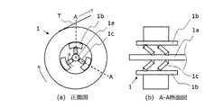
- An unwinding machine 1 shown in FIG. 1 unwinds a metal strip T wound in a coil shape in the direction of the arrow in the figure, and as shown in FIG. 2, a rotating shaft 1a, a gripping block 1b, and a connecting plate 1c. It has.
- the rotary shaft 1a can be rotated at a predetermined rotational speed by a motor (not shown) to be connected. Then, the rotating shaft 1a is rotated, and the gripping block 1b is pushed up by the connecting plate 1c in the outer peripheral direction, thereby gripping the inner diameter of the coiled metal strip T and rotating the metal strip T together with the rotating shaft 1a. Can do. Thereby, the unwinding machine 1 can unwind the metal strip T wound in a coil shape from the coil end portion and supply it to the cutter stand 2 via the tension adjusting unit 4 and the tension separating unit 5.
- the cutter stand 2 shown in FIG. 1 cuts and cuts the metal strip T unwound from the unwinding machine 1 to a narrow width, and as shown in FIG. I have.
- the rotary shafts 2a are arranged in a pair so as to sandwich the metal band T, and a plurality of rotary blades 2b are attached to the respective rotary shafts 2a at predetermined intervals. And the space
- the rotary shaft 2a can be rotated at a predetermined rotational speed in the direction of the arrow by a motor (not shown) to be connected. Then, by rotating the rotary shaft 2a, the plurality of rotary blades 2b rotate in the direction of the arrow in the figure, and the metal strip T supplied from the unwinder 1 can be sandwiched between the upper and lower rotary blades 2b. it can. As a result, the cutter stand 2 can feed and cut the metal band T at a predetermined speed while narrowly cutting it, and can supply the cut metal band T to the winder.
- a winder 3 shown in FIG. 1 winds a metal strip T cut into a cutter stand 2 in a coil shape, and includes a plurality of winding shafts 3a as shown in FIG.
- the plurality of winding shafts 3a can be rotated at a predetermined rotational speed in the direction of the arrow in the drawing by a motor (not shown) to be connected.
- the winder 3 rotates around the winding shaft 3a in synchronization with the winding jig 3b and the winding shaft 3a, and the air inside the winding shaft 3a.
- a pin 3c capable of pushing the inner periphery of the winding jig 3b with a force proportional to the applied pressure is provided. Thereby, the metal strip T can be wound up while being wound around the winding jig 3b.
- the tension adjusting unit 4 shown in FIG. 1 is arranged on the side of the unwinding machine 1 between the unwinding machine 1 and the cutter stand 2 and applies a constant tension to the metal strip T. As shown in FIG. , A roll 4a is provided that can move up and down in the figure and can apply a load to the metal strip T.
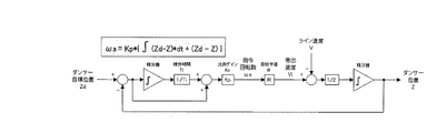
- the tension adjusting unit 4 of the present embodiment is a so-called dancer roll unit and is controlled together with the unwinding machine 1 so that when the tension of the metal strip T from the unwinding machine 1 fluctuates, the unwinding machine The rotational speed of 1 can be adjusted. Thereby, the up-and-down position of the roll 4a is kept constant, and the metal band T given a constant tension is discharged.
- the means for applying a constant tension to the metal strip T from the unwinder 1 will be described in more detail.
- the tension T fluctuates due to the deviation and change of the radius Ri of the metal strip T wound in a coil shape, and the variation T propagates to the band material and vibrates.
- the meander due to the fluctuation in tension is added to the meander of the strip itself. Therefore, based on the block diagram shown in FIG. 7, the rotational speed of the unwinder 1 is PI-controlled, the position of the dancer roll unit to which the constant thrust 2T is applied is controlled, and the peripheral speed acceleration / deceleration of the unwinder 1 is controlled. To suppress fluctuations in the tension itself.
- the tension separation unit 5 shown in FIG. 1 is arranged on the unwinding machine 1 side between the unwinding machine 1 and the cutter stand 2 and has a constant tension on the input side applied to the tension adjusting unit 4 and a metal on the output side. As shown in FIG. 1, a tension separating roll 5a is provided. The tension separating roll 5a can be rotated at a predetermined torque and rotation speed by a motor (not shown) to be connected.
- the tension separating unit 5 of the present embodiment is a so-called bridle roll unit.
- the tension of the bridle unit is added to or reduced from the entry side tension of the tension separation unit 5, thereby reducing the tension of the metal strip T on the output side.
- the tension adjustment unit 4 can be supplied with a lower tension.
- the tension applied to the metal strip T by the unwinding machine (hereinafter referred to as unwinding tension Fi) and the tension generated when the rotary blade 2b retracts the metal band T (hereinafter referred to as rotary blade retracting tension) are represented by Fc.
- the tension applied to the metal strip T by torque (hereinafter referred to as winding tension) is defined as Fo.
- tension adjusting unit 4 or tension separating unit 5 a cutting apparatus using a plurality of rotating shafts 2a and a plurality of rotating blades 2b as shown in FIG. It needs to be in a relationship.
- the rotary blade pulling tension Fc is made as small as possible, and the winding tension Fo is meandering.
- the minimum that does not generate vibration is desirable.
- the unwinding tension Fi is desirably maximized so that no breakage occurs.
- the present invention provides a metal band on the unwinder side between the unwinder and the cutter stand. Is provided with a tension adjusting unit for applying a constant tension. Furthermore, between the unwinder and the cutter stand, a tension separation unit is provided on the cutter stand side to separate the constant tension on the entry side and the tension on the exit side, and a damping force Fb is applied to the metal strip T at this position. Thus, the magnitude relationship of each tension is adjusted so that Fi ⁇ Fb ⁇ Fc + Fo. Thus, meandering and vibration are suppressed by the maximum unwinding tension Fi that does not break, the breaking is suppressed by the minimum winding tension Fo that does not meander and vibrate, and the rotary blade retracting tension Fc is minimized. Yes.
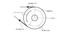
- the bridle roll unit drives the bridle roll by winding it around the roll when the wire or strip is transported in the longitudinal direction, using the frictional force of the roll surface so that the material does not slide against the bridle roll. A force is transmitted to the material to apply tension.
- a metal strip is passed through the two tension separating rolls 5a in an S shape.
- the bridle torque applied to the metal band is ⁇ b
- the radius of the bridle roll is R
- the tension of the metal band T at the position where the bridle roll and the metal band T first contact each other is F1
- the metal band T at the position where the bridle roll and the metal band T are separated is F2
- the following formula 1 is established.
- the tension of the metal strip T increases or decreases depending on the driving force of the bridle roll at the bridle roll carry-out source and the carry-out destination.
- the torque transmission condition that is, the condition that the material does not slide with respect to the bridle roll, is the case where the winding angle is ⁇ and the friction coefficient between the bridle roll and the material is ⁇ exp ( ⁇ ⁇ ⁇ ) ⁇ F1 / F2 ⁇ exp ( ⁇ ⁇ ⁇ ) It is. Note that if the number of bridle rolls is further increased, the tension of the metal strip T carried out therefrom can be further increased or decreased.
- the number of the tension separation rolls 5a can be appropriately changed according to a change in tension.
- the number of tension separating rolls 5a may be increased to three or more.
- the tension separating roll 5a is formed of a material having a high friction coefficient such as urethane rubber
- the roll 4a is formed of a metal material having a low friction coefficient such as stainless steel.
- the tension separating roll 5a The position of the metal strip T that is unwound from becomes constant, and meandering can be prevented. For this reason, it is possible to suppress meandering when the metal strip T is carried into the cutter stand.
- the roll 4a of the tension adjustment unit 4 has a maximum width in which the metal strip T unwound from the unwinder 1 meanders (one edge and the other edge of the metal strip T when meandering left and right). It is preferable that the surface is smooth in a range longer in the axial direction than the distance at the position where the two are farthest from each other.
- tensile_strength separation roll 5a and the surface of the roll 4a of the tension adjustment unit 4 differs 1.5 times or more, and also 2 times or more.
- a pinch roll unit can be substituted for the tension separation unit 5 of the present embodiment.
- the pinch roll unit requires a large pressing force on the surface sandwiching the metal strip T compared to the tension that increases or decreases, the bridle roll unit is applied to the tension separation unit 5 as in this embodiment. It is preferable to do.
- the tension of the metal band T (hereinafter referred to as post-damping tension Fi-Fb) reduced by the tension separation unit is preferably set to 0.3 MPa or more and 5 MPa or less.
- the meandering of the amorphous metal strip T and the occurrence of vibration can be suppressed.
- wear of the rotary blade can be sufficiently reduced.
- a more preferable lower limit value of the post-damping tension Fi-Fb is 0.4 MPa or more, and more preferably 0.5 MPa.
- a more preferable upper limit value of the post-damping tension Fi-Fb is 4 MPa or less, and more preferably 3 MPa or less.
- the post-damping tension Fi-Fb is preferably 0.3 MPa or more and 1.5 MPa or less. Furthermore, it is preferable to set it as 0.4 MPa or more and 1.3 MPa or less.
- the post-damping tension Fi-Fb is preferably 1 MPa or more and 5 MPa or less. Furthermore, it is preferable to set it as 1.5 MPa or more and 4 MPa or less.
- the unwinding tension Fi is preferably 1.5 times or more, more preferably 2 times or more of the post-damping tension Fi-Fb.
- the discharge speed from the unwinder of the metal strip can be increased, and the cutting speed can be increased.
- the cutting speed of the metal strip can be 75 m / min or more.
- the unwinding tension Fi is preferably more than 1.5 MPa. More preferably, it is preferably 1.7 MPa or more. However, the upper limit of the unwinding tension Fi is preferably 30 MPa or less in consideration of suppressing the fracture of the metal strip.
- the unwinding tension Fi is preferably more than 5 MPa. More preferably, it is preferable to set it as 5.5 MPa or more. In consideration of suppressing breakage of the metal strip, the upper limit of the unwinding tension Fi is preferably 30 MPa or less.
- the amorphous alloy ribbon T is not particularly limited as long as it has the most Fe (iron) composition among the contained metal elements. In addition to Fe, it is preferable to further contain Si (silicon) and B (boron).
- As the amorphous alloy ribbon T for example, an alloy obtained by melting the alloy having the above composition to a melting point or higher and rapidly solidifying it by a single roll method can be used.
- the composition of the amorphous metal band when the total content of Fe, Si, and B is 100 atomic%, the Fe content is 78 atomic% to 83 atomic%, and the Si content is 3%.
- examples thereof include an Fe-based amorphous alloy having an atomic percent of 10 to 10 atomic percent, a B content of 10 to 15 atomic percent, and the balance of impurities.
- the Fe content is 78 atomic% or more, the saturation magnetic flux density of the alloy ribbon becomes higher, so that an increase in size or weight of a magnetic core manufactured using the alloy ribbon is further suppressed.
- the Fe content is 83 atomic% or less, a decrease in the Curie point and a decrease in the crystallization temperature of the alloy are further suppressed, so that the stability of the magnetic properties of the magnetic core is further improved.
- the amorphous alloy may further contain C (carbon), which is an element contained in pure iron or the like that is a raw material for the molten alloy.
- the C (carbon) content is preferably 0.5 atomic% or less. When the C (carbon) content is 0.5 atomic% or less, embrittlement of the alloy ribbon is further suppressed.
- the C (carbon) content is preferably 0.1 atomic% to 0.5 atomic%. When the content of C (carbon) is 0.1 atomic% or more, the productivity of the molten alloy and the alloy ribbon is excellent.
- An amorphous metal band that can be nanocrystallized can also be used.
- an amorphous metal band which can be nanocrystallized for example, an alloy having a composition represented by the general formula: (Fe1-aMa) 100-xyz- ⁇ - ⁇ - ⁇ CuxSiyBzM′ ⁇ M ′′ ⁇ X ⁇ (atomic%) Can be used.
- M is Co and / or Ni
- M ′ is at least one element selected from the group consisting of Nb, Mo, Ta, Ti, Zr, Hf, V, Cr, Mn and W
- M ′′ is A1
- X is selected from the group consisting of C, Ge, P, Ga, Sb, In, Be, As.
- X is at least one element selected from the group consisting of C, Ge, P, Ga, Sb, In, As, Be, and a, x, y, z, ⁇ , ⁇ and ⁇ are 0 ⁇ a ⁇ 0.5, 0.1 ⁇ x ⁇ 3, 0 ⁇ y ⁇ 30, 0 ⁇ z ⁇ 25, 5 ⁇ y + z ⁇ 30, 0 ⁇ ⁇ ⁇ 20, 0 ⁇ ⁇ ⁇ , respectively. 20 and 0 ⁇ ⁇ ⁇ 20 are satisfied.
- amorphous metal strip alloy ribbons having a thickness of 7 ⁇ m to 50 ⁇ m can be used.
- the thickness of the alloy ribbon is preferably 9 ⁇ m or more.
- the thickness is 50 ⁇ m or less, a stable amorphous state can be obtained in the alloy ribbon.
- the thickness of the alloy ribbon is more preferably 30 ⁇ m or less.
- the width of the amorphous metal band (that is, the length in the width direction) is preferably 30 mm to 1000 mm.
- the width is 30 mm or more, a large-capacity and practical transformer can be obtained. Furthermore, if the width is 100 mm or more, the necessity for reducing the excitation power increases. Therefore, the amorphous metal strip in which the excitation power is reduced is particularly suitable as a wide alloy ribbon having a width of 100 mm or more.
- the width of the amorphous metal strip is 1000 mm or less, the productivity (manufacturability) is excellent.
- the width of the amorphous metal strip is more preferably 500 mm or less, further preferably 400 mm or less, and particularly preferably 300 mm or less.
- the rotating shaft 1 a is rotated at a predetermined number of revolutions, the metal strip T wound in a coil shape is unwound in the direction of the end of the coil, and supplied to the tension adjusting unit 4.
- the tension adjustment unit 4 a load is applied from the roll 4 a to the metal band T, and a constant tension is applied to the metal band T.
- the number of rotations of the unwinder 1 is adjusted according to the fluctuation of the tension of the metal strip T, and the vertical position of the roll 4a is kept constant to maintain the constant tension.
- the metal strip T to which a constant tension is applied is supplied to the tension separation unit 5.
- the slitter device of the present embodiment can apply a proper constant tension to the metal strip T by having the tension adjusting unit 5. Thereby, the amplitude of the vibration of the metal strip T can be reduced, and even if the metal strip T is unwound from the unwinder 1 at a high speed, the occurrence of vibration that greatly affects the cutting accuracy can be suppressed.
- the slitter device that supplies the metal strip while applying a constant tension as in the present embodiment is an effective device for cutting and cutting the amorphous metal strip.
- the torque and rotation speed of the tension separation roll 5 a are adjusted by a motor (not shown) to separate the tension before and after the tension separation unit 5.
- the tension separation unit 5 is arranged on the unwinding machine 1 side between the unwinding machine 1 and the cutter stand 2.
- the distance between the tension separating unit 5 and the cutter stand 5 is preferably as narrow as possible. Thereby, it can suppress that the metal strip T newly vibrates between the tension separation unit 5 and the cutter stand 5.
- the metal strip T is striped and cut into a narrow metal strip T by the plurality of rotary blades 2b of the cutter stand 2. Then, the strip-cut metal strip T is supplied to the winder 3.
- the slitter device of the present embodiment can suppress the occurrence of vibration even when the metal band T is supplied to the cutter stand 2 quickly, so that the metal band T can be cut at high speed and with high accuracy. it can.
- the slitter device of the present embodiment can reduce the tension of the metal strip T supplied to the cutter stand 2 by having the tension separating unit 5. Thereby, the reaction force which acts on the rotary blade 2b from the metal strip T can be reduced, and the life of the rotary blade 2b can be extended.
- the slitter device that reduces the tension of the metal strip T supplied to the cutter stand 2 is an effective device for cutting off the amorphous metal strip.
- the plurality of winding shafts 3a are rotated at a predetermined rotational speed by a motor (not shown), and the striped and cut metal strip T is wound into a coil shape.
- the metal strip T when winding the metal strip T, it is preferable to rotate the winding shaft 3a faster than the rotational speed necessary for winding. By doing so, a speed difference can be generated between the inner diameters of the winding shaft 3a and the winding jig 3b, and the pin 3c is slid along the inner diameter of the wound metal strip T to apply tension.
- the metal strip T can be wound up. That is, the metal strip T supplied from the cutter stand 2 can be wound while being tightened.
- the slitter device of the present embodiment includes the tension adjusting unit 4 that applies a constant tension to the metal strip T between the unwinder 1 and the cutter stand 2 on the unwinder 1 side.
- a tension separation unit 5 is provided on the cutter stand side to separate the constant tension on the input side from the tension on the output side.
- tensile_strength of the metal strip T supplied to the cutter stand 2 can be made small by the tension
- the lifetime of the rotary blade 2b of the cutter stand 2 can also be lengthened.
- FIG. 1 Compared to the embodiment of FIG. 1, a plurality of guide rolls 6 a are arranged in a path until the metal strip T discharged from the tension separation unit 5 is carried into the cutter stand 2. Further, a guide mechanism 7 for guiding the metal strip T from the vertical direction and the width direction is disposed between the plurality of guide rolls 6 a and the cutter stand 2.
- a plurality of guide rolls 6a are arranged, and although two are arranged in FIG. 8, three or more may be arranged. By disposing the guide roll 6a, when conveying the metal band T with reduced tension, it is possible to guide to the cutter stand 2 so that the metal band T does not tilt.
- the guide mechanism 7 is constituted by a plurality of guide plates 7a, and guides the metal strip T from the vertical direction (front and back direction) and the width direction. A slight gap exists between the guide plate 7a and the metal strip T.
- the amorphous metal band has been described as an example of the metal band to be cut and cut.
- the slitter device of the present invention can be used for cutting and cutting metal bands other than the amorphous metal band. it can.
- the life of the rotary blade of the cuttertand can be extended by applying to the cutting and cutting of hard metal bands, for example, the cutting of niobium, chromium and nickel metal bands.
- an amorphous metal strip (product name: 2605SA1) manufactured by Hitachi Metals, Ltd. was used.
- the width of the amorphous metal band was 170 mm before cutting.
- the thickness was in the range of 22-24 ⁇ m.
- the cutting speed of the amorphous metal strip was set to 75 m / min and 100 m / min.
- the width after cutting and cutting was 25 mm.
- the number of metal strips to be striped at one time was changed to 1, 4, and 6, and the strips were cut.
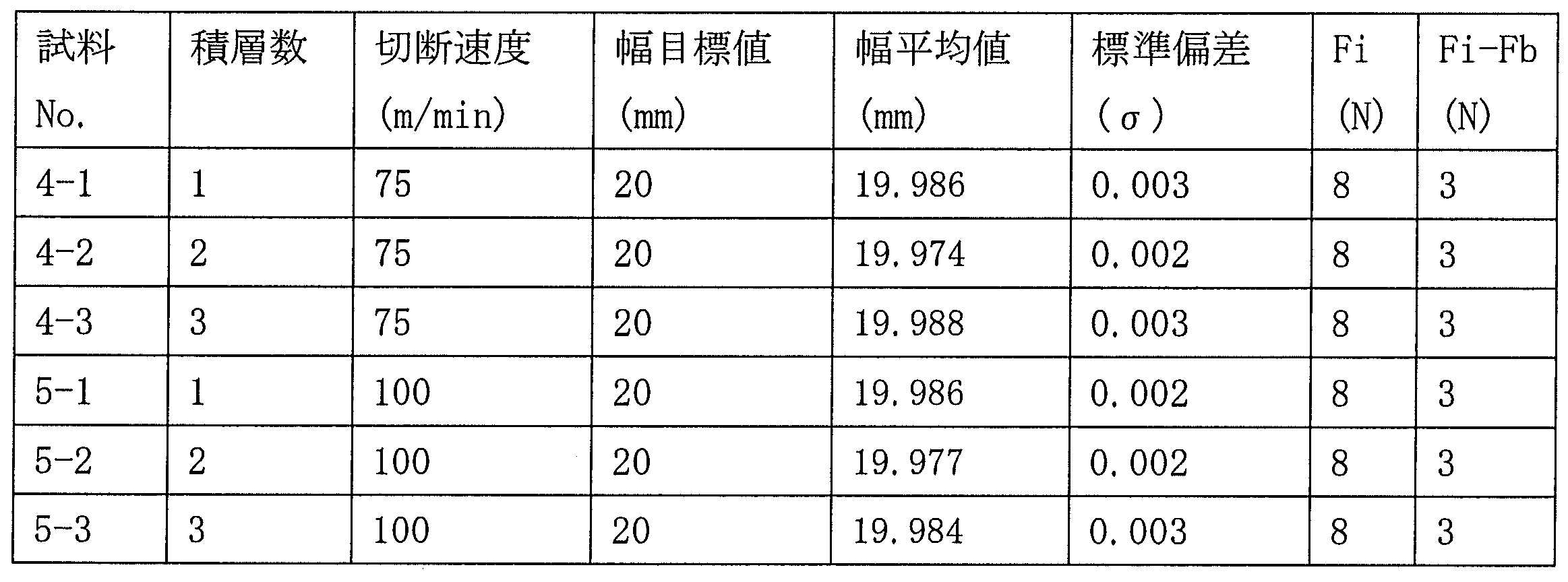
- the unwinding tension Fi is 2 MPa (about 8 N).
- the post-damping tension Fi-Fb was set to 0.8 MPa (about 3N).
- the number of lines to be taken is 1 and the cutting speed width is 24.980 mm on the average with respect to the target value of 25 mm, and the error is within 0.002 mm or less with respect to the target width. It was confirmed that cutting was possible.
- a slitting device without a tension separation unit was used for cutting and cutting.
- the same metal band T was used.
- the cutting speed of the amorphous metal band was 70 m / min. Further, the width after cutting and cutting was 20 mm.
- the measurement results of the comparative examples are shown in Table 1 as Sample Nos. 3-1 and 3-2.
- the standard deviation ( ⁇ ) of the width of the slit metal band tends to be smaller as the cutting speed is faster and the width after the cutting is wider.
- the slit metal bands of Samples Nos. 3-1 and 3-2 obtained as Comparative Examples have a slow cutting speed (70 m / min) and a narrow standard deviation in width even though the width is narrow. 0.005 to 0.006, which is larger than that using the slitter device of the present invention.
- an amorphous metal band capable of nanocrystallization (amorphous metal band (product name: FT-3) manufactured by Hitachi Metals) was used.
- the amorphous metal band having a width of 63 mm was used.
- the thickness was in the range of 15-21 ⁇ m.
- the cutting speed of the amorphous metal strip was set to 75 m / min and 100 m / min.
- the width after cutting and cutting was 25 mm.
- the number of metal strips to be striped at one time was changed to 1, 2, 3 and striped and cut.
- the unwinding tension Fi is 7 MPa (about 8 N).
- the post-damping tension Fi-Fb was 2.6 MPa.
Landscapes
- Engineering & Computer Science (AREA)
- Mechanical Engineering (AREA)
- Life Sciences & Earth Sciences (AREA)
- Forests & Forestry (AREA)
- Winding, Rewinding, Material Storage Devices (AREA)
- Shearing Machines (AREA)
Abstract
Description
巻出された前記金属帯を狭幅に条取り切断するカッタスタンドと、切断された前記金属帯をコイル状に巻取る巻取機とを有するスリッタ装置を用いた、金属帯のスリット方法であって、
前記巻出機と前記カッタスタンドとの間の巻出し機側に配置された張力調整ユニットにより、前記金属帯に一定張力を付与する工程と、
前記巻出機と前記カッタスタンドとの間の前記カッタスタンド側に配置された張力分離ユニットにより、入側の前記一定張力と出側の張力とを隔てる工程と、
前記張力分離工程により、金属帯に付与されている張力を減衰させて、前記金属帯を前記カッタスタンドに供給する工程と、
を有する金属帯のスリット方法である。
そこで本発明では、前記一般帯材の相反問題に加え、アモルファス特有の問題を解決する手段として、破断しない極力強い張力で巻出し、かつ回転刃直前まで搬送を行い、回転刃直前では破断も蛇行もしない極力弱い張力にまで減衰させて、回転刃に挿材する方法を見出した。以下その実施形態について、詳細に説明する。
図1に示す巻出機1は、コイル状に巻かれた金属帯Tを、図の矢印方向に巻出すものであり、図2に示すように、回転軸1a、把持ブロック1b、接続板1cを備えている。
図1に示すカッタスタンド2は、巻出機1から巻出された金属帯Tを、狭幅に条取り切断するものであり、図3に示すように、回転軸2aと回転刃2bとを備えている。回転軸2aは、金属帯Tを挟むように、上下一対にして配されていて、それぞれの回転軸2aに対して、複数の回転刃2bが所定の間隔にして取り付けられている。そして、回転軸2aの間隔は、上下の回転刃2bが噛み合う間隔に調整されている。
図1に示す巻取機3は、カッタスタンド2に切断された金属帯Tを、コイル状に巻き取るものであり、図4に示すように、複数の巻取軸3aを備えている。そして、複数の巻取軸3aは、接続する不図示のモータにより、図の矢印方向に所定の回転数にて回転することができる。
図1に示す張力調整ユニット4は、巻出機1とカッタスタンド2の間の、巻出機1側に配され、金属帯Tに一定張力を付与するものであり、図5に示すように、図の上下に移動可能にして金属帯Tに荷重付加できる、ロール4aを備えている。
巻出機1からの金属帯Tに一定張力を付与する手段についてさらに詳細を述べる。
図1に示す張力分離ユニット5は、巻出機1とカッタスタンド2の間の、巻出機1側に配され、張力調整ユニット4に付与された入側の一定張力と、出側の金属帯Tの張力とを隔てるものであり、図1に示すように、張力分離ロール5aを備えている。張力分離ロール5aは、接続する不図示のモータにより、所定のトルクと回転数にて回転することができる。
ブライドルトルクτb=R×(F1-F2)
exp(-μ×θ)≦F1/F2≦exp(μ×θ)
である。なお、さらにブライドルロールの段数を増やせば、さらにそこから搬出する金属帯Tの張力を増減することができる。
張力分離ユニット5を構成する張力分離ロール5aの表面と、張力調整ユニット4のロール4aの表面を比較した場合、ロール4aの表面は、張力分離ロール5aの表面よりも、金属帯Tに対して平滑になるようにしている。具体的には、張力分離ロール5aをウレタンゴム等の摩擦係数の高い材質で形成し、ロール4aをステンレス等の摩擦係数の低い金属材質で形成する。
具体的には、ナノ結晶化しないアモルファス金属帯の場合は、減衰後張力Fi―Fbは0.3MPa以上1.5MPa以下とすることが好ましい。さらには0.4MPa以上1.3MPa以下とすることが好ましい。
つぎに、本発明のスリッタ装置の別実施形態を図8により説明する。図1の実施形態に比べて、張力分離ユニット5から排出された金属帯Tがカッタスタンド2に搬入されるまでの経路に複数の案内ロール6aを配置している。さらに、複数の案内ロール6aとカッタスタンド2の間には、金属帯Tを上下方向および幅方向からガイドするガイド機構7が配置されている。
以下に、上記の本発明のスリッタ装置を用いてアモルファス金属帯の条取り切断を行った例を示す。

1a:回転軸、1b:把持ブロック、1c:接続板
2:カッタスタンド
2a:回転軸、2b:回転刃
3:巻取機
3a:巻取軸、3b:巻取り治具、3c:ピン
4:張力調整ユニット
4a:ロール
5:張力分離ユニット
5a:張力減衰ロール
6a:案内ロール
7:ガイド機構
7a:ガイド板
Fi:巻出張力
Fb:減衰張力
Fc:回転刃引込張力
Fo:巻取張力
Claims (11)
- コイル状に巻かれた金属帯を巻出す巻出機と、
巻出された前記金属帯を狭幅に条取り切断するカッタスタンドと、
切断された前記金属帯をコイル状に巻取る巻取機と、
を有する金属帯のスリッタ装置であって、
前記巻出機と前記カッタスタンドとの間には、
前記巻出機側に、前記金属帯に一定張力を付与する張力調整ユニットを有し、
前記カッタスタンド側に、入側の前記一定張力と出側の張力とを隔てる張力分離ユニットを有する、
ことを特徴とする金属帯のスリッタ装置。 - 前記張力調整ユニットを構成するロールの表面は、前記張力分離ユニットを構成するロールの表面よりも平滑であることを特徴とする金属帯のスリッタ装置。
- 前記張力分離ユニットから排出された金属帯が前記カッタスタンドに搬入されるまでの経路に複数の案内ロールを配置したことを特徴とする請求項1又は2に記載の金属帯のスリッタ装置。
- 前記複数の案内ロールと前記カッタスタンドとの間には、金属帯を上下方向および幅方向からガイドするガイド機構を備えたことを特徴とする請求項3に記載の金属帯のスリッタ装置。
- 前記張力分離ユニットが、ブライドルロールユニットであることを特徴とする請求項1~4のいずれか1項に記載の金属帯のスリッタ装置。
- 前記金属帯が、アモルファス金属帯であることを特徴とする請求項1~5のいずれか1項に記載の金属帯のスリッタ装置。
- コイル状に巻かれた金属帯を巻出す巻出機と、
巻出された前記金属帯を狭幅に条取り切断するカッタスタンドと、
切断された前記金属帯をコイル状に巻取る巻取機と
を有するスリッタ装置を用いた、金属帯のスリット方法であって、
前記巻出機と前記カッタスタンドとの間の前記巻出機側に配置された張力調整ユニットにより、前記金属帯に一定張力を付与する工程と、
前記巻出機と前記カッタスタンドとの間の前記カッタスタンド側に配置された張力分離ユニットにより、入側の前記一定張力と出側の張力とを隔てる工程と、
前記張力分離工程により、金属帯に付与されている張力を減衰させて、前記金属帯を前記カッタスタンドに供給する工程と、
を有することを特徴とする金属帯のスリット方法。 - 前記減衰後の張力(Fi―Fb)を0.3MPa以上5MPa以下としたことを特徴とする請求項7に記載の金属帯のスリット方法。
- 前記張力調整工程において、前記巻出機から前記金属帯を排出する際の金属帯の長手方向に付与される張力(巻出張力Fi)を、前記減衰後張力(Fi―Fb)に対して、1.5倍以上としたことを特徴とする請求項8に記載の金属帯のスリット方法。
- 前記金属帯は、厚みが7μm以上50μm以下、幅が100mm以上1000mm以下のアモルファス金属帯を用いることを特徴とする請求項7~9のいずれか1項に記載の金属帯のスリット方法。
- 前記カッタスタンドによってスリットされた金属帯の幅は30mm以下であることを特徴とする請求項7~10のいずれか1項に記載の金属帯のスリット方法。
Priority Applications (4)
| Application Number | Priority Date | Filing Date | Title |
|---|---|---|---|
| US15/764,156 US11014134B2 (en) | 2015-09-29 | 2016-09-29 | Metal band slitter device and slitting method |
| CN201680056869.5A CN108136466B (zh) | 2015-09-29 | 2016-09-29 | 金属带的分切装置以及分切方法 |
| KR1020187011460A KR102339343B1 (ko) | 2015-09-29 | 2016-09-29 | 금속 밴드의 슬리터 장치 및 슬리팅 방법 |
| JP2016570364A JP6183736B1 (ja) | 2015-09-29 | 2016-09-29 | 金属帯のスリッタ装置及びスリット方法 |
Applications Claiming Priority (2)
| Application Number | Priority Date | Filing Date | Title |
|---|---|---|---|
| JP2015-190640 | 2015-09-29 | ||
| JP2015190640 | 2015-09-29 |
Publications (1)
| Publication Number | Publication Date |
|---|---|
| WO2017057591A1 true WO2017057591A1 (ja) | 2017-04-06 |
Family
ID=58424139
Family Applications (1)
| Application Number | Title | Priority Date | Filing Date |
|---|---|---|---|
| PCT/JP2016/078853 Ceased WO2017057591A1 (ja) | 2015-09-29 | 2016-09-29 | 金属帯のスリッタ装置及びスリット方法 |
Country Status (5)
| Country | Link |
|---|---|
| US (1) | US11014134B2 (ja) |
| JP (1) | JP6183736B1 (ja) |
| KR (1) | KR102339343B1 (ja) |
| CN (1) | CN108136466B (ja) |
| WO (1) | WO2017057591A1 (ja) |
Cited By (2)
| Publication number | Priority date | Publication date | Assignee | Title |
|---|---|---|---|---|
| WO2019059070A1 (ja) * | 2017-09-21 | 2019-03-28 | 日立金属株式会社 | 金属帯のスリッタ装置 |
| CN111958123A (zh) * | 2019-09-30 | 2020-11-20 | 广东利元亨智能装备股份有限公司 | 一种极耳成型及分切设备 |
Families Citing this family (6)
| Publication number | Priority date | Publication date | Assignee | Title |
|---|---|---|---|---|
| KR102112225B1 (ko) * | 2019-11-18 | 2020-05-18 | 김은환 | 스틸밴드 가공장치 및 가공방법 |
| CN111354563A (zh) * | 2020-04-14 | 2020-06-30 | 全球能源互联网研究院有限公司 | 阳极饱和电抗器用铁心、制备方法及阳极饱和电抗器 |
| CN112209156B (zh) * | 2020-10-26 | 2022-12-06 | 瓯锟科技温州有限公司 | 一种金属复合板快速分卷装置 |
| CN114101776B (zh) * | 2021-11-08 | 2023-03-14 | 武汉钢铁有限公司 | 一种圆盘剪厚薄过渡及升降速过程边浪控制方法 |
| CN115741820B (zh) * | 2022-12-15 | 2025-09-09 | 江西华起装备制造有限公司 | 一种同步带整模割带机 |
| US20260208996A1 (en) * | 2025-01-20 | 2026-07-23 | Kingnode America Inc. | Automatic slitting machine and working method thereof |
Citations (4)
| Publication number | Priority date | Publication date | Assignee | Title |
|---|---|---|---|---|
| JPS5265156A (en) * | 1975-11-27 | 1977-05-30 | Nippon Kokan Kk | Method of controlling tension in continuous equipment for steel band |
| JPH05177253A (ja) * | 1992-01-04 | 1993-07-20 | Kataoka Mach Co Ltd | スリッターリワインダー及び帯状シートの矯正装置 |
| JP2004160513A (ja) * | 2002-11-14 | 2004-06-10 | Hitachi Metals Ltd | シールド材の製造方法 |
| JP2015110324A (ja) * | 2013-11-06 | 2015-06-18 | 三起機械株式会社 | 長尺紙印刷方法及び長尺紙印刷機 |
Family Cites Families (4)
| Publication number | Priority date | Publication date | Assignee | Title |
|---|---|---|---|---|
| JPH0327804A (ja) * | 1989-06-26 | 1991-02-06 | Kawasaki Steel Corp | 熱延鋼板のスキンパス・スリッタコンビネーションライン |
| JPH1076417A (ja) * | 1996-08-30 | 1998-03-24 | Mitsui High Tec Inc | 多条切断スリッタ装置 |
| DE102007006809B4 (de) * | 2007-02-07 | 2009-04-16 | Bwg Bergwerk- Und Walzwerk-Maschinenbau Gmbh | Verfahren und Vorrichtung zum kontinuierlichen Zugrecken eines Metallbandes |
| CN101439468B (zh) * | 2008-12-31 | 2010-12-08 | 中国重型机械研究院 | 拉弯矫直重卷机组工艺 |
-
2016
- 2016-09-29 CN CN201680056869.5A patent/CN108136466B/zh active Active
- 2016-09-29 JP JP2016570364A patent/JP6183736B1/ja active Active
- 2016-09-29 US US15/764,156 patent/US11014134B2/en active Active
- 2016-09-29 KR KR1020187011460A patent/KR102339343B1/ko active Active
- 2016-09-29 WO PCT/JP2016/078853 patent/WO2017057591A1/ja not_active Ceased
Patent Citations (4)
| Publication number | Priority date | Publication date | Assignee | Title |
|---|---|---|---|---|
| JPS5265156A (en) * | 1975-11-27 | 1977-05-30 | Nippon Kokan Kk | Method of controlling tension in continuous equipment for steel band |
| JPH05177253A (ja) * | 1992-01-04 | 1993-07-20 | Kataoka Mach Co Ltd | スリッターリワインダー及び帯状シートの矯正装置 |
| JP2004160513A (ja) * | 2002-11-14 | 2004-06-10 | Hitachi Metals Ltd | シールド材の製造方法 |
| JP2015110324A (ja) * | 2013-11-06 | 2015-06-18 | 三起機械株式会社 | 長尺紙印刷方法及び長尺紙印刷機 |
Cited By (2)
| Publication number | Priority date | Publication date | Assignee | Title |
|---|---|---|---|---|
| WO2019059070A1 (ja) * | 2017-09-21 | 2019-03-28 | 日立金属株式会社 | 金属帯のスリッタ装置 |
| CN111958123A (zh) * | 2019-09-30 | 2020-11-20 | 广东利元亨智能装备股份有限公司 | 一种极耳成型及分切设备 |
Also Published As
| Publication number | Publication date |
|---|---|
| CN108136466A (zh) | 2018-06-08 |
| KR102339343B1 (ko) | 2021-12-14 |
| US11014134B2 (en) | 2021-05-25 |
| JP6183736B1 (ja) | 2017-08-23 |
| JPWO2017057591A1 (ja) | 2017-10-05 |
| US20180272402A1 (en) | 2018-09-27 |
| KR20180061252A (ko) | 2018-06-07 |
| CN108136466B (zh) | 2020-05-19 |
Similar Documents
| Publication | Publication Date | Title |
|---|---|---|
| JP6183736B1 (ja) | 金属帯のスリッタ装置及びスリット方法 | |
| JP6298489B2 (ja) | アモルファス合金リボンを処理するためのシステム及び方法 | |
| CN109863253B (zh) | 合金带用退火装置以及退火合金带的制造方法 | |
| US8375569B2 (en) | Apparatus for manufacturing a transformer core | |
| CN101371321B (zh) | 纳米结晶材料的带材的生产方法和由所述带材生产卷绕芯的设备 | |
| CN102006946B (zh) | 圆盘传送带卷轴设备 | |
| CN114411069A (zh) | 纳米晶合金的前体的宽的铁基非晶态合金 | |
| JP5639858B2 (ja) | インゴットの切断方法 | |
| JP6665971B2 (ja) | 金属帯のスリッタ装置 | |
| JP6681024B2 (ja) | 刃物用金属条コイルの製造方法 | |
| JP2011240461A (ja) | ガングスリッタ装置 | |
| JP2018056336A (ja) | 積層体及び複合積磁心 | |
| JP6850418B2 (ja) | 金属条の製造方法 | |
| JP5090788B2 (ja) | スリッティング装置 | |
| KR20230167524A (ko) | 필름 적층이 가능한 금속 판재의 슬리터 장치 | |
| JP7736051B2 (ja) | 金属帯巻き取り用セグメント、マンドレル、巻き取り装置、プロセスライン、金属帯の巻き取り方法及び高張力鋼板の製造方法 | |
| CN112660866A (zh) | 重卷卷绕的材料幅的方法和重卷装置 | |
| US20250129447A1 (en) | Methodfor manufacturing nanocrystal alloy ribbon, and method for manufacturing magnetic sheet | |
| JP2004160513A (ja) | シールド材の製造方法 | |
| JP2002337232A (ja) | 積層薄帯の製造方法および製造装置 | |
| JP2025103681A (ja) | 巻回コアとその製造方法、および磁性部品 | |
| SU904924A1 (ru) | Автоматическа лини дл раскро рулонного материала на длинномерные заготовки с непараллельными боковыми кромками | |
| CN115443423A (zh) | 具有分切耳部的偏移防止机构的制造光学膜带卷筒的装置以及方法 | |
| JPH06210303A (ja) | 薄肉材の連続圧延方法およびその装置 | |
| JP2016032823A (ja) | 連続式圧延ラインにおける巻取制御方法 |
Legal Events
| Date | Code | Title | Description |
|---|---|---|---|
| ENP | Entry into the national phase |
Ref document number: 2016570364 Country of ref document: JP Kind code of ref document: A |
|
| 121 | Ep: the epo has been informed by wipo that ep was designated in this application |
Ref document number: 16851762 Country of ref document: EP Kind code of ref document: A1 |
|
| WWE | Wipo information: entry into national phase |
Ref document number: 15764156 Country of ref document: US |
|
| NENP | Non-entry into the national phase |
Ref country code: DE |
|
| ENP | Entry into the national phase |
Ref document number: 20187011460 Country of ref document: KR Kind code of ref document: A |
|
| 122 | Ep: pct application non-entry in european phase |
Ref document number: 16851762 Country of ref document: EP Kind code of ref document: A1 |