WO2017057552A1 - 透明アルミナ焼結体の製法 - Google Patents
透明アルミナ焼結体の製法 Download PDFInfo
- Publication number
- WO2017057552A1 WO2017057552A1 PCT/JP2016/078789 JP2016078789W WO2017057552A1 WO 2017057552 A1 WO2017057552 A1 WO 2017057552A1 JP 2016078789 W JP2016078789 W JP 2016078789W WO 2017057552 A1 WO2017057552 A1 WO 2017057552A1
- Authority
- WO
- WIPO (PCT)
- Prior art keywords
- alumina
- mass
- powder
- sintered body
- raw material
- Prior art date
- Legal status (The legal status is an assumption and is not a legal conclusion. Google has not performed a legal analysis and makes no representation as to the accuracy of the status listed.)
- Ceased
Links
Images


Classifications
-
- C—CHEMISTRY; METALLURGY
- C04—CEMENTS; CONCRETE; ARTIFICIAL STONE; CERAMICS; REFRACTORIES
- C04B—LIME, MAGNESIA; SLAG; CEMENTS; COMPOSITIONS THEREOF, e.g. MORTARS, CONCRETE OR LIKE BUILDING MATERIALS; ARTIFICIAL STONE; CERAMICS; REFRACTORIES; TREATMENT OF NATURAL STONE
- C04B35/00—Shaped ceramic products characterised by their composition; Ceramics compositions; Processing powders of inorganic compounds preparatory to the manufacturing of ceramic products
- C04B35/01—Shaped ceramic products characterised by their composition; Ceramics compositions; Processing powders of inorganic compounds preparatory to the manufacturing of ceramic products based on oxide ceramics
- C04B35/10—Shaped ceramic products characterised by their composition; Ceramics compositions; Processing powders of inorganic compounds preparatory to the manufacturing of ceramic products based on oxide ceramics based on aluminium oxide
- C04B35/111—Fine ceramics
- C04B35/115—Translucent or transparent products
-
- B—PERFORMING OPERATIONS; TRANSPORTING
- B32—LAYERED PRODUCTS
- B32B—LAYERED PRODUCTS, i.e. PRODUCTS BUILT-UP OF STRATA OF FLAT OR NON-FLAT, e.g. CELLULAR OR HONEYCOMB, FORM
- B32B18/00—Layered products essentially comprising ceramics, e.g. refractory products
-
- C—CHEMISTRY; METALLURGY
- C04—CEMENTS; CONCRETE; ARTIFICIAL STONE; CERAMICS; REFRACTORIES
- C04B—LIME, MAGNESIA; SLAG; CEMENTS; COMPOSITIONS THEREOF, e.g. MORTARS, CONCRETE OR LIKE BUILDING MATERIALS; ARTIFICIAL STONE; CERAMICS; REFRACTORIES; TREATMENT OF NATURAL STONE
- C04B35/00—Shaped ceramic products characterised by their composition; Ceramics compositions; Processing powders of inorganic compounds preparatory to the manufacturing of ceramic products
- C04B35/622—Forming processes; Processing powders of inorganic compounds preparatory to the manufacturing of ceramic products
- C04B35/626—Preparing or treating the powders individually or as batches ; preparing or treating macroscopic reinforcing agents for ceramic products, e.g. fibres; mechanical aspects section B
- C04B35/62605—Treating the starting powders individually or as mixtures
- C04B35/6261—Milling
- C04B35/6262—Milling of calcined, sintered clinker or ceramics
-
- C—CHEMISTRY; METALLURGY
- C04—CEMENTS; CONCRETE; ARTIFICIAL STONE; CERAMICS; REFRACTORIES
- C04B—LIME, MAGNESIA; SLAG; CEMENTS; COMPOSITIONS THEREOF, e.g. MORTARS, CONCRETE OR LIKE BUILDING MATERIALS; ARTIFICIAL STONE; CERAMICS; REFRACTORIES; TREATMENT OF NATURAL STONE
- C04B35/00—Shaped ceramic products characterised by their composition; Ceramics compositions; Processing powders of inorganic compounds preparatory to the manufacturing of ceramic products
- C04B35/622—Forming processes; Processing powders of inorganic compounds preparatory to the manufacturing of ceramic products
- C04B35/64—Burning or sintering processes
- C04B35/645—Pressure sintering
-
- C—CHEMISTRY; METALLURGY
- C04—CEMENTS; CONCRETE; ARTIFICIAL STONE; CERAMICS; REFRACTORIES
- C04B—LIME, MAGNESIA; SLAG; CEMENTS; COMPOSITIONS THEREOF, e.g. MORTARS, CONCRETE OR LIKE BUILDING MATERIALS; ARTIFICIAL STONE; CERAMICS; REFRACTORIES; TREATMENT OF NATURAL STONE
- C04B35/00—Shaped ceramic products characterised by their composition; Ceramics compositions; Processing powders of inorganic compounds preparatory to the manufacturing of ceramic products
- C04B35/622—Forming processes; Processing powders of inorganic compounds preparatory to the manufacturing of ceramic products
- C04B35/64—Burning or sintering processes
- C04B35/645—Pressure sintering
- C04B35/6455—Hot isostatic pressing
-
- G—PHYSICS
- G02—OPTICS
- G02B—OPTICAL ELEMENTS, SYSTEMS OR APPARATUS
- G02B1/00—Optical elements characterised by the material of which they are made; Optical coatings for optical elements
- G02B1/02—Optical elements characterised by the material of which they are made; Optical coatings for optical elements made of crystals, e.g. rock-salt, semi-conductors
-
- C—CHEMISTRY; METALLURGY
- C04—CEMENTS; CONCRETE; ARTIFICIAL STONE; CERAMICS; REFRACTORIES
- C04B—LIME, MAGNESIA; SLAG; CEMENTS; COMPOSITIONS THEREOF, e.g. MORTARS, CONCRETE OR LIKE BUILDING MATERIALS; ARTIFICIAL STONE; CERAMICS; REFRACTORIES; TREATMENT OF NATURAL STONE
- C04B2235/00—Aspects relating to ceramic starting mixtures or sintered ceramic products
- C04B2235/02—Composition of constituents of the starting material or of secondary phases of the final product
- C04B2235/30—Constituents and secondary phases not being of a fibrous nature
- C04B2235/32—Metal oxides, mixed metal oxides, or oxide-forming salts thereof, e.g. carbonates, nitrates, (oxy)hydroxides, chlorides
- C04B2235/3205—Alkaline earth oxides or oxide forming salts thereof, e.g. beryllium oxide
- C04B2235/3206—Magnesium oxides or oxide-forming salts thereof
-
- C—CHEMISTRY; METALLURGY
- C04—CEMENTS; CONCRETE; ARTIFICIAL STONE; CERAMICS; REFRACTORIES
- C04B—LIME, MAGNESIA; SLAG; CEMENTS; COMPOSITIONS THEREOF, e.g. MORTARS, CONCRETE OR LIKE BUILDING MATERIALS; ARTIFICIAL STONE; CERAMICS; REFRACTORIES; TREATMENT OF NATURAL STONE
- C04B2235/00—Aspects relating to ceramic starting mixtures or sintered ceramic products
- C04B2235/02—Composition of constituents of the starting material or of secondary phases of the final product
- C04B2235/30—Constituents and secondary phases not being of a fibrous nature
- C04B2235/32—Metal oxides, mixed metal oxides, or oxide-forming salts thereof, e.g. carbonates, nitrates, (oxy)hydroxides, chlorides
- C04B2235/3217—Aluminum oxide or oxide forming salts thereof, e.g. bauxite, alpha-alumina
-
- C—CHEMISTRY; METALLURGY
- C04—CEMENTS; CONCRETE; ARTIFICIAL STONE; CERAMICS; REFRACTORIES
- C04B—LIME, MAGNESIA; SLAG; CEMENTS; COMPOSITIONS THEREOF, e.g. MORTARS, CONCRETE OR LIKE BUILDING MATERIALS; ARTIFICIAL STONE; CERAMICS; REFRACTORIES; TREATMENT OF NATURAL STONE
- C04B2235/00—Aspects relating to ceramic starting mixtures or sintered ceramic products
- C04B2235/02—Composition of constituents of the starting material or of secondary phases of the final product
- C04B2235/30—Constituents and secondary phases not being of a fibrous nature
- C04B2235/32—Metal oxides, mixed metal oxides, or oxide-forming salts thereof, e.g. carbonates, nitrates, (oxy)hydroxides, chlorides
- C04B2235/3217—Aluminum oxide or oxide forming salts thereof, e.g. bauxite, alpha-alumina
- C04B2235/322—Transition aluminas, e.g. delta or gamma aluminas
-
- C—CHEMISTRY; METALLURGY
- C04—CEMENTS; CONCRETE; ARTIFICIAL STONE; CERAMICS; REFRACTORIES
- C04B—LIME, MAGNESIA; SLAG; CEMENTS; COMPOSITIONS THEREOF, e.g. MORTARS, CONCRETE OR LIKE BUILDING MATERIALS; ARTIFICIAL STONE; CERAMICS; REFRACTORIES; TREATMENT OF NATURAL STONE
- C04B2235/00—Aspects relating to ceramic starting mixtures or sintered ceramic products
- C04B2235/02—Composition of constituents of the starting material or of secondary phases of the final product
- C04B2235/30—Constituents and secondary phases not being of a fibrous nature
- C04B2235/40—Metallic constituents or additives not added as binding phase
-
- C—CHEMISTRY; METALLURGY
- C04—CEMENTS; CONCRETE; ARTIFICIAL STONE; CERAMICS; REFRACTORIES
- C04B—LIME, MAGNESIA; SLAG; CEMENTS; COMPOSITIONS THEREOF, e.g. MORTARS, CONCRETE OR LIKE BUILDING MATERIALS; ARTIFICIAL STONE; CERAMICS; REFRACTORIES; TREATMENT OF NATURAL STONE
- C04B2235/00—Aspects relating to ceramic starting mixtures or sintered ceramic products
- C04B2235/02—Composition of constituents of the starting material or of secondary phases of the final product
- C04B2235/30—Constituents and secondary phases not being of a fibrous nature
- C04B2235/44—Metal salt constituents or additives chosen for the nature of the anions, e.g. hydrides or acetylacetonate
- C04B2235/444—Halide containing anions, e.g. bromide, iodate, chlorite
- C04B2235/445—Fluoride containing anions, e.g. fluosilicate
-
- C—CHEMISTRY; METALLURGY
- C04—CEMENTS; CONCRETE; ARTIFICIAL STONE; CERAMICS; REFRACTORIES
- C04B—LIME, MAGNESIA; SLAG; CEMENTS; COMPOSITIONS THEREOF, e.g. MORTARS, CONCRETE OR LIKE BUILDING MATERIALS; ARTIFICIAL STONE; CERAMICS; REFRACTORIES; TREATMENT OF NATURAL STONE
- C04B2235/00—Aspects relating to ceramic starting mixtures or sintered ceramic products
- C04B2235/02—Composition of constituents of the starting material or of secondary phases of the final product
- C04B2235/50—Constituents or additives of the starting mixture chosen for their shape or used because of their shape or their physical appearance
- C04B2235/52—Constituents or additives characterised by their shapes
- C04B2235/5292—Flakes, platelets or plates
-
- C—CHEMISTRY; METALLURGY
- C04—CEMENTS; CONCRETE; ARTIFICIAL STONE; CERAMICS; REFRACTORIES
- C04B—LIME, MAGNESIA; SLAG; CEMENTS; COMPOSITIONS THEREOF, e.g. MORTARS, CONCRETE OR LIKE BUILDING MATERIALS; ARTIFICIAL STONE; CERAMICS; REFRACTORIES; TREATMENT OF NATURAL STONE
- C04B2235/00—Aspects relating to ceramic starting mixtures or sintered ceramic products
- C04B2235/02—Composition of constituents of the starting material or of secondary phases of the final product
- C04B2235/50—Constituents or additives of the starting mixture chosen for their shape or used because of their shape or their physical appearance
- C04B2235/52—Constituents or additives characterised by their shapes
- C04B2235/5296—Constituents or additives characterised by their shapes with a defined aspect ratio, e.g. indicating sphericity
-
- C—CHEMISTRY; METALLURGY
- C04—CEMENTS; CONCRETE; ARTIFICIAL STONE; CERAMICS; REFRACTORIES
- C04B—LIME, MAGNESIA; SLAG; CEMENTS; COMPOSITIONS THEREOF, e.g. MORTARS, CONCRETE OR LIKE BUILDING MATERIALS; ARTIFICIAL STONE; CERAMICS; REFRACTORIES; TREATMENT OF NATURAL STONE
- C04B2235/00—Aspects relating to ceramic starting mixtures or sintered ceramic products
- C04B2235/02—Composition of constituents of the starting material or of secondary phases of the final product
- C04B2235/50—Constituents or additives of the starting mixture chosen for their shape or used because of their shape or their physical appearance
- C04B2235/54—Particle size related information
- C04B2235/5418—Particle size related information expressed by the size of the particles or aggregates thereof
- C04B2235/5436—Particle size related information expressed by the size of the particles or aggregates thereof micrometer sized, i.e. from 1 to 100 micron
-
- C—CHEMISTRY; METALLURGY
- C04—CEMENTS; CONCRETE; ARTIFICIAL STONE; CERAMICS; REFRACTORIES
- C04B—LIME, MAGNESIA; SLAG; CEMENTS; COMPOSITIONS THEREOF, e.g. MORTARS, CONCRETE OR LIKE BUILDING MATERIALS; ARTIFICIAL STONE; CERAMICS; REFRACTORIES; TREATMENT OF NATURAL STONE
- C04B2235/00—Aspects relating to ceramic starting mixtures or sintered ceramic products
- C04B2235/02—Composition of constituents of the starting material or of secondary phases of the final product
- C04B2235/50—Constituents or additives of the starting mixture chosen for their shape or used because of their shape or their physical appearance
- C04B2235/54—Particle size related information
- C04B2235/5418—Particle size related information expressed by the size of the particles or aggregates thereof
- C04B2235/5445—Particle size related information expressed by the size of the particles or aggregates thereof submicron sized, i.e. from 0,1 to 1 micron
-
- C—CHEMISTRY; METALLURGY
- C04—CEMENTS; CONCRETE; ARTIFICIAL STONE; CERAMICS; REFRACTORIES
- C04B—LIME, MAGNESIA; SLAG; CEMENTS; COMPOSITIONS THEREOF, e.g. MORTARS, CONCRETE OR LIKE BUILDING MATERIALS; ARTIFICIAL STONE; CERAMICS; REFRACTORIES; TREATMENT OF NATURAL STONE
- C04B2235/00—Aspects relating to ceramic starting mixtures or sintered ceramic products
- C04B2235/02—Composition of constituents of the starting material or of secondary phases of the final product
- C04B2235/50—Constituents or additives of the starting mixture chosen for their shape or used because of their shape or their physical appearance
- C04B2235/54—Particle size related information
- C04B2235/5463—Particle size distributions
- C04B2235/5472—Bimodal, multi-modal or multi-fraction
-
- C—CHEMISTRY; METALLURGY
- C04—CEMENTS; CONCRETE; ARTIFICIAL STONE; CERAMICS; REFRACTORIES
- C04B—LIME, MAGNESIA; SLAG; CEMENTS; COMPOSITIONS THEREOF, e.g. MORTARS, CONCRETE OR LIKE BUILDING MATERIALS; ARTIFICIAL STONE; CERAMICS; REFRACTORIES; TREATMENT OF NATURAL STONE
- C04B2235/00—Aspects relating to ceramic starting mixtures or sintered ceramic products
- C04B2235/60—Aspects relating to the preparation, properties or mechanical treatment of green bodies or pre-forms
- C04B2235/602—Making the green bodies or pre-forms by moulding
- C04B2235/6025—Tape casting, e.g. with a doctor blade
-
- C—CHEMISTRY; METALLURGY
- C04—CEMENTS; CONCRETE; ARTIFICIAL STONE; CERAMICS; REFRACTORIES
- C04B—LIME, MAGNESIA; SLAG; CEMENTS; COMPOSITIONS THEREOF, e.g. MORTARS, CONCRETE OR LIKE BUILDING MATERIALS; ARTIFICIAL STONE; CERAMICS; REFRACTORIES; TREATMENT OF NATURAL STONE
- C04B2235/00—Aspects relating to ceramic starting mixtures or sintered ceramic products
- C04B2235/60—Aspects relating to the preparation, properties or mechanical treatment of green bodies or pre-forms
- C04B2235/604—Pressing at temperatures other than sintering temperatures
-
- C—CHEMISTRY; METALLURGY
- C04—CEMENTS; CONCRETE; ARTIFICIAL STONE; CERAMICS; REFRACTORIES
- C04B—LIME, MAGNESIA; SLAG; CEMENTS; COMPOSITIONS THEREOF, e.g. MORTARS, CONCRETE OR LIKE BUILDING MATERIALS; ARTIFICIAL STONE; CERAMICS; REFRACTORIES; TREATMENT OF NATURAL STONE
- C04B2235/00—Aspects relating to ceramic starting mixtures or sintered ceramic products
- C04B2235/65—Aspects relating to heat treatments of ceramic bodies such as green ceramics or pre-sintered ceramics, e.g. burning, sintering or melting processes
- C04B2235/656—Aspects relating to heat treatments of ceramic bodies such as green ceramics or pre-sintered ceramics, e.g. burning, sintering or melting processes characterised by specific heating conditions during heat treatment
-
- C—CHEMISTRY; METALLURGY
- C04—CEMENTS; CONCRETE; ARTIFICIAL STONE; CERAMICS; REFRACTORIES
- C04B—LIME, MAGNESIA; SLAG; CEMENTS; COMPOSITIONS THEREOF, e.g. MORTARS, CONCRETE OR LIKE BUILDING MATERIALS; ARTIFICIAL STONE; CERAMICS; REFRACTORIES; TREATMENT OF NATURAL STONE
- C04B2235/00—Aspects relating to ceramic starting mixtures or sintered ceramic products
- C04B2235/65—Aspects relating to heat treatments of ceramic bodies such as green ceramics or pre-sintered ceramics, e.g. burning, sintering or melting processes
- C04B2235/658—Atmosphere during thermal treatment
- C04B2235/6581—Total pressure below 1 atmosphere, e.g. vacuum
-
- C—CHEMISTRY; METALLURGY
- C04—CEMENTS; CONCRETE; ARTIFICIAL STONE; CERAMICS; REFRACTORIES
- C04B—LIME, MAGNESIA; SLAG; CEMENTS; COMPOSITIONS THEREOF, e.g. MORTARS, CONCRETE OR LIKE BUILDING MATERIALS; ARTIFICIAL STONE; CERAMICS; REFRACTORIES; TREATMENT OF NATURAL STONE
- C04B2235/00—Aspects relating to ceramic starting mixtures or sintered ceramic products
- C04B2235/70—Aspects relating to sintered or melt-casted ceramic products
- C04B2235/72—Products characterised by the absence or the low content of specific components, e.g. alkali metal free alumina ceramics
-
- C—CHEMISTRY; METALLURGY
- C04—CEMENTS; CONCRETE; ARTIFICIAL STONE; CERAMICS; REFRACTORIES
- C04B—LIME, MAGNESIA; SLAG; CEMENTS; COMPOSITIONS THEREOF, e.g. MORTARS, CONCRETE OR LIKE BUILDING MATERIALS; ARTIFICIAL STONE; CERAMICS; REFRACTORIES; TREATMENT OF NATURAL STONE
- C04B2235/00—Aspects relating to ceramic starting mixtures or sintered ceramic products
- C04B2235/70—Aspects relating to sintered or melt-casted ceramic products
- C04B2235/72—Products characterised by the absence or the low content of specific components, e.g. alkali metal free alumina ceramics
- C04B2235/727—Phosphorus or phosphorus compound content
-
- C—CHEMISTRY; METALLURGY
- C04—CEMENTS; CONCRETE; ARTIFICIAL STONE; CERAMICS; REFRACTORIES
- C04B—LIME, MAGNESIA; SLAG; CEMENTS; COMPOSITIONS THEREOF, e.g. MORTARS, CONCRETE OR LIKE BUILDING MATERIALS; ARTIFICIAL STONE; CERAMICS; REFRACTORIES; TREATMENT OF NATURAL STONE
- C04B2235/00—Aspects relating to ceramic starting mixtures or sintered ceramic products
- C04B2235/70—Aspects relating to sintered or melt-casted ceramic products
- C04B2235/74—Physical characteristics
- C04B2235/76—Crystal structural characteristics, e.g. symmetry
-
- C—CHEMISTRY; METALLURGY
- C04—CEMENTS; CONCRETE; ARTIFICIAL STONE; CERAMICS; REFRACTORIES
- C04B—LIME, MAGNESIA; SLAG; CEMENTS; COMPOSITIONS THEREOF, e.g. MORTARS, CONCRETE OR LIKE BUILDING MATERIALS; ARTIFICIAL STONE; CERAMICS; REFRACTORIES; TREATMENT OF NATURAL STONE
- C04B2235/00—Aspects relating to ceramic starting mixtures or sintered ceramic products
- C04B2235/70—Aspects relating to sintered or melt-casted ceramic products
- C04B2235/74—Physical characteristics
- C04B2235/77—Density
-
- C—CHEMISTRY; METALLURGY
- C04—CEMENTS; CONCRETE; ARTIFICIAL STONE; CERAMICS; REFRACTORIES
- C04B—LIME, MAGNESIA; SLAG; CEMENTS; COMPOSITIONS THEREOF, e.g. MORTARS, CONCRETE OR LIKE BUILDING MATERIALS; ARTIFICIAL STONE; CERAMICS; REFRACTORIES; TREATMENT OF NATURAL STONE
- C04B2235/00—Aspects relating to ceramic starting mixtures or sintered ceramic products
- C04B2235/70—Aspects relating to sintered or melt-casted ceramic products
- C04B2235/74—Physical characteristics
- C04B2235/78—Grain sizes and shapes, product microstructures, e.g. acicular grains, equiaxed grains, platelet-structures
- C04B2235/787—Oriented grains
-
- C—CHEMISTRY; METALLURGY
- C04—CEMENTS; CONCRETE; ARTIFICIAL STONE; CERAMICS; REFRACTORIES
- C04B—LIME, MAGNESIA; SLAG; CEMENTS; COMPOSITIONS THEREOF, e.g. MORTARS, CONCRETE OR LIKE BUILDING MATERIALS; ARTIFICIAL STONE; CERAMICS; REFRACTORIES; TREATMENT OF NATURAL STONE
- C04B2235/00—Aspects relating to ceramic starting mixtures or sintered ceramic products
- C04B2235/70—Aspects relating to sintered or melt-casted ceramic products
- C04B2235/96—Properties of ceramic products, e.g. mechanical properties such as strength, toughness, wear resistance
-
- C—CHEMISTRY; METALLURGY
- C04—CEMENTS; CONCRETE; ARTIFICIAL STONE; CERAMICS; REFRACTORIES
- C04B—LIME, MAGNESIA; SLAG; CEMENTS; COMPOSITIONS THEREOF, e.g. MORTARS, CONCRETE OR LIKE BUILDING MATERIALS; ARTIFICIAL STONE; CERAMICS; REFRACTORIES; TREATMENT OF NATURAL STONE
- C04B2235/00—Aspects relating to ceramic starting mixtures or sintered ceramic products
- C04B2235/70—Aspects relating to sintered or melt-casted ceramic products
- C04B2235/96—Properties of ceramic products, e.g. mechanical properties such as strength, toughness, wear resistance
- C04B2235/9607—Thermal properties, e.g. thermal expansion coefficient
- C04B2235/9623—Ceramic setters properties
-
- C—CHEMISTRY; METALLURGY
- C04—CEMENTS; CONCRETE; ARTIFICIAL STONE; CERAMICS; REFRACTORIES
- C04B—LIME, MAGNESIA; SLAG; CEMENTS; COMPOSITIONS THEREOF, e.g. MORTARS, CONCRETE OR LIKE BUILDING MATERIALS; ARTIFICIAL STONE; CERAMICS; REFRACTORIES; TREATMENT OF NATURAL STONE
- C04B2237/00—Aspects relating to ceramic laminates or to joining of ceramic articles with other articles by heating
- C04B2237/30—Composition of layers of ceramic laminates or of ceramic or metallic articles to be joined by heating, e.g. Si substrates
- C04B2237/32—Ceramic
- C04B2237/34—Oxidic
- C04B2237/343—Alumina or aluminates
-
- C—CHEMISTRY; METALLURGY
- C04—CEMENTS; CONCRETE; ARTIFICIAL STONE; CERAMICS; REFRACTORIES
- C04B—LIME, MAGNESIA; SLAG; CEMENTS; COMPOSITIONS THEREOF, e.g. MORTARS, CONCRETE OR LIKE BUILDING MATERIALS; ARTIFICIAL STONE; CERAMICS; REFRACTORIES; TREATMENT OF NATURAL STONE
- C04B2237/00—Aspects relating to ceramic laminates or to joining of ceramic articles with other articles by heating
- C04B2237/50—Processing aspects relating to ceramic laminates or to the joining of ceramic articles with other articles by heating
- C04B2237/70—Forming laminates or joined articles comprising layers of a specific, unusual thickness
- C04B2237/704—Forming laminates or joined articles comprising layers of a specific, unusual thickness of one or more of the ceramic layers or articles
Definitions
- the present invention relates to a method for producing a transparent alumina sintered body.
- Non-Patent Document 1 discloses a method for producing transparent alumina. Specifically, a high-purity, highly-oriented, high-density transparent alumina is produced by using a high magnetic field.
- Non-Patent Document 2 discloses a method for producing uniaxially oriented alumina. Specifically, a mixed alumina powder obtained by mixing a plate-like alumina powder and a fine alumina powder is used as an alumina raw material powder, the plate-like alumina powder becomes a seed crystal (template) during firing, and the fine alumina powder becomes a matrix.
- the template is manufactured using a technique called a TGG (Templated Grain Growth) method in which homoepitaxial growth is performed while incorporating a matrix.
- alumina sintered body In order to increase the transparency of the alumina sintered body, it is necessary to increase the sinterability and reduce the porosity, which is one of the light scattering factors.
- a method for improving the sinterability and reducing the pores a method is known in which a fluoride is added to an alumina raw material powder and fired.
- alumina powder and fluoride powder are mixed and molded, and then sintered at a low temperature of 1300 ° C. or lower to obtain a dense alumina sintered body.
- Patent Document 3 corrosion resistance, impact resistance and durability are obtained by adding a fluorine compound to alumina raw material powder, grinding and mixing to an average particle size of 2 ⁇ m or less, molding, and firing at 1600 to 1800 ° C. in the atmosphere. An alumina sintered body excellent in properties is obtained.
- Non-Patent Document 1 Although transparent alumina is obtained, since a high magnetic field is used, the manufacturing cost is high and the enlargement is difficult and it is not suitable for mass production. Alumina obtained by the production method described in Non-Patent Document 2 has pores and also has a grain boundary phase, and thus is considered to have low transparency.
- the present invention has been made to solve such problems, and has as its main object to manufacture a transparent alumina sintered body at low cost and easily.
- the method for producing the transparent alumina sintered body of the present invention is as follows.
- A An alumina raw material powder comprising a plate-like alumina powder having an aspect ratio of 3 or more and a fine alumina powder having an average particle size smaller than that of the plate-like alumina powder, and the plate-like alumina powder and the fine alumina powder.
- T the mixing ratio
- T is adjusted to 0.001 or more and less than 1
- the mass ratio R1 of F to Al in the alumina raw material powder is less than 15 ppm.
- a step of preparing to be (B) forming a molding raw material containing the alumina raw material powder into a molded body; (C) obtaining the transparent alumina sintered body by firing the molded body; Is included.
- mass ratio R1 is a value calculated by following formula (1), and a unit is mass ppm.
- the ratio of the additive to the alumina raw material powder is Z (mass%).
- Z part of the additive is added to 100 parts by mass of the alumina raw material powder.
- x1 is the F content (mass ppm) in the plate-like alumina powder
- x2 is the F content (mass ppm) in the fine alumina powder
- x3 is the F content (mass ppm) in the additive. is there.
- the F content is determined by alkali melting-ion chromatography.
- y1 is the Al content (mass%) in the plate-like alumina powder
- y2 is the Al content (mass%) in the fine alumina powder.
- the Al content is determined by determining the alumina purity of each alumina powder as 100 ⁇ (sum of mass% of impurity elements other than Al and O) and multiplying it by 0.529 (mass%).
- the mass% of the impurity element is quantified as follows.
- S combustion (high-frequency heating) -infrared absorption method
- N inert gas melting-thermal conductivity method
- H inert gas melting-non-dispersive infrared absorption method
- F alkali melting-ion chromatography
- ICP inductively coupled plasma
- y3 the Al content (mass%) in the additive, and is quantified by ICP (inductively coupled plasma) emission analysis.
- R1 100 ⁇ [x1 ⁇ T + x2 ⁇ (100-T) + x3 ⁇ Z] / [y1 ⁇ T + y2 ⁇ (100-T) + y3 ⁇ Z ⁇ ... (1)
- the obtained alumina sintered body has a high degree of orientation, is dense and highly pure, and has high transparency. Moreover, in this manufacturing method, it is not necessary to use a high magnetic field as in the prior art, and a fluorine compound processing apparatus is not required, so that the manufacturing cost of the transparent alumina sintered body can be kept low. Furthermore, since a transparent alumina sintered body can be easily manufactured, it is suitable for mass production.
- FIG. 1 It is a schematic diagram of plate-like alumina particles, (a) is a plan view, (b) is a front view.
- the method for producing the transparent alumina sintered body of the present invention is as follows.
- A An alumina raw material powder comprising a plate-like alumina powder having an aspect ratio of 3 or more and a fine alumina powder having an average particle size smaller than that of the plate-like alumina powder, and the plate-like alumina powder and the fine alumina powder.
- T the mixing ratio
- T is adjusted to 0.001 or more and less than 1
- the mass ratio R1 of F to Al in the alumina raw material powder is less than 15 ppm.
- a step of preparing to be (B) forming a molding raw material containing the alumina raw material powder into a molded body; (C) obtaining the transparent alumina sintered body by firing the molded body; Is included.
- the alumina raw material powder used in step (a) is prepared such that the mass ratio R1 of F to Al in the alumina raw material powder is less than 15 ppm.
- F is known to work as a sintering aid for accelerating the sintering of alumina powder, but the fluorine compound volatilized during firing may contaminate the firing furnace, and treatment of exhaust gas is also required. .
- R1 is 15 ppm or more from the viewpoint of the yield and manufacturing cost of the sintered body.
- the lower limit of the mass ratio R1 is not particularly limited, and may be substantially zero (for example, below the detection limit).
- the mass ratio R1 can be obtained by the above-described formula (1).
- the alumina raw material powder is preferably prepared so that, in addition to F, each impurity element except Mg, C, and S is 30 mass ppm or less. If the impurity element remains after firing, it becomes a light scattering factor or a coloring factor, and the transparency is lowered. Therefore, it is preferable to use a high-purity raw material powder. Although the impurity concentration remaining in the sintered body can be reduced by volatilizing the impurity element during firing, the residual impurity concentration can be further reduced by reducing the impurity concentration in the raw material powder.
- each impurity element excluding F, Mg, C, and S is preferably 20 ppm by mass or less, more preferably 10 ppm by mass or less, still more preferably 1 ppm by mass or less, and no particular lower limit from the viewpoint of transparency.
- step (a) plate-like alumina powder is used.
- This plate-like alumina powder has an aspect ratio of 3 or more.
- the aspect ratio is average particle size / average thickness.
- the average particle diameter is the average value of the major axis length of the particle plate surface
- the average thickness is the average value of the minor axis length of the particles.
- the average particle size of the plate-like alumina powder is preferably larger from the viewpoint of high orientation, preferably 1.5 ⁇ m or more, more preferably 5 ⁇ m or more, still more preferably 10 ⁇ m or more, and particularly preferably 15 ⁇ m or more.
- the smaller one is preferable from the viewpoint of densification, and 30 ⁇ m or less is preferable. Therefore, the average particle size is preferably 1.5 ⁇ m to 20 ⁇ m in order to achieve both high orientation and densification.
- the alumina raw material powder is a mixed alumina powder obtained by mixing a plate-like alumina powder having an aspect ratio of 3 or more and a fine alumina powder having an average particle size smaller than that of the plate-like alumina powder.
- the plate-like alumina powder becomes a seed crystal (template)
- the fine alumina powder becomes a matrix
- the template is homoepitaxially grown while taking in the matrix.
- TGG method A schematic diagram of a process for producing an alumina sintered body by the TGG method is shown in FIG.
- the fine structure of the obtained alumina sintered body can be controlled by the particle size and mixing ratio of the plate-like alumina powder and the fine alumina powder, and it becomes denser than the case of firing the plate-like alumina powder alone. It is easy to improve the degree of orientation.
- the mixing ratio of the plate-like alumina powder and the fine alumina powder is preferably T: (100-T) (T is 0.001 or more and less than 1) in mass ratio.
- T is preferably large, preferably 0.001 or more, preferably 0.01 or more, preferably 0.03 or more, preferably 0.05 or more, and preferably 0.1 or more.
- T is preferably smaller, preferably less than 1, more preferably 0.9 or less, still more preferably 0.7 or less, particularly preferably 0.35 or less, still more preferably 0.1 or less, and further preferably 05 or less is even more preferable, 0.03 or less is even more preferable, and 0.001 or less is even more preferable.
- FIG. 3 is a schematic explanatory view of the tilt angle.
- the tilt angle can be evaluated by the full width at half maximum (XRC ⁇ FWHM) of the X-ray rocking curve obtained by measuring the surface of the transparent alumina substrate by the X-ray rocking curve method (omega scan).
- the tilt angle is preferably smaller from the viewpoint of transparency, and XRC ⁇ FWHM is preferably 15 ° or less, more preferably 10 ° or less, further preferably 6 ° or less, further preferably 5 ° or less, and further preferably 4 ° or less. It is particularly preferably 3.2 ° or less, more preferably 2.6 ° or less, and even more preferably 1 ° or less.
- T is preferably less than 1, more preferably 0.7 or less.
- XRC * FWHM can be reduced as the firing temperature is higher.
- T is preferably 0.01 or more and less than 1, more preferably 0.03 to 0.9, still more preferably 0.05 to 0.7, and more preferably 0.1 to 0.7 is particularly preferred.
- T is preferably 0.01 or more and less than 1, more preferably 0.03 to 0.9, still more preferably 0.05 to 0.7, and more preferably 0.1 to 0.7 is particularly preferred.
- the lower limit value of T is preferably 0.01 or more, more preferably 0.03 or more, and more preferably 0.05 or more. preferable. Moreover, as an upper limit of T, less than 1 is preferable, 0.7 or less is more preferable, 0.5 or less is more preferable, and 0.1 or less is more preferable.
- the purity of the plate-like alumina powder is preferably higher, but it is prepared so that the mass ratio R1 of F to Al in the alumina raw material powder is less than 15 ppm and each impurity element excluding Mg, C, and S is at least 30 ppm by mass or less. There is no particular limitation as long as it is within a possible range.
- the plate-like alumina powder may be a commercially available plate-like alumina powder, but can be produced by the following procedure, for example. That is, first, at least one transition alumina powder selected from the group consisting of gibbsite, boehmite and ⁇ -alumina and AlF 3 powder are mixed so that the AlF 3 content is 0.25% by mass or more. , F, H, C, S to obtain a mixed powder having a total mass ratio of impurity elements other than 1000 ppm. It is preferable to add ⁇ -alumina particles as seed crystals in the mixed powder.
- a container having a value obtained by dividing the mass of AlF 3 contained in the mixed powder by the volume of the container is 1 ⁇ 10 ⁇ 4 g / cm 3 or more is prepared.
- the total of elements other than Al, O, Mg, N, and Re is preferably 1% by mass or less.
- the material of the container is preferably Al 2 O 3 having a purity of 99.5% by mass or more.
- a plate-like alumina powder composed of ⁇ -alumina particles is obtained.
- the plate-like alumina powder thus obtained can be used as the plate-like alumina powder.
- a plate-like alumina powder obtained by annealing this plate-like alumina powder at 600 to 1350 ° C., preferably 900 to 1350 ° C., in an atmosphere, an inert atmosphere or a vacuum can be used.
- the plate-like alumina powder may be pulverized before use.
- a forming raw material containing alumina raw material powder is prepared.
- the raw material for molding may be the alumina raw material powder itself, but may be a material obtained by appropriately adding a sintering aid, graphite, binder, plasticizer, dispersant, dispersion medium, etc. to the alumina raw material powder.
- a sintering aid MgO and La 2 O 3 are preferable, and MgO is particularly preferable. This is because MgO promotes densification while suppressing excessive grain growth. In particular, when the addition amount of the plate-like alumina powder is small, the grain growth tends to be excessive, so it is highly significant to add MgO.
- MgO powder When adding the MgO powder to the alumina raw material powder, it is preferable to add 0.005 to 0.5 parts by mass of the MgO powder with respect to 100 parts by mass of the alumina raw material powder.
- a MgO addition form as magnesium compounds, such as carbonate, a sulfate, nitrate, a hydroxide which changes to MgO in processes, such as baking.
- the added amount is 0.005 to 0.5 parts by mass in terms of MgO, it may be a powder or a liquid.
- step (b) the alumina raw material powder is formed into a formed body.
- the molding method is not particularly limited, and examples thereof include tape molding, extrusion molding, casting molding, injection molding, and uniaxial press molding.
- step (c) when the molded body is fired, it is preferably fired so that each impurity element other than Mg and C contained in the transparent alumina sintered body is 10 ppm by mass or less.
- baking may be performed under vacuum, or preliminary baking may be performed before baking in order to volatilize impurities. Moreover, you may bake at the temperature which the contained impurity volatilizes.
- the molded body is preferably fired at 1850 ° C. or higher.
- the firing temperature is preferably 1850 to 2050 ° C, more preferably 1900 to 2000 ° C.
- step (c) it is preferable to press-fire the molded body.
- pressure firing include hot press firing, HIP firing, plasma discharge firing (SPS), and the like.
- HIP baking a capsule method can also be used.
- Pressure when the hot-press firing is preferably 50 kgf / cm 2 or more, 200 kgf / cm 2 or more is more preferable.
- Pressure when the HIP sintering is preferably 1000 kgf / cm 2 or more, 2,000 kgf / cm 2 or more is more preferable.
- the firing atmosphere is not particularly limited, but any one of air, an inert gas such as nitrogen and Ar, and a vacuum atmosphere is preferable, nitrogen and Ar atmosphere are particularly preferable, and nitrogen atmosphere is most preferable.
- nitrogen atmosphere is most preferable. The reason why the nitrogen atmosphere is good is not clear, but high transparency can be obtained.
- a press pressure of 50 kgf / cm 2 or more up to a predetermined temperature (a temperature set in a range of 1000 to 1400 ° C. (preferably 1100 to 1300 ° C.)) when the temperature is lowered from the highest attained temperature during firing. Is preferably applied.
- a predetermined temperature a temperature set in a range of 1000 to 1400 ° C. (preferably 1100 to 1300 ° C.)
- the transparency can be increased by lowering the temperature to a predetermined temperature while the press pressure is continuously applied. The reason is not clear, but it is considered that pores are generated in the sintered body and the transparency is hindered when the pressure is released at the highest temperature.
- the pressure is reduced to a pressure of less than 50 kgf / cm 2 in a temperature range below the predetermined temperature.
- a pressure of less than 50 kgf / cm 2 in a temperature range below the predetermined temperature.
- it can suppress that a crack enters in a sintered compact.
- the size of the sintered body is large, cracks are easily generated in the sintered body, and thus it is preferable to perform such pressure reduction.
- the pressure release timing is extremely important from the viewpoint of transparency and crack suppression. As the timing of pressure release for achieving both of these, 1200 ° C. during temperature reduction is particularly preferable.
- the alumina sintered body obtained by the production method of the present invention has a high degree of orientation, a small tilt angle, a dense and high purity, and high transparency.
- XRC ⁇ FWHM measured using the X-ray rocking curve method is 15 ° or less (more preferably 10 ° or less, more preferably 6 ° or less, more preferably 5 ° or less, and still more preferably 4 ° or less, particularly preferably 3.2 ° or less, more preferably 2.6 ° or less, and even more preferably 1 ° or less).
- a material having a total mass ratio of impurity elements other than Mg and C of 100 ppm or less preferably 50 ppm or less, more preferably 30 ppm or less, and even more preferably 10 ppm or less.
- the mass ratio of Mg is preferably 3000 ppm or less, more preferably 1000 ppm or less, still more preferably 500 ppm or less, and particularly preferably 350 ppm or less.
- the mass ratio of Mg is preferably 20 ppm or more.
- the mass ratio of C is preferably 100 ppm or less, more preferably 70 ppm or less, and even more preferably 50 ppm or less.
- the alumina content can be 99.8% by mass or more, preferably 99.9% by mass or more.
- translucency it is possible to obtain a sample with a thickness of 0.5 mm taken out from an alumina sintered body and having a linear transmittance of 50% or more at a wavelength of 300 to 1000 nm.
- the linear transmittance can be measured using a spectrophotometer (for example, Lambda900, manufactured by Perkin Elmer).
- Lambda900 manufactured by Perkin Elmer.
- what is necessary is just to utilize the following conversion formulas, when converting the thickness of a sample into other thickness. This formula is quoted from Scripta Materialia vol.69, pp362-365 (2013).
- T1 is an actually measured value of linear transmittance
- T2 is a linear transmittance after conversion
- t1 is an actually measured value of thickness
- t2 is a thickness after conversion
- R is a surface reflection derived from a material (0.14 in the case of alumina). It is.
- T2 (1-R) (T1 / (1-R)) ⁇ (t2 / t1)
- the transparent alumina sintered body thus obtained can be used for optical elements, optical element base substrates, epitaxial growth substrates, electrostatic chucks, and the like.
- optical element and the base substrate for the optical element include LED, LD, solar cell, sensor, photodiode, optical member, window material and the like.
- the total mass ratio of impurity elements other than F, H, C, and S in the obtained mixed powder was 1000 ppm or less.
- 300 g of the obtained mixed raw material powder was placed in a sheath made of high-purity alumina having a purity of 99.5% by mass (volume: 750 cm 3 ), covered with a lid made of high-purity alumina having a purity of 99.5% by mass, and airflow in an electric furnace. Heat treatment was performed at 900 ° C. for 3 hours. The air flow rate was 25000 cc / min. The heat-treated powder was annealed at 1150 ° C.
- a plate-like alumina powder having an average particle diameter of 2 ⁇ m, an average thickness of 0.2 ⁇ m, and an aspect ratio of 10. Obtained.
- the average particle diameter and average thickness of the particles were determined by observing 100 arbitrary particles in the plate-like alumina powder with a scanning electron microscope (SEM).
- SEM scanning electron microscope
- the average particle diameter is the average value of the major axis length of the particle
- the average thickness is the average value of the minor axis length of the particle
- the aspect ratio is the average particle diameter / average thickness.
- the obtained plate-like alumina powder was ⁇ -alumina.
- the impurity elements in the plate-like alumina powder obtained as described above were quantitatively analyzed by the following method. And the F content x1 (mass ppm) in plate-like alumina powder was calculated
- the F content x1 is a value calculated using the mass of F obtained by the alkali melting-ion chromatography method.
- the F content x1 of the plate-like alumina powder of Experimental Example 1 was 5600 ppm. Further, only F was detected as an impurity element other than Al, and all other analysis elements were below the detection limit. When the purity of the plate-like alumina powder was determined as (100-F mass (%)), it was 99.97%.
- C S: Analysis was performed by combustion (high-frequency heating) -infrared absorption method using a carbon / sulfur analyzer (CS844 manufactured by LECO).
- N Using an oxygen / nitrogen analyzer (EMGA-650W manufactured by Horiba, Ltd.), analysis was performed by an inert gas melting-thermal conductivity method.
- H Analysis was performed by an inert gas melting-non-dispersive infrared absorption method using a hydrogen analyzer (EMGA-921 manufactured by Horiba, Ltd.).
- F Analysis was performed by alkali melting-ion chromatography.
- Impurity elements other than the above mainly Si, Fe, Ti, Na, Ca, Mg, K, P, V, Cr, Mn, Co, Ni, Cu, Zn, Y, Zr, Pb, Bi, Li, Be, B, Cl, Sc, Ga, Ge, As, Se, Br, Rb, Sr, Nb, Mo, Ru, Rh, Pd, Ag, Cd, In, Sn, Sb, Te, Cs, Ba, Hf, Ta, W, Ir, Pt, Au, Hg, La, Ce, Pr, Nd, Sm, Eu, Gd, Tb, Dy, Ho, Er, Tm, Yb, Lu): by a pressurized sulfuric acid decomposition method in accordance with JISR1649
- the plate-like alumina powder was dissolved and analyzed with an ICP (inductively coupled plasma) emission spectrometer (PS3520UV-DD manufactured by Hitachi High-Tech Science).
- the mixed alumina powder With respect to 100 parts by mass of the mixed alumina powder, 0.25 parts by mass of magnesium oxide (500A, manufactured by Ube Materials), 7.8 parts by mass of polyvinyl butyral (product number BM-2, manufactured by Sekisui Chemical Co., Ltd.) as a binder, 3.9 parts by weight of di (2-ethylhexyl) phthalate (manufactured by Kurokin Kasei) as a dispersant, 2 parts by weight of sorbitan trioleate (Rheodor SP-O30, manufactured by Kao) as a dispersant, and 2-ethylhexanol as a dispersion medium And mixed.
- magnesium oxide 500A, manufactured by Ube Materials
- polyvinyl butyral product number BM-2, manufactured by Sekisui Chemical Co., Ltd.
- 3.9 parts by weight of di (2-ethylhexyl) phthalate manufactured by Kurokin Kasei
- the amount of the dispersion medium was adjusted so that the slurry viscosity was 20000 cP.
- the slurry thus prepared was formed into a sheet shape on a PET film by a doctor blade method so that the thickness after drying was 20 ⁇ m.
- the obtained tape was cut into a circular shape with a diameter of 50.8 mm (2 inches), then laminated 150 sheets, placed on an Al plate with a thickness of 10 mm, and then placed in a package to create a vacuum. Packed. This vacuum pack was hydrostatically pressed at a pressure of 100 kgf / cm 2 in 85 ° C. warm water to obtain a disk-shaped molded body.
- the mass ratio R1 (ppm) of F to Al in the mixed alumina powder was obtained from the above formula (1).
- the mass ratio R1 of the mixed alumina powder was 10.6 ppm.
- each impurity element other than Mg, C, and F in the mixed alumina powder was below the detection limit.
- P is a value obtained from XRD of the alumina sintered body
- P 0 is a value calculated from standard ⁇ -alumina (JCPDS card No. 46-1212).
- JCPDS card No. 46-1212 The c-plane orientation degree of the alumina sintered body of Experimental Example 1 was 99.5%.
- the tilt angle is a tilt distribution of the crystal axis and is a parameter for evaluating how often the crystal orientation of alumina is tilted from the c-axis.
- the tilt angle is represented by an X-ray rocking curve (XRC) half width (FWHM).
- XRC ⁇ FWHM scans the surface of the alumina sintered body (the same surface as the c-plane orientation degree measurement) in conjunction with the X-ray source and detector as shown in Fig. 4, and the half-width of the obtained curve. was measured.
- the rocking curve measurement is a measurement method in which the value of 2 ⁇ (angle between the detector and the incident X-ray) is fixed at the diffraction peak position and only ⁇ (angle between the sample substrate surface and the incident X-ray) is scanned. Called.
- the apparatus used was RINT-TTR III manufactured by Rigaku, and the scanning range of ⁇ was set to 3.8 ° to 38.8 ° using CuK ⁇ rays under the conditions of a voltage of 50 kV and a current of 300 mA.
- the alumina sintered body of Experimental Example 1 had an XRC ⁇ FWHM of 3.4 °.
- the magnification to be observed is a photograph in which a field of view of 47.53 ⁇ m in length ⁇ 50.26 ⁇ m in length is taken at a magnification of 2000 times, and is a continuous photograph for 15 in length and 15 in width (71.99 ⁇ m in length ⁇
- the number of pores having a diameter of 0.1 ⁇ m or more was visually counted. As shown in the photograph of FIG. 5, the pores and the non-porous portions can be easily distinguished by visual observation because the brightness is clear.
- the number of pores confirmed in the alumina sintered body of Experimental Example 1 was 4. The diameter of the pores was such that the distance between the two fixed points on the outer periphery of the pores was the maximum.
- Impurity amount Impurity elements other than F were quantitatively analyzed by the following method after pulverizing the alumina sintered body with an alumina mortar having a purity of 99.9% by mass.
- the alumina sintered body was mirror-polished and then quantitatively analyzed by the following method.
- the mass ratio (ppm) of the sum total of impurity elements other than Mg and C in an alumina sintered compact was calculated
- Impurity elements other than Mg and C in the alumina sintered body of Experimental Example 1 were below the detection limit, and Mg was detected at 256 ppm and C at 40 ppm.
- C S: Analysis was performed by combustion (high-frequency heating) -infrared absorption method using a carbon / sulfur analyzer (CS844 manufactured by LECO).
- N Using an oxygen / nitrogen analyzer (EMGA-650W manufactured by Horiba, Ltd.), analysis was performed by an inert gas melting-thermal conductivity method.
- H Analysis was performed by an inert gas melting-non-dispersive infrared absorption method using a hydrogen analyzer (EMGA-921 manufactured by Horiba, Ltd.).
- F Analysis was performed by dynamic secondary ion mass spectrometry (D-SIMS) (IMS-6f manufactured by CAMECA). The measurement conditions were as follows.
- Impurity elements other than the above mainly Si, Fe, Ti, Na, Ca, Mg, K, P, V, Cr, Mn, Co, Ni, Cu, Zn, Y, Zr, Pb, Bi, Li, Be, B, Cl, Sc, Ga, Ge, As, Se, Br, Rb, Sr, Nb, Mo, Ru, Rh, Pd, Ag, Cd, In, Sn, Sb, Te, Cs, Ba, Hf, Ta, W, Ir, Pt, Au, Hg, La, Ce, Pr, Nd, Sm, Eu, Gd, Tb, Dy, Ho, Er, Tm, Yb, Lu): by a pressurized sulfuric acid decomposition method in accordance with JISR1649
- the plate-like alumina powder was dissolved and analyzed with an ICP (inductively coupled plasma) emission spectrometer (PS3520UV-DD manufactured by Hitachi High-Tech Science).
- the polished 10 mm ⁇ 10 mm ⁇ 0.5 mm thick sample was washed for 3 minutes each in the order of acetone, ethanol and ion-exchanged water, and then a straight line at a wavelength of 300 to 1000 nm using a spectrophotometer (Perkin Elmer, Lambda 900). The transmittance was measured.
- the linear transmittance of the alumina sintered body of Experimental Example 1 at a wavelength of 300 to 1000 nm was 80.5% or more.
- Example 4 As a plate-like alumina raw material, a commercially available plate-like alumina powder (manufactured by Kinsei Tech Co., Ltd., grade 10030, average particle size 10 ⁇ m, average thickness 0.3 ⁇ m, aspect ratio 33) is used, and plate-like alumina powder and fine alumina powder ( An alumina sintered body was produced in the same manner as in Experimental Example 1 except that TM-DAR (average particle size 0.1 ⁇ m, manufactured by Daimei Chemical Co., Ltd.) was mixed at 0.9 parts by mass and 99.1 parts by mass, respectively.
- TM-DAR average particle size 0.1 ⁇ m, manufactured by Daimei Chemical Co., Ltd.
- alumina sintered bodies were produced using the same commercially available plate-like alumina powder and fine alumina powder as in Experimental Example 4 under the production conditions for alumina sintered bodies shown in Table 1.
- an alumina sintered body was obtained by HIP firing at a firing temperature of 1975 ° C. for 2 hours and a surface pressure of 1886 kgf / cm 2 .
- HIP firing the temperature was lowered while maintaining a high pressure of 1000 kgf / cm 2 or more up to 1200 ° C. after completion of the 1975 ° C. keep.
- the characteristics (1) to (5) were determined. The results are shown in Table 1.
- Example 15 In Experimental Example 15, an alumina sintered body was produced in the same manner as in Experimental Example 1 except that the value of T was 0.0005. About the obtained alumina sintered body, the above 2. The characteristics (1) to (5) were determined. The results are shown in Table 1.
- Experimental examples 1 to 14 correspond to examples of the present invention, and experimental examples 15 to 18 correspond to comparative examples.
- the present invention is not limited to the experimental examples described above, and it goes without saying that the present invention can be implemented in various modes as long as it belongs to the technical scope of the present invention.
- the present invention can be used for optical elements, base substrates for optical elements, substrates for epitaxial growth, electrostatic chucks, and the like.
Landscapes
- Chemical & Material Sciences (AREA)
- Engineering & Computer Science (AREA)
- Ceramic Engineering (AREA)
- Manufacturing & Machinery (AREA)
- Organic Chemistry (AREA)
- Structural Engineering (AREA)
- Materials Engineering (AREA)
- Inorganic Chemistry (AREA)
- Physics & Mathematics (AREA)
- Crystallography & Structural Chemistry (AREA)
- General Physics & Mathematics (AREA)
- Optics & Photonics (AREA)
- Compositions Of Oxide Ceramics (AREA)
Abstract
本発明の透明アルミナ焼結体の製法は、(a)アスペクト比が3以上の板状アルミナ粉末と、前記板状アルミナ粉末よりも平均粒径が小さな微細アルミナ粉末とを含むアルミナ原料粉末を、前記板状アルミナ粉末と前記微細アルミナ粉末との混合割合が質量比でT:(100-T)としたときにTが0.001以上、1未満となるよう調製し、且つ該アルミナ原料粉末中のFのAlに対する質量比R1が15ppm未満となるように調製する工程と、(b)前記アルミナ原料粉末を含む成形用原料を成形して成形体にする工程と、(c)前記成形体を焼成することにより透明アルミナ焼結体を得る工程と、を含むものである。
Description
本発明は、透明アルミナ焼結体の製法に関する。
高密度、高純度の多結晶アルミナは透光性を有することが知られており、高圧ナトリウムランプ用発光管や高耐熱窓材、半導体装置用部材、光学部品用基板等に用いることができる。一方、アルミナは結晶構造上、光学的異方性を持っており、焼結体中のアルミナ粒子の結晶方位がランダムだと結晶粒子間の屈折率が異なるため光が散乱し、透過率が減少してしまう。そのため、高い直線透過率を有する透明アルミナ中の結晶粒子は一軸配向していることが望ましい。例えば、非特許文献1には、透明アルミナの製法が開示されている。具体的には、高磁場を利用することによって高純度且つ高配向、高密度の透明アルミナを製造している。
また、非特許文献2には一軸配向したアルミナの製法が開示されている。具体的には板状アルミナ粉末と微細アルミナ粉末とを混合した混合アルミナ粉末をアルミナ原料粉末として使用し、焼成時に板状アルミナ粉末が種結晶(テンプレート)となり、微細アルミナ粉末がマトリックスとなって、テンプレートがマトリックスを取り込みながらホモエピタキシャル成長する、TGG(Templated Grain Growth)法と呼ばれる手法を用いて製造している。
また、アルミナ焼結体の透明性を高めるには、焼結性を高め光の散乱因子の一つである気孔率を低減することが必要である。焼結性を高め、気孔を減らす手法として、アルミナ原料粉末にフッ化物を添加して焼成する方法が知られている。例えば、特許文献1,2では、アルミナ粉末とフッ化物粉末とを混合し、成形した後、1300℃以下の低温で焼成することで緻密なアルミナ焼結体を得ている。特許文献3では、アルミナ原料粉末にフッ素化合物を添加し、平均粒子径を2μm以下に粉砕混合し、成形し、大気中で1600~1800℃で焼成することにより、耐食性、耐衝撃抵抗性及び耐久性に優れたアルミナ焼結体を得ている。
Ceramics International 38 (2012) 5557-5561
Journal of the American Ceramic Society 96[5] (2013)1390-1397
しかしながら、非特許文献1に記載された製法では、透明アルミナが得られているものの、高磁場を利用するため、製造コストが高くなるうえ大型化が困難であり大量生産に向かなかった。非特許文献2に記載された製法で得られるアルミナは、気孔があり、粒界相も存在するため、透明性は低いと考えられる。
特許文献1,2に記載された製法では、アルミナ粒子は配向が考慮されていないためランダムに並ぶ。そのため、得られるアルミナ焼結体の透明性は低いと考えられる。特許文献3に記載された製法によれば、結晶の配向がほとんどなくアルミナ粒子がランダムに分布しているアルミナ焼結体が得られる。そのため、このアルミナ焼結体の透明性は低いと考えられる。また、焼成中に揮発するフッ素化合物によって炉体が汚染される可能性があるうえ、排ガス処理も必要となるため、製造コストが高くなるデメリットがある。このように、透明アルミナ焼結体を安価かつ容易に製造する方法は、これまでのところ知られていない。
本発明はこのような課題を解決するためになされたものであり、透明アルミナ焼結体を安価かつ容易に製造することを主目的とする。
本発明の透明アルミナ焼結体の製法は、
(a)アスペクト比が3以上の板状アルミナ粉末と、前記板状アルミナ粉末よりも平均粒径が小さな微細アルミナ粉末とを含むアルミナ原料粉末を、前記板状アルミナ粉末と前記微細アルミナ粉末との混合割合が質量比でT:(100-T)としたときにTが0.001以上、1未満となるよう調製し、且つ該アルミナ原料粉末中のFのAlに対する質量比R1が15ppm未満となるように調製する工程と、
(b)前記アルミナ原料粉末を含む成形用原料を成形して成形体にする工程と、
(c)前記成形体を焼成することにより透明アルミナ焼結体を得る工程と、
を含むものである。
(a)アスペクト比が3以上の板状アルミナ粉末と、前記板状アルミナ粉末よりも平均粒径が小さな微細アルミナ粉末とを含むアルミナ原料粉末を、前記板状アルミナ粉末と前記微細アルミナ粉末との混合割合が質量比でT:(100-T)としたときにTが0.001以上、1未満となるよう調製し、且つ該アルミナ原料粉末中のFのAlに対する質量比R1が15ppm未満となるように調製する工程と、
(b)前記アルミナ原料粉末を含む成形用原料を成形して成形体にする工程と、
(c)前記成形体を焼成することにより透明アルミナ焼結体を得る工程と、
を含むものである。
但し、質量比R1は、下記式(1)で算出される値であり、単位は質量ppmである。前記アルミナ原料粉末に添加物を外配で添加する場合、前記アルミナ原料粉末に対する前記添加物の割合をZ(質量%)とする。この場合、前記アルミナ原料粉末100質量部に対して前記添加物をZ質量部を加えることになる。x1は、前記板状アルミナ粉末中のF含有率(質量ppm)、x2は、前記微細アルミナ粉末中のF含有率(質量ppm)、x3は前記添加物中のF含有率(質量ppm)である。F含有量は、アルカリ融解-イオンクロマトグラフ法で求める。y1は、前記板状アルミナ粉末中のAl含有率(質量%)、y2は、前記微細アルミナ粉末中のAl含有率(質量%)である。前記Al含有率は、各アルミナ粉末のアルミナ純度を100-(Al,O以外の不純物元素の質量%の和)として求め、それに0.529を乗じた値(質量%)とする。前記不純物元素の質量%は、以下のように定量する。すなわち、Sは燃焼(高周波加熱)-赤外線吸収法、Nは不活性ガス融解-熱伝導度法、Hは不活性ガス融解-非分散型赤外線吸収法、Fはアルカリ融解-イオンクロマトグラフ法、その他の元素はICP(誘導結合プラズマ)発光分析で定量する。y3は、前記添加物中のAl含有率(質量%)であり、ICP(誘導結合プラズマ)発光分析で定量する。
R1=100×[x1×T+x2×(100-T)+x3×Z]/[y1×T+y2×(100-T)+y3 ×Z}…(1)
R1=100×[x1×T+x2×(100-T)+x3×Z]/[y1×T+y2×(100-T)+y3 ×Z}…(1)
本発明の透明アルミナ焼結体の製法によれば、得られるアルミナ焼結体は配向度が高く、緻密で高純度であり、高い透明性を有するものとなる。また、この製法では、従来のように高磁場を利用する必要がなく、フッ素化合物の処理装置も必要がないため、透明アルミナ焼結体の製造コストを低く抑えることができる。更に、透明アルミナ焼結体を容易に製造できるため、大量生産に向いている。
本発明の透明アルミナ焼結体の製法は、
(a)アスペクト比が3以上の板状アルミナ粉末と、前記板状アルミナ粉末よりも平均粒径が小さな微細アルミナ粉末とを含むアルミナ原料粉末を、前記板状アルミナ粉末と前記微細アルミナ粉末との混合割合が質量比でT:(100-T)としたときにTが0.001以上、1未満となるよう調製し、且つ該アルミナ原料粉末中のFのAlに対する質量比R1が15ppm未満となるように調製する工程と、
(b)前記アルミナ原料粉末を含む成形用原料を成形して成形体にする工程と、
(c)前記成形体を焼成することにより透明アルミナ焼結体を得る工程と、
を含むものである。
(a)アスペクト比が3以上の板状アルミナ粉末と、前記板状アルミナ粉末よりも平均粒径が小さな微細アルミナ粉末とを含むアルミナ原料粉末を、前記板状アルミナ粉末と前記微細アルミナ粉末との混合割合が質量比でT:(100-T)としたときにTが0.001以上、1未満となるよう調製し、且つ該アルミナ原料粉末中のFのAlに対する質量比R1が15ppm未満となるように調製する工程と、
(b)前記アルミナ原料粉末を含む成形用原料を成形して成形体にする工程と、
(c)前記成形体を焼成することにより透明アルミナ焼結体を得る工程と、
を含むものである。
工程(a)で用いるアルミナ原料粉末は、該アルミナ原料粉末中のFのAlに対する質量比R1が15ppm未満となるように調製したものである。Fは、アルミナ粉末の焼結を促進する焼結助剤として働くことが知られているが、焼成中に揮発したフッ素化合物が焼成炉を汚染する可能性があり、排ガスの処理も必要となる。このため、焼結体の歩留や製造コストの観点からはR1が15ppm以上となるのは好ましくない。質量比R1の下限は特に限定するものではなく、実質的にゼロ(例えば検出限界以下)でもよい。質量比R1は上述した式(1)により求めることができる。
アルミナ原料粉末は、F以外にもMg、C、Sを除く各不純物元素が30質量ppm以下となるように調製することが好ましい。不純物元素が焼成後に残留すると光の散乱因子や着色因子となり、透明性を低下させるため、高純度な原料粉末を用いることが好ましい。焼成中に不純物元素を揮発させることで焼結体中に残留する不純物濃度を低下させることができるが、原料粉末中の不純物濃度を低くすることで残留不純物濃度をより下げることができる。したがって、F、Mg、C、Sを除く各不純物元素含有量は透明性の観点では20質量ppm以下が好ましく、10質量ppm以下がより好ましく、1質量ppm以下が更に好ましく、特に下限はない。
工程(a)では、板状アルミナ粉末を使用する。この板状アルミナ粉末は、アスペクト比が3以上のものである。アスペクト比は、平均粒径/平均厚さである。ここで、平均粒径は、粒子板面の長軸長の平均値、平均厚さは、粒子の短軸長の平均値である。これらの値は、走査型電子顕微鏡(SEM)で板状アルミナ粉末中の任意の粒子100個を観察して決定する。図1は、板状アルミナ粒子の模式図であり、(a)は平面図、(b)は正面図である。板状アルミナ粒子は、平面視したときの形状が略六角形状であり、その粒径は図1(a)に示したとおりであり、厚みは図1(b)に示したとおりである。アスペクト比が3以上の板状アルミナ粉末を含むアルミナ原料粉末を使用することにより、最終的に得られるアルミナ焼結体の配向度が高くなる。板状アルミナ粉末の平均粒径は、高配向化の観点からは大きい方が好ましく、1.5μm以上が好ましく、5μm以上がより好ましく、10μm以上が更に好ましく、15μm以上が特に好ましい。但し、緻密化の観点からは小さい方が好ましく、30μm以下が好ましい。こうしたことから、高配向と緻密化を両立するには平均粒径が1.5μm~20μmであることが好ましい。
工程(a)では、アルミナ原料粉末は、アスペクト比が3以上の板状アルミナ粉末と平均粒径が板状アルミナ粉末よりも小さい微細アルミナ粉末とを混合した混合アルミナ粉末を用いる。このような原料粉末を用いることで焼成時に、板状アルミナ粉末が種結晶(テンプレート)となり、微細アルミナ粉末がマトリックスとなって、テンプレートがマトリックスを取り込みながらホモエピタキシャル成長する。こうした製法は、TGG法と呼ばれる。TGG法でアルミナ焼結体を作製する工程の模式図を図2に示す。TGG法では、板状アルミナ粉末と微細アルミナ粉末の粒径や混合比によって、得られるアルミナ焼結体の微細構造を制御することができ、板状アルミナ粉末単体を焼成する場合に比べて緻密化しやすく、配向度が向上しやすい。
工程(a)では、板状アルミナ粉末と微細アルミナ粉末との混合割合は、質量比でT:(100-T)(Tは0.001以上、1未満)とすることが好ましい。Tが0.001未満だと得られるアルミナ焼結体の配向度が高くなりにくく、1以上だとアルミナが焼結しにくくなるおそれがあるからである。高配向化の観点ではTは大きい方が好ましく、0.001以上が好ましく、0.01以上が好ましく、0.03以上が好ましく、0.05以上が好ましく、0.1以上が好ましい。緻密化の観点ではTは小さいほうが好ましく、1未満が好ましく、0.9以下がより好ましく、0.7以下が更に好ましく、0.35以下が特に好ましく、0.1以下が一層好ましく、0.05以下がより一層好ましく、0.03以下が更に一層好ましく、0.001以下が特に一層好ましい。また、焼成温度が高い方が緻密化、高配向化を進めることができる。
本発明者らは、アルミナ焼結体の配向軸(例えばc軸)と各アルミナ粒子の結晶軸の傾斜(チルト角)が小さくなることで、透明性が向上することを見出した。図3にチルト角の模式的な説明図を示す。チルト角は透明アルミナ基板の表面をX線ロッキングカーブ法(オメガスキャン)で測定したX線ロッキングカーブの半値幅(XRC・FWHM)によって評価することができる。チルト角は透明性の観点では小さい方が好ましく、XRC・FWHMは15°以下が好ましく、10°以下がより好ましく、6°以下が更に好ましく、5°以下が更に好ましく、4°以下が更に好ましく、3.2°以下が特に好ましく、2.6°以下が一層好ましく、1°以下がより一層好ましい。
XRC・FWHMを低減するにはTは1未満が好ましく、0.7以下がより好ましい。また、焼成温度が高いほうがXRC・FWHMを低減することができる。しかし、前述のとおりTが小さすぎると配向度(配向している粒子の比率)が低くなり、チルト角も上昇し、結果として透明性を損なう可能性がある。このため、チルト角、配向度を両立するにはTは0.01以上1未満が好ましく、0.03~0.9がより好ましく、0.05~0.7が更に好ましく、0.1~0.7が特に好ましい。透明性を高めるには、チルト角、配向度に加え、緻密度を高める必要があり、Tの下限値としては0.01以上が好ましく、0.03以上がより好ましく、0.05以上がより好ましい。またTの上限値としては1未満が好ましく、0.7以下がより好ましく、0.5以下がより好ましく、0.1以下がより好ましい。
板状アルミナ粉末の純度は高いほうが好ましいが、アルミナ原料粉末中のFのAlに対する質量比R1が15ppm未満、且つMg、C、Sを除く各不純物元素が少なくとも30質量ppm以下となるように調製でき得る範囲内であれば、特に限定はない。
板状アルミナ粉末は、市販の板状アルミナ粉末としてもよいが、例えば、以下の手順で製造することができる。すなわち、まず、ギブサイト、ベーマイト及びγ-アルミナからなる群より選ばれる少なくとも1種の遷移アルミナ粉末とAlF3粉末とを、AlF3の含有率が0.25質量%以上となるように混合して、F,H,C,S以外の不純物元素の質量割合の合計が1000ppm以下の混合粉末を得る。この混合粉末中に種結晶としてα-アルミナ粒子を添加することが好ましい。次に、容器として、混合粉末に含まれるAlF3の質量を容器の体積で除した値(=AlF3質量/容器体積)が1×10-4g/cm3以上になるものを用意する。容器は、Al,O,Mg,N,Re(Re:希土類元素)以外の元素の合計が1質量%以下であることが好ましい。容器の材質は、純度99.5質量%以上のAl2O3が好ましい。そして、混合粉末を容器に入れて蓋をするか、混合粉末を容器に入れて密閉するか、又は混合粉末を多孔質材料からなる容器に閉じ込め、750~1650℃で熱処理することにより板状のα-アルミナ粒子で構成された板状アルミナ粉末を得る。こうして得られる板状アルミナ粉末を板状アルミナ粉末として用いることができる。また、この板状アルミナ粉末を大気、不活性又は真空の雰囲気下で600~1350℃、好ましくは900~1350℃でアニール処理したものを板状アルミナ粉末として用いることができる。なお、板状アルミナ粉末は、使用する前に粉砕してもよい。
工程(b)では、アルミナ原料粉末を含む成形用原料を調製する。成形用原料は、アルミナ原料粉末そのものでもよいが、アルミナ原料粉末に焼結助剤やグラファイト、バインダー、可塑剤、分散剤、分散媒などを適宜添加したものとしてもよい。焼結助剤としては、MgO、La2O3が好ましく、MgOが特に好ましい。MgOは、過剰な粒成長を抑制しつつ緻密化を促進するからである。特に板状アルミナ粉末の添加量が少ないときには粒成長が過剰になりやすいため、MgOを添加する意義が高い。アルミナ原料粉末にMgO粉末を添加する場合、アルミナ原料粉末100質量部に対して、MgO粉末を0.005~0.5質量部添加するのが好ましい。なお、MgO添加形態は、焼成等の過程でMgOに変化するような炭酸塩、硫酸塩、硝酸塩、水酸化物等のマグネシウム化合物として加えてもよい。このようなマグネシウム化合物の場合、添加量がMgO換算で0.005~0.5質量部となる限り、粉末でもよいし、液体であってもよい。
工程(b)では、アルミナ原料粉末を成形して成形体とする。成形方法は特に限定するものではないが、例えば、テープ成形、押出成形、鋳込み成形、射出成形、一軸プレス成形等が挙げられる。
工程(c)では、成形体を焼成する際、透明アルミナ焼結体に含まれるMg、C以外の各不純物元素が10質量ppm以下となるように焼成することが好ましい。例えば真空下で焼成してもよいし、不純物を揮発させるため、焼成前に予備焼成を行ってもよい。また、含有している不純物が揮発するような温度で焼成してもよい。
工程(c)では、成形体を1850℃以上で焼成することが好ましい。焼成温度(最高到達温度)は1850~2050℃が好ましく、1900~2000℃がより好ましい。
工程(c)では、成形体を加圧焼成することが好ましい。加圧焼成としては、例えばホットプレス焼成やHIP焼成、プラズマ放電焼成(SPS)などが挙げられる。なお、加圧焼成前に常圧予備焼成を行ってもよい。HIP焼成を行うときにはカプセル法を用いることもできる。ホットプレス焼成の場合の圧力は、50kgf/cm2以上が好ましく、200kgf/cm2以上がより好ましい。HIP焼成の場合の圧力は、1000kgf/cm2以上が好ましく、2000kgf/cm2以上がより好ましい。焼成雰囲気は特に限定はないが、大気、窒素、Ar等の不活性ガス、真空雰囲気下のいずれかが好ましく、窒素、Ar雰囲気下が特に好ましく、窒素雰囲気が最も好ましい。窒素雰囲気が良い理由は定かではないが、高い透明性が得られる。
工程(c)では、焼成中の最高到達温度からの降温時において、所定温度(1000~1400℃(好ましくは1100~1300℃)の範囲で設定された温度)まで50kgf/cm2以上のプレス圧を印加することが好ましい。このようにすることで、得られる焼結体の透明性を高めることができる。最高到達温度でのキープ終了後、直ちに除圧してもある程度の透明性を得ることができるが、プレス圧を印加し続けたまま所定温度まで降温する方が透明性を高くすることができる。その理由は定かではないが、最高到達温度で除圧すると、焼結体中に気孔が発生して透明性を阻害するのではないかと考えられる。また、所定温度未満の温度域では50kgf/cm2未満の圧力まで除圧することが好ましい。このようにすることで、焼結体中にクラックが入ることを抑制することができる。特に、焼結体のサイズが大きい場合には焼結体中にクラックが入りやすいため、このような除圧を行うことが好ましい。また、ホットプレス焼成やSPS焼成を採用する場合にこのような除圧を行うことが好ましい。以上のように、プレス圧の除圧のタイミングは透明性の観点とクラック抑制の観点からきわめて重要である。これらを両立する除圧のタイミングとしては、降温中の1200℃が特に好ましい。
本発明の製法によって得られるアルミナ焼結体は、配向度が高く、チルト角が小さく、緻密で高純度のものとなり、高い透明性を有する。配向度についていえば、X線を照射したときの2θ=20°~70°の範囲におけるX線回折プロファイルを用いてロットゲーリング法により求めたc面配向度が5%以上(好ましくは60%以上、より好ましくは80%以上、更に好ましくは90%以上、特に好ましくは96%以上である)のものを得ることが可能となる。また、チルト角についていえば、X線ロッキングカーブ法を用いて測定したXRC・FWHMは15°以下(より好ましくは10°以下、より好ましくは6°以下、より好ましくは5°以下、更に好ましくは4°以下、特に好ましくは3.2°以下、一層好ましくは2.6°以下、より一層好ましくは1°以下)のものを得ることが可能となる。緻密さについていえば、任意の断面をイオンミリングによって研磨したあと走査型電子顕微鏡にて縦712.99μm×横753.90μmの視野を倍率2000倍で撮影した写真を目視したときの直径0.1μm以上の気孔の数がゼロのもの乃至50個以下のものを得ることが可能となる。純度についていえば、Mg,C以外の不純物元素の合計の質量割合が100ppm以下(好ましくは50ppm以下、より好ましくは30ppm以下、更に好ましくは10ppm以下)のものを得ることが可能となる。Mgの質量割合は3000ppm以下が好ましく、1000ppm以下がより好ましく、500ppm以下が更に好ましく、350ppm以下が特に好ましい。また、Mgの質量割合は20ppm以上が好ましい。Cの質量割合は100ppm以下が好ましく、70ppm以下がより好ましく、50ppm以下が更に好ましい。アルミナ含有量は、便宜上、不純物元素の合計の質量(%)を100から減算した値とすると、99.8質量%以上、好ましくは99.9質量%以上のものを得ることが可能となる。透光性についていえば、アルミナ焼結体から取り出した厚み0.5mmの試料の波長300~1000nmにおける直線透過率が50%以上のものを得ることが可能となる。直線透過率は、分光光度計(例えばPerkin Elmer製、Lambda900)を用いて測定することができる。なお、試料の厚みを他の厚みに換算する場合には、以下の換算式を利用すればよい。この式は、Scripta Materialia vol.69, pp362-365(2013)から引用した。式中、T1は直線透過率の実測値、T2は換算後の直線透過率、t1は厚みの実測値、t2は換算後の厚み、Rは材料由来の表面反射(アルミナの場合0.14)である。
T2=(1-R)(T1/(1-R))^(t2/t1)
T2=(1-R)(T1/(1-R))^(t2/t1)
このようにして得られた透明アルミナ焼結体は、光学素子や光学素子用下地基板、エピタキシャル成長用基板、静電チャックなどに用いることができる。光学素子、光学素子用下地基板としては、例えばLED、LD、太陽電池、センサ、フォトダイオード、光学部材、窓材等が挙げられる。
[実験例1]
1.アルミナ焼結体の作製
(1)板状アルミナ粉末の作製
高純度γ-アルミナ(TM-300D、大明化学製)96質量部と、高純度AlF3(関東化学製、鹿特級)4質量部と、種結晶として高純度α-アルミナ(TM-DAR、大明化学製、D50=1μm)0.17質量部とを、溶媒をIPA(イソプロピルアルコール)としてφ2mmのアルミナボールを用いて5時間ポットミルで混合した。得られた混合粉末中のF,H,C,S以外の不純物元素の質量割合の合計は1000ppm以下であった。得られた混合原料粉末300gを純度99.5質量%の高純度アルミナ製のさや(容積750cm3)に入れ、純度99.5質量%の高純度アルミナ製の蓋をして電気炉内でエアフロー中、900℃、3時間熱処理した。エアの流量は25000cc/minとした。熱処理後の粉末を大気中、1150℃で40時間アニール処理した後、φ2mmのアルミナボールを用いて4時間粉砕して平均粒径2μm、平均厚み0.2μm、アスペクト比10の板状アルミナ粉末を得た。粒子の平均粒径、平均厚みは、走査型電子顕微鏡(SEM)で板状アルミナ粉末中の任意の粒子100個を観察して決定した。平均粒径は、粒子の長軸長の平均値、平均厚みは、粒子の短軸長の平均値、アスペクト比は平均粒径/平均厚みである。得られた板状アルミナ粉末は、α-アルミナであった。
1.アルミナ焼結体の作製
(1)板状アルミナ粉末の作製
高純度γ-アルミナ(TM-300D、大明化学製)96質量部と、高純度AlF3(関東化学製、鹿特級)4質量部と、種結晶として高純度α-アルミナ(TM-DAR、大明化学製、D50=1μm)0.17質量部とを、溶媒をIPA(イソプロピルアルコール)としてφ2mmのアルミナボールを用いて5時間ポットミルで混合した。得られた混合粉末中のF,H,C,S以外の不純物元素の質量割合の合計は1000ppm以下であった。得られた混合原料粉末300gを純度99.5質量%の高純度アルミナ製のさや(容積750cm3)に入れ、純度99.5質量%の高純度アルミナ製の蓋をして電気炉内でエアフロー中、900℃、3時間熱処理した。エアの流量は25000cc/minとした。熱処理後の粉末を大気中、1150℃で40時間アニール処理した後、φ2mmのアルミナボールを用いて4時間粉砕して平均粒径2μm、平均厚み0.2μm、アスペクト比10の板状アルミナ粉末を得た。粒子の平均粒径、平均厚みは、走査型電子顕微鏡(SEM)で板状アルミナ粉末中の任意の粒子100個を観察して決定した。平均粒径は、粒子の長軸長の平均値、平均厚みは、粒子の短軸長の平均値、アスペクト比は平均粒径/平均厚みである。得られた板状アルミナ粉末は、α-アルミナであった。
上記のようにして得られた板状アルミナ粉末中の不純物元素について、下記方法により定量分析した。そして、板状アルミナ粉末中のF含有率x1(質量ppm)を求めた。F含有率x1はアルカリ融解-イオンクロマトグラフ法で求めたFの質量を用いて算出した値である。実験例1の板状アルミナ粉末のF含有率x1は5600ppmであった。また、Al以外の不純物元素で検出されたのはFのみであり、他の分析元素はすべて検出限界以下であった。板状アルミナ粉末の純度を(100-F質量(%))として求めたところ、99.97%であった。
C,S:炭素・硫黄分析装置(LECO製 CS844)を用いて燃焼(高周波加熱)-赤外線吸収法にて分析した。
N:酸素・窒素分析装置(堀場製作所製 EMGA-650W)を用いて、不活性ガス融解-熱伝導度法にて分析した。
H:水素分析装置(堀場製作所製 EMGA-921)にて不活性ガス融解-非分散型赤外線吸収法にて分析した。
F:アルカリ融解-イオンクロマトグラフ法にて分析した。白金るつぼ中で板状アルミナ粉末0.1~1重量部に対し、無水炭酸ナトリウム1~3重量部を加えて均一になるようによくかき混ぜた後、加熱、融解した。放冷後、融成物をるつぼごと温水の入ったビーカーに入れて加温し、可溶性塩を完全に溶解した。得られた水溶液をイオンクロマトグラフィー(サーモフィッシャーサイエンス製IC-5000)にて分析した。
上記以外の不純物元素(主にSi,Fe,Ti,Na,Ca,Mg,K,P,V,Cr,Mn,Co,Ni,Cu,Zn,Y,Zr,Pb,Bi,Li,Be,B,Cl,Sc,Ga,Ge,As,Se,Br,Rb,Sr,Nb,Mo,Ru,Rh,Pd,Ag,Cd,In,Sn,Sb,Te,Cs,Ba,Hf,Ta,W,Ir,Pt,Au,Hg,La,Ce,Pr,Nd,Sm,Eu,Gd,Tb,Dy,Ho,Er,Tm,Yb,Lu):JISR1649に準拠した加圧硫酸分解法にて板状アルミナ粉末を溶解し、ICP(誘導結合プラズマ)発光分析装置(日立ハイテクサイエンス製 PS3520UV-DD)にて分析した。
N:酸素・窒素分析装置(堀場製作所製 EMGA-650W)を用いて、不活性ガス融解-熱伝導度法にて分析した。
H:水素分析装置(堀場製作所製 EMGA-921)にて不活性ガス融解-非分散型赤外線吸収法にて分析した。
F:アルカリ融解-イオンクロマトグラフ法にて分析した。白金るつぼ中で板状アルミナ粉末0.1~1重量部に対し、無水炭酸ナトリウム1~3重量部を加えて均一になるようによくかき混ぜた後、加熱、融解した。放冷後、融成物をるつぼごと温水の入ったビーカーに入れて加温し、可溶性塩を完全に溶解した。得られた水溶液をイオンクロマトグラフィー(サーモフィッシャーサイエンス製IC-5000)にて分析した。
上記以外の不純物元素(主にSi,Fe,Ti,Na,Ca,Mg,K,P,V,Cr,Mn,Co,Ni,Cu,Zn,Y,Zr,Pb,Bi,Li,Be,B,Cl,Sc,Ga,Ge,As,Se,Br,Rb,Sr,Nb,Mo,Ru,Rh,Pd,Ag,Cd,In,Sn,Sb,Te,Cs,Ba,Hf,Ta,W,Ir,Pt,Au,Hg,La,Ce,Pr,Nd,Sm,Eu,Gd,Tb,Dy,Ho,Er,Tm,Yb,Lu):JISR1649に準拠した加圧硫酸分解法にて板状アルミナ粉末を溶解し、ICP(誘導結合プラズマ)発光分析装置(日立ハイテクサイエンス製 PS3520UV-DD)にて分析した。
(2)テープ成形
上記(1)で作製した板状アルミナ粉末0.1質量部と、微細なアルミナ粉末(TM-DAR、平均粒径0.1μm、大明化学製)99.9質量部とを混合し、混合アルミナ粉末とした(T=0.1)。この混合アルミナ粉末100質量部に対し、酸化マグネシウム(500A、宇部マテリアルズ製)0.25質量部と、バインダーとしてポリビニルブチラール(品番BM-2、積水化学工業製)7.8質量部と、可塑剤としてジ(2-エチルヘキシル)フタレート(黒金化成製)3.9質量部と、分散剤としてトリオレイン酸ソルビタン(レオドールSP-O30、花王製)2質量部と、分散媒として2-エチルヘキサノールとを加えて混合した。分散媒の量は、スラリー粘度が20000cPとなるように調整した。このようにして調製されたスラリーを、ドクターブレード法によってPETフィルムの上に乾燥後の厚さが20μmとなるようにシート状に成形した。得られたテープを直径50.8mm(2インチ)の円形に切断した後150枚積層し、厚さ10mmのAl板の上に載置した後、パッケージに入れて内部を真空にすることで真空パックとした。この真空パックを85℃の温水中で100kgf/cm2の圧力にて静水圧プレスを行い、円板状の成形体を得た。
上記(1)で作製した板状アルミナ粉末0.1質量部と、微細なアルミナ粉末(TM-DAR、平均粒径0.1μm、大明化学製)99.9質量部とを混合し、混合アルミナ粉末とした(T=0.1)。この混合アルミナ粉末100質量部に対し、酸化マグネシウム(500A、宇部マテリアルズ製)0.25質量部と、バインダーとしてポリビニルブチラール(品番BM-2、積水化学工業製)7.8質量部と、可塑剤としてジ(2-エチルヘキシル)フタレート(黒金化成製)3.9質量部と、分散剤としてトリオレイン酸ソルビタン(レオドールSP-O30、花王製)2質量部と、分散媒として2-エチルヘキサノールとを加えて混合した。分散媒の量は、スラリー粘度が20000cPとなるように調整した。このようにして調製されたスラリーを、ドクターブレード法によってPETフィルムの上に乾燥後の厚さが20μmとなるようにシート状に成形した。得られたテープを直径50.8mm(2インチ)の円形に切断した後150枚積層し、厚さ10mmのAl板の上に載置した後、パッケージに入れて内部を真空にすることで真空パックとした。この真空パックを85℃の温水中で100kgf/cm2の圧力にて静水圧プレスを行い、円板状の成形体を得た。
混合アルミナ粉末中のFのAlに対する質量比R1(ppm)は上記式(1)より求めた。実験例1では混合アルミナ粉末の質量比R1はそれぞれ10.6ppmであった。また、混合アルミナ粉末中のMg、C、F以外の各不純物元素は検出限界以下であった。
(3)焼成
得られた成形体を脱脂炉中に配置し、600℃で10時間の条件で脱脂を行った。得られた脱脂体を黒鉛製の型を用い、ホットプレスにて窒素中、焼成温度(最高到達温度)1975℃で4時間、面圧200kgf/cm2の条件で焼成し、アルミナ焼結体を得た。なお、焼成温度から降温する際に1200℃までプレス圧を維持し、1200℃未満の温度域ではプレス圧をゼロに開放した。
得られた成形体を脱脂炉中に配置し、600℃で10時間の条件で脱脂を行った。得られた脱脂体を黒鉛製の型を用い、ホットプレスにて窒素中、焼成温度(最高到達温度)1975℃で4時間、面圧200kgf/cm2の条件で焼成し、アルミナ焼結体を得た。なお、焼成温度から降温する際に1200℃までプレス圧を維持し、1200℃未満の温度域ではプレス圧をゼロに開放した。
2.アルミナ焼結体の特性
(1)c面配向度
得られたアルミナ焼結体の配向度を確認するため、円板状のアルミナ焼結体の上面に対して平行になるように研磨加工した後、その研磨面に対してX線を照射しc面配向度を測定した。XRD装置(リガク製、RINT-TTR III)を用い、2θ=20~70°の範囲でXRDプロファイルを測定した。具体的には、CuKα線を用いて電圧50kV、電流300mAという条件で測定した。c面配向度は、ロットゲーリング法によって算出した。具体的には、以下の式により算出した。式中、Pはアルミナ焼結体のXRDから得られた値であり、P0は標準α-アルミナ(JCPDSカードNo.46-1212)から算出された値である。実験例1のアルミナ焼結体のc面配向度は99.5%であった。
(1)c面配向度
得られたアルミナ焼結体の配向度を確認するため、円板状のアルミナ焼結体の上面に対して平行になるように研磨加工した後、その研磨面に対してX線を照射しc面配向度を測定した。XRD装置(リガク製、RINT-TTR III)を用い、2θ=20~70°の範囲でXRDプロファイルを測定した。具体的には、CuKα線を用いて電圧50kV、電流300mAという条件で測定した。c面配向度は、ロットゲーリング法によって算出した。具体的には、以下の式により算出した。式中、Pはアルミナ焼結体のXRDから得られた値であり、P0は標準α-アルミナ(JCPDSカードNo.46-1212)から算出された値である。実験例1のアルミナ焼結体のc面配向度は99.5%であった。

(2)チルト角
チルト角は、結晶軸の傾き分布であり、アルミナの結晶方位がc軸からどの程度の頻度で傾いているかを評価するパラメータである。ここでは、チルト角をX線ロッキングカーブ(XRC)半値幅(FWHM)で表す。XRC・FWHMは、アルミナ焼結体の板面(c面配向度測定と同じ面)に対し、図4のようにX線源と検出器を連動させてスキャンし、得られたカーブの半値幅を測定した。このように2θ(検出器と入射X線とのなす角度)の値をその回折ピーク位置に固定し、ω(試料基板面と入射X線とのなす角度)のみ走査する測定方法をロッキングカーブ測定とよぶ。装置はリガク製、RINT-TTR IIIを用い、CuKα線を用いて電圧50kV、電流300mAという条件でωの走査範囲を3.8°~38.8°とした。実験例1のアルミナ焼結体のXRC・FWHMは3.4°であった。
チルト角は、結晶軸の傾き分布であり、アルミナの結晶方位がc軸からどの程度の頻度で傾いているかを評価するパラメータである。ここでは、チルト角をX線ロッキングカーブ(XRC)半値幅(FWHM)で表す。XRC・FWHMは、アルミナ焼結体の板面(c面配向度測定と同じ面)に対し、図4のようにX線源と検出器を連動させてスキャンし、得られたカーブの半値幅を測定した。このように2θ(検出器と入射X線とのなす角度)の値をその回折ピーク位置に固定し、ω(試料基板面と入射X線とのなす角度)のみ走査する測定方法をロッキングカーブ測定とよぶ。装置はリガク製、RINT-TTR IIIを用い、CuKα線を用いて電圧50kV、電流300mAという条件でωの走査範囲を3.8°~38.8°とした。実験例1のアルミナ焼結体のXRC・FWHMは3.4°であった。
(3)気孔数(密度)
得られたアルミナ焼結体の任意の断面をダイヤモンド砥粒を用いて予備研磨した後、クロスセクションポリッシャ(CP)(日本電子製、IB-09010CP)で研磨した。CPはイオンミリングの範疇に属する。CPを用いたのは、研磨面に脱粒が生じないからである。得られた断面を走査型電子顕微鏡(日本電子製、JSM-6390)にて撮影した。観察する倍率は、具体的には、縦47.53μm×横50.26μmの視野を倍率2000倍で撮影した写真を、縦15枚分、横15枚分連続的な写真(縦712.99μm×横753.90μm)となるように並べ、目視により直径0.1μm以上の気孔数をカウントした。図5の写真のように、気孔と気孔でない部分とは、明暗がはっきりしているため目視で容易に区別することができる。実験例1のアルミナ焼結体で確認された気孔数は4個であった。なお、気孔の直径は、気孔の外周上の2定点の距離が最大となる長さとした。
得られたアルミナ焼結体の任意の断面をダイヤモンド砥粒を用いて予備研磨した後、クロスセクションポリッシャ(CP)(日本電子製、IB-09010CP)で研磨した。CPはイオンミリングの範疇に属する。CPを用いたのは、研磨面に脱粒が生じないからである。得られた断面を走査型電子顕微鏡(日本電子製、JSM-6390)にて撮影した。観察する倍率は、具体的には、縦47.53μm×横50.26μmの視野を倍率2000倍で撮影した写真を、縦15枚分、横15枚分連続的な写真(縦712.99μm×横753.90μm)となるように並べ、目視により直径0.1μm以上の気孔数をカウントした。図5の写真のように、気孔と気孔でない部分とは、明暗がはっきりしているため目視で容易に区別することができる。実験例1のアルミナ焼結体で確認された気孔数は4個であった。なお、気孔の直径は、気孔の外周上の2定点の距離が最大となる長さとした。
(4)不純物量
F以外の不純物元素はアルミナ焼結体を純度99.9質量%のアルミナ乳鉢で粉砕した後、下記方法により定量分析した。Fについては、アルミナ焼結体を鏡面研磨した後、下記方法により定量分析した。そして、アルミナ焼結体中のMg,C以外の不純物元素の合計の質量割合(ppm)を求めた。実験例1のアルミナ焼結体のMg,C以外の不純物元素は、いずれも検出限界以下であり、Mgが256ppm、Cが40ppm検出された。
C,S:炭素・硫黄分析装置(LECO製 CS844)を用いて燃焼(高周波加熱)-赤外線吸収法にて分析した。
N:酸素・窒素分析装置(堀場製作所製 EMGA-650W)を用いて、不活性ガス融解-熱伝導度法にて分析した。
H:水素分析装置(堀場製作所製 EMGA-921)にて不活性ガス融解-非分散型赤外線吸収法にて分析した。
F:ダイナミック二次イオン質量分析(D-SIMS)(CAMECA製 IMS-6f)にて分析した。測定条件は下記のとおりとした。
・一次イオン種:Cs+
・一次イオン加速エネルギー:14~15keV
・二次イオン極性:Negative
・電荷補償:E-gun
・スパッタサイクル:100~500サイクル
200-300スパッタサイクル間の平均値をF量として用いた。定量分析の際は分析試料と同組成(AlO)の濃度既知の標準試料を分析試料と同条件で測定し、相対感度係数を求めて定量を行った。その結果、焼結体中のF量は検出限界(0.1質量ppm)以下であった。
上記以外の不純物元素(主にSi,Fe,Ti,Na,Ca,Mg,K,P,V,Cr,Mn,Co,Ni,Cu,Zn,Y,Zr,Pb,Bi,Li,Be,B,Cl,Sc,Ga,Ge,As,Se,Br,Rb,Sr,Nb,Mo,Ru,Rh,Pd,Ag,Cd,In,Sn,Sb,Te,Cs,Ba,Hf,Ta,W,Ir,Pt,Au,Hg,La,Ce,Pr,Nd,Sm,Eu,Gd,Tb,Dy,Ho,Er,Tm,Yb,Lu):JISR1649に準拠した加圧硫酸分解法にて板状アルミナ粉末を溶解し、ICP(誘導結合プラズマ)発光分析装置(日立ハイテクサイエンス製 PS3520UV-DD)にて分析した。
F以外の不純物元素はアルミナ焼結体を純度99.9質量%のアルミナ乳鉢で粉砕した後、下記方法により定量分析した。Fについては、アルミナ焼結体を鏡面研磨した後、下記方法により定量分析した。そして、アルミナ焼結体中のMg,C以外の不純物元素の合計の質量割合(ppm)を求めた。実験例1のアルミナ焼結体のMg,C以外の不純物元素は、いずれも検出限界以下であり、Mgが256ppm、Cが40ppm検出された。
C,S:炭素・硫黄分析装置(LECO製 CS844)を用いて燃焼(高周波加熱)-赤外線吸収法にて分析した。
N:酸素・窒素分析装置(堀場製作所製 EMGA-650W)を用いて、不活性ガス融解-熱伝導度法にて分析した。
H:水素分析装置(堀場製作所製 EMGA-921)にて不活性ガス融解-非分散型赤外線吸収法にて分析した。
F:ダイナミック二次イオン質量分析(D-SIMS)(CAMECA製 IMS-6f)にて分析した。測定条件は下記のとおりとした。
・一次イオン種:Cs+
・一次イオン加速エネルギー:14~15keV
・二次イオン極性:Negative
・電荷補償:E-gun
・スパッタサイクル:100~500サイクル
200-300スパッタサイクル間の平均値をF量として用いた。定量分析の際は分析試料と同組成(AlO)の濃度既知の標準試料を分析試料と同条件で測定し、相対感度係数を求めて定量を行った。その結果、焼結体中のF量は検出限界(0.1質量ppm)以下であった。
上記以外の不純物元素(主にSi,Fe,Ti,Na,Ca,Mg,K,P,V,Cr,Mn,Co,Ni,Cu,Zn,Y,Zr,Pb,Bi,Li,Be,B,Cl,Sc,Ga,Ge,As,Se,Br,Rb,Sr,Nb,Mo,Ru,Rh,Pd,Ag,Cd,In,Sn,Sb,Te,Cs,Ba,Hf,Ta,W,Ir,Pt,Au,Hg,La,Ce,Pr,Nd,Sm,Eu,Gd,Tb,Dy,Ho,Er,Tm,Yb,Lu):JISR1649に準拠した加圧硫酸分解法にて板状アルミナ粉末を溶解し、ICP(誘導結合プラズマ)発光分析装置(日立ハイテクサイエンス製 PS3520UV-DD)にて分析した。
(5)直線透過率
得られたアルミナ焼結体を、10mm×10mmの大きさに切り出し、φ68mmの金属製定盤の最外周部に90°おきに4個固定し、SiC研磨紙上で、金属製定盤と研磨治具の荷重のみ(合わせて1314g)をかけた状態で#800で10分、#1200で5分ラップ研磨(予備研磨)した。その後、セラミック定盤上でダイヤモンド砥粒を用いたラップ研磨を行った。ラップ研磨は、砥粒サイズ1μmで30分、その後、砥粒サイズ0.5μmで2時間行った。研磨後の10mm×10mm×0.5mm厚の試料をアセトン、エタノール、イオン交換水の順でそれぞれ3分間洗浄した後、分光光度計(Perkin Elmer製、Lambda900)を用いて波長300~1000nmにおける直線透過率を測定した。実験例1のアルミナ焼結体の波長300~1000nmにおける直線透過率は80.5%以上であった。
得られたアルミナ焼結体を、10mm×10mmの大きさに切り出し、φ68mmの金属製定盤の最外周部に90°おきに4個固定し、SiC研磨紙上で、金属製定盤と研磨治具の荷重のみ(合わせて1314g)をかけた状態で#800で10分、#1200で5分ラップ研磨(予備研磨)した。その後、セラミック定盤上でダイヤモンド砥粒を用いたラップ研磨を行った。ラップ研磨は、砥粒サイズ1μmで30分、その後、砥粒サイズ0.5μmで2時間行った。研磨後の10mm×10mm×0.5mm厚の試料をアセトン、エタノール、イオン交換水の順でそれぞれ3分間洗浄した後、分光光度計(Perkin Elmer製、Lambda900)を用いて波長300~1000nmにおける直線透過率を測定した。実験例1のアルミナ焼結体の波長300~1000nmにおける直線透過率は80.5%以上であった。
以上の実験例1のアルミナ焼結体の製造条件及び特性を表1にまとめた。なお、表1の直線透過率の欄には、波長300~1000nmにおける直線透過率の最小値を記載した。
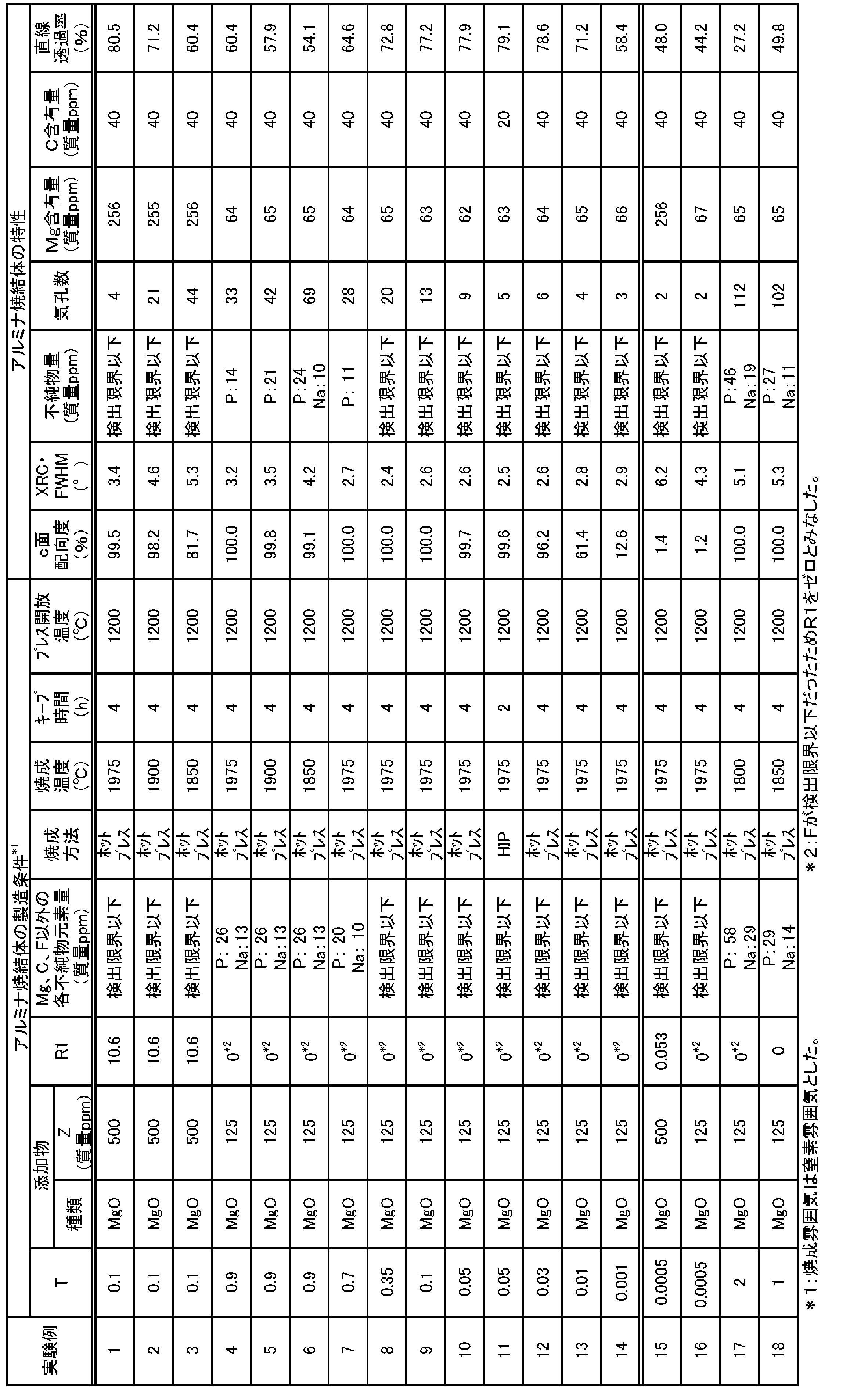
[実験例2,3]
実験例2,3は、焼成温度(最高到達温度)をそれぞれ1900℃,1850℃とした以外は、実験例1と同様にしてアルミナ焼結体を作製した。これらのアルミナ焼結体につき、上記2.(1)~(5)の特性を求めた。その結果を表1に示した。
実験例2,3は、焼成温度(最高到達温度)をそれぞれ1900℃,1850℃とした以外は、実験例1と同様にしてアルミナ焼結体を作製した。これらのアルミナ焼結体につき、上記2.(1)~(5)の特性を求めた。その結果を表1に示した。
[実験例4]
板状アルミナ原料として市販の板状アルミナ粉末(キンセイマテック株式会社製、グレード10030、平均粒径10μm、平均厚み0.3μm、アスペクト比33)を使用し、板状アルミナ粉末と微細なアルミナ粉末(TM-DAR、平均粒径0.1μm、大明化学製)をそれぞれ0.9質量部と99.1質量部で混合した以外は、実験例1と同様の方法でアルミナ焼結体を作製した。なお、板状アルミナ粉末及び混合アルミナ粉末中に含まれるFは検出限界(500質量ppm)以下であったため、質量比R1をゼロとみなした。また、混合アルミナ粉末中のMg、C、F以外の各不純物元素として、Pが26質量ppm、Naが13質量ppm検出された。得られたアルミナ焼結体につき、上記2.(1)~(5)の特性を求めた。その結果を表1に示した。
板状アルミナ原料として市販の板状アルミナ粉末(キンセイマテック株式会社製、グレード10030、平均粒径10μm、平均厚み0.3μm、アスペクト比33)を使用し、板状アルミナ粉末と微細なアルミナ粉末(TM-DAR、平均粒径0.1μm、大明化学製)をそれぞれ0.9質量部と99.1質量部で混合した以外は、実験例1と同様の方法でアルミナ焼結体を作製した。なお、板状アルミナ粉末及び混合アルミナ粉末中に含まれるFは検出限界(500質量ppm)以下であったため、質量比R1をゼロとみなした。また、混合アルミナ粉末中のMg、C、F以外の各不純物元素として、Pが26質量ppm、Naが13質量ppm検出された。得られたアルミナ焼結体につき、上記2.(1)~(5)の特性を求めた。その結果を表1に示した。
[実験例5~14]
実験例5~14は、実験例4と同じ市販の板状アルミナ粉末と微細なアルミナ粉末を用いて表1に示すアルミナ焼結体の製造条件でアルミナ焼結体を作製した。但し、実験例11では、焼成温度1975℃で2時間、面圧1886kgf/cm2の条件でHIP焼成してアルミナ焼結体を得た。HIP焼成においては、1975℃のキープ終了後、1200℃までは面圧1000kgf/cm2以上の高圧を保った状態で降温した。これらの実験例で得られたアルミナ焼結体につき、上記2.(1)~(5)の特性を求めた。その結果を表1に示した。
実験例5~14は、実験例4と同じ市販の板状アルミナ粉末と微細なアルミナ粉末を用いて表1に示すアルミナ焼結体の製造条件でアルミナ焼結体を作製した。但し、実験例11では、焼成温度1975℃で2時間、面圧1886kgf/cm2の条件でHIP焼成してアルミナ焼結体を得た。HIP焼成においては、1975℃のキープ終了後、1200℃までは面圧1000kgf/cm2以上の高圧を保った状態で降温した。これらの実験例で得られたアルミナ焼結体につき、上記2.(1)~(5)の特性を求めた。その結果を表1に示した。
[実験例15]
実験例15はTの値を0.0005とした以外は、実験例1と同様にしてアルミナ焼結体を作製した。得られたアルミナ焼結体につき、上記2.(1)~(5)の特性を求めた。その結果を表1に示した。
実験例15はTの値を0.0005とした以外は、実験例1と同様にしてアルミナ焼結体を作製した。得られたアルミナ焼結体につき、上記2.(1)~(5)の特性を求めた。その結果を表1に示した。
[実験例16~18]
実験例16~18は、実験例4と同じ市販の板状アルミナ粉末と微細なアルミナ粉末を用いて表1に示すアルミナ焼結体の製造条件でアルミナ焼結体を作製した。得られたアルミナ焼結体につき、上記2.(1)~(5)の特性を求めた。その結果を表1に示した。
実験例16~18は、実験例4と同じ市販の板状アルミナ粉末と微細なアルミナ粉末を用いて表1に示すアルミナ焼結体の製造条件でアルミナ焼結体を作製した。得られたアルミナ焼結体につき、上記2.(1)~(5)の特性を求めた。その結果を表1に示した。
[評価]
実験例1~14では、板状アルミナ粉末と微細アルミナ粉末とを含むアルミナ原料粉末を、板状アルミナ粉末と微細アルミナ粉末との混合割合が質量比でT:(100-T)(T=0.001~0.9)、質量比R1が15ppm未満となるように調製し、そのアルミナ原料粉末を含む成形用原料を成形したあと焼成した。実験例1~14で得られたアルミナ焼結体は、配向度が高く、緻密で高純度であり、直線透過率の高い(つまり透明性の高い)ものとなった。また、この製法では、従来のように高磁場を利用する必要がなく、フッ素化合物の処理装置も必要がないため、透明アルミナ焼結体の製造コストを低く抑えることができる。更に、透明アルミナ焼結体を容易に製造できるため、大量生産に向いている。
実験例1~14では、板状アルミナ粉末と微細アルミナ粉末とを含むアルミナ原料粉末を、板状アルミナ粉末と微細アルミナ粉末との混合割合が質量比でT:(100-T)(T=0.001~0.9)、質量比R1が15ppm未満となるように調製し、そのアルミナ原料粉末を含む成形用原料を成形したあと焼成した。実験例1~14で得られたアルミナ焼結体は、配向度が高く、緻密で高純度であり、直線透過率の高い(つまり透明性の高い)ものとなった。また、この製法では、従来のように高磁場を利用する必要がなく、フッ素化合物の処理装置も必要がないため、透明アルミナ焼結体の製造コストを低く抑えることができる。更に、透明アルミナ焼結体を容易に製造できるため、大量生産に向いている。
一方、実験例15,16では、Tが0.0005と小さすぎたため、c面配向度が小さすぎたりチルト角(XRC・FWHM)が大きすぎたりして直線透過率の低いアルミナ焼結体しか得られなかった。実験例17では、Tが2と大きすぎたため、気孔数が多くなりすぎ、直線透過率の低いアルミナ焼結体しか得られなかった。実験例18では、Tが1と大きすぎたため、気孔数が多くなりすぎ、直線透過率の低いアルミナ焼結体しか得られなかった。
なお、実験例1~14が本発明の実施例に相当し、実験例15~18が比較例に相当する。本発明は、上述した実験例に何ら限定されることはなく、本発明の技術的範囲に属する限り種々の態様で実施し得ることはいうまでもない。
本出願は、2015年9月30日に出願された日本国特許出願第2015-193944号を優先権主張の基礎としており、引用によりその内容の全てが本明細書に含まれる。
本発明は、光学素子や光学素子用下地基板、エピタキシャル成長用基板、静電チャックなどに利用可能である。
Claims (6)
- (a)アスペクト比が3以上の板状アルミナ粉末と、前記板状アルミナ粉末よりも平均粒径が小さな微細アルミナ粉末とを含むアルミナ原料粉末を、前記板状アルミナ粉末と前記微細アルミナ粉末との混合割合が質量比でT:(100-T)としたときにTが0.001以上、1未満となるよう調製し、且つ該アルミナ原料粉末中のFのAlに対する質量比R1が15ppm未満となるように調製する工程と、
(b)前記アルミナ原料粉末を含む成形用原料を成形して成形体にする工程と、
(c)前記成形体を焼成することにより透明アルミナ焼結体を得る工程と、
を含む透明アルミナ焼結体の製法。
但し、質量比R1は、下記式(1)で算出される値であり、単位は質量ppmである。前記アルミナ原料粉末に添加物を外配で添加する場合、前記アルミナ原料粉末に対する前記添加物の割合をZ(質量%)とする。x1は、前記板状アルミナ粉末中のF含有率(質量ppm)、x2は、前記微細アルミナ粉末中のF含有率(質量ppm)、x3は前記添加物中のF含有率(質量ppm)である。F含有量は、アルカリ融解-イオンクロマトグラフ法で求める。y1は、前記板状アルミナ粉末中のAl含有率(質量%)、y2は、前記微細アルミナ粉末中のAl含有率(質量%)である。前記Al含有率は、各アルミナ粉末のアルミナ純度を100-(Al,O以外の不純物元素の質量%の和)として求め、それに0.529を乗じた値(質量%)とする。前記不純物元素の質量%は、以下のように定量する。すなわち、Sは燃焼(高周波加熱)-赤外線吸収法、Nは不活性ガス融解-熱伝導度法、Hは不活性ガス融解-非分散型赤外線吸収法、Fはアルカリ融解-イオンクロマトグラフ法、その他の元素はICP(誘導結合プラズマ)発光分析で定量する。y3は、前記添加物中のAl含有率(質量%)であり、ICP(誘導結合プラズマ)発光分析で定量する。
R1=100×[x1×T+x2×(100-T)+x3×Z]/[y1×T+y2×(100-T)+y3 ×Z}…(1) - 前記工程(b)では、前記成形用原料として、前記アルミナ原料粉末100質量部に対して、MgOを0.005~0.5質量部添加したものを用いる、
請求項1に記載の透明アルミナ焼結体の製法。 - 前記工程(c)では、前記透明アルミナ焼結体に含まれるMg、C以外の各不純物元素が10質量ppm以下となるように焼成する、
請求項1又は2に記載の透明アルミナ焼結体の製法。 - 前記工程(c)では、前記成形体を1850℃以上で焼成する、
請求項1~3のいずれか1項に記載の透明アルミナ焼結体の製法。 - 前記工程(c)では、前記成形体を加圧焼成する、
請求項1~4のいずれか1項に記載の透明アルミナ焼結体の製法。 - 前記工程(c)では、焼成中の最高到達温度からの降温時において、1000~1400℃の範囲で設定された所定温度まで50kgf/cm2以上の圧力を印加し続け、前記所定温度以下の温度域では50kgf/cm2未満まで除圧する、
請求項5に記載の透明アルミナ焼結体の製法。
Priority Applications (2)
| Application Number | Priority Date | Filing Date | Title |
|---|---|---|---|
| JP2017543546A JP6649959B2 (ja) | 2015-09-30 | 2016-09-29 | 透明アルミナ焼結体の製法 |
| US15/903,146 US10717677B2 (en) | 2015-09-30 | 2018-02-23 | Method for producing transparent alumina sintered body |
Applications Claiming Priority (2)
| Application Number | Priority Date | Filing Date | Title |
|---|---|---|---|
| JP2015193944 | 2015-09-30 | ||
| JP2015-193944 | 2015-09-30 |
Related Child Applications (1)
| Application Number | Title | Priority Date | Filing Date |
|---|---|---|---|
| US15/903,146 Continuation US10717677B2 (en) | 2015-09-30 | 2018-02-23 | Method for producing transparent alumina sintered body |
Publications (1)
| Publication Number | Publication Date |
|---|---|
| WO2017057552A1 true WO2017057552A1 (ja) | 2017-04-06 |
Family
ID=58427643
Family Applications (1)
| Application Number | Title | Priority Date | Filing Date |
|---|---|---|---|
| PCT/JP2016/078789 Ceased WO2017057552A1 (ja) | 2015-09-30 | 2016-09-29 | 透明アルミナ焼結体の製法 |
Country Status (4)
| Country | Link |
|---|---|
| US (1) | US10717677B2 (ja) |
| JP (1) | JP6649959B2 (ja) |
| TW (1) | TWI705951B (ja) |
| WO (1) | WO2017057552A1 (ja) |
Cited By (2)
| Publication number | Priority date | Publication date | Assignee | Title |
|---|---|---|---|---|
| JP2019006648A (ja) * | 2017-06-27 | 2019-01-17 | 日本碍子株式会社 | 配向セラミックス焼結体及びその製法 |
| CN111164060A (zh) * | 2017-08-01 | 2020-05-15 | 飞罗得材料技术股份有限公司 | 氧化铝烧结体及其制造方法、以及半导体制造装置用部件 |
Families Citing this family (4)
| Publication number | Priority date | Publication date | Assignee | Title |
|---|---|---|---|---|
| US11760694B2 (en) | 2017-10-05 | 2023-09-19 | Coorstek Kk | Alumina sintered body and manufacturing method therefor |
| JP7066585B2 (ja) * | 2018-09-19 | 2022-05-13 | キオクシア株式会社 | 記憶装置 |
| US12076886B2 (en) * | 2020-03-02 | 2024-09-03 | Purdue Research Foundation | Transparent alumina-based plate and method of making thereof |
| CN112110740B (zh) * | 2020-09-27 | 2022-11-25 | 景德镇陶瓷大学 | 一种原位反应制备氧化铝基复合生物陶瓷材料的方法及其制得的产品 |
Citations (3)
| Publication number | Priority date | Publication date | Assignee | Title |
|---|---|---|---|---|
| JPS5130209A (ja) * | 1974-09-06 | 1976-03-15 | Matsushita Electric Industrial Co Ltd | |
| JP2000219570A (ja) * | 1999-01-29 | 2000-08-08 | Sumitomo Chem Co Ltd | 透光性アルミナ焼結体の製造方法およびその用途 |
| JP2002293609A (ja) * | 2001-03-29 | 2002-10-09 | Ngk Insulators Ltd | セラミックス多結晶体及びその製造方法 |
Family Cites Families (5)
| Publication number | Priority date | Publication date | Assignee | Title |
|---|---|---|---|---|
| JP2004359495A (ja) * | 2003-06-04 | 2004-12-24 | Ngk Insulators Ltd | エピタキシャル膜用アルミナ基板 |
| JP4357584B1 (ja) | 2008-10-01 | 2009-11-04 | 株式会社ニッカトー | 耐食性、耐熱衝撃抵抗性及び耐久性に優れたアルミナ質焼結体 |
| JP5396176B2 (ja) | 2008-10-09 | 2014-01-22 | 日本碍子株式会社 | ウエハ載置台及びその製法 |
| JP5501040B2 (ja) | 2009-03-26 | 2014-05-21 | 日本碍子株式会社 | アルミナ焼結体、その製法及び半導体製造装置部材 |
| JP6621422B2 (ja) * | 2014-11-28 | 2019-12-18 | 日本碍子株式会社 | 透明アルミナ焼結体の製法 |
-
2016
- 2016-09-29 JP JP2017543546A patent/JP6649959B2/ja active Active
- 2016-09-29 WO PCT/JP2016/078789 patent/WO2017057552A1/ja not_active Ceased
- 2016-09-29 TW TW105131224A patent/TWI705951B/zh not_active IP Right Cessation
-
2018
- 2018-02-23 US US15/903,146 patent/US10717677B2/en active Active
Patent Citations (3)
| Publication number | Priority date | Publication date | Assignee | Title |
|---|---|---|---|---|
| JPS5130209A (ja) * | 1974-09-06 | 1976-03-15 | Matsushita Electric Industrial Co Ltd | |
| JP2000219570A (ja) * | 1999-01-29 | 2000-08-08 | Sumitomo Chem Co Ltd | 透光性アルミナ焼結体の製造方法およびその用途 |
| JP2002293609A (ja) * | 2001-03-29 | 2002-10-09 | Ngk Insulators Ltd | セラミックス多結晶体及びその製造方法 |
Non-Patent Citations (1)
| Title |
|---|
| CHANG, YUNFEI ET AL.: "Fabrication of Highly Textured Fine-Grained a-Alumina by Templated Grain Growth of Nanoscale Precursors", JOURNAL OF THE AMERICAN CERAMIC SOCIETY, vol. 96, no. 5, 2013, pages 1390 - 1397 * |
Cited By (2)
| Publication number | Priority date | Publication date | Assignee | Title |
|---|---|---|---|---|
| JP2019006648A (ja) * | 2017-06-27 | 2019-01-17 | 日本碍子株式会社 | 配向セラミックス焼結体及びその製法 |
| CN111164060A (zh) * | 2017-08-01 | 2020-05-15 | 飞罗得材料技术股份有限公司 | 氧化铝烧结体及其制造方法、以及半导体制造装置用部件 |
Also Published As
| Publication number | Publication date |
|---|---|
| TW201730134A (zh) | 2017-09-01 |
| JPWO2017057552A1 (ja) | 2018-07-19 |
| US20180244579A1 (en) | 2018-08-30 |
| TWI705951B (zh) | 2020-10-01 |
| US10717677B2 (en) | 2020-07-21 |
| JP6649959B2 (ja) | 2020-02-19 |
Similar Documents
| Publication | Publication Date | Title |
|---|---|---|
| JP6585620B2 (ja) | アルミナ焼結体及び光学素子用下地基板 | |
| JP6621422B2 (ja) | 透明アルミナ焼結体の製法 | |
| JP6649959B2 (ja) | 透明アルミナ焼結体の製法 | |
| JP6691133B2 (ja) | アルミナ焼結体及び光学素子用下地基板 | |
| JP6626500B2 (ja) | アルミナ焼結体及び光学素子用下地基板 | |
| US11014855B2 (en) | Transparent AlN sintered body and method for producing the same |
Legal Events
| Date | Code | Title | Description |
|---|---|---|---|
| 121 | Ep: the epo has been informed by wipo that ep was designated in this application |
Ref document number: 16851723 Country of ref document: EP Kind code of ref document: A1 |
|
| ENP | Entry into the national phase |
Ref document number: 2017543546 Country of ref document: JP Kind code of ref document: A |
|
| NENP | Non-entry into the national phase |
Ref country code: DE |
|
| 122 | Ep: pct application non-entry in european phase |
Ref document number: 16851723 Country of ref document: EP Kind code of ref document: A1 |