WO2017056627A1 - Procédé d'analyse de rigidité de carrosserie de véhicule - Google Patents
Procédé d'analyse de rigidité de carrosserie de véhicule Download PDFInfo
- Publication number
- WO2017056627A1 WO2017056627A1 PCT/JP2016/070406 JP2016070406W WO2017056627A1 WO 2017056627 A1 WO2017056627 A1 WO 2017056627A1 JP 2016070406 W JP2016070406 W JP 2016070406W WO 2017056627 A1 WO2017056627 A1 WO 2017056627A1
- Authority
- WO
- WIPO (PCT)
- Prior art keywords
- vehicle body
- mass
- skeleton model
- lid
- rigidity
- Prior art date
Links
Images


Classifications
-
- G—PHYSICS
- G06—COMPUTING; CALCULATING OR COUNTING
- G06F—ELECTRIC DIGITAL DATA PROCESSING
- G06F30/00—Computer-aided design [CAD]
- G06F30/10—Geometric CAD
- G06F30/15—Vehicle, aircraft or watercraft design
-
- G—PHYSICS
- G01—MEASURING; TESTING
- G01M—TESTING STATIC OR DYNAMIC BALANCE OF MACHINES OR STRUCTURES; TESTING OF STRUCTURES OR APPARATUS, NOT OTHERWISE PROVIDED FOR
- G01M17/00—Testing of vehicles
- G01M17/007—Wheeled or endless-tracked vehicles
-
- G—PHYSICS
- G06—COMPUTING; CALCULATING OR COUNTING
- G06F—ELECTRIC DIGITAL DATA PROCESSING
- G06F30/00—Computer-aided design [CAD]
Definitions
- the present invention relates to a stiffness analysis method for an automobile body, and more particularly to a vehicle skeleton (inertia force) that takes into account the influence of inertia force acting in the driving condition of an automobile.
- the present invention relates to a vehicle body stiffness analysis method for performing a stiffness analysis of an automotive body structure.
- Patent Literature 1 discloses a support for stiffness evaluation method for evaluating the rigidity of a vehicle in a running state by numerical analysis.
- the fitting is a general term for an engine, a transmission, a seat, and the like
- the lid is a door, a trunk, a hood, and the like.
- the vehicle stiffness evaluation support method disclosed in Patent Document 1 evaluates the vehicle stiffness in a freely supported state in which the vehicle body is supported by an absorber or a soft bush.
- the vehicle is provided with fittings and lids.
- CAE analysis is performed on the vehicle (full body) with the fittings and lids to evaluate the performance of the body frame. Even so, there is no time to go back and modify the body frame design. Therefore, conventionally, there has been no choice but to perform performance evaluation and design of the vehicle body skeleton by CAE analysis only for the vehicle skeleton.
- the present invention has been made in order to solve the above-described problems, and in a vehicle body skeleton model, these fittings or lids can be substituted for these fittings or lids even before the fittings or lids are determined. It is an object of the present invention to provide a vehicle body rigidity analysis method capable of performing a rigidity analysis with high accuracy in consideration of an inertial force acting when a vehicle is running.
- a vehicle body rigidity analysis method has a fixed connecting part for fixing or connecting a fitting or a lid, and includes a plane element or a three-dimensional element (A vehicle body stiffness analysis method in which a computer performs a stiffness analysis using an automobile body skeleton model configured using at least one of solid elements), and a fitting or a lid is attached to a fixed connection portion of the body skeleton model.
- a mass setting body skeleton model generating step for generating a mass setting body skeleton model by setting a mass corresponding to the mass of the fitting or lid at a predetermined position in a fixed or connected region; and the mass setting body skeleton model And a rigidity analysis step for performing a rigidity analysis in consideration of an inertial force acting when the automobile is running.
- the vehicle body stiffness analysis method according to the present invention is characterized in that, in the above invention, the predetermined position in the mass setting vehicle body skeleton model generation step is set on a straight line or a curve connecting the fixed connecting portions.
- the predetermined position is set to a rotationally movable center when the fitting or the lid is rotationally movable. It is characterized by being set to a position excluding the axis.
- the vehicle body rigidity analysis method according to the present invention is the vehicle body rigidity analysis method according to the above invention, wherein the predetermined position in the mass setting vehicle body skeleton model generation step is surrounded by a straight line connecting the fixed connection portions, except on the straight line. Or it sets on the curved surface except the line of the said curve enclosed by the curve which connects the said fixed connection part, It is characterized by the above-mentioned.
- the mass setting vehicle body skeleton model generation step includes a mass element, a mass element, and a mass element corresponding to a mass of the fitting or the lid. It sets using the rigid body element which connects the said fixed connection part, It is characterized by the above-mentioned.
- the mass setting vehicle body skeleton model generation step uses a mass element and a beam element as a mass corresponding to a mass of the fitting or the lid.
- the sum of the mass of the mass element and the beam element that is set corresponds to the mass of the fitting or lid fixed or connected to the fixed connection part.
- the mass setting vehicle body skeleton model generation step includes a mass corresponding to a mass of the fitting or the lid, and a mass corresponding to a mass of the fitting or the lid. It is characterized by setting using a beam element.
- the present invention has a fixed connecting portion for fixing or connecting a fitting or a lid, and the vehicle body skeleton model is configured by using at least one of a planar element and a three-dimensional element.
- a mass setting vehicle skeleton model generating step for generating a mass setting vehicle skeleton model by setting a mass corresponding to the mass of the fitting or lid at a predetermined position in a region fixed or connected to the fixed connecting portion;
- the model includes a stiffness analysis step that performs a stiffness analysis in consideration of the inertial force that is applied when the vehicle is running, thereby taking into account the inertial force that is applied to the fitting or the lid when the vehicle is running. Can be evaluated.
- FIG. 1 is a flowchart showing a process flow of a vehicle body rigidity analysis method according to an embodiment of the present invention.
- FIG. 2 is an explanatory diagram for explaining a vehicle body skeleton model used in the vehicle body rigidity analysis method according to the embodiment of the present invention.
- FIG. 3 is an explanatory diagram for explaining a mass setting vehicle body skeleton model to be analyzed by the vehicle body rigidity analysis method according to the embodiment of the present invention.
- FIG. 4 is a block diagram showing the configuration of a stiffness analysis apparatus that implements the vehicle body stiffness analysis method according to the embodiment of the present invention.
- FIG. 1 is a flowchart showing a process flow of a vehicle body rigidity analysis method according to an embodiment of the present invention.
- FIG. 2 is an explanatory diagram for explaining a vehicle body skeleton model used in the vehicle body rigidity analysis method according to the embodiment of the present invention.
- FIG. 3 is an explanatory diagram for explaining a mass setting vehicle body skeleton model to be analyzed
- FIG. 5 is an explanatory diagram illustrating a predetermined position where the mass is set in the mass setting vehicle body skeleton model generation step of the vehicle body rigidity analysis method according to the embodiment of the present invention.
- FIG. 6 is an explanatory diagram for explaining the mass setting vehicle skeleton model in which the mass is set in the mass setting vehicle skeleton model generation step of the vehicle body rigidity analysis method according to the embodiment of the present invention.
- FIG. 7 is an explanatory diagram for explaining a mass setting method in the mass setting vehicle body skeleton model generation step of the vehicle body rigidity analysis method according to the embodiment of the present invention.
- FIG. 8 is an explanatory diagram for explaining the load constraint conditions in the rigidity analysis of the static torsion of the vehicle body in the embodiment of the present invention.
- FIG. 9 is a diagram showing a result of displacement in the load direction obtained by rigidity analysis of the static torsion of the vehicle body in the example of the present invention.
- FIG. 10 is a diagram showing the results of the average torsional stiffness and the rate of change of stiffness (changing rate of stiffness) of the inventive example and the comparative example obtained by the rigidity analysis of the static torsion of the vehicle body in the example of the present invention.
- FIG. 11 is an explanatory diagram for explaining a load condition (load condition) assuming a lane change in the embodiment of the present invention.
- FIG. 12 is a diagram showing the results of load point displacement and stiffness change rate in stiffness analysis assuming a lane change in the embodiment of the present invention.
- FIG. 13 is a diagram for explaining a load condition applied to the front side of the vehicle body in the embodiment of the present invention.
- FIG. 14 is a diagram showing a result of displacement in the load direction under each load condition applied to the front side of the vehicle body in the example of the present invention.
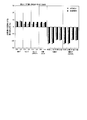
- FIG. 15 is a diagram showing the result of the rate of change in rigidity under each load condition applied to the front side of the vehicle body in the example of the present invention.
- FIG. 16 is a diagram showing the correlation between the stiffness value and the stiffness change rate between the example of the present invention and the comparative example 2 under each load condition given to the front side of the vehicle body in the example of the present invention.
- FIG. 17 is a diagram illustrating a load condition applied to the rear side of the vehicle body (rear side of automotive body) in the embodiment of the present invention.
- FIG. 18 is a diagram showing a result of displacement in the load direction under each load condition given to the rear side of the vehicle body in the example of the present invention.
- FIG. 19 is a diagram showing the result of the rate of change in rigidity under each load condition applied to the rear side of the vehicle body in the example of the present invention.
- FIG. 20 is a diagram showing the correlation between the stiffness value and the stiffness change rate between the example of the present invention and the comparative example 2 under each load condition applied to the rear side of the vehicle body in the example of the present invention.
- the vehicle body rigidity analysis method according to the present embodiment includes a fixed connection portion 3 for fixing or connecting a fitting or a lid, and a vehicle body skeleton model 1 configured using at least one of a planar element and a three-dimensional element.
- the stiffness analysis is performed with the mass setting vehicle body skeleton model 21 (see FIG. 3) generated by setting the mass corresponding to the fitting or the lid as an analysis target.
- the vehicle body rigidity analysis method according to the present embodiment can be performed using a vehicle body rigidity analysis device 41 (hereinafter simply referred to as a “rigidity analysis device”) configured as shown in the block diagram of FIG.
- a vehicle body rigidity analysis device 41 hereinafter simply referred to as a “rigidity analysis device” configured as shown in the block diagram of FIG.
- the vehicle body skeleton model 1 used in the present invention is composed only of skeleton parts such as a chassis, and has a fixed connecting portion 3 for fixing or connecting a fitting or a lid. .
- the vehicle body skeleton model 1 is configured using at least one of a planar element and a three-dimensional element, and element information thereof is stored in a vehicle body skeleton model file 60 (see FIG. 4).
- the fixed linking part 3 included in the vehicle body skeleton model 1 includes an upper hinge 3 a that fixes or connects a revolving door, a lower hinge 3 b, a striker (striker). ) 3c and the like.
- the fixed connecting portion 3 is not limited to these, and is used for fixing fittings such as an engine mount for fixing an engine, a slide door other than a revolving door, and a bonnet.
- Etc. are also included for fixing or connecting the lid.
- a stiffness analysis device 41 used in the vehicle body stiffness analysis method according to the present embodiment is a device that performs stiffness analysis using the mass setting vehicle body skeleton model 21 shown in FIG. 3 as an analysis target, and is a personal computer (PC). computer)).
- the stiffness analyzer 41 includes a display device 43, an input device 45, a storage device 47, a working data memory 49, and an arithmetic process. Part (arithmetic processing unit) 50.
- a display device 43, an input device 45, a storage device 47, and a work data memory 49 are connected to the arithmetic processing unit 50, and each function is executed according to instructions from the arithmetic processing unit 50.
- the display device 43 is used for displaying calculation results, and is composed of a liquid crystal monitor (LCD monitor) or the like.
- the input device 45 is used for an instruction to display the vehicle body skeleton model 1 and the mass setting vehicle body skeleton model 21 by the operator, input of analysis conditions, and the like, and includes a keyboard, a mouse, and the like.
- the storage device 47 is used for storing a file, and is composed of a hard disk or the like.
- the storage device 47 stores at least various files such as the vehicle body skeleton model file 60, a program executed by the arithmetic processing unit 50, and the like.
- the work data memory 49 is used for temporary storage and calculation of data used in the arithmetic processing unit 50, and includes a RAM (random access memory) or the like.
- the arithmetic processing unit 50 includes a CPU (central processing unit) such as a PC, and includes a mass setting vehicle body skeleton model generation unit 51 and a stiffness analysis unit 53. Each of the above units is realized by the CPU executing a predetermined program.
- CPU central processing unit
- the arithmetic processing part 50 is demonstrated in detail based on FIG.
- the mass setting body skeleton model generation unit 51 sets a mass corresponding to the mass of the equipment or lid at a predetermined position in a region where the equipment or lid is fixed or connected to the fixed connection unit 3 of the body skeleton model 1. Thus, the mass setting vehicle body skeleton model 21 is generated.
- the stiffness analysis unit 53 analyzes the stiffness of the mass setting vehicle body skeleton model 21 generated by setting the mass of the vehicle body skeleton model 1 by the mass setting vehicle body skeleton model generation unit 51 in consideration of the inertial force acting when the vehicle is running. Is to do.
- the vehicle body stiffness analysis method includes a mass setting vehicle body skeleton model generation step S1 for setting a mass corresponding to a fitting or a lid in the vehicle body skeleton model 1, A stiffness analysis step S3 for performing a stiffness analysis in consideration of the acting inertial force.
- a mass setting vehicle body skeleton model generation step S1 for setting a mass corresponding to a fitting or a lid in the vehicle body skeleton model 1
- a stiffness analysis step S3 for performing a stiffness analysis in consideration of the acting inertial force.
- each step will be described. Note that each step is executed by a computer in accordance with an instruction from an operator.
- Mass setting body frame model generation step S1 In the mass setting vehicle body skeleton model generation step S1, a mass corresponding to the mass of the equipment or lid is set at a predetermined position in a region where the equipment or lid is fixed or connected to the fixed connection portion 3 of the vehicle body skeleton model 1. Thus, the mass setting vehicle body skeleton model 21 is generated.
- This mass setting vehicle body skeleton model generation step S1 is performed by the mass setting vehicle body skeleton model generation unit 51 of the stiffness analyzer 41.
- the mass element 11 is set at a predetermined position in a region where the fitting or the lid is fixed or connected, which corresponds to the mass of the fitting or the lid.
- the mass to be set can be set.
- the predetermined position for setting the mass element 11 is, as shown in FIG. 5, on a straight line L that connects a plurality of fixed connection portions 3 (hinge 3a and striker 3c, hinge 3b and striker 3c, hinge 3a and hinge 3b) ( 5 (a)), or on a curve connecting the fixed connecting portions 3 along the shape of the vehicle body on which a lid or the like is mounted.
- the rotational movement is possible when the revolving door is rotationally movable on a line connecting the hinge 3a and the hinge 3b of the revolving door.
- the rotationally movable central axis is substantially at the same position as the boundary of the region where the revolving door is fixed or connected to the vehicle body skeleton model 1.
- the straight line connecting the hinge 3a and the striker 3c of the revolving door and the straight line connecting the hinge 3b and the striker 3c are located inside the region where the revolving door is fixed or connected to the vehicle body skeleton model 1.
- the predetermined position for setting the mass corresponding to the fitting or the lid is the rotation movable central axis when the fitting or the lid is rotationally movable on the straight line L or the curved line connecting the plurality of fixed connecting portions 3. It is desirable to set the position excluding the top.
- the predetermined position for setting the mass corresponding to the fitting or the lid is not limited to the straight line L or the curved line, but on the plane P surrounded by the straight line L (see FIG. 5B). Alternatively, it may be set on a curved surface (not shown) surrounded by a curve.
- the straight line L or the curve is the boundary of the plane P or the curved surface, it is desirable to set the mass corresponding to the fitting or the lid inside the boundary. Therefore, the predetermined position for setting the mass corresponding to the fitting or the lid is set on the plane P surrounded by the straight line L (except on the straight line L), or on the curved surface surrounded by the curve ( However, it is more preferable to set to (except on the curved line).
- the fixed connection parts 3 are connected by a straight line so that the two straight lines intersect each other, and the mass element 11 is set on the straight line. It is preferable.
- the fixed connecting portion 3 may be connected by a curve in accordance with the curvature of the vehicle body, and the mass element 11 may be set on the curve.
- specific mass setting methods for setting the mass at the predetermined position described above include, for example, the following (1), (2), and (3).
- a mass element 11 having a mass corresponding to the mass of a fitting or a lid is set at a predetermined position, and the mass element 11 and the fixed connecting portion 3 are connected using a rigid element 15 (FIG. 6A).
- FIG. 6 (a) is an example in which one mass element 11 is set on the center of the straight line L connecting the fixed connecting portions 3. As shown in FIG. 6 (b), the straight line L is evenly distributed.
- a plurality of mass elements 11 may be set on the points to be divided. When a plurality of mass elements 11 are set in this way, the mass of each mass element 11 may be determined so that the sum of the mass of each mass element 11 corresponds to the mass of the fitting or the lid.
- the mass element 11 having a mass corresponding to the mass of the fitting or lid is set at a predetermined position, and the mass element 11 and the fixed coupling portion 3 are connected using the beam element 17 (see FIG. 7A). ).
- the sum of the masses of the mass element 11 and the beam element 17 is set so as to correspond to the mass of the fitting or lid fixed or coupled to the fixed coupling portion 3.
- the mass of the beam element 17 is determined by the cross-sectional area given as the cross-sectional property of the beam element 17 and the material density given as the material property. It is done.
- the cross-sectional area of the beam element 17 is determined, for example, by giving the radius of the beam element 17.
- the cross-sectional characteristics and material characteristics necessary for transmitting the load due to the inertial force acting on the mass element 11 and the beam element 17 to the mass setting vehicle body skeleton model 21 are given to the beam element 17. It is necessary to set appropriately.
- the beam element 17 is a linear element, and rod elements can be used as long as they can transmit a tensile load and a compressive load acting in the axial direction of the element. (Bar element) may be used. Similar to the beam element 17, the mass of the rod element is determined by the cross-sectional area (or radius) given as a cross-sectional characteristic and the material density given as a material characteristic.
- the mass of the beam element 17 is determined by the cross-sectional area given as the cross-sectional characteristic of the beam element 17 and the material density given as the material characteristic.
- the cross-sectional area of the beam element 17 is determined by giving the radius of the beam element 17, for example.
- the inertial force acting when the vehicle is running is considered for the mass setting body skeleton model 21 or the mass setting body skeleton model 23 (see FIG. 6) in which the mass is set in the mass setting body skeleton model generation step S1.
- This is the step of performing rigidity analysis.
- a load condition load constraint condition
- the inertial force acting when the vehicle is running is taken into account using an inertia relief method.
- the inertia relief method is based on a force acting on an object in a uniform-accelerated motion in a state where the object is supported by a support point serving as a reference of inertial force coordinates (free support state).
- This is an analysis method for obtaining stress and strain, and is used for static analysis of a moving airplane or ship (see Patent Document 1).
- a mass corresponding to the rotating door component is set at a predetermined position in a region where the rotating door component as a lid is fixed or connected to the fixed connecting portion 3 of the vehicle body skeleton model 1 shown in FIG.
- Rigidity analysis was performed using the set mass-set vehicle body skeleton model as an analysis target.
- the mass of the vehicle body skeleton model 1 is about 300 kg, and the mass of the rotating door components set in the vehicle body skeleton model 1 is 10 kg per piece. Therefore, as an example of the invention, ten mass elements 11 are evenly arranged on a straight line connecting the upper hinge 3a and the striker 3c in the vehicle body skeleton model 1, and the mass element 11, the hinge 3a, and the striker 3c are rigid elements 15
- FIG. 8 shows load constraint conditions.
- the constraint point was a front suspension mounting position of the vehicle body (see B in FIG. 8) and a rear suspension mounting position of the vehicle body (see C and D in FIG. 8).
- the rigidity in static torsion was evaluated based on the average torsional rigidity determined as follows. First, a load is applied to the load point (see A in FIG. 8) based on the straight line connecting the sub-frame attachment positions (see C and D in FIG. 8) of the rear side of the vehicle body (angle 0 degree). The average inclination angle is obtained by averaging the inclination angle of the vehicle body viewed from the front side of the vehicle body over the longitudinal direction of the vehicle body. Then, the average torsional rigidity is obtained by dividing the load applied to the load point by the average inclination angle.
- FIG. 9 the result of the displacement of the load direction of the mass setting vehicle body frame
- FIG. 10 shows the average torsional rigidity and the rigidity change rate obtained from the displacement obtained from the result of the rigidity analysis.
- the rigidity change rate is a relative change in the average torsional rigidity obtained based on the rigidity of the vehicle body skeleton model 1 (see Comparative Example 1).
- the rigidity change rate in the present invention example can be obtained by, for example, the following formula (1).
- Rigidity change rate (%) (average torsional rigidity of the present invention example ⁇ average torsional rigidity of comparative example 1) / average torsional rigidity of comparative example ⁇ 100 (1)
- both the inventive example and the comparative example 2 resulted in the same average torsional rigidity as the comparative example 1 in which the vehicle body skeleton model 1 was analyzed, and the stiffness change rate was also slight.
- a rigidity analysis was performed assuming an automobile in a running state, and the influence of inertial force on the rigidity of the vehicle body was verified.
- the vehicle in a running state is lane-changed, as shown in FIG. 11, four load points are set at the subframe mounting position on the rear side of the vehicle body (“RH” in FIG. 11).
- RH subframe mounting position on the rear side of the vehicle body
- a rigidity analysis was performed by applying a load of 1000 N in the vehicle width direction at each load point, and a value obtained by dividing the load by the displacement at each load point was obtained as the rigidity of the vehicle body.
- FIG. 12 shows the results of displacement and rigidity change rate in the present invention example, comparative example 1 and comparative example 2.
- the stiffness change rate was obtained on the basis of the stiffness (Comparative Example 1) obtained by analyzing the vehicle body skeleton model 1 as the analysis target, similarly to the stiffness change rate in the static torsion.
- an inertial force acts on the mass element 11 having a mass corresponding to the mass of the rotating door component, and the inertial force is transmitted to the mass setting vehicle body skeleton model 23 via the rigid body element 15. . Therefore, the displacement of the example of the present invention is about 30% larger than that of Comparative Example 1 in which the rotating door components are not considered (see FIG. 12A), and as a result, the rigidity is reduced by about 20% (FIG. 12). (See (b)). Furthermore, the example of this invention has shown the result which corresponds in general with the displacement and rigidity change rate of the comparative example 2 which considered the revolving door component model as it is. Therefore, it turns out that the result of the example of the present invention is appropriate.
- the vehicle body rigidity analysis method according to the present invention is applied to load conditions corresponding to various driving states of the automobile.
- a load is applied to the front side or rear side of the vehicle body, and the mass corresponding to the mass of the rotating door component is set in the same manner as the rigidity analysis assuming the static torsion and the lane change (example of the present invention).
- FIG. 13 shows a load condition in which a load is applied to the front side of the vehicle body.
- the front bending bending at two mounting position of front suspension (referred to as “front-bending”)
- FIG. 13 (a) is the front suspension mounting position on the right and left sides of the vehicle body (“RH” in FIG. 13 (a)).
- RH front-bending
- LH vertical upward load
- FIG. 13 (b) the front torsion (torsion at two mounting position of front suspension (referred to as “front-torsion”)
- front-torsion is the position of the front suspension mounting positions on the right and left sides of the vehicle body (FIG. 13 (b)).
- One of “RH” and “LH”) is given a vertical upward load, and the other is given a vertical downward load.
- the front single wheel torsion (torsion at one mounting position of front suspension (referred to as “one-side front-torsion”)) shown in FIG. 13 (c) is the right and left front suspension mounting positions (FIG. 13 ( c) (refer to “RH” or “LH”), and a vertical upward load is applied.
- the front lateral bending (lateral bending at two mounting position of front suspension (referred to as “front lateral bending”)) shown in FIG. 13 (d) is the subframe mounting position on the front side of the vehicle body (FIG. 13 (d)). (Refer to “before RH”, “before LH”, “after RH”, and “after LH”) in the vehicle width direction leftward or rightward.
- FIG. 14 shows the results of displacement in the load direction obtained by the rigidity analysis in the present invention example
- FIG. 15 shows the rigidity change rates of the present invention example and the comparative example 2.
- “Bending” and “lateral bending” shown on the horizontal axis in FIG. 15 correspond to the load conditions shown in FIG. 13 (a) and FIG. 13 (d), respectively.
- These rigidity change rates are obtained by dividing the difference between the rigidity obtained by dividing the displacement at each load point by the load at each load point and the rigidity of Comparative Example 1 by the rigidity of Comparative Example 1, thereby comparing Comparative Example 1. It was calculated
- “twist” and “single-wheel torsion” shown on the horizontal axis in FIG. 15 correspond to the load conditions shown in FIGS. 13 (b) and 13 (c), respectively, and the rigidity change under each load condition
- the rate was calculated as follows. First, when a load is applied to a load point (at least one of “RH” or “LH” in FIG. 13) with reference to a straight line connecting the subframe attachment positions on the rear side of the vehicle body (angle 0 degree), The average inclination angle is obtained by averaging the inclination angle of the vehicle body viewed from the side over the longitudinal direction of the vehicle body. Then, the average torsional rigidity is obtained by dividing the load applied to the load point by the average inclination angle. Further, by dividing the difference between the average torsional rigidity and the average torsional rigidity of Comparative Example 1 by the average torsional rigidity of Comparative Example 1, the stiffness change rate is obtained based on the average torsional rigidity in Comparative Example 1.
- “twist (reverse direction)” shown on the horizontal axis in FIG. 15 is a load in the direction opposite to the load direction given to the load points (see “RH” and “LH”) shown in FIG. This is the result when.
- “lateral bending (reverse direction)” shown on the horizontal axis of FIG. 15 corresponds to the load points (“before RH”, “before LH”, “after RH”, “after LH” shown in FIG. It is a result when a load is applied in the direction opposite to the load direction given in “)”.
- FIG. 16 shows the correlation between the stiffness values obtained in the present invention example and the comparative example 2 (see FIG. 16A) under each load condition shown in FIG. 13 and the present invention example and the comparative example 2. And the correlation of the obtained rigidity change rate (see FIG. 16B).
- the x-axis indicates the rigidity value or stiffness change rate obtained by the example of the present invention
- the y-axis indicates the stiffness value or stiffness change rate obtained by the comparative example 2.
- the stiffness value and the stiffness change rate of the present invention example are approximately 1: 1 with the stiffness value and the stiffness change rate of Comparative Example 2 in which the rotating door components are directly modeled and the stiffness analysis is performed.
- FIG. 17 shows a load condition when a load is applied to the rear side of the vehicle body.
- the rear bend bending at two mounting position of rear suspension (referred to as “rear-bending”)
- FIG. 17 (a) is the right and left rear suspension mounting positions (“RH” in FIG. 17 (a)).
- RH right and left rear suspension mounting positions
- ”And“ LH a vertical upward load is applied.
- the rear torsion tilt at two mounting position of rear suspension (referred to as “rear-torsion”)
- FIG. 17 (b) is the position of the rear suspension mounting positions on the right and left sides of the vehicle body (FIG. 17 (b)).
- One of “RH” and “LH”) is given a vertical upward load, and the other is given a vertical downward load.
- the rear single wheel torsion (torsion at one mounting position of rear suspension (referred to as “one-side rear-torsion”)) shown in FIG. 17 (c) is the rear suspension mounting position on the right and left sides of the vehicle body (FIG. 17 ( c) (refer to “RH” or “LH”), and a vertical upward load is applied.
- the rear lateral bending (lateral bending at two mounting position of rear suspension (referred to as “rear lateral bending”)) shown in FIG. 17 (d) is the subframe mounting position on the rear side of the vehicle body (FIG. 17 (d)). (Refer to “before RH”, “before LH”, “after RH”, and “after LH”) in the vehicle width direction leftward or rightward.
- FIG. 18 shows the results of displacement in the load direction obtained by the stiffness analysis in the present invention example
- FIG. 19 shows the rigidity change rates of the present invention example and the comparative example 2.
- “Bending” and “lateral bending” shown on the horizontal axis in FIG. 19 correspond to the load conditions shown in FIGS. 17A and 17D, respectively.
- These stiffness change rates are obtained by dividing the difference between the stiffness obtained by dividing the displacement at each load point by the load at each load point and the stiffness of Comparative Example 1 by the stiffness of Comparative Example 1, thereby comparing the results of Comparative Examples. 1 based on the rigidity in 1.
- “twist” and “single-wheel torsion” shown on the horizontal axis in FIG. 19 correspond to the load conditions shown in FIG. 17B and FIG. 17C, respectively, and the rigidity change under each load condition
- the rate was calculated as follows. First, when a load is applied to a load point (at least one of “RH” or “LH” in FIG. 17) with reference to a straight line connecting the front suspension mounting positions of the vehicle body (angle 0 °), The average inclination angle is obtained by averaging the observed inclination angle of the vehicle body in the longitudinal direction of the vehicle body. Then, the average torsional rigidity is obtained by dividing the load applied to the load point by the average inclination angle. Further, by dividing the difference between the average torsional rigidity and the average torsional rigidity of Comparative Example 1 by the average torsional rigidity of Comparative Example 1, the stiffness change rate is obtained based on the average torsional rigidity in Comparative Example 1.
- “twist (reverse direction)” shown on the horizontal axis of FIG. 19 is a load in the direction opposite to the load direction given to the load points (see “RH” and “LH”) shown in FIG. This is the result when.
- “lateral bending (reverse direction)” shown on the horizontal axis of FIG. 19 corresponds to the load points (“before RH”, “before LH”, “after RH”, “after LH” shown in FIG. This is the result when a load is applied in the direction opposite to the load direction given in (Ref.).
- FIG. 20 shows the correlation between the stiffness values obtained in the present invention example and the comparative example 2 (see FIG. 20A) under each load condition shown in FIG. 17 and the present invention example and the comparative example 2.
- the correlation of the obtained rigidity change rate (refer FIG.20 (b)) is shown.
- the x-axis indicates the rigidity value or the rigidity change rate obtained by the example of the present invention
- the y-axis indicates the rigidity value or the rigidity change rate obtained by the comparative example 2.
- the rigidity value and the rigidity change rate of the example of the present invention are almost 1: 1 with the rigidity value and the rigidity change rate of the comparative example 2 in which the rotating door components are directly modeled and the rigidity analysis is performed.
- R 2 0.9998 and 0.993. 19 and 20 show that the example of the present invention agrees well with the comparative example 2 in which the rotating door components are modeled as they are under each load condition. Therefore, it was shown that the stiffness analysis method according to the present invention is effective.
- the vehicle body rigidity analysis method sets a mass corresponding to a fitting or lid in a vehicle body skeleton model having a fixed connecting portion for fixing or coupling the vehicle fitting or lid. It was proved that the rigidity of the vehicle body skeleton in the traveling state can be obtained with high accuracy by performing the rigidity analysis in consideration of the inertial force acting on the fitting or the lid during the traveling.
- the present invention can be applied to the rigidity analysis of the vehicle body because the rigidity of the vehicle body skeleton in the running state can be obtained with high accuracy.
Landscapes
- Physics & Mathematics (AREA)
- Engineering & Computer Science (AREA)
- General Physics & Mathematics (AREA)
- Geometry (AREA)
- Theoretical Computer Science (AREA)
- Computer Hardware Design (AREA)
- Evolutionary Computation (AREA)
- General Engineering & Computer Science (AREA)
- Automation & Control Theory (AREA)
- Aviation & Aerospace Engineering (AREA)
- Computational Mathematics (AREA)
- Mathematical Analysis (AREA)
- Mathematical Optimization (AREA)
- Pure & Applied Mathematics (AREA)
- Investigating Strength Of Materials By Application Of Mechanical Stress (AREA)
- Body Structure For Vehicles (AREA)
Abstract
Priority Applications (3)
| Application Number | Priority Date | Filing Date | Title |
|---|---|---|---|
| KR1020187007827A KR101974892B1 (ko) | 2015-09-28 | 2016-07-11 | 차체의 강성 해석 방법 |
| CN201680054626.8A CN108140065B (zh) | 2015-09-28 | 2016-07-11 | 车身的刚度分析方法 |
| MX2018003733A MX369124B (es) | 2015-09-28 | 2016-07-11 | Método de análisis de rigidez de carrocería de automóvil. |
Applications Claiming Priority (2)
| Application Number | Priority Date | Filing Date | Title |
|---|---|---|---|
| JP2015-189498 | 2015-09-28 | ||
| JP2015189498A JP6090400B1 (ja) | 2015-09-28 | 2015-09-28 | 車体の剛性解析方法 |
Publications (1)
| Publication Number | Publication Date |
|---|---|
| WO2017056627A1 true WO2017056627A1 (fr) | 2017-04-06 |
Family
ID=58261781
Family Applications (1)
| Application Number | Title | Priority Date | Filing Date |
|---|---|---|---|
| PCT/JP2016/070406 WO2017056627A1 (fr) | 2015-09-28 | 2016-07-11 | Procédé d'analyse de rigidité de carrosserie de véhicule |
Country Status (5)
| Country | Link |
|---|---|
| JP (1) | JP6090400B1 (fr) |
| KR (1) | KR101974892B1 (fr) |
| CN (1) | CN108140065B (fr) |
| MX (1) | MX369124B (fr) |
| WO (1) | WO2017056627A1 (fr) |
Cited By (3)
| Publication number | Priority date | Publication date | Assignee | Title |
|---|---|---|---|---|
| CN108959748A (zh) * | 2018-06-22 | 2018-12-07 | 上海思致汽车工程技术有限公司 | 一种副车架与车身柔性连接的接附点的刚度分析方法 |
| CN111027131A (zh) * | 2018-10-08 | 2020-04-17 | 上海汽车集团股份有限公司 | 一种目标扭转刚度确定方法及装置 |
| CN112504693A (zh) * | 2020-11-25 | 2021-03-16 | 东风柳州汽车有限公司 | 白车身结构静刚度试验装置 |
Families Citing this family (4)
| Publication number | Priority date | Publication date | Assignee | Title |
|---|---|---|---|---|
| JP6614301B1 (ja) * | 2018-09-14 | 2019-12-04 | Jfeスチール株式会社 | 車体の振動特性の適正化解析方法及び装置 |
| CN112699460B (zh) * | 2020-12-29 | 2023-04-25 | 东风汽车集团有限公司 | 一种白车身后部刚度分析与评价方法 |
| KR102526015B1 (ko) | 2021-04-14 | 2023-04-26 | 공주대학교 산학협력단 | 차량 프런트 프레임의 사고수리 전후 강성변화 분석방법 및 이를 이용한 수리차량의 안전성 평가방법 |
| KR102526014B1 (ko) | 2021-04-14 | 2023-04-26 | 공주대학교 산학협력단 | 차량 트렁크의 사고수리 전후 강성변화 분석방법 및 이를 이용한 수리차량의 안전성 평가방법 |
Citations (3)
| Publication number | Priority date | Publication date | Assignee | Title |
|---|---|---|---|---|
| JP2004053313A (ja) * | 2002-07-17 | 2004-02-19 | Toyota Motor Corp | 排気管強度解析方法、排気管強度解析装置及び排気管強度解析プログラム |
| JP2011076240A (ja) * | 2009-09-29 | 2011-04-14 | Mazda Motor Corp | 車両の企画支援システム |
| WO2014119176A1 (fr) * | 2013-02-01 | 2014-08-07 | Jfeスチール株式会社 | Procédé et dispositif d'analyse d'optimisation de forme |
Family Cites Families (7)
| Publication number | Priority date | Publication date | Assignee | Title |
|---|---|---|---|---|
| JPS523851A (en) | 1975-06-24 | 1977-01-12 | Enshu Seisaku Kk | Fulllautomatic laver producing method |
| US6766206B1 (en) * | 2000-07-26 | 2004-07-20 | Ford Global Technologies, Llc | System and method for designing automotive structure using adhesives |
| CN101976517B (zh) * | 2010-09-28 | 2014-04-16 | 上海奕洁汽车科技有限公司 | 汽车油泥模型承载骨架 |
| CN102358355A (zh) * | 2011-07-19 | 2012-02-22 | 魏国成 | 超大电动客车 |
| JP5348291B2 (ja) * | 2012-03-15 | 2013-11-20 | Jfeスチール株式会社 | 構造体を構成する部品形状の最適化解析装置 |
| CN104117212B (zh) * | 2013-04-27 | 2017-02-08 | 上海菲格瑞特汽车科技股份有限公司 | 汽车模型骨架 |
| CN104573174B (zh) * | 2014-11-20 | 2018-03-09 | 华晨汽车集团控股有限公司 | 一种基于cae的车身刚度分析方法 |
-
2015
- 2015-09-28 JP JP2015189498A patent/JP6090400B1/ja active Active
-
2016
- 2016-07-11 KR KR1020187007827A patent/KR101974892B1/ko active IP Right Grant
- 2016-07-11 CN CN201680054626.8A patent/CN108140065B/zh active Active
- 2016-07-11 WO PCT/JP2016/070406 patent/WO2017056627A1/fr active Application Filing
- 2016-07-11 MX MX2018003733A patent/MX369124B/es active IP Right Grant
Patent Citations (3)
| Publication number | Priority date | Publication date | Assignee | Title |
|---|---|---|---|---|
| JP2004053313A (ja) * | 2002-07-17 | 2004-02-19 | Toyota Motor Corp | 排気管強度解析方法、排気管強度解析装置及び排気管強度解析プログラム |
| JP2011076240A (ja) * | 2009-09-29 | 2011-04-14 | Mazda Motor Corp | 車両の企画支援システム |
| WO2014119176A1 (fr) * | 2013-02-01 | 2014-08-07 | Jfeスチール株式会社 | Procédé et dispositif d'analyse d'optimisation de forme |
Cited By (4)
| Publication number | Priority date | Publication date | Assignee | Title |
|---|---|---|---|---|
| CN108959748A (zh) * | 2018-06-22 | 2018-12-07 | 上海思致汽车工程技术有限公司 | 一种副车架与车身柔性连接的接附点的刚度分析方法 |
| CN111027131A (zh) * | 2018-10-08 | 2020-04-17 | 上海汽车集团股份有限公司 | 一种目标扭转刚度确定方法及装置 |
| CN111027131B (zh) * | 2018-10-08 | 2023-09-15 | 上海汽车集团股份有限公司 | 一种目标扭转刚度确定方法及装置 |
| CN112504693A (zh) * | 2020-11-25 | 2021-03-16 | 东风柳州汽车有限公司 | 白车身结构静刚度试验装置 |
Also Published As
| Publication number | Publication date |
|---|---|
| CN108140065A (zh) | 2018-06-08 |
| CN108140065B (zh) | 2021-07-13 |
| KR101974892B1 (ko) | 2019-05-03 |
| JP2017068320A (ja) | 2017-04-06 |
| JP6090400B1 (ja) | 2017-03-08 |
| MX369124B (es) | 2019-10-30 |
| MX2018003733A (es) | 2018-06-18 |
| KR20180041735A (ko) | 2018-04-24 |
Similar Documents
| Publication | Publication Date | Title |
|---|---|---|
| WO2017056627A1 (fr) | Procédé d'analyse de rigidité de carrosserie de véhicule | |
| KR102240212B1 (ko) | 차체의 접합 위치의 최적화 해석 방법 및 장치 | |
| WO2018008233A1 (fr) | Procédé et dispositif d'analyse d'optimisation d'emplacements de jointures de carrosserie d'automobile | |
| EP3751435A1 (fr) | Procédé d'analyse d'optimisation de position de liaison adhésive de carrosserie d'automobile et dispositif d'analyse d'optimisation | |
| JP6614301B1 (ja) | 車体の振動特性の適正化解析方法及び装置 | |
| JP6098699B1 (ja) | 車両の走行解析方法 | |
| EP4145329A1 (fr) | Procédé d'analyse d'optimisation de la position de raccords de carrosserie de véhicule et dispositif | |
| JP6354452B2 (ja) | サスペンションの振動解析装置,プログラム及び方法 | |
| JP7385130B2 (ja) | 走行解析方法及び走行解析装置 | |
| Huang et al. | Effect of compliant linkages on suspension under load | |
| Yenilmez et al. | Topology optimization of an anti roll bar of a heavy commercial truck for vehicle dynamics and durability | |
| Bennur et al. | Advancement in Vehicle Development Using the Auto Transfer Path Analysis | |
| CN116802639A (zh) | 车身零件的分割位置及一体化的确定方法及装置 | |
| Różyło | Kinematic simulation and numerical analysis of the suspension system of light wheeled vehicle |
Legal Events
| Date | Code | Title | Description |
|---|---|---|---|
| 121 | Ep: the epo has been informed by wipo that ep was designated in this application |
Ref document number: 16850804 Country of ref document: EP Kind code of ref document: A1 |
|
| ENP | Entry into the national phase |
Ref document number: 20187007827 Country of ref document: KR Kind code of ref document: A |
|
| WWE | Wipo information: entry into national phase |
Ref document number: MX/A/2018/003733 Country of ref document: MX |
|
| NENP | Non-entry into the national phase |
Ref country code: DE |
|
| 122 | Ep: pct application non-entry in european phase |
Ref document number: 16850804 Country of ref document: EP Kind code of ref document: A1 |