WO2017056548A1 - 電動機 - Google Patents
電動機 Download PDFInfo
- Publication number
- WO2017056548A1 WO2017056548A1 PCT/JP2016/065419 JP2016065419W WO2017056548A1 WO 2017056548 A1 WO2017056548 A1 WO 2017056548A1 JP 2016065419 W JP2016065419 W JP 2016065419W WO 2017056548 A1 WO2017056548 A1 WO 2017056548A1
- Authority
- WO
- WIPO (PCT)
- Prior art keywords
- coil
- winding
- electric motor
- teeth
- radial direction
- Prior art date
- Legal status (The legal status is an assumption and is not a legal conclusion. Google has not performed a legal analysis and makes no representation as to the accuracy of the status listed.)
- Ceased
Links
Images


Classifications
-
- H—ELECTRICITY
- H02—GENERATION; CONVERSION OR DISTRIBUTION OF ELECTRIC POWER
- H02K—DYNAMO-ELECTRIC MACHINES
- H02K3/00—Details of windings
- H02K3/04—Windings characterised by the conductor shape, form or construction, e.g. with bar conductors
- H02K3/18—Windings for salient poles
Definitions
- the present invention relates to an electric motor including a housing, a rotor provided in the housing so as to be rotatable around a central axis, and a stator disposed around the rotor in the housing.
- the stator includes a plurality of teeth provided radially in the radial direction around the central axis of the rotor, and each tooth is externally fitted with a coil wound in an annular shape.
- An electric motor is known.
- an electric motor disclosed in Japanese Patent Application Laid-Open No. 2015-42113 (the following Patent Document 1) has been proposed.
- a flat wire is used as a coil wound around the teeth, and the flat wire is flat-wise wound so that adjacent flat wires are not overlapped in layers.
- the coil is wound around the coil with a gap so as not to contact, and the coil and the tooth are fixed with resin.
- the output of the motor is determined by the energization current [A] of the coil ⁇ the number of turns [turn], and in order to obtain a high output motor, the output is limited. It is preferable to make the total cross-sectional area of the coils arranged in the as large as possible.
- a contrivance is required to increase the total cross-sectional area by winding as many coils as possible on the teeth.
- the present invention has been made in view of the above circumstances, and an object of the present invention is to provide an electric motor capable of achieving higher output than before without obstructing a compact configuration.
- the present invention for solving the above problems includes a housing, a rotor provided in the housing so as to be rotatable about a central axis, and a stator disposed around the rotor in the housing.
- An electric motor with The stator includes a plurality of teeth provided radially in the radial direction around the central axis of the rotor, In each of the teeth, in an electric motor configured by externally fitting a coil wound in an annular shape, Each of the teeth is fitted with a first coil disposed on the radially inner side and a second coil disposed on the radially outer side, In the first coil, the winding inner end is bent outward in the radial direction, extends outward from the laminated winding portion, and is further fitted on the teeth in the state where the first coil is externally fitted. According to the electric motor, the end portion on the inner side is disposed so as to be inserted into the ring of the laminated winding portion of the second coil.
- the first coil is fitted on the inside of the teeth in the radial direction
- the second coil is fitted on the outside in the radial direction. Since the space between adjacent teeth has a fan-shaped cross section, the number of turns of the second coil can be increased compared to the number of turns of the first coil.
- the so-called space factor of the coil in the space can be increased. Therefore, according to the electric motor according to the present invention, a higher output can be obtained as compared with the conventional one.
- the first coil has a winding inner end portion (that is, an end portion on a winding start side, hereinafter referred to as “one end portion”) bent outward in the radial direction.
- the one end is inserted into the ring of the laminated winding portion of the second coil in a state of being extended outward from the laminated winding portion and further being fitted onto the teeth. Therefore, when connecting the one end part to another wiring, the one end part can be connected without projecting to the outer peripheral part of the first coil or the second coil. Compactness can be achieved.
- each of the first coil and the second coil is formed by winding a flat wire in a flatwise manner in a laminated manner, and one end thereof is bent edgewise, The one end portion of the first coil is inserted into the ring of the laminated winding portion of the second coil in a state of extending outward from the laminated winding portion and being fitted on the teeth. It may be arranged as described.
- the space factor can be increased by forming the first coil and the second coil by winding the flat wire in a laminated manner in a flatwise manner.
- each end of the first coil is bent edgewise to extend outward from the laminated winding portion, and the one end of the first coil is connected to the second in a state of being fitted on the teeth.
- the motor can be made compact by being inserted into the ring of the laminated winding portion of the coil.
- the space factor can be increased compared to a round wire. Furthermore, if a flat wire is wound in a flatwise manner to form a laminate, it can be compared to a case where it is wound edgewise. Therefore, there is a merit that molding is easy and a special and expensive apparatus is not required for the production.
- the said flatwise means the winding method and the bending method that the surface formed by the long side of a flat wire turns into an inner peripheral surface and an outer peripheral surface.
- the edgewise means a winding method and a bending method in which a surface formed by a short side of a rectangular wire becomes an inner peripheral surface and an outer peripheral surface.
- the first coil has the one end portion inserted in the ring of the laminated winding portion of the second coil, and in the width direction orthogonal to the radial direction, You may be comprised so that it may arrange
- each of the first coil and the second coil has a winding outer end (that is, an end on the winding end side, hereinafter referred to as “the other end”) edgewise.
- the other end portion of the first coil and the other end portion of the second coil are You may be comprised so that it may arrange
- the electric motor can be made compact.
- the first coil is fitted on the inside of the tooth in the radial direction
- the second coil is fitted on the outside in the radial direction.
- the first coil has a winding inner end portion (one end portion) bent outward in the radial direction, extended outward from the laminated winding portion, and further fitted onto the teeth.
- the one end portion is disposed so as to be inserted into the ring of the laminated winding portion of the second coil. Therefore, when connecting the one end portion to another wiring, the one end portion Can be connected without overhanging the outer periphery of the first coil or the second coil, and the motor can be made compact.
- an electric motor 1 of this example includes a hollow cylindrical housing 2, a cylindrical inner diameter portion, a stator 3 disposed in the housing 2, and this fixing
- the rotor 3 is provided with a rotor 10 that is rotatably disposed in the child 3.
- a rotor 10 that is rotatably disposed in the child 3.
- the stator 3 includes a plurality (12 in this example) of teeth 4 that are provided radially in the radial direction around the central axis C of the rotor 10, and each of the teeth 4 has an annular shape.
- a wound coil 5 is externally fitted.
- the coil 5 fitted on the teeth 4 includes a first coil 6 disposed on the inner side in the radial direction and a second coil 7 disposed on the outer side in the radial direction.
- the first coil 6 and the second coil 7 are each composed of a flat wire, and the flat wire is wound flatwise and each winding start end (winding inner end) 6a, 7a is Bending at 90 degrees edgewise toward the outside in the radial direction and extending outward from the laminated winding portion.
- each winding end (winding outside end) 6b, 7b is extended in the radial direction. It is bent 90 degrees edgewise toward the outside of the laminate and extends outward from the laminated winding portion.
- the flatwise means a winding method and a bending method in which the surface formed by the long side of the flat wire becomes an inner peripheral surface and an outer peripheral surface
- the edgewise means a short of the flat wire. It refers to a winding method and a bending method in which the surfaces formed by the sides become the inner peripheral surface and the outer peripheral surface.
- the winding start end portion 6 a of the first coil 6 is the second coil 7.
- the winding start end portion 6a of the first coil 6 and the winding start end portion 7a of the second coil 7 are arranged side by side in a direction perpendicular to the radial direction.
- the winding end portion 6b of the first coil 6 is positioned above the second coil 7, and similarly, the winding end portion 6b of the first coil 6 and the winding end portion 7b of the second coil 7 are: It is configured to be arranged side by side in a direction orthogonal to the radial direction.
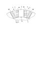
- FIG. 2 only a part of the first coil 6 and the second coil 7 fitted on the stator 3 and its teeth 4 are shown by solid lines, and the other parts are shown by two-dot chain lines. Specific illustration is omitted.
- the coil 5 that is externally fitted to the tooth 4 is divided into two, the first coil 6 and the second coil 7, and the teeth 4 are arranged radially inward. Since the first coil 6 is externally fitted and the second coil 7 is externally fitted radially outward, the winding of the second coil 7 is larger than the number of turns of the first coil 6 as shown in FIG. The number can be increased, and in this way, as many coils 5 as possible can be arranged in the fan-shaped space between adjacent teeth 4 and the space factor can be increased. Thus, according to the electric motor 1 of this example, since the space factor of the coil 5 in the space between the teeth 4 can be further increased as compared with the conventional one, the electric motor 1 can output more than the conventional one. Can be expensive.
- FIG. 7 shows a coil 100 formed by winding a flat wire edgewise, which is known as one of the conventional modes.
- the coil 5 which concerns on the electric motor 1 of this example is shown with a dashed-two dotted line.
- the long side of the flat wire has a base end portion 4a of the teeth 4 and an intermediate position of the space between the teeth (an intermediate line W indicated by a two-dot chain line). Therefore, an empty space in which the coil 100 does not exist is formed in the radially outer portion of the space between the teeth. Therefore, in the electric motor 1 of this example, In comparison, the space factor of the coil 100 is low.
- stator 3 and the first coil 6 and the second coil 7 fitted on the teeth 4 are partially enlarged.
- the coil 100 externally fitted to the tooth 4 is shown partially enlarged, and hatching to the cross section of the first coil 6 and the second coil 7 in FIG. 6 and hatching to the cross section of the coil 100 in FIG. Omits this.
- the winding start end portions 6a and 7a and the winding end ends 6b and 7b of the first coil 6 and the second coil 7 are bent 90 degrees edgewise, respectively.
- the winding start end 6 a of the first coil 6 is connected to the second coil 7.
- the winding start end portion 6a of the first coil 6 and the winding start end portion 7a of the second coil 7 are arranged side by side through the ring of the laminated winding portion, and the winding end end portion of the first coil 6 6b is located above the second coil 7, and similarly, the winding end 6b of the first coil 6 and the winding end 7b of the second coil 7 are arranged side by side. .
- the winding start end portions 6a, 7a Connection can be made without projecting the outer periphery of the first coil 6 or the second coil 7, and the electric motor 1 can be made compact.
- the winding start ends 6b, 7b are connected to each other. Connection can be made without projecting to the outer peripheral portion of the first coil 6 or the second coil 7, and the electric motor 1 can be made compact in this aspect as well.
- the space factor can be increased as compared to the round wire, and if the rectangular wire is wound flatwise and formed into a laminated shape. Compared with the case of winding in an edgewise manner, there is an advantage that molding is easy and a special and expensive device is not required for the production.
- the coil 5 is divided into the first coil 6 and the second coil 7, and the number of turns of the first coil 6 and the number of turns of the second coil 7 are different.
- the first coil 6 having a small number of turns is used for high-speed rotation for rotating the rotor 10 at a high speed
- the second coil 7 having a large number of turns is used for the rotor 10. It can be used for low speed rotation that rotates at low speed.
- stator 3 and its teeth 4 are not limited to the above examples. As long as the object of the present invention is achieved, any known shape of stator 3 and teeth 4 can be applied.
Landscapes
- Engineering & Computer Science (AREA)
- Power Engineering (AREA)
- Windings For Motors And Generators (AREA)
Abstract
コンパクトな構成を阻害されることなく、従来に比べてより高出力化が図られた電動機を提供する。電動機は、ハウジングと、該ハウジング内に、中心軸を中心として回転可能に設けられる回転子と、ハウジング内で回転子の周囲に配設される固定子3とを備える。固定子3は、回転子の中心軸を中心として半径方向に放射状に設けられた複数のティース4を備え、各ティース4には、環状に巻回されたコイル5が外嵌される。コイル5は、半径方向内側に配置される第1のコイル6と、半径方向外側に配置される第2のコイル7とからなり、第1のコイル6は、その巻回内側の端部6aが半径方向外側に曲げられて、積層巻回部から外方に延出され、更に、ティース4に外嵌された状態で、この巻回内側の端部6aが、第2のコイル7の積層巻回部の環内に挿通されるように配置される。
Description
本発明は、ハウジングと、このハウジング内に、中心軸を中心として回転可能に設けられる回転子と、ハウジング内で前記回転子の周囲に配設される固定子とを備えた電動機に関する。
前記電動機として、従来、前記固定子が前記回転子の中心軸を中心として半径方向に放射状に設けられた複数のティースを備え、各ティースに、環状に巻回されたコイルを外嵌した構成の電動機が知られている。そして、このような構成を有する電動機の一つとして、従来、特開2015-42113号公報(下記特許文献1)に開示される電動機が提案されている。
具体的には、前記特許文献1に開示される電動機では、前記ティースに巻き付けるコイルとして平角線を用い、この平角線をフラットワイズ巻きで、層状に重ならないように、しかも隣り合う平角線同士が接触しないように隙間を空けて前記コイルに巻き付けるとともに、コイルとティースを樹脂で固定した構成を備えている。
この特許文献1に開示される電動機では、コイルの放熱性を高めるために上記構成を採用しており、かかる構成とすることで、一重に巻回された平角線の長方形断面の長辺側がティース及び樹脂に接触し、これによって放熱性が向上するとのことである。
ところで、前記特許文献1にも記載されるように、電動機の出力は、コイルの通電電流[A]×巻き数[turn]で決定され、高出力の電動機を得るには、限られた空間内に配置されるコイルの総断面積をできるだけ大きくするのが好ましい。
したがって、より高出力の電動機を得るには、上述した放熱性については別の工夫を要するものの、前記ティースにできるだけ多くのコイルを巻き付けて、その総断面積を大きくするような工夫が求められる。
一方、機械,機器及び器具などにおける普遍的な設計上の要請から、このような高出力化が図られる電動機においても、全体的なコンパクト化が求められており、したがって、高出力にすべく、前記ティースにできるだけ多くのコイルを巻き付けて、その総断面積を大きくするような場合においても、当該コイルを前記ティースにコンパクトに外嵌することができる構造が求められる。
本発明は、以上の実情に鑑みなされたものであって、コンパクトな構成を阻害されることなく、従来に比べてより高出力化が図られた電動機の提供を、その目的とする。
上記課題を解決するための本発明は、ハウジングと、該ハウジング内に、中心軸を中心として回転可能に設けられる回転子と、前記ハウジング内で前記回転子の周囲に配設される固定子とを備えた電動機であって、
前記固定子は、前記回転子の中心軸を中心として半径方向に放射状に設けられた複数のティースを備え、
前記各ティースには、環状に巻回されたコイルが外嵌されて構成される電動機において、
前記各ティースには、前記半径方向内側に配置される第1のコイルと、半径方向外側に配置される第2のコイルとがそれぞれ外嵌され、
前記第1のコイルは、その巻回内側の端部が前記半径方向外側に曲げられて、積層巻回部から外方に延出され、更に、前記ティースに外嵌された状態で、前記巻回内側の端部が、前記第2のコイルの積層巻回部の環内に挿通されるように配置された電動機に係る。
前記固定子は、前記回転子の中心軸を中心として半径方向に放射状に設けられた複数のティースを備え、
前記各ティースには、環状に巻回されたコイルが外嵌されて構成される電動機において、
前記各ティースには、前記半径方向内側に配置される第1のコイルと、半径方向外側に配置される第2のコイルとがそれぞれ外嵌され、
前記第1のコイルは、その巻回内側の端部が前記半径方向外側に曲げられて、積層巻回部から外方に延出され、更に、前記ティースに外嵌された状態で、前記巻回内側の端部が、前記第2のコイルの積層巻回部の環内に挿通されるように配置された電動機に係る。
上述のように、本発明に係る電動機では、前記ティースの前記半径方向内側に第1のコイルが外嵌され、半径方向外側に第2のコイルが外嵌される。隣接する各ティース間の空間は、その横断面の形状が扇形をしているため、前記第1のコイルの巻き数に比べて、前記第2のコイルの巻き数を多くすることができ、第1のコイルと第2のコイルとを、このような巻き数にすることで、前記ティース間の空間内にできるだけ多くのコイルを配置することができる。言い換えれば、前記空間内における、前記コイルの所謂占積率を高めることができる。したがって、本発明に係る電動機によれば、従来に比べて、より高い出力が得ることができる。
また、本発明に係る電動機において、前記第1のコイルは、その巻回内側の端部(即ち、巻き始め側の端部であり、以下、「一端部」という)が前記半径方向外側に曲げられて、積層巻回部から外方に延出され、更に、前記ティースに外嵌された状態で、前記一端部が、前記第2のコイルの積層巻回部の環内に挿通されるように配置されているので、当該一端部を他の配線と結線する際に、当該一端部を第1のコイルや第2のコイルの外周部に張り出させることなく結線することができ、電動機のコンパクト化を図ることができる。
また、本発明において、前記第1のコイル及び第2のコイルは、それぞれ平角線をフラットワイズに積層状に巻回することによって形成されるとともに、その一端部がそれぞれエッジワイズに曲げられて、積層巻回部から外方に延出され、更に、前記ティースに外嵌された状態で、前記第1のコイルの前記一端部が、前記第2のコイルの積層巻回部の環内に挿通されるように配置されていても良い。
このように、第1のコイル及び第2のコイルを、それぞれ平角線をフラットワイズに積層状に巻回して形成することで、その前記占積率を高めることができる。また、その一端部をそれぞれエッジワイズに曲げて、積層巻回部から外方に延出するとともに、前記ティースに外嵌された状態で、前記第1のコイルの前記一端部を、前記第2のコイルの積層巻回部の環内に挿通するようにすることで、上述した如く、電動機のコンパクト化を図ることができる。
また、平角線を用いることで、丸線に比べて占積率を高めることができ、更に、平角線をフラットワイズに巻回して積層状に形成すれば、エッジワイズに巻回する場合に比べて、成形が容易であり、その製造に当たって、特殊で高価な装置を要しないというメリットもある。
尚、前記フラットワイズとは、平角線の長辺で形成される面が内周面及び外周面となるような巻き方及び曲げ方を言う。また、前記エッジワイズとは、平角線の短辺で形成される面が内周面及び外周面となるような巻き方及び曲げ方を言う。
また、本発明において、前記第1のコイルは、その前記一端部が、前記第2のコイルの積層巻回部の環内に挿通された状態で、前記半径方向と直交する幅方向において、前記第2のコイルの前記一端部と横並びで配置されるように構成されていても良い。このようにすることで、よりコンパクト化が図られるとともに、両者間を結線する際、或いは他の配線と結線する際の容易化が図られる。
また、本発明において、前記第1のコイル及び第2のコイルは、それぞれ巻回外側の端部(即ち、巻き終わり側の端部であり、以下、「他端部」という)がエッジワイズに曲げられて、積層巻回部から外方に延出され、更に、前記ティースに外嵌された状態で、第1のコイルの他端部と第2のコイルの他端部とが、前記半径方向と直交する幅方向において、横並びで配置されるように構成されていても良い。
このようにすれば、前記第1のコイル及び第2のコイルの他端部を結線する際や、当該他端部と他の配線とを結線する際に、外周部への不要な張り出しを生じることなく結線することができ、電動機のコンパクト化を図ることができる。
以上のように、本発明によれば、前記ティースの半径方向内側に第1のコイルを外嵌し、半径方向外側に第2のコイルを外嵌した構成としたので、第1のコイルの巻き数に比べて、第2のコイルの巻き数を多くすることで、隣接する各ティース間の扇形をした空間内にできるだけ多くのコイルを配置して、その占積率を高めることができ、このようにすることで、従来に比べて、より高い出力が得られる電動機とすることができる。
また、前記第1のコイルは、その巻回内側の端部(一端部)が前記半径方向外側に曲げられて、積層巻回部から外方に延出され、更に、前記ティースに外嵌された状態で、前記一端部が、前記第2のコイルの積層巻回部の環内に挿通されるように配置されているので、当該一端部を他の配線と結線する際に、当該一端部を第1のコイルや第2のコイルの外周部に張り出させることなく結線することができ、電動機のコンパクト化を図ることができる。
以下、本発明の具体的な実施の形態について、図面を参照しながら説明する。
図1に示すように、本例の電動機1は、円筒状をした中空のハウジング2と、円筒状をした内径部を有し、前記ハウジング2内に配設される固定子3と、この固定子3内に回転自在に配設された回転子10とを備えて構成される。尚、本例では、発明の中核に関わる部分のみを図示し、電動機1の他の構成部分については、その図示と説明を省略するものとする。
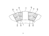
前記固定子3は、前記回転子10の中心軸Cを中心として半径方向に放射状に設けられた複数(本例では12個)のティース4を備えており、このティース4には、それぞれ環状に巻回されたコイル5が外嵌されている。
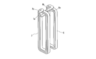
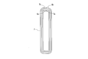
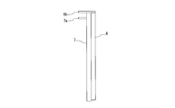
図2~図5に示すように、前記ティース4に外嵌されるコイル5は、前記半径方向の内側に配置される第1コイル6と、前記半径方向の外側に配置される第2コイル7とから成り、これら第1コイル6及び第2コイル7はそれぞれ平角線から構成され、この平角線をフラットワイズに巻回するとともに、各巻始め端部(巻回内側の端部)6a,7aを前記半径方向の外側に向けて90度エッジワイズに曲げて、積層巻回部から外方に延出させ、同様に、各巻終わり端部(巻回外側の端部)6b,7bを前記半径方向の外側に向けて90度エッジワイズに曲げて、積層巻回部から外方に延出させている。
尚、ここで言う前記フラットワイズとは、平角線の長辺で形成される面が内周面及び外周面となるような巻き方及び曲げ方を言い、前記エッジワイズとは、平角線の短辺で形成される面が内周面及び外周面となるような巻き方及び曲げ方を言う。
そして、これら第1コイル6及び第2コイル7は、これらを前記半径方向に重ね合せて前記ティース4に外嵌する際に、前記第1コイル6の巻始め端部6aが第2コイル7の積層巻回部の環内に挿通されて、第1コイル6の巻始め端部6aと第2コイル7の巻始め端部7aとが、前記半径方向と直交する方向に横並びとなり、また、前記第1コイル6の巻終わり端部6bが第2コイル7の上方に位置して、同様に、当該第1コイル6の巻終わり端部6bと第2コイル7の巻終わり端部7bとが、前記半径方向と直交する方向に横並びとなるように構成されている。
尚、図2には、固定子3、並びにそのティース4に外嵌される第1コイル6及び第2コイル7の一部のみを実線で示し、他の部分は二点鎖線で示して、その具体的な図示を省略している。
斯くして、以上の構成を備えた本例の電動機1では、ティース4に外嵌するコイル5を第1コイル6と第2コイル7の2つに分割して、ティース4の半径方向内側に第1コイル6を外嵌し、半径方向外側に第2コイル7を外嵌した構成としたので、図6に示すように、第1コイル6の巻き数に比べて、第2コイル7の巻き数を多くすることができ、このようにすることで、隣接する各ティース4間の扇形をした空間内にできるだけ多くのコイル5を配置して、その占積率を高めることができる。このように、本例の電動機1によれば、従来に比べて各ティース4間の空間におけるコイル5の占積率をより高めることができるので、当該電動機1を、従来に比べてより出力の高いものとすることができる。
比較のために、従来の態様の一つとして知られている、平角線をエッジワイズに巻回して形成したコイル100を、図7に示す。また、図7において、本例の電動機1に係るコイル5を二点鎖線で示す。同図7に示すように、この態様のコイル100では、平角線の長辺が、ティース4の基端部4aと、各ティース間の空間の中間位置(二点鎖線で示す中間線W)との間に収まるような長さLにする必要があるため、各ティース間の空間の、前記半径方向外側の部分に、コイル100が存在しない空き空間を生じ、このため、本例の電動機1に比べて、コイル100の占積率が低いものとなるのである。
尚、図6には、固定子3、並びにそのティース4に外嵌される第1コイル6及び第2コイル7を一部拡大して示し、同様に、図7には、固定子3、並びにそのティース4に外嵌されるコイル100を一部拡大して示しており、図6における第1コイル6及び第2コイル7の断面へのハッチング、並びに、図7におけるコイル100の断面へのハッチングは、これを省略している。
また、本例の電動機1では、上述したように、第1コイル6及び第2コイル7の巻始め端部6a,7a及び巻終わり端部6b,7bをそれぞれ90度エッジワイズに曲げて、積層巻回部から外方に延出させるとともに、これら第1コイル6及び第2コイル7を前記ティース4に外嵌する際に、前記第1コイル6の巻始め端部6aを第2コイル7の積層巻回部の環内に挿通して、第1コイル6の巻始め端部6aと第2コイル7の巻始め端部7aとを横並びにし、また、前記第1コイル6の巻終わり端部6bを第2コイル7の上方に位置させて、同様に、当該第1コイル6の巻終わり端部6bと第2コイル7の巻終わり端部7bとを、横並びになるように構成している。
したがって、当該巻始め端部6aと巻始め端部7aとを結線する、或いは、これら巻始め端部6a,7aと他の配線とを結線する際に、当該巻始め端部6a,7aを第1コイル6や第2コイル7の外周部に張り出させることなく結線することができ、当該電動機1のコンパクト化を図ることができる。同様に、前記巻終わり端部6bと巻終わり端部7bとを結線する、或いは、これら巻終わり端部6b,7bと他の配線とを結線する際に、当該巻始め端部6b,7bを第1コイル6や第2コイル7の外周部に張り出させることなく結線することができ、この面でも、当該電動機1のコンパクト化を図ることができる。
また、第1コイル6及び第2コイル7に平角線を用いることで、丸線に比べて占積率を高めることができ、また、平角線をフラットワイズに巻回して積層状に形成すれば、エッジワイズに巻回する場合に比べて、成形が容易であり、その製造に当たって、特殊で高価な装置を要しないというメリットもある。
また、本例の電動機1では、上述したように、コイル5を第1コイル6と第2コイル7に分割するとともに、第1コイル6の巻き数と第2コイル7の巻き数とを異なる巻き数としているので、例えば、巻き数の少ない第1コイル6を、前記回転子10を高速で回転させる高速回転用として使用し、一方、巻き数の多い第2コイル7を、前記回転子10を低速で回転させる低速回転用として使用することができる。
以上、本発明の一実施形態について説明したが、本発明が採り得る具体的な態様は、何らこれに限定されるものではない。
例えば、上例では、第1コイル6及び第2コイル7に平角線を用いたが、これに限られるものではなく、幾分占積率が落ちるが丸線であっても良い。
また、前記固定子3及びそのティース4の形状は上例のものに何ら限定されるものではない。本発明の目的が達成される範囲内で、公知のあらゆる形状の固定子3及びティース4を適用することができる。
1 電動機
2 ハウジング
3 固定子
4 ティース
5 コイル
6 第1コイル
6a 巻始め端部
6b 巻終わり端部
7 第2コイル
7a 巻始め端部
7b 巻終わり端部
10 回転子
2 ハウジング
3 固定子
4 ティース
5 コイル
6 第1コイル
6a 巻始め端部
6b 巻終わり端部
7 第2コイル
7a 巻始め端部
7b 巻終わり端部
10 回転子
Claims (5)
- ハウジングと、該ハウジング内に、中心軸を中心として回転可能に設けられる回転子と、前記ハウジング内で前記回転子の周囲に配設される固定子とを備えた電動機であって、
前記固定子は、前記回転子の中心軸を中心として半径方向に放射状に設けられた複数のティースを備え、
前記各ティースには、環状に巻回されたコイルが外嵌されて構成される電動機において、
前記各ティースには、前記半径方向内側に配置される第1のコイルと、半径方向外側に配置される第2のコイルとがそれぞれ外嵌され、
前記第1のコイルは、その巻回内側の端部が前記半径方向外側に曲げられて、積層巻回部から外方に延出され、更に、前記ティースに外嵌された状態で、前記巻回内側の端部が、前記第2のコイルの積層巻回部の環内に挿通されるように配置されていることを特徴とする電動機。 - 前記第1のコイル及び第2のコイルは、それぞれ平角線をフラットワイズに積層状に巻回することによって形成されるとともに、その巻回内側の端部がそれぞれエッジワイズに曲げられて、積層巻回部から外方に延出され、更に、前記ティースに外嵌された状態で、前記第1のコイルの前記巻回内側の端部が、前記第2のコイルの積層巻回部の環内に挿通されるように配置されていることを特徴とする請求項1記載の電動機。
- 前記第1のコイルは、その前記巻回内側の端部が、前記第2のコイルの積層巻回部の環内に挿通された状態で、前記半径方向と直交する幅方向において、前記第2のコイルの前記巻回内側の端部と横並びで配置されるように構成されていることを特徴とする請求項2記載の電動機。
- 前記第1のコイル及び第2のコイルは、それぞれ巻回外側の端部がエッジワイズに曲げられて、積層巻回部から外方に延出され、更に、前記ティースに外嵌された状態で、第1のコイルの前記巻回外側の端部と第2のコイルの前記巻回外側の端部とが、前記半径方向と直交する幅方向において、横並びで配置されるように構成されていることを特徴とする請求項2記載の電動機。
- 前記第1のコイル及び第2のコイルは、それぞれ巻回外側の端部がエッジワイズに曲げられて、積層巻回部から外方に延出され、更に、前記ティースに外嵌された状態で、第1のコイルの前記巻回外側の端部と第2のコイルの前記巻回外側の端部とが、前記半径方向と直交する幅方向において、横並びで配置されるように構成されていることを特徴とする請求項3記載の電動機。
Applications Claiming Priority (2)
| Application Number | Priority Date | Filing Date | Title |
|---|---|---|---|
| JP2015196356A JP6118869B2 (ja) | 2015-10-02 | 2015-10-02 | 電動機 |
| JP2015-196356 | 2015-10-02 |
Publications (1)
| Publication Number | Publication Date |
|---|---|
| WO2017056548A1 true WO2017056548A1 (ja) | 2017-04-06 |
Family
ID=58424085
Family Applications (1)
| Application Number | Title | Priority Date | Filing Date |
|---|---|---|---|
| PCT/JP2016/065419 Ceased WO2017056548A1 (ja) | 2015-10-02 | 2016-05-25 | 電動機 |
Country Status (2)
| Country | Link |
|---|---|
| JP (1) | JP6118869B2 (ja) |
| WO (1) | WO2017056548A1 (ja) |
Families Citing this family (1)
| Publication number | Priority date | Publication date | Assignee | Title |
|---|---|---|---|---|
| JP2023114221A (ja) * | 2022-02-04 | 2023-08-17 | ニデック株式会社 | モータおよび航空機 |
Citations (3)
| Publication number | Priority date | Publication date | Assignee | Title |
|---|---|---|---|---|
| JP2004015878A (ja) * | 2002-06-05 | 2004-01-15 | Nissan Motor Co Ltd | 電動機の固定子構造およびその製造方法 |
| JP2004072824A (ja) * | 2002-08-01 | 2004-03-04 | Yaskawa Electric Corp | Acモータの固定子 |
| JP2010124636A (ja) * | 2008-11-20 | 2010-06-03 | Sumitomo Electric Ind Ltd | コイルユニットおよびステータ |
-
2015
- 2015-10-02 JP JP2015196356A patent/JP6118869B2/ja active Active
-
2016
- 2016-05-25 WO PCT/JP2016/065419 patent/WO2017056548A1/ja not_active Ceased
Patent Citations (3)
| Publication number | Priority date | Publication date | Assignee | Title |
|---|---|---|---|---|
| JP2004015878A (ja) * | 2002-06-05 | 2004-01-15 | Nissan Motor Co Ltd | 電動機の固定子構造およびその製造方法 |
| JP2004072824A (ja) * | 2002-08-01 | 2004-03-04 | Yaskawa Electric Corp | Acモータの固定子 |
| JP2010124636A (ja) * | 2008-11-20 | 2010-06-03 | Sumitomo Electric Ind Ltd | コイルユニットおよびステータ |
Also Published As
| Publication number | Publication date |
|---|---|
| JP6118869B2 (ja) | 2017-04-19 |
| JP2017070155A (ja) | 2017-04-06 |
Similar Documents
| Publication | Publication Date | Title |
|---|---|---|
| JP5306411B2 (ja) | 回転電機 | |
| JP6072238B2 (ja) | 回転電機の製造方法 | |
| JP5789570B2 (ja) | ステータ | |
| CN103683615A (zh) | 发夹连接装置和包括其的发夹绕组电机 | |
| WO2013145976A1 (ja) | 回転電機のステータ構造 | |
| JP2008245489A (ja) | 回転電機の固定子 | |
| JP5380043B2 (ja) | 回転電機 | |
| JP6626514B2 (ja) | 回転電機 | |
| JP2004260985A (ja) | 回転電機の電機子およびそれを用いた回転電機、ならびに回転電機の電機子製造方法 | |
| WO2015092884A1 (ja) | 回転電機 | |
| WO2015133518A1 (ja) | アーマチュアコア、アーマチュア、および電動モータ | |
| JP6667634B2 (ja) | 回転電機 | |
| JP5370245B2 (ja) | 回転電機の固定子の製造方法 | |
| JP2014187856A (ja) | ステータコアの絶縁構造及びステータの組付方法 | |
| JP6210705B2 (ja) | 回転電機およびそれに用いられる固定子 | |
| JP5309674B2 (ja) | 固定子コイルの製造方法 | |
| JP6118869B2 (ja) | 電動機 | |
| JPWO2021240851A5 (ja) | ||
| WO2019102736A1 (ja) | 回転電機、固定子 | |
| JP2019037103A (ja) | ステータ及びモータ | |
| JP2018198516A (ja) | 回転電機 | |
| JP6742263B2 (ja) | 回転電機 | |
| WO2014157621A1 (ja) | ステータの構造 | |
| JP6047070B2 (ja) | 電機子及び電機子の製造方法 | |
| JP5660402B2 (ja) | 回転電機 |
Legal Events
| Date | Code | Title | Description |
|---|---|---|---|
| 121 | Ep: the epo has been informed by wipo that ep was designated in this application |
Ref document number: 16850725 Country of ref document: EP Kind code of ref document: A1 |
|
| NENP | Non-entry into the national phase |
Ref country code: DE |
|
| 122 | Ep: pct application non-entry in european phase |
Ref document number: 16850725 Country of ref document: EP Kind code of ref document: A1 |