WO2017051824A1 - 流体圧制御装置 - Google Patents
流体圧制御装置 Download PDFInfo
- Publication number
- WO2017051824A1 WO2017051824A1 PCT/JP2016/077842 JP2016077842W WO2017051824A1 WO 2017051824 A1 WO2017051824 A1 WO 2017051824A1 JP 2016077842 W JP2016077842 W JP 2016077842W WO 2017051824 A1 WO2017051824 A1 WO 2017051824A1
- Authority
- WO
- WIPO (PCT)
- Prior art keywords
- pressure
- chamber
- pilot
- valve
- relief
- Prior art date
Links
Images


Classifications
-
- E—FIXED CONSTRUCTIONS
- E02—HYDRAULIC ENGINEERING; FOUNDATIONS; SOIL SHIFTING
- E02F—DREDGING; SOIL-SHIFTING
- E02F9/00—Component parts of dredgers or soil-shifting machines, not restricted to one of the kinds covered by groups E02F3/00 - E02F7/00
- E02F9/20—Drives; Control devices
- E02F9/22—Hydraulic or pneumatic drives
- E02F9/2221—Control of flow rate; Load sensing arrangements
- E02F9/2225—Control of flow rate; Load sensing arrangements using pressure-compensating valves
-
- E—FIXED CONSTRUCTIONS
- E02—HYDRAULIC ENGINEERING; FOUNDATIONS; SOIL SHIFTING
- E02F—DREDGING; SOIL-SHIFTING
- E02F9/00—Component parts of dredgers or soil-shifting machines, not restricted to one of the kinds covered by groups E02F3/00 - E02F7/00
- E02F9/20—Drives; Control devices
- E02F9/22—Hydraulic or pneumatic drives
- E02F9/2221—Control of flow rate; Load sensing arrangements
-
- F—MECHANICAL ENGINEERING; LIGHTING; HEATING; WEAPONS; BLASTING
- F15—FLUID-PRESSURE ACTUATORS; HYDRAULICS OR PNEUMATICS IN GENERAL
- F15B—SYSTEMS ACTING BY MEANS OF FLUIDS IN GENERAL; FLUID-PRESSURE ACTUATORS, e.g. SERVOMOTORS; DETAILS OF FLUID-PRESSURE SYSTEMS, NOT OTHERWISE PROVIDED FOR
- F15B11/00—Servomotor systems without provision for follow-up action; Circuits therefor
- F15B11/003—Systems with load-holding valves
-
- E—FIXED CONSTRUCTIONS
- E02—HYDRAULIC ENGINEERING; FOUNDATIONS; SOIL SHIFTING
- E02F—DREDGING; SOIL-SHIFTING
- E02F9/00—Component parts of dredgers or soil-shifting machines, not restricted to one of the kinds covered by groups E02F3/00 - E02F7/00
- E02F9/20—Drives; Control devices
- E02F9/22—Hydraulic or pneumatic drives
- E02F9/2264—Arrangements or adaptations of elements for hydraulic drives
- E02F9/2267—Valves or distributors
-
- E—FIXED CONSTRUCTIONS
- E02—HYDRAULIC ENGINEERING; FOUNDATIONS; SOIL SHIFTING
- E02F—DREDGING; SOIL-SHIFTING
- E02F9/00—Component parts of dredgers or soil-shifting machines, not restricted to one of the kinds covered by groups E02F3/00 - E02F7/00
- E02F9/20—Drives; Control devices
- E02F9/22—Hydraulic or pneumatic drives
- E02F9/2278—Hydraulic circuits
- E02F9/2285—Pilot-operated systems
-
- F—MECHANICAL ENGINEERING; LIGHTING; HEATING; WEAPONS; BLASTING
- F15—FLUID-PRESSURE ACTUATORS; HYDRAULICS OR PNEUMATICS IN GENERAL
- F15B—SYSTEMS ACTING BY MEANS OF FLUIDS IN GENERAL; FLUID-PRESSURE ACTUATORS, e.g. SERVOMOTORS; DETAILS OF FLUID-PRESSURE SYSTEMS, NOT OTHERWISE PROVIDED FOR
- F15B11/00—Servomotor systems without provision for follow-up action; Circuits therefor
- F15B11/02—Systems essentially incorporating special features for controlling the speed or actuating force of an output member
- F15B11/04—Systems essentially incorporating special features for controlling the speed or actuating force of an output member for controlling the speed
- F15B11/044—Systems essentially incorporating special features for controlling the speed or actuating force of an output member for controlling the speed by means in the return line, i.e. "meter out"
-
- F—MECHANICAL ENGINEERING; LIGHTING; HEATING; WEAPONS; BLASTING
- F15—FLUID-PRESSURE ACTUATORS; HYDRAULICS OR PNEUMATICS IN GENERAL
- F15B—SYSTEMS ACTING BY MEANS OF FLUIDS IN GENERAL; FLUID-PRESSURE ACTUATORS, e.g. SERVOMOTORS; DETAILS OF FLUID-PRESSURE SYSTEMS, NOT OTHERWISE PROVIDED FOR
- F15B13/00—Details of servomotor systems ; Valves for servomotor systems
- F15B13/01—Locking-valves or other detent i.e. load-holding devices
-
- F—MECHANICAL ENGINEERING; LIGHTING; HEATING; WEAPONS; BLASTING
- F15—FLUID-PRESSURE ACTUATORS; HYDRAULICS OR PNEUMATICS IN GENERAL
- F15B—SYSTEMS ACTING BY MEANS OF FLUIDS IN GENERAL; FLUID-PRESSURE ACTUATORS, e.g. SERVOMOTORS; DETAILS OF FLUID-PRESSURE SYSTEMS, NOT OTHERWISE PROVIDED FOR
- F15B13/00—Details of servomotor systems ; Valves for servomotor systems
- F15B13/02—Fluid distribution or supply devices characterised by their adaptation to the control of servomotors
- F15B13/024—Pressure relief valves
-
- F—MECHANICAL ENGINEERING; LIGHTING; HEATING; WEAPONS; BLASTING
- F15—FLUID-PRESSURE ACTUATORS; HYDRAULICS OR PNEUMATICS IN GENERAL
- F15B—SYSTEMS ACTING BY MEANS OF FLUIDS IN GENERAL; FLUID-PRESSURE ACTUATORS, e.g. SERVOMOTORS; DETAILS OF FLUID-PRESSURE SYSTEMS, NOT OTHERWISE PROVIDED FOR
- F15B11/00—Servomotor systems without provision for follow-up action; Circuits therefor
- F15B11/08—Servomotor systems without provision for follow-up action; Circuits therefor with only one servomotor
- F15B11/15—Servomotor systems without provision for follow-up action; Circuits therefor with only one servomotor with special provision for automatic return
-
- F—MECHANICAL ENGINEERING; LIGHTING; HEATING; WEAPONS; BLASTING
- F15—FLUID-PRESSURE ACTUATORS; HYDRAULICS OR PNEUMATICS IN GENERAL
- F15B—SYSTEMS ACTING BY MEANS OF FLUIDS IN GENERAL; FLUID-PRESSURE ACTUATORS, e.g. SERVOMOTORS; DETAILS OF FLUID-PRESSURE SYSTEMS, NOT OTHERWISE PROVIDED FOR
- F15B13/00—Details of servomotor systems ; Valves for servomotor systems
- F15B13/02—Fluid distribution or supply devices characterised by their adaptation to the control of servomotors
- F15B13/027—Check valves
-
- F—MECHANICAL ENGINEERING; LIGHTING; HEATING; WEAPONS; BLASTING
- F15—FLUID-PRESSURE ACTUATORS; HYDRAULICS OR PNEUMATICS IN GENERAL
- F15B—SYSTEMS ACTING BY MEANS OF FLUIDS IN GENERAL; FLUID-PRESSURE ACTUATORS, e.g. SERVOMOTORS; DETAILS OF FLUID-PRESSURE SYSTEMS, NOT OTHERWISE PROVIDED FOR
- F15B13/00—Details of servomotor systems ; Valves for servomotor systems
- F15B13/02—Fluid distribution or supply devices characterised by their adaptation to the control of servomotors
- F15B13/04—Fluid distribution or supply devices characterised by their adaptation to the control of servomotors for use with a single servomotor
- F15B13/0401—Valve members; Fluid interconnections therefor
- F15B13/0405—Valve members; Fluid interconnections therefor for seat valves, i.e. poppet valves
-
- F—MECHANICAL ENGINEERING; LIGHTING; HEATING; WEAPONS; BLASTING
- F15—FLUID-PRESSURE ACTUATORS; HYDRAULICS OR PNEUMATICS IN GENERAL
- F15B—SYSTEMS ACTING BY MEANS OF FLUIDS IN GENERAL; FLUID-PRESSURE ACTUATORS, e.g. SERVOMOTORS; DETAILS OF FLUID-PRESSURE SYSTEMS, NOT OTHERWISE PROVIDED FOR
- F15B13/00—Details of servomotor systems ; Valves for servomotor systems
- F15B13/02—Fluid distribution or supply devices characterised by their adaptation to the control of servomotors
- F15B13/04—Fluid distribution or supply devices characterised by their adaptation to the control of servomotors for use with a single servomotor
- F15B13/0401—Valve members; Fluid interconnections therefor
- F15B13/0407—Means for damping the valve member movement
-
- F—MECHANICAL ENGINEERING; LIGHTING; HEATING; WEAPONS; BLASTING
- F15—FLUID-PRESSURE ACTUATORS; HYDRAULICS OR PNEUMATICS IN GENERAL
- F15B—SYSTEMS ACTING BY MEANS OF FLUIDS IN GENERAL; FLUID-PRESSURE ACTUATORS, e.g. SERVOMOTORS; DETAILS OF FLUID-PRESSURE SYSTEMS, NOT OTHERWISE PROVIDED FOR
- F15B20/00—Safety arrangements for fluid actuator systems; Applications of safety devices in fluid actuator systems; Emergency measures for fluid actuator systems
- F15B20/005—Leakage; Spillage; Hose burst
-
- F—MECHANICAL ENGINEERING; LIGHTING; HEATING; WEAPONS; BLASTING
- F15—FLUID-PRESSURE ACTUATORS; HYDRAULICS OR PNEUMATICS IN GENERAL
- F15B—SYSTEMS ACTING BY MEANS OF FLUIDS IN GENERAL; FLUID-PRESSURE ACTUATORS, e.g. SERVOMOTORS; DETAILS OF FLUID-PRESSURE SYSTEMS, NOT OTHERWISE PROVIDED FOR
- F15B2211/00—Circuits for servomotor systems
- F15B2211/30—Directional control
- F15B2211/305—Directional control characterised by the type of valves
- F15B2211/30505—Non-return valves, i.e. check valves
- F15B2211/30515—Load holding valves
-
- F—MECHANICAL ENGINEERING; LIGHTING; HEATING; WEAPONS; BLASTING
- F15—FLUID-PRESSURE ACTUATORS; HYDRAULICS OR PNEUMATICS IN GENERAL
- F15B—SYSTEMS ACTING BY MEANS OF FLUIDS IN GENERAL; FLUID-PRESSURE ACTUATORS, e.g. SERVOMOTORS; DETAILS OF FLUID-PRESSURE SYSTEMS, NOT OTHERWISE PROVIDED FOR
- F15B2211/00—Circuits for servomotor systems
- F15B2211/30—Directional control
- F15B2211/31—Directional control characterised by the positions of the valve element
- F15B2211/3105—Neutral or centre positions
- F15B2211/3111—Neutral or centre positions the pump port being closed in the centre position, e.g. so-called closed centre
-
- F—MECHANICAL ENGINEERING; LIGHTING; HEATING; WEAPONS; BLASTING
- F15—FLUID-PRESSURE ACTUATORS; HYDRAULICS OR PNEUMATICS IN GENERAL
- F15B—SYSTEMS ACTING BY MEANS OF FLUIDS IN GENERAL; FLUID-PRESSURE ACTUATORS, e.g. SERVOMOTORS; DETAILS OF FLUID-PRESSURE SYSTEMS, NOT OTHERWISE PROVIDED FOR
- F15B2211/00—Circuits for servomotor systems
- F15B2211/30—Directional control
- F15B2211/32—Directional control characterised by the type of actuation
- F15B2211/329—Directional control characterised by the type of actuation actuated by fluid pressure
-
- F—MECHANICAL ENGINEERING; LIGHTING; HEATING; WEAPONS; BLASTING
- F15—FLUID-PRESSURE ACTUATORS; HYDRAULICS OR PNEUMATICS IN GENERAL
- F15B—SYSTEMS ACTING BY MEANS OF FLUIDS IN GENERAL; FLUID-PRESSURE ACTUATORS, e.g. SERVOMOTORS; DETAILS OF FLUID-PRESSURE SYSTEMS, NOT OTHERWISE PROVIDED FOR
- F15B2211/00—Circuits for servomotor systems
- F15B2211/30—Directional control
- F15B2211/355—Pilot pressure control
-
- F—MECHANICAL ENGINEERING; LIGHTING; HEATING; WEAPONS; BLASTING
- F15—FLUID-PRESSURE ACTUATORS; HYDRAULICS OR PNEUMATICS IN GENERAL
- F15B—SYSTEMS ACTING BY MEANS OF FLUIDS IN GENERAL; FLUID-PRESSURE ACTUATORS, e.g. SERVOMOTORS; DETAILS OF FLUID-PRESSURE SYSTEMS, NOT OTHERWISE PROVIDED FOR
- F15B2211/00—Circuits for servomotor systems
- F15B2211/40—Flow control
- F15B2211/405—Flow control characterised by the type of flow control means or valve
- F15B2211/40515—Flow control characterised by the type of flow control means or valve with variable throttles or orifices
-
- F—MECHANICAL ENGINEERING; LIGHTING; HEATING; WEAPONS; BLASTING
- F15—FLUID-PRESSURE ACTUATORS; HYDRAULICS OR PNEUMATICS IN GENERAL
- F15B—SYSTEMS ACTING BY MEANS OF FLUIDS IN GENERAL; FLUID-PRESSURE ACTUATORS, e.g. SERVOMOTORS; DETAILS OF FLUID-PRESSURE SYSTEMS, NOT OTHERWISE PROVIDED FOR
- F15B2211/00—Circuits for servomotor systems
- F15B2211/40—Flow control
- F15B2211/41—Flow control characterised by the positions of the valve element
- F15B2211/413—Flow control characterised by the positions of the valve element the positions being continuously variable, e.g. as realised by proportional valves
-
- F—MECHANICAL ENGINEERING; LIGHTING; HEATING; WEAPONS; BLASTING
- F15—FLUID-PRESSURE ACTUATORS; HYDRAULICS OR PNEUMATICS IN GENERAL
- F15B—SYSTEMS ACTING BY MEANS OF FLUIDS IN GENERAL; FLUID-PRESSURE ACTUATORS, e.g. SERVOMOTORS; DETAILS OF FLUID-PRESSURE SYSTEMS, NOT OTHERWISE PROVIDED FOR
- F15B2211/00—Circuits for servomotor systems
- F15B2211/40—Flow control
- F15B2211/415—Flow control characterised by the connections of the flow control means in the circuit
- F15B2211/41527—Flow control characterised by the connections of the flow control means in the circuit being connected to an output member and a directional control valve
-
- F—MECHANICAL ENGINEERING; LIGHTING; HEATING; WEAPONS; BLASTING
- F15—FLUID-PRESSURE ACTUATORS; HYDRAULICS OR PNEUMATICS IN GENERAL
- F15B—SYSTEMS ACTING BY MEANS OF FLUIDS IN GENERAL; FLUID-PRESSURE ACTUATORS, e.g. SERVOMOTORS; DETAILS OF FLUID-PRESSURE SYSTEMS, NOT OTHERWISE PROVIDED FOR
- F15B2211/00—Circuits for servomotor systems
- F15B2211/40—Flow control
- F15B2211/42—Flow control characterised by the type of actuation
- F15B2211/428—Flow control characterised by the type of actuation actuated by fluid pressure
-
- F—MECHANICAL ENGINEERING; LIGHTING; HEATING; WEAPONS; BLASTING
- F15—FLUID-PRESSURE ACTUATORS; HYDRAULICS OR PNEUMATICS IN GENERAL
- F15B—SYSTEMS ACTING BY MEANS OF FLUIDS IN GENERAL; FLUID-PRESSURE ACTUATORS, e.g. SERVOMOTORS; DETAILS OF FLUID-PRESSURE SYSTEMS, NOT OTHERWISE PROVIDED FOR
- F15B2211/00—Circuits for servomotor systems
- F15B2211/40—Flow control
- F15B2211/46—Control of flow in the return line, i.e. meter-out control
-
- F—MECHANICAL ENGINEERING; LIGHTING; HEATING; WEAPONS; BLASTING
- F15—FLUID-PRESSURE ACTUATORS; HYDRAULICS OR PNEUMATICS IN GENERAL
- F15B—SYSTEMS ACTING BY MEANS OF FLUIDS IN GENERAL; FLUID-PRESSURE ACTUATORS, e.g. SERVOMOTORS; DETAILS OF FLUID-PRESSURE SYSTEMS, NOT OTHERWISE PROVIDED FOR
- F15B2211/00—Circuits for servomotor systems
- F15B2211/50—Pressure control
- F15B2211/505—Pressure control characterised by the type of pressure control means
- F15B2211/50509—Pressure control characterised by the type of pressure control means the pressure control means controlling a pressure upstream of the pressure control means
- F15B2211/50518—Pressure control characterised by the type of pressure control means the pressure control means controlling a pressure upstream of the pressure control means using pressure relief valves
-
- F—MECHANICAL ENGINEERING; LIGHTING; HEATING; WEAPONS; BLASTING
- F15—FLUID-PRESSURE ACTUATORS; HYDRAULICS OR PNEUMATICS IN GENERAL
- F15B—SYSTEMS ACTING BY MEANS OF FLUIDS IN GENERAL; FLUID-PRESSURE ACTUATORS, e.g. SERVOMOTORS; DETAILS OF FLUID-PRESSURE SYSTEMS, NOT OTHERWISE PROVIDED FOR
- F15B2211/00—Circuits for servomotor systems
- F15B2211/50—Pressure control
- F15B2211/515—Pressure control characterised by the connections of the pressure control means in the circuit
- F15B2211/5159—Pressure control characterised by the connections of the pressure control means in the circuit being connected to an output member and a return line
-
- F—MECHANICAL ENGINEERING; LIGHTING; HEATING; WEAPONS; BLASTING
- F15—FLUID-PRESSURE ACTUATORS; HYDRAULICS OR PNEUMATICS IN GENERAL
- F15B—SYSTEMS ACTING BY MEANS OF FLUIDS IN GENERAL; FLUID-PRESSURE ACTUATORS, e.g. SERVOMOTORS; DETAILS OF FLUID-PRESSURE SYSTEMS, NOT OTHERWISE PROVIDED FOR
- F15B2211/00—Circuits for servomotor systems
- F15B2211/50—Pressure control
- F15B2211/575—Pilot pressure control
- F15B2211/5753—Pilot pressure control for closing a valve
-
- F—MECHANICAL ENGINEERING; LIGHTING; HEATING; WEAPONS; BLASTING
- F15—FLUID-PRESSURE ACTUATORS; HYDRAULICS OR PNEUMATICS IN GENERAL
- F15B—SYSTEMS ACTING BY MEANS OF FLUIDS IN GENERAL; FLUID-PRESSURE ACTUATORS, e.g. SERVOMOTORS; DETAILS OF FLUID-PRESSURE SYSTEMS, NOT OTHERWISE PROVIDED FOR
- F15B2211/00—Circuits for servomotor systems
- F15B2211/50—Pressure control
- F15B2211/575—Pilot pressure control
- F15B2211/5756—Pilot pressure control for opening a valve
-
- F—MECHANICAL ENGINEERING; LIGHTING; HEATING; WEAPONS; BLASTING
- F15—FLUID-PRESSURE ACTUATORS; HYDRAULICS OR PNEUMATICS IN GENERAL
- F15B—SYSTEMS ACTING BY MEANS OF FLUIDS IN GENERAL; FLUID-PRESSURE ACTUATORS, e.g. SERVOMOTORS; DETAILS OF FLUID-PRESSURE SYSTEMS, NOT OTHERWISE PROVIDED FOR
- F15B2211/00—Circuits for servomotor systems
- F15B2211/60—Circuit components or control therefor
- F15B2211/635—Circuits providing pilot pressure to pilot pressure-controlled fluid circuit elements
- F15B2211/6355—Circuits providing pilot pressure to pilot pressure-controlled fluid circuit elements having valve means
-
- F—MECHANICAL ENGINEERING; LIGHTING; HEATING; WEAPONS; BLASTING
- F15—FLUID-PRESSURE ACTUATORS; HYDRAULICS OR PNEUMATICS IN GENERAL
- F15B—SYSTEMS ACTING BY MEANS OF FLUIDS IN GENERAL; FLUID-PRESSURE ACTUATORS, e.g. SERVOMOTORS; DETAILS OF FLUID-PRESSURE SYSTEMS, NOT OTHERWISE PROVIDED FOR
- F15B2211/00—Circuits for servomotor systems
- F15B2211/70—Output members, e.g. hydraulic motors or cylinders or control therefor
- F15B2211/76—Control of force or torque of the output member
- F15B2211/761—Control of a negative load, i.e. of a load generating hydraulic energy
-
- F—MECHANICAL ENGINEERING; LIGHTING; HEATING; WEAPONS; BLASTING
- F15—FLUID-PRESSURE ACTUATORS; HYDRAULICS OR PNEUMATICS IN GENERAL
- F15B—SYSTEMS ACTING BY MEANS OF FLUIDS IN GENERAL; FLUID-PRESSURE ACTUATORS, e.g. SERVOMOTORS; DETAILS OF FLUID-PRESSURE SYSTEMS, NOT OTHERWISE PROVIDED FOR
- F15B2211/00—Circuits for servomotor systems
- F15B2211/80—Other types of control related to particular problems or conditions
- F15B2211/86—Control during or prevention of abnormal conditions
- F15B2211/8613—Control during or prevention of abnormal conditions the abnormal condition being oscillations
-
- F—MECHANICAL ENGINEERING; LIGHTING; HEATING; WEAPONS; BLASTING
- F15—FLUID-PRESSURE ACTUATORS; HYDRAULICS OR PNEUMATICS IN GENERAL
- F15B—SYSTEMS ACTING BY MEANS OF FLUIDS IN GENERAL; FLUID-PRESSURE ACTUATORS, e.g. SERVOMOTORS; DETAILS OF FLUID-PRESSURE SYSTEMS, NOT OTHERWISE PROVIDED FOR
- F15B2211/00—Circuits for servomotor systems
- F15B2211/80—Other types of control related to particular problems or conditions
- F15B2211/86—Control during or prevention of abnormal conditions
- F15B2211/8616—Control during or prevention of abnormal conditions the abnormal condition being noise or vibration
-
- F—MECHANICAL ENGINEERING; LIGHTING; HEATING; WEAPONS; BLASTING
- F15—FLUID-PRESSURE ACTUATORS; HYDRAULICS OR PNEUMATICS IN GENERAL
- F15B—SYSTEMS ACTING BY MEANS OF FLUIDS IN GENERAL; FLUID-PRESSURE ACTUATORS, e.g. SERVOMOTORS; DETAILS OF FLUID-PRESSURE SYSTEMS, NOT OTHERWISE PROVIDED FOR
- F15B2211/00—Circuits for servomotor systems
- F15B2211/80—Other types of control related to particular problems or conditions
- F15B2211/86—Control during or prevention of abnormal conditions
- F15B2211/863—Control during or prevention of abnormal conditions the abnormal condition being a hydraulic or pneumatic failure
- F15B2211/8636—Circuit failure, e.g. valve or hose failure
Definitions
- the present invention relates to a fluid pressure control device that controls the operation of a hydraulic working device.
- JP2000-220603A includes a cylinder device, a control valve that controls the expansion and contraction operation of the cylinder device, and a load holding valve provided between the cylinder device and the control valve as a hydraulic control device that controls the operation of the hydraulic work equipment.
- the thing provided with is disclosed.
- the load holding valve includes a pilot check valve, a switching valve for releasing the check function of the pilot check valve, and a relief valve that opens when the load pressure in the bottom side pressure chamber of the cylinder device increases.
- the switching valve includes a pilot chamber to which a pilot pressure is guided and a spool that is moved by the pilot pressure in the pilot chamber.
- the end of the spool does not directly face the pilot chamber, but the end of the sub-spool provided adjacent to the spool.
- the relief valve when the relief valve is opened in a state where the pilot pressure is guided to the pilot chamber by an operator operation and the spool is open, the relief back pressure is guided between the spool and the sub-spool. And the thrust by the pilot pressure is difficult to be transmitted from the sub spool to the spool.
- the pressure receiving area of the spool on which the relief back pressure acts is smaller than the pressure receiving area of the sub spool, the spool moves in the closing direction depending on the relief back pressure.
- An object of the present invention is to provide a fluid pressure control device that enables stable operation of a cylinder.
- a fluid pressure control device that controls expansion and contraction operation of a cylinder that drives a load, a control valve that controls supply of a working fluid from a fluid pressure supply source to the cylinder, and a pilot pressure.
- a pilot control valve for controlling a pilot pressure led from the supply source to the control valve, and a load side pressure chamber of the cylinder on which a load pressure due to a load acts when the control valve is in a neutral position are connected to the control valve.
- An operation check valve that allows a flow of working fluid from a load side pressure chamber to the control valve, and a pilot pressure guided through the pilot control valve in conjunction with the control valve
- the switching valve includes a pilot chamber through which pilot pressure is guided through the pilot control valve, a spool that moves according to the pilot pressure in the pilot chamber, and the spool in a valve closing direction.
- a spring chamber in which a biasing member to be biased is accommodated, a piston that receives pilot pressure on the back surface and applies thrust to the spool against a biasing force of the biasing member, and the spool and the piston A drain passage, and a drain passage communicating the drain chamber and the spring chamber to the relief discharge passage, Relief fluid discharged from, does not operate the switching valve is discharged into the tank through the relief discharge passage.
- FIG. 1 is a diagram showing a part of a hydraulic excavator.
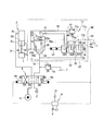
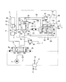
- FIG. 2 is a hydraulic circuit diagram of the fluid pressure control apparatus according to the first embodiment of the present invention.
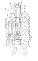
- FIG. 3 is a cross-sectional view of the load holding mechanism of the fluid pressure control apparatus according to the first embodiment of the present invention.
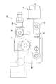
- FIG. 4 is a plan view of the load holding mechanism of the fluid pressure control apparatus according to the first embodiment of the present invention.
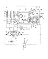
- FIG. 5 is a hydraulic circuit diagram of a fluid pressure control apparatus according to a first modification of the first embodiment of the present invention.
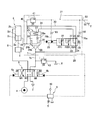
- FIG. 6 is a hydraulic circuit diagram of a fluid pressure control apparatus according to a second modification of the first embodiment of the present invention.
- FIG. 1 is a diagram showing a part of a hydraulic excavator.
- FIG. 2 is a hydraulic circuit diagram of the fluid pressure control apparatus according to the first embodiment of the present invention.
- FIG. 3 is a cross-sectional view of the load holding mechanism of the fluid pressure control apparatus according to the
- FIG. 7 is a hydraulic circuit diagram of a fluid pressure control apparatus according to a third modification of the first embodiment of the present invention.
- FIG. 8 is a hydraulic circuit diagram of a fluid pressure control apparatus according to a fourth modification of the first embodiment of the present invention.
- FIG. 9 is a hydraulic circuit diagram of the fluid pressure control apparatus according to the second embodiment of the present invention.
- FIG. 10 is a cross-sectional view of the load holding mechanism of the fluid pressure control apparatus according to the second embodiment of the present invention.
- FIG. 11 is an enlarged cross-sectional view of a portion A in FIG.
- FIG. 12 is a cross-sectional view of a load holding mechanism of a fluid pressure control device according to a fifth modification of the second embodiment of the present invention.
- FIG. 13 is a hydraulic circuit diagram of a fluid pressure control apparatus according to a sixth modification of the second embodiment of the present invention.
- FIG. 14 is a plan view of a load holding mechanism of a fluid pressure control device according to a sixth modification of the second embodiment of the present invention.
- FIG. 15 is a hydraulic circuit diagram showing a comparative example of the first embodiment of the present invention.
- FIG. 16 is a cross-sectional view showing a comparative example of the first embodiment of the present invention.
- a fluid pressure control apparatus controls the operation of a hydraulic working device such as a hydraulic excavator.
- the fluid pressure control device controls the expansion / contraction operation of the cylinder 2 that drives the arm (load) 1 of the hydraulic excavator shown in FIG.
- the hydraulic control device will be described.
- the cylinder 2 has a cylindrical cylinder tube 2c, a piston 2d that is slidably inserted into the cylinder tube 2c and divides the cylinder tube 2c into a rod side chamber 2a and an anti-rod side chamber 2b, and one end connected to the piston 2d.
- a rod 2e having the other end extending outside the cylinder tube 2c and connected to the arm 1;
- An engine is mounted on the hydraulic excavator, and a pump 4 as a fluid pressure supply source and a pilot pump 5 as a pilot pressure supply source are driven by the power of the engine.
- the hydraulic control device includes a control valve 6 that controls the supply of hydraulic oil from the pump 4 to the cylinder 2, and a pilot control valve 9 that controls the pilot pressure guided from the pilot pump 5 to the control valve 6.
- control valve 6 and the rod side chamber 2a of the cylinder 2 are connected by a first main passage 7, and the control valve 6 and the non-rod side chamber 2b of the cylinder 2 are connected by a second main passage 8.
- the control valve 6 is operated by the pilot pressure guided from the pilot pump 5 to the pilot chambers 6a and 6b through the pilot control valve 9 when the operator of the excavator manually operates the operation lever 10.
- control valve 6 has three positions: a contracted position 6A for contracting the cylinder 2, an extending position 6B for extending the cylinder 2, and a neutral position 6C for holding the load of the cylinder 2.
- the supply / discharge of the hydraulic oil is switched to control the expansion / contraction operation of the cylinder 2.
- a load holding mechanism 20 is provided in the first main passage 7 connected to the rod side chamber 2a which is a load side pressure chamber.
- the load holding mechanism 20 holds the load pressure of the rod side chamber 2a when the control valve 6 is in the neutral position 6C, and is fixed to the surface of the cylinder 2 as shown in FIG.
- the anti-rod side chamber 15b serves as a load-side pressure chamber. Therefore, when the load holding mechanism 20 is provided in the boom 14, a load is applied to the main passage connected to the anti-rod side chamber 15b. A holding mechanism 20 is provided (see FIG. 1).
- the load holding mechanism 20 operates in conjunction with the operation check valve 21 provided in the first main passage 7 and the control valve 6 by the pilot pressure guided to the pilot chamber 23 through the pilot control valve 9. And a switching valve 22 for switching the operation.
- the operation check valve 21 includes a valve body 24 for opening and closing the first main passage 7, a seat portion 28 on which the valve body 24 is seated, a back pressure chamber 25 defined on the back surface of the valve body 24, and a valve body 24.
- a passage 26 that is formed and constantly guides the hydraulic oil in the rod side chamber 2a to the back pressure chamber 25 is provided.
- the passage 26 is provided with a throttle 26a.
- the first main passage 7 includes a cylinder-side first main passage 7 a that connects the rod-side chamber 2 a and the operation check valve 21, and a control valve-side first main passage 7 b that connects the operation check valve 21 and the control valve 6. .
- the valve body 24 includes a first pressure receiving surface 24a on which the pressure of the control valve side first main passage 7b acts, and a second pressure receiving surface 24b on which the pressure of the rod side chamber 2a acts through the cylinder side first main passage 7a. It is formed.
- a spring 27 as a biasing member that biases the valve body 24 in the valve closing direction is accommodated.
- the pressure in the back pressure chamber 25 and the urging force of the spring 27 act in the direction in which the valve body 24 is seated on the seat portion 28.
- the operation check valve 21 functions as a check valve that blocks the flow of hydraulic oil from the rod side chamber 2a to the control valve 6. That is, the operation check valve 21 prevents the hydraulic oil in the rod side chamber 2a from leaking, maintains the load pressure, and maintains the arm 1 in a stopped state.
- the load holding mechanism 20 further bypasses the operating check valve 21 for the hydraulic oil in the rod side chamber 2a to the control valve side first main passage 7b, and supplies the hydraulic oil in the back pressure chamber 25 to the control valve side.
- a back pressure passage 31 that leads to the first main passage 7b.
- the switching valve 22 is provided in the bypass passage 30 and the back pressure passage 31, switches the communication of the bypass passage 30 and the back pressure passage 31 with respect to the control valve side first main passage 7b, and operates the meter-out side when the cylinder 2 is extended.
- the flow of hydraulic oil in the first main passage 7 is controlled.
- the switching valve 22 has three ports: a first supply port 32 communicating with the bypass passage 30, a second supply port 33 communicating with the back pressure passage 31, and a discharge port 34 communicating with the control valve side first main passage 7b. Have. In addition, the switching valve 22 has three positions: a cutoff position 22A, a first communication position 22B, and a second communication position 22C.
- the pilot pressure is introduced into the pilot chamber 23 to the pilot chamber 6b of the control valve 6, the pilot pressure of the same pressure is simultaneously introduced into the pilot chamber 23. That is, when the control valve 6 is switched to the extended position 6B, the switching valve 22 is also switched to the first communication position 22B or the second communication position 22C.
- the switching valve 22 maintains the cutoff position 22A by the urging force of the spring 36. At the blocking position 22A, both the first supply port 32 and the second supply port 33 are blocked.
- the switching valve 22 When the pilot pressure not lower than the first predetermined pressure and lower than the second predetermined pressure is introduced into the pilot chamber 23, the switching valve 22 is switched to the first communication position 22B.
- the first supply port 32 communicates with the discharge port 34 at the first communication position 22B.
- the hydraulic oil in the rod side chamber 2a is guided from the bypass passage 30 to the control valve side first main passage 7b through the switching valve 22. That is, the hydraulic oil in the rod side chamber 2a is guided to the control valve side first main passage 7b, bypassing the operation check valve 21.
- the throttle 37 gives resistance to the flow of hydraulic oil.
- the second supply port 33 is kept in a blocked state.
- the switching valve 22 When the pilot pressure equal to or higher than the second predetermined pressure is introduced into the pilot chamber 23, the switching valve 22 is switched to the second communication position 22C.
- the first supply port 32 communicates with the discharge port 34
- the second supply port 33 also communicates with the discharge port 34.
- the hydraulic oil in the back pressure chamber 25 is guided from the back pressure passage 31 to the control valve side first main passage 7 b through the switching valve 22.
- the hydraulic oil in the back pressure chamber 25 bypasses the throttle 37, is led to the control valve side first main passage 7 b, and is discharged from the control valve 6 to the tank T.
- a relief passage 40 is branched and connected upstream of the switching valve 22 in the bypass passage 30.
- the relief passage 40 is provided with a relief valve 41 that opens when the pressure in the rod side chamber 2a reaches a predetermined pressure, allows the hydraulic oil to pass, and releases the hydraulic oil in the rod side chamber 2a.
- the relief pressure oil (relief fluid) discharged from the relief valve 41 is discharged to the tank T through a relief discharge passage 77 connecting the relief valve 41 and the tank T.
- the relief discharge passage 77 has a main discharge passage 77a connected to the relief valve 41, and a first branch passage 77b and a second branch passage 77c branched from the main discharge passage 77a in two.
- the first branch passage 77 b is connected to the first drain port 53
- the second branch passage 77 c is connected to the second drain port 86.
- the first drain port 53 and the second drain port 86 each open to the outer surface of the body 60 described later.
- the first drain port 53 has a smaller diameter than the second drain port 86 and can be connected to a pipe having a smaller diameter.
- a pipe 55 communicating with the tank T is connected to the first drain port 53, and the second drain port 86 is sealed with a plug 88 (see FIG. 4). Therefore, in the present embodiment, the relief pressure oil discharged from the relief valve 41 is guided to the pipe 55 through the main discharge passage 77a, the first branch passage 77b, and the first drain port 53, and is discharged to the tank T.
- a relief valve 43 that opens when the pressure in the control valve side first main passage 7b reaches a predetermined pressure is connected to the control valve side first main passage 7b.
- FIG. 3 is a cross-sectional view of the load holding mechanism 20 and shows a state where the pilot pressure is not guided to the pilot chamber 23 and the switching valve 22 is in the cutoff position 22A.
- FIG. 4 is a plan view of the load holding mechanism 20. 3 and 4, the same reference numerals as those shown in FIG. 2 denote the same components as those shown in FIG.
- the switching valve 22 is incorporated in the body 60.
- a spool hole 60a is formed in the body 60, and a substantially cylindrical sleeve 61 is inserted into the spool hole 60a.
- a spool 56 is slidably incorporated in the sleeve 61.
- a spring chamber 54 is defined by a cap 57 on the side of one end surface 56 a of the spool 56.
- the spring chamber 54 is connected to the first drain passage 76 a through a notch 61 a formed in the end surface of the sleeve 61.
- the first drain passage 76 a is connected to the first branch passage 77 b of the relief discharge passage 77. Therefore, the hydraulic oil leaking into the spring chamber 54 is discharged to the tank T through the first drain passage 76a and the first branch passage 77b.
- the spring chamber 54 accommodates a spring 36 as a biasing member that biases the spool 56.
- the spring chamber 54 has an annular first spring receiving member 45 in which an end surface abuts on one end surface 56a of the spool 56 and a pin portion 56c formed to protrude from the one end surface 56a of the spool 56 is inserted into the hollow portion.
- the second spring receiving member 46 disposed near the bottom of the cap 57 are accommodated.
- the spring 36 is interposed between the first spring receiving member 45 and the second spring receiving member 46 in a compressed state, and biases the spool 56 in the valve closing direction via the first spring receiving member 45.
- the axial position of the second spring receiving member 46 in the spring chamber 54 is set by the front end portion of the adjusting bolt 47 that penetrates and is screwed into the bottom portion of the cap 57 abutting against the back surface of the second spring receiving member 46. Is done.
- the second spring receiving member 46 moves in a direction approaching the first spring receiving member 45. Therefore, the initial spring load of the spring 36 can be adjusted by adjusting the screwing amount of the adjusting bolt 47.
- the adjusting bolt 47 is fixed with a nut 48.
- the pilot chamber 23 is defined by a piston hole 60b formed in communication with the spool hole 60a and a cap 58 that closes the piston hole 60b. Pilot pressure is guided to the pilot chamber 23 through a pilot passage 52 formed in the body 60. In the pilot chamber 23, a piston 50 that receives pilot pressure on the back surface and applies thrust to the spool 56 against the urging force of the spring 36 is slidably accommodated.
- the drain chamber 51 is partitioned by the spool 56 and the piston 50 in the piston hole 60b.
- the drain chamber 51 is connected to the second drain passage 76 b, and the second drain passage 76 b is connected to the first branch passage 77 b of the relief discharge passage 77. Accordingly, the hydraulic oil leaking into the drain chamber 51 is discharged to the tank T through the second drain passage 76b and the first branch passage 77b.
- the piston 50 has a sliding portion 50a whose outer peripheral surface slides along the inner peripheral surface of the piston hole 60b, and a tip portion which is formed with a smaller diameter than the sliding portion 50a and faces the other end surface 56b of the spool 56. 50 b and a base end portion 50 c that is formed in a smaller diameter than the sliding portion 50 a and faces the tip end surface of the cap 58.
- pilot pressure oil When pilot pressure oil is supplied into the pilot chamber 23 through the pilot passage 52, pilot pressure acts on the back surface of the base end portion 50c and the annular back surface of the sliding portion 50a. As a result, the piston 50 moves forward, and the tip end portion 50 b comes into contact with the other end surface 56 b of the spool 56 to move the spool 56. As described above, the spool 56 receives the thrust of the piston 50 generated based on the pilot pressure acting on the back surface of the piston 50 and moves against the urging force of the spring 36.
- the base end portion 50c is smaller in diameter than the sliding portion 50a, and the pilot pressure is applied to the annular back surface of the sliding portion 50a. Therefore, the piston 50 can move forward.
- Each of the drain chamber 51 and the spring chamber 54 communicates with the first branch passage 77b of the relief discharge passage 77 through the first drain passage 76a and the second drain passage 76b.
- the first branch passage 77 b is formed in communication with the first drain port 53 that opens to the outer surface of the body 60.
- the first drain port 53 is connected to the tank T through a pipe 55 (see FIG. 2). Since both the drain chamber 51 and the spring chamber 54 communicate with the tank T, when the switching valve 22 is in the shut-off position 22A, atmospheric pressure acts on both ends of the spool 56, and the spool 56 moves unintentionally. Such a situation is prevented.
- the relief pressure oil discharged from the relief valve 41 and the drain in the drain chamber 51 and the spring chamber 54 join together and are discharged to the tank T through the first drain port 53 and the pipe 55.
- the spool 56 stops at a position where the biasing force of the spring 36 acting on the one end face 56 a and the thrust force of the piston 50 acting on the other end face 56 b are balanced, and the switching position of the switching valve 22 is at the stop position of the spool 56. Is set.
- the sleeve 61 includes a first supply port 32 communicating with the bypass passage 30 (see FIG. 2), a second supply port 33 communicating with the back pressure passage 31 (see FIG. 2), and the control valve side first main passage 7b. Three ports of the discharge port 34 that communicate with each other are formed.
- the outer peripheral surface of the spool 56 is partially cut out in an annular shape, and the first pressure chamber 64, the second pressure chamber 65, the third pressure chamber 66, and the cutout portion and the inner peripheral surface of the sleeve 61, A fourth pressure chamber 67 is formed.
- the first pressure chamber 64 is always in communication with the discharge port 34.
- the third pressure chamber 66 is always in communication with the first supply port 32.
- a plurality of throttles 37 communicating the third pressure chamber 66 and the second pressure chamber 65 are formed on the outer periphery of the land portion 72 of the spool 56 as the spool 56 moves against the urging force of the spring 36. .
- the fourth pressure chamber 67 is always in communication with the second pressure chamber 65 through a pressure guide passage 68 formed in the spool 56 in the axial direction.
- the poppet valve 70 moves away from the valve seat 71 and the third pressure chamber 66 and the second pressure chamber 65 communicate with each other through the plurality of throttles 37. Therefore, the first supply port 32 is connected to the third pressure chamber 66 and the second pressure chamber.
- the exhaust port 34 communicates with the chamber 65 and the first pressure chamber 64. Due to the communication between the first supply port 32 and the discharge port 34, the hydraulic oil in the rod side chamber 2 a is guided to the control valve side first main passage 7 b through the throttle 37. This state corresponds to the first communication position 22B of the switching valve 22.
- the spool 56 When the pilot pressure guided to the pilot chamber 23 increases, the spool 56 further moves against the urging force of the spring 36, and the fourth pressure chamber 67 communicates with the second supply port 33. Accordingly, the second supply port 33 communicates with the discharge port 34 through the fourth pressure chamber 67, the pressure guiding passage 68, the second pressure chamber 65, and the first pressure chamber 64.
- the hydraulic oil in the back pressure chamber 25 is guided to the control valve side first main passage 7b. This state corresponds to the second communication position 22C of the switching valve 22.
- the back pressure chamber 25 of the operation check valve 21 is maintained at the pressure of the rod side chamber 2a.
- the pressure receiving area in the valve closing direction of the valve body 24 (the area of the back surface of the valve body 24) is larger than the area of the second pressure receiving surface 24b that is the pressure receiving area in the valve opening direction. Due to the load acting on the back surface of the valve body 24 and the urging force of the spring 27, the valve body 24 is seated on the seat portion 28. In this way, the operation check valve 21 prevents the hydraulic oil in the rod side chamber 2a from leaking, and the arm 1 is kept stopped.
- the control valve 6 When the operating lever 10 is operated and the pilot pressure is guided from the pilot control valve 9 to the pilot chamber 6a of the control valve 6, the control valve 6 is switched to the contracted position 6A by an amount corresponding to the pilot pressure.
- the discharge pressure of the pump 4 acts on the first pressure receiving surface 24a of the operation check valve 21.
- the switching valve 22 since the switching valve 22 is in the cutoff position 22A without pilot pressure being guided to the pilot chamber 23, the back pressure chamber 25 of the operation check valve 21 is maintained at the pressure in the rod side chamber 2a.
- the control valve 6 When the operating lever 10 is operated and pilot pressure is guided from the pilot control valve 9 to the pilot chamber 6b of the control valve 6, the control valve 6 is switched to the extension position 6B by an amount corresponding to the pilot pressure. At the same time, since the pilot pressure is guided to the pilot chamber 23, the switching valve 22 is switched to the first communication position 22B or the second communication position 22C according to the supplied pilot pressure.
- the switching valve 22 When the pilot pressure guided to the pilot chamber 23 is equal to or higher than the first predetermined pressure and lower than the second predetermined pressure, the switching valve 22 is switched to the first communication position 22B. In this case, since the communication between the second supply port 33 and the discharge port 34 is cut off, the back pressure chamber 25 of the operation check valve 21 is maintained at the pressure of the rod side chamber 2a, and the operation check valve 21 is closed. It becomes a state.
- the switching valve 22 is switched to the first communication position 22B, for example, when carrying out a crane operation for lowering the transported object attached to the bucket 13 to the target position, or by moving the arm 1 and the boom 14 simultaneously, This is a case where a horizontal pulling operation for moving the bucket 13 horizontally is performed.
- the cylinder 2 needs to be extended at a low speed and the arm 1 needs to be slowly lowered in the direction of the arrow 81, so the control valve 6 is only slightly switched to the extended position 6B.
- the horizontal pulling operation is a difficult operation in which the arm 1 and the boom 14 are moved simultaneously so that the bucket 13 moves horizontally, the arm 1 and the boom 14 are moved slowly.
- the control valve 6 is only slightly switched to the extended position 6B. Therefore, the pilot pressure guided to the pilot chamber 6b of the control valve 6 is small, the pilot pressure guided to the pilot chamber 23 of the switching valve 22 is not less than the first predetermined pressure and less than the second predetermined pressure, and the switching valve 22 is in the first communication position. Only switch to 22B. Accordingly, the hydraulic oil in the rod side chamber 2a is discharged through the throttle 37, and the arm 1 moves at a low speed suitable for crane work and horizontal pulling work.
- the switching valve 22 when the switching valve 22 is in the first communication position 22B, even if a situation occurs such that the control valve side first main passage 7b ruptures and the hydraulic fluid leaks to the outside, it is discharged from the rod side chamber 2a. Since the flow rate of the working oil is limited by the throttle 37, the falling speed of the bucket 13 is suppressed. This function is called metering control. For this reason, before the bucket 13 falls to the ground, the switching valve 22 can be switched to the cutoff position 22A, and the sudden fall of the bucket 13 can be prevented.
- the throttle 37 is for suppressing the descending speed of the cylinder 2 when the operation check valve 21 is closed, and suppressing the falling speed of the bucket 13 when the control valve side first main passage 7b is ruptured. .
- the switching valve 22 is switched to the second communication position 22C.
- the hydraulic oil in the back pressure chamber 25 of the operation check valve 21 is guided to the control valve side first main passage 7 b through the back pressure passage 31 and is controlled. It is discharged from the valve 6 to the tank T.
- a differential pressure is generated before and after the restrictor 26a, and the pressure in the back pressure chamber 25 is reduced, so that the force in the valve closing direction acting on the valve body 24 is reduced, and the valve body 24 is separated from the seat portion 28.
- the function of the operation check valve 21 as a check valve is released.
- the operation check valve 21 allows the flow of hydraulic oil from the control valve 6 to the rod side chamber 2a, while the flow of hydraulic oil from the rod side chamber 2a to the control valve 6 according to the pressure of the back pressure chamber 25. works to allow.
- the operation check valve 21 When the operation check valve 21 is opened, the hydraulic oil in the rod side chamber 2a passes through the first main passage 7 and is discharged to the tank T, so that the cylinder 2 extends quickly. That is, when the switching valve 22 is switched to the second communication position 22C, the flow rate of the hydraulic oil discharged from the rod side chamber 2a increases, so the flow rate of the hydraulic oil supplied to the non-rod side chamber 2b increases. The elongation speed is increased. As a result, the arm 1 quickly descends in the direction of the arrow 81.
- the switching valve 22 is switched to the second communication position 22C when excavation work or the like is performed, and the control valve 6 is largely switched to the extension position 6B. For this reason, the pilot pressure led to the pilot chamber 6b of the control valve 6 is large, the pilot pressure led to the pilot chamber 23 of the switching valve 22 becomes equal to or higher than the second predetermined pressure, and the switching valve 22 switches to the second communication position 22C. .
- the relief passage 40 is provided with a relief valve 110 that opens when the pressure in the rod side chamber 2 a reaches a predetermined pressure and releases the hydraulic oil in the rod side chamber 2 a.
- An orifice 111 is provided in the relief discharge passage 77 that connects the relief valve 110 and the tank T.
- the pilot pressure is guided to the pilot chamber 23 by the operator's operation, the spool 56 is moved, and the cylinder 2 is extended, so that the pressure in the rod side chamber 2a rises and the relief valve 110 is opened.
- the relief pressure oil upstream of the orifice 111 discharged from the relief valve 110 is guided to the drain chamber 51. Since the relief back pressure upstream of the orifice 111 guided to the drain chamber 51 is larger than the pilot pressure guided to the pilot chamber 23, the piston 50 moves away from the spool 56. Therefore, the thrust of the piston 50 generated by the pilot pressure is not transmitted to the spool 56.
- the pressure receiving area of the spool 56 on which the pressure of the drain chamber 51 acts is smaller than the pressure receiving area of the piston 50, depending on the magnitude of the relief back pressure upstream of the orifice 111 guided to the drain chamber 51, the spool There is a possibility that 56 moves in the closing direction due to the urging force of the spring 36.
- the relief discharge passage 77 connecting the relief valve 41 and the tank T is not provided with an orifice. Therefore, the relief pressure oil discharged from the relief valve 41 is discharged to the tank T through the relief discharge passage 77 and no high pressure acts on the drain chamber 51.
- the spool 56 moves in the closing direction even when the relief valve 41 is opened while the operator is operating the operation lever to extend the cylinder 2. The extension speed of the cylinder 2 intended by the operator is obtained.
- the relief discharge passage 77 communicates with the second drain port 86 opened on the outer surface of the body 60 through the passage 87.
- a pipe may be connected to the second drain port 86, and the second drain port 86 and the tank T may be connected via the pipe.
- the relief pressure oil discharged from the relief valve 41 is also discharged to the tank through the passage 87, so that the flow rate of the relief pressure oil guided to the drain chamber 51 can be reduced.
- no pipes are connected to the second drain port 86, and the second drain port 86 is sealed with a plug 88 (see FIG. 4). It is preferable to do this.
- first drain port 53 is sealed with a plug, a pipe is connected to the second drain port 86, and the relief pressure oil discharged from the relief valve 41 and the drains of the drain chamber 51 and the spring chamber 54 are supplied to the second drain port 86. It may be discharged to the tank T through the drain port 86.
- the relief pressure oil discharged from the relief valve 41 joins the drains in the drain chamber 51 and the spring chamber 54 and is discharged to the tank T through the first drain port 53 and the pipe 55. Therefore, there is no need to provide a dedicated pipe for leading the relief pressure oil discharged from the relief valve 41 to the tank T, and the number of pipes can be reduced.
- the relief pressure oil discharged from the relief valve 41 is discharged to the tank T through the relief discharge passage 77 and hardly guided to the drain chamber 51, the relief back pressure pulsates when the relief valve 41 is opened. However, the pulsation is prevented from propagating to the spool 56. Therefore, the occurrence of vibration is suppressed.
- the relief valve 110 of the comparative example that switches the switching valve 22 by the discharged relief pressure oil to open the operation check valve 21 has a pressure sufficient to switch the spool 56 of the switching valve 22 to the second communication position 22C. Since it is sufficient to lead to the chamber 51, a small-capacity relief valve with a small discharge flow rate is used.
- the relief valve 41 of the present embodiment opens when the pressure in the rod side chamber 2a reaches a predetermined pressure, releases the hydraulic oil in the rod side chamber 2a to the tank T, and reduces the pressure in the rod side chamber 2a. Since it is necessary to have a function of lowering, a large-capacity relief valve having a larger discharge flow rate than the relief valve 110 of the comparative example is used.
- the relief valve 41 of this embodiment is a large capacity type
- mold the freedom degree of design improves. Further, since the relief valve 41 is a large capacity type, the pressure in the rod side chamber 2a can be kept at a predetermined pressure even when a surge pressure is generated such that the pressure in the rod side chamber 2a suddenly increases. Therefore, it is possible to prevent the cylinder 2 from being damaged by the surge pressure.
- the method of connecting the first drain passage 76a and the second drain passage 76b to the relief discharge passage 77 is different from the embodiment shown in FIGS.
- the connection method of the 1st drain path 76a and the 2nd drain path 76b with respect to the relief discharge path 77 is not limited to a specific structure.
- an orifice 84 is provided as a throttle that provides resistance to the passing hydraulic oil in a merged drain passage 76 c where the first drain passage 76 a and the second drain passage 76 b merge.
- the relief pressure oil discharged from the relief valve 41 is discharged to the tank T through the relief discharge passage 77, and a high pressure hardly acts on the drain chamber 51. That is, in the first embodiment, even if the relief valve 41 is opened, the operation of the switching valve 22 is not affected, and the relief pressure oil discharged from the relief valve 41 does not operate the switching valve 22.
- the hydraulic control apparatus has a load as shown in FIG.
- the holding mechanism 20 includes a connection passage 78 that connects the pilot chamber 23 and the drain chamber 51, and a check valve 90 that is provided in the connection passage 78 and allows only hydraulic oil to pass from the drain chamber 51 to the pilot chamber 23. Also have.
- the hydraulic control apparatus according to the second embodiment will be specifically described.
- connection passage 78 that connects the drain chamber 51 and the pilot chamber 23 is provided in the piston 50.
- the connection passage 78 is provided with a check valve 90 that allows only the flow of hydraulic oil from the drain chamber 51 to the pilot chamber 23.
- the piston 50 is formed so that the pressure receiving area that receives the pressure of the drain chamber 51 is equal to the pressure receiving area that receives the pressure of the pilot chamber 23.
- connection passage 78 is formed so as to open to both end surfaces in the axial direction at the axial center position of the piston 50.
- the check valve 90 includes a ball 91 that is attached to and detached from a valve seat 78a formed in the connection passage 78, and a cap member 92 that is provided on the opposite side of the valve seat 78a with the ball 91 interposed therebetween.
- the cap member 92 includes a through hole 93 that penetrates in the axial direction, and a slit 94 that extends in the radial direction on the end surface on the ball 91 side (right side in FIG. 11) so as to communicate with the through hole 93.
- the check valve 90 When the pressure in the pilot chamber 23 is higher than the pressure in the drain chamber 51, the check valve 90 is closed. Specifically, the ball 91 is seated on the valve seat 78a, and the communication between the drain chamber 51 and the pilot chamber 23 is blocked.
- the check valve 90 opens (state shown in FIG. 11). Specifically, the ball 91 is separated from the valve seat 78 a and comes into contact with the end surface of the cap member 92, and the hydraulic oil in the drain chamber 51 is guided to the pilot chamber 23 through the slit 94 and the through hole 93. By opening the check valve 90 in this way, the drain chamber 51 and the pilot chamber 23 communicate with each other through the connection passage 78.
- the check valve 90 has a structure that does not include a biasing member (for example, a spring) that biases the ball 91, but is not limited to this, and the ball 91 is biased by the biasing member. May be.
- the check valve 90 is not limited to the structure shown in FIG.
- the relief pressure oil discharged from the relief valve 41 is discharged to the tank T through the relief discharge passage 77 as in the first embodiment.
- the drain chamber 51 and the pilot chamber 23 are connected by a connection passage 78 formed in the piston 50.
- the check valve 90 is opened by the relief pressure oil, and at the same time, the pilot chamber 23 Relief pressure oil is also introduced. Since the pressure receiving area of the piston 50 that receives the pressure of the drain chamber 51 and the pressure receiving area of the piston 50 that receives the pressure of the pilot chamber 23 are substantially equal to each other, the thrust acting on the piston 50 by the relief pressure oil cancels each other.
- the relief valve 41 is opened while the operator is operating the operating lever to extend the cylinder 2, and the relief pressure oil whose pressure is higher than the pilot pressure is introduced to the drain chamber 51.
- the piston 50 is not moved by the relief pressure oil. That is, the spool 56 does not move in the closing direction by the relief fluid, and the switching valve 22 does not operate.
- the spool 56 moves in the closing direction. The expansion / contraction speed of the cylinder 2 intended by the operator can be obtained more reliably.
- the relief pressure oil discharged from the relief valve 41 is discharged to the tank T through the relief discharge passage 77, the relief fluid does not operate the switching valve 22. Further, since the pilot chamber 23 and the drain chamber 51 are connected by the connection passage 78, even if the relief pressure oil is guided to the drain chamber 51 through the relief discharge passage 77 and the drain passage 76 b, the pilot chamber is simultaneously connected through the connection passage 78. Relief pressure oil is also led to 23. As a result, the thrusts acting on the piston 50 by the relief pressure oil cancel each other, so that even if the relief pressure oil is guided to the switching valve, the switching valve 22 does not operate.
- a connecting passage 78 that connects the drain chamber 51 and the pilot chamber 23 is formed in the piston 50. For this reason, processing of the connection passage 78 is facilitated, and space efficiency can be improved.
- connection passage 78 that connects the drain chamber 51 and the pilot chamber 23 is formed in the piston.
- the pilot line includes a pilot passage 52 and a pilot chamber 23.
- the return line includes a relief discharge passage 77, first and second drain passages 76a. 76b and a drain chamber 51 are included. This will be specifically described below.
- connection passage 78 is formed in the body 60 and connects the pilot passage 52 and the second drain passage 76b. Even in the fifth modified example, when the relief valve 41 is opened, the relief pressure oil is guided to the drain chamber 51 through the second drain passage 76b, and at the same time, the second drain passage 76b and the connection passage 78 are provided. And through the pilot passage 52 to the pilot chamber 23. Therefore, according to the 5th modification, there exists an effect similar to the said 2nd Embodiment.
- a pipe 55 is connected to the first drain port 53, and the first drain port 53 and the tank T are connected via the pipe 55.
- the first drain port 53 may be sealed with a plug
- the pipe 55a may be connected to the second drain port 86
- the second drain port 86 and the tank T may be connected via the pipe 55a.
- connection passage 78 may be formed in the body 60 to connect the second branch passage 77 c and the pilot passage 52.
- the pipe 55 a connected to the second drain port 86 can be connected to a pipe having a larger diameter than the pipe 55 connected to the first drain port 53.
- the cost increases by connecting the pipe 55a having a relatively large diameter the flow resistance can be reduced and the relief pressure guided to the drain chamber 51 can be reduced. Thereby, the movement of the spool 56 by relief pressure oil can be prevented more reliably.
- piping may be connected to both the 1st drain port 53 and the 2nd drain port 86, and relief pressure oil may be discharged
- the connection passage 78 may be connected to the first branch passage 77b or may be connected to the second branch passage 77c. According to this, the flow rate of the relief pressure oil guided to the drain chamber 51 can be reduced.
- no pipe is connected to the second drain port 86 and the second drain port 86 is plugged 88 as in the above embodiment. It is preferable to seal with.
- connection passage that connects any one of the main discharge passage 77a, the first branch passage 77b, and the first drain passage 76a in the relief discharge passage 77 and any one of the pilot chamber 23 and the pilot passage 52 is provided. It may be provided.
- connection passage 78 includes the pilot passage 52 and the pilot chamber 23 that constitute the pilot line, the relief discharge passage 77 that constitutes the return line, the first and second drain passages 76a and 76b, and the drain chamber. Any one of 51 may be connected.
- the piston 50 Since the piston 50 is small compared to the body 60, it is easy to process. Conventionally, no other oil passages are formed in the piston 50 and space efficiency can be improved. It is preferable to form the piston 50 as in the embodiment.
- each configuration according to the first to fourth modifications of the first embodiment may be employed in the fluid pressure control device according to the second embodiment.
- the fluid pressure control device that controls the expansion and contraction operation of the cylinder 2 that drives the arm 1 includes the control valve 6 that controls the supply of hydraulic oil from the pump 4 to the cylinder 2, and the pilot pump 5.
- the operation check valve 21 that allows the flow of hydraulic oil from the rod side pressure chamber 2a to the control valve 6 and the pilot pressure guided through the pilot control valve 9 are interlocked with the control valve 6.
- a relief discharge passage 77 that leads the tank T to the tank T.
- the switching valve 22 includes a pilot chamber 23 through which pilot pressure is guided through the pilot control valve 9, a spool 56 that moves according to the pilot pressure in the pilot chamber 23, and a spool A spring chamber 54 in which a spring 36 for urging the valve 56 in the valve closing direction is accommodated; a piston 50 for receiving a pilot pressure on the back surface and applying a thrust force against the urging force of the spring 36 to the spool 56; 50, the drain chamber 51, the drain chamber 51, and the spring chamber 54 are connected to the relief discharge passage 77. And a drain passage 76a, 76b to the relief pressure oil discharged from the relief valve 41 is discharged to the tank T not operate the switching valve 22 through the relief discharge passage 77.
- the relief pressure oil discharged from the relief valve 41 is discharged to the tank T through the relief discharge passage 77 and does not operate the switching valve 22. Therefore, the operator operates the operation lever so that the cylinder 2 is expanded and contracted. Even when the relief valve 41 is opened during the operation, the spool 56 does not move in the closing direction, and the expansion / contraction speed of the cylinder 2 intended by the operator can be obtained. Therefore, stable operation of the cylinder 2 is possible.
- the drain passages 76a and 76b are provided with throttles 82 and 83 for imparting resistance to the passing hydraulic oil.
- the relief valve 41 has a larger discharge flow rate compared to the case where the operation check valve 21 is opened by switching the switching valve 22 by the discharged relief pressure oil.
- a pilot line is constituted by the pilot passage 52 and the pilot chamber 23, and a return line is constituted by the relief discharge passage 77, the drain chamber 51, and the first and second drain passages 76a and 76b.
- the holding mechanism 20 further includes a connection passage 78 that connects the pilot line and the return line, and a check valve 90 that is provided in the connection passage 78 and allows only hydraulic oil to pass from the return line to the pilot line.
- the relief pressure oil discharged from the relief valve 41 is discharged to the tank T through the relief discharge passage 77, so that the relief pressure oil does not operate the switching valve 22.
- the pilot line and the return line communicate with each other through the connection passage 78, even if the relief pressure oil is guided to the drain chamber 51 of the switching valve 22 through the relief discharge passage 77 and the drain passage 76 b, the pilot line and the return line are simultaneously piloted through the connection passage 78.
- Relief pressure oil is also introduced into the chamber 23. As a result, the thrusts acting on the piston 50 by the relief pressure oil cancel each other, so that the relief pressure oil does not affect the operation of the switching valve 22.
- connection passage 78 is formed in the piston 50 and connects the drain chamber 51 and the pilot chamber 23.
- connection passage 78 the processing of the connection passage 78 is facilitated, and the space efficiency can be improved.
- connection passage 78 may connect the relief discharge passage 77 and the pilot passage 52.
- connection passage 78 may connect the drain passage 76b and the pilot passage 52.
Landscapes
- Engineering & Computer Science (AREA)
- General Engineering & Computer Science (AREA)
- Physics & Mathematics (AREA)
- Fluid Mechanics (AREA)
- Mechanical Engineering (AREA)
- Mining & Mineral Resources (AREA)
- Civil Engineering (AREA)
- Structural Engineering (AREA)
- Fluid-Pressure Circuits (AREA)
- Operation Control Of Excavators (AREA)
Priority Applications (4)
| Application Number | Priority Date | Filing Date | Title |
|---|---|---|---|
| KR1020187008794A KR20180056665A (ko) | 2015-09-25 | 2016-09-21 | 유체압 제어 장치 |
| EP16848612.4A EP3354905B1 (de) | 2015-09-25 | 2016-09-21 | Fluiddrucksteuerungsvorrichtung |
| US15/762,641 US20180282974A1 (en) | 2015-09-25 | 2016-09-21 | Fluid pressure control device |
| CN201680056517.XA CN108138809B (zh) | 2015-09-25 | 2016-09-21 | 流体压控制装置 |
Applications Claiming Priority (4)
| Application Number | Priority Date | Filing Date | Title |
|---|---|---|---|
| JP2015-188453 | 2015-09-25 | ||
| JP2015188453A JP6502813B2 (ja) | 2015-09-25 | 2015-09-25 | 流体圧制御装置 |
| JP2016153158A JP6706170B2 (ja) | 2016-08-03 | 2016-08-03 | 流体圧制御装置 |
| JP2016-153158 | 2016-08-03 |
Publications (1)
| Publication Number | Publication Date |
|---|---|
| WO2017051824A1 true WO2017051824A1 (ja) | 2017-03-30 |
Family
ID=58386637
Family Applications (1)
| Application Number | Title | Priority Date | Filing Date |
|---|---|---|---|
| PCT/JP2016/077842 WO2017051824A1 (ja) | 2015-09-25 | 2016-09-21 | 流体圧制御装置 |
Country Status (5)
| Country | Link |
|---|---|
| US (1) | US20180282974A1 (de) |
| EP (1) | EP3354905B1 (de) |
| KR (1) | KR20180056665A (de) |
| CN (1) | CN108138809B (de) |
| WO (1) | WO2017051824A1 (de) |
Cited By (2)
| Publication number | Priority date | Publication date | Assignee | Title |
|---|---|---|---|---|
| WO2023017719A1 (ja) * | 2021-08-10 | 2023-02-16 | Kyb株式会社 | 流体圧制御装置 |
| US11753801B2 (en) * | 2018-12-13 | 2023-09-12 | Kawasaki Jukogyo Kabushiki Kaisha | Hydraulic drive system |
Families Citing this family (6)
| Publication number | Priority date | Publication date | Assignee | Title |
|---|---|---|---|---|
| JP7211687B2 (ja) * | 2018-10-17 | 2023-01-24 | キャタピラー エス エー アール エル | 降下防止弁装置、ブレード装置および作業機械 |
| JP6960585B2 (ja) * | 2018-12-03 | 2021-11-05 | Smc株式会社 | 流量コントローラ及びそれを備えた駆動装置 |
| US10947996B2 (en) * | 2019-01-16 | 2021-03-16 | Husco International, Inc. | Systems and methods for selective enablement of hydraulic operation |
| CN110230617B (zh) * | 2019-06-24 | 2020-04-07 | 徐州阿马凯液压技术有限公司 | 一种新型负载保持阀 |
| CA3140348A1 (en) * | 2020-11-24 | 2022-05-24 | Wilian Holding Co. | Detachable body securing mechanism and associated systems and methods |
| CN115506444B (zh) * | 2022-09-29 | 2023-06-16 | 山东临工工程机械有限公司 | 挖掘机液压系统及挖掘机 |
Citations (2)
| Publication number | Priority date | Publication date | Assignee | Title |
|---|---|---|---|---|
| JP2004084727A (ja) * | 2002-08-23 | 2004-03-18 | Shin Caterpillar Mitsubishi Ltd | 回路装置および作業機械 |
| JP2013204603A (ja) * | 2012-03-27 | 2013-10-07 | Kyb Co Ltd | 流体圧制御装置 |
Family Cites Families (5)
| Publication number | Priority date | Publication date | Assignee | Title |
|---|---|---|---|---|
| JPH07127607A (ja) * | 1993-09-07 | 1995-05-16 | Yutani Heavy Ind Ltd | 作業機械の油圧装置 |
| JP3919399B2 (ja) * | 1998-11-25 | 2007-05-23 | カヤバ工業株式会社 | 油圧制御回路 |
| DE102005022275A1 (de) * | 2004-07-22 | 2006-02-16 | Bosch Rexroth Aktiengesellschaft | Hydraulische Steueranordnung |
| CN101230870A (zh) * | 2008-02-19 | 2008-07-30 | 湖南三一起重机械有限公司 | 起重机执行机构流量控制模块 |
| CN102852186B (zh) * | 2012-09-27 | 2014-10-22 | 太原重工股份有限公司 | 一种用于防止液压挖掘机动臂意外下落的液压装置 |
-
2016
- 2016-09-21 CN CN201680056517.XA patent/CN108138809B/zh active Active
- 2016-09-21 KR KR1020187008794A patent/KR20180056665A/ko unknown
- 2016-09-21 WO PCT/JP2016/077842 patent/WO2017051824A1/ja active Application Filing
- 2016-09-21 US US15/762,641 patent/US20180282974A1/en not_active Abandoned
- 2016-09-21 EP EP16848612.4A patent/EP3354905B1/de active Active
Patent Citations (2)
| Publication number | Priority date | Publication date | Assignee | Title |
|---|---|---|---|---|
| JP2004084727A (ja) * | 2002-08-23 | 2004-03-18 | Shin Caterpillar Mitsubishi Ltd | 回路装置および作業機械 |
| JP2013204603A (ja) * | 2012-03-27 | 2013-10-07 | Kyb Co Ltd | 流体圧制御装置 |
Cited By (2)
| Publication number | Priority date | Publication date | Assignee | Title |
|---|---|---|---|---|
| US11753801B2 (en) * | 2018-12-13 | 2023-09-12 | Kawasaki Jukogyo Kabushiki Kaisha | Hydraulic drive system |
| WO2023017719A1 (ja) * | 2021-08-10 | 2023-02-16 | Kyb株式会社 | 流体圧制御装置 |
Also Published As
| Publication number | Publication date |
|---|---|
| CN108138809A (zh) | 2018-06-08 |
| EP3354905A4 (de) | 2019-06-05 |
| EP3354905B1 (de) | 2020-09-02 |
| KR20180056665A (ko) | 2018-05-29 |
| CN108138809B (zh) | 2020-02-07 |
| EP3354905A1 (de) | 2018-08-01 |
| US20180282974A1 (en) | 2018-10-04 |
Similar Documents
| Publication | Publication Date | Title |
|---|---|---|
| WO2017051824A1 (ja) | 流体圧制御装置 | |
| JP5948260B2 (ja) | 流体圧制御装置 | |
| JP5822233B2 (ja) | 流体圧制御装置 | |
| JP6159629B2 (ja) | 流体圧制御装置 | |
| US10132059B2 (en) | Fluid pressure control device | |
| KR102372065B1 (ko) | 유체압 제어 장치 | |
| JP6706170B2 (ja) | 流体圧制御装置 | |
| JP4918001B2 (ja) | 流体圧制御装置 | |
| JP6857571B2 (ja) | 流体圧制御装置 | |
| JP2002106507A (ja) | 液圧アクチュエータの流量制御装置 | |
| JP6502813B2 (ja) | 流体圧制御装置 | |
| JP5184299B2 (ja) | 流体圧制御装置 | |
| KR101844170B1 (ko) | 건설 기계의 유체압 제어 장치 | |
| JP2004132411A (ja) | 油圧制御装置 | |
| WO2023017719A1 (ja) | 流体圧制御装置 | |
| WO2023176685A1 (ja) | 流体圧制御装置 | |
| WO2023176686A1 (ja) | 流体圧制御装置 | |
| WO2015174250A1 (ja) | 流体圧制御装置 | |
| JP2012197909A (ja) | 流体圧制御装置 | |
| KR20200047934A (ko) | 외부 작업기 구동을 위한 작동유 취출 유압회로 |
Legal Events
| Date | Code | Title | Description |
|---|---|---|---|
| 121 | Ep: the epo has been informed by wipo that ep was designated in this application |
Ref document number: 16848612 Country of ref document: EP Kind code of ref document: A1 |
|
| WWE | Wipo information: entry into national phase |
Ref document number: 15762641 Country of ref document: US |
|
| NENP | Non-entry into the national phase |
Ref country code: DE |
|
| ENP | Entry into the national phase |
Ref document number: 20187008794 Country of ref document: KR Kind code of ref document: A |
|
| WWE | Wipo information: entry into national phase |
Ref document number: 2016848612 Country of ref document: EP |