WO2017051773A1 - 透析用容器 - Google Patents
透析用容器 Download PDFInfo
- Publication number
- WO2017051773A1 WO2017051773A1 PCT/JP2016/077413 JP2016077413W WO2017051773A1 WO 2017051773 A1 WO2017051773 A1 WO 2017051773A1 JP 2016077413 W JP2016077413 W JP 2016077413W WO 2017051773 A1 WO2017051773 A1 WO 2017051773A1
- Authority
- WO
- WIPO (PCT)
- Prior art keywords
- dialysis
- container
- core member
- peripheral wall
- bottle
- Prior art date
- Legal status (The legal status is an assumption and is not a legal conclusion. Google has not performed a legal analysis and makes no representation as to the accuracy of the status listed.)
- Ceased
Links
Images










Classifications
-
- A—HUMAN NECESSITIES
- A61—MEDICAL OR VETERINARY SCIENCE; HYGIENE
- A61J—CONTAINERS SPECIALLY ADAPTED FOR MEDICAL OR PHARMACEUTICAL PURPOSES; DEVICES OR METHODS SPECIALLY ADAPTED FOR BRINGING PHARMACEUTICAL PRODUCTS INTO PARTICULAR PHYSICAL OR ADMINISTERING FORMS; DEVICES FOR ADMINISTERING FOOD OR MEDICINES ORALLY; BABY COMFORTERS; DEVICES FOR RECEIVING SPITTLE
- A61J1/00—Containers specially adapted for medical or pharmaceutical purposes
- A61J1/05—Containers specially adapted for medical or pharmaceutical purposes for collecting, storing or administering blood, plasma or medical fluids ; Infusion or perfusion containers
- A61J1/10—Bag-type containers
-
- A—HUMAN NECESSITIES
- A61—MEDICAL OR VETERINARY SCIENCE; HYGIENE
- A61J—CONTAINERS SPECIALLY ADAPTED FOR MEDICAL OR PHARMACEUTICAL PURPOSES; DEVICES OR METHODS SPECIALLY ADAPTED FOR BRINGING PHARMACEUTICAL PRODUCTS INTO PARTICULAR PHYSICAL OR ADMINISTERING FORMS; DEVICES FOR ADMINISTERING FOOD OR MEDICINES ORALLY; BABY COMFORTERS; DEVICES FOR RECEIVING SPITTLE
- A61J1/00—Containers specially adapted for medical or pharmaceutical purposes
- A61J1/14—Details; Accessories therefor
-
- A—HUMAN NECESSITIES
- A61—MEDICAL OR VETERINARY SCIENCE; HYGIENE
- A61M—DEVICES FOR INTRODUCING MEDIA INTO, OR ONTO, THE BODY; DEVICES FOR TRANSDUCING BODY MEDIA OR FOR TAKING MEDIA FROM THE BODY; DEVICES FOR PRODUCING OR ENDING SLEEP OR STUPOR
- A61M1/00—Suction or pumping devices for medical purposes; Devices for carrying-off, for treatment of, or for carrying-over, body-liquids; Drainage systems
- A61M1/14—Dialysis systems; Artificial kidneys; Blood oxygenators ; Reciprocating systems for treatment of body fluids, e.g. single needle systems for hemofiltration or pheresis
- A61M1/16—Dialysis systems; Artificial kidneys; Blood oxygenators ; Reciprocating systems for treatment of body fluids, e.g. single needle systems for hemofiltration or pheresis with membranes
Definitions
- the present invention relates to a dialysis container that is attached to a dialysis machine and contains a dialysis agent for preparing a dialysis solution.
- dialysis containers have been used to accommodate and provide solid dialysis agents in artificial dialysis.
- a dialysis container a hard resin container is used as described in Japanese Patent Application Laid-Open No. 2001-340447 (Patent Document 1).
- the dialysis agent is dissolved in the solution by allowing it to flow inside, and a dialysis solution is prepared and supplied.
- the conventional dialysis container made of a hard resin as described in Patent Document 1 is bulky to keep its original shape even after the dialysis agent is almost empty after dialysis. There was a problem that it was difficult to dispose of.
- Patent Document 2 JP-A-2006-136615 (Patent Document 2), a dialysis container comprising a flexible sheet bag is proposed.
- the dialysis container disclosed in Patent Document 2 has two flexible sheets stacked on the front and back of a hollow structure penetrating member and welded to the periphery. An outlet is formed. Since the bag itself made of a flexible sheet has substantially no strength, it is designed to ensure the stability when it is attached to the dialysis machine with a penetrating member, and a hollow cylindrical structure penetrating member is adopted. Thus, inflow and outflow of the solution are allowed, and a communication hole is provided in the peripheral wall of the penetrating member, thereby realizing dissolution of the dialysis agent in the bag.
- the bag described in Patent Document 2 cannot be kept in a fixed shape because it is made of a flexible sheet. Therefore, the operation of injecting and filling the dialysis agent is difficult.
- the penetrating member Because of the existence, it is difficult to inflate the flexible bag to secure the volume.
- the bag body is not formed in a constant shape even when the dialysis agent is accommodated, it is difficult to accurately check (check) the filling amount (internal volume) in the bag. In addition, it may be deformed unexpectedly while being used in a dialysis machine.
- the present invention has been made in the background as described above, and a problem to be solved thereof is a dialysis container that accommodates a dialysis agent and is provided to a dialysis site.
- the volume can be reduced upon disposal after use, it can be disposed of efficiently, and the filling of the dialysis agent is facilitated. It is an object of the present invention to provide a dialysis container having a novel structure that can be easily confirmed.
- a first aspect of the present invention is a dialysis container in which an inflow port and an outflow port are provided on opposite sides to accommodate a dialysis agent, and has a hollow structure with a peripheral wall portion formed integrally with the dialysis container.
- a bottle-shaped container that is held in a substantially constant shape before and after the dialysis agent is accommodated and has deformation rigidity that is crushed by atmospheric pressure exerted on the outer peripheral surface of the peripheral wall portion by internal pressure reduction is adopted.
- the bottle-shaped container is provided with an inner core member that is spanned between the opposing both sides provided with the outlet.
- the dialysis container having the structure according to this aspect since the inner core member is provided between the opposing sides with the inflow / outflow port, the inflow / outflow port of the dialysis container is attached to the dialysis device. Even if an external force such as compression is applied in the direction, the risk of the dialysis container being crushed in the direction is reduced, and the mounting state on the dialysis apparatus can be stably maintained.
- a dialysis container In general, in a dialysis container, deionized water is added from the inflow port, and the dissolved solution is discharged from the outflow port while dissolving the dialysis agent. The inside of the dialysis container is depressurized.
- the dialysis container of this embodiment since it is crushed by the atmospheric pressure exerted on the outer peripheral surface due to internal decompression, the dialysis container is automatically crushed as the solution is discharged, and after use, the dialysis container When discarding the dialysis container, it can be prevented from being bulky, and operations such as crushing the dialysis container can be omitted.
- the shape does not change greatly before and after the dialysis agent is accommodated. Therefore, compared to the dialysis container having the bag structure described in Patent Document 2, for example, the dialysis container Therefore, the storage volume is sufficiently secured even before the dialysis agent is stored, and the dialysis agent can be easily filled. In addition, since the shape of the dialysis container is substantially constant even after the dialysis agent is accommodated, it is easy to check the filling amount of the dialysis agent.
- the bottle-shaped container is integrally formed with an inclined peripheral wall portion that narrows at both side opening portions of the cylindrical peripheral wall portion. And the inflow port and the outflow port are provided at the tip of each inclined peripheral wall portion.
- both the end surfaces of the cylindrical peripheral wall portion are flat surfaces extending in the direction perpendicular to the axis.
- peripheral portion of the outlet is an inclined peripheral wall portion
- the possibility that the dialysis agent solution remains in the dialysis container can be reduced.
- the inclined peripheral wall portion on the outlet side for example, by providing the same shape of the inclined peripheral wall portion on both the inlet side and the outlet side
- the dialysis container can be provided. Since it is not necessary to determine the direction of the inflow port and the outflow port when mounting on the dialyzer, the mounting can be made easier.
- the wall thickness of the inclined peripheral wall portion provided with the inflow port and the outflow port is larger than that of the cylindrical peripheral wall portion. It has been enlarged.
- the volume reduction deformation of the cylindrical peripheral wall portion during decompression is allowed relatively easily, and excessive deformation in the vicinity of the inlet and the outlet is suppressed.
- the connection state of the inlet and outlet to the dialyzer can be more stably ensured.
- the container for dialysis of this aspect can be suitably formed, for example by blow molding.
- the cylindrical peripheral wall portion has a non-cylindrical cross-sectional shape having a flat plate portion at least partially. It is what.
- the cylindrical peripheral wall portion is more easily deformed and deformed during decompression than when the cylindrical peripheral wall portion is cylindrical.
- the cylindrical peripheral wall has a flat shape compared to a cylindrical shape in which the stress generated during the action of the pressure difference between the inside and outside of the cylindrical peripheral wall is mainly stress in the compression direction, Since the stress is positively generated, the thickness of the cylindrical peripheral wall portion can be easily crushed by the internal / external pressure difference while sufficiently securing the thickness according to various conditions such as molding and strength.
- a fifth aspect of the present invention is the dialysis container according to any one of the first to fourth aspects, wherein the bottle-shaped container is provided with a groove-shaped deformation control section.
- transformation control part may be formed, for example by providing a ditch
- a sixth aspect of the present invention is the dialysis container according to any one of the first to fifth aspects, wherein the center member is attached to the inlet and the outlet of the bottle-shaped container. At least one of them has a structure opened to the outer periphery without having an annular peripheral wall continuous in the circumferential direction.
- the core member is attached to the inlet and outlet of the bottle-shaped container, at least a part of the core member is opened to the outer periphery.
- a dialysis agent, deionized water, or the like can be easily filled into the bottle-shaped container through the opening.
- at least one end of the core member is open to the outer periphery, when inserting an injection nozzle such as a dialysis agent or deionized water into the end of the core member.
- the end portion of the core member is easily bent and deformed, and the insertion resistance of the injection nozzle can be reduced.
- the dialysis container according to the sixth aspect wherein the core member is at least partly in the length direction, and a part of the circumference is opened to the outer periphery.
- the cross section extends in the length direction.
- An eighth aspect of the present invention is the dialysis container according to the sixth or seventh aspect, wherein the core member is opened to the outer periphery at a plurality of locations on the circumference in at least a part of the length direction.
- a radial reinforcing portion extending in the longitudinal direction with a radial cross section composed of a plurality of circumferential upper portions divided in the circumferential direction and a connecting portion extending in the radial direction from the central portion and connecting the circumferential upper portions to each other. It is what.
- a ninth aspect of the present invention is the dialysis container according to any one of the sixth to eighth aspects, wherein both end portions in the length direction of the core member are opened to the outer periphery at a part of the circumference. While the circular arc cross section extends in the length direction, the intermediate member in the length direction of the core member extends in the length direction with a radial cross section protruding from the center portion to the outer peripheral side.
- the structure of the core member can be simplified because the core member extends in the length direction with a predetermined cross-sectional shape.
- a C-shaped cross section extending more than half a circumference is suitable, and when such a C-shaped cross section or the radial cross section of the eighth or ninth aspect is adopted, the core member
- the sectional moment of inertia can be set large while keeping the sectional area of the core small, and the bending rigidity of the core member can be more efficiently ensured.
- the maximum width dimension in the middle portion in the length direction of the core member is the length of the core member. It is made smaller than the maximum width dimension in the direction both ends.
- the maximum width dimension of the lengthwise both ends of the core member is secured to some extent, so that both end portions on the inlet side and the outlet side in the dialysis container It is also possible to ensure sufficient rigidity. Therefore, the dialysis container can be more stably attached to the dialysis apparatus. Further, since the maximum width dimension of the intermediate portion in the length direction of the core member is reduced, the possibility that the volume reduction deformation of the dialysis container is hindered by the core member can be reduced. Therefore, the volume of the dialysis container can be reduced more stably.
- a reinforcing rib is provided on the core member.
- the bending rigidity of the core member can be secured stably.
- the shape of the reinforcing rib can be designed and changed according to the shape of the core member, and the degree of freedom in setting the bending rigidity of the core member can be improved.
- the hinge member having a lower bending strength than the other part at the intermediate portion in the longitudinal direction of the core member.
- the part is provided.
- the hinge part having a smaller bending strength than the other part is provided in the intermediate part in the longitudinal direction of the core member, It is also possible to easily remove the dialysis container from the dialysis apparatus and bend it after the solution of the agent flows out and the volume of the dialysis container is reduced. Thereby, the container for dialysis can be crushed smaller and discarded.
- a thirteenth aspect of the present invention is the dialysis container according to any one of the first to twelfth aspects, wherein the bottle-shaped container is a separate body at least one of the inlet and the outlet in a blow molded product. The formed mouth member is fixed.
- the thickness of the cylindrical peripheral wall portion can be made substantially constant over substantially the whole.
- the volume reduction deformation at the time of decompression can be stably realized without accompanying local deformation at an unexpected location.
- the dialysis container having a structure according to the present invention since the core member is provided inside the bottle-shaped container, the dialysis container can be stably attached to the dialysis apparatus by the reinforcing effect of the core member. Further, since the inside is crushed by reducing the pressure, it is possible to automatically reduce the volume after discharging the dialysis agent solution and dispose of it without being bulky. Furthermore, unlike a bag-like dialysis container having a conventional structure, since it is a bottle-shaped container, filling of the dialysis agent and confirmation of the filling amount can be easily performed.
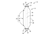
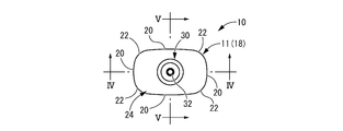
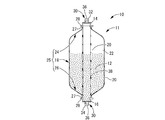
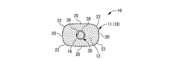
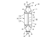
- the side view of the container for dialysis shown by FIG. The top view of the container for dialysis shown by FIG. IV-IV sectional drawing in FIG. VV sectional drawing in FIG. VI-VI sectional drawing in FIG.
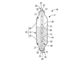
- the side view of the container for dialysis shown by FIG. It is a longitudinal cross-sectional view of the dialysis container as the third embodiment of the present invention, and corresponds to FIG. It is another longitudinal cross-sectional view of the dialysis container shown by FIG. 9, Comprising: The figure corresponding to FIG. FIG.
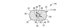
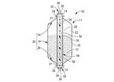
- FIG. 10 is a cross-sectional view of the dialysis container shown in FIG. 9, corresponding to FIG. 6. It is a longitudinal cross-sectional view of the container for dialysis as the 4th Embodiment of this invention, Comprising: The figure corresponding to FIG. It is another longitudinal cross-sectional view of the dialysis container shown by FIG. 12, Comprising: The figure corresponding to FIG. FIG. 13 is a transverse cross-sectional view of the dialysis container shown in FIG. 12, corresponding to FIG. 6. It is a figure which shows another aspect of the core member which comprises the container for dialysis of this invention, Comprising: (a) is a top view, (b) is a longitudinal cross-sectional view.
- FIG. 19 is a left side view of the dialysis container shown in FIG. 18, corresponding to FIG. 2.
- FIG. 19 is an enlarged cross-sectional view showing a section XXII-XXII in FIG.
- FIG. 19 is a cross-sectional view showing an enlarged XXIII-XIII cross section in FIG. 18. It is a longitudinal cross-sectional view of the dialysis container as the sixth embodiment of the present invention, and corresponds to FIG.
- FIGS. 1 to 6 show a dialysis container 10 as a first embodiment of the present invention.
- the dialysis container 10 includes a bottle-shaped container 11 extending substantially linearly, and a dialysis agent 12 is accommodated therein. And the both ends of the length direction (up-down direction in FIG. 1) of this dialysis container 10 are attached to a dialysis machine (not shown).
- deionized water is supplied into the dialysis container 10 from the dialysis apparatus through the inlet 14 of the dialysis container 10 to dissolve the dialysis agent 12, and the dissolved solution flows into the dialysis container 10. It is discharged to the dialysis machine through the outlet 16.
- this solution is mixed with another solution separately prepared in a dialysis machine, so that it is prepared as a dialysate and used for artificial dialysis.
- the vertical direction refers to the vertical direction in FIG.
- the bottle-shaped container 11 has a hollow thin cylindrical shape extending in the vertical direction as a whole, and a middle portion in the length direction is a cylindrical peripheral wall portion 18 extending straight in the vertical direction.
- the cylindrical peripheral wall portion 18 has a non-cylindrical cross section.
- the cylindrical peripheral wall portion 18 has a rounded rectangular shape as shown in FIG. That is, the cylindrical peripheral wall portion 18 is configured by flat plate portions 20, 20, 20, 20 that extend in parallel with the length direction in four directions (up and down, left and right directions in FIG. 6). , 20 are smoothly connected by the curved portions 22, 22, 22, 22.
- upper and lower inclined peripheral wall portions 24 and 26 projecting in the vertical direction are integrally formed at the upper and lower openings of the cylindrical peripheral wall portion 18.
- the peripheral wall portion 25 of the bottle-shaped container 11 is constituted by the cylindrical peripheral wall portion 18 and the upper and lower inclined peripheral wall portions 24 and 26.
- These upper and lower inclined peripheral wall portions 24 and 26 have substantially the same tapered cylindrical shape, and the respective large-diameter side opening portions are smoothly connected to the upper and lower opening portions of the cylindrical peripheral wall portion 18.
- the upper and lower inclined peripheral wall portions 24 and 26 project in a funnel shape narrowing toward the inner peripheral side as they become outward in the length direction, and circular inlets are respectively provided at the protruding ends on the small diameter side. 14 and the outlet 16 are open.
- the inflow port 14 and the outflow port 16 are provided in the both sides which oppose on the central axis of the bottle-shaped container 11, and are each extended on the central axis. And the internal space enclosed by the surrounding wall part 25 of the bottle-shaped container 11 is connected outside by the inflow port 14 and the outflow port 16.
- the small diameter cylindrical portions 27 and 27 protrude straight from the protruding tips of the upper and lower inclined peripheral wall portions 24 and 26 with a predetermined length outward in the longitudinal direction, and the openings of the small diameter cylindrical portions 27 and 27 are open.
- Flange-like portions 28, 28 are provided.
- the bottle-shaped container 11 is integrally formed by, for example, blow molding using a soft synthetic resin.
- the soft synthetic resin include polyethylene chloride, polypropylene, polyvinyl chloride, polyethylene terephthalate (PET), and the like.
- PET polyethylene terephthalate
- polypropylene is adopted.
- the thickness of the upper and lower inclined peripheral walls 24 and 26 is made larger than the thickness of the cylindrical peripheral wall 18.
- caps 30 and 30 as mouth members are attached to the flange-like portions 28 and 28 in the upper and lower inclined peripheral wall portions 24 and 26, respectively.
- Each of the caps 30 and 30 has a substantially stepped cylindrical shape, and the inner holes of the caps 30 and 30 are aligned with the inlet 14 and the outlet 16.
- the large diameter side cylinder part of the caps 30 and 30 is piled up on the flange-like parts 28 and 28 of the up-and-down inclination surrounding wall parts 24 and 26, and is fixed by adhesion
- both caps 30 and 30 protrudes outward in the length direction, and the end of the cap 30 protruding upward is the inflow side port 32, while the end of the cap 30 protruding downward Is the outflow side port 34.
- filters 36 and 36 are fixed inside the caps 30 and 30, respectively.
- the filters 36 and 36 are configured such that the dialysis agent 12 prior to dissolution cannot pass through, while the deionized water or a solution obtained by dissolving the dialysis agent 12 can pass therethrough.
- the caps 30 and 30 are formed by injection molding using a hard synthetic resin, for example, and are formed separately from the bottle-shaped container 11.
- the deformation rigidity of these caps 30 and 30 is not particularly limited, but the dialysis container 10 can be stably attached to the dialysis apparatus by making it larger than the deformation rigidity of the bottle-shaped container 11 described later.
- a core member 38 is stretched between the upper and lower inclined peripheral wall portions 24 and 26.
- the core member 38 is attached so as to extend linearly in the vertical direction from the inlet 14 which is the upper end of the upper inclined peripheral wall portion 24 to the outlet 16 which is the lower end of the lower inclined peripheral wall portion 26. It has been.
- the core member 38 has a substantially C-shaped cross section, and the core member 38 has an arc cross section in which a part of the circumference is opened to the outer periphery. At least a part of the length direction, in this embodiment, the entire length direction. In short, in this embodiment, the core member 38 does not have an annular peripheral wall continuous in the circumferential direction or a solid part in any part in the length direction, and a part of the circumference is the outer periphery. Open to.
- the circumferential direction dimension of this core member 38 is not specifically limited, It is suitable to have the circumferential direction dimension more than a half circumference.
- the cross-sectional secondary moment can be set large while keeping the cross-sectional area of the core member 38 small, and the bending rigidity of the core member 38 can be efficiently ensured.
- the maximum width dimension of the core member 38 is the small diameter cylindrical portion 27 provided on the upper and lower inclined peripheral wall portions 24, 26. 27, and the inner peripheral surface of the small-diameter cylindrical portions 27 and 27 and the outer peripheral surface of the core member 38 are fixed to each other, so that the core member 38 is connected to the inlet 14 and the flow path. Attached to the outlet 16.
- the material of the core member 38 is not limited in any way, but can be suitably formed by, for example, injection molding of a hard synthetic resin.
- hard synthetic resins include polyethylene, polypropylene, polycarbonate, and acrylonitrile-butadiene-styrene copolymer synthetic resin (ABS resin).
- ABS resin acrylonitrile-butadiene-styrene copolymer synthetic resin
- high-density polyethylene is employed.
- the rigidity of the core member 38 is not limited in any way, but is preferably larger than the deformation rigidity of the bottle-shaped container 11 described later.
- a dialysis agent 12 is accommodated in the dialysis container 10 having the shape as described above.
- the lower opening of the bottle-like container 11 is closed by the cap 30 and the dialysis agent 12 is used for injecting the dialysis agent 12 into the inlet 14 (the core member 38) that is the upper opening of the bottle-like container 11. It is injected by inserting a nozzle.
- the core member 38 of the present embodiment has a structure in which a part of the circumference is opened to the outer circumference, the dialysis agent 12 is introduced into the bottle-shaped container 11 through the opening on the circumference. Easily injected.
- pouring of the dialysis agent 12 the dialysis agent 12 is accommodated in the inside of the dialysis container 10 because the upper opening of the bottle-shaped container 11 is obstruct
- the dialysis agent 12 accommodated in the dialysis container 10 is not particularly limited, sodium hydrogen carbonate is employed in the present embodiment.
- the dialysis container 10 having such a structure is mounted so as to be sandwiched and compressed with respect to the dialysis apparatus from above and below.
- the deionized water supply section provided in the dialysis apparatus is connected to the inflow side port 32 of the dialysis container 10
- the solution discharge section provided in the dialysis apparatus is connected to the outflow side port 34 of the dialysis container 10.
- the deionized water supplied from the dialysis machine is introduced into the dialysis container 10 through the inflow port 32 and the inflow port 14 to dissolve the dialysis agent 12 accommodated in the dialysis container 10.
- the solution of the dialysis agent 12 is sent to the dialysis machine through the outlet 16 and the outlet port 34.
- the deformation rigidity of the bottle-shaped container 11 is substantially unchanged before and after the dialysis agent 12 is accommodated, and the dialysis agent 12 in the dialysis container 10 is dissolved in deionized water.
- the pressure in the bottle-shaped container 11 is reduced, the bottle-shaped container 11 is crushed by the difference between the pressure in the bottle-shaped container 11 and the atmospheric pressure exerted on the outer peripheral surface 39 of the bottle-shaped container 11. Is set.
- a negative pressure of 10 mmHg is used so that the volume can be efficiently crushed and reduced by the reduced pressure exerted inside the bottle-shaped container 11.
- Those having a volume reduction rate of 5% or more are preferred, and those having a volume reduction rate of 10% or more at a negative pressure of 10 mmHg are more preferred.
- the bottle-shaped container 11 is collapsed by an external force during transportation or mounting to the dialysis apparatus, or when the dialysis container 10 is removed from the dialysis apparatus and released into the atmosphere after the solution of the dialysis agent 12 is discharged.
- the shape may be restored to some extent by an elastic restoring action, it is preferable that the bottle-shaped container 11 of the present invention maintains a reduced volume state even when it is opened to the atmosphere. For example, when the internal volume of the bottle-shaped container 11 is reduced to 50% or less due to internal decompression, the volume reduction state is maintained so that the volume is not recovered to 80% even if the interior is subsequently opened to the atmosphere. Those are preferred.
- the dialysis container 10 having the above structure is mounted so as to be sandwiched and compressed with respect to the dialysis apparatus in the vertical direction.
- the dialysis container 10 is provided with the core member 38 extending in the vertical direction, when the dialysis container 10 is attached to the dialysis device due to the reinforcing effect of the core member 38, The possibility that the dialysis container 10 is compressed and deformed in the vertical direction can be effectively reduced.
- the caps 30 and 30 of upper and lower ends and the dialysis apparatus can be connected stably, and a mounting state can be maintained stably.
- the bottle-shaped container 11 has a deformation rigidity that allows the shape of the bottle-shaped container 11 to be maintained substantially constant before and after the dialysis agent 12 is accommodated, for example, the bag-shaped dialysis described in Patent Document 2 described above. It is not necessary to maintain the opening area by holding the opening in an open state as compared with the container for use, and the dialysis agent 12 can be easily filled. Furthermore, since the shape of the dialysis agent 12 does not change when the dialysis agent 12 is filled as compared with the bag-like dialysis container, the filling amount of the dialysis agent 12 can be easily confirmed.
- the bottle-shaped container 11 has a deformation rigidity such that when the dialysis agent 12 inside is dissolved in deionized water and discharged, the inside is decompressed and collapsed due to the difference from the external atmospheric pressure. Yes. Thereby, after discharging
- the peripheral wall portion 25 of the bottle-shaped container 11 is configured to include the upper and lower inclined peripheral wall portions 24 and 26, the bottle-shaped container 11 can have a sufficient volume and the bottle-shaped container 11. Even when a reduced pressure is applied, the volume of the bottle-like container 11 can be easily reduced by changing the inclination angle of the upper and lower inclined peripheral wall portions 24 and 26. Further, since the lower side of the peripheral wall portion 25 is an inclined peripheral wall portion 26 and the outflow port 16 is provided at the projecting tip portion of the inclined peripheral wall portion 26, the dissolved solution remains inside the bottle-shaped container 11. It can be discharged efficiently without any problems.
- the dialysis apparatus can be mounted without distinction between the upper and lower sides, and work efficiency can be improved. Can be achieved.
- the cross section of the cylindrical surrounding wall part 18 is made into the rounded rectangular shape and has the flat plate-shaped parts 20, 20, 20, 20, 20, at the time of pressure reduction, for example, it becomes a cylindrical cross-sectional shape.
- shearing and bending direction stress are easily generated, and a more efficient volume reduction effect can be achieved.
- the plate thickness dimension can be made substantially constant, and the bottle-shaped container 11 is locally unexpected at the time of decompression. Deformation can be effectively prevented.
- the upper and lower inclined peripheral wall portions 24 and 26 on the outlet side are located on the upper side or the lower side of the cylindrical peripheral wall portion 18 that is an intermediate portion. The one is made thicker. In this way, the cylindrical peripheral wall 18 is thinner than the upper and lower inclined peripheral walls 24 and 26, so that the volumetric deformation of the cylindrical peripheral wall 18 is relatively easy to occur during decompression. The volume reduction efficiency can be improved.
- the core member 38 of the present embodiment has an arc cross section in which a part of the circumference is opened to the outer circumference, and extends along the entire length in the length direction with the arc cross section. Therefore, for example, when the dialysis agent 12 is filled, when the injection nozzle is inserted into the end of the core member 38, the core member 38 is easily bent and deformed, and the injection nozzle can be easily inserted. Is done.
- FIGS. 7 and 8 show a dialysis container 40 as a second embodiment of the present invention.
- a groove-shaped deformation control unit 42 is provided on the outer peripheral surface 39 of the bottle-shaped container 11.
- members and parts that are substantially the same as those of the first embodiment are denoted by the same reference numerals as those of the first embodiment in the drawings, and detailed description thereof is omitted. .
- a plurality of deformation control units 42 of the present embodiment are provided on the outer peripheral surface 39 of the bottle-shaped container 11, and as shown in FIGS. 7 and 8, extend in the circumferential direction of the bottle-shaped container 11 and in the vertical direction.
- a groove, a groove extending along the curved portions of the upper and lower inclined peripheral wall portions 24 and 26, and the like are provided at predetermined positions.
- the deformation control unit 42 according to the present embodiment is formed by providing the outer circumferential surface 39 of the bottle-shaped container 11 with a groove having a substantially semicircular cross section and providing a ridge with a substantially semicircular cross section on the inner circumferential surface.
- the thickness dimension of the bottle-shaped container 11 where the deformation control unit 42 is formed is substantially equal to the thickness dimension of the part where the deformation control unit 42 is not formed.
- the formation location of the deformation control unit 42 is preferentially crushed. It has become.
- the shape after volume reduction of the dialysis container 40 is controlled.
- the shape, size, number, etc. of the deformation control unit 42 are set so that the volume after volume reduction is further reduced.
- the container 40 can be disposed of more efficiently without being bulky.
- the deformation control unit may be any unit that controls the shape of the bottle-shaped container 11 after the deformation due to the decompression action.
- the outer peripheral surface 39 may be provided with a concave groove and the inner peripheral surface may be provided with a ridge, or the outer peripheral surface 39 or the inner peripheral surface may be provided with a convex portion to be relatively concave. You may make it form.
- a spiral groove or the like can be adopted in addition to a linearly or annularly extending groove.
- the groove cross section need not be semicircular, and various shapes such as a polygonal shape such as a triangle can be adopted.
- FIGS. 9 to 11 show a dialysis container 44 as a third embodiment of the present invention.
- the core member 46 of the present embodiment is different in shape from the core member 38 of the first embodiment.
- the core member 46 has a radial cross section composed of a pair of peripheral upper portions 48, 48 and a pair of connecting portions 50, 50, and extends over at least a part in the length direction, in this embodiment, the entire length in the length direction. It is extended and formed.
- These circumferential upper portions 48 and 48 are opposed to each other in the radial direction (left-right direction in FIG. 11) with a predetermined circumferential dimension.
- the cylindrical member is provided in the circumferential direction by providing openings on the both sides in the vertical direction of FIG. 11 with predetermined circumferential dimensions and extending over the entire length in the axial direction.
- a pair of peripheral upper portions 48 and 48 are formed by being divided.
- the connecting portions 50 and 50 respectively extend from the circumferential central portion of the circumferential upper portions 48 and 48 toward the central direction, and are connected to each other at the central portion.
- the connecting portions 50, 50 extend in the radial direction from the central portion and are connected to the peripheral upper portions 48, 48, and the pair of peripheral upper portions 48, 48 are connected to each other by the connecting portions 50, 50.
- a radial cross section shown in FIG. 11 or the like is constituted by the circumferential upper portions 48 and 48 and the connecting portions 50 and 50, and the radial reinforcing section is formed by extending the radial cross section in the length direction. That is, in this embodiment, the core member 46 is a radial reinforcing portion over the entire length.
- the core member 46 As in the present embodiment, excellent bending rigidity can be ensured while keeping the cross-sectional area of the core member 46 small. Accordingly, it is possible to secure a more stable storage area for the dialysis agent 12 in the bottle-shaped container 11.
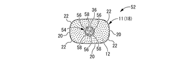
- FIGS. 12 to 14 show a dialysis container 52 as a fourth embodiment of the present invention.
- the core member 54 of the present embodiment has a radial cross section extending over the entire length in the length direction, and the entire core member 54 is a radial reinforcing portion.
- circumferential upper portions 56, 56, 56 are provided at three positions on the circumference at equal intervals, and connecting portions from the circumferential central portion of each circumferential upper portion 56, 56, 56 toward the center. 58, 58, 58 extends, and the connecting portions 58, 58, 58 are connected to each other at the central portion.
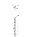
- 15 to 17 show core members 60, 62, and 64 that can be applied to the dialysis container of the present invention.
- the core member 60 shown in FIG. 15 includes an arc-shaped portion 66 that is substantially C-shaped or substantially U-shaped in plan view, and a bottom wall portion 68 that the arc-shaped portion 66 is curved, It is comprised by the side wall parts 70 and 70 which protrude from each of the circumferential direction both ends of the wall part 68. As shown in FIG. A substantially semicircular reinforcing rib 72 protrudes from the inner peripheral surface of the bottom wall portion 68.
- the core member 60 is configured by extending the entire length in the longitudinal direction with such a cross-sectional shape.
- a plurality of notches 74 are provided at substantially equal intervals in the vertical direction in the side wall portions 70, 70, and the side walls 70 in each of the plurality of notches 74. , 70 are formed on the inner peripheral side of the reinforcing ribs 76, 76. These reinforcing ribs 76 and 76 protrude to the inner peripheral side at a protruding height that does not reach the central reinforcing rib 72, and the reinforcing ribs 76 and 76 face each other with a gap in the vertical direction in FIG. Yes.
- the core member 64 shown in FIG. 17 includes the reinforcing ribs 78 having a shape such that the reinforcing ribs 76 and 76 in FIG. 16 are connected to each other, that is, provided on the side wall portions 70 and 70.
- substantially semicircular reinforcing ribs 78 project so as to fill the inner peripheral side of the arcuate portion 66.
- any of the reinforcing ribs 72, 76, 78, etc. shown in FIGS. 15 to 17 can be appropriately employed depending on the required deformation rigidity of the core member, and by providing the reinforcing rib on the core member, The degree of freedom in setting the deformation rigidity in the core member can be improved.
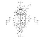
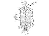
- FIGS. 18 to 23 show a dialysis container 80 as a fifth embodiment of the present invention.
- a groove-shaped deformation control unit 42 is provided on the outer peripheral surface 39 of the bottle-shaped container 11 as in the second embodiment, while the shape of the core member 82 is the same as that described above. It is different from the one described in the embodiment.
- the center core member 82 of the present embodiment has a maximum width dimension at the middle portion in the vertical direction that is smaller than the maximum width dimension at both ends in the vertical direction.
- both end portions in the vertical direction of the core member 82 have a substantially C-shaped arc cross section, and have a predetermined length in the vertical direction.
- the widened portions 84 and 84 are formed with openings 86 and 86 in a part of the circumference (downward in FIGS. 22 and 23), and the openings 86 and 86 are opened to the outer peripheral side.
- the widened portions 84 and 84 are formed with a circumferential dimension of more than half a circumference.
- the maximum width dimension (the lateral dimension in FIG. 18) on the inner surface of the widened portions 84, 84 is substantially equal to the inner diameter dimension of the large-diameter side cylindrical portion of the cap 30, 30.
- the inner surface and the inner surfaces of the caps 30 and 30 are smoothly connected.
- the maximum width dimension on the outer surface of the widened portions 84 and 84 is made smaller than the inner diameter dimension of the small diameter cylindrical portions 27 and 27 provided on the upper and lower inclined peripheral wall portions 24 and 26. Therefore, the outer peripheral surfaces of both end portions (widened portions 84, 84) in the vertical direction of the core member 82 are not fixed to the inner peripheral surfaces of the small diameter cylindrical portions 27, 27, and the core member 82 is a bottle-shaped container. 11 is not fixed.
- the core member 82 is fixed to the large-diameter side cylindrical portion of the caps 30, 30 so as to be fixed in the bottle-shaped container 11 via the caps 30, 30, or the caps 30, 30. It is made into the state fixed in the bottle-shaped container 11 by being pinched between the up-down directions.
- an intermediate portion in the vertical direction of the core member 82 is a narrow width portion 88 whose maximum width dimension is smaller than the maximum width dimension of the wide width portions 84 and 84.
- the narrow width portion 88 has a substantially cross-shaped cross section as a whole. That is, four projecting portions 90, 90, 90, 90 projecting outward from the center portion in the vertical and horizontal directions in FIG. 23 are provided.
- the projecting portions 90, 90, 90, 90 are provided at substantially equal intervals in the circumferential direction, and by these projecting portions 90, the intermediate portion in the longitudinal direction of the core member 82 is moved from the central portion to the outer peripheral side.
- a protruding radial cross section is formed. And these each protrusion part 90 is extended in the up-down direction between the wide parts 84 and 84 with the said radial cross section.
- the narrow width portion 88 and the wide width portions 84 and 84 are formed substantially concentrically, and the protruding height from the center of the protruding portion 90 (the width dimension of the protruding portion 90) is larger than the radius of curvature of the wide width portions 84 and 84.
- the maximum width dimension of the narrow width portion 88 (approximately twice the width dimension of the protruding portion 90) is made smaller than the maximum width dimension on the inner surfaces of the wide width portions 84 and 84.
- the narrow portion 88 is provided with a plurality of reinforcing ribs 92 that are spaced apart in the vertical direction.
- the three reinforcing ribs 92, 92, and 92 are arranged in the vertical direction in the narrow width portion 88. It is formed at substantially equal intervals.
- the reinforcing rib 92 is formed so as to connect the projecting portions 90 adjacent to each other in the circumferential direction with a substantially triangular shape. As shown in FIG. 22, the reinforcing rib 92 has a narrow width at the position where the reinforcing rib 92 is formed.
- the part 88 has a substantially square cross section.
- a reinforcing rib 94 is formed at the connecting portion between the narrow width portion 88 and the wide width portions 84 and 84, thereby improving the strength. That is, on both the upper and lower end surfaces of the narrow width portion 88, plate-like reinforcements that mutually connect the narrow width portion 88 and the inner surfaces of the wide width portions 84, 84 in a part of the circumference (left side in FIG. 21). Ribs 94a and 94a are formed. These reinforcing ribs 94a and 94a have a substantially triangular shape as shown in FIG. 21, and connect the projecting portion 90 located on the left side in FIG. 21 and the inner surfaces of the widened portions 84 and 84. It is provided to do.
- the outer surface of the narrow width portion 88 and the upper and lower portions of the wide width portions 84 and 84 are partly on the circumference (both sides in the left-right direction in FIG. 20 and the left side in FIG. 21).
- Plate-shaped reinforcing ribs 94b are formed to connect the direction ends to each other. As shown in FIG. 20 and the like, these reinforcing ribs 94b are provided with curved surfaces that gradually spread on the outer peripheral side as it goes outward in the vertical direction, and the outer surface of the narrow portion 88 and the wide portions 84, 84 are provided. The vertical end is smoothly connected.
- these reinforcing ribs 94 b are provided with protrusions 90 and 90 located on the left and right sides of FIG. 20 and a protrusion 90 and a widening part located on the left side of FIG. 21.
- 84 and 84 are provided so as to be connected to the vertical ends.
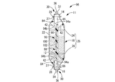
- the maximum width dimension of the intermediate part in the vertical direction is made smaller than the maximum width dimension of the both ends in the vertical direction (widened parts 84, 84) of the core member 82. Therefore, when the dialysis agent 12 is dissolved and discharged, the dialysis container 80 can be reduced in volume and deformed to a smaller extent.
- wide portions 84, 84 having large width dimensions are formed at both ends in the vertical direction of the core member 82, so that the rigidity of both ends in the vertical direction of the core member 82 is sufficiently secured, and dialysis is performed.
- the dialysis container 80 can be stably attached to the apparatus.
- the injection nozzle is stably inserted into the widened portions 84, 84.
- the widened portions 84 and 84 have an arcuate cross-sectional shape having openings 86 and 86, the widened portions 84 and 84 can be easily bent and deformed when the injection nozzle is inserted.
- FIG. 24 shows a dialysis container 96 as a sixth embodiment of the present invention.
- the core member 98 in the present embodiment as a whole has the same structure as the core member 82 in the fifth embodiment, but in the middle portion in the vertical direction of the core member 98 than the other portions.
- a hinge portion 100 having a bending strength reduced by reducing the cross-sectional area is provided.
- a notch 102 that opens to the right in FIG. 24 is formed in the narrow width portion 88 of the core member 98.
- This notch 102 is formed in, for example, a triangular cross section, and extends from the right end portion in FIG. 24 to the middle portion of the protruding portion 90 located on the left side in FIG. Further, the notch 102 extends over the entire length of both projecting portions 90, 90 also in the direction orthogonal to the plane of the drawing (the front and back direction) in FIG. Thereby, in the protrusion part 90 located in the left in FIG. 24, the part which opposes the notch 102 in the left-right direction in FIG. 24 is made thin, and the core member 98 can be bent with the thin part.
- the hinge part 100 by which bending strength was made smaller than the other part by this thin part is comprised.
- the notch 102 has a triangular cross section, but the thickness dimension (vertical dimension) of the notch 102 may be substantially 0 and may be slit-shaped, or may be in the width direction (see FIG.
- a notch from both sides or a notch from the outer periphery to the inner periphery may be employed over the entire circumference.
- the hinge part 100 having a small bending strength is formed in the middle part of the center member 98 in the vertical direction.
- the core member 98 can be easily detached from the dialyzer and bent. Thereby, the dialysis container 96 can be further crushed and discarded.
- this hinge part 100 may be provided in the formation position of the wide part 84 and the reinforcement ribs 92, 94a, and 94b instead of or in addition to the narrow part 88.
- a blow-molded product of a bottle-shaped container that has a structure according to the second embodiment and can be suitably employed as a dialysis container of the present invention was actually manufactured, and the amount of collapse in the dialysis container during decompression was measured.
- polyethylene was used as the material of the bottle-shaped container, and containers having a container weight (not including a cap and a core member) of 25 g, 29 g, 33 g, and 39 g were produced.
- the volume of each dialysis container was 760 mL.
- the thickness of each container was measured with a dial gauge for the container weights of 25 g and 33 g.
- a dial gauge for the container weights of 25 g and 33 g.
- the thickness was about 1500 to 1900 ⁇ m.
- a dialysis container having a container weight of 33 g approximately 1300 to 1600 ⁇ m in the vicinity of the upper flange-shaped portion (small-diameter cylindrical portion), and approximately in the central portion (flat plate-shaped portion) of the cylindrical peripheral wall portion in the front view and the rear view.
- the thickness dimension of the peripheral wall portion 25 is preferably about 250 to 1200 ⁇ m.
- the crushed amount was measured by reducing the pressure inside each prototype dialysis container.
- caps were welded to the upper and lower ends of the bottle-shaped container, and a vacuum pump and a pressure gauge were connected to one port (for example, the upper inflow side port).
- a syringe was connected to the other port (for example, the lower outflow side port) using a tube and a three-way stopcock so that water could be injected while maintaining airtightness.
- the vacuum pump was operated to reduce the pressure until the inside of the dialysis container had a predetermined negative pressure.
- the three-way cock was operated while keeping airtight, and the dialysis container was filled with water until the dialysis container returned to its original shape.
- the water in the dialysis container is transferred to the graduated cylinder, and the amount of water required for the dialysis container to return to its original shape is crushed when the dialysis container is decompressed. Measured as a quantity.
- the value of the amount of crushing is expressed in mL, and the value in parentheses is a percentage with respect to the total amount (760 mL).
- the bottle weight is 25 g and 29 g, measurement was not performed when a negative pressure of 30 mmHg was exerted, but when the bottle weight was 25 g, the negative pressure of 10 mmHg and 20 mmHg was exerted. It is estimated that the same result is obtained when a negative pressure of 30 mmHg is applied. Moreover, it is estimated that the result when a negative pressure of 30 mmHg is exerted on a bottle having a weight of 29 g will be larger than that when a negative pressure of 20 mmHg is exerted.
- the core members 38, 46, 54, 60, 62, 64, 82, and 98 extend in the vertical direction. It is sufficient that the reinforcing effect is exerted when the dialysis container is mounted on the dialysis apparatus, for example, even if it is entirely or partially inclined or curved in the vertical direction.
- the cross-sectional shape may be partially different, which makes it easier to bend the core member after removing the dialysis container from the dialysis machine, for example. Thus, the volume at the time of disposal can be further reduced.
- size, etc. should be set suitably so that it may suit a dialysis apparatus. Can do.
- the cylindrical peripheral wall portion 18 has a substantially rounded rectangular shape (non-cylindrical shape), and the flat plate-like portions 20, 20, 20, 20 are provided on four sides of the cylindrical peripheral wall portion 18.
- a flat plate portion is provided on at least a part of the cylindrical peripheral wall portion, volume reduction deformation can easily occur in the flat plate portion.
- the cylindrical peripheral wall portion preferably has a flat cross-sectional shape such as an ellipse, a rounded rectangle, or a rectangle rather than a cross-sectional shape that is rotationally symmetric with respect to a center such as a circle or square.
- the flat part 20 was provided in the cylindrical surrounding wall part 18, the part which is easy to be crushed in the circumferential direction was formed,
- transformation control part 42 as described in the said 2nd Embodiment is provided.
- a portion that is easily crushed in the circumferential direction for example, it may have a rotationally symmetric shape such as a circular cross-sectional shape.
- the bottle-like container is provided with such a portion that is easily crushed, but the portion that is easily crushed is not provided, so that the atmospheric pressure is uniformly applied to the entire outer peripheral surface during decompression. Good.
- the upper and lower ends of the peripheral wall portion 25 are inclined peripheral wall portions 24 and 26 that incline in the length direction, respectively, but plate-like wall portions that extend in the direction orthogonal to the length direction. It may be said. Furthermore, in the said embodiment, although the cylindrical surrounding wall part 18 extended straightly in the up-down direction, the taper cylinder shape etc. which become a small diameter gradually toward the downward direction as a whole etc. may be sufficient, for example.
- the core members 38, 46, 54, 60, 62, 64, 82, 98 are portions opened to the outer periphery over the entire length in the length direction.
- the core member may have a partially annular structure or a solid structure in the length direction, and the cross-sectional shape may change in the length direction. In short, it is only necessary that the flow of the liquid is prevented by providing the core member and closing the inlet and the outlet.
- the circumferential upper portions 48 and 56 constituting the radial cross section are arcuate, but it is not necessary to do so, and may be linear, for example.
- the connecting portion does not need to be linear, and may be curved or bent.
- the direction extending from the central portion is two directions of the third embodiment, three directions of the fourth embodiment, and four directions of the fifth embodiment.
- the connecting portion and the protruding portion may extend from the central portion in five or more directions.
- a connection part and a protrusion part may be provided in the circumferential direction at substantially equal intervals, it is not limited to this aspect.
- the shape of the reinforcing rib provided on the core member is not limited to the fifth and sixth embodiments and the modes described in FIGS. 15 to 17, but the length direction and the circumferential direction of the core member, You may extend in various directions, such as a spiral direction.
- the reinforcing rib may be manufactured separately from the core member and fixed to the core member, but may be integrally formed, for example, by partially thickening the core member. Good.
- the hinge portion 100 (notch 102) provided in the sixth embodiment is the center member 38, 46, 54 in the first to fourth embodiments or the middle member shown in FIGS.
- the core members 60, 62, and 64 may be provided.
- one hinge part 100 (notch 102) is provided, but a plurality of hinge parts (notches) are separated from each other in the length direction of the core member. It may be provided.
- the notch for forming the hinge part may be formed inclined with respect to the horizontal direction.
- the bottle-shaped container does not need to be formed by blow molding.
- an opening is provided in the bottom wall, or an overall cylindrical bottle shape having both side openings.
- the container may be integrally formed.
- caps 30 and 30 of the separate body were attached to the up-down direction both ends of the bottle-shaped container 11, these caps 30 and 30 are not essential, for example, a cap is not provided but bottle shape. It may be directly attached to the dialysis apparatus at the small-diameter cylindrical portion which is the upper and lower ends of the container, or the bottle-shaped container may be integrally formed including the structural part of the cap.
Landscapes
- Health & Medical Sciences (AREA)
- Veterinary Medicine (AREA)
- Public Health (AREA)
- General Health & Medical Sciences (AREA)
- Animal Behavior & Ethology (AREA)
- Life Sciences & Earth Sciences (AREA)
- Hematology (AREA)
- Heart & Thoracic Surgery (AREA)
- Urology & Nephrology (AREA)
- Pharmacology & Pharmacy (AREA)
- Biomedical Technology (AREA)
- Anesthesiology (AREA)
- Engineering & Computer Science (AREA)
- Vascular Medicine (AREA)
- Emergency Medicine (AREA)
- External Artificial Organs (AREA)
- Medical Preparation Storing Or Oral Administration Devices (AREA)
Abstract
透析用剤を収容して透析現場へ提供される透析用容器であって、透析装置へ安定して装着可能であると共に、使用後の廃棄に際して減容することができて効率的に処分可能であり、且つ、透析用剤の充填が容易とされて、透析用剤の充填量の確認も容易に行うことが可能とされる、新規な構造の透析用容器を提供する。 流入口14と流出口16が対向する両側に設けられて透析用剤12を収容する透析用容器10において、一体形成された周壁部25を備えた中空構造とされると共に、透析用剤12の収容前後で実質的に一定形状に保持され且つ内部減圧により周壁部25の外周面39に及ぼされる大気圧で潰れる変形剛性を備えたボトル状容器11を採用し、流入口14と流出口16が設けられた対向する両側間に掛け渡される中芯部材38をボトル状容器11の内部に設けた。
Description
本発明は、透析装置に装着されて、透析液を調製するための透析用剤を収容する透析用容器に関するものである。
従来から、人工透析において固体型の透析用剤を収容して提供するのに透析用容器が用いられている。かかる透析用容器としては、特開2001-340447号公報(特許文献1)に記載されているように硬質の樹脂容器が用いられており、透析現場で透析装置に装着して溶解用溶液を容器内に流通させることで透析用剤を溶液に溶解させ、透析液を調製して供給するようになっている。
ところで、特許文献1に記載の如き硬質樹脂製とされた従来構造の透析用容器は、透析によって透析用剤が使用されて殆ど空になった後でも原形を保つために嵩ばってしまい、廃棄処分しづらいという問題があった。
そこで、特開2006-136615号公報(特許文献2)において、可撓性シートの袋体からなる透析用容器が提案されている。特許文献2に開示された透析用容器は、中空構造の貫通部材の周囲に表裏2枚の可撓性シートを重ね合わせて周囲を溶着すると共に、貫通部材の両端外周に密着させて流入口と流出口を形成したものである。可撓性シートからなる袋体自体が実質的に強度を持たないことから、透析装置への装着時の安定性を貫通部材で確保するようにされており、且つ中空筒構造の貫通部材を採用することで、溶液の流入と流出を許容すると共に、貫通部材の周壁に連通孔を設けることで袋内の透析用剤の溶解を実現している。
しかしながら、特許文献2に記載の袋体では、可撓性シートからなるが故に袋体自体が一定形状を保ち得ない。そのために、透析用剤の注入充填の作業が難しく、特に特許文献2の実施形態に記載されているように2枚の可撓性シートを密着状態で重ね合わせた袋体構造では、貫通部材の存在故に可撓性袋体を膨らませて容積を確保することも難しい。また、透析用剤の収容状態でも袋体が一定形状とされないが故に、袋内充填量(内容量)を精度良く確認(チェック)することも難しいという問題があった。しかも、透析装置に装着しての使用中に予期せずに変形してしまうことがあり、そのために、例えば容器内圧力を測定して管理や制御などを行う透析装置では正確な容器内圧力の測定自体が難しいという問題もあった。さらに、透析用容器には、溶液の流通や排出に際して所定の耐圧性能が要求されることから、薄肉の可撓性シートでは、それらを相互に固着したり、流入および流出用の口部において硬質の貫通部材の周囲へ固着するのに、流体密性と耐圧性を十分な信頼性をもって確保することも難しかった。事実、このような多くの問題を内在しているが故に、実用化が難しく、特許文献2に記載の袋状の容器は市場に提供されていないのが現状である。
ここにおいて、本発明は上述の如き事情を背景としてなされたものであって、その解決課題とするところは、透析用剤を収容して透析現場へ提供される透析用容器であって、透析装置へ安定して装着可能であると共に、使用後の廃棄に際して減容することができて効率的に処分可能であり、且つ、透析用剤の充填が容易とされて、透析用剤の充填量の確認も容易に行うことが可能とされる、新規な構造の透析用容器を提供することにある。
以下、このような課題を解決するために為された本発明の態様を記載する。なお、以下に記載の各態様において採用される構成要素は、可能な限り任意の組み合わせで採用可能である。また、本発明の態様乃至は技術的特徴は、以下に記載のものに限定されることなく、明細書全体および図面に記載され、或いはそれらの記載から当業者が把握することの出来る発明思想に基づいて認識されるものであることが理解されるべきである。
本発明の第1の態様は、流入口と流出口が対向する両側に設けられて透析用剤を収容する透析用容器において、一体形成された周壁部を備えた中空構造とされると共に、前記透析用剤の収容前後で実質的に一定形状に保持され且つ内部減圧により該周壁部の外周面に及ぼされる大気圧で潰れる変形剛性を備えたボトル状容器を採用し、前記流入口と前記流出口が設けられた前記対向する両側間に掛け渡される中芯部材を該ボトル状容器の内部に設けたことを特徴とするものである。
本態様に従う構造とされた透析用容器によれば、その内部において流入出口を備えて対向する両側間に中芯部材が設けられていることから、透析装置に取り付けられて透析用容器の流入出口方向に圧縮などの外力が加えられたとしても、当該方向で透析用容器が潰れたりするおそれが低減されて、透析装置への装着状態が安定して維持され得る。
また、一般には、透析用容器において、流入口から脱イオン水が加えられて、透析用剤を溶解しつつ流出口からかかる溶解液が排出されることとなるが、この溶解液の排出に伴い、透析用容器の内部が減圧される。ここにおいて、本態様の透析用容器では、内部減圧に伴って外周面に及ぼされる大気圧により潰れるようにされていることから、溶解液の排出に伴い自動的に潰れて、使用後に透析用容器を廃棄する際に嵩張らないようにすることができるとともに、透析用容器を潰すなどの作業も省くことができる。
さらに、本態様の透析用容器では、透析用剤の収容前後で形状が大きく変わることがないことから、前述の特許文献2に記載の袋体構造の透析用容器に比べて、例えば透析用容器を拡開するといった作業を必要とすることがなく、透析用剤の収容前においても収容容積が十分に確保されて、透析用剤の充填が容易とされる。また、透析用剤の収容後においても、透析用容器の形状が略一定とされることから、透析用剤の充填量の確認も容易とされる。
本発明の第2の態様は、前記第1の態様に係る透析用容器において、前記ボトル状容器が、筒状周壁部の両側開口部分において狭まる傾斜状周壁部が一体形成されてなる前記周壁部を備えており、各該傾斜状周壁部の先端部分に前記流入口と前記流出口が設けられているものである。
本態様に従う構造とされた透析用容器によれば、筒状周壁部の両端に傾斜状周壁部が設けられていることから、例えば筒状周壁部の両端面が軸直角方向に広がる平坦面とされている場合に比べて、容器内の容積を十分に確保することができるとともに、且つ容器内が減圧されて潰れ変形する際に、傾斜状周壁部の傾斜角度が変化することで、当該傾斜状周壁部が設けられている部分の潰れ変形が容易に実現され得る。これにより、透析用容器の減容効果の向上が図られ得る。
また、流出口の周辺部分が傾斜状周壁部とされていることにより、透析用剤の溶解液が透析容器内に残留するおそれが低減され得る。なお、かかる効果は、流出口側に傾斜状周壁部が設けられることで発揮されるが、例えば流入口側と流出口側の両方に同形の傾斜状周壁部を設けることにより、透析用容器を透析装置に装着する際に、流入口と流出口の向きを判別する必要がなくなることから、装着がより容易とされ得る。
本発明の第3の態様は、前記第2の態様に係る透析用容器において、前記筒状周壁部に比して、前記流入口および前記流出口が設けられた傾斜状周壁部の肉厚が大きくされているものである。
本態様に従う構造とされた透析用容器によれば、減圧時における筒状周壁部の減容変形が比較的容易に許容されるとともに、流入口および流出口付近における過度の変形を抑えて、流入口および流出口の透析装置への接続状態をより安定して確保することができる。なお、本態様の透析用容器は、例えばブロー成形により好適に形成され得る。
本発明の第4の態様は、前記第1~第3の何れかの態様に係る透析用容器において、前記筒状周壁部が、少なくとも一部に平板状部を有する非円筒形断面形状とされているものである。
本態様に従う構造とされた透析用容器によれば、筒状周壁部が円筒形状とされる場合に比べて、減圧時に筒状周壁部が減容変形させられ易くなる。特に、筒状周壁部の内外圧力差の作用時の発生応力が主に圧縮方向の応力となる円筒形状に比べて、筒状周壁部が扁平形状とされる場合には、剪断や曲げ方向の応力が積極的に発生させられることから、筒状周壁部の肉厚などを成形や強度などの諸条件に応じて十分に確保しつつ、内外圧力差で潰れ易くすることができる。
本発明の第5の態様は、前記第1~第4の何れかの態様に係る透析用容器において、前記ボトル状容器には、溝状の変形制御部が設けられているものである。
本態様に従う構造とされた透析用容器によれば、ボトル状容器に溝状の変形制御部が設けられていることから、減圧時に当該変形制御部に沿って減容変形が生じ易くされている。これにより、減容変形後の形状を制御することができて、減容効率の向上が図られ得る。なお、かかる変形制御部は、例えば凹溝が、筒状周壁部の外周面や内周面に設けられることで形成されてもよいし、外周面や内周面に凸部が設けられることで相対的に凹となる部分を形成してもよい。
本発明の第6の態様は、前記第1~第5の何れかの態様に係る透析用容器において、前記中芯部材が、前記ボトル状容器の前記流入口と前記流出口に取り付けられる両端部の少なくとも一方において、周方向に連続した環状周壁を有しておらずに外周に開かれた構造とされているものである。
本態様に従う構造とされた透析用容器によれば、中芯部材がボトル状容器の流入口と流出口に取り付けられることから、中芯部材の少なくとも一部が外周に開かれた構造とされていることにより、かかる開口部を通じて透析用剤や脱イオン水などをボトル状容器内に容易に充填させることが可能となる。また、中芯部材の少なくとも一方の端部が外周に開かれた構造とされていることから、かかる中芯部材の端部に透析用剤や脱イオン水などの注入用ノズルを挿入する際には、中芯部材の端部が撓み変形し易く、注入用ノズルの挿入抵抗が軽減され得る。
なお、本態様では、以下の態様に記載の中芯部材を採用することが好適である。
本発明の第7の態様は、前記第6の態様に係る透析用容器であって、前記中芯部材が、長さ方向の少なくとも一部において、周上の一部が外周に開かれた円弧断面で長さ方向に延びているものである。
本発明の第8の態様は、前記第6又は7の態様に係る透析用容器であって、前記中芯部材が、長さ方向の少なくとも一部において、周上の複数箇所で外周に開かれることで周方向に分断された複数の周上部と、中心部分から半径方向に延びて各該周上部を相互につなぐ連結部とからなる放射状断面で長さ方向に延びる放射状補強部を有しているものである。
本発明の第9の態様は、前記第6~第8の何れかの態様に係る透析用容器であって、前記中芯部材の長さ方向両端部分が周上の一部において外周に開かれた円弧断面で長さ方向に延びている一方、該中芯部材の長さ方向中間部分が中心部分から外周側に突出する放射状断面をもって長さ方向に延びているものである。
これらの態様に従う構造とされた透析用容器によれば、中芯部材が所定の断面形状をもって長さ方向に延びていることから、中芯部材の構造が簡単なものとされ得る。特に、上記第7の態様では、半周以上に延びるC字状断面が好適であり、かかるC字状断面や上記第8又は第9の態様の放射状断面が採用される場合には、中芯部材の断面積を小さく抑えつつ、断面二次モーメントを大きく設定することができて、中芯部材における曲げ剛性を一層効率的に確保することができる。
本発明の第10の態様は、前記第1~第9の何れかの態様に係る透析用容器において、前記中芯部材の長さ方向中間部分における最大幅寸法が、該中芯部材の長さ方向両端部分における最大幅寸法より小さくされているものである。
本態様に従う構造とされた透析用容器によれば、中芯部材の長さ方向両端部分の最大幅寸法がある程度大きく確保されることから、透析用容器における流入口側および流出口側の両端部の剛性を十分に確保することも可能である。それ故、かかる透析用容器をより安定して透析装置に装着することもできる。また、中芯部材の長さ方向中間部分の最大幅寸法が小さくされることから、中芯部材により透析用容器の減容変形が阻害されるおそれを低減させることができる。それ故、透析用容器をより安定して減容変形させることができる。
本発明の第11の態様は、前記第1~第10の何れかの態様に係る透析用容器において、前記中芯部材には補強リブが設けられているものである。
本態様に従う構造とされた透析用容器によれば、中芯部材の曲げ剛性が安定して確保され得る。なお、補強リブの形状は、中芯部材の形状に合わせて設計、変更可能であり、中芯部材の曲げ剛性の設定自由度の向上が図られ得る。
本発明の第12の態様は、前記第1~第11の何れかの態様に係る透析用容器において、前記中芯部材の長さ方向中間部分には他の部分に比べて折り曲げ強度の小さいヒンジ部が設けられているものである。
本態様に従う構造とされた透析用容器によれば、中芯部材の長さ方向中間部分に、他の部分に比べて折曲強度が小さくされたヒンジ部が設けられていることから、透析用剤の溶解液が流出して透析用容器が減容変形した後に、透析装置から透析用容器を取り外して折り曲げることも容易に可能となる。これにより、透析用容器を一層小さく潰して廃棄することができる。
本発明の第13の態様は、前記第1~第12の何れかの態様に係る透析用容器において、前記ボトル状容器が、ブロー成形品における前記流入口と前記流出口の少なくとも一方において別体形成された口部材が固着されるものである。
本態様に従う構造とされた透析用容器によれば、筒状周壁部がブロー成形により形成されることから、筒状周壁部の肉厚寸法を略全体に亘って略一定とすることができて、減圧時における減容変形が、予期しない箇所における局所的な変形を伴うことなく、安定して実現され得る。
本発明に従う構造とされた透析用容器では、ボトル状容器内部に中芯部材が設けられることから、当該中芯部材の補強効果により、透析用容器が透析装置へ安定して装着され得る。また、内部が減圧されることにより潰れるようにされていることから、透析用剤の溶解液の排出後には自動的に減容して、嵩張ることなく廃棄することが可能とされている。さらに、従来構造の袋状の透析用容器とは異なり、ボトル状の容器とされていることから、透析用剤の充填および充填量の確認などが容易になされ得る。
以下、本発明の実施形態について、図面を参照しつつ説明する。
先ず、図1~図6には、本発明の第1の実施形態としての透析用容器10が示されている。この透析用容器10は、略直線状に延びるボトル状容器11を含んでおり、その内部には透析用剤12が収容される。そして、かかる透析用容器10の長さ方向(図1中の上下方向)両端部分が図示しない透析装置に装着されるようになっている。この透析装置から透析用容器10の流入口14を経て透析用容器10の内部に、例えば脱イオン水が供給されて、透析用剤12を溶解しながら、かかる溶解液が透析用容器10の流出口16を経て透析装置に排出されるようになっている。さらに、この溶解液が、別途準備された別の溶液と透析装置内で混合されることにより、透析液として調製されて、人工透析に供されるようになっている。なお、以下の説明において、上下方向とは、図1中の上下方向を言う。
より詳細には、ボトル状容器11は全体として上下方向に延びる中空の薄肉筒状とされており、長さ方向の中間部分が、上下方向にストレートに延びる筒状周壁部18とされている。この筒状周壁部18は、横断面が非円筒形状とされており、本実施形態では、図6などにも示されているように、角丸矩形状とされている。すなわち、筒状周壁部18は、四方(図6中の上下左右方向)が、長さ方向と平行に広がる平板状部20,20,20,20により構成されているとともに、各平板状部20,20間が湾曲部22,22,22,22により滑らかに接続されている。
また、筒状周壁部18の上下開口部には、上下方向にそれぞれ突出する上下の傾斜状周壁部24,26が一体形成されている。そして、本実施形態では、筒状周壁部18と上下の傾斜状周壁部24,26とによって、ボトル状容器11の周壁部25が構成されている。これら上下の傾斜状周壁部24,26はそれぞれ略同形のテーパ筒形状とされており、それぞれの大径側開口部が筒状周壁部18の上下開口部に滑らかに接続されている。そして、上下の傾斜状周壁部24,26は、それぞれ長さ方向外方になるにつれて漏斗状に内周側へ狭まって突出しており、これらの小径側の突出先端には、それぞれ円形の流入口14および流出口16が開口している。なお、流入口14と流出口16は、ボトル状容器11の中心軸上で対向する両側に設けられて中心軸上にそれぞれ延びている。そして、かかる流入口14および流出口16により、ボトル状容器11の周壁部25で囲まれた内部空間が外部へ連通されている。
なお、上下の傾斜状周壁部24,26の突出先端からは小径筒部27,27が長さ方向外方に所定の長さ寸法をもってストレートに突出しており、当該小径筒部27,27の開口がそれぞれ流入口14および流出口16とされているとともに、小径筒部27,27(流入口14および流出口16)の開口縁部は外径寸法が大きくされており、軸直角方向に広がる円形のフランジ状部28,28が設けられている。
かかるボトル状容器11は、例えば軟質の合成樹脂によるブロー成形により一体形成されている。かかる軟質の合成樹脂としては、例えばポリエチレン、ポリプロピレンの他、ポリ塩化ビニル、ポリエチレンテレフタレート(PET)などが挙げられて、本実施形態ではポリプロピレンが採用されている。なお、これらがブロー成形で一体形成されることにより、上下の傾斜状周壁部24,26の肉厚寸法は、筒状周壁部18の肉厚寸法よりも大きくされている。
そして、上下の傾斜状周壁部24,26におけるフランジ状部28,28のそれぞれには、口部材としてのキャップ30,30が取り付けられている。これらキャップ30,30はそれぞれ略段付きの円筒形状とされており、キャップ30,30の内孔と流入口14および流出口16とが位置合わせされている。そして、キャップ30,30の大径側筒部が上下の傾斜状周壁部24,26のフランジ状部28,28に重ね合わされて、接着や溶着などにより固着されている。また、両キャップ30,30の小径側筒部が長さ方向外方に突出しており、上方に突出するキャップ30端部が流入側ポート32とされている一方、下方に突出するキャップ30端部が流出側ポート34とされている。
さらに、両キャップ30,30の内部にはフィルター36,36が固着されている。このフィルター36,36は、溶解前の透析用剤12が通過不能とされている一方、脱イオン水や透析用剤12を溶解させた溶解液などは通過可能とされている。
なお、かかるキャップ30,30は、例えば硬質の合成樹脂による射出成形などで形成されており、ボトル状容器11とは別体として形成されている。これらキャップ30,30の変形剛性は、特に限定されるものではないが、後述するボトル状容器11の変形剛性よりも大きくされることで透析用容器10が透析装置に安定して装着され得る。
さらに、かかる形状とされたボトル状容器11の内部には、上下の傾斜状周壁部24,26の間に中芯部材38が掛け渡されている。この中芯部材38は、上側の傾斜状周壁部24の上端部である流入口14から下側の傾斜状周壁部26の下端部である流出口16まで、上下方向に直線状に延びて取り付けられている。
この中芯部材38は、横断面が、図6などにも示されているように、略C字状とされており、周上の一部が外周に開かれた円弧断面をもって中芯部材38の長さ方向の少なくとも一部、本実施形態では長さ方向全長に亘っている。要するに、本実施形態では、中芯部材38は、長さ方向の何れの部分においても周方向に連続した環状の周壁や中実となる部分を有しておらず、周上の一部が外周に開かれている。なお、かかる中芯部材38の周方向寸法は、特に限定されるものではないが、半周以上の周方向寸法を有することが好適である。これにより、中芯部材38の断面積を小さく抑えつつ、断面二次モーメントを大きく設定することができて、中芯部材38の曲げ剛性を効率的に確保することができる。また、中芯部材38の最大幅寸法(図6中の左右方向寸法、中芯部材38の曲率半径の略2倍)は、上下の傾斜状周壁部24,26に設けられた小径筒部27,27の内径寸法と略等しくされており、小径筒部27,27の内周面と中芯部材38の外周面とが相互に固着されることにより、中芯部材38が流入口14および流出口16に取り付けられている。
なお、中芯部材38の材質は何等限定されるものではないが、例えば硬質の合成樹脂の射出成形などにより好適に形成され得る。かかる硬質の合成樹脂としては、例えばポリエチレン、ポリプロピレン、ポリカーボネートやアクリロニトリル-ブタジエン-スチレン共重合合成樹脂(ABS樹脂)などが挙げられて、本実施形態では、高密度ポリエチレンが採用されている。また、中芯部材38の剛性は何等限定されるものではないが、後述するボトル状容器11の変形剛性よりも大きくされることが好適である。
上記の如き形状とされた透析用容器10には、透析用剤12が収容される。この透析用剤12は、例えばボトル状容器11の下部開口がキャップ30により閉塞されるとともに、ボトル状容器11の上部開口である流入口14(中芯部材38)に透析用剤12の注入用ノズルなどを挿入して注入される。なお、本実施形態の中芯部材38は、周上の一部が外周に開かれた構造とされていることから、かかる周上の開口部を通じて透析用剤12がボトル状容器11の内部に容易に注入される。そして、透析用剤12の注入後に、ボトル状容器11の上部開口がキャップ30により閉塞されることで、透析用容器10の内部に透析用剤12が収容される。
なお、透析用容器10に収容される透析用剤12は、特に限定されるものではないが、本実施形態では、炭酸水素ナトリウムが採用されている。
かかる構造とされた透析用容器10が、透析装置に対して上下から挟まれて圧縮されるように装着される。これにより、透析装置に設けられた脱イオン水供給部が透析用容器10の流入側ポート32に接続されるとともに、透析装置に設けられた溶解液排出部が透析用容器10の流出側ポート34に接続されるようになっている。この結果、透析装置から供給された脱イオン水が流入側ポート32および流入口14を通じて透析用容器10の内部に導入されて、透析用容器10の内部に収容された透析用剤12を溶解しつつ、かかる透析用剤12の溶解液が流出口16および流出側ポート34を通じて透析装置に送水されるようになっている。
ここにおいて、ボトル状容器11の変形剛性は、透析用剤12の収容前後では実質的にその形状が変化することがなく、且つ、透析用容器10内の透析用剤12が脱イオン水に溶解してボトル状容器11内の圧力が減圧された際に、ボトル状容器11内の圧力とボトル状容器11の外周面39に及ぼされる大気圧との差により、ボトル状容器11が潰れる程度に設定されている。
なお、本発明に適用されるボトル状容器11では、一般的な透析装置を考慮すると、ボトル状容器11内部に及ぼされる減圧で効率的に潰れて減容され得るように、10mmHgの陰圧で5%以上の減容率を有するものが好ましく、10mmHgの陰圧で10%以上の減容率を有するものがより好ましい。
また、ボトル状容器11は、輸送時や透析装置への装着時に外力により潰れた場合や、透析用剤12の溶解液の排出後、透析用容器10を透析装置から取り外して大気開放した場合に、弾性的な復元作用によりある程度形状が復元するようにしてもよいが、本発明のボトル状容器11は、大気開放した際でも、減容状態が維持されるものが好ましい。例えば、内部減圧によってボトル状容器11の内部容積が50%以下まで減容した場合には、その後に内部を大気開放しても80%の容積までは回復しない程度に減容状態が維持されるものが好ましい。
上記の如き構造とされた透析用容器10は、透析装置に対して上下方向で挟まれて圧縮されるように装着される。ここにおいて、透析用容器10には、上下方向に延びて中芯部材38が設けられていることから、当該中芯部材38の補強効果により、透析用容器10を透析装置に装着した際に、透析用容器10が上下方向で圧縮変形してしまうおそれが効果的に低減され得る。これにより、上下両端のキャップ30,30と透析装置とを安定して接続することができて、装着状態が安定して維持され得る。
また、ボトル状容器11は、透析用剤12の収容前後において、その形状が略一定に維持される程度の変形剛性を有していることから、例えば前述の特許文献2の如き袋状の透析用容器と比べて開口部を開口状態に保持して収容領域を確保したりする必要がなく、透析用剤12の充填が容易とされ得る。さらに、袋状の透析用容器と比べて、透析用剤12の充填時にもその形状が変化したりすることがないことから、透析用剤12の充填量の確認も容易に実現され得る。また、特許文献2の透析用容器は、2枚の可撓性シートを相互に溶着して袋体構造としていることから、脱イオン水を加えて容器内に大きな陽圧が及ぼされる際には溶着箇所から内容物が漏れ出すおそれがあったが、本実施形態の透析用容器10では、筒状周壁部18が一体で形成されていることから、かかるおそれが回避され得る。
更にまた、ボトル状容器11は、内部の透析用剤12が脱イオン水に溶解して排出されると、内部が減圧されて外部の大気圧との差により潰れる程度の変形剛性を有している。これにより、透析用剤12の溶解液の排出後には、透析用容器10が自動的に潰れて減容することから、嵩張ることなく効率的に廃棄することができる。
特に、ボトル状容器11の周壁部25が上下の傾斜状周壁部24,26を含んで構成されていることから、ボトル状容器11の容積を十分に確保することができるとともに、ボトル状容器11に減圧が及ぼされる際にも、上下の傾斜状周壁部24,26の傾斜角度が変化することで、ボトル状容器11の減容が容易に実現され得る。また、周壁部25の下側が傾斜状周壁部26とされて、当該傾斜状周壁部26の突出先端部分に流出口16が設けられていることから、溶解液がボトル状容器11内部に残留することなく効率的に排出され得る。さらに、上下の傾斜状周壁部24,26が略同形状とされて、透析用容器10が上下対称形状とされることにより、透析装置に上下の区別なく装着することができて、作業の効率化が図られ得る。
また、本実施形態では、筒状周壁部18の断面が角丸矩形状とされており、平板状部20,20,20,20を有していることから、減圧時に、例えば円筒断面形状に比べて、剪断や曲げ方向の応力が発生し易くなり、より効率的な減容効果の発揮が図られ得る。
さらに、本実施形態のボトル状容器11は、ブロー成形により一体形成されていることから、板厚寸法を略一定にすることができて、減圧時にボトル状容器11が予期しない箇所で局所的に変形することが効果的に防止され得る。また、かかるボトル状容器11をブロー成形で形成する際には、一般に、中間部分である筒状周壁部18よりも、例えば吹き出し口側である上側または下側の傾斜状周壁部24,26の方が肉厚とされる。このように、上下の傾斜状周壁部24,26に比べて筒状周壁部18の方が薄肉とされることにより、減圧時において、筒状周壁部18の減容変形が比較的生じ易く、減容効率の向上が図られ得る。
更にまた、本実施形態の中芯部材38は、周上の一部が外周に開かれた円弧断面を有しており、当該円弧断面をもって長さ方向の全長に延びている。それ故、例えば透析用剤12を充填する場合に、中芯部材38の端部に注入用ノズルを挿入する際にも、中芯部材38が撓み変形し易く、注入用ノズルの挿入が容易とされる。
次に、図7,8には、本発明の第2の実施形態としての透析用容器40が示されている。本実施形態の透析用容器40では、ボトル状容器11の外周面39に溝状の変形制御部42が設けられている。なお、以下の説明において、前記第1の実施形態と実質的に同一の部材および部位には、図中に、前記第1の実施形態と同一の符号を付すことにより、詳細な説明を省略する。
本実施形態の変形制御部42は、ボトル状容器11の外周面39に複数設けられており、図7,8に示されるように、ボトル状容器11の周方向に延びる溝や上下方向に延びる溝、上下の傾斜状周壁部24,26の湾曲部分に沿って延びる溝などが所定の位置に設けられている。また、本実施形態の変形制御部42は、ボトル状容器11の外周面39に略半円形断面の凹溝が設けられるとともに、内周面に略半円形断面の凸条が設けられることで形成されており、ボトル状容器11における変形制御部42の形成箇所の肉厚寸法が、変形制御部42が形成されていない箇所の肉厚寸法と略等しくされている。
このような変形制御部42がボトル状容器11に設けられることにより、ボトル状容器11の内部が減圧してボトル状容器11が潰れる際に、変形制御部42の形成箇所が優先的に潰れるようになっている。これにより、透析用容器40の減容後の形状が制御されて、例えば減容後の容積が更に小さくなるように変形制御部42の形状や大きさ、個数等を設定することにより、透析用容器40が嵩張ることなく、一層効率的に廃棄することができる。
なお、かかる変形制御部は、減圧作用に伴うボトル状容器11の変形後の形状を制御するものであればよく、ボトル状容器11の外周面39や内周面に凹溝を設ける他、本実施形態のように外周面39に凹溝を設けるとともに内周面に凸条を設けるようにしてもよいし、外周面39や内周面に凸部を設けて相対的に凹となる部分を形成するようにしてもよい。また、変形制御部の形状は、直線状や環状に延びる溝の他、螺旋状の溝なども採用され得る。さらに、溝断面は半円形状である必要はなく、例えば三角形などの多角形状など各種形状が採用され得る。
次に、図9~11には、本発明の第3の実施形態としての透析用容器44が示されている。本実施形態の中芯部材46は、前記第1の実施形態の中芯部材38と形状が異ならされている。
すなわち、中芯部材46は、一対の周上部48,48と一対の連結部50,50とから構成される放射状断面をもって長さ方向の少なくとも一部、本実施形態では長さ方向の全長に亘って延びて形成されている。これら周上部48,48はそれぞれ所定の周方向寸法をもって径方向(図11中の左右方向)で対向している。換言すれば、筒状の部材に対して、図11の上下方向両側に、所定の周方向寸法をもって且つ軸方向の全長に亘って延びる開口部を設けることにより、筒状の部材が周方向で分断されて、一対の周上部48,48が形成されている。
一方、連結部50,50はそれぞれ、周上部48,48の周方向中央部分から中心方向に向かって延び出しており、中心部分で相互に連結されている。換言すれば、連結部50,50は中心部分から半径方向に延びて周上部48,48に接続されており、一対の周上部48,48が連結部50,50により相互に連結されている。
かかる周上部48,48と連結部50,50により、図11などに示される放射状断面が構成されており、かかる放射状断面が長さ方向に延びることによって放射状補強部が形成される。すなわち、本実施形態では、中芯部材46が全長に亘って放射状補強部とされている。
本実施形態の如き中芯部材46を採用することにより、中芯部材46の断面積を小さく抑えつつ、優れた曲げ剛性を確保することができる。従って、ボトル状容器11における透析用剤12の収容領域をより安定して確保することができる。
次に、図12~14には、本発明の第4の実施形態としての透析用容器52が示されている。本実施形態の中芯部材54は、前記第3の実施形態と同様に放射状断面が長さ方向の全長に亘って延びており、中芯部材54の全体が放射状補強部とされている。
本実施形態では、周上の3か所に周上部56,56,56が等間隔に設けられているとともに、各周上部56,56,56の周方向中央部分から中心方向に向かって連結部58,58,58が延び出しており、中心部分で各連結部58,58,58が相互に連結されている。
本実施形態の透析用容器52についても、前記第3の実施形態と同様の効果が発揮され得る。
また、図15~17には、それぞれ本発明の透析用容器に適用され得る中芯部材60,62,64が示されている。
図15に示される中芯部材60では、平面視において略C字状または略U字状とされた円弧状部66を備えており、当該円弧状部66が湾曲する底壁部68と、底壁部68の周方向両端のそれぞれから突出する側壁部70,70により構成されている。また、底壁部68の内周面からは、略半円形状の補強リブ72が突出している。かかる断面形状で長さ方向の全長に延びることにより中芯部材60が構成されている。
さらに、図16に示される中芯部材62では、側壁部70,70において、上下方向で略等間隔に複数の切欠き74が設けられており、これら複数の切欠き74内のそれぞれにおいて側壁70,70から内周側に突出する補強リブ76,76が形成されている。なお、これらの補強リブ76,76は、中央の補強リブ72までは至らない突出高さで内周側に突出しており、補強リブ76,76は図16中の上下方向において隙間をもって対向している。
更にまた、図17に示される中芯部材64では、図16中における補強リブ76,76が相互に接続されたような形状の補強リブ78を備えており、すなわち、側壁部70,70に設けられた切欠き74内のそれぞれにおいて円弧状部66の内周側を充填するように略半円形状の補強リブ78が突出している。
図15~17に示される補強リブ72,76,78などは何れも要求される中芯部材の変形剛性に応じて適宜に採用可能であり、中芯部材に対して補強リブを設けることにより、中芯部材における変形剛性の設定自由度の向上が図られ得る。
次に、図18~23には、本発明の第5の実施形態としての透析用容器80が示されている。本実施形態の透析用容器80は、前記第2の実施形態と同様にボトル状容器11の外周面39に溝状の変形制御部42が設けられている一方、中芯部材82の形状が前記実施形態に記載のものとは異ならされている。すなわち、本実施形態の中芯部材82は、上下方向両端部分の最大幅寸法に比べて、上下方向中間部分の最大幅寸法が小さくされている。
中芯部材82の上下方向両端部分は、図22,23にも示されているように、横断面が略C字状の円弧断面とされており、上下方向で所定の長さ方向を有する拡幅部84,84とされている。かかる拡幅部84,84は、周上の一部(図22,23中の下方)に開口部86,86が形成されており、当該開口部86,86をもって外周側に開口されている。本実施形態では、拡幅部84,84が半周以上の周方向寸法をもって形成されている。
なお、拡幅部84,84の内面における最大幅寸法(図18中の左右方向寸法)は、キャップ30,30の大径側筒部における内径寸法と略等しくされており、拡幅部84,84の内面とキャップ30,30の内面とが滑らかに接続されている。また、拡幅部84,84の外面における最大幅寸法は、上下の傾斜状周壁部24,26に設けられた小径筒部27,27の内径寸法より小さくされている。それ故、中芯部材82の上下方向両端部分(拡幅部84,84)の外周面は、小径筒部27,27の内周面に固着されておらず、中芯部材82は、ボトル状容器11に対して非固着状態とされている。または、中芯部材82が、キャップ30,30の大径側筒部に固着されることでキャップ30,30を介してボトル状容器11内に固定された状態とされているか、キャップ30,30の上下方向間で挟持されることでボトル状容器11内に固定された状態とされている。
一方、中芯部材82における上下方向中間部分は、最大幅寸法が、拡幅部84,84の最大幅寸法よりも小さくされた狭幅部88とされている。かかる狭幅部88は、図23にも示されるように、全体として、略十字形の横断面を有している。すなわち、中心部分から図23中の上下左右方向外方に突出する4つの突出部90,90,90,90が設けられている。かかる突出部90,90,90,90は、周方向で略等間隔に設けられており、これら各突出部90により、中芯部材82の長さ方向中間部分には、中心部分から外周側に突出する放射状断面が形成されている。そして、これら各突出部90が当該放射状断面をもって拡幅部84,84間を上下方向に延びている。
これら狭幅部88と拡幅部84,84とは略同心的に形成されており、突出部90の中心からの突出高さ(突出部90の幅寸法)が拡幅部84,84の曲率半径よりも小さくされることで、狭幅部88の最大幅寸法(突出部90の幅寸法の略2倍)が、拡幅部84,84の内面における最大幅寸法よりも小さくされている。これにより、透析用容器80における平面方向からの投影では、拡幅部84内に狭幅部88の略全体が位置するようになっている。
また、狭幅部88には、上下方向で離隔して、複数の補強リブ92が設けられており、本実施形態では、狭幅部88において3つの補強リブ92,92,92が上下方向で略等間隔に形成されている。かかる補強リブ92は、周方向で隣接する突出部90,90間を略三角形状をもって接続するように形成されており、図22にも示されるように、補強リブ92の形成位置では、狭幅部88が略正方形断面となっている。
さらに、狭幅部88と拡幅部84,84との接続部分には、補強リブ94が形成されて、強度の向上が図られている。すなわち、狭幅部88の上下両端面には、周上の一部(図21中の左方)において、狭幅部88と拡幅部84,84の内面とを相互に接続する板状の補強リブ94a,94aが形成されている。これら補強リブ94a,94aは、図21にも示されているように、略三角形状とされており、図21中の左方に位置する突出部90と拡幅部84,84の内面とを接続するように設けられている。
また、狭幅部88の上下両端部分において、周上の一部(図20中の左右方向両側および図21中の左方)には、狭幅部88の外面と拡幅部84,84の上下方向端部とを相互に接続する板状の補強リブ94bが形成されている。これら補強リブ94bは、図20などにも示されているように、上下方向外方になるにつれて外周側に次第に広がる湾曲面を備えており、狭幅部88の外面と拡幅部84,84の上下方向端部とが滑らかに接続されるようになっている。そして、これら補強リブ94bは、図20,21にも示されているように、図20の左右両側に位置する突出部90,90および図21中の左方に位置する突出部90と拡幅部84,84の上下方向端部とを接続するように設けられている。
かかる構造とされた本実施形態の透析用容器80では、ボトル状容器11の内部において中芯部材82が流入口14と流出口16との間に掛け渡されて設けられていることから、前記第1の実施形態と同様の効果が発揮され得る。
特に、本実施形態では、中芯部材82の上下方向両端部分(拡幅部84,84)の最大幅寸法に比べて、上下方向中間部分(狭幅部88)の最大幅寸法が小さくされていることから、透析用剤12が溶解および排出される際に、透析用容器80をより小さく減容変形させることができる。
一方、中芯部材82の上下方向両端部分には、幅寸法が大きい拡幅部84,84が形成されていることから、中芯部材82の上下方向両端部分の剛性を十分に確保して、透析装置に透析用容器80を安定して装着することもできる。それに加えて、ボトル状容器11に対して透析用剤12を充填する場合に、例えば注入用ノズルを挿入する際にも、拡幅部84,84に対して注入用ノズルを安定して挿入することができる。特に、かかる拡幅部84,84が、開口部86,86を有する円弧状断面形状とされていることから、注入用ノズルの挿入に際して、拡幅部84,84を容易に撓み変形させることもできる。
次に、図24には、本発明の第6の実施形態としての透析用容器96が示されている。本実施形態における中芯部材98は、全体として、前記第5の実施形態における中芯部材82と同様の構造とされているが、中芯部材98の上下方向中間部分に、他の部分よりも断面積が小さくされるなどして折曲強度が小さくされたヒンジ部100が設けられている。
すなわち、本実施形態では、中芯部材98における狭幅部88において、図24中の右方に開口する切欠き102が形成されている。この切欠き102は、例えば三角形断面で形成されており、図24中の右方端部から図24中の左方に位置する突出部90の中間部分まで延びている。また、この切欠き102は、図24中の紙面直交方向(手前奥方向)においても、両突出部90,90の全長に亘って延びている。これにより、図24中の左方に位置する突出部90において、切欠き102と図24中の左右方向で対向する部分が薄肉とされており、当該薄肉部をもって中芯部材98が屈曲可能とされている。したがって、かかる薄肉部により折曲強度が他の部分よりも小さくされたヒンジ部100が構成されている。なお、本実施形態では、切欠き102が三角形断面とされているが、切欠き102の厚さ寸法(上下方向寸法)が略0とされてスリット状とされてもよいし、幅方向(図24中の左右方向)両側から切欠きを設けたり、全周に亘って外周から内周に向かう切欠きなども採用し得る。
かかる構造とされた本実施形態の透析用容器96では、中芯部材98の上下方向中間部分に折曲強度が小さくされたヒンジ部100が形成されていることから、透析用剤12の排出後に、中芯部材98を透析装置から取り外して折り曲げることも容易に可能となる。これにより、透析用容器96を一層小さく潰して廃棄することができる。
なお、かかるヒンジ部100(切欠き102)は、狭幅部88に代えて、または加えて、拡幅部84や、補強リブ92,94a,94bの形成位置に設けられてもよい。
[実施例]
前記第2の実施形態に従う構造とされて本発明の透析用容器として好適に採用され得るボトル状容器のブロー成形品を実際に試作して、透析用容器内の減圧時の潰れ量を測定した。なお、ボトル状容器の材質としてはポリエチレンを採用して、容器重量(キャップ、中芯部材を含まない)が25g、29g、33g、39gのものをそれぞれ作製した。また、それぞれの透析用容器の容積(中芯部材の体積分を含む)は760mLであった。
前記第2の実施形態に従う構造とされて本発明の透析用容器として好適に採用され得るボトル状容器のブロー成形品を実際に試作して、透析用容器内の減圧時の潰れ量を測定した。なお、ボトル状容器の材質としてはポリエチレンを採用して、容器重量(キャップ、中芯部材を含まない)が25g、29g、33g、39gのものをそれぞれ作製した。また、それぞれの透析用容器の容積(中芯部材の体積分を含む)は760mLであった。
これら試作した透析用容器のうち、容器重量が25gと33gのものについて、各地点における厚さ寸法をダイヤルゲージにより測定した。その結果、容器重量が25gの透析用容器では、上側のフランジ状部の近傍(小径筒部)ではおよそ1300~1600μm、正面視と背面視における筒状周壁部の中央部分(平板状部)ではおよそ500~800μm、正面視と背面視における筒状周壁部の外側部分(平板状部と湾曲部の境界付近)ではおよそ350~600μm、側面視における筒状周壁部ではおよそ250~500μm、下側のフランジ状部の近傍(小径筒部)ではおよそ1500~1900μmであった。また、容器重量が33gの透析用容器では、上側のフランジ状部の近傍(小径筒部)ではおよそ1300~1600μm、正面視と背面視における筒状周壁部の中央部分(平板状部)ではおよそ750~1200μm、正面視と背面視における筒状周壁部の外側部分(平板状部と湾曲部の境界付近)ではおよそ450~850μm、側面視における筒状周壁部ではおよそ400~800μm、下側のフランジ状部の近傍(小径筒部)ではおよそ2000~2500μmであった。このことから、本発明のボトル状容器において、周壁部25の厚さ寸法としては250~1200μm程度が好適であると推定される。
そして、以下の手順により、試作した各透析用容器において内部を減圧状態にして、潰れ量を測定した。先ず、ボトル状容器の上下両端にキャップを溶着して、一方のポート(例えば上側の流入側ポート)に真空ポンプと圧力計を接続した。また、他方のポート(例えば下側の流出側ポート)にチューブと三方活栓を用いて、気密を保ちつつ水を注入可能となるようにシリンジを接続した。そして、真空ポンプを操作して、透析用容器の内部が所定の陰圧になるまで圧力を下げた。さらに、気密を保ったまま、三方活栓を操作して、透析用容器が元の形状に戻るまで、透析用容器内に水を充填させた。透析用容器が元の形状に戻った後に、透析用容器内の水をメスシリンダーに移して、透析用容器が元の形状に戻るために要した水の量を減圧時の透析用容器の潰れ量として測定した。
かかる測定の結果を以下の[表1]に示す。何れの重量の透析用容器においても、陰圧を及ぼすことにより透析用容器が減容されるが、本発明者が検討したところ、ボトル重量が44g以上の透析用容器も想定可能であり、その場合には39gのボトル重量の減容率よりも小さい(例えば略半分)と仮定すると、本発明のボトル状容器においては、10mmHgの陰圧作用で5%以上は減容することが望ましく、あるいは20mmHgの陰圧作用で20%以上は減容することが望ましく、または30mmHgの陰圧作用で30%以上は減容することが望ましいと推定される。なお、[表1]中において、潰れ量の値はmLで表しており、括弧内の値は全量(760mL)に対するパーセンテージである。また、[表1]中、ボトル重量が25gと29gのものについて、30mmHgの陰圧を及ぼした際の測定は行っていないが、ボトル重量が25gのものは、10mmHgと20mmHgの陰圧を及ぼした際の値が同じであるので、30mmHgの陰圧を及ぼした際も同等の結果になると推測される。また、ボトル重量が29gのものについて、30mmHgの陰圧を及ぼした際の結果は、20mmHgの陰圧を及ぼした際よりも大きくなるであろうと推測される。

以上、本発明の実施形態および実施例について説明してきたが、本発明はかかる実施形態における具体的な記載によって限定的に解釈されるものでなく、当業者の知識に基づいて種々なる変更,修正,改良などを加えた態様で実施可能である。
例えば、前記実施形態および図15~17に示される態様では、中芯部材38,46,54,60,62,64,82,98が上下方向に平行に延びていたが、中芯部材は上下間に掛け渡されて、透析用容器が透析装置に装着される際に補強効果が発揮されるものであればよく、例えば上下方向で全体的にまたは部分的に傾斜や湾曲などしていてもよいし、前記第5および第6の実施形態のように断面形状を部分的に異ならせることも可能であり、それによって例えば透析装置から透析用容器を取り外した後に、中芯部材を折り曲げ易くして廃棄時の容積の更なる減少を図ることもできる。
また、前記実施形態では、流入口14と流出口16とが同一直線上に対向して同一構造で設けられていたが、透析装置に適合するように形状や大きさなどを適宜に設定することができる。
更にまた、前記実施形態では、筒状周壁部18が略角丸の矩形状(非円筒形状)とされて、筒状周壁部18の四方に平板状部20,20,20,20が設けられていたが、筒状周壁部の少なくとも一部に平板状部が設けられていれば、かかる平板状部において減容変形が生じ易くされ得る。特に、筒状周壁部は、円形や正方形などの中心に対して回転対称な断面形状よりも楕円や角丸の矩形、長方形などの扁平な断面形状とされることが好適である。なお、前記実施形態では、筒状周壁部18に平板状部20が設けられることにより周方向で潰れ易い部分が形成されていたが、例えば前記第2の実施形態に記載の変形制御部42が設けられるなどして周方向で潰れ易い部分が形成されるのであれば、円形断面形状などの回転対称形状とされてもよい。尤も、ボトル状容器には、このように潰れ易い部分が設けられることが好適であるが、潰れ易い部分が設けられず、減圧時に外周面の全面に大気圧が均等に及ぼされるようにしてもよい。
更にまた、前記実施形態では、周壁部25の上下両端部はそれぞれ長さ方向に傾斜する傾斜状周壁部24,26とされていたが、長さ方向に直交する方向に広がる板状の壁部とされてもよい。さらに、前記実施形態では、筒状周壁部18は、上下方向にストレートに延びていたが、例えば全体として下方向に向かって次第に小径となるテーパ筒形状などであってもよい。
また、前記実施形態および図15~17に示される態様では、中芯部材38,46,54,60,62,64,82,98は、長さ方向の全長に亘って外周に開かれた部分を有していたが、かかる態様に限定されない。すなわち、中芯部材は、長さ方向で部分的に環状の構造や中実の構造とされてもよく、断面形状が長さ方向で変化していてもよい。要するに、中芯部材を設けることによって流入口と流出口が閉塞されたりして液体の流れが阻止されるものでなければよい。
さらに、前記第3および第4の実施形態において、放射状断面を構成する周上部48,56は円弧状とされていたが、かかる必要はなく、例えば直線状とされてもよい。一方、連結部は直線状とされる必要はなく、湾曲していたり屈曲していてもよい。
また、中芯部材が放射状断面を有する場合には、中心部分から延びる方向は、前記第3の実施形態の2方向や前記第4の実施形態の3方向、前記第5の実施形態の4方向に限定されるものではなく、連結部や突出部は、中心部分から5方向以上に延びていてもよい。なお、連結部や突出部は、周方向で略等間隔に設けられることが好適であるが、かかる態様に限定されるものではない。
更にまた、中芯部材に設けられる補強リブの形状は、前記第5および第6の実施形態や前記図15~17に記載した態様に限定されず、中芯部材の長さ方向や周方向、螺旋方向など各種方向に延びていてもよい。なお、かかる補強リブは、中芯部材と別体として作製されて中芯部材に固着されてもよいが、例えば中芯部材を部分的に厚肉にするなどして一体的に形成されてもよい。
さらに、前記第6の実施形態において設けられていたヒンジ部100(切欠き102)は、前記第1~第4の実施形態における中芯部材38,46,54や図15~17に示される中芯部材60,62,64に設けられてもよい。また、前記第6の実施形態においては、ヒンジ部100(切欠き102)が1つ設けられていたが、ヒンジ部(切欠き)は、中芯部材の長さ方向において相互に離隔して複数設けられてもよい。なお、ヒンジ部を形成するための切欠きは、水平方向に対して傾斜して形成されてもよい。
また、ボトル状容器はブロー成形で形成される必要はなく、例えば有底筒形状の容器を射出成形などで形成した後に底壁に開口を設けたり、両側開口を有する全体として筒形状のボトル状容器を一体形成してもよい。
さらに、前記実施形態では、ボトル状容器11の上下方向両端に別体のキャップ30,30が取り付けられていたが、これらキャップ30,30は必須なものでなく、例えばキャップが設けられずボトル状容器の上下両端である小径筒部において透析装置に直接取り付けられてもよいし、ボトル状容器がキャップの構造部分を含んで一体形成されていてもよい。
10,40,44,52,80,96:透析用容器、11:ボトル状容器、12:透析用剤、14:流入口、16:流出口、18:筒状周壁部、20:平板状部、24:上側傾斜状周壁部、25:周壁部、26:下側傾斜状周壁部、30:キャップ(口部材)、38,46,54,60,62,64,82,98:中芯部材、39:外周面、42:変形制御部、48,56:周上部、50,58:連結部、72,76,78,92,94a,94b:補強リブ、84:拡幅部、86:開口部、88:狭幅部、90:突出部、100:ヒンジ部
Claims (13)
- 流入口と流出口が対向する両側に設けられて透析用剤を収容する透析用容器において、
一体形成された周壁部を備えた中空構造とされると共に、前記透析用剤の収容前後で実質的に一定形状に保持され且つ内部減圧により該周壁部の外周面に及ぼされる大気圧で潰れる変形剛性を備えたボトル状容器を採用し、
前記流入口と前記流出口が設けられた前記対向する両側間に掛け渡される中芯部材を該ボトル状容器の内部に設けたことを特徴とする透析用容器。 - 前記ボトル状容器が、筒状周壁部の両側開口部分において狭まる傾斜状周壁部が一体形成されてなる前記周壁部を備えており、各該傾斜状周壁部の先端部分に前記流入口と前記流出口が設けられている請求項1に記載の透析用容器。
- 前記筒状周壁部に比して、前記流入口および前記流出口が設けられた前記傾斜状周壁部の肉厚が大きくされている請求項2に記載の透析用容器。
- 前記筒状周壁部が、少なくとも一部に平板状部を有する非円筒形断面形状とされている請求項1~3の何れか1項に記載の透析用容器。
- 前記ボトル状容器には、溝状の変形制御部が設けられている請求項1~4の何れか1項に記載の透析用容器。
- 前記中芯部材が、前記ボトル状容器の前記流入口と前記流出口に取り付けられる両端部の少なくとも一方において、周方向に連続した環状周壁を有しておらずに外周に開かれた構造とされている請求項1~5の何れか1項に記載の透析用容器。
- 前記中芯部材が、長さ方向の少なくとも一部において、周上の一部が外周に開かれた円弧断面で長さ方向に延びている請求項6に記載の透析用容器。
- 前記中芯部材が、長さ方向の少なくとも一部において、周上の複数箇所で外周に開かれることで周方向に分断された複数の周上部と、中心部分から半径方向に延びて各該周上部を相互につなぐ連結部とからなる放射状断面で長さ方向に延びる放射状補強部を有している請求項6又は7に記載の透析用容器。
- 前記中芯部材の長さ方向両端部分が周上の一部において外周に開かれた円弧断面で長さ方向に延びている一方、該中芯部材の長さ方向中間部分が中心部分から外周側に突出する放射状断面をもって長さ方向に延びている請求項6~8の何れか1項に記載の透析用容器。
- 前記中芯部材の長さ方向中間部分における最大幅寸法が、該中芯部材の長さ方向両端部分における最大幅寸法より小さくされている請求項1~9の何れか1項に記載の透析用容器。
- 前記中芯部材には補強リブが設けられている請求項1~10の何れか1項に記載の透析用容器。
- 前記中芯部材の長さ方向中間部分には他の部分に比べて折り曲げ強度の小さいヒンジ部が設けられている請求項1~11の何れか1項に記載の透析用容器。
- 前記ボトル状容器が、ブロー成形品における前記流入口と前記流出口の少なくとも一方において別体形成された口部材が固着される請求項1~12の何れか1項に記載の透析用容器。
Priority Applications (1)
| Application Number | Priority Date | Filing Date | Title |
|---|---|---|---|
| JP2017541538A JP6718595B2 (ja) | 2015-09-25 | 2016-09-16 | 透析用容器 |
Applications Claiming Priority (2)
| Application Number | Priority Date | Filing Date | Title |
|---|---|---|---|
| JP2015188876 | 2015-09-25 | ||
| JP2015-188876 | 2015-09-25 |
Publications (1)
| Publication Number | Publication Date |
|---|---|
| WO2017051773A1 true WO2017051773A1 (ja) | 2017-03-30 |
Family
ID=58386657
Family Applications (1)
| Application Number | Title | Priority Date | Filing Date |
|---|---|---|---|
| PCT/JP2016/077413 Ceased WO2017051773A1 (ja) | 2015-09-25 | 2016-09-16 | 透析用容器 |
Country Status (2)
| Country | Link |
|---|---|
| JP (1) | JP6718595B2 (ja) |
| WO (1) | WO2017051773A1 (ja) |
Cited By (1)
| Publication number | Priority date | Publication date | Assignee | Title |
|---|---|---|---|---|
| CN113924134A (zh) * | 2019-06-07 | 2022-01-11 | 奥美医疗保健控股有限公司 | 用于制备透析溶液的筒 |
Citations (3)
| Publication number | Priority date | Publication date | Assignee | Title |
|---|---|---|---|---|
| JP3188214B2 (ja) * | 1997-05-15 | 2001-07-16 | 東罐興業株式会社 | 合成樹脂製容器 |
| JP2012188167A (ja) * | 2011-02-22 | 2012-10-04 | Cemedine Co Ltd | プラスチック容器、長尺状流路部材及び塗布装置 |
| US20150029817A1 (en) * | 2013-07-29 | 2015-01-29 | B. Braun Avitum Ag | Device for preparing a solution, in particular in or on a dialysis machine |
-
2016
- 2016-09-16 JP JP2017541538A patent/JP6718595B2/ja active Active
- 2016-09-16 WO PCT/JP2016/077413 patent/WO2017051773A1/ja not_active Ceased
Patent Citations (3)
| Publication number | Priority date | Publication date | Assignee | Title |
|---|---|---|---|---|
| JP3188214B2 (ja) * | 1997-05-15 | 2001-07-16 | 東罐興業株式会社 | 合成樹脂製容器 |
| JP2012188167A (ja) * | 2011-02-22 | 2012-10-04 | Cemedine Co Ltd | プラスチック容器、長尺状流路部材及び塗布装置 |
| US20150029817A1 (en) * | 2013-07-29 | 2015-01-29 | B. Braun Avitum Ag | Device for preparing a solution, in particular in or on a dialysis machine |
Cited By (1)
| Publication number | Priority date | Publication date | Assignee | Title |
|---|---|---|---|---|
| CN113924134A (zh) * | 2019-06-07 | 2022-01-11 | 奥美医疗保健控股有限公司 | 用于制备透析溶液的筒 |
Also Published As
| Publication number | Publication date |
|---|---|
| JPWO2017051773A1 (ja) | 2018-07-19 |
| JP6718595B2 (ja) | 2020-07-08 |
Similar Documents
| Publication | Publication Date | Title |
|---|---|---|
| CN105377214B (zh) | 用于医用液体的安瓿和制造安瓿的方法 | |
| KR101924909B1 (ko) | 둘 이상의 유동 성분을 혼합하는 믹서 및 분배 장치 | |
| US8172110B2 (en) | Container for infusion liquids | |
| JP6406584B2 (ja) | 液体収納容器およびその折畳み方法 | |
| CN1327426A (zh) | 具有真空和流速控制功能的自立型袋状容器 | |
| CN103826990A (zh) | 余量降低部件 | |
| WO2017051773A1 (ja) | 透析用容器 | |
| JP4601984B2 (ja) | 複室容器 | |
| JP6405088B2 (ja) | 詰替え用袋容器 | |
| WO2019044026A1 (ja) | 袋状容器 | |
| CN201147522Y (zh) | 单管与马鞍式双室输液袋 | |
| JP2007008510A (ja) | 絞り出し容器 | |
| CN201186034Y (zh) | 三管马鞍式实心船形座灌粉管双室输液袋 | |
| CN208520887U (zh) | 加注器 | |
| CN201186036Y (zh) | 双管与马鞍式双室输液袋 | |
| KR101944538B1 (ko) | 플라스틱 백의 포트 | |
| CN201147487Y (zh) | 双管与内空船式双室输液袋 | |
| JP4929841B2 (ja) | 注出口部を有する詰め替え用の包装袋 | |
| CN201186035Y (zh) | 三管马鞍式菱形座灌粉管双室输液袋 | |
| CN201186038Y (zh) | 单管与马鞍式配件和实心船形座灌粉管的双室袋 | |
| CN201186042Y (zh) | 双管与马鞍式管体座配件 | |
| JP2007186222A (ja) | 注出口部を有する詰め替え用の包装袋 | |
| CN201186039Y (zh) | 单管与马鞍式配件和菱形管座灌粉管的双室袋 | |
| JP2019126430A (ja) | 輸液容器 | |
| HK1222117B (zh) | 用於医用液体的安瓿和制造安瓿的方法 |
Legal Events
| Date | Code | Title | Description |
|---|---|---|---|
| 121 | Ep: the epo has been informed by wipo that ep was designated in this application |
Ref document number: 16848561 Country of ref document: EP Kind code of ref document: A1 |
|
| ENP | Entry into the national phase |
Ref document number: 2017541538 Country of ref document: JP Kind code of ref document: A |
|
| NENP | Non-entry into the national phase |
Ref country code: DE |
|
| 122 | Ep: pct application non-entry in european phase |
Ref document number: 16848561 Country of ref document: EP Kind code of ref document: A1 |