WO2017047780A1 - 窒化ケイ素系セラミックス部材 - Google Patents
窒化ケイ素系セラミックス部材 Download PDFInfo
- Publication number
- WO2017047780A1 WO2017047780A1 PCT/JP2016/077530 JP2016077530W WO2017047780A1 WO 2017047780 A1 WO2017047780 A1 WO 2017047780A1 JP 2016077530 W JP2016077530 W JP 2016077530W WO 2017047780 A1 WO2017047780 A1 WO 2017047780A1
- Authority
- WO
- WIPO (PCT)
- Prior art keywords
- silicon nitride
- sintered body
- base material
- ceramic member
- material sintered
- Prior art date
- Legal status (The legal status is an assumption and is not a legal conclusion. Google has not performed a legal analysis and makes no representation as to the accuracy of the status listed.)
- Ceased
Links
Images

Classifications
-
- B—PERFORMING OPERATIONS; TRANSPORTING
- B42—BOOKBINDING; ALBUMS; FILES; SPECIAL PRINTED MATTER
- B42D—BOOKS; BOOK COVERS; LOOSE LEAVES; PRINTED MATTER CHARACTERISED BY IDENTIFICATION OR SECURITY FEATURES; PRINTED MATTER OF SPECIAL FORMAT OR STYLE NOT OTHERWISE PROVIDED FOR; DEVICES FOR USE THEREWITH AND NOT OTHERWISE PROVIDED FOR; MOVABLE-STRIP WRITING OR READING APPARATUS
- B42D25/00—Information-bearing cards or sheet-like structures characterised by identification or security features; Manufacture thereof
- B42D25/30—Identification or security features, e.g. for preventing forgery
- B42D25/36—Identification or security features, e.g. for preventing forgery comprising special materials
-
- C—CHEMISTRY; METALLURGY
- C04—CEMENTS; CONCRETE; ARTIFICIAL STONE; CERAMICS; REFRACTORIES
- C04B—LIME, MAGNESIA; SLAG; CEMENTS; COMPOSITIONS THEREOF, e.g. MORTARS, CONCRETE OR LIKE BUILDING MATERIALS; ARTIFICIAL STONE; CERAMICS; REFRACTORIES; TREATMENT OF NATURAL STONE
- C04B35/00—Shaped ceramic products characterised by their composition; Ceramics compositions; Processing powders of inorganic compounds preparatory to the manufacturing of ceramic products
- C04B35/515—Shaped ceramic products characterised by their composition; Ceramics compositions; Processing powders of inorganic compounds preparatory to the manufacturing of ceramic products based on non-oxide ceramics
- C04B35/58—Shaped ceramic products characterised by their composition; Ceramics compositions; Processing powders of inorganic compounds preparatory to the manufacturing of ceramic products based on non-oxide ceramics based on borides, nitrides, i.e. nitrides, oxynitrides, carbonitrides or oxycarbonitrides or silicides
- C04B35/584—Shaped ceramic products characterised by their composition; Ceramics compositions; Processing powders of inorganic compounds preparatory to the manufacturing of ceramic products based on non-oxide ceramics based on borides, nitrides, i.e. nitrides, oxynitrides, carbonitrides or oxycarbonitrides or silicides based on silicon nitride
-
- C—CHEMISTRY; METALLURGY
- C04—CEMENTS; CONCRETE; ARTIFICIAL STONE; CERAMICS; REFRACTORIES
- C04B—LIME, MAGNESIA; SLAG; CEMENTS; COMPOSITIONS THEREOF, e.g. MORTARS, CONCRETE OR LIKE BUILDING MATERIALS; ARTIFICIAL STONE; CERAMICS; REFRACTORIES; TREATMENT OF NATURAL STONE
- C04B41/00—After-treatment of mortars, concrete, artificial stone or ceramics; Treatment of natural stone
- C04B41/80—After-treatment of mortars, concrete, artificial stone or ceramics; Treatment of natural stone of only ceramics
Definitions
- the present invention relates to a silicon nitride ceramic member for the purpose of preventing counterfeiting of various cards.
- Patent Document 1 a forgery prevention method having three-dimensional visual information that cannot be imitated by printing such as thermal transfer, a phosphor that emits blue light with a plate-like crystal structure Anti-counterfeit fluorescent ink (Patent Document 2), a method of printing or applying a special fluorescent paint, and determining the authenticity based on the light absorption amount of the fluorescent paint (Patent Document 3), a state of polarizing a material that emits light by irradiation with electromagnetic waves A method of concealing information by arranging them (Patent Document 4), an encryption recording method of unique information by laser light (Patent Document 5), and the like have been proposed.
- Patent Document 1 and Patent Document 2 are both methods by printing or coating, and a state in which a substance different from the substrate is attached to the card surface. That is, there are concerns about poor reading of information due to scratches and deposits and thermal deterioration of the resin member.
- Patent Documents 3, 4 and 5 a special device is required for inputting and outputting information, which is very inconvenient when authenticating a credit card in a financial institution, for example.
- the present invention has been made to cope with such a problem.
- the present invention cannot be viewed under visible light, but under ultraviolet light.
- An object of the present invention is to provide a silicon nitride ceramic member that can be recognized by the above.
- the silicon nitride-based ceramic member of the present invention is formed of a molded body having a polished surface in which a fluorescent material sintered body is disposed on the surface of a base material sintered body.
- the base material sintered body is a silicon nitride ceramic containing a compound of at least one element selected from a transition metal element and an alkaline earth metal element.
- the phosphor sintered body is a silicon nitride ceramic containing a compound of at least one element selected from a transition metal element and an alkaline earth metal element, and a compound of a lanthanoid element.
- the compound is an oxide, nitride, oxynitride, or carbide, and the shape of the surface phase of the base material sintered body and the surface phase of the fluorescent material sintered body can be identified under ultraviolet light irradiation. Appearing on the polished surface.
- the silicon nitride-based ceramics is a ceramic containing at least 65% by mass of silicon nitride or a ceramic containing at least 60% by mass of sialon.
- the silicon nitride ceramics constituting the matrix sintered body and the phosphor sintered body are silicon nitride ceramics containing a sintering aid, or selected from the transition metal elements and alkaline earth metal elements It is a silicon nitride ceramic using at least one compound as a sintering aid.
- the transition metal element is a transition metal element that does not contain a lanthanoid element.
- the difference of the brightness index L * in the CIE 1976 L * a * b * color space is within 5% for the surface phase of the base material sintered body and the surface phase of the phosphor sintered body constituting the silicon nitride ceramic member. And the difference between the chromaticness indices a * and b * is within 15%. Further, the surface phase of the base material sintered body and the surface phase of the fluorescent material sintered body are characterized in that shape identification cannot be recognized under irradiation with visible light.
- a fluorescent material sintered body is arranged on the surface of a ceramic base material sintered body containing silicon nitride as a main component or a ceramic base material sintered body containing sialon as a main component, Since it consists of a molded body having a polished surface, it has substantially the same mechanical properties as silicon nitride ceramics. As a result, it has excellent mechanical strength and surface hardness, and the surface is not scratched, cracked or dented. Moreover, it is excellent in weather resistance, corrosion resistance, heat resistance, insulation, non-magnetism and the like.
- the surface phase of the base material sintered body and the surface phase of the fluorescent material sintered body appear on the polished surface so that the shape can be distinguished, so the surface information cannot be seen under visible light. . Therefore, the personal information can be protected while maintaining the beauty of various cards.
- FIG. 1A is a surface state under visible light
- FIG. 1B is a perspective view showing a surface state under ultraviolet light.
- a silicon nitride ceramic member 1 showing a card as an example, a fluorescent material sintered body 3 is arranged on the surface of a base material sintered body 2.
- the surface of the silicon nitride ceramic member 1 is polished, preferably mirror-finished.
- the surface of the silicon nitride ceramic member 1 cannot be visually recognized that the fluorescent material sintered body 3 is disposed under visible light (wavelength: 400 to 800 nm) or under a household fluorescent lamp (FIG. 1 (a )).
- the fluorescent material sintered compact 3 cannot be recognized.
- the arrangement of the fluorescent material sintered body 3 can be visually recognized (FIG. 1B).
- a plurality of fluorescent material sintered bodies 3 having different compositions can be arranged as the fluorescent material sintered body 3. In this case, the visual recognition state can be complicated, so that the forgery prevention ability is further improved.
- the base material sintered body 2 and the fluorescent material sintered body 3 can be manufactured by forming them separately from each other and combining them by CIP molding or the like. Moreover, it is preferable that the surface phase of the mirror-finished base material sintered body and the surface phase of the fluorescent material sintered body are arranged with a clear outline with each other under ultraviolet light.
- the surface phase of the fluorescent material sintered body is arranged in a specific geometric pattern such as a rod shape or a square shape within the surface phase of the base material sintered body, or a random shape such as a handwriting, a fingerprint, a palm shape, etc. Can be arranged as a pattern.
- the base material sintered body 2 is a ceramic containing a compound of at least one element selected from a transition metal element and an alkaline earth metal element, with the balance being at least 65 mass% silicon nitride, or a transition A ceramic containing a compound of at least one element selected from a metal element and an alkaline earth metal element, with the balance being at least 60 mass% sialon.
- the transition metal element refers to an element in which the d-shell electron of a neutral atom or a normal ion is only incompletely filled.
- the element 21 scandium (Sc) to the element 29 copper (Cu), element 39 yttrium (Y) to element 47 silver (Ag), element 57 lanthanum (La) to element 71 lutetium (Lu), element 72 hafnium (Hf) to 79 It refers to the gold element (Au).
- the transition metal element is preferably a transition metal element obtained by removing the lanthanoid element which is the 71st element lutetium (Lu) from the 57th element lanthanum (La).
- the alkaline earth metal element refers to an element belonging to Group IIA of the periodic table. Specifically, beryllium (Be), magnesium (Mg), calcium (Ca), strontium (Sr), barium (Ba), radium ( Ra).
- the compound of at least one element selected from a transition metal element and an alkaline earth metal element is an oxide, nitride, oxynitride, or carbide.
- the compound composed of the metal element and oxygen is an oxide
- the compound composed of nitrogen is a nitride
- the compound composed of oxygen and nitrogen is an oxynitride
- the compound composed of carbon is a carbide.
- Examples of the compound of at least one element selected from a transition metal element and an alkaline earth metal element include zirconium nitride, titanium nitride, cobalt oxide, chromium oxide, manganese oxide, titanium oxide, zirconium carbide, hafnium carbide, tungsten carbide.
- Tantalum carbide calcium carbide, niobium nitride, vanadium nitride, hafnium nitride, aluminum nitride, chromium nitride, magnesium oxide, lanthanum oxide, molybdenum oxide, and the like.
- a compound of at least one element selected from a transition metal element and an alkaline earth metal element is blended for adjusting the color of the silicon nitride ceramic member 1 under visible light or a domestic fluorescent lamp. It is an additive.
- this coloring additive By blending this coloring additive into the base material sintered body 2 and the fluorescent material sintered body 3, the hue represented by the hue, saturation, and brightness of the surface of the silicon nitride ceramic member 1 becomes the same, The fact that the fluorescent material sintered body 3 is disposed cannot be visually recognized. If the additive for coloring is not blended, the arrangement of the fluorescent material sintered body 3 may be visually recognized even under visible light or a household fluorescent lamp. For this reason, it is preferable to mix
- Silicon nitride is a nitride of silicon represented by Si 3 N 4 .
- Silicon nitride is a substance with strong covalent bonding, and the driving force of sintering expressed by subtracting the sum of grain boundary energy accompanying grain boundary formation from the total surface energy of the powder system is small, and the diffusion coefficient of the constituent elements Is also small. For this reason, it is difficult to obtain a sintered body with silicon nitride alone, and it is preferable to add a sintering aid.
- the sintering aid include Al 2 O 3 , Y 2 O 3 , and MgO. In the present invention, it is preferable to use Al 2 O 3 and Y 2 O 3 in combination.
- the addition amount of the sintering aid is from several mass% to several tens mass%.
- the oxides of yttrium, etc. overlap as transition metal element oxides and sintering aids, but the sintering aids of the base metal sintered body and the oxides of transition metal elements are distinguished from each other in purpose and application. Blended.
- Sialon is a silicon nitride ceramic, and is an oxynitride ceramic based on Si—Al—O—N.
- ⁇ -type represented by Si 6-z Al z O z N 8-z (0 ⁇ z ⁇ 4.2), and M x Si 12 (m + n) Al m + n O n N 16 ⁇ added with the secondary element M
- it can be set as the composite sialon which mix
- the blending ratio of silicon nitride is preferably 5 to 15% by mass.
- Ceramic parts containing sialon can be produced by holding the powder at a sintering temperature of about 1800 ° C. for several hours after undergoing steps such as granulation, processing and degreasing of fine powder. Further, in order to improve the sinterability of sialon, it is preferable to add the sintering aid used in the silicon nitride. The addition amount of the sintering aid is from several mass% to several tens mass%.
- a compound of at least one element selected from a transition metal element and an alkaline earth metal element also acts as a sintering aid for the sintered body. For this reason, even when Al 2 O 3 and Y 2 O 3 are not blended, this compound can be used as a sintering aid and a coloring additive.
- compounds that can be used as sintering aids and coloring additives include molybdenum oxide, titanium oxide, magnesium oxide, vanadium nitride, titanium nitride, magnesium nitride, zirconium carbide, tantalum carbide, and calcium carbide.
- the compounding ratio of the compound of at least one element selected from transition metal elements and alkaline earth metal elements is 5 to 20% by mass with respect to the entire silicon nitride ceramic.
- the balance of the base material sintered body is silicon nitride or sialon which may contain a sintering aid.
- the silicon nitride alone is contained in the base material sintered body in an amount of at least 65 mass%.
- a sialon simple substance it contains at least 60 mass% in a base material sintered compact.
- the fluorescent material sintered body 3 is a sintered body that further includes a lanthanoid element compound in the base material sintered body 2.
- the lanthanoid element means an element from lanthanum (La), the 57th element, to lutetium (Lu), the 71st element.
- the compound is an oxide, nitride, oxynitride, or carbide used for the base material sintered body. Examples of lanthanoid element compounds include europium oxide, praseodymium oxide, neodymium oxide, erbium oxide, ytterbium oxide, dysprodium oxide, holmium oxide, cerium oxide, and the like.
- the compounding ratio of the phosphor sintered body is such that the compound of at least one element selected from transition metal elements and alkaline earth metal elements is 5 to 20% by mass with respect to the entire silicon nitride ceramic, and the compound of lanthanoid element 1 to 10% by mass, preferably 1 to 5% by mass, the balance being silicon nitride or sialon which may contain a sintering aid.
- silicon nitride simple substance it contains at least 65 mass% in a fluorescent material sintered compact, and as a sialon simple substance, it contains at least 60 mass% in a base material sintered compact.
- the compound of the lanthanoid element is less than 1% by mass, sufficient fluorescence reaction does not appear under ultraviolet light irradiation.
- the amount is more than 10% by mass, the effect of the fluorescence reaction is saturated, and a high-priced raw material is used in a large amount, which increases the manufacturing cost and makes industrial utilization difficult.
- the base material sintered body and the fluorescent material sintered body are added to each compounding raw material with a molding binder, mixed well by, for example, a ball mill, and granulated to preferably 50 to 80 ⁇ m using a spray dryer or the like.
- a raw material The silicon nitride-based ceramic member 1 is obtained by subjecting a material molded using this forming raw material to an isotropic pressure pressurizing treatment, preferably a cold isostatic pressurizing (hereinafter referred to as CIP) treatment.
- CIP cold isostatic pressurizing
- the fluorescent material powder is arranged in a predetermined shape as it is on the base material powder and molded.
- a molding method a known molding method such as a die press, a uniaxial rubber press, a CIP press, extrusion molding, injection molding, slip casting, or the like can be adopted.
- a base material powder that becomes a base material sintered body 2 is spread on a press plate in a long plate shape, and a fluorescent material powder that becomes a fluorescent material sintered body 3 is predetermined on the surface thereof. The whole is press-molded into a plate shape.
- the base material powder and the fluorescent material powder are formed by different methods, and are fitted together.
- the base material powder to be the base material sintered body 2 is formed into a long plate shape having a concave portion on the surface where the fluorescent material sintered body 3 can be fitted, and fluorescent The material powder is molded into a shape that can be fitted into the recess. Thereafter, both molded bodies are fitted to each other.
- the base material powder is molded into a plate shape by press molding, and the phosphor material powder is put into a recess having a desired shape formed by cutting the plate-shaped molded body with a tool.
- a base material powder to be a base material sintered body 2 is formed into a long plate shape, and a long plate having a concave portion on the surface by cutting the plate-like formed body with a tool. To form. Thereafter, the fluorescent material powder is put into the concave portion and molded by a press molding method or the like.
- the base material powder is put into a mold in a plate shape.
- the fluorescent material powder is prepared by dispersing in a solvent such as ethanol.
- the slurry is drawn in a predetermined shape on the base material powder by a known slurry printing method such as inkjet, dispenser, silk screen, etc., and press-molded after the solvent is volatilized.
- the fluorescent material is in the form of a matrix type two-dimensional code (registered trademark; QR code), a barcode, a shape that reproduces a handwriting that has been scanned in advance, and scanning in advance.
- the printed fingerprint can be drawn in a shape or the like that reproduces the fingerprint.
- Sinter after CIP treatment examples include normal pressure sintering for 6 hours at 1700 to 1800 ° C. in a 0.8 MPa nitrogen atmosphere after removing the binder by heat treatment at 600 ° C.
- a silicon nitride ceramic member is obtained by performing mirror polishing by buffing. Since it has a mirror-polished surface, it can be a forgery-preventing member having a uniform appearance.
- the obtained silicon nitride-based ceramic member has a lightness index in the CIE 1976 L * a * b * color space with respect to the surface phase of the base material sintered body and the surface phase of the fluorescent material sintered body by setting it within the above composition range.
- the difference between L * is within 5%, preferably within 3%, and the difference between chromaticness indices a * and b * is within 15%, preferably within 10%.
- the silicon nitride ceramic member of the present invention can recognize information shown on the surface of the member under ultraviolet light irradiation, and cannot be recognized under visible light, and thus is an excellent anti-counterfeiting member for protecting personal information. Also, since it is mirror-polished ceramic, it has (1) a beautiful appearance that does not impair the aesthetics of various cards, (2) has no scratches, does not crack, does not dent, has high strength, and high hardness. (3) It has weather resistance, corrosion resistance, and heat resistance, such as not fade or deteriorate, (4) Light density compared to metal, (5) Insulation, non-magnetic, so it interferes with electromagnetic wave communication No (6) Excellent heat resistance and non-magnetism, which makes it possible to insert-mold resin products.
- Anti-counterfeiting materials include credit cards, ID cards, prepaid cards, various cards such as prepaid cards, member cards, etc .; personal certificates such as insurance cards, driver's licenses, passports; securities, various registrations Public and private documents such as certificates, insurance certificates, etc .; chassis numbers written on the body of vehicles such as automobiles and motorbikes; personal identification tags such as children, elderly people, pets, etc .; normal atmospheric atmosphere such as outer space and ocean It can be applied to management tags such as parts and devices used in places that are not, and information embedded cards.
- Molybdenum oxide Molybdenum oxide (MoO 3 ) is also added for fluorescence.
- the materials used were high purity chemical research company: cerium oxide (CeO 2 ), respectively.
- the mixture ratio of the raw material component shown in Table 1 is the mass%.
- the base material powders A to C and the fluorescent material powders a to d could be sintered, and exhibited the mechanical strength necessary for post-processing such as cutting and polishing.
- the base material powder E the sinterability was lowered and the mechanical strength necessary for post-processing such as cutting and polishing was not exhibited.
- the base material powder D a sufficient coloring effect did not appear.
- Example 1 The base material powder A shown in Table 1 was spread on a press plate in a long plate shape, the fluorescent material powder a was arranged in a predetermined shape on the surface, and the whole was press molded into a plate shape.
- the press molding condition is 200 kgf / cm 2 .
- CIP treatment was performed under the condition of 200 kgf / cm 2 , the molded body was heat-treated at 600 ° C. to remove the binder, and then subjected to atmospheric pressure sintering at 1700-1800 ° C. for 6 hours in a 0.8 MPa nitrogen atmosphere. It was. After sintering, the surface on which the fluorescent material powder was disposed was ground with a surface grinder, and then mirror polishing was performed by buffing to produce a silicon nitride ceramic member.
- Table 2 shows combinations of the base material powder and the fluorescent material powder.
- the resulting silicon nitride ceramic member was subjected to scratch resistance, hue difference evaluation, and discrimination feasibility determination by the following method. The results are shown in Table 2.
- Sctch resistance evaluation It was evaluated whether the surface of the produced silicon nitride ceramic member was scratched with a cutter knife. The cutter blade is moved 10 mm while pressing the sharp edge portion (hardened steel, blade side) with a load of 10 gf. After that, when the passage mark of the cutter knife was visible, it was scratched (indicated by x in Table 2), and when it was not possible, it was not scratched (indicated by ⁇ in Table 2).
- test piece When the assumed shape is recognized, it is identifiable (representable in Table 2), and when it is not recognized, it is unrecognizable (represented as impossible in Table 2).
- the test piece was photographed with a digital camera or the like in the above-described environment, and the same result was obtained for determination of whether or not discrimination was possible using image recognition software.
- Example 2 Using the base material powder A shown in Table 1, a long plate having a concave portion on the surface was molded using a mold. Moreover, the fluorescent material powder a shown in Table 1 was molded into a shape that can be fitted into a recess formed on the surface. Then, the molded object was obtained by fitting both molded objects mutually. The molded body was subjected to CIP treatment, sintering treatment, and polishing treatment in the same manner as in Example 1 to produce a silicon nitride ceramic member. The obtained silicon nitride ceramic member was evaluated in the same manner as in Example 1. The results are shown in Table 2.
- Example 3 The base material powder A shown in Table 1 was spread on a press plate in a long plate shape, and the whole was press molded into a plate shape. The surface of the plate-like molded body was cut with a tool to form a long plate having a concave portion on the surface. Thereafter, the phosphor powder a shown in Table 1 was put into the concave portion and molded by press molding. This molded body was treated in the same manner as in Example 1 to produce a silicon nitride ceramic member. The obtained silicon nitride ceramic member was evaluated in the same manner as in Example 1. The results are shown in Table 2.
- Example 4 The base material powder A shown in Table 1 is put into a mold and temporarily pressed into a plate shape. Moreover, the fluorescent material powder a shown in Table 1 was dispersed in ethanol to prepare a slurry. Using this slurry liquid, a rod-like or quadrangular shape was formed on the surface of the plate-like body by an ink jet method, a shape having a specific geometric arrangement was drawn, and press-molded after ethanol was volatilized. This molded body was treated in the same manner as in Example 1 to produce a silicon nitride ceramic member. The obtained silicon nitride ceramic member was evaluated in the same manner as in Example 1. The results are shown in Table 2.
- Example 4 instead of a shape having a specific geometric arrangement, a matrix type two-dimensional code (registered trademark; QR code) form (Example 5), a bar code form (implementation) are used as an arrangement reproducing a random shape.
- Example 6 drawn in a shape that reproduces a handwriting that was scanned in advance (Example 7) and a shape that reproduces a fingerprint that was scanned in advance (Example 8), and after ethanol was volatilized, it was press-molded. This molded body was treated in the same manner as in Example 1 to produce a silicon nitride ceramic member. The obtained silicon nitride ceramic member was evaluated in the same manner as in Example 1. The results are shown in Table 2.
- Comparative Examples 1 and 2 In order to evaluate the hardness of the card surface, a commercially available card with a general hologram printed thereon (Comparative Example 1) and an ID card with a face photograph printed thereon (Comparative Example 2) were prepared. Similarly, scratch resistance was evaluated. The results are shown in Table 2.
- Comparative Examples 3-5 A silicon nitride ceramic member was produced in the same manner as in Example 1 with the base material powder and the fluorescent material powder shown in Table 2 in combination. The obtained silicon nitride ceramic member was evaluated in the same manner as in Example 1. The results are shown in Table 2.
- base material powder (II) and phosphor powder (II) mainly composed of silicon nitride Add a binder for molding and ethanol to the raw material powder composition shown in Table 3, mix with a ball mill, and mix with a spray dryer. Granulated to ⁇ 80 ⁇ m.
- silicon nitride (Si 3 N 4 ) SN-9FWS manufactured by Denka Corporation was used.
- the compound of at least one element selected from transition metal elements and alkaline earth metal elements shown as coloring additives in Table 3 is Wako Pure Chemical Industries: Molybdenum oxide (MoO 3 ), and the fluorescent additive is High purity chemical research company: Ytterbium oxide (Yb 2 O 3 ) was used.
- the mixture ratio of the raw material component shown in Table 3 is the mass%.
- the base material powders F to H and the fluorescent material powders e to h can be sintered, and exhibited the mechanical strength necessary for post-processing such as cutting and polishing.
- the base material powder J the sinterability decreased, and the mechanical strength necessary for post-processing such as cutting and polishing was not exhibited.
- the base material powder I a sufficient coloring effect did not appear.
- Base material powder was prepared in the same manner as base material powder F except that molybdenum oxide was replaced with the additive for coloring shown in Table 4. Prepared. This base material powder could be sintered and exhibited the mechanical strength necessary for post-processing such as cutting and polishing. Further, a fluorescent material powder was prepared in the same manner as the preparation of the fluorescent material powder e except that the ytterbium oxide was replaced with the fluorescent additive shown in Table 4. This fluorescent material powder could be sintered and exhibited the mechanical strength necessary for post-processing such as cutting and polishing.
- Example 9 A silicon nitride ceramic member was manufactured in the same manner as in Example 1, except that the base material powder F was used instead of the base material powder A, and the fluorescent material powder e was used instead of the fluorescent material powder a. The resulting silicon nitride ceramic member was subjected to scratch resistance, hue difference evaluation, and discrimination feasibility determination in the same manner as in Example 1. The results are shown in Table 5.
- Example 10 A silicon nitride ceramic member was manufactured in the same manner as in Example 2, except that the base material powder F was used instead of the base material powder A, and the fluorescent material powder e was used instead of the fluorescent material powder a. The obtained silicon nitride ceramic member was evaluated in the same manner as in Example 1. The results are shown in Table 5.
- Example 11 A silicon nitride ceramic member was manufactured in the same manner as in Example 3 except that the base material powder F was used instead of the base material powder A, and the fluorescent material powder e was used instead of the fluorescent material powder a. The obtained silicon nitride ceramic member was evaluated in the same manner as in Example 1. The results are shown in Table 5.
- Example 12 A silicon nitride ceramic member was manufactured in the same manner as in Example 4 except that the base material powder F was used instead of the base material powder A, and the fluorescent material powder e was used instead of the fluorescent material powder a. The obtained silicon nitride ceramic member was evaluated in the same manner as in Example 1. The results are shown in Table 5.
- Example 13 and Example 6 are the same as Example 5 except that the base material powder F is used instead of the base material powder A, and the fluorescent material powder e is used instead of the fluorescent material powder a.
- Example 15 and using the same method as in Example 8 produced silicon nitride ceramic members of Example 16. The obtained silicon nitride ceramic member was evaluated in the same manner as in Example 1. The results are shown in Table 5.
- Comparative Examples 6-8 A silicon nitride ceramic member was manufactured in the same manner as in Example 1 with the base material powder and the fluorescent material powder shown in Table 4 in combination. The obtained silicon nitride ceramic member was evaluated in the same manner as in Example 1. The results are shown in Table 5. Table 5 shows the results of Comparative Example 1 and Comparative Example 2 at the same time.
- the card on which a general hologram was printed (Comparative Example 1) and the ID card on which a face photograph was printed (Comparative Example 2) were easily scratched.
- the silicon nitride ceramic members of Examples 9 to 16 were not scratched.
- the difference in lightness L * is within 5% and the difference between chromaticness indices a * and b * is 15%. In the case of within, it was indistinguishable under visible light and distinguishable under ultraviolet light. Any of the silicon nitride ceramic members shown in Examples 9 to 16 could be produced into a plate-like body, and a predetermined shape was indistinguishable under visible light and distinguishable under ultraviolet light.
- the compound shown as an additive for coloring in Table 6 is Wako Pure Chemical Industries, Ltd .: Molybdenum oxide (MoO 3 ), and the same fluorescent additive is made by High Purity Chemical Laboratory Co., Ltd .: Cerium oxide (CeO 2 ). , Respectively.
- the mixture ratio of the raw material component shown in Table 6 is the mass%.
- the base material powders K to M and the fluorescent material powders i to l were sinterable, and exhibited mechanical strength necessary for post-processing such as cutting and polishing.
- the base material powder O the sinterability decreased and the mechanical strength necessary for post-processing such as cutting and polishing was not exhibited.
- the base material powder N a sufficient coloring effect did not appear.
- Example 17 The base material powder K shown in Table 6 was spread on a press plate in a long plate shape, the fluorescent material powder i was arranged in a predetermined shape on the surface, and the whole was press-molded into a plate shape.
- the press molding condition is 200 kgf / cm 2 .
- CIP treatment was performed under the condition of 200 kgf / cm 2 , the molded body was heat-treated at 600 ° C. to remove the binder, and then subjected to atmospheric pressure sintering at 1700-1800 ° C. for 6 hours in a 0.8 MPa nitrogen atmosphere. It was.
- sialon ceramic member After sintering, the surface on which the fluorescent material powder was placed was ground with a surface grinder, and then mirror polishing by buffing was performed to produce a sialon ceramic member.
- Table 7 shows combinations of the base material powder and the fluorescent material powder.
- the obtained sialon ceramic member was subjected to scratch resistance, hue difference evaluation, and discrimination feasibility determination in the same manner as in Example 1. The results are shown in Table 7.
- Example 18 Using the base material powder K shown in Table 6, a long plate having a concave portion on the surface was molded using a mold. Moreover, the fluorescent material powder i shown in Table 6 was molded into a shape that can be fitted into a recess formed on the surface. Then, the molded object was obtained by fitting both molded objects mutually. In the same manner as in Example 17, this molded body was subjected to CIP treatment, sintering treatment, and polishing treatment to produce a sialon ceramic member. The obtained sialon ceramic member was evaluated in the same manner as in Example 1. The results are shown in Table 7.
- Example 19 The base material powder K shown in Table 6 was spread on a press plate in a long plate shape, and the whole was press molded into a plate shape. The surface of the plate-like molded body was cut with a tool to form a long plate having a concave portion on the surface. Thereafter, the fluorescent material powder i shown in Table 1 was put into the concave portion and molded by press molding. The compact was processed in the same manner as in Example 17 to produce a sialon ceramic member. The obtained sialon ceramic member was evaluated in the same manner as in Example 1. The results are shown in Table 7.
- Example 20 A base material powder K shown in Table 6 is put into a mold and temporarily pressed into a plate shape. Moreover, the fluorescent material powder i shown in Table 6 was dispersed in ethanol to prepare a slurry. Using this slurry liquid, a rod-like or quadrangular shape was formed on the surface of the plate-like body by an ink jet method, a shape having a specific geometric arrangement was drawn, and press-molded after ethanol was volatilized. The compact was processed in the same manner as in Example 17 to produce a sialon ceramic member. The obtained sialon ceramic member was evaluated in the same manner as in Example 1. The results are shown in Table 7.
- Example 20 instead of a shape having a specific geometrical arrangement, a matrix-type two-dimensional code (registered trademark; QR code) (Example 21), barcode (execution) are used as an arrangement reproducing a random shape.
- Example 22 drawn in a shape (Example 23) that reproduces a handwriting scanned in advance, and a shape (Example 24) that reproduces a fingerprint that was scanned in advance, and press-molded after ethanol was volatilized.
- the compact was processed in the same manner as in Example 17 to produce a sialon ceramic member.
- the obtained sialon ceramic member was evaluated in the same manner as in Example 1. The results are shown in Table 7.
- Comparative Examples 1 and 2 In order to evaluate the hardness of the card surface, a commercially available card with a general hologram printed thereon (Comparative Example 1) and an ID card with a face photograph printed thereon (Comparative Example 2) were prepared. Similarly, scratch resistance was evaluated. The results are shown in Table 2.
- Comparative Examples 9-11 A sialon ceramic member was produced in the same manner as in Example 17 using the base material powder and the fluorescent material powder as combinations shown in Table 7. The obtained sialon ceramic member was evaluated in the same manner as in Example 1. The results are shown in Table 7. Table 7 shows the results of Comparative Example 1 and Comparative Example 2 at the same time.
- Preparation of base material powder (V) and fluorescent material powder (V) containing sialon as a main component Add a binder for molding and ethanol to the raw material powder composition shown in Table 8 and mix with a ball mill. Granulated to 80 ⁇ m.
- sialon combustion synthetic sialon CSC- ⁇ 0.5-F05 manufactured by Combustion Synthesis Co., Ltd. was used, and as a silicon nitride (Si 3 N 4 ), SN-9FWS manufactured by Denka Co., Ltd. was used.
- the compound shown as an additive for coloring in Table 8 is Wako Pure Chemical Industries: Molybdenum oxide (MoO 3 ), and the same fluorescent additive is made by High Purity Chemical Laboratory: ytterbium oxide (Yb 2 O 3). ) Were used respectively.
- the mixture ratio of the raw material component shown in Table 8 is the mass%.
- the base material powders P to R and the fluorescent material powders m to p can be sintered and exhibited mechanical strength necessary for post-processing such as cutting and polishing.
- the base material powder T the sinterability decreased and the mechanical strength necessary for post-processing such as cutting and polishing was not exhibited.
- the base material powder S a sufficient coloring effect did not appear.
- base material powder (VI) and phosphor powder (VI) containing sialon as a main component The base material powder was prepared in the same manner as the base material powder P except that molybdenum oxide was replaced with the coloring additive shown in Table 4 above. Prepared. This base material powder could be sintered and exhibited the mechanical strength necessary for post-processing such as cutting and polishing. Further, a fluorescent material powder was prepared in the same manner as the preparation of the fluorescent material powder m except that ytterbium oxide was replaced with the fluorescent additive shown in Table 4 above. This fluorescent material powder could be sintered and exhibited the mechanical strength necessary for post-processing such as cutting and polishing.
- Examples 25-28 A sialon ceramic member was produced in the same manner as in Example 17, except that the base material powder P was used instead of the base material powder K, and the fluorescent material powder m was used instead of the fluorescent material powder i.
- the obtained sialon ceramic member was subjected to scratch resistance, hue difference evaluation, and discrimination feasibility determination in the same manner as in Example 1. The results are shown in Table 9.
- Example 29 and Example 18 are the same as Example 17 except that the base material powder P is used instead of the base material powder K, and the fluorescent material powder m is used instead of the fluorescent material powder i.
- the sialon ceramic member of Example 32 was manufactured using the same method as Example 30 and Example 19 using the same method as Example 30 and Example 20, respectively. The obtained sialon ceramic member was evaluated in the same manner as in Example 17. The results are shown in Table 9.
- Comparative Examples 12-14 A sialon ceramic member was produced in the same manner as in Example 17 using the base material powder and the fluorescent material powder as combinations shown in Table 9. The obtained sialon ceramic member was evaluated in the same manner as in Example 17. The results are shown in Table 9. Table 9 shows the results of Comparative Example 1 and Comparative Example 2 at the same time.
- the card on which a general hologram was printed (Comparative Example 1) and the ID card on which a face photograph was printed (Comparative Example 2) were easily scratched.
- the sialon ceramic members of Examples 25 to 32 were not scratched.
- the difference in lightness L * is within 5% and the difference between chromaticness indices a * and b * is 15%. In the case of within, it was indistinguishable under visible light and distinguishable under ultraviolet light. Any of the sialon ceramic members shown in Examples 25 to 32 could be produced into a plate-like body, and the predetermined shape was indistinguishable under visible light and distinguishable under ultraviolet light.
- the silicon nitride ceramic member of the present invention is a ceramic member having a smooth surface, and has a shape on the surface that is indistinguishable under visible light and distinguishable under ultraviolet light. It can be applied to various cards.
Landscapes
- Chemical & Material Sciences (AREA)
- Engineering & Computer Science (AREA)
- Ceramic Engineering (AREA)
- Materials Engineering (AREA)
- Structural Engineering (AREA)
- Organic Chemistry (AREA)
- Manufacturing & Machinery (AREA)
- Ceramic Products (AREA)
- Luminescent Compositions (AREA)
Abstract
可視光下では視認できず、紫外光で認識できる窒化ケイ素セラミック部材を提供する。母材焼結体の表面に蛍光材焼結体が配置されて、研磨表面を有する成形体からなり、母材焼結体は、遷移金属元素およびアルカリ土類金属元素から選ばれた少なくとも1つの元素の化合物を含み、残部を少なくとも65質量%以上の窒化ケイ素とするセラミックスであり、蛍光材焼結体は、遷移金属元素およびアルカリ土類金属元素から選ばれた少なくとも1つの元素の化合物、およびランタノイド元素の化合物を含み、残部を少なくとも65質量%以上の窒化ケイ素とするセラミックスであり、紫外光照射下において、母材焼結体の表面相と蛍光材焼結体の表面相とが形状識別可能に研磨表面に表れる。
Description
本発明は、各種カード類の偽造防止を目的とした窒化ケイ素系セラミックス部材に関する。
クレジットカード、IDカード、プリペイドカード等のカード類には各種の重要な個人情報が埋設されている。その中で偽造カードによる被害が増大しており、偽造困難な認証手段が必要とされている。従来、当該カード類の真贋を確認する手段としてはホログラム画像や顔写真等の視認可能な情報を印刷や熱転写する方法が知られていた。しかしながらホログラム画像では、その凹凸パターンを目視できて切削装置による模造品の製造が容易である。また視認可能情報の熱転写では個人情報が目視されてしまい模造が容易である点に加え、印刷不良、キズ等での劣化が懸念される。その中で以下に示すいくつかの解決策が提示されてきた。
例えば、表面の凹凸をカード表面に設けることで、熱転写等の印刷では模造できない3次元的な視覚情報を有した偽造防止方法(特許文献1)、板状の結晶構造で青色に発光する蛍光体による偽造防止蛍光インキ(特許文献2)、特殊蛍光塗料を印刷または塗布し、当該蛍光塗料の光吸収量による真偽判断する方法(特許文献3)、電磁波の照射で発光する材料を偏光する状態に配置することで情報を隠密化する方法(特許文献4)、レーザー光による固有情報の暗号化記録方法(特許文献5)等が提案されている。
しかしながら、特許文献1や特許文献2に開示されている方法は、いずれも印刷や塗布による方法であり、カード表面に基板と異なる物質が付着している状態である。つまりキズや付着物による情報の読み取り不良や樹脂部材の熱劣化が懸念される。
特許文献3、4および5に開示されている方法では情報の入出力に特殊な装置が必要であり、例えば金融機関等でクレジットカードを認証する際に非常に不便である。またいずれも熱劣化や耐キズ性の問題が考えられる。
特許文献3、4および5に開示されている方法では情報の入出力に特殊な装置が必要であり、例えば金融機関等でクレジットカードを認証する際に非常に不便である。またいずれも熱劣化や耐キズ性の問題が考えられる。
本発明はこのような問題に対処するためになされたものであり、セラミックス研磨面を特定の組成を有する2種類以上のセラミックスを組み合わせとすることで、可視光下では視認できず、紫外光下で認識できる窒化ケイ素系セラミックス部材の提供を目的とする。
本発明の窒化ケイ素系セラミックス部材は、母材焼結体の表面に蛍光材焼結体が配置されて、研磨表面を有する成形体からなる。
上記母材焼結体は、遷移金属元素およびアルカリ土類金属元素から選ばれた少なくとも1つの元素の化合物を含む窒化ケイ素系セラミックスである。上記蛍光材焼結体は、遷移金属元素およびアルカリ土類金属元素から選ばれた少なくとも1つの元素の化合物、およびランタノイド元素の化合物を含む窒化ケイ素系セラミックスである。また、上記化合物が酸化物、窒化物、酸窒化物、または炭化物であり、紫外光照射下において、上記母材焼結体の表面相と上記蛍光材焼結体の表面相とが形状識別可能に上記研磨表面に表れることを特徴とする。
上記母材焼結体は、遷移金属元素およびアルカリ土類金属元素から選ばれた少なくとも1つの元素の化合物を含む窒化ケイ素系セラミックスである。上記蛍光材焼結体は、遷移金属元素およびアルカリ土類金属元素から選ばれた少なくとも1つの元素の化合物、およびランタノイド元素の化合物を含む窒化ケイ素系セラミックスである。また、上記化合物が酸化物、窒化物、酸窒化物、または炭化物であり、紫外光照射下において、上記母材焼結体の表面相と上記蛍光材焼結体の表面相とが形状識別可能に上記研磨表面に表れることを特徴とする。
上記窒化ケイ素系セラミックスは、少なくとも65質量%超の窒化ケイ素を含むセラミックスであるか、または、少なくとも60質量%超のサイアロンを含むセラミックスであることを特徴とする。
上記母材焼結体および上記蛍光材焼結体を構成する窒化ケイ素系セラミックスは、焼結助剤を含有する窒化ケイ素系セラミックスであるか、または上記遷移金属元素およびアルカリ土類金属元素から選ばれた少なくとも1つの化合物を焼結助剤とする窒化ケイ素系セラミックスであることを特徴とする。
また、上記遷移金属元素は、ランタノイド元素を含まない遷移金属元素であることを特徴とする。
また、上記遷移金属元素は、ランタノイド元素を含まない遷移金属元素であることを特徴とする。
窒化ケイ素系セラミックス部材を構成する母材焼結体の表面相および蛍光材焼結体の表面相について、CIE 1976 L*a*b*色空間における明度指数L*の差分が5%以内であり、かつクロマティクネス指数a*およびb*の差分が15%以内であることを特徴とする。
また、母材焼結体の表面相および蛍光材焼結体の表面相は、可視光照射下において、形状識別が認識できないことを特徴とする。
また、母材焼結体の表面相および蛍光材焼結体の表面相は、可視光照射下において、形状識別が認識できないことを特徴とする。
本発明の窒化ケイ素系セラミックス部材は、窒化ケイ素を主成分とするセラミックス母材焼結体、またはサイアロンを主成分とするセラミックス母材焼結体の表面に蛍光材焼結体が配置されて、研磨表面を有する成形体からなるので、窒化ケイ素系セラミックスと略同等の機械的特性を有する。その結果、機械的強度および表面硬度に優れ、表面にキズがついたり、割れたり、凹んだりしない。また、耐候性、耐食性、耐熱性、絶縁性、非磁性などに優れる。
また、紫外光照射下において、母材焼結体の表面相と蛍光材焼結体の表面相とが形状識別可能に研磨表面に表れているので、可視光下においては表面の情報を視認できない。そのため各種カードの美観を損なわないと共に個人情報を保護できる。
また、紫外光照射下において、母材焼結体の表面相と蛍光材焼結体の表面相とが形状識別可能に研磨表面に表れているので、可視光下においては表面の情報を視認できない。そのため各種カードの美観を損なわないと共に個人情報を保護できる。
本発明の窒化ケイ素系セラミックス部材をクレジットやIDカードなどの各種カード類に適用した場合の一例を図1に示す。図1(a)は可視光下での表面状態であり、図1(b)は紫外光下での表面状態を示す斜視図である。
カードを一例として示す窒化ケイ素系セラミックス部材1は、母材焼結体2の表面に蛍光材焼結体3が配置されている。また窒化ケイ素系セラミックス部材1の表面は研磨加工、好ましくは鏡面加工されている。窒化ケイ素系セラミックス部材1の表面は、可視光(波長が400~800nm)または家庭用の蛍光灯下においては蛍光材焼結体3が配置されていることを目視で認識できない(図1(a))。また、鏡面加工されているので、指などで触れても蛍光材焼結体3を認識できない。一方、波長が400nm未満の紫外光下においては、蛍光材焼結体3の配置を視認できるようになる(図1(b))。蛍光材焼結体3は異なる組成の蛍光材焼結体3を複数個配置することもでき、その場合、視認状態を複雑にできるので偽造防止能力がより向上する。
カードを一例として示す窒化ケイ素系セラミックス部材1は、母材焼結体2の表面に蛍光材焼結体3が配置されている。また窒化ケイ素系セラミックス部材1の表面は研磨加工、好ましくは鏡面加工されている。窒化ケイ素系セラミックス部材1の表面は、可視光(波長が400~800nm)または家庭用の蛍光灯下においては蛍光材焼結体3が配置されていることを目視で認識できない(図1(a))。また、鏡面加工されているので、指などで触れても蛍光材焼結体3を認識できない。一方、波長が400nm未満の紫外光下においては、蛍光材焼結体3の配置を視認できるようになる(図1(b))。蛍光材焼結体3は異なる組成の蛍光材焼結体3を複数個配置することもでき、その場合、視認状態を複雑にできるので偽造防止能力がより向上する。
母材焼結体2と蛍光材焼結体3とは、それぞれ別の成形体とし、それらをCIP成形等により組み合わせることで製造できる。また、鏡面加工された母材焼結体の表面相と蛍光材焼結体の表面相とは紫外光下において相互に明確な輪郭を有して配置されていることが好ましい。例えば、母材焼結体の表面相内に蛍光材焼結体の表面相を棒状もしくは四角形状等の特定の幾何学的模様の配置とするか、筆跡、指紋、掌形等のランダムな形状を再現した模様の配置とすることができる。
母材焼結体2は、遷移金属元素およびアルカリ土類金属元素から選ばれた少なくとも1つの元素の化合物を含み、残部を少なくとも65質量%超の窒化ケイ素とするセラミックスであるか、または、遷移金属元素およびアルカリ土類金属元素から選ばれた少なくとも1つ元素の化合物を含み、残部を少なくとも60質量%超のサイアロンとするセラミックスである。
上記遷移金属元素とは中性原子または普通のイオンのd亜殻の電子が不完全にしか満たされていない元素をいい、具体的には21番元素のスカンジウム(Sc)から29番元素の銅(Cu)、39番元素のイットリウム(Y)から47番元素の銀(Ag)、57番元素のランタン(La)から71番元素のルテチウム(Lu)、72番元素のハフニウム(Hf)から79番元素の金(Au)をいう。これらの中で遷移金属元素としては、57番元素のランタン(La)から71番元素のルテチウム(Lu)であるランタノイド元素を除いた遷移金属元素であることが好ましい。
アルカリ土類金属元素とは周期律表第IIA族に属する元素をいい、具体的にはベリリウム(Be)、マグネシウム(Mg)、カルシウム(Ca)、ストロンチウム(Sr)、バリウム(Ba)、ラジウム(Ra)をいう。
アルカリ土類金属元素とは周期律表第IIA族に属する元素をいい、具体的にはベリリウム(Be)、マグネシウム(Mg)、カルシウム(Ca)、ストロンチウム(Sr)、バリウム(Ba)、ラジウム(Ra)をいう。
遷移金属元素およびアルカリ土類金属元素から選ばれた少なくとも1つの元素の化合物としては、酸化物、窒化物、酸窒化物、または炭化物である。
上記金属元素と酸素とからなる化合物が酸化物であり、窒素とからなる化合物が窒化物であり、酸素と窒素とからなる化合物が酸窒化物であり、炭素とからなる化合物が炭化物である。
遷移金属元素およびアルカリ土類金属元素から選ばれた少なくとも1つの元素の化合物の例としては、窒化ジルコニウム、窒化チタン、酸化コバルト、酸化クロム、酸化マンガン、酸化チタン、炭化ジルコニウム、炭化ハフニウム、炭化タングステン、炭化タンタル、炭化カルシウム、窒化ニオブ、窒化バナジウム、窒化ハフニウム、窒化アルミニウム、窒化クロム、酸化マグネシウム、酸化ランタン、酸化モリブデン等が挙げられる。
上記金属元素と酸素とからなる化合物が酸化物であり、窒素とからなる化合物が窒化物であり、酸素と窒素とからなる化合物が酸窒化物であり、炭素とからなる化合物が炭化物である。
遷移金属元素およびアルカリ土類金属元素から選ばれた少なくとも1つの元素の化合物の例としては、窒化ジルコニウム、窒化チタン、酸化コバルト、酸化クロム、酸化マンガン、酸化チタン、炭化ジルコニウム、炭化ハフニウム、炭化タングステン、炭化タンタル、炭化カルシウム、窒化ニオブ、窒化バナジウム、窒化ハフニウム、窒化アルミニウム、窒化クロム、酸化マグネシウム、酸化ランタン、酸化モリブデン等が挙げられる。
遷移金属元素およびアルカリ土類金属元素から選ばれた少なくとも1つの元素の化合物は、可視光または家庭用の蛍光灯下において、窒化ケイ素系セラミックス部材1の色合いを調整するために配合される着色用添加材である。この着色用添加材を母材焼結体2および蛍光材焼結体3に配合することで、窒化ケイ素系セラミックス部材1の表面の色相、彩度、明度で表される色合いが同じになり、蛍光材焼結体3が配置されていることを目視で認識できなくなる。着色用添加材を配合しないと、可視光または家庭用の蛍光灯下においても蛍光材焼結体3の配置を視認できる場合がある。このため、同一組成および同一配合量からなる着色用添加材を母材焼結体および蛍光材焼結体に配合することが好ましい。
窒化ケイ素は、Si3N4で表されるケイ素の窒化物である。窒化ケイ素は共有結合性の強い物質であり、粉末系の表面エネルギーの総和から粒界形成に伴う粒界エネルギーの総和を差し引いて表現される焼結の駆動力は小さく、また構成元素の拡散係数も小さい。このため、窒化ケイ素単独では焼結体を得ることが困難であり、焼結助材を添加することが好ましい。焼結助材としては、Al2O3、Y2O3、MgOなどが挙げられる。本発明においては、Al2O3およびY2O3を併用することが好ましい。焼結助材の添加量は数質量%~10数質量%である。なお、イットリウムの酸化物等は遷移金属元素の酸化物および焼結助材として重複するが、母材焼結体の焼結助材と遷移金属元素の酸化物とは目的および用途において区別されて配合される。
サイアロンは、窒化ケイ素系セラミックスであり、Si-Al-O-Nを基本元素とした酸窒化物系セラミックスである。Si6-zAlzOzN8-z (0<z<4.2)で表されるβ型、および副次元素Mを添加したMxSi12(m+n)Alm+nOnN16-n(Mは価数vの侵入型金属原子、x=m/v=0.3~1.4)で表されるα型が主に利用されている。また、窒化ケイ素を配合した複合サイアロンとすることができる。窒化ケイ素の配合割合は5~15質量%であることが好ましい。サイアロンを含むセラミックス部品は、微粉体の 造粒-加工-脱脂等の工程を経た後に1800℃程度の焼結温度で数時間保持することで製造できる。また、サイアロンの焼結性を向上させるため、上記窒化ケイ素で使用した焼結助材を添加することが好ましい。焼結助材の添加量は数質量%~10数質量%である。
遷移金属元素およびアルカリ土類金属元素から選ばれた少なくとも1つの元素の化合物は、焼結体の焼結助材としても作用する。このため、Al2O3やY2O3を配合しない場合においても、この化合物を焼結助材および着色用添加材として使用することができる。焼結助材および着色用添加材として使用できる化合物を例示すれば、酸化モリブデン、酸化チタン、酸化マグネシウム、窒化バナジウム、窒化チタン、窒化マグネシウム、炭化ジルコニウム、炭化タンタル、炭化カルシウム等が挙げられる。
遷移金属元素およびアルカリ土類金属元素から選ばれた少なくとも1つの元素の化合物の配合割合は、窒化ケイ素系セラミックス全体に対して、5~20質量%である。5質量%未満の場合十分な着色効果が表れない。また20質量%より多い場合焼結性が低下して、切断・研磨等の後加工に必要な強度を発現しない。母材焼結体の残部は焼結助材を含んでもよい窒化ケイ素またはサイアロンである。窒化ケイ素系セラミックス全体に対して、窒化ケイ素単体としては、母材焼結体中に少なくとも65質量%超含む。また、サイアロン単体としては、母材焼結体中に少なくとも60質量%超含む。
蛍光材焼結体3は、母材焼結体2にさらにランタノイド元素の化合物を含む焼結体である。ここで、ランタノイド元素とは、57番元素のランタン(La)から71番元素のルテチウム(Lu)までの元素をいう。化合物とは、母材焼結体に用いた酸化物、窒化物、酸窒化物、または炭化物である。
ランタノイド元素の化合物例としては、酸化ユーロピウム、酸化プラセオジム、酸化ネオジウム、酸化エルビウム、酸化イッテルビウム、酸化ディスプロジウム、酸化ホルミウム、酸化セリウム等が挙げられる。
ランタノイド元素の化合物例としては、酸化ユーロピウム、酸化プラセオジム、酸化ネオジウム、酸化エルビウム、酸化イッテルビウム、酸化ディスプロジウム、酸化ホルミウム、酸化セリウム等が挙げられる。
蛍光材焼結体の配合割合は、遷移金属元素およびアルカリ土類金属元素から選ばれた少なくとも1つの元素の化合物を窒化ケイ素系セラミックス全体に対して、5~20質量%、ランタノイド元素の化合物を1~10質量%、好ましくは1~5質量%、残部が焼結助材を含んでもよい窒化ケイ素またはサイアロンである。窒化ケイ素単体としては、蛍光材焼結体中に少なくとも65質量%超含み、サイアロン単体としては、母材焼結体中に少なくとも60質量%超含む。ランタノイド元素の化合物が1質量%未満では紫外光照射下において十分な蛍光反応が表れない。10質量%より多量の場合、蛍光反応の効果が飽和し、また価格の高い原料を多量に用いることになり製造コストがかかることにより工業的利用が困難になる。
母材焼結体および蛍光材焼結体は、それぞれの配合原料に成形用バインダーを加えて、例えばボールミルなどにより十分に混合し、スプレードライヤーなどを用いて、好ましくは50~80μmに造粒して成形原料とする。この成形原料を用いて成形したものに等方圧加圧処理、好ましくは冷間等方圧加圧(以下、CIPという)処理を施すことで窒化ケイ素系セラミックス部材1が得られる。
成形方法としては、以下の方法が例示できる。
(1)母材粉末に蛍光材粉末をそのまま所定の形状に配置して成形する。成形方法としては金型プレス、一軸ラバープレス、CIPプレス、押出成形、射出成形、スリップ・キャスティング等、公知の成形法を採用できる。
図1に示す窒化ケイ素系セラミックス部材1の場合、母材焼結体2となる母材粉末をプレス板に長板状に敷き詰め、その表面に蛍光材焼結体3となる蛍光材粉末を所定の形状に配置して、全体を板状にプレス成形する。
(2)母材粉末と蛍光材粉末をそれぞれ別の手法で成形し、それらを嵌合させる。
図1に示す窒化ケイ素系セラミックス部材1の場合、母材焼結体2となる母材粉末を、蛍光材焼結体3を嵌合できる凹部を表面に有する長板状に成形すると共に、蛍光材粉末を上記凹部に嵌合できる形状に成形する。その後、両成形体を相互に嵌合する。
(3)母材粉末をプレス成形により板状に成形し、当該板状成形体を工具で削ることで形成された所望の形状の凹みに蛍光材粉末を投入して成形する。
図1に示す窒化ケイ素系セラミックス部材1の場合、母材焼結体2となる母材粉末を長板状に成形し、この板状成形体を工具で削ることで凹部を表面に有する長板状に成形する。その後、蛍光材粉末を上記凹部に投入してプレス成形法等により成形する。
(1)母材粉末に蛍光材粉末をそのまま所定の形状に配置して成形する。成形方法としては金型プレス、一軸ラバープレス、CIPプレス、押出成形、射出成形、スリップ・キャスティング等、公知の成形法を採用できる。
図1に示す窒化ケイ素系セラミックス部材1の場合、母材焼結体2となる母材粉末をプレス板に長板状に敷き詰め、その表面に蛍光材焼結体3となる蛍光材粉末を所定の形状に配置して、全体を板状にプレス成形する。
(2)母材粉末と蛍光材粉末をそれぞれ別の手法で成形し、それらを嵌合させる。
図1に示す窒化ケイ素系セラミックス部材1の場合、母材焼結体2となる母材粉末を、蛍光材焼結体3を嵌合できる凹部を表面に有する長板状に成形すると共に、蛍光材粉末を上記凹部に嵌合できる形状に成形する。その後、両成形体を相互に嵌合する。
(3)母材粉末をプレス成形により板状に成形し、当該板状成形体を工具で削ることで形成された所望の形状の凹みに蛍光材粉末を投入して成形する。
図1に示す窒化ケイ素系セラミックス部材1の場合、母材焼結体2となる母材粉末を長板状に成形し、この板状成形体を工具で削ることで凹部を表面に有する長板状に成形する。その後、蛍光材粉末を上記凹部に投入してプレス成形法等により成形する。
(4)母材粉末を金型内に板状となるように投入する。蛍光材粉末はエタノールなどの溶媒中に分散させてスラリー状に調製する。スラリー状にしたものをインクジェット、ディスペンサー、シルクスクリーン等の、公知のスラリープリント方法によって母材粉末上に所定の形状に描画し、溶媒が揮発した後にプレス成形する。所定の形状に描画する場合、認識精度を向上させるために、蛍光材をマトリックス型二次元コード(登録商標;QRコード)状、バーコード状、事前にスキャニングした筆跡を再現する形状、事前にスキャニングした指紋を再現する形状等に描画することができる。
CIP処理後、焼結を行なう。焼結条件としては、600℃で熱処理してバインダーを除去してから0.8MPa窒素雰囲気中、1700~1800℃で6時間の常圧焼結を例示できる。焼結後、平面研削盤で研削した後、バフ研磨による鏡面研磨を行なうことにより窒化ケイ素系セラミックス部材が得られる。鏡面研磨表面を有しているので、均一な外観を有した偽造防止用部材とできる。
得られた窒化ケイ素系セラミックス部材は、上記組成範囲内とすることにより、母材焼結体の表面相および蛍光材焼結体の表面相についてCIE 1976 L*a*b*色空間における明度指数L*の差分が5%以内、好ましくは3%以内であり、かつクロマティクネス指数a*およびb*の差分が15%以内、好ましくは10%以内とすることができる。その結果、可視光照射下においては視認できないが、紫外光照射下において、母材焼結体の表面相と蛍光材焼結体の表面相とが形状識別可能に窒化ケイ素系セラミックス部材の研磨表面に表れる。
また、窒化ケイ素系セラミックス部材であるので、表面にキズが付き難く優れた耐キズ性を示す。
また、窒化ケイ素系セラミックス部材であるので、表面にキズが付き難く優れた耐キズ性を示す。
本発明の窒化ケイ素系セラミックス部材は、紫外光照射下において部材表面に示されている情報を認識でき、可視光下においては認識できないので、個人情報の保護など優れた偽造防止用部材となる。また、鏡面研磨されたセラミックスなので、(1)各種カードの美観を損なわない美しい外観を有している、(2)キズがつかない、割れない、凹まない、高強度、高硬度を有している、(3)色あせない、劣化しないなどの耐候性、耐食性、耐熱性を有している、(4)密度が金属に比較して軽い、(5)絶縁、非磁性なので、電磁波通信を妨げない、(6)耐熱性に優れ、非磁性なので、樹脂製品のインサート成形が可能になるなどの特長を有している。
偽造防止用部材としては、クレジットカード、IDカード、プリペイドカード、メンバーズカード等のICカードや磁気カード等の各種カード類;保険証、運転免許証、パスポート等の個人証明書類;有価証券、各種登録証、保険証書等の公私文書類;自動車、原動機付自転車等の乗り物の本体に記載してある車台番号等;子供、老人、ペット等の個人認証タグ類;宇宙空間、海洋など通常の大気雰囲気ではない箇所で使用する部品、装置などの管理タグや情報埋設カード類に適用できる。
窒化ケイ素を主成分とする母材粉末(I)および蛍光材粉末(I)の調製
表1に示す原料粉配合物をボールミルで混合し、スプレードライヤーにて50~80μmの粒子径に造粒した。
なお、窒化ケイ素(Si3N4)はデンカ社製SN-9FWSを用いた。焼結助材としてのアルミナ(Al2O3)は住友化学社製AKP-30を、イットリア(Y2O3)はH.C.Stark社製GradeCをそれぞれ用いた。また、表1に着色用添加材として示す遷移金属元素およびアルカリ土類金属元素から選ばれた少なくとも1つの元素の化合物は、和光純薬社製:酸化モリブデン(MoO3)を、同じく蛍光用添加材は、高純度化学研究所社製:酸化セリウム(CeO2)を、それぞれ用いた。なお、表1に示す原料成分の配合割合は質量%である。
表1に示す原料粉配合物をボールミルで混合し、スプレードライヤーにて50~80μmの粒子径に造粒した。
なお、窒化ケイ素(Si3N4)はデンカ社製SN-9FWSを用いた。焼結助材としてのアルミナ(Al2O3)は住友化学社製AKP-30を、イットリア(Y2O3)はH.C.Stark社製GradeCをそれぞれ用いた。また、表1に着色用添加材として示す遷移金属元素およびアルカリ土類金属元素から選ばれた少なくとも1つの元素の化合物は、和光純薬社製:酸化モリブデン(MoO3)を、同じく蛍光用添加材は、高純度化学研究所社製:酸化セリウム(CeO2)を、それぞれ用いた。なお、表1に示す原料成分の配合割合は質量%である。

実施例1
表1に示す母材粉末Aをプレス板に長板状に敷き詰め、その表面に蛍光材粉末aを所定の形状に配置して全体を板状にプレス成形した。プレス成形の条件は200kgf/cm2である。その後、200kgf/cm2の条件でCIP処理を行ない、成形体を600℃で熱処理してバインダーを除去してから0.8MPa窒素雰囲気中、1700~1800℃で6時間の常圧焼結を行なった。焼結後、蛍光材粉末を配置した面を平面研削盤で研削した後、バフ研磨による鏡面研磨を行なって窒化ケイ素セラミックス部材を製造した。表2に母材粉末と蛍光材粉末の組み合わせを示す。
表1に示す母材粉末Aをプレス板に長板状に敷き詰め、その表面に蛍光材粉末aを所定の形状に配置して全体を板状にプレス成形した。プレス成形の条件は200kgf/cm2である。その後、200kgf/cm2の条件でCIP処理を行ない、成形体を600℃で熱処理してバインダーを除去してから0.8MPa窒素雰囲気中、1700~1800℃で6時間の常圧焼結を行なった。焼結後、蛍光材粉末を配置した面を平面研削盤で研削した後、バフ研磨による鏡面研磨を行なって窒化ケイ素セラミックス部材を製造した。表2に母材粉末と蛍光材粉末の組み合わせを示す。
得られた窒化ケイ素セラミックス部材の耐キズ性、色相差分評価および識別可否判断を以下の方法で行なった。結果を表2に示す。
[耐キズ性評価]
作製した窒化ケイ素セラミックス部材表面にカッターナイフによってキズが付くかを評価した。カッターナイフのシャープエッジ部(焼入鋼製、刃側)を荷重10gfの力で押しつけながら10mm移動させる。その後、カッターナイフの通過跡が目視できる場合、キズがつく(表2において×で表す)、できない場合をキズがつかない(表2において○で表す)とした。
[耐キズ性評価]
作製した窒化ケイ素セラミックス部材表面にカッターナイフによってキズが付くかを評価した。カッターナイフのシャープエッジ部(焼入鋼製、刃側)を荷重10gfの力で押しつけながら10mm移動させる。その後、カッターナイフの通過跡が目視できる場合、キズがつく(表2において×で表す)、できない場合をキズがつかない(表2において○で表す)とした。
[色相差分評価]
窒化ケイ素セラミックス部材を用いて日本電色工業株式会社 SpectrophotometerSD7000を使用し、SCEモード(正反射光除去)で測定し、CIE 1976 L*a*b*色空間における表面に現れた母材と蛍光材との明度および色相の差分評価を行なった。色相差分評価は、実施例1の方法で、母材粉末のみで板状にプレス成形したもの、および蛍光材粉末のみでプレス成形したものを作製し、CIE 1976 L*a*b*色空間の測定を行なう。母材粉末の値を100%としたときの蛍光材粉末のL*a*b*の値をパーセントで表した。
窒化ケイ素セラミックス部材を用いて日本電色工業株式会社 SpectrophotometerSD7000を使用し、SCEモード(正反射光除去)で測定し、CIE 1976 L*a*b*色空間における表面に現れた母材と蛍光材との明度および色相の差分評価を行なった。色相差分評価は、実施例1の方法で、母材粉末のみで板状にプレス成形したもの、および蛍光材粉末のみでプレス成形したものを作製し、CIE 1976 L*a*b*色空間の測定を行なう。母材粉末の値を100%としたときの蛍光材粉末のL*a*b*の値をパーセントで表した。
[識別可否判断]
作製した窒化ケイ素セラミックス部材を用いて可視光下(家庭で光源として使用される一般的な蛍光灯下を含む)および紫外光(波長365nm)下において、母材および蛍光材の識別可否について形状測定装置(株式会社キーエンス製IM-6000 反射モード)を用いて判断を行なった。所定の光源(上記蛍光灯もしくは紫外光)のみが試験片に照射される環境(たとえば光源を内在した暗室中)において、光源を照射しながら輪郭抽出操作を行なった。結果を表2に示す。想定した形状を認識する場合は識別可能とし(表2において可能で表す)、認識しない場合は識別不可能とした(表2において不可能で表す)。また、識別可否判断のほかの評価方法として、上記環境において試験片をデジタルカメラ等で撮影し、画像認識ソフトウェアによる識別可否判断も同じ結果を示した。
作製した窒化ケイ素セラミックス部材を用いて可視光下(家庭で光源として使用される一般的な蛍光灯下を含む)および紫外光(波長365nm)下において、母材および蛍光材の識別可否について形状測定装置(株式会社キーエンス製IM-6000 反射モード)を用いて判断を行なった。所定の光源(上記蛍光灯もしくは紫外光)のみが試験片に照射される環境(たとえば光源を内在した暗室中)において、光源を照射しながら輪郭抽出操作を行なった。結果を表2に示す。想定した形状を認識する場合は識別可能とし(表2において可能で表す)、認識しない場合は識別不可能とした(表2において不可能で表す)。また、識別可否判断のほかの評価方法として、上記環境において試験片をデジタルカメラ等で撮影し、画像認識ソフトウェアによる識別可否判断も同じ結果を示した。
実施例2
表1に示す母材粉末Aを用いて、凹部を表面に有する長板状に金型を用いて成形した。また、表1に示す蛍光材粉末aを表面に形成された凹部に嵌合できる形状に成形した。その後、両成形体を相互に嵌合することで成形体を得た。この成形体を実施例1と同様にして、CIP処理、焼結処理、研磨処理を施して窒化ケイ素セラミックス部材を製造した。得られた窒化ケイ素セラミックス部材を実施例1と同様にして評価した。結果を表2に示す。
表1に示す母材粉末Aを用いて、凹部を表面に有する長板状に金型を用いて成形した。また、表1に示す蛍光材粉末aを表面に形成された凹部に嵌合できる形状に成形した。その後、両成形体を相互に嵌合することで成形体を得た。この成形体を実施例1と同様にして、CIP処理、焼結処理、研磨処理を施して窒化ケイ素セラミックス部材を製造した。得られた窒化ケイ素セラミックス部材を実施例1と同様にして評価した。結果を表2に示す。
実施例3
表1に示す母材粉末Aをプレス板に長板状に敷き詰め全体を板状にプレス成形した。この板状成形体の表面を工具で削ることで凹部を表面に有する長板状に成形した。その後、表1に示す蛍光材粉末aを上記凹部に投入してプレス成形により成形した。この成形体を実施例1と同様に処理して窒化ケイ素セラミックス部材を製造した。得られた窒化ケイ素セラミックス部材を実施例1と同様にして評価した。結果を表2に示す。
表1に示す母材粉末Aをプレス板に長板状に敷き詰め全体を板状にプレス成形した。この板状成形体の表面を工具で削ることで凹部を表面に有する長板状に成形した。その後、表1に示す蛍光材粉末aを上記凹部に投入してプレス成形により成形した。この成形体を実施例1と同様に処理して窒化ケイ素セラミックス部材を製造した。得られた窒化ケイ素セラミックス部材を実施例1と同様にして評価した。結果を表2に示す。
実施例4
表1に示す母材粉末Aを金型内に投入して仮押しして板状とする。また、表1に示す蛍光材粉末aをエタノール中に分散させてスラリー状に調製した。このスラリー液を用いて、インクジェット法により上記板状体の表面に棒状もしくは四角形状を成し、特定の幾何学配置を有する形状を描画し、エタノールが揮発した後にプレス成形した。この成形体を実施例1と同様に処理して窒化ケイ素セラミックス部材を製造した。得られた窒化ケイ素セラミックス部材を実施例1と同様にして評価した。結果を表2に示す。
表1に示す母材粉末Aを金型内に投入して仮押しして板状とする。また、表1に示す蛍光材粉末aをエタノール中に分散させてスラリー状に調製した。このスラリー液を用いて、インクジェット法により上記板状体の表面に棒状もしくは四角形状を成し、特定の幾何学配置を有する形状を描画し、エタノールが揮発した後にプレス成形した。この成形体を実施例1と同様に処理して窒化ケイ素セラミックス部材を製造した。得られた窒化ケイ素セラミックス部材を実施例1と同様にして評価した。結果を表2に示す。
実施例5~8
実施例4において、特定の幾何学配置を有する形状の代わりに、ランダムな形状を再現した配置として、マトリックス型二次元コード(登録商標;QRコード)状(実施例5)、バーコード状(実施例6)、事前にスキャニングした筆跡を再現する形状(実施例7)、事前にスキャニングした指紋を再現する形状(実施例8)に描画し、エタノールが揮発した後にプレス成形した。この成形体を実施例1と同様に処理して窒化ケイ素セラミックス部材を製造した。得られた窒化ケイ素セラミックス部材を実施例1と同様にして評価した。結果を表2に示す。
実施例4において、特定の幾何学配置を有する形状の代わりに、ランダムな形状を再現した配置として、マトリックス型二次元コード(登録商標;QRコード)状(実施例5)、バーコード状(実施例6)、事前にスキャニングした筆跡を再現する形状(実施例7)、事前にスキャニングした指紋を再現する形状(実施例8)に描画し、エタノールが揮発した後にプレス成形した。この成形体を実施例1と同様に処理して窒化ケイ素セラミックス部材を製造した。得られた窒化ケイ素セラミックス部材を実施例1と同様にして評価した。結果を表2に示す。
比較例1および2
カード表面の硬度を評価するため、市販されている一般的なホログラムがプリントされたカード(比較例1)および顔写真が印刷されたIDカード(比較例2)を準備して、実施例1と同様に耐キズ性を評価した。結果を表2に示す。
カード表面の硬度を評価するため、市販されている一般的なホログラムがプリントされたカード(比較例1)および顔写真が印刷されたIDカード(比較例2)を準備して、実施例1と同様に耐キズ性を評価した。結果を表2に示す。
比較例3~5
母材粉末および蛍光材粉末を表2に示す組み合わせとして、実施例1と同様にして窒化ケイ素セラミックス部材を製造した。得られた窒化ケイ素セラミックス部材を実施例1と同様にして評価した。結果を表2に示す。
母材粉末および蛍光材粉末を表2に示す組み合わせとして、実施例1と同様にして窒化ケイ素セラミックス部材を製造した。得られた窒化ケイ素セラミックス部材を実施例1と同様にして評価した。結果を表2に示す。
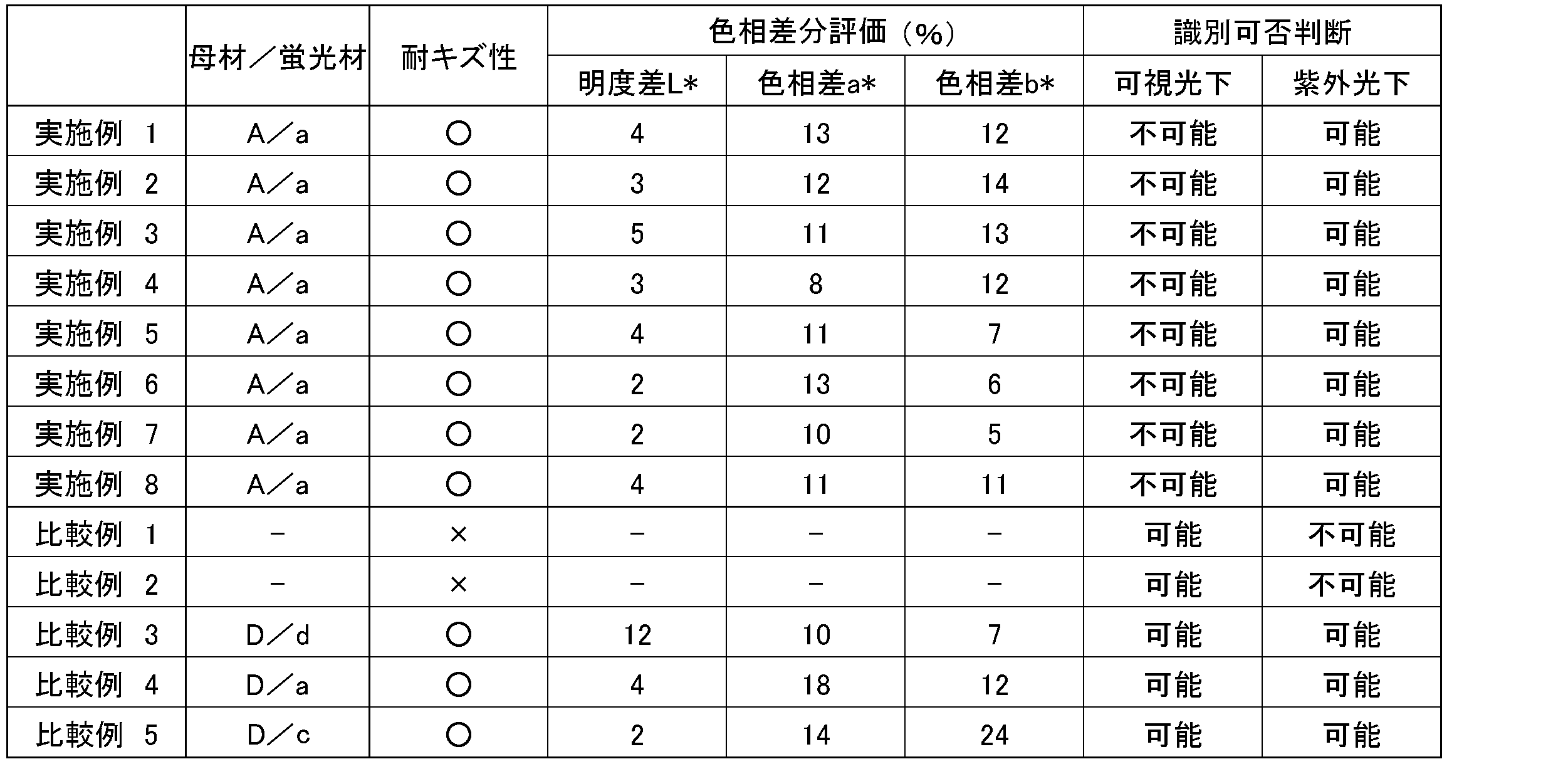
カッターによる耐キズ性評価において、一般的なホログラムがプリントされたカード(比較例1)および顔写真が印刷されたIDカード(比較例2)は容易にキズがついた。一方各実施例の窒化ケイ素セラミックス部材はキズがつかなかった。
色相差分評価による識別可否について、実施例1~8、比較例3~5に示すように、明度L*の差分が5%以内であるとともに、クロマティクネス指数a*およびb*の差分が15%以内である場合において可視光下で識別不可能かつ紫外光下で識別可能であった。
実施例1~8に示す窒化ケイ素セラミックス部材は、いずれも板状体に作製可能であり、かつ所定の形状が可視光下で識別不可能かつ紫外光下で識別可能であった。
色相差分評価による識別可否について、実施例1~8、比較例3~5に示すように、明度L*の差分が5%以内であるとともに、クロマティクネス指数a*およびb*の差分が15%以内である場合において可視光下で識別不可能かつ紫外光下で識別可能であった。
実施例1~8に示す窒化ケイ素セラミックス部材は、いずれも板状体に作製可能であり、かつ所定の形状が可視光下で識別不可能かつ紫外光下で識別可能であった。
窒化ケイ素を主成分とする母材粉末(II)および蛍光材粉末(II)の調製
表3に示す原料粉配合物に成形用バインダーとエタノールを添加し、ボールミルで混合し、スプレードライヤーにて50~80μmに造粒した。
なお、窒化ケイ素(Si3N4)はデンカ社製SN-9FWSを用いた。表3に着色用添加材として示す遷移金属元素およびアルカリ土類金属元素から選ばれた少なくとも1つの元素の化合物は、和光純薬社製:酸化モリブデン(MoO3)を、同じく蛍光用添加材は、高純度化学研究所社製:酸化イッテルビウム(Yb2O3)を、それぞれ用いた。なお、表3に示す原料成分の配合割合は質量%である。
表3に示す原料粉配合物に成形用バインダーとエタノールを添加し、ボールミルで混合し、スプレードライヤーにて50~80μmに造粒した。
なお、窒化ケイ素(Si3N4)はデンカ社製SN-9FWSを用いた。表3に着色用添加材として示す遷移金属元素およびアルカリ土類金属元素から選ばれた少なくとも1つの元素の化合物は、和光純薬社製:酸化モリブデン(MoO3)を、同じく蛍光用添加材は、高純度化学研究所社製:酸化イッテルビウム(Yb2O3)を、それぞれ用いた。なお、表3に示す原料成分の配合割合は質量%である。

窒化ケイ素を主成分とする母材粉末(III)および蛍光材粉末(III)の調製
酸化モリブデンを表4に示す着色用添加材に代える以外は母材粉末F作製と同様にして母材粉末を調製した。この母材粉末は焼結が可能であり、切断・研磨等の後加工に必要な機械的強度を発現した。
また、酸化イッテルビウムを表4に示す蛍光用添加材に代える以外は蛍光材粉末e作製と同様にして蛍光材粉末を調製した。この蛍光材粉末は焼結が可能であり、切断・研磨等の後加工に必要な機械的強度を発現した。
酸化モリブデンを表4に示す着色用添加材に代える以外は母材粉末F作製と同様にして母材粉末を調製した。この母材粉末は焼結が可能であり、切断・研磨等の後加工に必要な機械的強度を発現した。
また、酸化イッテルビウムを表4に示す蛍光用添加材に代える以外は蛍光材粉末e作製と同様にして蛍光材粉末を調製した。この蛍光材粉末は焼結が可能であり、切断・研磨等の後加工に必要な機械的強度を発現した。

実施例9
母材粉末Aの代わりに母材粉末Fを、蛍光材粉末aの代わりに蛍光材粉末eをそれぞれ用いる以外は、実施例1と同一の方法で窒化ケイ素セラミックス部材を製造した。得られた窒化ケイ素セラミックス部材の耐キズ性、色相差分評価および識別可否判断を実施例1と同一の方法で行なった。結果を表5に示す。
母材粉末Aの代わりに母材粉末Fを、蛍光材粉末aの代わりに蛍光材粉末eをそれぞれ用いる以外は、実施例1と同一の方法で窒化ケイ素セラミックス部材を製造した。得られた窒化ケイ素セラミックス部材の耐キズ性、色相差分評価および識別可否判断を実施例1と同一の方法で行なった。結果を表5に示す。
実施例10
母材粉末Aの代わりに母材粉末Fを、蛍光材粉末aの代わりに蛍光材粉末eをそれぞれ用いる以外は、実施例2と同一の方法で窒化ケイ素セラミックス部材を製造した。得られた窒化ケイ素セラミックス部材の評価を実施例1と同一の方法で行なった。結果を表5に示す。
母材粉末Aの代わりに母材粉末Fを、蛍光材粉末aの代わりに蛍光材粉末eをそれぞれ用いる以外は、実施例2と同一の方法で窒化ケイ素セラミックス部材を製造した。得られた窒化ケイ素セラミックス部材の評価を実施例1と同一の方法で行なった。結果を表5に示す。
実施例11
母材粉末Aの代わりに母材粉末Fを、蛍光材粉末aの代わりに蛍光材粉末eをそれぞれ用いる以外は、実施例3と同一の方法で窒化ケイ素セラミックス部材を製造した。得られた窒化ケイ素セラミックス部材の評価を実施例1と同一の方法で行なった。結果を表5に示す。
母材粉末Aの代わりに母材粉末Fを、蛍光材粉末aの代わりに蛍光材粉末eをそれぞれ用いる以外は、実施例3と同一の方法で窒化ケイ素セラミックス部材を製造した。得られた窒化ケイ素セラミックス部材の評価を実施例1と同一の方法で行なった。結果を表5に示す。
実施例12
母材粉末Aの代わりに母材粉末Fを、蛍光材粉末aの代わりに蛍光材粉末eをそれぞれ用いる以外は、実施例4と同一の方法で窒化ケイ素セラミックス部材を製造した。得られた窒化ケイ素セラミックス部材の評価を実施例1と同一の方法で行なった。結果を表5に示す。
母材粉末Aの代わりに母材粉末Fを、蛍光材粉末aの代わりに蛍光材粉末eをそれぞれ用いる以外は、実施例4と同一の方法で窒化ケイ素セラミックス部材を製造した。得られた窒化ケイ素セラミックス部材の評価を実施例1と同一の方法で行なった。結果を表5に示す。
実施例13~16
母材粉末Aの代わりに母材粉末Fを、蛍光材粉末aの代わりに蛍光材粉末eをそれぞれ用いる以外は、実施例5と同一の方法を用いて実施例13、実施例6と同一の方法を用いて実施例14、実施例7と同一の方法を用いて実施例15、および、実施例8と同一の方法を用いて実施例16の窒化ケイ素セラミックス部材をそれぞれ製造した。得られた窒化ケイ素セラミックス部材の評価を実施例1と同一の方法で行なった。結果を表5に示す。
母材粉末Aの代わりに母材粉末Fを、蛍光材粉末aの代わりに蛍光材粉末eをそれぞれ用いる以外は、実施例5と同一の方法を用いて実施例13、実施例6と同一の方法を用いて実施例14、実施例7と同一の方法を用いて実施例15、および、実施例8と同一の方法を用いて実施例16の窒化ケイ素セラミックス部材をそれぞれ製造した。得られた窒化ケイ素セラミックス部材の評価を実施例1と同一の方法で行なった。結果を表5に示す。
比較例6~8
母材粉末および蛍光材粉末を表4に示す組み合わせとして、実施例1と同様にして窒化ケイ素セラミックス部材を製造した。得られた窒化ケイ素セラミックス部材を実施例1と同様にして評価した。結果を表5に示す。なお、表5には比較例1および比較例2の結果を同時に示す。
母材粉末および蛍光材粉末を表4に示す組み合わせとして、実施例1と同様にして窒化ケイ素セラミックス部材を製造した。得られた窒化ケイ素セラミックス部材を実施例1と同様にして評価した。結果を表5に示す。なお、表5には比較例1および比較例2の結果を同時に示す。
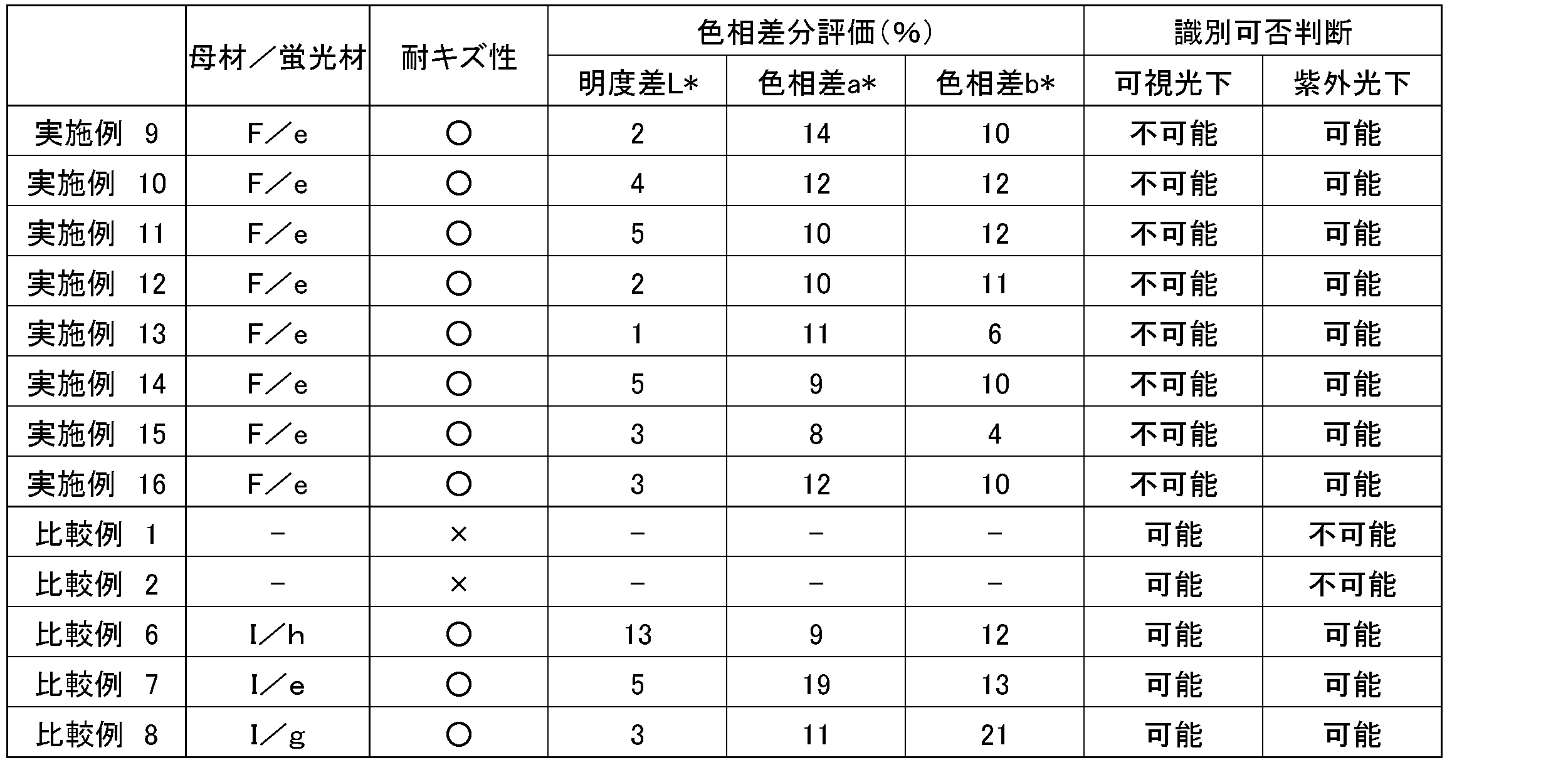
上述したように、カッターによる耐キズ性評価において、一般的なホログラムがプリントされたカード(比較例1)および顔写真が印刷されたIDカード(比較例2)は容易にキズがついた。一方実施例9~16の窒化ケイ素セラミックス部材はキズがつかなかった。
色相差分評価による識別可否について、実施例9~16、比較例6~8に示すように、明度L*の差分が5%以内であるとともに、クロマティクネス指数a*およびb*の差分が15%以内である場合において可視光下で識別不可能かつ紫外光下で識別可能であった。
実施例9~16に示す窒化ケイ素セラミックス部材は、いずれも板状体に作製可能であり、かつ所定の形状が可視光下で識別不可能かつ紫外光下で識別可能であった。
色相差分評価による識別可否について、実施例9~16、比較例6~8に示すように、明度L*の差分が5%以内であるとともに、クロマティクネス指数a*およびb*の差分が15%以内である場合において可視光下で識別不可能かつ紫外光下で識別可能であった。
実施例9~16に示す窒化ケイ素セラミックス部材は、いずれも板状体に作製可能であり、かつ所定の形状が可視光下で識別不可能かつ紫外光下で識別可能であった。
サイアロンを主成分とする母材粉末(IV)および蛍光材粉末(IV)の調製
表6に示す原料粉配合物をボールミルで混合し、スプレードライヤーにて50~80μmの粒子径に造粒した。
なお、サイアロンは、燃焼合成社製燃焼合成サイアロンCSC-β0.5-F05を、窒化ケイ素(Si3N4)はデンカ社製SN-9FWSを用いた。焼結助材としてのイットリア(Y2O3)はH.C.Stark社製GradeCをそれぞれ用いた。また、表6に着色用添加材として示す化合物は、和光純薬社製:酸化モリブデン(MoO3)を、同じく蛍光用添加材は、高純度化学研究所社製:酸化セリウム(CeO2)を、それぞれ用いた。なお、表6に示す原料成分の配合割合は質量%である。
表6に示す原料粉配合物をボールミルで混合し、スプレードライヤーにて50~80μmの粒子径に造粒した。
なお、サイアロンは、燃焼合成社製燃焼合成サイアロンCSC-β0.5-F05を、窒化ケイ素(Si3N4)はデンカ社製SN-9FWSを用いた。焼結助材としてのイットリア(Y2O3)はH.C.Stark社製GradeCをそれぞれ用いた。また、表6に着色用添加材として示す化合物は、和光純薬社製:酸化モリブデン(MoO3)を、同じく蛍光用添加材は、高純度化学研究所社製:酸化セリウム(CeO2)を、それぞれ用いた。なお、表6に示す原料成分の配合割合は質量%である。

実施例17
表6に示す母材粉末Kをプレス板に長板状に敷き詰め、その表面に蛍光材粉末iを所定の形状に配置して全体を板状にプレス成形した。プレス成形の条件は200kgf/cm2である。その後、200kgf/cm2の条件でCIP処理を行ない、成形体を600℃で熱処理してバインダーを除去してから0.8MPa窒素雰囲気中、1700~1800℃で6時間の常圧焼結を行なった。焼結後、蛍光材粉末を配置した面を平面研削盤で研削した後、バフ研磨による鏡面研磨を行なってサイアロンセラミックス部材を製造した。表7に母材粉末と蛍光材粉末の組み合わせを示す。
得られたサイアロンセラミックス部材の耐キズ性、色相差分評価および識別可否判断を実施例1と同一の方法で行なった。結果を表7に示す。
表6に示す母材粉末Kをプレス板に長板状に敷き詰め、その表面に蛍光材粉末iを所定の形状に配置して全体を板状にプレス成形した。プレス成形の条件は200kgf/cm2である。その後、200kgf/cm2の条件でCIP処理を行ない、成形体を600℃で熱処理してバインダーを除去してから0.8MPa窒素雰囲気中、1700~1800℃で6時間の常圧焼結を行なった。焼結後、蛍光材粉末を配置した面を平面研削盤で研削した後、バフ研磨による鏡面研磨を行なってサイアロンセラミックス部材を製造した。表7に母材粉末と蛍光材粉末の組み合わせを示す。
得られたサイアロンセラミックス部材の耐キズ性、色相差分評価および識別可否判断を実施例1と同一の方法で行なった。結果を表7に示す。
実施例18
表6に示す母材粉末Kを用いて、凹部を表面に有する長板状に金型を用いて成形した。また、表6に示す蛍光材粉末iを表面に形成された凹部に嵌合できる形状に成形した。その後、両成形体を相互に嵌合することで成形体を得た。この成形体を実施例17と同様にして、CIP処理、焼結処理、研磨処理を施してサイアロンセラミックス部材を製造した。得られたサイアロンセラミックス部材を実施例1と同様にして評価した。結果を表7に示す。
表6に示す母材粉末Kを用いて、凹部を表面に有する長板状に金型を用いて成形した。また、表6に示す蛍光材粉末iを表面に形成された凹部に嵌合できる形状に成形した。その後、両成形体を相互に嵌合することで成形体を得た。この成形体を実施例17と同様にして、CIP処理、焼結処理、研磨処理を施してサイアロンセラミックス部材を製造した。得られたサイアロンセラミックス部材を実施例1と同様にして評価した。結果を表7に示す。
実施例19
表6に示す母材粉末Kをプレス板に長板状に敷き詰め全体を板状にプレス成形した。この板状成形体の表面を工具で削ることで凹部を表面に有する長板状に成形した。その後、表1に示す蛍光材粉末iを上記凹部に投入してプレス成形により成形した。この成形体を実施例17と同様に処理してサイアロンセラミックス部材を製造した。得られたサイアロンセラミックス部材を実施例1と同様にして評価した。結果を表7に示す。
表6に示す母材粉末Kをプレス板に長板状に敷き詰め全体を板状にプレス成形した。この板状成形体の表面を工具で削ることで凹部を表面に有する長板状に成形した。その後、表1に示す蛍光材粉末iを上記凹部に投入してプレス成形により成形した。この成形体を実施例17と同様に処理してサイアロンセラミックス部材を製造した。得られたサイアロンセラミックス部材を実施例1と同様にして評価した。結果を表7に示す。
実施例20
表6に示す母材粉末Kを金型内に投入して仮押しして板状とする。また、表6に示す蛍光材粉末iをエタノール中に分散させてスラリー状に調製した。このスラリー液を用いて、インクジェット法により上記板状体の表面に棒状もしくは四角形状を成し、特定の幾何学配置を有する形状を描画し、エタノールが揮発した後にプレス成形した。この成形体を実施例17と同様に処理してサイアロンセラミックス部材を製造した。得られたサイアロンセラミックス部材を実施例1と同様にして評価した。結果を表7に示す。
表6に示す母材粉末Kを金型内に投入して仮押しして板状とする。また、表6に示す蛍光材粉末iをエタノール中に分散させてスラリー状に調製した。このスラリー液を用いて、インクジェット法により上記板状体の表面に棒状もしくは四角形状を成し、特定の幾何学配置を有する形状を描画し、エタノールが揮発した後にプレス成形した。この成形体を実施例17と同様に処理してサイアロンセラミックス部材を製造した。得られたサイアロンセラミックス部材を実施例1と同様にして評価した。結果を表7に示す。
実施例21~24
実施例20において、特定の幾何学配置を有する形状の代わりに、ランダムな形状を再現した配置として、マトリックス型二次元コード(登録商標;QRコード)状(実施例21)、バーコード状(実施例22)、事前にスキャニングした筆跡を再現する形状(実施例23)、事前にスキャニングした指紋を再現する形状(実施例24)に描画し、エタノールが揮発した後にプレス成形した。この成形体を実施例17と同様に処理してサイアロンセラミックス部材を製造した。得られたサイアロンセラミックス部材を実施例1と同様にして評価した。結果を表7に示す。
実施例20において、特定の幾何学配置を有する形状の代わりに、ランダムな形状を再現した配置として、マトリックス型二次元コード(登録商標;QRコード)状(実施例21)、バーコード状(実施例22)、事前にスキャニングした筆跡を再現する形状(実施例23)、事前にスキャニングした指紋を再現する形状(実施例24)に描画し、エタノールが揮発した後にプレス成形した。この成形体を実施例17と同様に処理してサイアロンセラミックス部材を製造した。得られたサイアロンセラミックス部材を実施例1と同様にして評価した。結果を表7に示す。
比較例1および2
カード表面の硬度を評価するため、市販されている一般的なホログラムがプリントされたカード(比較例1)および顔写真が印刷されたIDカード(比較例2)を準備して、実施例1と同様に耐キズ性を評価した。結果を表2に示す。
カード表面の硬度を評価するため、市販されている一般的なホログラムがプリントされたカード(比較例1)および顔写真が印刷されたIDカード(比較例2)を準備して、実施例1と同様に耐キズ性を評価した。結果を表2に示す。
比較例9~11
母材粉末および蛍光材粉末を表7に示す組み合わせとして、実施例17と同様にしてサイアロンセラミックス部材を製造した。得られたサイアロンセラミックス部材を実施例1と同様にして評価した。結果を表7に示す。なお、表7には比較例1および比較例2の結果を同時に示す。
母材粉末および蛍光材粉末を表7に示す組み合わせとして、実施例17と同様にしてサイアロンセラミックス部材を製造した。得られたサイアロンセラミックス部材を実施例1と同様にして評価した。結果を表7に示す。なお、表7には比較例1および比較例2の結果を同時に示す。
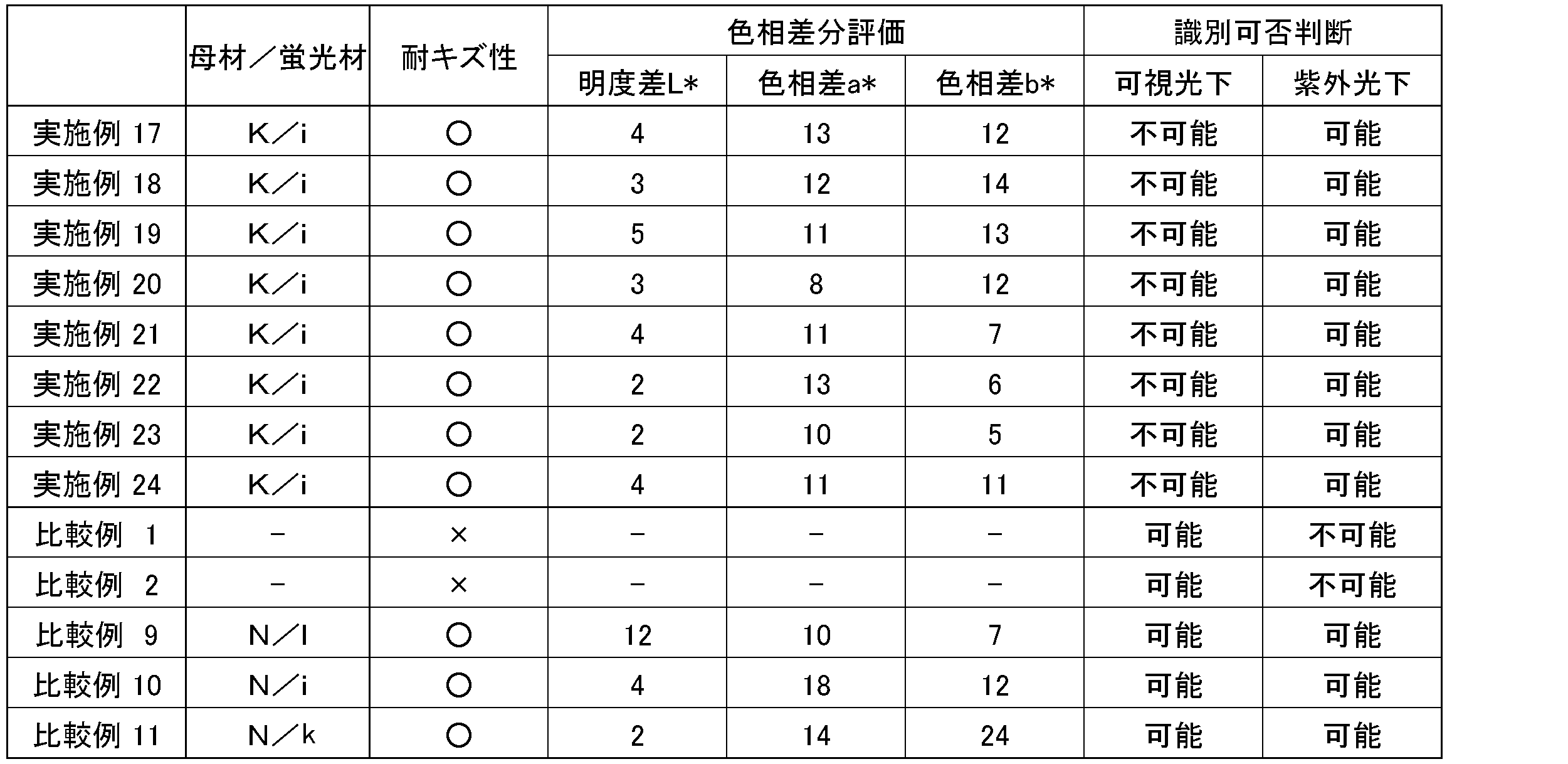
カッターによる耐キズ性評価において、一般的なホログラムがプリントされたカード(比較例1)および顔写真が印刷されたIDカード(比較例2)は容易にキズがついた。一方各実施例のサイアロンセラミックス部材はキズがつかなかった。
色相差分評価による識別可否について、実施例17~24、比較例9~11に示すように、明度L*の差分が5%以内であるとともに、クロマティクネス指数a*およびb*の差分が15%以内である場合において可視光下で識別不可能かつ紫外光下で識別可能であった。
実施例17~24に示すサイアロンセラミックス部材は、いずれも板状体に作製可能であり、かつ所定の形状が可視光下で識別不可能かつ紫外光下で識別可能であった。
色相差分評価による識別可否について、実施例17~24、比較例9~11に示すように、明度L*の差分が5%以内であるとともに、クロマティクネス指数a*およびb*の差分が15%以内である場合において可視光下で識別不可能かつ紫外光下で識別可能であった。
実施例17~24に示すサイアロンセラミックス部材は、いずれも板状体に作製可能であり、かつ所定の形状が可視光下で識別不可能かつ紫外光下で識別可能であった。
サイアロンを主成分とする母材粉末(V)および蛍光材粉末(V)の調製
表8に示す原料粉配合物に成形用バインダーとエタノールを添加し、ボールミルで混合し、スプレードライヤーにて50~80μmに造粒した。
なお、サイアロンは、燃焼合成社製燃焼合成サイアロンCSC-β0.5-F05を、窒化ケイ素(Si3N4)はデンカ社製SN-9FWSを用いた。また、表8に着色用添加材として示す化合物は、和光純薬社製:酸化モリブデン(MoO3)を、同じく蛍光用添加材は、高純度化学研究所社製:酸化イッテルビウム(Yb2O3)を、それぞれ用いた。なお、表8に示す原料成分の配合割合は質量%である。
表8に示す原料粉配合物に成形用バインダーとエタノールを添加し、ボールミルで混合し、スプレードライヤーにて50~80μmに造粒した。
なお、サイアロンは、燃焼合成社製燃焼合成サイアロンCSC-β0.5-F05を、窒化ケイ素(Si3N4)はデンカ社製SN-9FWSを用いた。また、表8に着色用添加材として示す化合物は、和光純薬社製:酸化モリブデン(MoO3)を、同じく蛍光用添加材は、高純度化学研究所社製:酸化イッテルビウム(Yb2O3)を、それぞれ用いた。なお、表8に示す原料成分の配合割合は質量%である。

サイアロンを主成分とする母材粉末(VI)および蛍光材粉末(VI)の調製
酸化モリブデンを上記表4に示す着色用添加材に代える以外は母材粉末P作製と同様にして母材粉末を調製した。この母材粉末は焼結が可能であり、切断・研磨等の後加工に必要な機械的強度を発現した。
また、酸化イッテルビウムを上記表4に示す蛍光用添加材に代える以外は蛍光材粉末m作製と同様にして蛍光材粉末を調製した。この蛍光材粉末は焼結が可能であり、切断・研磨等の後加工に必要な機械的強度を発現した。
酸化モリブデンを上記表4に示す着色用添加材に代える以外は母材粉末P作製と同様にして母材粉末を調製した。この母材粉末は焼結が可能であり、切断・研磨等の後加工に必要な機械的強度を発現した。
また、酸化イッテルビウムを上記表4に示す蛍光用添加材に代える以外は蛍光材粉末m作製と同様にして蛍光材粉末を調製した。この蛍光材粉末は焼結が可能であり、切断・研磨等の後加工に必要な機械的強度を発現した。
実施例25~28
母材粉末Kの代わりに母材粉末Pを、蛍光材粉末iの代わりに蛍光材粉末mをそれぞれ用いる以外は、実施例17と同一の方法でサイアロンセラミックス部材を製造した。得られたサイアロンセラミックス部材の耐キズ性、色相差分評価および識別可否判断を実施例1と同一の方法で行なった。結果を表9に示す。
母材粉末Kの代わりに母材粉末Pを、蛍光材粉末iの代わりに蛍光材粉末mをそれぞれ用いる以外は、実施例17と同一の方法でサイアロンセラミックス部材を製造した。得られたサイアロンセラミックス部材の耐キズ性、色相差分評価および識別可否判断を実施例1と同一の方法で行なった。結果を表9に示す。
実施例29~32
母材粉末Kの代わりに母材粉末Pを、蛍光材粉末iの代わりに蛍光材粉末mをそれぞれ用いる以外は、実施例17と同一の方法を用いて実施例29、実施例18と同一の方法を用いて実施例30、実施例19と同一の方法を用いて実施例31、および、実施例20と同一の方法を用いて実施例32のサイアロンセラミックス部材をそれぞれ製造した。得られたサイアロンセラミックス部材の評価を実施例17と同一の方法で行なった。結果を表9に示す。
母材粉末Kの代わりに母材粉末Pを、蛍光材粉末iの代わりに蛍光材粉末mをそれぞれ用いる以外は、実施例17と同一の方法を用いて実施例29、実施例18と同一の方法を用いて実施例30、実施例19と同一の方法を用いて実施例31、および、実施例20と同一の方法を用いて実施例32のサイアロンセラミックス部材をそれぞれ製造した。得られたサイアロンセラミックス部材の評価を実施例17と同一の方法で行なった。結果を表9に示す。
比較例12~14
母材粉末および蛍光材粉末を表9に示す組み合わせとして、実施例17と同様にしてサイアロンセラミックス部材を製造した。得られたサイアロンセラミックス部材を実施例17と同様にして評価した。結果を表9に示す。なお、表9には比較例1および比較例2の結果を同時に示す。
母材粉末および蛍光材粉末を表9に示す組み合わせとして、実施例17と同様にしてサイアロンセラミックス部材を製造した。得られたサイアロンセラミックス部材を実施例17と同様にして評価した。結果を表9に示す。なお、表9には比較例1および比較例2の結果を同時に示す。

上述したように、カッターによる耐キズ性評価において、一般的なホログラムがプリントされたカード(比較例1)および顔写真が印刷されたIDカード(比較例2)は容易にキズがついた。一方実施例25~32のサイアロンセラミックス部材はキズがつかなかった。
色相差分評価による識別可否について、実施例25~32、比較例12~14に示すように、明度L*の差分が5%以内であるとともに、クロマティクネス指数a*およびb*の差分が15%以内である場合において可視光下で識別不可能かつ紫外光下で識別可能であった。
実施例25~32に示すサイアロンセラミックス部材は、いずれも板状体に作製可能であり、かつ所定の形状が可視光下で識別不可能かつ紫外光下で識別可能であった。
色相差分評価による識別可否について、実施例25~32、比較例12~14に示すように、明度L*の差分が5%以内であるとともに、クロマティクネス指数a*およびb*の差分が15%以内である場合において可視光下で識別不可能かつ紫外光下で識別可能であった。
実施例25~32に示すサイアロンセラミックス部材は、いずれも板状体に作製可能であり、かつ所定の形状が可視光下で識別不可能かつ紫外光下で識別可能であった。
本発明の窒化ケイ素系セラミックス部材は、表面が平滑なセラミックス部材であり、可視光下で識別不可能かつ紫外光下で識別可能な形状を表面に有しているので、偽造防止を目的とした各種カード類に応用できる。
1 窒化ケイ素系セラミックス部材
2 母材焼結体
3 蛍光材焼結体
2 母材焼結体
3 蛍光材焼結体
Claims (12)
- 母材焼結体の表面に蛍光材焼結体が配置されて、研磨表面を有する成形体からなる窒化ケイ素系セラミックス部材であって、
前記母材焼結体は、遷移金属元素およびアルカリ土類金属元素から選ばれた少なくとも1つの元素の化合物を含む窒化ケイ素系セラミックスであり、
前記蛍光材焼結体は、遷移金属元素およびアルカリ土類金属元素から選ばれた少なくとも1つの元素の化合物、およびランタノイド元素の化合物を含む窒化ケイ素系セラミックスであり、
前記化合物が酸化物、窒化物、酸窒化物、または炭化物であり、
紫外光照射下において、前記母材焼結体の表面相と前記蛍光材焼結体の表面相とが形状識別可能に前記研磨表面に表れることを特徴とする窒化ケイ素系セラミックス部材。 - 前記窒化ケイ素系セラミックスが少なくとも65質量%超の窒化ケイ素を含むことを特徴とする請求項1記載の窒化ケイ素系セラミックス部材。
- 前記窒化ケイ素系セラミックスが少なくとも60質量%超のサイアロンを含むことを特徴とする請求項1記載の窒化ケイ素系セラミックス部材。
- 前記母材焼結体および前記蛍光材焼結体を構成する窒化ケイ素系セラミックスは、焼結助剤を含有する窒化ケイ素系セラミックスであることを特徴とする請求項1記載の窒化ケイ素系セラミックス部材。
- 前記母材焼結体および前記蛍光材焼結体を構成する窒化ケイ素系セラミックスは、前記遷移金属元素およびアルカリ土類金属元素から選ばれた少なくとも1つの元素の化合物を焼結助剤とすることを特徴とする請求項1記載の窒化ケイ素系セラミックス部材。
- 前記遷移金属元素は、ランタノイド元素を含まない遷移金属元素であることを特徴とする請求項1記載の窒化ケイ素系セラミックス部材。
- 前記遷移金属元素およびアルカリ土類金属元素から選ばれた少なくとも1つの元素の化合物の配合割合は、窒化ケイ素系セラミックス全体に対して、5~20質量%であることを特徴とする請求項1記載の窒化ケイ素系セラミックス部材。
- 前記ランタノイド元素の化合物の配合割合は、窒化ケイ素系セラミックス全体に対して、1~10質量%であることを特徴とする請求項7記載の窒化ケイ素系セラミックス部材。
- 前記母材焼結体の表面相および前記蛍光材焼結体の表面相についてCIE 1976 L*a*b*色空間における明度指数L*の差分が5%以内であり、かつクロマティクネス指数a*およびb*の差分が15%以内であることを特徴とする請求項1記載の窒化ケイ素系セラミックス部材。
- 前記母材焼結体の表面相および前記蛍光材焼結体の表面相は、可視光照射下において、形状識別が認識できないことを特徴とする請求項1記載の窒化ケイ素系セラミックス部材。
- 前記母材焼結体の表面相と前記蛍光材焼結体の表面相とは紫外光下において相互に明確な輪郭を有して配置されていることを特徴とする請求項1記載の窒化ケイ素系セラミックス部材。
- 前記明確な輪郭は、前記母材焼結体の表面相内に前記蛍光材焼結体の表面相が幾何学的模様またはランダムな形状模様に配置されていることを特徴とする請求項11記載の窒化ケイ素系セラミックス部材。
Applications Claiming Priority (8)
| Application Number | Priority Date | Filing Date | Title |
|---|---|---|---|
| JP2015-184378 | 2015-09-17 | ||
| JP2015-184404 | 2015-09-17 | ||
| JP2015184378 | 2015-09-17 | ||
| JP2015184404 | 2015-09-17 | ||
| JP2016-176112 | 2016-09-09 | ||
| JP2016-176104 | 2016-09-09 | ||
| JP2016176112A JP2017057137A (ja) | 2015-09-17 | 2016-09-09 | サイアロンセラミックス部材 |
| JP2016176104A JP2017057136A (ja) | 2015-09-17 | 2016-09-09 | 窒化ケイ素セラミックス部材 |
Publications (1)
| Publication Number | Publication Date |
|---|---|
| WO2017047780A1 true WO2017047780A1 (ja) | 2017-03-23 |
Family
ID=58289405
Family Applications (1)
| Application Number | Title | Priority Date | Filing Date |
|---|---|---|---|
| PCT/JP2016/077530 Ceased WO2017047780A1 (ja) | 2015-09-17 | 2016-09-16 | 窒化ケイ素系セラミックス部材 |
Country Status (1)
| Country | Link |
|---|---|
| WO (1) | WO2017047780A1 (ja) |
Cited By (2)
| Publication number | Priority date | Publication date | Assignee | Title |
|---|---|---|---|---|
| WO2025084413A1 (ja) * | 2023-10-20 | 2025-04-24 | 日本製鉄株式会社 | 窒化珪素質焼結体及びその製造方法 |
| WO2025084410A1 (ja) * | 2023-10-20 | 2025-04-24 | 日本製鉄株式会社 | 窒化珪素質焼結体及びその製造方法 |
Citations (3)
| Publication number | Priority date | Publication date | Assignee | Title |
|---|---|---|---|---|
| JP2006152069A (ja) * | 2004-11-26 | 2006-06-15 | Fujikura Ltd | アルファサイアロン蛍光体とその製造方法、アルファサイアロン蛍光体中間生成物、アルファサイアロン蛍光体原料粉末及び発光ダイオードランプ |
| JP2007262417A (ja) * | 2007-05-18 | 2007-10-11 | National Institute For Materials Science | 蛍光体 |
| JP2009160837A (ja) * | 2008-01-08 | 2009-07-23 | Toppan Printing Co Ltd | 偽造防止媒体及び偽造防止媒体の判別方法 |
-
2016
- 2016-09-16 WO PCT/JP2016/077530 patent/WO2017047780A1/ja not_active Ceased
Patent Citations (3)
| Publication number | Priority date | Publication date | Assignee | Title |
|---|---|---|---|---|
| JP2006152069A (ja) * | 2004-11-26 | 2006-06-15 | Fujikura Ltd | アルファサイアロン蛍光体とその製造方法、アルファサイアロン蛍光体中間生成物、アルファサイアロン蛍光体原料粉末及び発光ダイオードランプ |
| JP2007262417A (ja) * | 2007-05-18 | 2007-10-11 | National Institute For Materials Science | 蛍光体 |
| JP2009160837A (ja) * | 2008-01-08 | 2009-07-23 | Toppan Printing Co Ltd | 偽造防止媒体及び偽造防止媒体の判別方法 |
Cited By (2)
| Publication number | Priority date | Publication date | Assignee | Title |
|---|---|---|---|---|
| WO2025084413A1 (ja) * | 2023-10-20 | 2025-04-24 | 日本製鉄株式会社 | 窒化珪素質焼結体及びその製造方法 |
| WO2025084410A1 (ja) * | 2023-10-20 | 2025-04-24 | 日本製鉄株式会社 | 窒化珪素質焼結体及びその製造方法 |
Similar Documents
| Publication | Publication Date | Title |
|---|---|---|
| CN107922272B (zh) | 红色氧化锆烧结体及其制造方法 | |
| Krell et al. | Defect strategies for an improved optical quality of transparent ceramics | |
| CN107108374B (zh) | 透光性氧化锆烧结体和其制造方法以及其用途 | |
| YT et al. | Effect of grain size on transmittance and mechanical strength of sintered alumina | |
| CN112714686B (zh) | 具有织构的陶瓷壳体 | |
| CN112585103B (zh) | 氧化锆烧结体及其制造方法 | |
| KR102141347B1 (ko) | 세라믹스 소결체 | |
| CN106660885A (zh) | 着色透光性氧化锆烧结体和粉末及其用途 | |
| CN112624761A (zh) | 氧化锆烧结体及其制造方法 | |
| CN103080045A (zh) | 氧化锆烧结体及其烧结用组合物和假烧体 | |
| JP6331840B2 (ja) | 赤色ジルコニア焼結体及びその製造方法 | |
| JP7516780B2 (ja) | ジルコニア焼結体 | |
| KR20210037612A (ko) | 흑색 소결체 및 이의 제조 방법 | |
| JP6657765B2 (ja) | 黒色ジルコニア焼結体及びその用途 | |
| EP4458788A1 (en) | Sintered body, method for producing sintered body, starting material powder for sintered body, and calcined body | |
| WO2017047780A1 (ja) | 窒化ケイ素系セラミックス部材 | |
| KR20240146685A (ko) | 지르코니아 적층체 | |
| KR20240140940A (ko) | 분말 및 그 제조 방법 | |
| Suárez et al. | Synthesis and processing of spinel powders for transparent ceramics | |
| JP6885021B2 (ja) | オレンジ色ジルコニア焼結体及びその製造方法 | |
| JP2017057136A (ja) | 窒化ケイ素セラミックス部材 | |
| JP2017057137A (ja) | サイアロンセラミックス部材 | |
| CN119301091A (zh) | 黑色氧化锆复合烧结体及其制造方法 | |
| JP3000685B2 (ja) | 透光性イットリア焼結体及びその製造方法 | |
| Gan et al. | Mechanical properties of submicrometer‐grained transparent yttria ceramics by hot pressing with hot‐isostatic pressing |
Legal Events
| Date | Code | Title | Description |
|---|---|---|---|
| 121 | Ep: the epo has been informed by wipo that ep was designated in this application |
Ref document number: 16846651 Country of ref document: EP Kind code of ref document: A1 |
|
| NENP | Non-entry into the national phase |
Ref country code: DE |
|
| 122 | Ep: pct application non-entry in european phase |
Ref document number: 16846651 Country of ref document: EP Kind code of ref document: A1 |